JP5527019B2 - Physical quantity sensor and electronic equipment - Google Patents
Physical quantity sensor and electronic equipment Download PDFInfo
- Publication number
- JP5527019B2 JP5527019B2 JP2010122959A JP2010122959A JP5527019B2 JP 5527019 B2 JP5527019 B2 JP 5527019B2 JP 2010122959 A JP2010122959 A JP 2010122959A JP 2010122959 A JP2010122959 A JP 2010122959A JP 5527019 B2 JP5527019 B2 JP 5527019B2
- Authority
- JP
- Japan
- Prior art keywords
- region
- physical quantity
- quantity sensor
- oscillator
- acceleration
- Prior art date
- Legal status (The legal status is an assumption and is not a legal conclusion. Google has not performed a legal analysis and makes no representation as to the accuracy of the status listed.)
- Expired - Fee Related
Links
Images


Classifications
-
- G—PHYSICS
- G01—MEASURING; TESTING
- G01P—MEASURING LINEAR OR ANGULAR SPEED, ACCELERATION, DECELERATION, OR SHOCK; INDICATING PRESENCE, ABSENCE, OR DIRECTION, OF MOVEMENT
- G01P15/00—Measuring acceleration; Measuring deceleration; Measuring shock, i.e. sudden change of acceleration
- G01P15/02—Measuring acceleration; Measuring deceleration; Measuring shock, i.e. sudden change of acceleration by making use of inertia forces using solid seismic masses
- G01P15/08—Measuring acceleration; Measuring deceleration; Measuring shock, i.e. sudden change of acceleration by making use of inertia forces using solid seismic masses with conversion into electric or magnetic values
- G01P15/0802—Details
-
- G—PHYSICS
- G01—MEASURING; TESTING
- G01P—MEASURING LINEAR OR ANGULAR SPEED, ACCELERATION, DECELERATION, OR SHOCK; INDICATING PRESENCE, ABSENCE, OR DIRECTION, OF MOVEMENT
- G01P15/00—Measuring acceleration; Measuring deceleration; Measuring shock, i.e. sudden change of acceleration
- G01P15/02—Measuring acceleration; Measuring deceleration; Measuring shock, i.e. sudden change of acceleration by making use of inertia forces using solid seismic masses
-
- G—PHYSICS
- G01—MEASURING; TESTING
- G01P—MEASURING LINEAR OR ANGULAR SPEED, ACCELERATION, DECELERATION, OR SHOCK; INDICATING PRESENCE, ABSENCE, OR DIRECTION, OF MOVEMENT
- G01P15/00—Measuring acceleration; Measuring deceleration; Measuring shock, i.e. sudden change of acceleration
-
- B—PERFORMING OPERATIONS; TRANSPORTING
- B81—MICROSTRUCTURAL TECHNOLOGY
- B81B—MICROSTRUCTURAL DEVICES OR SYSTEMS, e.g. MICROMECHANICAL DEVICES
- B81B7/00—Microstructural systems; Auxiliary parts of microstructural devices or systems
- B81B7/02—Microstructural systems; Auxiliary parts of microstructural devices or systems containing distinct electrical or optical devices of particular relevance for their function, e.g. microelectro-mechanical systems [MEMS]
-
- G—PHYSICS
- G01—MEASURING; TESTING
- G01C—MEASURING DISTANCES, LEVELS OR BEARINGS; SURVEYING; NAVIGATION; GYROSCOPIC INSTRUMENTS; PHOTOGRAMMETRY OR VIDEOGRAMMETRY
- G01C19/00—Gyroscopes; Turn-sensitive devices using vibrating masses; Turn-sensitive devices without moving masses; Measuring angular rate using gyroscopic effects
- G01C19/56—Turn-sensitive devices using vibrating masses, e.g. vibratory angular rate sensors based on Coriolis forces
-
- G—PHYSICS
- G01—MEASURING; TESTING
- G01P—MEASURING LINEAR OR ANGULAR SPEED, ACCELERATION, DECELERATION, OR SHOCK; INDICATING PRESENCE, ABSENCE, OR DIRECTION, OF MOVEMENT
- G01P15/00—Measuring acceleration; Measuring deceleration; Measuring shock, i.e. sudden change of acceleration
- G01P15/02—Measuring acceleration; Measuring deceleration; Measuring shock, i.e. sudden change of acceleration by making use of inertia forces using solid seismic masses
- G01P15/08—Measuring acceleration; Measuring deceleration; Measuring shock, i.e. sudden change of acceleration by making use of inertia forces using solid seismic masses with conversion into electric or magnetic values
- G01P15/125—Measuring acceleration; Measuring deceleration; Measuring shock, i.e. sudden change of acceleration by making use of inertia forces using solid seismic masses with conversion into electric or magnetic values by capacitive pick-up
-
- G—PHYSICS
- G01—MEASURING; TESTING
- G01P—MEASURING LINEAR OR ANGULAR SPEED, ACCELERATION, DECELERATION, OR SHOCK; INDICATING PRESENCE, ABSENCE, OR DIRECTION, OF MOVEMENT
- G01P15/00—Measuring acceleration; Measuring deceleration; Measuring shock, i.e. sudden change of acceleration
- G01P15/18—Measuring acceleration; Measuring deceleration; Measuring shock, i.e. sudden change of acceleration in two or more dimensions
-
- G—PHYSICS
- G01—MEASURING; TESTING
- G01P—MEASURING LINEAR OR ANGULAR SPEED, ACCELERATION, DECELERATION, OR SHOCK; INDICATING PRESENCE, ABSENCE, OR DIRECTION, OF MOVEMENT
- G01P15/00—Measuring acceleration; Measuring deceleration; Measuring shock, i.e. sudden change of acceleration
- G01P15/02—Measuring acceleration; Measuring deceleration; Measuring shock, i.e. sudden change of acceleration by making use of inertia forces using solid seismic masses
- G01P15/08—Measuring acceleration; Measuring deceleration; Measuring shock, i.e. sudden change of acceleration by making use of inertia forces using solid seismic masses with conversion into electric or magnetic values
- G01P2015/0805—Measuring acceleration; Measuring deceleration; Measuring shock, i.e. sudden change of acceleration by making use of inertia forces using solid seismic masses with conversion into electric or magnetic values being provided with a particular type of spring-mass-system for defining the displacement of a seismic mass due to an external acceleration
- G01P2015/0822—Measuring acceleration; Measuring deceleration; Measuring shock, i.e. sudden change of acceleration by making use of inertia forces using solid seismic masses with conversion into electric or magnetic values being provided with a particular type of spring-mass-system for defining the displacement of a seismic mass due to an external acceleration for defining out-of-plane movement of the mass
- G01P2015/0825—Measuring acceleration; Measuring deceleration; Measuring shock, i.e. sudden change of acceleration by making use of inertia forces using solid seismic masses with conversion into electric or magnetic values being provided with a particular type of spring-mass-system for defining the displacement of a seismic mass due to an external acceleration for defining out-of-plane movement of the mass for one single degree of freedom of movement of the mass
- G01P2015/0831—Measuring acceleration; Measuring deceleration; Measuring shock, i.e. sudden change of acceleration by making use of inertia forces using solid seismic masses with conversion into electric or magnetic values being provided with a particular type of spring-mass-system for defining the displacement of a seismic mass due to an external acceleration for defining out-of-plane movement of the mass for one single degree of freedom of movement of the mass the mass being of the paddle type having the pivot axis between the longitudinal ends of the mass, e.g. see-saw configuration
Description
本発明は、例えば、MEMSセンサー(Micro Electro Mechanical System Sensor:マイクロエレクトロメカニカルシステムセンサー)等の物理量センサーおよび電子機器等に関する。 The present invention relates to a physical quantity sensor such as a MEMS sensor (Micro Electro Mechanical System Sensor) and an electronic device.
近年、MEMS(Micro Electro Mechanical System:微小電気機械システム)技術を使用して、小型で高感度の物理量センサーを実現する技術が注目されている。 In recent years, attention has been focused on a technology for realizing a small and highly sensitive physical quantity sensor using MEMS (Micro Electro Mechanical System) technology.
例えば、特許文献1には、振り子式容量性加速度計が開示されている。特許文献1の振り子式容量性加速度計は、基板と、検知プレートと、基板上で検知プレートを支持する中心アンカー部と、検知プレートに設けられた電極と、基板上に設けられる電極とを有する。検知プレートは、中心アンカー部に対して左側に設けられる、中空部を持たないプルーフマス(慣性質量と、中空部を有するプルーフマスと、を有する。加速度によって各プルーフマスに回転モーメントが加わると、検知プレートは、中心アンカー部(ヒンジ軸)を中心としてシーソー動作を行う。検知プレートのシーソー動作に対応して静電容量の容量値が変化し、差動容量性出力信号が、振り子式容量性加速度計から出力される。
For example,
また、特許文献2には、シリコン基板上に、非対称に配置された回転軸線によって支持された揺動体を形成し、Z方向の加速度を受けたときに揺動体の傾きが一方に偏ること(シーソー揺動)を利用して、容量を差動検出し、Z軸方向の加速度を検出する加速度センサが開示されている。
In
特許文献1に開示される振り子式容量性加速度計では、加速度計を保護するパッケージの形成については何ら考慮されていない。
In the pendulum capacitive accelerometer disclosed in
また、特許文献2の加速度センサーでは、Z方向以外のX方向やY方向に加速度が発生した場合においても、揺動体に揺動が発生してしまい、見かけ上、Z方向の加速度が変化したことになる。このような検出方向とは異なる方向に検出感度をもつことは、物理量センサーの検出精度の低下の原因となり問題となっていた。
Further, in the acceleration sensor of
本発明の少なくとも一つの態様によれば、例えば、パッケージを含めた物理量センサーの組み立て性を向上することができる。また、本発明の少なくとも一つの態様によれば、例えば、検出軸以外の方向に生じる加速度によって物理量センサーの検出感度が低下することを抑制することができる。 According to at least one aspect of the present invention, for example, the assembly of a physical quantity sensor including a package can be improved. Moreover, according to at least one aspect of the present invention, for example, it is possible to suppress a decrease in detection sensitivity of the physical quantity sensor due to acceleration generated in a direction other than the detection axis.
(1)本発明の物理量センサーの一態様は、ベースと、前記ベース上に空隙を介して配置された基板と、を有し、前記基板は開口部を有し、前記開口部に第1揺動体と第2揺動体とが配置され、前記第1揺動体は、第1支持部と第2支持部と第1可動電極とを含み、第1軸上に配置された前記第1支持部と前記第2支持部とによって前記基板に支持され、且つ、平面視で前記第1軸によって第1の領域と第2の領域とに区画され、各々の領域に前記第1可動電極が形成され、前記第2揺動体は、第3支持部と第4支持部と第2可動電極とを含み、第2軸上に配置された前記第3支持部と前記第4支持部とによって前記基板に支持され、且つ、平面視で前記第2軸によって第3の領域と第4の領域とに区画され、各々の領域に前記第2可動電極が形成され、前記ベースには、前記第1可動電極と前記第2可動電極とに対向して固定電極が形成され、前記第2の領域の質量は前記第1の領域の質量よりも重く、前記第4の領域の質量は前記第3の領域よりも重く、前記第1の領域と前記第2の領域の並び方向と前記第3の領域と前記第4の領域の並び方向とは互いに同じであり、且つ、重力を受けた状態において前記第1揺動体および前記第2揺動体は互いに反対向きに傾斜している。 (1) One aspect of the physical quantity sensor of the present invention includes a base and a substrate disposed on the base via a gap, the substrate having an opening, and the first swing is formed in the opening. A moving body and a second oscillating body are disposed, and the first oscillating body includes a first support portion, a second support portion, and a first movable electrode, and the first support portion is disposed on a first axis. Supported by the substrate by the second support portion, and partitioned into a first region and a second region by the first axis in plan view, and the first movable electrode is formed in each region; The second oscillator includes a third support portion, a fourth support portion, and a second movable electrode, and is supported on the substrate by the third support portion and the fourth support portion disposed on a second axis. And is divided into a third region and a fourth region by the second axis in plan view, and the second movable electrode is provided in each region. The fixed electrode is formed on the base so as to face the first movable electrode and the second movable electrode, and the mass of the second region is heavier than the mass of the first region, The mass of the fourth region is heavier than that of the third region, and the alignment direction of the first region and the second region is the same as the alignment direction of the third region and the fourth region. In addition, the first oscillating body and the second oscillating body are inclined in directions opposite to each other in a state of being subjected to gravity.
本態様は、シーソー構造を利用した物理量センサーの検出精度をより向上させるための構成に関係する。例えば重力加速度が作用している状態では、揺動体は、質量の不均衡により回転モーメントが不均衡になり、傾いた状態となっている(重力加速度が加わっているにも関わらず、揺動体が水平状態を保っていたのでは、重力加速度を検出できないからである)。この状態で、揺動体に、揺動体の延在方向(揺動体が水平な状態であるときの延在方向)である第1方向の加速度が作用した場合を想定する。傾いている揺動体に対して第1方向の加速度が作用すると、揺動体には、第1方向の加速度の向きとは逆向きに慣性力が働く(慣性力の大きさは、第1方向の加速度に比例する)。この慣性力は、傾いている揺動体を回転させる力(つまり、傾いている揺動体に垂直に働く力)の成分を有することから、揺動体の傾きが変化する。つまり、実際には第3方向(重力方向)の加速度は変化していないにもかかわらず、第1方向の加速度(検出方向とは異なる方向の加速度)によって、見かけ上、第3方向(重力方向)の加速度が変化したことになる。このような検出方向とは異なる方向に検出感度をもつことは、物理量センサーの検出精度の低下の原因となる。 This aspect relates to a configuration for further improving the detection accuracy of a physical quantity sensor using a seesaw structure. For example, in a state where gravitational acceleration is applied, the rocking body is in a tilted state due to a mass moment imbalance due to a mass imbalance (even though the gravitational acceleration is applied, the rocking body This is because the gravitational acceleration cannot be detected if it is kept horizontal). In this state, it is assumed that acceleration in the first direction, which is the extending direction of the oscillating body (the extending direction when the oscillating body is in a horizontal state), is applied to the oscillating body. When the acceleration in the first direction acts on the tilting rocking body, an inertial force acts on the rocking body in the direction opposite to the direction of the acceleration in the first direction (the magnitude of the inertial force is in the first direction). Proportional to acceleration). Since this inertial force has a component of a force for rotating the tilting rocking body (that is, a force acting perpendicularly to the tilting rocking body), the tilt of the rocking body changes. That is, although the acceleration in the third direction (gravity direction) does not actually change, the third direction (gravity direction) apparently depends on the acceleration in the first direction (acceleration in a direction different from the detection direction). ) Acceleration has changed. Having detection sensitivity in a direction different from such a detection direction causes a decrease in detection accuracy of the physical quantity sensor.
第1揺動体と第2揺動体は共に第1方向に延在するが、第1揺動体の傾斜の向きと、第2揺動体の傾斜の向きは互いに反対向きであり、かつ、水平面を基準とした回転角の絶対値は同じである。例えば、第1揺動体は時計回りに、水平面を基準として+θだけ傾いており、一方、第2揺動体は反時計回りに、水平面を基準として−θだけ傾いている。この状態で、第1方向の加速度が加わり、その反対方向に慣性力が働くと、第1揺動体の第1の領域および第2の領域、第2揺動体の第3の領域および第4の領域の各々に、同じ大きさの見かけ上の回転力が生じる。但し、第1揺動体では、例えば質量の重い第1の領域の回転モーメントが優勢であり、一方、第2揺動体では、例えば質量の重い第3の領域の回転モーメントが優勢であることから、見かけ上の回転力による第1揺動体の回転方向と第2揺動体の回転方向とは逆向きになる(一方は、揺動体の傾きがより深くなる方向であり、他方は揺動体の傾きが浅くなる方向である)。 Both the first rocking body and the second rocking body extend in the first direction, but the tilt direction of the first rocking body and the tilt direction of the second rocking body are opposite to each other, and the horizontal plane is the reference. The absolute value of the rotation angle is the same. For example, the first rocking body is tilted clockwise by + θ with respect to the horizontal plane, while the second rocking body is tilted by −θ counterclockwise with respect to the horizontal plane. In this state, when an acceleration in the first direction is applied and an inertial force acts in the opposite direction, the first region and the second region of the first oscillator, the third region of the second oscillator and the fourth region Each region has an apparent rotational force of the same magnitude. However, in the first oscillator, for example, the rotational moment of the first region with a large mass is dominant, while in the second oscillator, the rotational moment of the third region with a large mass, for example, is dominant. The rotation direction of the first rocking body and the rotation direction of the second rocking body due to the apparent rotational force are opposite to each other (one is a direction in which the tilt of the rocking body is deeper and the other is the tilt of the rocking body) The direction is shallower).
そこで、本態様のようにすることで、検出方向以外の方向に検出感度をもつことによる誤差を、信号処理によってキャンセルすることができる。よって、シーソー構造を利用した物理量センサーの検出精度を、より向上させることができる。 Therefore, by adopting this mode, errors due to having detection sensitivity in directions other than the detection direction can be canceled by signal processing. Therefore, the detection accuracy of the physical quantity sensor using the seesaw structure can be further improved.
なお、ベースとしては、SOI(Silicon on Insulator)基板を使用することができ、また、半導体製造技術によって製造された多層配線構造を有する半導体基板を使用することもできる。また、蓋体としては、ガラス基板やシリコン基板(単層)を使用することができる(シリコン基板の表面に絶縁膜を形成すれば、シリコン基板上に電極を形成することもできる)。また、第1揺動体または第2揺動体は、例えば、支持軸を中心からずらしたり、揺動体の一方側の質量を他方側の質量より重くすることでシーソー揺動させることが可能となる。 As the base, an SOI (Silicon on Insulator) substrate can be used, and a semiconductor substrate having a multilayer wiring structure manufactured by a semiconductor manufacturing technique can also be used. As the lid, a glass substrate or a silicon substrate (single layer) can be used (if an insulating film is formed on the surface of the silicon substrate, an electrode can be formed on the silicon substrate). The first rocking body or the second rocking body can be rocked by a seesaw, for example, by shifting the support shaft from the center or making the mass on one side of the rocking body heavier than the mass on the other side.
(2)本発明の物理量センサーの他の態様では、前記第1軸および前記第2軸の少なくとも一方は、前記第1揺動体または前記第2揺動体の中心を通る線と平行である。 (2) In another aspect of the physical quantity sensor of the present invention, at least one of the first axis and the second axis is parallel to a line passing through the center of the first oscillator or the second oscillator.
本態様によれば、第1揺動体および第2揺動体の、断面形状における厚みを同じにすることによって、第1揺動体と第2揺動体の製造工程が簡素化されるという利点がある。なお、第1シーソー片と第2シーソー片の平面視における形状の寸法(縦寸法、横寸法等)は、例えば、フォトリソグラフィ用のマスク形状を変更することによって、自由に設定することができる。 According to this aspect, there is an advantage that the manufacturing process of the first oscillator and the second oscillator is simplified by making the thicknesses of the first oscillator and the second oscillator in the same cross-sectional shape. In addition, the dimension (vertical dimension, horizontal dimension, etc.) of the first seesaw piece and the second seesaw piece in plan view can be freely set by changing the mask shape for photolithography, for example.
(3)本発明の物理量センサーの他の態様では、前記第1の領域および前記第2の領域の少なくとも一方、または、前記第3の領域および前記第4の領域の少なくとも一方には、質量部が形成されている。 (3) In another aspect of the physical quantity sensor of the present invention, at least one of the first region and the second region, or at least one of the third region and the fourth region is a mass part. Is formed.
本態様によれば、揺動体の一方側の質量を他方側の質量より重くすることでシーソー揺動させることが可能となる。また、質量部を金属膜や絶縁膜等で形成することにより、質量部をレーザー、エッチング等で削ったり、スパッタリング、蒸着等で成膜することにより質量を簡単に増減することができるので、シーソー揺動の微調整が簡易にできる。 According to this aspect, it is possible to rock the seesaw by making the mass on one side of the rocking body heavier than the mass on the other side. In addition, by forming the mass part with a metal film, an insulating film, etc., the mass can be easily increased or decreased by cutting the mass part with laser, etching, etc., or by forming a film with sputtering, vapor deposition, etc. Fine adjustment of swing can be easily performed.
(4)本発明の物理量センサーの他の態様では、前記第2揺動体は、平面視で、前記第1の領域と前記第2の領域の並び方向に直交する軸に対し前記第1揺動体を反転させた形状である。 (4) In another aspect of the physical quantity sensor of the present invention, the second oscillating body is a first oscillating body with respect to an axis orthogonal to the arrangement direction of the first region and the second region in plan view. It is a shape that is inverted.
本態様では、第2揺動体は第1揺動体を反転させた構造なので、同一のマスクパターンを用いて第1揺動体および第2揺動体を形成することができ、製造工程を簡素化できる。また、所定方向に加速度を受けたときの第1揺動体と第2揺動体の揺動の度合いが両者等しいので検出感度がより向上する。 In this aspect, since the second oscillating body is a structure obtained by inverting the first oscillating body, the first oscillating body and the second oscillating body can be formed using the same mask pattern, and the manufacturing process can be simplified. In addition, the detection sensitivity is further improved because the degree of swinging of the first swinging body and the second swinging body when both receive acceleration in a predetermined direction is equal.
(5)本発明の物理量センサーの他の態様では、前記ベースは、平面視で、前記第1の領域に対向する第5の領域と、前記第2の領域に対向する第6の領域と、前記第3の領域に対向する第7の領域と、前記第4の領域に対向する第8の領域と、を有し、前記固定電極は、前記第5〜8の領域の各々に形成された、前記ベースは、平面視で、前記第1の領域に対向する第5の領域と、前記第2の領域に対向する第6の領域と、前記第3の領域に対向する第7の領域と、前記第4の領域に対向する第8の領域と、を有し、前記固定電極は、前記第5〜8の領域の各々に形成される。 (5) In another aspect of the physical quantity sensor of the present invention, the base has a fifth region facing the first region and a sixth region facing the second region in plan view, A seventh region opposite to the third region; and an eighth region opposite to the fourth region; and the fixed electrode is formed in each of the fifth to eighth regions. The base includes a fifth region facing the first region, a sixth region facing the second region, and a seventh region facing the third region in plan view. , And an eighth region facing the fourth region, and the fixed electrode is formed in each of the fifth to eighth regions.
本態様では、第1可動電極および第2可動電極に対向するように個別に固定電極を設けることで、差動容量の値を精度よく検出することができる。 In this aspect, the value of the differential capacitance can be accurately detected by providing the fixed electrode individually so as to face the first movable electrode and the second movable electrode.
(6)本発明の物理量センサーの他の態様では、前記第1可動電極は、前記第1の領域と前記第2の領域とに跨って共通に形成される。 (6) In another aspect of the physical quantity sensor of the present invention, the first movable electrode is formed in common across the first region and the second region.
(7)本発明の物理量センサーの他の態様では、前記第2可動電極は、前記第3の領域と前記第4の領域とに跨って共通に形成される。 (7) In another aspect of the physical quantity sensor of the present invention, the second movable electrode is formed in common across the third region and the fourth region.
本態様では、第1可動電極または第2可動電極は、同一電位の共通電極によって構成される。電極の共通化によって、電極に接続される配線の数を減らすことができ、配線パターンを簡素化することができる。例えば、導電性を有する揺動体自体を接地電位の共通電極として使用することができる。この例では、揺動体が電極を兼ねるため、電極を別途、形成する必要がなく、製造工程が簡素化される。また、多層配線構造を有する半導体基板(これらを総称して多層構造体ということができる)によって揺動体を構成し、例えば最上層の層間絶縁層上に、接地電極となる金属膜を形成することもできる。この例では、半導体製造技術(多層配線基板技術)によって可動電極を無理なく形成することができる。 In this aspect, the first movable electrode or the second movable electrode is constituted by a common electrode having the same potential. By sharing the electrodes, the number of wirings connected to the electrodes can be reduced, and the wiring pattern can be simplified. For example, the oscillating body itself having conductivity can be used as a common electrode having a ground potential. In this example, since the oscillator also serves as an electrode, it is not necessary to separately form an electrode, and the manufacturing process is simplified. Further, an oscillator is constituted by a semiconductor substrate having a multilayer wiring structure (these can be collectively referred to as a multilayer structure), and a metal film serving as a ground electrode is formed on, for example, the uppermost interlayer insulating layer You can also. In this example, the movable electrode can be formed without difficulty by a semiconductor manufacturing technique (multilayer wiring board technique).
(8)本発明の物理量センサーの他の態様では、前記第1〜第4の支持部は、トーションバネを用いて形成される。 (8) In another aspect of the physical quantity sensor of the present invention, the first to fourth support portions are formed using a torsion spring.
本態様では、第1〜第4の支持部にトーションバネを用いることにより、揺動体がシーソー揺動したときに生じるねじり変形に対し強い復元力を有するので、支持部が破損するのを防止できる。また、トーションバネによりシーソー揺動の振る舞いを大きくすることができるので検出感度を向上させることができる。 In this aspect, by using the torsion springs for the first to fourth support portions, it has a strong restoring force against the torsional deformation that occurs when the rocking body rocks the seesaw, so that the support portion can be prevented from being damaged. . In addition, since the behavior of seesaw rocking can be increased by the torsion spring, the detection sensitivity can be improved.
(9)本発明の物理量センサーの他の態様では、前記第1揺動体および前記第2揺動体の少なくとも一方は、開口部を有し、前記開口部に配置された可動錘部と、前記可動錘部と前記第1揺動体または前記第2揺動体とを連結する連結部と、前記第1揺動体または前記第2揺動体から前記可動錘部に向けて突出して形成された第1腕状電極部と、前記可動錘部から前記第1揺動体または前記第2揺動体に向けて突出して形成されると共に、前記第1腕状電極部に対向する第2腕状電極部と、を有する。 (9) In another aspect of the physical quantity sensor of the present invention, at least one of the first oscillating body and the second oscillating body has an opening, the movable weight portion disposed in the opening, and the movable A connecting portion that connects the weight portion and the first rocking body or the second rocking body, and a first arm shape that protrudes from the first rocking body or the second rocking body toward the movable weight portion. An electrode portion; and a second arm-shaped electrode portion that is formed to project from the movable weight portion toward the first rocking body or the second rocking body and is opposed to the first arm-shaped electrode portion. .
本態様では、揺動体は、重力方向の変位を検出するための検出プレートとしての役割の他、重力方向以外の方向の変位を検出するための検出プレートとしての役割を果たす。これによって、一つの揺動体を用いて、異なる2つの方向の変位の各々に対応した静電容量の変化を検出することができる。 In this aspect, the rocking body serves as a detection plate for detecting displacement in a direction other than the gravitational direction as well as serving as a detection plate for detecting displacement in the gravitational direction. Accordingly, it is possible to detect a change in capacitance corresponding to each of displacements in two different directions by using one oscillator.
(10)本発明の物理量センサーの他の態様は、検出信号に基づいて信号処理を実行する信号処理回路と、を有し、前記検出信号は、前記第1の領域の前記第1可動電極と前記固定電極との間の変位に基づいて変動する第1検出信号と、前記第2の領域の前記第1可動電極と前記固定電極との間の変位に基づいて変動する第2検出信号と、前記第3の領域の前記第2可動電極と前記固定電極との間の変位に基づいて変動する第3検出信号と、前記第4の領域の前記第2可動電極と前記固定電極との間の変位に基づいて変動する第4検出信号とを含み、前記信号処理回路は、前記第1検出信号と前記第2検出信号との差を示す第1差動信号を生成し、前記第3検出信号と前記第4検出信号との差を示す第2差動信号を生成し、前記第1差動信号と前記第2差動信号を加算して得られる信号に基づいて加速度検出信号を生成する。 (10) Another aspect of the physical quantity sensor of the present invention includes a signal processing circuit that executes signal processing based on a detection signal, and the detection signal includes the first movable electrode in the first region. A first detection signal that varies based on a displacement between the fixed electrode and a second detection signal that varies based on a displacement between the first movable electrode and the fixed electrode in the second region; A third detection signal that varies based on a displacement between the second movable electrode and the fixed electrode in the third region, and between the second movable electrode and the fixed electrode in the fourth region. A fourth detection signal that varies based on a displacement, wherein the signal processing circuit generates a first differential signal indicating a difference between the first detection signal and the second detection signal, and the third detection signal And generating a second differential signal indicating a difference between the first detection signal and the fourth detection signal. Generating an acceleration detection signal based on a signal obtained by adding the second differential signal.
本態様では、信号処理回路を設け、各揺動体から得られる信号に基づいて、検出誤差を補償するための信号処理を実行して検出誤差を抑制する。 In this aspect, a signal processing circuit is provided, and signal processing for compensating for a detection error is executed based on a signal obtained from each oscillator to suppress the detection error.
第1揺動体の傾斜の向きと、第2揺動体の傾斜の向きは互いに反対向きであり、かつ、水平面を基準とした回転角の絶対値は同じである。例えば、第1揺動体は時計回りに、水平面を基準として+θだけ傾いており、一方、第2揺動体は反時計回りに、水平面を基準として−θだけ傾いている。この状態で、重力方向以外の方向の加速度が加わり、その反対方向に慣性力が働くと、第1揺動体の第1の領域および第2の領域、第2揺動体の第3の領域および第4の領域の各々に、同じ大きさの見かけ上の回転力が生じる。但し、第1揺動体では、例えば質量の重い第1の領域の回転モーメントが優勢であり、一方、第2揺動体では、例えば質量の重い第3の領域の回転モーメントが優勢であることから、見かけ上の回転力による第1揺動体の回転方向と第2揺動体の回転方向とは逆向きになる。 The direction of inclination of the first oscillator and the direction of inclination of the second oscillator are opposite to each other, and the absolute value of the rotation angle with respect to the horizontal plane is the same. For example, the first rocking body is tilted clockwise by + θ with respect to the horizontal plane, while the second rocking body is tilted by −θ counterclockwise with respect to the horizontal plane. In this state, when acceleration in a direction other than the gravitational direction is applied and an inertial force is applied in the opposite direction, the first region and the second region of the first oscillator, the third region of the second oscillator, An apparent rotational force of the same magnitude is generated in each of the four regions. However, in the first oscillator, for example, the rotational moment of the first region with a large mass is dominant, while in the second oscillator, the rotational moment of the third region with a large mass, for example, is dominant. The direction of rotation of the first oscillating body and the direction of rotation of the second oscillating body due to the apparent rotational force are opposite to each other.
ここで、検出信号として、第1揺動体の第1の領域の変位に基づいて変動する第1検出信号と、第1揺動体の第2の領域の変位に基づいて変動する第2検出信号と、第2揺動体の第3の領域の変位に基づいて変動する第3検出信号と、第2揺動体の第4の領域の変位に基づいて変動する第4検出信号と、が出力されるとする。 Here, as the detection signal, a first detection signal that varies based on the displacement of the first region of the first oscillator, and a second detection signal that varies based on the displacement of the second region of the first oscillator. When the third detection signal that varies based on the displacement of the third region of the second oscillator and the fourth detection signal that varies based on the displacement of the fourth region of the second oscillator are output. To do.
このとき、第1検出信号に重畳されている見かけ上の回転力による誤差変位に起因する可変容量(静電容量)の容量値の変動分を例えば「+δC」としたとき、第2検出信号に関する容量値の変動分は「−δC」となり、同様に、第3検出信号に重畳されている見かけ上の回転力による誤差変位に起因する可変容量(静電容量)の容量値の変動分は「+δC」であり、第4検出信号に関する容量値の変動分は「−δC」となる。 At this time, when the variation of the capacitance value of the variable capacitance (capacitance) due to the error displacement due to the apparent rotational force superimposed on the first detection signal is, for example, “+ δC”, the second detection signal is related. The variation of the capacitance value is “−δC”. Similarly, the variation of the capacitance value of the variable capacitance (capacitance) caused by the error displacement due to the apparent rotational force superimposed on the third detection signal is “ + ΔC ”, and the variation of the capacitance value related to the fourth detection signal is“ −δC ”.
信号処理回路において、第1検出信号と第2検出信号との差を示す第1差動信号を生成したとき、第1差動信号に重畳する、見かけ上の回転力による誤差変位に起因する可変容量(静電容量)の容量値の変動分は、「2δC(=+δC−(−δC))」となる。また、第4検出信号と第3検出信号との差を示す第2差動信号が生成されたとき、第2差動信号に重畳する、見かけ上の回転力による誤差変位に起因する可変容量(静電容量)の容量値の変動分は、「−2δC(=−δC−(+δC))」となる。そして、信号処理回路が、第1差動信号と第2差動信号とを加算すると、第1差動信号に重畳する誤差成分「+2δC」と、第2差動信号に重畳する誤差成分「−2δC」とが相殺されて、誤差がキャンセルされる。なお、第1差動信号と第2差動信号とが加算されると、信号振幅が2倍になる。このことが問題となる場合には、第1差動信号と第2差動信号とを加算して得られる信号の振幅を、例えば半分にする信号処理等を適宜、行うこともできる。 When the first differential signal indicating the difference between the first detection signal and the second detection signal is generated in the signal processing circuit, the variable is caused by an error displacement caused by an apparent rotational force superimposed on the first differential signal. The variation of the capacitance value of the capacitance (electrostatic capacitance) is “2δC (= + δC − (− δC))”. In addition, when a second differential signal indicating a difference between the fourth detection signal and the third detection signal is generated, a variable capacitance (which is superimposed on the second differential signal and caused by an error displacement due to an apparent rotational force ( The variation of the capacitance value of (capacitance) is “−2δC (= −δC − (+ δC))”. Then, when the signal processing circuit adds the first differential signal and the second differential signal, an error component “+ 2δC” superimposed on the first differential signal and an error component “−” superimposed on the second differential signal. 2δC ”is canceled out and the error is cancelled. When the first differential signal and the second differential signal are added, the signal amplitude is doubled. If this becomes a problem, signal processing or the like that halves the amplitude of the signal obtained by adding the first differential signal and the second differential signal may be performed as appropriate.
すなわち、信号処理回路が、第1検出信号と第2検出信号との差を示す第1差動信号を生成し、また、第3検出信号と第4検出信号との差を示す第2差動信号を生成し、第1差動信号と第2差動信号を加算して得られる信号に基づいて、第1方向の加速度に基づく誤差が抑制された、第3方向の加速度検出信号を生成することが可能である。 That is, the signal processing circuit generates a first differential signal indicating a difference between the first detection signal and the second detection signal, and also indicates a second differential indicating the difference between the third detection signal and the fourth detection signal. A signal is generated, and an acceleration detection signal in the third direction in which an error based on the acceleration in the first direction is suppressed is generated based on a signal obtained by adding the first differential signal and the second differential signal. It is possible.
このようにし、本態様によれば、検出方向以外の方向に検出感度をもつことによる誤差を、信号処理によってキャンセルすることができる。よって、シーソー構造を利用した物理量センサーの検出精度を、より向上させることができる。 Thus, according to this aspect, an error caused by having detection sensitivity in a direction other than the detection direction can be canceled by signal processing. Therefore, the detection accuracy of the physical quantity sensor using the seesaw structure can be further improved.
(11)本発明の物理量センサーの他の態様は、ベースと、前記ベース上に空隙を介して配置された基板と、を有し、前記基板は開口部を有し、前記開口部に揺動体が配置され、前記揺動体は、第1支持部と第2支持部とを含み、第1軸上に配置された前記第1支持部と前記第2支持部とによって前記基板に支持され、且つ、平面視で前記第1軸によって第1の領域と第2の領域とに区画され、各々の領域に可動電極が形成され、前記ベースには、前記可動電極に対向して固定電極が形成され、前記第1の領域および前記第2の領域の少なくとも一方には、質量部が形成されている。 (11) Another aspect of the physical quantity sensor of the present invention includes a base and a substrate disposed on the base via a gap, the substrate having an opening, and an oscillating body in the opening. And the oscillator includes a first support part and a second support part, and is supported by the substrate by the first support part and the second support part arranged on a first axis, and The first axis is divided into a first area and a second area by the first axis in plan view, a movable electrode is formed in each area, and a fixed electrode is formed on the base so as to face the movable electrode. A mass part is formed in at least one of the first region and the second region.
本態様によれば、揺動体の一方側の質量を他方側の質量より重くすることでシーソー揺動させることが可能となる。また、質量部を金属膜や絶縁膜等で形成することにより、質量部をレーザー、エッチング等で削ったり、スパッタリング、蒸着等で成膜することにより質量を簡単に増減することができるので、シーソー揺動の微調整が簡易にできる。 According to this aspect, it is possible to rock the seesaw by making the mass on one side of the rocking body heavier than the mass on the other side. In addition, by forming the mass part with a metal film, an insulating film, etc., the mass can be easily increased or decreased by cutting the mass part with laser, etching, etc., or by forming a film with sputtering, vapor deposition, etc. Fine adjustment of swing can be easily performed.
(12)本発明の物理量センサーの他の態様は、前記第1軸は、前記揺動体の中心を通る線と平行である。 (12) In another aspect of the physical quantity sensor of the present invention, the first axis is parallel to a line passing through the center of the oscillator.
本態様によれば、例えば、揺動体の支持軸をずらして第1の領域が第2の領域よりも広くなった場合、第1の領域に質量部を形成すれば、よりシーソー揺動がより顕著になり、それに伴い容量の検出感度を向上できる。一方、第2の領域に質量部を形成すれば、シーソー揺動を抑制でき、これに伴い揺動体を支持する支持部に過剰なねじれが生じることを抑制でき、支持部が破損するのを防止できる。 According to this aspect, for example, when the first region becomes wider than the second region by shifting the support shaft of the rocking body, if the mass portion is formed in the first region, the seesaw rocks more. As a result, the detection sensitivity of the capacity can be improved. On the other hand, if the mass portion is formed in the second region, the seesaw swing can be suppressed, and accordingly, the support portion supporting the swing body can be prevented from being excessively twisted, and the support portion is prevented from being damaged. it can.
(13)本発明の電子機器の一態様は、上記いずれかの物理量センサーを有する。 (13) One aspect of the electronic device of the present invention includes any one of the physical quantity sensors described above.
上記態様の物理量センサーを用いれば、小型で高性能な電子機器(複数のセンサーを含むセンサーユニットや、そのセンサーユニットを搭載するより上位の電子機器(例えばFA機器等))を実現することができる。 By using the physical quantity sensor of the above aspect, a small and high-performance electronic device (a sensor unit including a plurality of sensors or a higher-level electronic device (for example, an FA device) on which the sensor unit is mounted) can be realized. .
このように、本発明の少なくとも一つの態様によれば、例えば、パッケージを含めた物理量センサーの組み立て性を向上することができる。 As described above, according to at least one aspect of the present invention, for example, the assemblability of the physical quantity sensor including the package can be improved.
以下、本発明の好適な実施の形態について詳細に説明する。なお以下に説明する本実施形態は特許請求の範囲に記載された本発明の内容を不当に限定するものではなく、本実施形態で説明される構成の全てが本発明の解決手段として必須であるとは限らない。 Hereinafter, preferred embodiments of the present invention will be described in detail. The present embodiment described below does not unduly limit the contents of the present invention described in the claims, and all the configurations described in the present embodiment are indispensable as means for solving the present invention. Not necessarily.
(第1実施形態)
図1(A)〜図1(F)は、物理量センサーの構造と動作の一例を示す図である。物理量センサーは慣性センサーとして使用することができ、具体的には、例えば、鉛直方向(水平面に垂直な方向)の加速度(例えば重力加速度)を測定するための加速度センサー(静電容量型加速度センサー、静電容量型MEMS加速度センサー)として利用可能である。
(First embodiment)
FIG. 1A to FIG. 1F are diagrams illustrating an example of the structure and operation of a physical quantity sensor. The physical quantity sensor can be used as an inertial sensor. Specifically, for example, an acceleration sensor (capacitive acceleration sensor, electrostatic acceleration sensor for measuring acceleration in the vertical direction (direction perpendicular to the horizontal plane)) (for example, gravitational acceleration) can be used. It can be used as a capacitive MEMS acceleration sensor).
図1(A)は、物理量センサー(パッケージを含む)の断面構造を示し、図1(B)は、加速度等の物理量の検出するための可変容量(静電容量,検出容量,容量素子)の平面視における構造の一例(可動電極として、揺動体を構成するシーソープレート自体を使用する例)を示す平面図であり、図1(B)は、図1(A)に対応する。図1(C)は、可変容量の平面視における構造の他の例(可動電極として、多層構造体上に形成される導体層を使用する例)を示す平面図である。図1(D)〜図1(F)は、揺動体のシーソー動作に伴う可変容量の容量値の変化を示す図である。 FIG. 1A shows a cross-sectional structure of a physical quantity sensor (including a package), and FIG. 1B shows a variable capacitance (capacitance, detection capacity, capacitive element) for detecting a physical quantity such as acceleration. It is a top view which shows an example (example using the seesaw plate itself which comprises an oscillating body as a movable electrode) in planar view, and FIG.1 (B) respond | corresponds to FIG. 1 (A). FIG. 1C is a plan view showing another example of the structure of the variable capacitor in plan view (an example in which a conductor layer formed on a multilayer structure is used as the movable electrode). FIG. 1D to FIG. 1F are diagrams showing changes in the capacitance value of the variable capacitor accompanying the seesaw operation of the rocking body.
図1(C)の例は変形例であることから、まず、図1(A)および図1(B)に示される基本例について説明する。 Since the example of FIG. 1C is a modification, first, the basic example shown in FIGS. 1A and 1B will be described.
(図1(A),図1(B)に示される例の構造について)
図1(A)に示されるように、物理量センサー(ここでは、静電容量型加速度センサーであるとする)は、支持体100および蓋体200によって構成される封止体250と、封止体250の内部の空間に設けられる揺動体300と、揺動体300を、支持軸Q1を支点としてシーソー揺動可能に両持ち支持する第1支持部40a(図1(A)では不図示、図1(B),図1(C)参照)および第2支持部40bと、揺動体300のシーソー揺動に応じて位置が変化する可動電極(第1可動電極109a,第2可動電極109b)ならびに、ベース102上の、可動電極に対向する位置に設けられる固定電極(第1固定電極208a,第2固定電極208b)を有する可変容量(第1可変容量c1,第2可変容量c2)と、を含む。
(Regarding the structure of the example shown in FIGS. 1A and 1B)
As shown in FIG. 1A, a physical quantity sensor (here, a capacitive acceleration sensor) includes a sealing
なお、蓋体200を設けずに、例えば、揺動体300が大気に露出している状態で使用する場合もあり得る。気密封止パッケージが必要な場合には、蓋体200が設けられる。
In addition, without using the
また、第1支持部40aは第1トーションバネ(捻りバネ)として機能し、第2支持部40bは第2トーションバネ(捻りバネ)として機能する。
The
第1支持部40aと第2支持部40bをトーションバネにすることにより、揺動体300がシーソー揺動することによりバネに生じるねじり変形に対し強い復元力を有し、支持部が破損するのを防止できる。
By making the
第1支持部(第1トーションバネ)40aおよび第2支持部(第2トーションバネ)40bは、揺動体300の回転中心となる支持軸Q1の位置を決定する部材である。揺動体300は、例えば、第1支持部(第1トーションバネ)40aおよび第2支持部(第2トーションバネ)40bの各々を介して、支持体100(例えば支持体100を構成する基板106の枠状の部分)あるいは蓋体200に固定されることができる。
The first support part (first torsion spring) 40 a and the second support part (second torsion spring) 40 b are members that determine the position of the support shaft Q <b> 1 that is the rotation center of the
図1(A)に示されるように、本実施例では、揺動体300の重心線GLを、重心線GLに平行に所定距離d1だけシフトして得られる線分SL上に支持軸Q1が設けられる。なお、重心線GLは、揺動体300の重心G1を通る鉛直線であり、図1(A)では、太い一点鎖線で示されている。線分SLは太い点線で示されている。図1(B)に示されるように、第1支持部(第1トーションバネ)40aおよび第2支持部(第2トーションバネ)40bは、支持軸Q1に重なっている。第1支持部(第1トーションバネ)40aおよび第2支持部(第2トーションバネ)40bの延在方向は、支持軸Q1の延在方向に一致する。
As shown in FIG. 1A, in this embodiment, a support shaft Q1 is provided on a line segment SL obtained by shifting the center of gravity line GL of the
支持体100として、例えば、SOI(Silicon on Insulator)基板を利用することができる(図1(A)および図1(B)の例)。また、蓋体200として、シリコン、ガラス等の基板を利用することができる。なお、図1(C)に示される変形例では、支持体100(および蓋体200)として、CMOSIC等の半導体製造技術によって製造される多層構造体を使用している。
As the
図1(A),図1(B)に示される例では、支持体100は、ベース102(SOI基板の下地基板であり、例えばSiからなる)と、ベース102上の絶縁層104(この絶縁層は不要である場合がある)と、絶縁層104上に形成される基板106と、を有する。この基板106は、具体的には、導電性が付与された活性層とすることができる。以下の説明では、活性層106と記載する場合がある。
In the example shown in FIGS. 1A and 1B, the
ベース102と基板106との間には空隙95が設けられている。また、基板106の一部が除去されて開口部97が設けられており、この開口部97に、揺動体300が配置されている。揺動体300の周囲に開口部97(ならびに空隙95)が存在することによって、揺動体300は、シーソー揺動することができる。
A
揺動体300ならびに揺動体300を両持ち支持する第1支持部40aおよび第2支持部40b(トーションバネ)は、絶縁層104が露出するまで活性層106(基板106)をドライエッチング等でエッチングし、次に絶縁層104をHFベーパー等で選択的に等方性エッチングすることによって形成される。
The
第1支持部40aおよび第2支持部40bは、例えば、活性層106(基板106)の周囲の枠状部分(図1では不図示:例えば図6参照)に連結される。したがって、揺動体300は、支持軸Q1に配置された第1支持部40aと第2支持部40bとによって、基板(活性層)106(例えば周囲の枠状の部分)に支持される。
The
揺動体300は可動電極109a,109bとして機能する。揺動体300が導電性材料(不純物がドープされたシリコン等)で構成されることによって可動電極(109a,109b)が形成されてもよく、また、揺動体300上に金属等の導体層からなる可動電極(109a,109b)を形成することもできる。図1の例では、揺動体300が導電性材料(不純物がドープされたシリコン)で構成されることによって可動電極109a,109bが形成されている。
The
また、ベース102の、可動電極109aに対向する位置に固定電極208aが設けられ、また、可動電極109bに対向する位置に固定電極208bが設けられる。なお、蓋体200が設けられる場合には、蓋体200の、可動電極109aに対向する位置に固定電極208aを設け、可動電極109bに対向する位置に固定電極208bを設けることもできる。
Further, a fixed
また、揺動体300は、第1シーソー片(第1の領域)PT1と、第2シーソー片(第2の領域)PT2と、を有する。第1シーソー片(第1の領域)PT1は、平面視で支持軸Q1によって区画される2つの部分のうちの一方(図1(B)では左側に位置する部分)に対応する。第2シーソー片(第2の領域)PT2は、平面視で支持軸Q1によって区画される2つの部分のうちの他方(図1(B)では右側に位置する部分)に対応する。
Further, the
なお、第1領域、第2領域という用語は、主として、揺動体300の平面視における形状(支持軸Q1で2分される、シーソー片PT1,PT2の各々に対応する領域)という意味で使用される。以下の説明では、第1シーソー片(第1の領域)PT1、第2シーソー片(第2の領域)PT2と記載する場合がある。
The terms “first region” and “second region” are mainly used to mean the shape of the
図1(B)の例では、第1シーソー片(第1の領域)PT1の厚み、ならびに第2シーソー片(第2の領域)PT2の厚みは、共にDTである(但し、これに限定されるものではなく、回転モーメントの調整のために、各シーソー片の厚みを異ならせることもできる)。また、第1シーソー片(第1の領域)と第2シーソー片(第2の領域)の並び方向は、揺動体の長辺方向と水平(平行)な方向となっている。 In the example of FIG. 1B, the thickness of the first seesaw piece (first region) PT1 and the thickness of the second seesaw piece (second region) PT2 are both DT (however, it is not limited to this). The thickness of each seesaw piece can be varied to adjust the rotational moment. The arrangement direction of the first seesaw piece (first region) and the second seesaw piece (second region) is a horizontal (parallel) direction to the long side direction of the oscillator.
例えば、鉛直方向の加速度(例えば重力加速度)が揺動体300に加わったときに、第1シーソー片(第1の領域)PT1と第2シーソー片(第2の領域)PT2の各々に回転モーメント(力のモーメント)が生じる。ここで、第1シーソー片(第1の領域)PT1の回転モーメント(例えば反時計回りの回転モーメント)と第2シーソー片(第2の領域)PT2の回転モーメント(例えば時計回りの回転モーメント)が均衡した場合には、揺動体300の傾きに変化が生じず、加速度の変化を検出することができない。したがって、例えば鉛直方向の加速度が加わったときの第1シーソー片(第1の領域)PT1の回転モーメントと、第2シーソー片(第2の領域)PT2の回転モーメントとが均衡せず、揺動体300に所定の傾き(許容範囲内の傾き)が生じるように、揺動体300が設計される。例えば、支持軸Q1を、揺動体300の中心から外れた位置に配置する方法(支持軸Q1から各シーソー片PT1,PT2の先端までの距離を異ならせる方法)を採用することができ、また、支持軸Q1を揺動体300の中心に配置し、かつ各シーソー片PT1,PT2の厚みを異ならせる等の方法によって、各シーソー片PT1,PT2の質量に差を設ける方法を採用することもできるが、本実施形態では、前者の方法(支持軸Q1を揺動体300の中心から外れた位置に配置することによって、支持軸Q1から各シーソー片PT1,PT2の先端までの距離を異ならせる方法)が採用される。
For example, when vertical acceleration (for example, gravitational acceleration) is applied to the rocking
第1シーソー片(第1の領域)PT1および第2シーソー片(第2の領域)PT2の、断面形状における厚みを同じにする(つまり、共に厚みDTに設定する)ことによって、第1シーソー片PT1と第2シーソー片PT2とを同一の製造工程で製造することができる。つまり、各シーソー片の厚みに差を設けるための工程(エッチングプロセス等)が不要となり、製造工程が簡素化されるという利点がある。 The first seesaw piece (first region) PT1 and the second seesaw piece (second region) PT2 have the same thickness in cross-sectional shape (that is, set to the thickness DT). PT1 and 2nd seesaw piece PT2 can be manufactured in the same manufacturing process. In other words, there is an advantage that a process (such as an etching process) for providing a difference in the thickness of each seesaw piece is unnecessary, and the manufacturing process is simplified.
第1シーソー片PT1と第2シーソー片PT2の平面視における形状の寸法(縦寸法、横寸法等)は、例えば、フォトリソグラフィ用のマスク形状を変更することによって、自由に設定することができる。図1(B)の例では、揺動体300は、平面視で長方形になるように加工されている。以下の説明では、揺動体300の長手方向を第1方向(X軸方向)とし、水平面内で第1方向に直交する方向(支持軸Q1の方向ということもできる)を第2方向(Y軸方向)とし、第1方向および第2方向に直交する方向(水平面に直交する方向)を第3方向(Z軸方向)とする。
The dimensions (vertical dimension, horizontal dimension, etc.) of the first seesaw piece PT1 and the second seesaw piece PT2 in plan view can be freely set by changing the mask shape for photolithography, for example. In the example of FIG. 1B, the
また、揺動体300に設けられる可動電極109(第1可動電極109a,第2可動電極109b)は、揺動体300のシーソー揺動に応じて位置が変化する。例えば、導電性を有する揺動体300自体を可動電極とすることができ、また、揺動体300上や揺動体中に、導電材料(金属等)からなる電極を選択的に形成し、その電極を、可動電極(第1可動電極109a,第2可動電極109b)とすることもできる。
In addition, the position of the movable electrode 109 (the first
図1(B)の例では、可変容量c1,c2の構成要素である可動電極109(第1可動電極109aおよび第2可動電極109b)は、導電性を有する揺動体300自体によって構成される。具体的には、導電性の活性層をパターニングして形成されるシーソープレート(不純物が導入されたシリコンプレート)311によって、可動電極109((第1可動電極109a,第2可動電極109b)が構成(形成)される。つまり、図1(B)の例では、可動電極109(第1可動電極109a,第2可動電極109b)は、共通電極によって構成されており、その共通電極は、共通電位(基準電位VCOM(例えばGND))に接続される。電極の共通化によって、電極に接続される配線の数を減らすことができ、配線パターンを簡素化することができる。また、揺動体300が電極を兼ねるため、電極を別途、形成する必要がなく、製造工程が簡素化される。
In the example of FIG. 1B, the movable electrode 109 (the first
なお、蓋体200も、支持体100と同様に、SOI基板で構成しても良い。
Note that the
上述のとおり、ベース(パッケージの土台となる基板あるいは基体等)100と蓋体200とによって封止体が構成される。支持体100と蓋体200とによって気密封止パッケージを構成するために、支持体100と蓋体200との境界付近にはシーリング部材(例えばスペーサー)90が用いられる。
As described above, the sealing body is configured by the base (substrate or base body or the like serving as a base of the package) 100 and the
また、ベース102上の表面には、可変容量(容量素子)c1,c2の構成要素である固定電極208(第1固定電極208a,第2固定電極208b)が設けられる。ベース102の表面に絶縁膜(図示省略)を設け、その絶縁膜上に第1固定電極208a,第2固定電極208bを設けるのが好ましい。この第1固定電極208a,第2固定電極208bは、揺動体300に設けられる可動電極109(第1可動電極109aおよび第2可動電極109b)に対応する位置(対向する位置)に設けられている。なお、第1固定電極208a,第2固定電極208bは、蓋体200の内表面の、第1可動電極109aおよび第2可動電極109b)に対応する位置(対向する位置)上に設けることもできる。また、可動電極109を共通化する(つまり、第1の領域PT1と第2の領域PT2とに跨って設ける)ことによって、電極に接続される配線の数を減らすことができ、配線パターンを簡素化することができる。
A fixed electrode 208 (first fixed
図1(A),図1(B)の例では、第1可動電極109aと第2可動電極109bを共通化していたが、固定電極208(第1固定電極208aと2固定電極208b)を同一電位の共通電極とすることもできる(この場合は、第1可動電極109aと第2可動電極109bは、互いに電気的に独立した電極として形成される)。上述のとおり、電極の共通化によって、電極に接続される配線の数を減らすことができ、配線パターンを簡素化することができる。
In the example of FIGS. 1A and 1B, the first
また、第1可動電極109aおよび第2可動電極109bに対向するように個別に固定電極を設けることで、差動容量の値を精度よく検出することができる。
Further, by providing the fixed electrodes individually so as to face the first
次に、図1(C)に示される変形例について説明する。図1(C)の例では、多層配線構造を有する半導体基板(これらを総称して多層構造体ということができる)によって揺動体300を構成している。つまり、半導体基板(図1(A)の参照符号102に相当する)上に、CMOSICプロセスによって、複数層の絶縁層(層間絶縁層を含む)が積層形成された多層構造体が形成される。図1(C)の例では、最上層の絶縁層107上に、共通電位(VCOM:ここではGND)用の電極となる金属層111が形成されている。図1(C)の例では、半導体製造技術(多層配線基板技術等)によって、可動電極109(第1可動電極109a,第2可動電極109b)を、無理なく形成することができる。
Next, a modification shown in FIG. 1C will be described. In the example of FIG. 1C, the
以上の例の他、種々の変形例が考えられる。変形例の一例が、図14に示される。図14は、物理量センサーの構造の他の例を示す図である。 In addition to the above examples, various modifications can be considered. An example of a modification is shown in FIG. FIG. 14 is a diagram illustrating another example of the structure of the physical quantity sensor.
図14に示される例では、第1支持部40aの位置と第2支持部40bの位置とが異なっている(揺動体の長手方向に所定距離ずれている)。この場合、第1支持部40aと第2支持部40bを結ぶ支持軸Q1(図中、2点鎖線で示される)は斜めになり、揺動体300は、平面視で、支持軸Q1によって第1の領域(第1シーソー片)PT1と第2の領域(第2シーソー片)PT2に区画される。なお、この場合において、第1の領域PT1と第2の領域PT2の並び方向は、揺動体の長辺方向と水平(平行)な方向となる。
In the example shown in FIG. 14, the position of the
ここで、図1に戻って説明を続ける。次に、揺動体300の揺動動作と、その揺動動作に伴う可変容量の容量値の変化について説明する。以下、図1(D)〜図1(F)を参照する。なお、図1(D)〜図1(F)では、第1固定電極208a,第2固定電極208bは、説明の便宜上、揺動体300の上側に記載されている。
Here, returning to FIG. 1, the description will be continued. Next, the oscillating operation of the
図1(D)では、揺動体300は、水平状態を維持している(この状態は、重力加速度がない状態(無重力状態)に対応する)。図1(D)に示されるように、可変容量として、第1可変容量c1および第2可変容量c2が設けられている。第1可変容量c1は、第1シーソー片PT1のシーソー揺動に応じて位置が変化する第1可動電極109aと、蓋体200の、第1可動電極109aに対向する位置に設けられる第1固定電極208aと、を有する。また、第2可変容量c2は、第2シーソー片PT2のシーソー揺動に応じて位置が変化する第2可動電極109bと、蓋体200の、第2可動電極109bに対向する位置に設けられる第2固定電極208bと、を有する。
In FIG. 1D, the
可変容量(検出容量)として、第1可変容量c1および第2可変容量c2を使用すると、加速度の大きさのみならず、加速度の方向も検出できるという利点がある(但し、これに限定されるものではない)。 When the first variable capacitor c1 and the second variable capacitor c2 are used as the variable capacitors (detection capacitors), there is an advantage that not only the magnitude of acceleration but also the direction of acceleration can be detected (however, the present invention is not limited to this). is not).
図1(D)において、支持軸Q1から、第1シーソー片PT1の先端までの距離はT10であり、支持軸Q1から、第2シーソー片PT2の先端までの距離はT20(>T10)である。よって、図1(D)の例では、例えば、鉛直下向きに加速度が生じたとき、第1シーソー片PT1に生じる回転モーメントよりも、第2シーソー片PT2に生じる回転モーメントの方が大きく、揺動体300は、時計回りに回転することになる。以下、図1(E)および図1(F)を参照して、具体的に説明する。
In FIG. 1D, the distance from the support shaft Q1 to the tip of the first seesaw piece PT1 is T10, and the distance from the support shaft Q1 to the tip of the second seesaw piece PT2 is T20 (> T10). . Therefore, in the example of FIG. 1D, for example, when acceleration occurs vertically downward, the rotational moment generated in the second seesaw piece PT2 is larger than the rotational moment generated in the first seesaw piece PT1, and the
図1(E)の状態では、揺動体300に、例えば、重力加速度G1(=1G)が加わる。これに伴い、揺動体300(第1シーソー片PT1および第2シーソー片PT2)は時計回りに回転し、揺動体300に傾きが生じる。揺動体300のシーソー揺動によって、第1可変容量c1の電極間距離が縮小し、その結果、第1可変容量c1の容量値(C1)が増大する。一方、第2可変容量c2の容量値(C2)は、電極間距離の拡大によって減少する。このように、図1(E)の例では、差動検出出力を得ることができる。2つの出力信号の各々の変化の程度によって、重力加速度G1の値(=1G)を検出することができる。さらに、2つの出力信号の各々の変化の方向によって、加速度の方向(鉛直下向き)を特定することができる。
In the state of FIG. 1E, for example, a gravitational acceleration G1 (= 1G) is applied to the
図1(F)の状態では、重力加速度(=1G)が揺動体300に加わっている状態で、揺動体300に、さらに、鉛直上向きの加速度G2が加わる。この場合は、揺動体300(第1シーソー片PT1および第2シーソー片PT2)は半時計回りに回転し、揺動体300に、図1(E)の場合とは逆の傾きが生じる。揺動体300のシーソー揺動によって、第1可変容量c1の電極間距離が拡大し、その結果、第1可変容量c1の容量値(C1)は減少する。一方、第2可変容量c2の容量値(C2)は、電極間距離の縮小によって増大する。
In the state of FIG. 1 (F), in the state where gravitational acceleration (= 1G) is applied to the
図1(E)の状態にて得られる検出信号(つまり、重力加速度の大きさと向き)を基準として、図1(F)の状態における検出信号を判定することによって、図1(F)の状態で、どの方向にどの程度の加速度が作用しているかを検出することができる。つまり、図1(F)の状態で得られる2つの出力信号(差動信号)に基づいて、2つの出力信号の各々の変化の程度によって、加わった加速度G2の値を検出することができる。さらに、2つの出力信号の各々の変化の方向を検出することによって、加速度G2の方向(鉛直上向き)を特定することができる。 By determining the detection signal in the state of FIG. 1F based on the detection signal (that is, the magnitude and direction of gravitational acceleration) obtained in the state of FIG. 1E, the state of FIG. Thus, it is possible to detect how much acceleration is acting in which direction. That is, based on the two output signals (differential signals) obtained in the state of FIG. 1F, the value of the applied acceleration G2 can be detected according to the degree of change of each of the two output signals. Furthermore, by detecting the direction of change of each of the two output signals, the direction of acceleration G2 (vertically upward) can be specified.
例えば、鉛直方向の加速度を測定する場合には、物理量センサーの封止体(パッケージ)を構成する支持体100の主面(底面)は、例えば、パッケージが取り付けられる電子部品等に備わる水平面上に固定される。例えば、重力加速度が加わると、回転モーメントによって揺動体300の傾きが変化し、これに伴って可変容量(c1,c2)の容量値が変化する。よって、例えば重力加速度を、可変容量(静電容量素子)の容量値の変化を示す電気信号として検出することができる。
For example, when measuring the acceleration in the vertical direction, the main surface (bottom surface) of the
上述のとおり、物理量センサーは、加速度センサーやジャイロセンサー等の慣性センサーとして使用することができ、具体的には、例えば、鉛直方向(水平面に垂直な方向)の加速度(例えば重力加速度)を測定するための静電容量型加速度センサーとして使用することができる。鉛直方向の加速度を測定する場合には、物理量センサーの封止体(パッケージ)を構成するベースの主面(底面)は、例えば、パッケージが取り付けられる電子部品等に備わる水平面上に固定される。例えば、重力加速度が加わると、回転モーメントによって揺動体300の傾きが変化し、これに伴って可変容量c1,c2の容量値が変化する。よって、例えば重力加速度の大きさと方向を、可変容量c1,c2の容量値の変化を示す電気信号によって検出することができる。
As described above, the physical quantity sensor can be used as an inertial sensor such as an acceleration sensor or a gyro sensor, and specifically measures, for example, acceleration in the vertical direction (direction perpendicular to the horizontal plane) (for example, gravitational acceleration). Therefore, it can be used as a capacitive acceleration sensor. When measuring the acceleration in the vertical direction, the main surface (bottom surface) of the base constituting the sealing body (package) of the physical quantity sensor is fixed on a horizontal plane provided in an electronic component to which the package is attached, for example. For example, when gravitational acceleration is applied, the tilt of the
図1(A)〜図1(F)に示される例によれば、例えば、支持体100上に、第1支持部(第1トーションバネ)40aおよび第2支持部(第2トーションバネ)40bによってシーソー揺動自在に支持される揺動体300を設け、所定位置に蓋体200を載置し、支持体100と蓋体200とを例えば封止材(接着材等)によって封止することによって、封止体(例えば気密封止パッケージ)を効率的に形成することができる。このとき、蓋体200が支持体100上に固定されることによって、可変容量c1,c2の構成要素である固定電極208a,208bの位置も自動的に位置決めされ、シーソー式の物理量センサーが自動的に形成される。
According to the example shown in FIGS. 1A to 1F, for example, on the
また、蓋体200の主面が水平になるように固定することによって、支持体100の表面と蓋体200の主面(内表面を含む)との平行性も確保されることから、平行平板コンデンサー(可変容量)c1,c2の電極間の距離(揺動体300が水平状態のときの距離)も精度よく決定される。よって、封止体(パッケージ)を含めた物理量センサーの組み立て性を向上することができる。
In addition, by fixing the main surface of the
(封止体の封止構造の例)
図2(A),図2(B)は、封止体の構造の一例を示す図である。図2(A)は封止体の全体構成を示す斜視図であり、図2(B)は、ベースと蓋体との接続部の断面構造の一例を示す図である。
(Example of sealing structure of sealing body)
2A and 2B are diagrams illustrating an example of a structure of a sealing body. FIG. 2A is a perspective view illustrating the entire configuration of the sealing body, and FIG. 2B is a diagram illustrating an example of a cross-sectional structure of a connection portion between the base and the lid.
図2(A)に示すように、支持体100上に蓋体200が固定されて、封止体(ここでは気密封止パッケージ)250が形成される。ベースBS1の表面にはパッド(外部接続端子)PAと、検出回路13と、配線ELならびに配線ILが設けられている。封止体内部に設けられる可変容量(c1,c2等)と検出回路13は配線ILを介して接続される。また、検出回路13とパッドPAは、配線ELによって接続される。また、封止体内部に、複数のセンサーが搭載される場合には、各センサーの出力信号が、配線ILを経由して検出回路13に導出される。また、図2(A)の例では、第1基板BS1上に、検出回路(信号処理回路を含む)13が搭載されている(但し、これは一例であり、この例に限定されるものではない)。ベースBS1上に検出回路13を搭載することによって、例えば、信号処理機能を備えた、高機能な慣性センサー(MEMS慣性センサー)を実現することができる。
As shown in FIG. 2A, the
次に、図2(B)を参照して、ベースと蓋体との接続部の断面構造例について説明する。先に説明したように、支持体100は、シリコン基板(下地基板)102と、絶縁層104と、活性層106と、を有している。活性層106は、例えば、不純物がドープされたシリコン層121と、2層の絶縁層123,125とを含む。
Next, an example of a cross-sectional structure of the connection portion between the base and the lid will be described with reference to FIG. As described above, the
一方、蓋体200は、例えば、ガラス基板(単層)により構成することができ、また、例えば、表面に絶縁膜が形成されたシリコン基板(単層)によって形成することもできる。また、蓋体側にも別のセンサー素子を構成したり、あるいは、別の回路を形成するときには、蓋体200を構成するために、支持体100と同様の構成をもつSOI基板を使用することもできる。
On the other hand, the
封止体内部に設けられている可変容量から引き出された配線ME1(1層目配線)は、コンタクトプラグME2、2層目配線ME3、コンタクトプラグME4、3層目配線ME5、山状に盛り上がった形状を有する配線ME6を介して、支持体100上に設けられる配線ME7に接続される。また、図2(B)において、参照符号191は、スペーサー部材(例えば、樹脂材料)である。スペーサー部材191が設けられることによって、支持体100と、支持体100上にマウントされる蓋体200との平行度を、より精度よく保つことができる。また、参照符号193は接着フィルムである。スペーサー191および接着フィルム193は、封止材90としての役割を果たす。
The wiring ME1 (first-layer wiring) drawn from the variable capacitor provided inside the sealing body swelled in a contact plug ME2, second-layer wiring ME3, contact plug ME4, third-layer wiring ME5, and a mountain shape. It is connected to a wiring ME7 provided on the
(封止体の製造方法の一例)
図3(A)〜図3(D)は、封止体の製造方法の一例を示す図である。この例では、2枚のSOI基板を貼り合わせて封止体を製造する。
(Example of manufacturing method of sealing body)
FIG. 3A to FIG. 3D are diagrams illustrating an example of a manufacturing method of a sealing body. In this example, a sealing body is manufactured by bonding two SOI substrates.
図3(A)に示すように、支持体100となるSOI基板を用意する。なお、ベース102上には、固定電極208a,208bとしての金属層が形成されている(図3(D)参照,図3(A)〜図3(D)では図示省略)。
As shown in FIG. 3A, an SOI substrate to be the
活性層(基板)106は、図3(A)の下側に一点鎖線で囲んで示されるように、シリコン単結晶121と、シリコン単結晶121上に形成される多層構造(複数層の絶縁層123,125を有し、さらに導体層Me1〜Me6等を有する場合もある)を含む。シリコン単結晶121には、不純物(例えばN型不純物であるAs等)が高濃度にドープされている。よって、シリコン単結晶121(第1シーソー片PT1,第2シーソー片PT2)自体を、可動電極(図1に示される参照符号109a,109b)として使用することができる。
The active layer (substrate) 106 includes a silicon
次に、図3(B)に示すように、活性層(基板)106をフォトリソグラフィによってパターニングして、揺動体300(第1シーソー片PT1と第2シーソー片PT2)、ならびに、第1支持部40a,第2支持部40bを形成する。
Next, as shown in FIG. 3B, the active layer (substrate) 106 is patterned by photolithography, and the oscillator 300 (the first seesaw piece PT1 and the second seesaw piece PT2), and the first support portion. 40a and the
次に、図3(C)に示すように、HFベーパーあるいはウェットエッチングによって犠牲層である絶縁層104bを除去する。これによって、揺動体300の周囲に空洞部350(図1に示した空隙95ならびに開口部97を含む)が形成される。揺動体300は、空洞部350上において、第1支持部40a(第1トーションバネ)および第2支持部40b(第2トーションバネ)によってシーソー揺動可能に支持される。
Next, as shown in FIG. 3C, the insulating
次に、図3(D)に示すように、蓋体200を、支持体100としてのSOI基板上に、封止材90を介してマウントする。なお、ベース102上には、第1固定電極208aならびに第2固定電極208b(共に、Al等の金属層からなる)が形成されている。第1固定電極208aならびに第2固定電極208bは、活性層206上(最上層の絶縁層上)の、可動電極としての第1シーソー片PT1および第2シーソー片PT2の各々に対向する位置に設けられている。
Next, as illustrated in FIG. 3D, the
なお、図3(D)に示すように、可動電極としての第1シーソー片PT1および第2シーソー片PT2は、例えば、図3(D)の下型に示されるように、電極材としてのSi単結晶121と、Si単結晶上に形成される2層の絶縁層(例えばCVDSiO2層)123,125と、を含む。絶縁層123,125は、コンデンサーの誘電体膜として機能し、また、可動電極の保護膜(可動電極と固定電極とが万一接触したときに、各電極の破損を防止する等の役目を果たす)としても機能する。
As shown in FIG. 3D, the first seesaw piece PT1 and the second seesaw piece PT2 as the movable electrodes are made of, for example, Si as an electrode material, as shown in the lower mold of FIG. A
(第2実施形態)
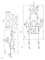
本実施形態では、検出回路の構成例について説明する。図4(A)〜図4(C)は、検出回路の構成例を示す図である。検出回路13は、先に図2(A)を用いて説明したように、例えば支持体100上の空きスペースに設けられ、かつ、信号処理回路10を内蔵する。図4(A)の例では、物理量センサー(ここでは静電容量型加速度センサーとする)に含まれる第1可変容量c1,第2可変容量c2は、共通の接地電極である固定電極208と、第1可動電極109aおよび第2可動電極109bと、を有している。
(Second Embodiment)
In this embodiment, a configuration example of the detection circuit will be described. 4A to 4C are diagrams illustrating a configuration example of the detection circuit. As described above with reference to FIG. 2A, the
検出回路13は、信号処理回路10と、CPU28と、インターフェース回路30と、を有する。信号処理回路10は、C/V変換回路(容量値/電圧変換回路)24と、アナログ校正&A/D変換回路26と、を有する。但し、この例は一例であり、信号処理回路10は、さらに、CPU28やインターフェース回路(I/F)30を含むことも可能である。
The
図4(B)の例では、第1可変容量c1,第2可変容量c2は、第1固定電極208aおよび第2固定電極208bと、共通の接地電極である可動電極109と、を有している。検出回路13の構成は、図4(A)の例と同じである。また、図4(C)の例では、第1可変容量c1および第2可変容量c2は、接地電位である第1固定電極208aおよび第2固定電極208bと、第1可動電極109aおよび第2可動電極109bと、を有している。検出回路13の構成は、図4(A)の例と同じである。
In the example of FIG. 4B, the first variable capacitor c1 and the second variable capacitor c2 include the first
(C/V変換回路の構成例)
ここで、図5(A)〜図5(C)を用いて、C/V変換回路(C/V変換アンプ)の構成と動作の一例について説明する。図5(A)〜図5(C)は、C/V変換回路の構成と動作について説明するための図である。
(C / V conversion circuit configuration example)
Here, an example of the configuration and operation of the C / V conversion circuit (C / V conversion amplifier) will be described with reference to FIGS. 5A to 5C are diagrams for explaining the configuration and operation of the C / V conversion circuit.
図5(A)は、スイッチトキャパシタを用いたC/V変換アンプ(チャージアンプ)の基本構成を示す図であり、図5(B)は、図5(A)に示されるC/V変換アンプの各部の電圧波形を示す図である。 5A is a diagram showing a basic configuration of a C / V conversion amplifier (charge amplifier) using a switched capacitor, and FIG. 5B is a C / V conversion amplifier shown in FIG. 5A. It is a figure which shows the voltage waveform of each part of these.
図5(A)に示すように、基本的なC/V変換回路24は、第1スイッチSW1および第2スイッチSW2(可変容量c1(またはc2)と共に入力部のスイッチトキャパシタを構成する)と、オペアンプ(OPA)1と、帰還容量(積分容量)Ccと、帰還容量Ccをリセットするための第3スイッチSW3と、オペアンプ(OPA)1の出力電圧Vcをサンプリングするための第4スイッチSW4と、ホールディング容量Chと、を有している。
As shown in FIG. 5A, the basic C /
また、図5(B)に示すように、第1スイッチSW1および第3スイッチSW3は同相の第1クロックでオン/オフが制御され、第2スイッチSW2は、第1クロックとは逆相の第2クロックでオン/オフが制御される。第4スイッチSW4は、第2スイッチSW2がオンしている期間の最後において短くオンする。第1スイッチSW1がオンすると、可変容量c1(c2)の両端には、所定の電圧Vdが印加されて、可変容量c1(c2)に電荷が蓄積される。このとき、帰還容量Ccは、第3スイッチがオン状態であることから、リセット状態(両端がショートされた状態)である。次に、第1スイッチSW1および第3スイッチSW3がオフし、第2スイッチSW2がオンすると、可変容量c1(c2)の両端は共に接地電位となるため、可変容量c1(c2)に蓄積されていた電荷が、オペアンプ(OPA)1に向けて移動する。このとき、電荷量が保存されるため、Vd・C1(C2)=Vc・Ccが成立し、よって、オペアンプ(OPA)1の出力電圧Vcは、(C1/Cc)・Vdとなる。すなわち、チャージアンプのゲインは、可変容量c1(あるいはc2)の容量値(C1またはC2)と、帰還容量Ccの容量値との比によって決定される。次に、第4スイッチ(サンプリングスイッチ)SW4がオンすると、オペアンプ(OPA)1の出力電圧Vcが、ホールディング容量Chによって保持される。保持された電圧がVoであり、このVoがチャージアンプの出力電圧となる。 Further, as shown in FIG. 5B, the first switch SW1 and the third switch SW3 are controlled to be turned on / off by the first clock having the same phase, and the second switch SW2 is the first phase having the opposite phase to the first clock. On / off is controlled by two clocks. The fourth switch SW4 is turned on briefly at the end of the period in which the second switch SW2 is on. When the first switch SW1 is turned on, a predetermined voltage Vd is applied to both ends of the variable capacitor c1 (c2), and charges are accumulated in the variable capacitor c1 (c2). At this time, the feedback capacitor Cc is in a reset state (a state in which both ends are short-circuited) because the third switch is in an on state. Next, when the first switch SW1 and the third switch SW3 are turned off and the second switch SW2 is turned on, both ends of the variable capacitor c1 (c2) are both at the ground potential, and therefore are stored in the variable capacitor c1 (c2). The transferred electric charge moves toward the operational amplifier (OPA) 1. At this time, since the charge amount is preserved, Vd · C1 (C2) = Vc · Cc is established, and therefore the output voltage Vc of the operational amplifier (OPA) 1 becomes (C1 / Cc) · Vd. That is, the gain of the charge amplifier is determined by the ratio between the capacitance value (C1 or C2) of the variable capacitor c1 (or c2) and the capacitance value of the feedback capacitor Cc. Next, when the fourth switch (sampling switch) SW4 is turned on, the output voltage Vc of the operational amplifier (OPA) 1 is held by the holding capacitor Ch. The held voltage is Vo, and this Vo becomes the output voltage of the charge amplifier.
先に説明したように、C/V変換回路24は、実際は、2つの可変容量(第1可変容量c1,第2可変容量c2)の各々からの差動信号を受ける。この場合には、C/V変換回路24として、例えば、図5(C)に示されるような、差動構成のチャージアンプを使用することができる。図5(C)に示されるチャージアンプでは、入力段において、第1可変容量c1からの信号を増幅するための第1のスイッチトキャパシタアンプ(SW1a,SW2a,OPA1a,Cca,SW3a)と、第2可変容量c2からの信号を増幅するための第2のスイッチトキャパシタアンプ(SW1b,SW2b,OPA1b,Ccb,SW3b)と、が設けられる。そして、オペアンプ(OPA)1aおよび1bの各出力信号(差動信号)は、出力段に設けられた差動アンプ(OPA2,抵抗R1〜R4)に入力される。
As described above, the C /
この結果、増幅された出力信号Voが、オペアンプ(OPA)2から出力される。差動アンプを用いることによりベースノイズ(同相ノイズ)を除去できるという効果が得られる。なお、以上説明したC/V変換回路24の構成例は一例であり、この構成に限定されるものではない。
As a result, the amplified output signal Vo is output from the operational amplifier (OPA) 2. By using the differential amplifier, an effect of removing base noise (in-phase noise) can be obtained. The configuration example of the C /
(第3実施形態)
本実施形態では、2つの異なる方向の加速度を検出することができる静電容量型センサーの一例について説明する。以下の説明では、静電容量型加速度センサーについて説明する。
(Third embodiment)
In the present embodiment, an example of a capacitive sensor capable of detecting accelerations in two different directions will be described. In the following description, a capacitive acceleration sensor will be described.
本実施形態では、Z軸方向の加速度を、揺動体のシーソー揺動による、Z軸方向の加速度検出用の可変容量の容量値変化に基づいて検出する。また、揺動体には、さらに、X軸方向またはY軸方向の加速度検出用の可変容量が付加されており、このX軸方向またはY軸方向の加速度検出用の可変容量の容量値変化に基づいて、X軸方向またはY軸方向の加速度を検出することができる。 In the present embodiment, the acceleration in the Z-axis direction is detected based on the change in the capacitance value of the variable capacitor for detecting the acceleration in the Z-axis direction due to the seesaw rocking of the rocking body. Further, a variable capacitor for acceleration detection in the X-axis direction or the Y-axis direction is further added to the oscillator, and based on the change in the capacitance value of the variable capacitor for acceleration detection in the X-axis direction or Y-axis direction. Thus, the acceleration in the X-axis direction or the Y-axis direction can be detected.
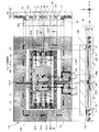
図6は、2つの異なる方向の加速度を検出することができる加速度センサーの構成の一例を示す図である。図6には、支持体100と蓋体200とによって構成される封止体の平面図と、長手方向(横方向)の断面図、長手方向に直交する方向(縦方向)の断面図が示されている。長手方向(横方向)の断面図は、平面図のA−A線に沿う断面図である。長手方向に直交する方向(縦方向)の断面図は、平面図のB−B線に沿う断面図である。
FIG. 6 is a diagram illustrating an example of a configuration of an acceleration sensor that can detect accelerations in two different directions. FIG. 6 shows a plan view of a sealing body constituted by the
図6の平面図において、蓋体200は、太線の一点鎖線で示されている。また、図6の平面図では、電極、配線ならびにパッド(外部接続端子)の配置例も記載してある。
In the plan view of FIG. 6, the
まず、3次元空間における方向を定義し、加速度センサーにおける各部の延在方向や、可変容量を構成する可動電極の変位の方向を明確化する。すなわち、揺動体300が水平な状態であるときの、水平面(揺動体300の主面が含まれる面ということもできる)内における揺動体の長手方向を第1方向(X軸方向)とする。水平面内における第1方向(X軸方向)に直交する方向(つまり、上記の水平面に直交する方向)を第2方向(Y軸方向)とし、第1方向(X軸方向)および第2方向(Y軸方向)の各々に直交する方向を第3方向(Z軸方向)とする。なお、X軸方向には、正のX軸方向(+X)および負のX軸方向(−X)が含まれる。この点については、Y軸方向ならびにZ軸方向についても同様である。
First, the direction in the three-dimensional space is defined, and the extending direction of each part in the acceleration sensor and the direction of displacement of the movable electrode constituting the variable capacitor are clarified. That is, when the
図6の例では、図1の例と同様に、揺動体300は、第1支持部40aおよび第2支持部40bによって、シーソー揺動自在に両持ち支持される。第1支持部40aは、第2方向(Y軸方向)に延在する第1トーションバネによって構成され、第2支持部40bは、第2方向(Y軸方向)に延在する第2トーションバネによって構成される。第1トーションバネ(第1支持部)40aの一端は揺動体300に連結(固定)され、かつ第1トーションバネ40aの他端は支持体100または蓋体200に連結(固定)される。第2トーションバネ(第2支持部)40bも同様に、その一端は揺動体300に連結(固定)され、かつ第2トーションバネ40bの他端は、支持体100または蓋体200に連結(固定)される。また、第1トーションバネ40aおよび第2トーションバネ40bの各々は、第2方向(Y軸方向)に延在する。例えば、第1トーションバネ40aおよび第2トーションバネ40bの各々は、平面視で、揺動体300の支持軸Q1に重なるように、第2方向(Y軸方向)に延在して設けられる。
In the example of FIG. 6, similarly to the example of FIG. 1, the rocking
揺動体300のシーソー揺動によって、可変容量c1,c2を構成する第1可動電極109aおよび第2可動電極109b(図6の例では、揺動体自体が共通電位の可動電極として機能する)と、第1固定電極208aおよび第2固定電極208bとの間の、第3方向(Z軸方向)の距離(電極間距離)が変化する。つまり、揺動体300のシーソー揺動を利用して、Z軸方向(鉛直方向)の加速度(重力加速度)を検出することができる。
The first
図6の例では、揺動体300には、さらに、第2方向(Y軸方向)の加速度を検出するための静電容量(第3容量c3および第4容量c4)が設けられている。第3容量c3および第4容量c4は、櫛歯電極によって構成される。以下、具体的に説明する。
In the example of FIG. 6, the
図6に示されるように、揺動体300は、さらに、第1支持部としての第1トーションバネ40aおよび第2支持部としての第2トーションバネ40bの各々に連結される枠体310と、第2方向(Y軸方向)に変位可能な第2方向変位用バネ(連結部ということもある)1a,1b,1c,1dを介して枠体310に連結されると共に、周囲に空洞部350が形成されている可動錘部313と、枠体310から空洞部350(あるいは可動錘部313)に向けて突出形成された固定電極部(第1腕状電極部ということがある)2a,2b,2c,2dと、可動錘部313から揺動体300(の枠体310)に向けて突出して形成され、可動錘部313と一体的に変位すると共に、固定電極部(第1腕状電極部)2a,2b,2c,2dに対向する可動電極部(第2腕状電極部ということがある)3a,3b,3c,3dと、を有する。固定電極部2a,2b,2c,2dならびに可動電極部3a,3b,3c,3dは、各々が櫛歯電極を構成し、各々の電極は、第1方向(X軸方向)に延在する。
As shown in FIG. 6, the
すなわち、揺動体300は開口部99(例えば、エッチングによって基板としての活性層106が除去されて形成される)を有し、その開口部99に、可動錘部313が配置されている。また、可動錘部313と揺動体300とを連結する連結部(第2方向変位用のバネ部あるいは弾性変形部)1a,1b,1c,1dが設けられている。また、揺動体300(の枠体310)から可動錘部313に向けて突出して形成された第1腕状電極部(固定電極部(2a,2b,2c,2d)と、可動錘部313から揺動体300に向けて突出して形成されると共に、第1腕状電極部(固定電極部)2a,2b,2c,2dに対向する第2腕状電極部(可動電極部)3a,3b,3c,3dと、を有する。
That is, the
また、第2方向変位用バネ1a,1b,1c,1dの各々は、アイソレーション領域ISO1,1SO4,ISO5,ISO8の各々によって、枠体310から電気的に分離されている。同様に、固定電極部2a,2b,2c,2dの各々は、アイソレーション領域ISO2,1SO3,ISO6,ISO7の各々によって、枠体310から電気的に分離されている。アイソレーション領域ISO1〜ISO8の各々は、例えば、シリコン単結晶に部分的に設けられた凹部に、SiO2等の絶縁膜を埋め込むことによって形成されている。
The second direction displacement springs 1a, 1b, 1c, and 1d are electrically separated from the
第2方向(X軸方向)の加速度によって、第2方向変位用バネ1a,1b,1c,1dが第2方向(Y軸方向)に変位すると、固定電極部2a,2b,2c,2dならびに可動電極部3a,3b,3c,3dとの間の距離(電極間距離)が変化し、第3容量c3および第4容量c4の容量値が変化する。この容量値の変化を、微小な電気信号(電流信号)の変化として検出することによって、第2方向(Y軸方向)の加速度を検出することができる。
When the second direction displacement springs 1a, 1b, 1c, 1d are displaced in the second direction (Y-axis direction) by the acceleration in the second direction (X-axis direction), the fixed
また、第2方向変位用バネ1a,1b,1c,1dは、例えば、第1方向(X軸方向)に直線状に延在する棒状のバネである。第2方向変位用バネ1a,1b,1c,1dは、例えば、SOI基板の活性層を構成するシリコン単結晶(ならびに層間絶縁膜や金属膜等を含む多層構造体)をパターニングして形成することができる。シリコン単結晶や多層構造体は、ある程度の弾性(ならびにある程度の剛性)を有することから、棒状にパターニングすることによって、弾性変形部材(弾性バネ)として使用することができる。揺動体300の製造方法としては、図3(A),図3(B)に示した方法を採用することができる。
The second direction displacement springs 1a, 1b, 1c, and 1d are, for example, rod-shaped springs that extend linearly in the first direction (X-axis direction). The second direction displacement springs 1a, 1b, 1c, and 1d are formed by patterning, for example, a silicon single crystal (and a multilayer structure including an interlayer insulating film, a metal film, etc.) that constitutes an active layer of the SOI substrate. Can do. Since silicon single crystals and multilayer structures have a certain degree of elasticity (and a certain degree of rigidity), they can be used as elastic deformation members (elastic springs) by patterning them into a rod shape. As a manufacturing method of the
このような構造をもつことによって、揺動体300は、第3方向(Z軸方向)の変位を検出するための第3方向検出プレートとしての役割の他、第2方向(Y軸方向)の変位を検出するための第2方向の検出プレートとしての役割も果たす。これによって、一つの揺動体300を用いて、異なる2つの方向の変位の各々に対応した静電容量の変化を検出することができる。これによって、例えば、異なる2つの方向(第3方向と第2方向)の加速度を検出することが可能な、小型かつ高機能な加速度センサーが実現される。
By having such a structure, the
次に、パッドおよび配線の配置について説明する。支持体100の周辺には、第1パッドPA1〜第5パッドPA5が設けられている。第1パッドPA1は、共通電位VCOM(GND)供給するためのパッドである。第2パッドPA2は、第1可変容量c1から得られる、Z軸方向の第1検出出力VZ1を外部に導出するためのパッドである。第2パッドPA2の代わりに、検出回路13(図2(A)参照)を設けて、可変容量c1から得られる、Z軸方向の第1検出出力VZ1を検出回路13に入力する構成としてもよい。この点については、他の検出信号についても同様である。
Next, the arrangement of pads and wiring will be described. Around the
第3パッドPA3は、第2方向(Y軸方向)の加速度を検出するための第3容量c3から得られる、Y軸方向の第1検出出力VY1を外部に導出するためのパッドである。第4パッドPA4は、第2方向(Y軸方向)の加速度を検出するための第4容量c4から得られる、Y軸方向の第2検出出力VY2を外部に導出するためのパッドである。第5パッドPA5は、第2可変容量c2から得られる、Z軸方向の第2検出出力VZ2を外部に導出するためのパッドである。 The third pad PA3 is a pad for deriving the first detection output VY1 in the Y-axis direction obtained from the third capacitor c3 for detecting the acceleration in the second direction (Y-axis direction). The fourth pad PA4 is a pad for deriving the second detection output VY2 in the Y-axis direction obtained from the fourth capacitor c4 for detecting the acceleration in the second direction (Y-axis direction) to the outside. The fifth pad PA5 is a pad for deriving the second detection output VZ2 in the Z-axis direction obtained from the second variable capacitor c2 to the outside.
また、揺動体300の一部である枠体310には、3本の配線L1(太線の細かな点線),L2(太線の粗い点線)、L3(太線の一点鎖線)が設けられている。配線L1は、揺動体300に、共通電位VCOM(GND)を供給するための配線である。また、配線L2は、第4容量c4から得られる、Y軸方向の第2検出出力VY2を外部に導出するための配線である。配線L3は、第3容量c3から得られる、Y軸方向の第1検出出力VY1を外部に導出するための配線である。また、電子回路を構成するために必要な、その他の配線L4〜L10が設けられている。
Further, the
図7(A),図7(B)は、図6に示される平面図および長手方向(横方向)の断面図を簡素化して示す図である。図7(A)は加速度センサーの平面図(蓋体は省略)であり、図7(B)は、図7(A)のA−A線に沿う断面図である。 FIGS. 7A and 7B are simplified views of the plan view and the cross-sectional view in the longitudinal direction (lateral direction) shown in FIG. 7A is a plan view of the acceleration sensor (the lid is omitted), and FIG. 7B is a cross-sectional view taken along the line AA in FIG. 7A.
先に説明したように、揺動体300は、第1シーソー片PT1と第2シーソー片PT2とを有する。揺動体300の一部である枠体310には、第1支持部(第1トーションバネ)40aの一端および第2支持部(第2トーションバネ)40bの一端が連結(固定)される。また、第1支持部(第1トーションバネ)40aの他端および第2支持部(第2トーションバネ)40bの他端は、支持体100に接続されている。
As described above, the rocking
揺動体300は、枠体310と、可動錘部313と、第2方向変位バネ(弾性変形部)1a〜1dと、固定電極部2a〜2dと、可動電極3a〜3dと、を有する。固定電極部2aと可動電極部3a、ならびに固定電極部2cと可動電極部3cによって、第3容量c3が構成される。同様に、固定電極部2bと可動電極部3b、ならびに固定電極部2dと可動電極部3dによって、第4容量c4が構成される。
The
本実施形態では、剛性を有する枠体310に第1トーションバネ40aおよび第2トーションバネ40bに接続される。よって、第1トーションバネ40aおよび第2トーションバネ40bによる第3方向(Z軸方向)の変位と、第2方向変位バネ1a〜1dによる第2方向(Y軸方向)の変位とが互いに干渉することが抑制される(各バネの変位が相互に独立しているとみなすことができる)。したがって、検出精度への悪影響は十分に低減される。これによって、例えば、異なる2つの方向(Y軸方向ならびにZ軸方向)の加速度を検出することが可能な、小型かつ高機能な加速度センサーが実現される。
In the present embodiment, the
(第4実施形態)
本実施形態では、第1方向(X軸方向)、第2方向(Y軸方向)および第3方向(Z軸方向)の各々の容量値の変化を検出することができる、3軸感度をもつ物理量センサーについて説明する。図8は、第1方向(X軸方向)、第2方向(Y軸方向)および第3方向(Z軸方向)の各々の容量値の変化を検出することができる、3軸感度をもつ物理量センサーの構成例を示す平面図である。図8において、前掲の実施形態と共通する要素には同じ参照符号を付している。以下の説明では、加速度センサーを例にとって説明する。
(Fourth embodiment)
In this embodiment, it has a triaxial sensitivity that can detect changes in capacitance values in the first direction (X-axis direction), the second direction (Y-axis direction), and the third direction (Z-axis direction). The physical quantity sensor will be described. FIG. 8 is a physical quantity having triaxial sensitivity that can detect changes in capacitance values in the first direction (X-axis direction), the second direction (Y-axis direction), and the third direction (Z-axis direction). It is a top view which shows the structural example of a sensor. In FIG. 8, the same reference numerals are given to elements common to the above-described embodiment. In the following description, an acceleration sensor will be described as an example.
図8に示される加速度センサーでは、揺動体300は、第1支持部としての第1トーションバネ40aおよび第2支持部としての第2トーションバネ40bの各々に連結される枠体310と、第1方向(X軸方向)および第2方向(Y軸方向)の各方向に変位可能な、第1方向および第2方向変位用バネ11a〜11dと、第1方向および第2方向変位用バネ11a〜11dの各々を介して枠体310に連結されると共に、周囲に空洞部350が形成されている可動錘部313と、枠体310から空洞部350に向けて突出形成された固定電極部2a,2b,2c,2d,2a’,2b’,2c’,2d’と、可動錘部313と一体的に変位すると共に、固定電極部2a,2b,2c,2d,2a’,2b’,2c’,2d’の各々に対向する可動電極部3a,3b,3c,3d,3a’,3b’,3c’,3d’と、を有する。
In the acceleration sensor shown in FIG. 8, the
主要な構成は、図6および図7に示される実施形態にかかる物理量センサーの構成と同様である。但し、図6および図7の例では、第2方向変位バネを使用していたのに対して、本実施形態では、第1方向(X軸方向)および第2方向(Y軸方向)の各方向に変位可能な、第1方向および第2方向変位用バネ11a〜11dを使用する。第1方向および第2方向変位用バネ11a〜11dの各々は、平面視で、四角形の枠体310の四隅から、枠体310と略45度の角度をなす方向に延在する。
The main configuration is the same as the configuration of the physical quantity sensor according to the embodiment shown in FIGS. 6 and 7. However, in the example of FIGS. 6 and 7, the second direction displacement spring is used, whereas in the present embodiment, each of the first direction (X axis direction) and the second direction (Y axis direction). The first direction and second direction displacement springs 11a to 11d that can be displaced in the direction are used. Each of the first direction and second direction displacement springs 11a to 11d extends from the four corners of the
本実施形態では、第3方向(Z軸方向)加速度の検出用の第1可変容量c1,第2可変容量c2と、第2方向(Y軸方向)加速度の検出用の第3容量c3,第4容量c4と、第1方向(X軸方向)加速度の検出用の第5容量c3’,第6容量c4’と、を有する。 In the present embodiment, the first variable capacitor c1 and the second variable capacitor c2 for detecting the third direction (Z-axis direction) acceleration, the third capacitor c3 for detecting the second direction (Y-axis direction) acceleration, and the second 4 capacitors c4, and a fifth capacitor c3 ′ and a sixth capacitor c4 ′ for detecting acceleration in the first direction (X-axis direction).
本実施形態では、剛性を有する枠体310に第1トーションバネ40aおよび第2トーションバネ40bが接続される。よって、第1トーションバネ40aおよび第2トーションバネ40bによる第3方向(Z軸方向)の変位と、第1方向および第2方向変位バネ11a〜11dによる第1方向(X軸方向)または第2方向(Y軸方向)の変位とが互いに干渉することが抑制される(各変位が相互に独立しているとみなすことができる)。よって、検出精度への悪影響は十分に低減される。これによって、例えば、異なる3つの方向(第1方向〜第3方向の各々)の加速度を検出することが可能な、小型かつ高機能な加速度センサーが実現される。
In the present embodiment, the
(第5実施形態)
本実施形態では、2つの異なる方向の加速度を検出することができる静電容量型加速度センサーの他の例について説明する。以下の説明では、静電容量型加速度センサーについて説明する。
(Fifth embodiment)
In the present embodiment, another example of a capacitive acceleration sensor capable of detecting acceleration in two different directions will be described. In the following description, a capacitive acceleration sensor will be described.
図9は、2つの異なる方向の加速度を検出することができる加速度センサーの構成の他の例を示す図である。図9において、前掲の実施形態の例と共通する部分には同じ参照符号を付している。 FIG. 9 is a diagram illustrating another example of a configuration of an acceleration sensor that can detect accelerations in two different directions. In FIG. 9, the same reference numerals are given to parts common to the above-described embodiment example.
先に説明した図6ならびに図7の例では、第1トーションバネ40aおよび第2トーションバネ40bを枠体310に連結していたが、本実施形態では、枠体を使用せず、第2方向(Y軸方向)に変位可能な第2方向変位用バネ1e,1fに、第1トーションバネ40aおよび第2トーションバネ40bの各々を直接に連結されている。第3容量c3および第4容量c4が設けられるのは、図6ならびに図7の例と同じである。
In the example of FIGS. 6 and 7 described above, the
本実施形態によれば、例えば、異なる2つの方向(第3方向と第2方向)の加速度を検出することが可能な、高機能な加速度センサーが実現される。さらに、枠体を省略することができることから、より一層の小型化(占有面積の削減)が可能である。 According to the present embodiment, for example, a highly functional acceleration sensor that can detect accelerations in two different directions (third direction and second direction) is realized. Furthermore, since the frame body can be omitted, further downsizing (reduction of occupied area) is possible.
(第6実施形態)
図10は、図6および図7に示される構造の揺動体を2個使用して、異なる3つの方向の加速度を検出可能とした物理量加速度センサーの構成を示す平面図である。図10の例では、共通の支持体100に、揺動体300と、揺動体300’とが設けられる。揺動体300および揺動体300’の構成は、図6および図7に示される揺動体300の構成と同じである。なお、揺動体300’の構成要素の参照符号には、ダッシュ記号が付されている。
(Sixth embodiment)
FIG. 10 is a plan view showing a configuration of a physical quantity acceleration sensor that can detect accelerations in three different directions by using two oscillators having the structure shown in FIGS. 6 and 7. In the example of FIG. 10, the rocking
揺動体300の支持軸Q1は第2方向(Y軸方向)に延在している。揺動体300’の支持軸Q1’は第1方向(X軸方向)に延在している。揺動体300は、先に説明したように、第3方向(Z方向)の加速度を検出するための検出プレートとしての機能と、第2方向(Y方向)の加速度を検出するための検出プレートとしての機能とを併せ持つ。一方、揺動体300’は、第3方向(Z方向)の加速度を検出するための検出プレートとしての機能と、第1方向(X方向)の加速度を検出するための検出プレートとしての機能とを併せ持つ。
The support shaft Q1 of the rocking
本実施形態によれば、第1方向(X軸方向)の加速度、第2方向(Y軸方向)の加速度ならびに第3方向(Z軸方向)の加速度を検出することが可能な、高機能な物理量センサー(加速度センサー)を実現することができる。 According to the present embodiment, it is possible to detect acceleration in the first direction (X-axis direction), acceleration in the second direction (Y-axis direction), and acceleration in the third direction (Z-axis direction). A physical quantity sensor (acceleration sensor) can be realized.
(第7実施形態)
本実施形態では、シーソー構造を利用した物理量センサーの検出精度を、より向上させるための信号処理方法と、その信号処理方法を利用した物理量センサーの構成について説明する。
(Seventh embodiment)
In the present embodiment, a signal processing method for further improving the detection accuracy of a physical quantity sensor using a seesaw structure and a configuration of the physical quantity sensor using the signal processing method will be described.
図11(A)〜図11(H)は、シーソー構造を利用した物理量センサーの検出精度を、より向上させるための信号処理方法について説明するための図である。図11(A)は、揺動体300が水平状態を維持している状態(Z軸方向加速度が0Gである状態)を示している。図11(B)では、Z軸方向加速度が1Gであるときの揺動体300の状態を示している。図11(B)における揺動体300は、第1シーソー片PT1の回転モーメントと第2シーソー片PT2の回転モーメントの不均衡によって傾いた状態となっている(重力加速度が加わっているにも関わらず、揺動体300が水平状態を保っていたのでは、重力加速度を検出できないからである)。
FIG. 11A to FIG. 11H are diagrams for explaining a signal processing method for further improving the detection accuracy of the physical quantity sensor using the seesaw structure. FIG. 11A shows a state where the
この状態で、揺動体300に、揺動体300の延在方向である第1方向(X軸方向)の加速度が作用した場合を想定する(図11(C)参照)。図11(C)に示されるように、傾いている揺動体300に対して第1方向(X軸方向:水平時の揺動体の延在方向)の加速度Gが作用すると、揺動体300には、第1方向(X軸方向)の加速度Gの向きとは逆向きに慣性力F’が働く(慣性力の大きさは、第1方向の加速度Gに比例する)。この慣性力F’は、傾いている揺動体300を回転させる力(つまり、傾いている揺動体300に垂直に働く力)の成分を有することから、揺動体300の傾きが変化する(図11(D)参照)。つまり、実際には第3方向の加速度は変化していないにもかかわらず、第1方向の加速度(検出方向(第3方向)とは異なる方向の加速度)Gによって、見かけ上、第3方向の加速度が変化したことになる。このような検出方向とは異なる方向に検出感度をもつことは、物理量センサーの検出精度の低下の原因となる。
In this state, it is assumed that acceleration in the first direction (X-axis direction) that is the extending direction of the rocking
この問題点について具体的に説明する。図11(D)に示されるように、同じ大きさの慣性力F’が、揺動体300の、第1シーソー片(第1の領域)PT1および第2シーソー片(第2の領域)PT2の各々に作用する。第1シーソー片PT1に加わる慣性力F’は、揺動体300の延長線の方向の力成分Fa1と、揺動体300に垂直な方向の力成分Fb1とに分けることができる。同様に、第2シーソー片PT1に作用する慣性力F’は、揺動体300の延長線の方向の力成分Fa2と、揺動体300に垂直な方向の力成分Fb2とに分けることができる。第1シーソー片PT1に作用する揺動体300に垂直な方向の力成分Fb1は、揺動体300の第1シーソー片PT1に対して、反時計回りのモーメントを生じさせる。一方、第2シーソー片PT2に作用する揺動体300に垂直な方向の力成分Fb2は、揺動体300の第2シーソー片PT2に対して、時計回りのモーメントを生じさせる。力成分Fb1と力成分Fb2の大きさは同じである。
This problem will be specifically described. As shown in FIG. 11D, the inertia force F ′ of the same magnitude is applied to the first seesaw piece (first region) PT1 and the second seesaw piece (second region) PT2 of the rocking
但し、図11(D)の例では、第1シーソー片PT1の腕の長さに比べて第2シーソー片PT2の腕の長さの方が長い(つまり、第2シーソー片PT2の質量の方が重い)ことから、回転モーメントに差が生じる。つまり、腕が長い第2シーソー片PT2に作用する時計回りの回転モーメントが優勢となり、その結果、揺動体300全体が、時計回りに回転することになる。この時計回りの回転モーメントは、傾いている揺動体300に対して第1方向(X軸方向:水平時の揺動体の延在方向)の加速度Gが作用することによって生じる、見かけ上の回転モーメントということができる。
However, in the example of FIG. 11D, the arm length of the second seesaw piece PT2 is longer than the arm length of the first seesaw piece PT1 (that is, the mass of the second seesaw piece PT2 is larger). Difference in rotational moment. That is, the clockwise rotational moment acting on the second seesaw piece PT2 having a long arm becomes dominant, and as a result, the
また、図11(E)に示すような揺動体300(図11(D)の例とは傾きの方向が逆になっている)に、慣性力F’が作用したときも、同様の理由によって見かけ上の回転モーメントが発生して、揺動体300の傾きが変化する。図11(B)において、第1シーソー片PT1に作用する揺動体300に垂直な方向の力成分Fb1は、揺動体300の第1シーソー片PT1に対して、時計回りのモーメントを生じさせる。一方、第2シーソー片PT2に作用する揺動体300に垂直な方向の力成分Fb2は、揺動体300の第2シーソー片PT2に対して、反時計回りのモーメントを生じさせる。力成分Fb1と力成分Fb2の大きさは同じである。
Further, when the inertial force F ′ is applied to the rocking
但し、図11(E)の例では、第1シーソー片PT1の腕の長さの方が、第2シーソー片PT2の腕の長さよりも長い(つまり、第1シーソー片PT1の質量の方が重い)ことから、回転モーメントに差が生じる。つまり、腕が長い第1シーソー片PT1に作用する時計回りの回転モーメントが優勢となり、その結果、揺動体300全体が、時計回りに回転することになる。つまり、図11(D)の例と同様に、見かけ上の時計回りの回転モーメントによって、揺動体300の傾斜が変化する。
However, in the example of FIG. 11E, the arm length of the first seesaw piece PT1 is longer than the arm length of the second seesaw piece PT2 (that is, the mass of the first seesaw piece PT1 is greater). A difference in rotational moment. That is, the clockwise rotational moment acting on the first seesaw piece PT1 having a long arm becomes dominant, and as a result, the
ここで、図11(D)の例と、図11(E)の例とを比較する。図11(D)の例では、見かけ上の回転モーメントによって、揺動体300は、その傾斜がより深くなるように回転する。例えば、見かけ上の回転モーメントが生じる前の傾斜角(水平線と揺動体とがなす角度)をθとしたとき、見かけ上の回転モーメントによって傾斜が変化した後の傾斜角は、θ+δθとなる。一方、図11(D)の例では、見かけ上の回転モーメントによって、揺動体300は、傾斜している揺動体が押し戻されて、その傾斜角が浅くなるように回転する。例えば、見かけ上の回転モーメントが生じる前の傾斜角(水平線と揺動体とがなす角度)をθとしたとき、見かけ上の回転モーメントによって傾斜が変化した後の傾斜角は、θ−δθとなる。
Here, the example of FIG. 11D is compared with the example of FIG. In the example of FIG. 11D, the
つまり、揺動体300が傾斜している方向を基準として考えると、図11(D)の例における見かけ上の回転モーメントの方向と、図11(E)の例における見かけ上の回転モーメントの方向とは互いに逆向きである。例えば、揺動体300が傾斜している方向を正の方向としたとき、図11(D)の例における見かけ上の回転モーメントの方向は正の方向であり、図11(E)の例における見かけ上の回転モーメントの方向は負の方向となる。つまり、図11(D)および図11(E)において、見かけ上の回転モーメントによって、揺動体300は同じ角度だけ回転するが、その方向が逆である。本実施形態では、この点に着目し、図11(D)の構造をもつ揺動体300aと、図11(E)の構造をもつ揺動体300bとを併用し、各揺動体から得られる信号を基礎として所定の演算を実行し、これによって、見かけ上の回転モーメントによって生じる誤差を抑制する。
That is, when the direction in which the
すなわち、本実施形態では、図11(F)に示すように、2つの揺動体(つまり第1揺動体300aおよび第2揺動体300b)を設ける。そして、先に説明した信号処理回路(図3の参照符号10)が、各揺動体300a,300bから得られる信号に基づいて、検出誤差を補償するための信号処理を実行して検出誤差を抑制する。
That is, in this embodiment, as shown in FIG. 11F, two oscillating bodies (that is, the first
ここで、第1揺動体300aは、図11(D)に示される揺動体に対応する。第2揺動体300bは、図11(E)に示される揺動体に対応する。第1揺動体300aは、第1シーソー片(第1の領域)PT1aおよび第2シーソー片(第2の領域)PT2aを有する。第2揺動体300bは、第3シーソー片(第3の領域)PT1bおよび第4シーソー片PT2b(第4の領域)を有する。
Here, the
すなわち、第1揺動体300aは、平面視で、支持軸Q1(第1軸)によって第1の領域(第1シーソー片)PT1aと第2の領域(第2シーソー片)PT2とに区画される。また、第2揺動体300bは、平面視で支持軸Q2(第2軸)によって第3の領域(第3シーソー片PT1b)と第4の領域(第4シーソー片PT2b)とに区画されている。
In other words, the
本実施例においては、第1揺動体300aと第2揺動体300bとは互いに鏡像に配置している。「鏡像に配置」とは、例えば図12の平面図に示すような配置をいう。ここで、図12を参照する。図12において、第2揺動体300bは、平面視で、第1の領域(第1シーソー片)PT1aと第2の領域(第2シーソー片)PT2aの並び方向に直交する軸LXに対し、第1揺動体300aを反転させた(折り返した)形状である。
In the present embodiment, the first
図11(F)〜図11(H)に戻って説明を続ける。図11(F)および図11(G)において、第2の領域(第2シーソー片)PT2aの質量は、第1の領域(第1シーソー片)PT1aの質量よりも重く(腕の長さが長いため)、また、第4の領域(第4シーソー片PT2b)の質量は、第3の領域(第3シーソー片PT1b)の質量よりも軽い(腕の長さが短いため)。 Returning to FIG. 11 (F) to FIG. 11 (H), the description will be continued. 11 in (F) and FIG. 11 (G), the length of the mass of the second region (second seesaw piece) PT2 a is heavier than the mass of the first region (first seesaw piece) PT1a (arm The mass of the fourth region (fourth seesaw piece PT2b) is lighter than the mass of the third region (third seesaw piece PT1b) (because the length of the arm is short ).
また、第1の領域(第1シーソー片)PT1aと第2の領域(第2シーソー片)PT2の並び方向と、第3の領域(第3シーソー片PT1b)と第4の領域(第4シーソー片PT2b)の並びの方向とは、互いに同じである。また、重力を受けた状態においては、先に、図11(D),図11(E)の例で説明したとおり、第1揺動体300aおよび第2揺動体300bは互いに反対向きに傾斜している(図11(G)参照)。
Also, the arrangement direction of the first region (first seesaw piece) PT1a and the second region (second seesaw piece) PT2, the third region (third seesaw piece PT1b) and the fourth region (fourth seesaw piece). The direction of arrangement of the pieces PT2b) is the same as each other. Further, in the state of being subjected to gravity, as described above with reference to FIGS. 11D and 11E, the first
第1揺動体300a、第2揺動体300bの各々によって、2つの可変容量が形成されるため、合計で4個の可変容量が設けられることになる。図11(F)の状態では、第1揺動体300aおよび第2揺動体300bは水平状態であり、4つの可変容量の各々の容量値はC0である。
Since each of the first
ここで、検出信号として、第1揺動体300aの第1シーソー片(第1の領域)PT1aの変位に基づいて変動する第1検出信号と、第1揺動体300aの第2シーソー片(第2の領域)PT2aの変位に基づいて変動する第2検出信号と、第2揺動体300bの第3シーソー片(第3の領域)PT1bの変位に基づいて変動する第3検出信号と、第2揺動体300bの第4シーソー片(第4の領域)PT2bの変位に基づいて変動する第4検出信号と、が出力されるとする。
Here, as the detection signal, a first detection signal that fluctuates based on the displacement of the first seesaw piece (first region) PT1a of the first
以下の説明では、第1検出信号および第2検出信号を差動出力1と表現し、また、第3出信号および第4出信号を差動出力2と表現する。図11(F)の状態では、差動出力1は(C0,C0)となり、差動出力2も(C0,C0)となる。
In the following description, the first detection signal and the second detection signal are expressed as a
重力加速度(1G)がある状態では、図11(G)に示すように、第1揺動体300aおよび第2揺動体300bの各々は、回転モーメントを受けて傾く。
In a state where there is a gravitational acceleration (1G), as shown in FIG. 11G, each of the first
ここで、第1揺動体300aと第2揺動体300bは共に第1方向(X軸方向)に延在するが、第1揺動体300aの傾きの向きと、第2揺動体300bの傾きの向きは互いに反対向きであり、かつ、水平面を基準とした回転角の絶対値は同じである。例えば、第1揺動体300aは時計回りに、水平面を基準として+θだけ傾いており、一方、第2揺動体300bは反時計回りに、水平面を基準として−θだけ傾いている。
Here, both the first
図11(G)の状態では、差動出力1は、(C0+ΔC,C0−ΔC)となる。差動出力2は、(C0−ΔC,C0+ΔC)となる。ΔCは、揺動体300a,300bが傾いたことによる各容量の容量値の変化分を示す。
In the state of FIG. 11G, the
この状態で、図11(C)の場合と同様に、第1方向(X軸方向)の加速度Gが加わり、その反対方向に慣性力F’が働いた場合を想定する。この場合、第1揺動体300aおよび第2揺動体300bの各々には、図11(H)に示すような傾きが生じる。つまり、第1揺動体300aには、図11(D)に示したように、時計回りの見かけ上の回転モーメントが生じる。一方、第2揺動体300bにも同様に、図11(E)に示したように、見かけ上の時計回りの回転モーメントが生じる。但し、揺動体300a,300bの各々が傾斜している方向を基準として考えると、第1揺動体300aに生じる見かけ上の回転モーメントの方向と、第2揺動体300bに生じる見かけ上の回転モーメントの方向とは、互いに逆向きである(前者は第1揺動体300aの傾きが増大する方向、後者は、第2揺動体300bの傾きが減少する方向である)。第1揺動体300aに生じる見かけ上の回転モーメントと、第2揺動体300bに生じる見かけ上の回転モーメントは、同じ大きさで、かつ、方向が逆である。
In this state, as in the case of FIG. 11C, it is assumed that the acceleration G in the first direction (X-axis direction) is applied and the inertial force F ′ is applied in the opposite direction. In this case, each of the first
したがって、第1揺動体300aおよび第2揺動体300bの各々には、図11(H)に示すような傾きが生じる。ここで、第1検出信号に重畳されている見かけ上の回転力による誤差変位に起因する可変容量(静電容量)の容量値の変動分を例えば「+δC」としたとき、第2検出信号に関する容量値の変動分は「−δC」となり、同様に、第3検出信号に重畳されている見かけ上の回転力による誤差変位に起因する可変容量(静電容量)の容量値の変動分は「+δC」であり、第4検出信号に関する容量値の変動分は「−δC」となる。
Therefore, each of the first
つまり、図11(G)の状態では、差動出力1は、(C0+ΔC+δC,C0−ΔC−δC)となる。また、差動出力2は、(C0−ΔC+δC,C0+ΔC−δC)となる。
That is, in the state of FIG. 11G, the
信号処理回路において、第1差動出力1に基づいて、第1検出信号と第2検出信号との差を示す第1差動信号を生成すると、第1差動信号は2(ΔC+δC)となる。つまり、第1差動信号に重畳する、見かけ上の回転力による誤差変位に起因する可変容量(静電容量)の容量値の変動分は、「2δC(=+δC−(−δC))」となる。
In the signal processing circuit, when the first differential signal indicating the difference between the first detection signal and the second detection signal is generated based on the first
また、第4検出信号と第3検出信号との差を示す第2差動信号が生成されると、第2差動信号は、2(ΔC−δC)となる。つまり、第2差動信号に重畳する、見かけ上の回転力による誤差変位に起因する可変容量(静電容量)の容量値の変動分は、「−2δC(=−δC−(+δC))」となる。 Further, when the second differential signal indicating the difference between the fourth detection signal and the third detection signal is generated, the second differential signal becomes 2 (ΔC−δC). That is, the variation of the capacitance value of the variable capacitance (capacitance) caused by the error displacement due to the apparent rotational force superimposed on the second differential signal is “−2δC (= −δC − (+ δC))”. It becomes.
そして、信号処理回路が、第1差動信号と第2差動信号とを加算すると、第1差動信号に重畳する誤差成分「+2δC」と、第2差動信号に重畳する誤差成分「−2δC」とが相殺されて、誤差がキャンセルされる。 Then, when the signal processing circuit adds the first differential signal and the second differential signal, an error component “+ 2δC” superimposed on the first differential signal and an error component “−” superimposed on the second differential signal. 2δC ”is canceled out and the error is cancelled.
なお、第1差動信号と第2差動信号とが加算されると、信号振幅が必要以上に大きくなる場合がある。このことが問題となる場合には、第1差動信号と第2差動信号とを加算して得られる信号の振幅を、例えば半分にする信号処理(つまり、(第1差動信号1+第2差動信号)/2)等を適宜、行うこともできる。
Note that when the first differential signal and the second differential signal are added, the signal amplitude may increase more than necessary. If this becomes a problem, the signal processing obtained by adding the first differential signal and the second differential signal, for example, halving the amplitude of the signal (that is, (first
すなわち、信号処理回路が、第1検出信号と第2検出信号との差を示す第1差動信号を生成し、また、第3検出信号と第4検出信号との差を示す第2差動信号を生成し、第1差動信号と第2差動信号を加算して得られる信号に基づいて、第1方向の加速度に基づく誤差が抑制された、第3方向の加速度検出信号を生成することが可能である。 That is, the signal processing circuit generates a first differential signal indicating a difference between the first detection signal and the second detection signal, and also indicates a second differential indicating the difference between the third detection signal and the fourth detection signal. A signal is generated, and an acceleration detection signal in the third direction in which an error based on the acceleration in the first direction is suppressed is generated based on a signal obtained by adding the first differential signal and the second differential signal. It is possible.
このようにし、本実施形態の信号処理方法によれば、検出方向以外の方向に検出感度をもつことによる誤差を、信号処理によってキャンセルすることができる。よって、シーソー構造を利用した物理量センサーの第3方向の加速度等の検出精度を、より向上させることができる。 Thus, according to the signal processing method of the present embodiment, an error caused by having detection sensitivity in a direction other than the detection direction can be canceled by signal processing. Therefore, the detection accuracy such as acceleration in the third direction of the physical quantity sensor using the seesaw structure can be further improved.
図12は、図11に示される信号処理方法を採用した物理量センサーの構成の一例を示す図である。図12の物理量センサーは、第1シーソー構造体ST1と、第2シーソー構造体ST2と、第1シーソー構造体ST1および第2シーソー構造体ST2の各々から出力される検出信号に基づいて、所定の信号処理を実行する信号処理回路10と、を有している。
FIG. 12 is a diagram illustrating an example of a configuration of a physical quantity sensor that employs the signal processing method illustrated in FIG. 11. The physical quantity sensor of FIG. 12 is based on detection signals output from each of the first seesaw structure ST1, the second seesaw structure ST2, the first seesaw structure ST1, and the second seesaw structure ST2. And a
信号処理回路10は、スイッチトキャパシタキャパシタアンプ(SCA:図5参照)と、差動増幅器25a,25bと、平均演算器(または加算演算器)27と、を有する。スイッチトキャパシタキャパシタアンプSCAならびに差動増幅器25a,25bは、図4に示されるC/V変換回路24に対応する。また、平均演算器(または加算演算器)27は、例えば、図4に示されるアナログ校正&A/D変換回路26に含まれる。
The
また、第1シーソー構造体ST1は、第1揺動体300aと、第1揺動体300aを、第1支持軸Q1(第1軸)を支点としてシーソー揺動可能に両持ち支持する、第1揺動体用の第1支持部40a1および第1揺動体用の第2支持部40b1と、第1揺動体300aのシーソー揺動に応じて位置が変化する第1揺動体用の第1可動電極109a1,109b1と、第1揺動体用の可動電極109a1,109b1に対向する位置に設けられる第1揺動体用の固定電極(不図示)と、を有する第1可変容量部(不図示)と、を有する。
Further, the first seesaw structure ST1 supports the
そして、第1揺動体300aは、平面視で第1支持軸Q1によって区画される2つの部分のうちの一方に対応する第1揺動体の第1シーソー片(第1領域)PT1aと、2つの部分のうちの他方に対応する第1揺動体300aの第2シーソー片(第2領域)PT2aと、を有する。
The
また、第2シーソー構造体ST2は、第2揺動体300bと、第2揺動体300bを、第2支持軸Q2(第2軸)を支点としてシーソー揺動可能に両持ち支持する、第2揺動体用の第1支持部40a2および第2揺動体用の第2支持部40b2と、第2揺動体300bのシーソー揺動に応じて位置が変化する第2揺動体用の可動電極(不図示)と、第2揺動体用の可動電極に対向する位置に設けられる第2揺動体用の固定電極(不図示)と、を有する第2可変容量部(不図示)と、を有する。
Further, the second seesaw structure ST2 supports the
第2揺動体300bは、平面視で第2支持軸Q2(第2軸)によって区画される2つの部分のうちの一方に対応する第3シーソー片(第3領域)PT1bと、2つの部分のうちの他方に対応する第2シーソー片(第4領域)PT2bと、を有し、平面視における第1揺動体300aの長手方向ならびに第2揺動体300bの長手方向を第1方向(例えばX軸方向)とし、平面視における第1方向に直交する方向を第2方向(例えばY軸方向)とし、第1方向および第2方向の各々に直交する方向を第3方向(例えばZ軸方向)としたとき、第3方向の同じ大きさの加速度が第1揺動体300aおよび第2揺動体300bの各々に作用している状態における、第1揺動体300aの傾きの向きと、第2揺動体300bの傾きの向きは互いに反対向きであり、また、第1揺動体300aおよび第2揺動体300bの各々の、水平面を基準とした回転角の絶対値は同じである。
The
そして、第1シーソー構造体ST1からは、検出信号として、第1揺動体300aの第1シーソー片PT1aの変位に基づいて変動する第1検出信号VZ1と、第1揺動体300aの第2シーソー片PT2aの変位に基づいて変動する第2検出信号VZ2と、が出力される。また、第2シーソー構造体ST2からは、検出信号として、第2揺動体300bの第3シーソー片(第3の領域)PT1bの変位に基づいて変動する第3検出信号VZ3と、第2揺動体300bの第4シーソー片(第4領域)PT2bの変位に基づいて変動する第4検出信号VZ4と、が出力される。
Then, from the first seesaw structure ST1, a first detection signal VZ1 that varies based on the displacement of the first seesaw piece PT1a of the
信号処理回路10に含まれる差動増幅器25aは、第1検出信号VZ1と第2検出信号VZ2との差を示す第1差動信号DS1を生成する。また、差動増幅器25bは、第4検出信号VZ4と第3検出信号VZ3との差を示す第2差動信号DS2を生成する。第1差動信号DS1および第2差動信号DS2は、平均演算器(または加算演算器)27に入力される。平均演算器(または加算演算器)27は、第1差動信号DS1と第2差動信号DS2を加算する処理を実行する。例えば、(DS1+DS2)、あるいは、((DS1+DS2)/2)というような信号処理が実行され、この結果として得られる信号に基づいて、第1方向(X軸方向)の加速度に基づく誤差が抑制された、第3方向(Z軸方向)の加速度等の検出信号DS3が生成される。検出信号DS3は、(DS1+DS2)、あるいは、((DS1+DS2)/2)というような信号処理の結果を示す信号そのものであってもよく、さらに、アナログ校正処理が施された後の信号であってもよい。
The
(第8実施形態)
図13は、物理量加速度センサーの他の例(図12の構成に、さらに、第1方向(X軸方向)の加速度を検出するための構成を追加した例)を示す平面図である。図13の例では、図12の構成に加えて、第1方向(X軸方向)の加速度を検出するための静電容量型物理量センサー370が追加されている。この物理量加速度センサー370は、第1方向(X軸方向)の加速度を検出するための機能のみを有し、シーソー揺動による第3方向(Z軸方向)の加速度を検出する機能は有していない(一対の揺動体300a,300bを用いて、高精度に第3方向の加速度を検出することができるため、それ以上、揺動体を設ける必要がないからである)。
(Eighth embodiment)
FIG. 13 is a plan view showing another example of the physical quantity acceleration sensor (an example in which a configuration for detecting acceleration in the first direction (X-axis direction) is further added to the configuration of FIG. 12). In the example of FIG. 13, in addition to the configuration of FIG. 12, a capacitance type physical quantity sensor 370 for detecting acceleration in the first direction (X-axis direction) is added. This physical quantity acceleration sensor 370 has only a function for detecting acceleration in the first direction (X-axis direction), and has a function for detecting acceleration in the third direction (Z-axis direction) due to seesaw rocking. No (because it is possible to detect the acceleration in the third direction with high accuracy using the pair of
第1方向(X軸方向)の加速度を検出するための加速度センサー370は、可動錘部313と、第1方向に変形可能なバネ1a,1b,1c,1dと、固定電極2a,2b,2a’,2b’と、可動電極3a,3b,3a’,3b’と、を有する。可動錘部313がX軸方向に変位すると、可動電極3a,3b,3a’,3b’も同様に変位し、固定電極2a,2b,2a’,2b’ならびに可動電極3a,3b,3a’,3b’の各々によって構成される可変容量の容量値が変化し、これに対応して電荷が移動し、微小な電気信号(電流信号)が生成される。したがって、その電気信号に基づいて、第1方向(X軸方向)の加速度を検出することができる。
The acceleration sensor 370 for detecting acceleration in the first direction (X-axis direction) includes a
図13の物理量センサーは、第1方向(X軸方向)の加速度ならびに第3方向(Z軸方向)の加速度を検出することができ、かつ、第3方向(Z軸方向)の加速度は、誤差補償処理によって、他軸感度に伴う誤差を抑制することが可能であることから、より高精度な第3方向(Z軸方向)の加速度の検出が可能である。 The physical quantity sensor of FIG. 13 can detect acceleration in the first direction (X-axis direction) and acceleration in the third direction (Z-axis direction), and the acceleration in the third direction (Z-axis direction) is an error. Since the compensation process can suppress an error due to the sensitivity of the other axis, it is possible to detect the acceleration in the third direction (Z-axis direction) with higher accuracy.
(第9実施形態)
以上の実施形態においては、揺動体の支持部を揺動体の中心を通る線と平行な位置にずらすことにより揺動体をシーソー揺動可能にしたが、これに限らず、種々、変形や応用が可能である。
(Ninth embodiment)
In the above embodiment, the rocking body can be rocked by seesaw rocking by shifting the support portion of the rocking body to a position parallel to the line passing through the center of the rocking body. However, the present invention is not limited to this, and various modifications and applications are possible. Is possible.
図15(A)〜図15(D)は、物理量センサーの構造の他の例を示す図である。図15において、前掲の図面と共通する部分には同じ参照符号を付している。図15(A),図15(B)の例では、揺動体300の一端に質量部900が設けられている。図15(A)は物理量センサー(センサー素子構造体)の断面図であり、図15(B)は、図15(A)に対応する、揺動体300の、平面視における構造を示す。質量部900が設けられることによって、例えば、第1シーソー片PT1と第2シーソー片PT2の長手方向の長さが同じである場合であっても、揺動体300をシーソー揺動させることができる。
FIG. 15A to FIG. 15D are diagrams illustrating another example of the structure of the physical quantity sensor. In FIG. 15, parts that are the same as those in the previous drawings are given the same reference numerals. In the example of FIGS. 15A and 15B, the
つまり、図15(A),図15(B)の例では、支持軸Q1および動体300の中心を通る線(中心線)KLは一致している。つまり、第1支持部40aおよび第2支持部40bは、揺動体300の中心を通る線(中心線)KL上に設けられている。このような構成であっても、質量部900によって回転モーメントを生じさせることができ、よって、揺動体300をシーソー揺動させることが可能となる。
That is, in the example of FIGS. 15A and 15B, the support shaft Q1 and the line (center line) KL passing through the center of the moving
質量部900は、例えば、金属膜や絶縁膜等の膜によって形成することができ、また、揺動体300をエッチング加工して厚膜化する等して形成することができる。質量部900をレーザーによってトリミングしたり、エッチング等で削ったり、スパッタリングや蒸着等で成膜したりすることによって、質量を簡単に増減することができる。よって、シーソー揺動の微調整が簡易にできる。
The
また、図15(C)、図15(D)に示される例では、支持軸Q1と中心線KLとは不一致である。つまり、第1支持部40aおよび第2支持部40bの各々を、揺動体300の中心を通る線(中心線)KLに対して平行にシフトする。そして、揺動体300の一端に質量部900が設けられている。
In the example shown in FIGS. 15C and 15D, the support shaft Q1 and the center line KL are not coincident. That is, each of the
例えば、揺動体300の支持軸Q1をずらすことにより、揺動体300の第1シーソー片PT1(第1の領域)の平面視における面積が、第2シーソー片(第2の領域)の平面視における面積よりも狭くなった場合、図15(C)に示すように、第2シーソー片(第2の領域)PT2に質量部900を形成すれば、揺動体300のシーソー揺動がより顕著になり、容量の検出感度を向上できる。
For example, by shifting the support shaft Q <b> 1 of the rocking
また、図15(D)に示すように、第2シーソー片(第1の領域)PT2に質量部900を形成すれば、揺動体300のシーソー揺動を抑制できる。これに伴って、揺動体300を支持する支持部(第1支持部40a,第2支持部40b)に、過剰なねじれが生じることを抑制できる。よって、支持部(第1支持部40a,第2支持部40b)が破損することを防止できる。
As shown in FIG. 15D, if the
上記以外にも、揺動体の全面に質量部を形成し、質量部の質量を増減させて揺動体の第1の領域と第2の領域の質量バランスを変化させてシーソー揺動可能にしても良い。 In addition to the above, a mass part is formed on the entire surface of the rocking body, and the mass balance of the rocking body is changed by increasing / decreasing the mass of the mass part so that the seesaw rocking is possible. good.
(第10実施形態)
図16は、電子機器の構成の一例を示す図である。図16の電子機器には、上記いずれかの実施形態にかかる物理量センサー(例えば静電容量型物理量加速度センサー等)が含まれる。電子機器は、例えば、ゲームコントローラやモーションセンサー等である。
(10th Embodiment)
FIG. 16 is a diagram illustrating an example of a configuration of an electronic device. The electronic device of FIG. 16 includes a physical quantity sensor (for example, a capacitance type physical quantity acceleration sensor) according to any one of the above embodiments. The electronic device is, for example, a game controller or a motion sensor.
図16に示されるように、電子機器は、センサーデバイス(静電容量型加速度センサー等)410と、画像処理部420と、処理部430と、記憶部440と、操作部450と、表示部460とを含む。なお、電子機器の構成は、図14の構成に限定されず、その構成要素の一部(例えば操作部、表示部等)を省略したり、他の構成要素を追加したりする等の種々の変形実施が可能である。
As illustrated in FIG. 16, the electronic device includes a sensor device (capacitance type acceleration sensor or the like) 410, an
図17は、電子機器の構成の他の例を示す図である。図17に示される電子機器510は、上記いずれかの実施形態にかかる加速度センサーとしての物理量センサー470と、加速度とは異なる物理量を検出する検出素子(ここでは、角速度を検出するジャイロセンサーとする)480と、を含むセンサーユニット490と、センサーユニット490から出力される検出信号に対して所定の信号処理を施すCPU500と、を有する。センサーユニット490は、それ自体が一個の電子機器とみなすことができる。
FIG. 17 is a diagram illustrating another example of the configuration of the electronic device. An
すなわち、組み立て性に優れ、かつ、小型かつ高性能な静電容量型物理量加速度センサー470と、異なる種類の物理量を検出する他のセンサー(例えば、物理量構造を利用した振動型ジャイロセンサー)480を併用することによって、小型で高性能な電子機器を実現することができる。つまり、複数のセンサーを含む、電子機器としてのセンサーユニット470や、そのセンサーユニット470を搭載する、より上位の電子機器(例えばFA機器等)510を実現することができる。
In other words, an electrostatic capacity type physical
このように、本発明の少なくとも一つの実施形態によれば、例えば、検出軸以外の方向に加速度が生じたとしても検出感度が良好な物理量センサーの検出精度を向上することができる。また、例えば、封止体(パッケージ)を含めた物理量センサーの組み立て性を向上することができる。また、小型で高性能な電子機器を実現することができる。 As described above, according to at least one embodiment of the present invention, for example, even if acceleration occurs in a direction other than the detection axis, the detection accuracy of a physical quantity sensor with good detection sensitivity can be improved. For example, the assembly property of the physical quantity sensor including the sealing body (package) can be improved. In addition, a small and high-performance electronic device can be realized.
以上、いくつかの実施形態について説明したが、本発明の新規事項および効果から実体的に逸脱しない多くの変形が可能であることは当業者には容易に理解できるものである。従って、このような変形例はすべて本発明の範囲に含まれるものとする。例えば、明細書又は図面において、少なくとも一度、より広義または同義な異なる用語と共に記載された用語は、明細書又は図面のいかなる箇所においても、その異なる用語に置き換えることができる。本発明は、慣性センサーに適用可能である。例えば、静電容量型加速度センサー、静電容量型ジャイロセンサーとして使用可能である。 Although several embodiments have been described above, it is easily understood by those skilled in the art that many modifications can be made without substantially departing from the novel matters and effects of the present invention. Accordingly, all such modifications are intended to be included in the scope of the present invention. For example, a term described at least once together with a different term having a broader meaning or the same meaning in the specification or the drawings can be replaced with the different term in any part of the specification or the drawings. The present invention is applicable to inertial sensors. For example, it can be used as a capacitive acceleration sensor or a capacitive gyro sensor.
10 信号処理回路、13 検出回路、40a 第1支持部(第1トーションバネ)、
40b 第2支持部(第2トーションバネ)、90 封止材、95 空隙、
97,99 開口部、100 支持体(例えばSOI基板)、
102 ベース(シリコン板等)、104 絶縁層、
106 基板(例えばSOI基板の活性層)、
109a 第1可動電極、109b 第2可動電極、200 蓋体、
208a 第1固定電極、208b 第2固定電極、250 封止体(気密封止体)、
300(300a,300b) 揺動体、
311 シリコンをパターニングして形成されるシーソープレート、
900 質量部(部分的な錘)、Q1,Q2 支持軸(第1軸,第2軸)、
GL 重力線、SL 重力線をd1だけ平行にシフトさせた線分、
QL 揺動体の中心線、G1 揺動体の重心、
PT1 第1シーソー片(第1の領域)、PT2 第2シーソー片(第2の領域)、
PT1a 第1シーソー片(第1の領域)、PT2a 第2シーソー片(第2の領域)、
PT1b 第3シーソー片(第3の領域)、PT2b 第4シーソー片(第4の領域)、
c1 第1可変容量、c2 第2可変容量
10 signal processing circuit, 13 detection circuit, 40a first support (first torsion spring),
40b 2nd support part (2nd torsion spring), 90 sealing material, 95 space | gap,
97,99 opening, 100 support (for example, SOI substrate),
102 base (silicon plate, etc.), 104 insulating layer,
106 substrate (for example, an active layer of an SOI substrate),
109a first movable electrode, 109b second movable electrode, 200 lid,
208a first fixed electrode, 208b second fixed electrode, 250 sealed body (airtight sealed body),
300 (300a, 300b) oscillator,
311 seesaw plate formed by patterning silicon;
900 parts by mass (partial weight), Q1, Q2 support shaft (first axis, second axis),
GL gravity line, SL A line segment obtained by shifting the gravity line by d1 in parallel,
QL center line of the oscillating body, G1 center of gravity of the oscillating body,
PT1 first seesaw piece (first region), PT2 second seesaw piece (second region),
PT1a first seesaw piece (first region), PT2a second seesaw piece (second region),
PT1b third seesaw piece (third region), PT2b fourth seesaw piece (fourth region),
c1 first variable capacitor, c2 second variable capacitor
Claims (11)
前記第1揺動体は、第1軸に配置された第1支持部と第2支持部とによって支持され、且つ、平面視で前記第1軸によって第1の領域と第2の領域とに区画した場合に各々の領域には第1可動電極が設けられ、
前記第2揺動体は、前記第1軸と並行する第2軸に配置された第3支持部と第4支持部とによって支持され、且つ、平面視で前記第2軸によって第3の領域と第4の領域とに区画した場合に各々の領域には第2可動電極が設けられ、
前記第1可動電極および前記第2可動電極の各々に対向して固定電極が設けられ、
前記第2の領域の質量は前記第1の領域の質量よりも重く、前記第3の領域の質量は前記第4の領域よりも重く、
前記第1揺動体の前記第1の領域から前記第2の領域への並びの方向と、前記第2揺動体の前記第3の領域から前記第4の領域への並びの方向と、は同じであり、
検出信号に基づいて信号処理を実行する信号処理回路、を備え、
前記検出信号は、前記第1の領域の前記第1可動電極と前記固定電極との間で生じる第1検出信号と、前記第2の領域の前記第1可動電極と前記固定電極との間で生じる第2検出信号と、前記第3の領域の前記第2可動電極と前記固定電極との間で生じる第3検出信号と、前記第4の領域の前記第2可動電極と前記固定電極との間で生じる第4検出信号とを含み、
前記信号処理回路は、
前記第1検出信号と前記第2検出信号との差を示す第1差動信号を生成し、
前記第3検出信号と前記第4検出信号との差を示す第2差動信号を生成し、
前記第1差動信号と前記第2差動信号を加算して得られる信号に基づいて加速度検出信号を生成することを特徴とする物理量センサー。 A first oscillator and a second oscillator;
The first oscillating body is supported by a first support portion and a second support portion disposed on a first shaft, and is partitioned into a first region and a second region by the first shaft in plan view. In each case, each region is provided with a first movable electrode,
The second oscillating body is supported by a third support portion and a fourth support portion arranged on a second axis parallel to the first axis, and in a plan view, the each region when partitioned into a fourth region is provided a second movable electrode,
A fixed electrode is provided opposite to each of the first movable electrode and the second movable electrode,
The mass of the second region is heavier than the mass of the first region, the mass of the third region is heavier than the fourth region,
The direction of arrangement of the first oscillator from the first area to the second area is the same as the direction of arrangement of the second oscillator from the third area to the fourth area. And
A signal processing circuit that performs signal processing based on the detection signal,
The detection signal is generated between the first detection signal generated between the first movable electrode and the fixed electrode in the first region, and between the first movable electrode and the fixed electrode in the second region. A second detection signal generated, a third detection signal generated between the second movable electrode and the fixed electrode in the third region, and the second movable electrode and the fixed electrode in the fourth region. A fourth detection signal generated between
The signal processing circuit includes:
Generating a first differential signal indicative of a difference between the first detection signal and the second detection signal;
Generating a second differential signal indicating a difference between the third detection signal and the fourth detection signal;
A physical quantity sensor, wherein an acceleration detection signal is generated based on a signal obtained by adding the first differential signal and the second differential signal.
前記加速度検出信号は、前記第1軸に交差する方向に発生する加速度成分と、前記第2軸に交差する方向に発生する加速度成分と、が互いに相殺されていることを特徴とする物理量センサー。 The physical quantity sensor according to claim 1,
In the physical quantity sensor, the acceleration detection signal includes an acceleration component generated in a direction intersecting the first axis and an acceleration component generated in a direction intersecting the second axis.
前記第1軸および前記第2軸の少なくとも一方は、前記第1揺動体または前記第2揺動体の中心を通る線と平行であることを特徴とする物理量センサー。 The physical quantity sensor according to claim 1 or 2,
The physical quantity sensor, wherein at least one of the first axis and the second axis is parallel to a line passing through a center of the first oscillating body or the second oscillating body.
前記第1の領域および前記第2の領域の少なくとも一方、または、前記第3の領域および前記第4の領域の少なくとも一方には、質量部が設けられていることを特徴とする物理量センサー。 The physical quantity sensor according to any one of claims 1 to 3,
A physical quantity sensor, wherein a mass part is provided in at least one of the first region and the second region, or at least one of the third region and the fourth region.
前記第1揺動体および前記第2揺動体を備えたベースは、平面視で、前記第1の領域に対向する第5の領域と、前記第2の領域に対向する第6の領域と、前記第3の領域に対向する第7の領域と、前記第4の領域に対向する第8の領域と、を有し、
前記固定電極は、前記第5〜8の領域の各々に設けられていることを特徴とする物理量センサー。 The physical quantity sensor according to any one of claims 1 to 4,
The base including the first rocking body and the second rocking body includes a fifth region facing the first region, a sixth region facing the second region, and A seventh region facing the third region; and an eighth region facing the fourth region;
The physical quantity sensor, wherein the fixed electrode is provided in each of the fifth to eighth regions.
前記第1可動電極は、前記第1の領域と前記第2の領域とに跨って共通に設けられていることを特徴とする物理量センサー。 The physical quantity sensor according to claim 5,
The physical quantity sensor, wherein the first movable electrode is provided in common across the first region and the second region.
前記第2可動電極は、前記第3の領域と前記第4の領域とに跨って共通に設けられていることを特徴とする物理量センサー。 The physical quantity sensor according to claim 5,
The physical quantity sensor, wherein the second movable electrode is provided in common across the third region and the fourth region.
前記第1揺動体には、開口部が設けられ、
前記開口部に配置された可動錘部と、
前記可動錘部と前記第1揺動体とを連結する連結部と、
前記第1揺動体から前記可動錘部に向けて設けられている第1腕状電極部と、
前記可動錘部から前記第1揺動体に向けて前記第1腕状電極部に対向して設けられている第2腕状電極部と、を備えていることを特徴とする物理量センサー。 The physical quantity sensor according to any one of claims 1 to 7,
The first rocking body is provided with an opening,
A movable weight portion disposed in the opening;
A connecting part that connects the movable weight part and the first rocking body;
A first arm-shaped electrode portion provided from the first oscillator to the movable weight portion;
A physical quantity sensor comprising: a second arm-shaped electrode portion provided to face the first arm-shaped electrode portion from the movable weight portion toward the first oscillator.
前記揺動体は、第1軸上に配置された第1支持部と第2支持部とによって支持され、且つ、平面視で前記第1軸によって第1の領域と第2の領域とに区画され、
前記揺動体は、
開口部と、
前記開口部に配置された可動錘部と、
前記可動錘部と前記揺動体とを連結する連結部と、
を備え、
前記第1の領域と前記第2の領域との各々には、前記揺動体から前記可動錘部に向けて設けられている第1腕状電極部が設けられ、
前記第1の領域と前記第2の領域との各々には、前記可動錘部から前記第1揺動体に向けて前記第1腕状電極部に対向して第2腕状電極部が設けられ、
前記第1の領域および前記第2の領域の少なくとも一方には、質量部が設けられていることを特徴とする物理量センサー。 Equipped with a rocking body,
The oscillating body is supported by a first support portion and a second support portion disposed on a first shaft, and is partitioned into a first region and a second region by the first shaft in plan view. ,
The oscillator is
An opening,
A movable weight portion disposed in the opening;
A connecting part for connecting the movable weight part and the rocking body;
With
Each of the first region and the second region is provided with a first arm-shaped electrode portion provided from the oscillator to the movable weight portion,
Each of the first region and the second region is provided with a second arm-shaped electrode portion facing the first arm-shaped electrode portion from the movable weight portion toward the first oscillator. ,
A physical quantity sensor, wherein a mass part is provided in at least one of the first region and the second region.
前記第1軸は、前記揺動体の中心を通る線と平行であることを特徴とする物理量センサー。 The physical quantity sensor according to claim 9,
The physical quantity sensor, wherein the first axis is parallel to a line passing through a center of the oscillator.
Priority Applications (8)
| Application Number | Priority Date | Filing Date | Title |
|---|---|---|---|
| JP2010122959A JP5527019B2 (en) | 2010-05-28 | 2010-05-28 | Physical quantity sensor and electronic equipment |
| KR1020110048430A KR101300576B1 (en) | 2010-05-28 | 2011-05-23 | Physical quantity sensor and electronic apparatus |
| TW100118352A TWI471567B (en) | 2010-05-28 | 2011-05-25 | Inertial sensors and electronic machines |
| TW104101215A TWI524071B (en) | 2010-05-28 | 2011-05-25 | Physical quantity sensor and electronic machine |
| EP11167631A EP2390671A3 (en) | 2010-05-28 | 2011-05-26 | Physical quantity sensor and electronic apparatus |
| US13/116,455 US8736254B2 (en) | 2010-05-28 | 2011-05-26 | Physical quantity sensor and electronic apparatus |
| CN2011101410029A CN102313821B (en) | 2010-05-28 | 2011-05-27 | Physical quantity sensor and electronic apparatus |
| US14/252,023 US9157927B2 (en) | 2010-05-28 | 2014-04-14 | Physical quantity sensor and electronic apparatus |
Applications Claiming Priority (1)
| Application Number | Priority Date | Filing Date | Title |
|---|---|---|---|
| JP2010122959A JP5527019B2 (en) | 2010-05-28 | 2010-05-28 | Physical quantity sensor and electronic equipment |
Related Child Applications (1)
| Application Number | Title | Priority Date | Filing Date |
|---|---|---|---|
| JP2014085256A Division JP5831582B2 (en) | 2014-04-17 | 2014-04-17 | Physical quantity sensor and electronic equipment |
Publications (3)
| Publication Number | Publication Date |
|---|---|
| JP2011247812A JP2011247812A (en) | 2011-12-08 |
| JP2011247812A5 JP2011247812A5 (en) | 2013-06-27 |
| JP5527019B2 true JP5527019B2 (en) | 2014-06-18 |
Family
ID=44117957
Family Applications (1)
| Application Number | Title | Priority Date | Filing Date |
|---|---|---|---|
| JP2010122959A Expired - Fee Related JP5527019B2 (en) | 2010-05-28 | 2010-05-28 | Physical quantity sensor and electronic equipment |
Country Status (6)
| Country | Link |
|---|---|
| US (2) | US8736254B2 (en) |
| EP (1) | EP2390671A3 (en) |
| JP (1) | JP5527019B2 (en) |
| KR (1) | KR101300576B1 (en) |
| CN (1) | CN102313821B (en) |
| TW (2) | TWI524071B (en) |
Families Citing this family (35)
| Publication number | Priority date | Publication date | Assignee | Title |
|---|---|---|---|---|
| JP5527019B2 (en) * | 2010-05-28 | 2014-06-18 | セイコーエプソン株式会社 | Physical quantity sensor and electronic equipment |
| US8539836B2 (en) * | 2011-01-24 | 2013-09-24 | Freescale Semiconductor, Inc. | MEMS sensor with dual proof masses |
| JP6144704B2 (en) | 2012-01-12 | 2017-06-07 | ムラタ エレクトロニクス オサケユキチュア | Accelerometer structure and use thereof |
| JP5999302B2 (en) | 2012-02-09 | 2016-09-28 | セイコーエプソン株式会社 | Electronic device, manufacturing method thereof, and electronic apparatus |
| JP5983912B2 (en) | 2012-02-09 | 2016-09-06 | セイコーエプソン株式会社 | Electronic device, manufacturing method thereof, and electronic apparatus |
| JP2013181855A (en) * | 2012-03-02 | 2013-09-12 | Seiko Epson Corp | Physical quantity sensor and electronic apparatus |
| TWI547808B (en) * | 2012-04-20 | 2016-09-01 | 緯創資通股份有限公司 | Information exchange method and information exchange system |
| JP6002481B2 (en) * | 2012-07-06 | 2016-10-05 | 日立オートモティブシステムズ株式会社 | Inertial sensor |
| JP6230285B2 (en) * | 2012-08-24 | 2017-11-15 | セイコーインスツル株式会社 | Electronic device, MEMS sensor, and method of manufacturing electronic device |
| JP5799929B2 (en) * | 2012-10-02 | 2015-10-28 | 株式会社村田製作所 | Acceleration sensor |
| US9316666B2 (en) * | 2012-11-27 | 2016-04-19 | Murata Manufacturing Co., Ltd. | Acceleration sensor having a capacitor array located in the center of an inertial mass |
| DE102013208534A1 (en) * | 2012-12-27 | 2014-07-03 | Robert Bosch Gmbh | Method for producing a sensor housing and corresponding sensor housing |
| US10046964B2 (en) | 2013-03-07 | 2018-08-14 | MCube Inc. | MEMS structure with improved shielding and method |
| US9075079B2 (en) * | 2013-03-07 | 2015-07-07 | MCube Inc. | Method and structure of an integrated MEMS inertial sensor device using electrostatic quadrature-cancellation |
| US10309997B2 (en) * | 2013-03-15 | 2019-06-04 | Infineon Technologies Ag | Apparatus and a method for generating a sensor signal indicating information on a capacitance of a variable capacitor comprising a variable capacitance |
| ITTO20130237A1 (en) * | 2013-03-22 | 2014-09-23 | St Microelectronics Srl | HIGH SENSITIVITY MICROELECTROMECHANICAL DETECTION OF Z AXIS, IN PARTICULAR FOR A MEMS ACCELEROMETER |
| JP6150056B2 (en) | 2013-07-24 | 2017-06-21 | セイコーエプソン株式会社 | Functional element, electronic device, and moving object |
| JP6146566B2 (en) * | 2013-08-06 | 2017-06-14 | セイコーエプソン株式会社 | Physical quantity sensors, electronic devices, and moving objects |
| US9695515B2 (en) * | 2013-08-30 | 2017-07-04 | Hewlett-Packard Development Company, L.P. | Substrate etch |
| US9551730B2 (en) | 2014-07-02 | 2017-01-24 | Merlin Technology, Inc. | Mechanical shock resistant MEMS accelerometer arrangement, associated method, apparatus and system |
| RU2580637C1 (en) * | 2014-12-16 | 2016-04-10 | Открытое акционерное общество Арзамасское научно-производственное предприятие "ТЕМП-АВИА" (ОАО АНПП "ТЕМП-АВИА") | Capacitive displacement sensor |
| JP2016176834A (en) * | 2015-03-20 | 2016-10-06 | セイコーエプソン株式会社 | Gyro sensor, electronic apparatus, and mobile body |
| TWI676029B (en) | 2015-05-20 | 2019-11-01 | 美商路梅戴尼科技公司 | Method and system for determining an inertial parameter |
| US9797921B2 (en) * | 2015-09-03 | 2017-10-24 | Nxp Usa, Inc. | Compensation and calibration of multiple mass MEMS sensor |
| WO2017051243A1 (en) * | 2015-09-25 | 2017-03-30 | Murata Manufacturing Co., Ltd. | Improved microelectromechanical accelerometer device |
| JP6468167B2 (en) * | 2015-11-03 | 2019-02-13 | 株式会社デンソー | Mechanical quantity sensor |
| JP6705168B2 (en) * | 2015-12-28 | 2020-06-03 | セイコーエプソン株式会社 | Substrate for sensor, physical quantity detection sensor, acceleration sensor, electronic device, and moving body |
| DE102016207866A1 (en) | 2016-05-09 | 2017-11-09 | Robert Bosch Gmbh | Micromechanical sensor and method for producing a micromechanical sensor |
| US10234477B2 (en) | 2016-07-27 | 2019-03-19 | Google Llc | Composite vibratory in-plane accelerometer |
| US10239746B2 (en) | 2016-11-11 | 2019-03-26 | Analog Devices, Inc. | Vertical stopper for capping MEMS devices |
| JP6897224B2 (en) * | 2017-03-27 | 2021-06-30 | セイコーエプソン株式会社 | Physical quantity sensors, electronics, and mobiles |
| CN107421526B (en) * | 2017-07-04 | 2020-05-05 | 东南大学 | Bionic double-shaft hair sensor device |
| EP3794356B1 (en) * | 2018-05-15 | 2023-05-10 | Murata Manufacturing Co., Ltd. | Vibration damping in mems acceleration sensors |
| RU204922U1 (en) * | 2019-03-19 | 2021-06-17 | Российская Федерация, От Имени Которой Выступает Министерство Промышленности И Торговли Российской Федерации | SENSING ELEMENT OF A THREE-AXIS MICROMECHANICAL ACCELEROMETER |
| EP4116718A1 (en) | 2021-07-05 | 2023-01-11 | Murata Manufacturing Co., Ltd. | Seesaw accelerometer |
Family Cites Families (18)
| Publication number | Priority date | Publication date | Assignee | Title |
|---|---|---|---|---|
| DE1640726U (en) | 1951-12-01 | 1952-07-10 | Ernst Reuss | CART HOLDING DEVICE FOR TRAILER. |
| US6199874B1 (en) * | 1993-05-26 | 2001-03-13 | Cornell Research Foundation Inc. | Microelectromechanical accelerometer for automotive applications |
| US5488864A (en) | 1994-12-19 | 1996-02-06 | Ford Motor Company | Torsion beam accelerometer with slotted tilt plate |
| DE19541388A1 (en) | 1995-11-07 | 1997-05-15 | Telefunken Microelectron | Micromechanical acceleration sensor |
| US6928872B2 (en) * | 2001-04-27 | 2005-08-16 | Stmicroelectronics S.R.L. | Integrated gyroscope of semiconductor material with at least one sensitive axis in the sensor plane |
| JP2005221450A (en) * | 2004-02-09 | 2005-08-18 | Yamaha Corp | Physical quantity sensor |
| EP1640726B1 (en) * | 2004-09-22 | 2009-09-09 | STMicroelectronics S.r.l. | Micro-electromechanical structure with self-compensation of the thermal drifts caused by thermomechanical stress |
| JP4975972B2 (en) * | 2005-03-15 | 2012-07-11 | 日立オートモティブシステムズ株式会社 | Physical quantity sensor |
| US20070220973A1 (en) * | 2005-08-12 | 2007-09-27 | Cenk Acar | Multi-axis micromachined accelerometer and rate sensor |
| DE102006058747A1 (en) * | 2006-12-12 | 2008-06-19 | Robert Bosch Gmbh | Micromechanical z-sensor |
| ITTO20070033A1 (en) * | 2007-01-19 | 2008-07-20 | St Microelectronics Srl | Z AXIS MICROELETTROMECHANICAL DEVICE WITH PERFECT ARREST STRUCTURE |
| US7578190B2 (en) * | 2007-08-03 | 2009-08-25 | Freescale Semiconductor, Inc. | Symmetrical differential capacitive sensor and method of making same |
| US8079262B2 (en) | 2007-10-26 | 2011-12-20 | Rosemount Aerospace Inc. | Pendulous accelerometer with balanced gas damping |
| JP5470767B2 (en) * | 2008-07-28 | 2014-04-16 | 富士通株式会社 | Micro movable element manufacturing method |
| DE102008040855B4 (en) * | 2008-07-30 | 2022-05-25 | Robert Bosch Gmbh | Triaxial accelerometer |
| TWI374268B (en) * | 2008-09-05 | 2012-10-11 | Ind Tech Res Inst | Multi-axis capacitive accelerometer |
| DE102008042357A1 (en) | 2008-09-25 | 2010-04-01 | Robert Bosch Gmbh | Micromechanical component, particularly micromechanical sensor, has substrate with substrate layer and seismic mass in form of compensator |
| JP5527019B2 (en) * | 2010-05-28 | 2014-06-18 | セイコーエプソン株式会社 | Physical quantity sensor and electronic equipment |
-
2010
- 2010-05-28 JP JP2010122959A patent/JP5527019B2/en not_active Expired - Fee Related
-
2011
- 2011-05-23 KR KR1020110048430A patent/KR101300576B1/en active IP Right Grant
- 2011-05-25 TW TW104101215A patent/TWI524071B/en not_active IP Right Cessation
- 2011-05-25 TW TW100118352A patent/TWI471567B/en not_active IP Right Cessation
- 2011-05-26 US US13/116,455 patent/US8736254B2/en active Active
- 2011-05-26 EP EP11167631A patent/EP2390671A3/en not_active Withdrawn
- 2011-05-27 CN CN2011101410029A patent/CN102313821B/en active Active
-
2014
- 2014-04-14 US US14/252,023 patent/US9157927B2/en active Active
Also Published As
| Publication number | Publication date |
|---|---|
| TW201200876A (en) | 2012-01-01 |
| US20110291644A1 (en) | 2011-12-01 |
| US20140224017A1 (en) | 2014-08-14 |
| KR20110131106A (en) | 2011-12-06 |
| TWI471567B (en) | 2015-02-01 |
| CN102313821A (en) | 2012-01-11 |
| US9157927B2 (en) | 2015-10-13 |
| EP2390671A3 (en) | 2011-12-28 |
| JP2011247812A (en) | 2011-12-08 |
| EP2390671A2 (en) | 2011-11-30 |
| US8736254B2 (en) | 2014-05-27 |
| KR101300576B1 (en) | 2013-08-27 |
| TWI524071B (en) | 2016-03-01 |
| TW201514498A (en) | 2015-04-16 |
| CN102313821B (en) | 2013-03-20 |
Similar Documents
| Publication | Publication Date | Title |
|---|---|---|
| JP5527019B2 (en) | Physical quantity sensor and electronic equipment | |
| US11808574B2 (en) | Micromechanical detection structure of a MEMS multi-axis gyroscope, with reduced drifts of corresponding electrical parameters | |
| US10209269B2 (en) | Z-axis microelectromechanical detection structure with reduced drifts | |
| JP5831582B2 (en) | Physical quantity sensor and electronic equipment | |
| JP5527015B2 (en) | Element structure, inertial sensor, electronic equipment | |
| US7258011B2 (en) | Multiple axis accelerometer | |
| CN105372451B (en) | Physical quantity sensor, physical quantity sensor device, electronic apparatus, and moving object | |
| US20160091528A1 (en) | Microelectromechanical device incorporating a gyroscope and an accelerometer | |
| JP5930183B2 (en) | Physical quantity sensor and electronic equipment | |
| EP2284545A2 (en) | Coplanar proofmasses employable to sense acceleration along three axes | |
| JP5527017B2 (en) | Element structure, inertial sensor and electronic device | |
| TW201625953A (en) | A MEMS sensor and a semiconductor package | |
| JP2015125124A (en) | Multiaxial sensor | |
| EP3240996B1 (en) | Micromechanical gyroscope structure | |
| US11085766B2 (en) | Micromachined multi-axis gyroscopes with reduced stress sensitivity | |
| JP6544058B2 (en) | Physical quantity sensor, electronic device and mobile | |
| US20240142235A1 (en) | Microelectromechanical gyroscope with detection of angular velocity along a vertical axis | |
| CN117452023A (en) | Physical quantity sensor and inertial measurement device | |
| JP2022022024A (en) | Inertial sensor, inertial measurement device, and inertial sensor manufacturing method |
Legal Events
| Date | Code | Title | Description |
|---|---|---|---|
| A521 | Request for written amendment filed |
Free format text: JAPANESE INTERMEDIATE CODE: A523 Effective date: 20130513 |
|
| A621 | Written request for application examination |
Free format text: JAPANESE INTERMEDIATE CODE: A621 Effective date: 20130513 |
|
| A977 | Report on retrieval |
Free format text: JAPANESE INTERMEDIATE CODE: A971007 Effective date: 20131121 |
|
| A131 | Notification of reasons for refusal |
Free format text: JAPANESE INTERMEDIATE CODE: A131 Effective date: 20131210 |
|
| A521 | Request for written amendment filed |
Free format text: JAPANESE INTERMEDIATE CODE: A523 Effective date: 20140210 |
|
| TRDD | Decision of grant or rejection written | ||
| A01 | Written decision to grant a patent or to grant a registration (utility model) |
Free format text: JAPANESE INTERMEDIATE CODE: A01 Effective date: 20140318 |
|
| A61 | First payment of annual fees (during grant procedure) |
Free format text: JAPANESE INTERMEDIATE CODE: A61 Effective date: 20140331 |
|
| R150 | Certificate of patent or registration of utility model |
Ref document number: 5527019 Country of ref document: JP Free format text: JAPANESE INTERMEDIATE CODE: R150 |
|
| S531 | Written request for registration of change of domicile |
Free format text: JAPANESE INTERMEDIATE CODE: R313531 |
|
| R350 | Written notification of registration of transfer |
Free format text: JAPANESE INTERMEDIATE CODE: R350 |
|
| LAPS | Cancellation because of no payment of annual fees |