JP5524911B2 - Storage box for exhibition - Google Patents
Storage box for exhibition Download PDFInfo
- Publication number
- JP5524911B2 JP5524911B2 JP2011147679A JP2011147679A JP5524911B2 JP 5524911 B2 JP5524911 B2 JP 5524911B2 JP 2011147679 A JP2011147679 A JP 2011147679A JP 2011147679 A JP2011147679 A JP 2011147679A JP 5524911 B2 JP5524911 B2 JP 5524911B2
- Authority
- JP
- Japan
- Prior art keywords
- lid
- wall
- storage box
- width
- height direction
- Prior art date
- Legal status (The legal status is an assumption and is not a legal conclusion. Google has not performed a legal analysis and makes no representation as to the accuracy of the status listed.)
- Active
Links
- 239000000853 adhesive Substances 0.000 claims description 85
- 230000001070 adhesive effect Effects 0.000 claims description 85
- 230000000694 effects Effects 0.000 description 9
- 238000005452 bending Methods 0.000 description 7
- 238000010008 shearing Methods 0.000 description 6
- 238000010586 diagram Methods 0.000 description 3
- 230000004308 accommodation Effects 0.000 description 2
- 230000003466 anti-cipated effect Effects 0.000 description 2
- 230000001771 impaired effect Effects 0.000 description 2
- 230000006872 improvement Effects 0.000 description 2
- 238000000465 moulding Methods 0.000 description 2
- 230000004044 response Effects 0.000 description 2
- 238000007493 shaping process Methods 0.000 description 2
- 239000002390 adhesive tape Substances 0.000 description 1
- 238000013459 approach Methods 0.000 description 1
- 230000008859 change Effects 0.000 description 1
- 230000006866 deterioration Effects 0.000 description 1
- 238000000034 method Methods 0.000 description 1
- 238000012856 packing Methods 0.000 description 1
- 230000008569 process Effects 0.000 description 1
- 238000000926 separation method Methods 0.000 description 1
Images


Description
本発明は、収容物を収容する身と該身を覆う状態で該身に接着される蓋とで構成され、身から蓋を取り外して収容物を展示する展示用収容箱に関する。 The present invention relates to an exhibition storage box that includes a body that accommodates an object and a lid that adheres to the body in a state of covering the object, and displays the object by removing the lid from the body.
従来から、特許文献1に記載のように、流通の過程にある商品等を収容するとともに、該商品等を展示するための箱体としても機能する展示用収容箱が知られている。図9は、従来例における展示用収容箱の斜視構造を示す斜視図であり、図10は、従来例における展示用収容箱の展開構造を示す展開図である。 2. Description of the Related Art Conventionally, as disclosed in Patent Document 1, there is known an exhibition storage box that accommodates merchandise in the process of distribution and also functions as a box for displaying the merchandise. FIG. 9 is a perspective view showing a perspective structure of a display storage box in the conventional example, and FIG. 10 is a development view showing a development structure of the display storage box in the conventional example.
図9に示されるように、特許文献1に記載の展示用収容箱50は、有底の四角筒状を呈した身としての収容体51と、有蓋の四角筒状を呈した蓋体52とから構成されるとともに、該収容体51の開口が該蓋体52によって覆われたかたちを成している。図10に示されるように、収容体51及び蓋体52は、それぞれ1枚のブランクス51A,52Aにより構成される。有底四角筒状の収容体51は、ミシン目線で囲まれる接着領域53,54を正面壁Waと該正面壁Waに対向する背面壁Wbとに有している。また有蓋四角筒状の蓋体52は、ミシン目線で囲まれる接着領域55,56を正面壁Waと該正面壁Waに対向する背面壁Wbとに有している。蓋体52の接着領域55,56は、該蓋体52で収容体51を覆ったときに収容体51の接着領域53,54にそれぞれ重畳するように設けられており、それら重畳した接着領域で収容体51と蓋体52とを接着させることにより展示用収容箱50が形成される。このような構成からなる展示用収容箱50によれば、収容体51が蓋体52に覆われた状態で商品等が展示用収容箱50とともに流通される一方、接着領域をミシン目線に沿って切り取ったのち、蓋体52を収容体51から取り外すだけで、収容体51によって商品等の展示が可能にもなる。つまり収容体51から蓋体52が取り外されるだけで展示用のケースが形成されるため、商品等を展示する作業の効率を向上させることが可能である。
As shown in FIG. 9, an
一方、上述した展示用収容箱50は、その開封作業に以下の3つの工程を有している。
工程1:正面壁Waにおける接着領域53,55の切り取り
工程2:背面壁Wbにおける接着領域54,56の切り取り
工程3:蓋体52の取り外し
このように展示用収容箱50の開封作業は簡単なものであり、その作業効率も高いものではあるが、展示用収容箱50の開封作業を連続して行う場合もあるため、開封作業のさらなる効率化が望まれていた。例えば、接着箇所を一箇所にすることで上記工程1あるいは工程2を省略することが可能ではあるが、収容体51と蓋体52とを引き離そうとする外力が一つの接着箇所に集中的に作用することになるため、展示用収容箱50の機械的な強度の低下を招いてしまう。
On the other hand, the
Step 1: Cutting the
本発明は、上記実状に鑑みてなされたものであり、その目的は、身と該身を覆う状態で該身に接着される蓋とを備え、身から蓋を取り外して使用される展示用収容箱において、開封作業の効率を向上させた展示用収容箱を提供することにある。 The present invention has been made in view of the above circumstances, and an object of the present invention is to provide a display housing that includes a body and a lid that is adhered to the body in a state of covering the body, and is used by removing the lid from the body. An object of the present invention is to provide an exhibition storage box that improves the efficiency of opening work.
請求項1に記載の展示用収容箱は、有底四角筒状の身と、前記身を外側から覆う有蓋四角筒状の蓋とを備え、前記身は、身正面壁、身背面壁、左右一対の身側面壁、及び身底面壁で構成され、前記蓋は、蓋正面壁、蓋背面壁、左右一対の蓋側面壁、及び蓋頂面壁で構成され、前記身の正面側の高さは、前記身の背面側の高さよりも小さく、前記蓋背面壁の底縁は、前記身背面壁の底縁よりも高く配置され、前記蓋背面壁の底縁を中心にして前記身正面壁上及び前記身側面壁上を前記蓋正面壁が回転することによって前記蓋が前記身から取り外される展示用収容箱であって、前記身正面壁の外面と前記蓋正面壁の内面とが互いに接着され、前記身背面壁の外面と前記蓋背面壁の内面とが互いに接着され、前記身正面壁及び前記蓋正面壁は、互いに対向する領域にミシン目線で囲まれた正面接着部を有し、前記身背面壁及び前記蓋背面壁の一方は、互いに対向する領域にミシン目線で囲まれた背面接着部を有することを要旨とする。 The exhibition storage box according to claim 1 includes a bottomed rectangular tube-shaped body and a covered square tube-shaped lid that covers the body from the outside, and the body includes a front wall, a back wall, and left and right walls. It is composed of a pair of body side walls and a bottom wall, and the lid is composed of a lid front wall, a lid back wall, a pair of left and right lid side walls, and a lid top wall, and the height of the front side of the body is The bottom edge of the back wall of the lid is disposed higher than the bottom edge of the back wall of the body, and the top wall of the body is centered on the bottom edge of the back wall of the lid. And a display storage box in which the lid is removed from the body by rotating the lid front wall on the body side wall, wherein an outer surface of the body front wall and an inner surface of the lid front wall are bonded to each other. The outer surface of the body back wall and the inner surface of the lid back wall are bonded to each other, and the body front wall and the lid front wall are It has a front adhesive part surrounded by a perforation line in an opposing region, and one of the body back wall and the lid rear wall has a back adhesive part surrounded by a perforation line in a region facing each other. To do.
請求項1に記載の展示用収容箱によれば、接着されている身正面壁及び蓋正面壁の正面接着部の切り取ったのち、蓋背面壁の底縁を中心とした蓋の回転操作することによって、展示用収容箱の開封作業を行うことが可能である。 According to the storage box for display according to claim 1, after cutting off the front adhesion portion of the body front wall and the lid front wall to be bonded, the lid is rotated around the bottom edge of the lid rear wall. Thus, it is possible to open the display container.
詳述すると、蓋背面壁の底縁を中心として回転操作がなされた蓋の蓋背面壁は、蓋頂面壁側の部位ほど身背面壁から離間しようとする。そのため、蓋体を回転操作することによって、蓋背面壁及び身背面壁の一方に設けられた背面接着部を、他方に接着された状態のまま蓋頂面壁に近い部分から徐々に切り取ることが可能である。すなわち、蓋の回転操作によって、背面接着部の切り取り及び蓋の取り外しを同時に行うことが可能である。 More specifically, the lid rear wall of the lid that has been rotated about the bottom edge of the lid rear wall tends to be separated from the body rear wall as far as the lid top wall side. Therefore, by rotating the lid, it is possible to gradually cut the back adhesive part provided on one of the lid back wall and the body back wall from the part close to the lid top wall while being adhered to the other It is. That is, it is possible to simultaneously cut out the back adhesive portion and remove the lid by rotating the lid.
その結果、展示用収容箱の開封作業は、
工程1:正面接着部の切り取り
工程2:蓋背面壁の底縁を軸とした蓋体の回転操作
これら2つの工程で済む。それゆえに、展示用収容箱の開封作業を向上させることが可能である。
As a result, the opening work of the display container is
Step 1: Cutting off the front adhesive portion Step 2: Rotating the lid around the bottom edge of the lid back wall as an axis. Therefore, it is possible to improve the opening operation of the display container.
請求項2に記載の展示用収容箱は、前記背面接着部における前記蓋頂面壁側の端部には、当該背面接着部の厚み以上の開口幅を高さ方向に有する孔が形成されていることを要旨とする。 In the display storage box according to claim 2, a hole having an opening width in a height direction equal to or greater than a thickness of the back surface adhesive portion is formed at an end of the back surface adhesive portion on the lid top surface wall side. This is the gist.
上述したように、背面接着部は蓋体の回転操作にともなって切り取られることから、背面接着部もまた、蓋体背面壁の底縁を中心にして回転することになる。そのため、背面接着部が身背面壁に形成されている場合、背面接着部は、蓋背面壁に接着した状態で切り取られるとともに、背面接着部における蓋頂面壁側の先端部は、その外側の縁よりも内側の縁の方が身背面壁の厚みに応じた分だけ膨らんだ軌跡となる。同様に、背面接着部が蓋背面壁に形成されている場合、背面接着部は、身背面壁に接着した状態で切り取られるとともに、背面接着部における蓋頂面壁側の先端部の蓋背面壁に対する相対的な軌跡は、その内側の縁よりも外側の縁の方が蓋背面壁の厚みに応じた分だけ膨らんだ軌跡となる。そのため、背面接着部における蓋頂面壁側に当該背面接着部の厚みに応じた分だけのスペースがなければ、背面接着部が形成されている壁そのものが背面接着部の切り取りに対する障害となってしまう。 As described above, since the back adhesive portion is cut off in accordance with the rotation operation of the lid, the back adhesive portion also rotates around the bottom edge of the lid rear wall. Therefore, when the back adhesive part is formed on the back wall, the back adhesive part is cut off in a state where it is adhered to the lid back wall, and the tip part on the lid top wall side of the back adhesive part is the outer edge. The inner edge becomes a trajectory swollen by an amount corresponding to the thickness of the back wall. Similarly, when the back adhesive portion is formed on the lid back wall, the back adhesive portion is cut off in a state of being bonded to the back wall of the back, and the tip portion on the lid top wall side of the back adhesive portion with respect to the lid back wall. The relative trajectory is a trajectory in which the outer edge swells by an amount corresponding to the thickness of the lid back wall rather than the inner edge. Therefore, if there is not enough space on the lid top wall side of the back adhesive portion according to the thickness of the back adhesive portion, the wall on which the back adhesive portion is formed itself becomes an obstacle to the cutting of the back adhesive portion. .
請求項2に記載の展示用収容箱によれば、背面接着部が切り取られる際に、該背面接着部における蓋背面壁側の先端部が通過するのに十分な大きさのスペースが形成されていることから、該背面接着部が形成されている壁そのものが障害になることがない。それゆえに、展示用収容箱の開封作業の効率をさらに向上させることが可能である。 According to the storage container for display according to claim 2, when the back surface adhesive portion is cut off, a space large enough to pass the front end portion on the lid back wall side of the back surface adhesive portion is formed. Therefore, the wall itself on which the back adhesive portion is formed does not become an obstacle. Therefore, it is possible to further improve the efficiency of opening the display container.
請求項3に記載の展示用収容箱は、前記蓋背面壁における高さ方向の幅が、前記身正面壁における高さ方向の幅以下であることを要旨とする。
ここで、蓋背面壁には、蓋体の回転操作によって背面接着部が切り取られるまで、回転軸に作用するモーメントに基づくせん断力が作用する。そしてそのせん断力によって蓋背面壁が撓んだり、折れ曲がったりすると、展示用収容箱の開封作業の効率が低下してしまう虞がある。
The gist of the storage box for display according to claim 3 is that the width in the height direction of the lid back wall is equal to or less than the width in the height direction of the body front wall.
Here, a shearing force based on a moment acting on the rotation shaft acts on the lid rear wall until the back adhesive portion is cut off by the rotation operation of the lid. If the lid rear wall is bent or bent by the shearing force, the efficiency of the opening operation of the display container may be reduced.
この点、請求項3に記載の展示用収容箱によれば、蓋背面壁における高さ方向の幅が、身正面壁における高さ方向の幅以下であることから、展示用収容箱を蓋頂面壁側と底面壁側とに二分した場合に、背面接着部は、確実に蓋頂面壁側に位置することになる。これにより、底面壁側に背面接着部を設けた場合に比べて、蓋背面壁の剛性が高められるとともに、蓋体を同じ力の下で回転させたときに回転軸に作用するモーメントを小さくすることができる。その結果、回転操作中における蓋背面壁の撓み、折れ曲がりが抑えられることから、展示用収容箱の開封作業の効率が低下してしまうことを抑えることが可能である。 In this regard, according to the display storage box according to claim 3, since the width in the height direction of the back wall of the lid is equal to or less than the width in the height direction of the body front wall, the display storage box is When the surface wall side and the bottom wall side are divided into two, the back adhesive portion is surely positioned on the lid top surface wall side. As a result, the rigidity of the back wall of the lid is increased and the moment acting on the rotating shaft is reduced when the lid is rotated under the same force as compared with the case where the back surface adhesive portion is provided on the bottom wall side. be able to. As a result, the lid back wall can be prevented from being bent and bent during the rotation operation, so that it is possible to prevent the efficiency of the opening operation of the exhibition storage box from being lowered.
請求項4に記載の展示用収容箱は、前記身正面壁における高さ方向の幅と前記蓋背面壁における高さ方向の幅との合計が、前記身背面壁の高さ方向における幅以下であることを要旨とする。 The exhibition storage box according to claim 4, wherein a sum of a height direction width of the body front wall and a height direction width of the lid back wall is equal to or less than a width of the body back wall in the height direction. It is a summary.
請求項4に記載の展示用収容箱によれば、蓋頂面壁に対して身背面壁の頂縁が当接するように身と蓋とを接着したとしても、身正面壁の頂縁が蓋背面壁の底縁よりも底面側に位置させることができる。 According to the storage container for display according to claim 4, even if the body and the lid are bonded so that the top edge of the body back wall abuts on the lid top surface wall, the top edge of the body front wall is the back of the lid. It can be located on the bottom side of the bottom edge of the wall.
請求項5に記載の展示用収容箱は、前記背面接着部を、前記身背面壁に有することを要旨とする。
請求項5に記載の展示用収容箱によれば、開封前の展示用収容箱においては、背面接着部が蓋背面壁で覆い隠されることになる。こうした構成であれば、開封前の展示用収容箱において、背面側における美観性を向上させることが可能である。また、背面接着部が蓋背面壁に設けられているとなれば、切り取られた背面接着部が身背面壁に接着された状態となるため、開封後の展示用収容箱における背面側の美観性が損なわれてしまう。この点、上述した構成であれば、開封後に不用となる背面接着部が、これもまた不用となる蓋に接着された状態で切り取られるため、開封後の展示用収容箱における背面側の美観性が損なわれることもない。
The gist of the storage container for display according to claim 5 is that the back adhesive portion is provided on the back wall.
According to the display storage box of the fifth aspect, in the display storage box before opening, the back adhesive portion is covered with the lid back wall. With such a configuration, it is possible to improve the aesthetics on the back side of the display storage box before opening. Also, if the back adhesive part is provided on the back wall of the lid, the cut back adhesive part is adhered to the back wall, so that the aesthetics on the back side of the display storage box after opening Will be damaged. In this regard, if the above-described configuration is used, the back side adhesive portion that is unnecessary after opening is cut off in a state where it is adhered to the lid that is also unnecessary, so that the aesthetics on the back side in the display storage box after opening Will not be damaged.
(実施形態)
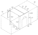
以下、本発明にかかる展示用収容箱を具体化した一実施形態について、図1〜図6を参照して説明する。まず展示用収容箱の構成について図1及び図2を参照して説明する。図1は、本実施の形態における展示用収容箱の斜視構造を示す斜視図であって、図2は、蓋体が取り外された状態の展示用収容箱の斜視構造を示す斜視図である。
(Implementation form)
DESCRIPTION OF EMBODIMENTS Hereinafter, an embodiment embodying an exhibition storage box according to the present invention will be described with reference to FIGS. First, the configuration of the exhibition storage box will be described with reference to FIGS. FIG. 1 is a perspective view showing a perspective structure of an exhibition storage box in the present embodiment, and FIG. 2 is a perspective view showing a perspective structure of the display storage box with a lid removed.
展示用収容箱10は、直方体状に形成された箱体であって、有底の四角筒状に折られた一枚のブランクスから成る身としての収容体11と、該収容体11を覆う有蓋の四角筒状に折られた一枚のブランクスから成る蓋体12とから構成されている。展示用収容箱10の内部に収容された商品等は、収容体11が蓋体12によって覆われた状態で流通された後、蓋体12が収容体11から取り外された状態で展示される。このような構成からなる展示用収容箱10によれば、収容体11から蓋体12が取り外されるだけで展示用のケースが形成されるため、商品等を展示する作業の効率を高めることが可能である。
The
収容体11は、身正面壁11F、身背面壁11B、これら身正面壁11Fと身背面壁11Bとに罫線を介して連結された左右一対の身側面壁11S、及び各壁に罫線を介して連結されたフラップからなる身底面壁11BTを有している。収容体11は、これら身正面壁11F、身背面壁11B、及び左右一対の身側面壁11Sを有する有底四角筒状に折られた一枚のブランクスによって形成されている。なお以下では、一枚のブランクスにおいて罫線で区画された領域をシート片という。
The
商品等とともに展示される収容体11の外形には、それが収容する商品等を購買者に見やすくする機能が必要である。このような要請に基づき、身正面壁11Fにおける高さ方向の幅Ha1が身背面壁11Bにおける高さ方向の幅Hb1よりも小さく、且つ左右一対の身側面壁11Sにおける高さ方向の幅が身正面壁11F寄りになるほど小さくなるように、収容体11の各壁が形成されている。
The outer shape of the
左右一対の身側面壁11Sの各々は、高さ方向の幅が相対的に小さく、且つ身正面壁11Fに連結された正面側部分11SFと、高さ方向の幅が相対的に大きく、且つ身背面壁11Bに連結された背面側部分11SBとを有している。これら一対の身側面壁11Sのうち、右側の身側面壁11Sでは、正面側部分11SFと背面側部分11SBとが共通する一つのシート片で構成されている。これに対して左側の収容体側面壁では、互いに異なる二つのシート片である正面側部分11SFと背面側部分11SBとが高さ方向に沿って接着されている。
Each of the pair of left and right
なお、左側の身側面壁11Sにおける正面側部分11SFは、その身正面壁11F寄りにおいて上記幅Ha1と等しい幅を有する一方、その身背面壁11B寄りでは上記幅Ha1よりも大きい幅を有している。また左側の身側面壁11Sにおける背面側部分11SBは、その身背面壁11B寄りにおいて上記幅Hb1と等しい幅を有する一方、その身正面壁11F寄りでは上記幅Hb1よりも小さい幅を有している。つまり左側の身側面壁11Sにおける正面側部分11SFは、身正面壁11Fと等しい高さ方向の幅Ha1を有して身背面壁11Bに連結された正面側領域と、身背面壁11Bと等しい高さ方向の幅Hb1を有して身背面壁11Bに連結された背面側領域とを有している。さらに左側の身側面壁11Sにおける正面側部分11SFは、これら正面側領域と背面側領域とに挟まれるとともに、背面側領域寄りよりも正面側領域寄りで高さ方向の幅が小さくなる中間領域とを有している。
The front side portion 11SF of the left
身正面壁11Fの上側と身背面壁11Bの上側とには、それぞれ正面切欠部11Faと背面開口部11Baとが形成されている。身正面壁11Fと身背面壁11Bとには、それぞれ正面切欠部11Faの縁に沿ったミシン目線(図3参照)と背面開口部11Baの縁に沿ったミシン目線(図3参照)とが予め設けられ、該ミシン目線によって囲まれた部分が身正面壁11F及び身背面壁11Bから切り取られることによって上記正面切欠部11Faと背面開口部11Baとが形成されている。上記ミシン目線によって囲まれた部分とは、収容体11において蓋体12に接着される箇所であって、蓋体12が収容体11から取り外される際には、蓋体12と共々、収容体11から取り外される箇所である。そして収容体11は、身正面壁11Fの頂縁13Fと正面切欠部11Fa、身側面壁11Sの頂縁13S、身背面壁11Bの頂縁13Bとによって構成される開口11aを有している。なお、高さ方向の幅が身背面壁11Bよりも小さい身正面壁11Fに、さらに上記正面切欠部11Faが形成されるため、このような構成によれば、収容体11が収容する商品等を購買者にさらに見やすくすることが可能である。
A front cut-out portion 11Fa and a back opening 11Ba are formed on the upper side of the
蓋体12は、蓋正面壁12F、蓋背面壁12B、これら蓋正面壁12Fと蓋背面壁12Bとに罫線を介して連結された左右一対の蓋側面壁12S、及び各壁に罫線を介して連結されたフラップからなる蓋頂面壁12Tを有している。蓋体12は、収容体11と相似形の有蓋四角筒状に折られた一枚のブランクスによって形成されている。
The
収容体11の開口11aを覆う蓋体12の外形には、複数の展示用収容箱10が積み重ねられた状態で該展示用収容箱10が歪まないような機械的な強度が必要である。またこの他、商品等が展示される際に不用となる蓋体12の外形には、シートの使用量を少なくするという機能も必要である。このような要請に基づき、蓋正面壁12Fにおける高さ方向の幅Ha2は、身背面壁11Bにおける高さ方向の幅Hb1と略等しく、且つ蓋背面壁12Bにおける高さ方向の幅Hb2よりも大きくなるように設定されて、蓋体12の各壁が形成されている。
The outer shape of the
ここで、上記展示用収容箱10のような直方体状の箱体では、通常、高さ方向に延びる四つの角部の構造が該高さ方向の機械的な強度に大きく影響する。上述した構成によれば、展示用収容箱10が高さ方向において構造的に二つに分割されるとはいえ、高さ方向に延びる四つの角部の各々が高さ方向に延びる一つの側面壁(身背面壁11Bあるいは蓋正面壁12F)によって形成されることになる。それゆえに上記展示用収容箱10では、高さ方向において構造的に連続した直方体状の箱体と比較して、それと同程度の機械的な強度を確保することが可能である。
Here, in a rectangular parallelepiped box such as the
左右一対の蓋側面壁12Sの各々は、高さ方向の幅が相対的に小さく、且つ蓋背面壁12Bに連結された蓋背面側部分12SBと、高さ方向の幅が相対的に大きく、且つ蓋正面壁12Fに連結された蓋正面側部分12SFとを有している。これら一対の蓋側面壁12Sのうち、右側の蓋側面壁12Sでは、蓋正面側部分と蓋背面側部分とが共通する一つのシート片で構成されている。これに対して左側の蓋側面壁12Sでは、互いに異なる二つのシート片である蓋正面側部分12SFと蓋背面側部分12SBとが高さ方向に沿って接着されている。
Each of the pair of left and right lid side walls 12S has a relatively small width in the height direction, a lid back side portion 12SB connected to the lid back
なお、左側の蓋側面壁12Sにおける蓋正面側部分12SFは、その蓋正面壁12F寄りにおいて上記幅Ha2と等しい幅を有する一方、その蓋背面壁12B寄りでは該幅Ha2よりも小さい幅を有している。また左側の蓋側面壁12Sにおける蓋背面側部分12SBは、その蓋背面壁12B寄りにおいて上記幅Hb2と等しい幅を有する一方、その蓋正面壁12F寄りでは該幅Hb2よりも大きい幅を有している。つまり左側の蓋側面壁12Sにおける蓋正面側部分12SFは、蓋正面壁12Fと等しい高さ方向の幅Ha2を有して蓋正面壁12Fに連結された蓋正面側領域と、蓋背面壁12Bと等しい高さ方向の幅Hb2を有して蓋背面壁12Bに連結された蓋背面側領域とを有している。さらに左側の蓋側面壁12Sにおける蓋正面側部分12SFは、これら蓋正面側領域と蓋背面側領域とに挟まれるとともに、蓋背面側領域寄りよりも蓋正面側領域寄りで高さ方向の幅が小さくなる蓋中間領域とを有している。
The lid front side portion 12SF of the left lid side wall 12S has a width equal to the width Ha2 near the
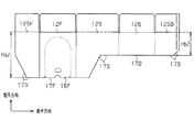
次に、展示用収容箱10の収容体11及び蓋体12について図3及び図4を参照してさらに説明する。図3は、身の展開構造を示す展開図であって、収容体11を形成するためのブランクスの平面構造を示す図である。また図4は、蓋の展開構造を示す展開図であって、蓋体12を形成するためのブランクスの平面構造を示す図である。
Next, the
図3に示されるように、収容体用ブランクスでは、正面側部分11SF、身背面壁11B、身側面壁11S、身正面壁11F、背面側部分11SBが、長手方向に沿って罫線を介して連結されている。また収容体用ブランクスでは、長手方向の一端が正面側部分11SFによって構成されるとともに、長手方向の他端が背面側部分11SBによって構成されている。各正面側部分11SF、身正面壁11F、身側面壁11S、身背面壁11B、背面側部分11SBには、身底面壁11BTを構成するフラップが罫線を介して連結されている。また身正面壁11Fには、頂縁13Fから延びるミシン目線によって囲まれた正面接着部14Fが形成されている。この正面接着部14Fが切り取られることにより上記正面切欠部11Faが形成される。また身背面壁11Bには、頂縁13B側にミシン目線によって囲まれた背面接着部14Bが形成されている。この背面接着部14Bが切り取られることにより、上記背面開口部11Baが形成される。またこの背面接着部14Bには、頂縁13B側に収容用ブランクスの厚みよりも短手方向における開口幅が大きい逃げ孔15が設けられている。この逃げ孔15は、詳しくは後述するが、背面接着部14Bの円滑な切り取りを実現するためのものである。こうした構成からなる収容用ブランクスを罫線に沿って折曲げて適宜接着することにより有底四角筒状の収容体11が形成される。
As shown in FIG. 3, in the case blanks, the front side portion 11SF, the
図4に示されるように、蓋体用ブランクスも同様に、蓋正面側部分12SF、蓋正面壁12F、蓋側面壁12S、蓋背面壁12B、蓋背面側部分12SBが、蓋体用ブランクスの長手方向に沿って罫線を介して連結されている。また蓋体用ブランクスでは、長手方向の一端が蓋正面側部分12SFによって構成されるとともに、長手方向の他端が蓋背面側部分12SBによって構成されている。各蓋正面側部分12SF、蓋正面壁12F、蓋側面壁12S、蓋背面壁12B、蓋背面側部分12SBには、蓋頂面壁12Tを構成するフラップが罫線を介して連結されている。また蓋正面壁12Fの中央には、その底縁17Fから延びるミシン目線によって囲まれた、正面接着部である正面開封部16Fが形成されている。また、図1にも示した高さ方向の幅Hb2は、収容体11における高さ方向の幅Ha1よりも小さく、かつ幅Hb2と幅Ha1との合計が収容体11の身背面壁11Bにおける幅Hb1を超えないように設定される。こうした構成であれば、蓋頂面壁12Tに収容体11の身背面壁11Bの頂縁13Bが当接するように収容体11と蓋体12とを接着させたとしても、蓋背面壁12Bの底縁17Bを身正面壁11Fの頂縁13Fよりも蓋頂面壁12T側に位置させることができる。また、こうした構成であれば、展示用収容箱10を身底面壁11BT側と蓋頂面壁12T側とに二分した場合に、背面接着部14Bを蓋頂面壁12T側に確実に位置させることができる。こうした構成からなる蓋体用ブランクスを罫線に沿って折曲げて適宜接着することにより有蓋四角筒状の蓋体12が形成される。
As shown in FIG. 4, the lid blank similarly includes the lid front side portion 12SF, the
そして、収容体11を蓋体12で覆った状態で、蓋体12における正面開封部16Fの内面と収容体11における正面接着部14Fの外面とが接着され、収容体11における背面接着部14Bを蓋背面壁12Bが覆い隠した状態で該蓋背面壁12Bの外面と該背面接着部14Bの内面とが接着されることにより、展示用収容箱10が形成される。
And in the state which covered the
次に上述した収容体11と蓋体12とで構成される展示用収容箱10の開封作業について説明する。
図5は、展示用収容箱の断面構造を示す断面図であって、開封前の断面構造を示す断面図である。図6は、身背面壁における接着領域付近の断面構造を示す拡大断面図であって、図6(a)は、収容体11の背面接着部14Bの切り取り開始直後、図6(b)は、収容体11の背面接着部14Bが完全に切り取られた状態を示している。
Next, the opening operation | work of the
FIG. 5 is a cross-sectional view showing a cross-sectional structure of the display storage box, and is a cross-sectional view showing the cross-sectional structure before opening. FIG. 6 is an enlarged cross-sectional view showing a cross-sectional structure in the vicinity of the bonding region on the back wall of the body. FIG. 6A is a diagram immediately after the start of cutting of the back surface bonding portion 14B of the
上述した構成の展示用収容箱10は、その開封作業に以下の2つの工程を有している。
工程1:正面開封部16F及び正面接着部14Fの切り取り
工程2:蓋体12の回転操作による蓋体12の取り外し
詳述すると、まず工程1においては、図1に示す状態から、一方の手で展示用収容箱10を押さえた状態で、他方の手を用いて蓋体12の正面開封部16Fをミシン目線に沿って切り取る。これともなって、正面開封部16Fに接着された収容体11の正面接着部14Fがミシン目線に沿って収容体11から切り取られ、これにより正面切欠部11Faが形成される。
The
Step 1: Cutting the
次に、工程2においては、一方の手で収容体11を押さえた状態で、他方の手を用い、蓋頂面壁12Tを収容体11の開口11aから離間させるように蓋背面壁12Bの底縁17Bを軸にして蓋体12を回転させる。ここで、図5に示されるように、蓋体12の回転操作における蓋正面壁12Fの軌跡のうち、最も収容体11に近い位置を辿る軌跡は、蓋背面壁12Bの底縁17Bと蓋正面壁12Fとの距離が最短となる位置の軌跡、すなわち該底縁17Bから蓋正面壁12Fへの垂線である仮想線PLと交差する位置Cの軌跡LCである。つまり蓋体12の回転操作は、これら収容体11及び蓋体12が折り曲げ可能な1枚のブランクスで作製されるとはいえその剛性が高いものとなれば、上記位置Cの軌跡LC上に収容体11の身正面壁11F及び身側面壁11Sが位置していては実現することができない。
Next, in step 2, the bottom edge of the lid
これに対して、上記展示用収容箱10においては、蓋背面壁12Bの幅Hb2を、収容体11の身正面壁11Fにおける幅Ha1よりも小さく、かつ幅Hb2と幅Ha1との合計が収容体11の身背面壁11Bにおける幅Hb1を超えないように設定することで、蓋背面壁12Bの底縁17Bが身正面壁11Fの頂縁13Fよりも蓋頂面壁12T側に位置している。それゆえ、蓋体12の回転操作に対して収容体11の身背面壁11Bが障害になることを回避できる。
On the other hand, in the
また、収容体11の身側面壁11Sは、身正面壁11Fに連結され、該身正面壁11Fの幅Ha1と等しい幅を有する正面側部分11SFと、高さ方向の幅が幅Ha1より大きく、且つ身背面壁11Bに連結された背面側部分11SBとを有している。こうした構成は、収容体11が収容する商品等を購買者に見やすくするためになされてものであるが、同時に、図5からも明らかなように、身側面壁11Sの頂縁13Sを上記位置Cの軌跡LCよりも身底面壁11BT側に位置させている。これは、身側面壁11Sの正面側部分が高さ方向において身正面壁11Fの幅Ha1と等しい幅を有しているとともに、奥行き方向(図5における右方向)において上記位置Cの軌跡LCに対して十分な幅を有しているためである。こうした構成であれば、収容体11の身側面壁11Sの頂縁13Sが上記位置Cの軌跡LCよりも身底面壁11BT側に位置することから、蓋体12の回転操作に対して収容体11の身側面壁11Sが障害になることを回避できる。
The
一方、蓋体12の回転操作によって蓋背面壁12Bは、蓋頂面壁12T側の部位ほど、収容体11の身背面壁11Bから離間する。そのため、図6(a)に示されるように、蓋背面壁12Bに接着された収容体11の背面接着部14Bは、蓋体12の回転操作にともなって、身背面壁11Bの頂縁13Bに近い部分から徐々に切り取られ、やがて図6(b)に示されるように、収容体11から完全に切り取られる。これにより、収容体11には背面開口部11Baが形成される。
On the other hand, the lid
ここで、蓋体12の回転操作にともなって背面接着部14Bを切り取る際に、この背面接着部14Bの軌跡のうち最も蓋背面壁12Bの底縁17Bから遠い位置を辿る軌跡は、身背面壁11Bの頂縁13B側の端部であって身背面壁11B側の角Aの軌跡LAである。この角Aの軌跡LAは蓋体12の回転操作にともなって身背面壁11Bの頂縁13B側に一旦膨らむため、背面接着部14Bがミシン目線で完全に囲まれているとなれば、身背面壁11Bそのものが障害となって背面接着部14Bの円滑な切り取りが実現し難くなる。
Here, when the back surface adhesive portion 14B is cut off in accordance with the rotation operation of the
これに対して、上記構成の展示用収容箱10においては、背面接着部14Bには、頂縁13B側に身背面壁11Bの厚みよりも高さ方向に大きな開口幅を有する逃げ孔15を設けている。こうした逃げ孔15を設けることにより、背面接着部14Bの切り取りに対して身背面壁11Bが障害になることが確実に回避される。これにより、蓋体12の回転操作にともなう背面接着部14Bの切り取りを円滑に実現することが可能である。
On the other hand, in the
また、蓋背面壁12Bには、蓋体12の回転操作によって背面接着部14Bが切り取られるまで、回転軸に作用するモーメントに基づくせん断力が作用する。この際、蓋背面壁12Bの剛性が低いほど、上述したせん断力によって、蓋背面壁12Bが撓みやすくなる。特に、蓋背面壁12Bのうち、背面接着部14Bとの接着部分から蓋頂面壁12Tまでの部位の剛性が低い場合、すなわち背面接着部14Bとの接着部分から蓋頂面壁12Tまでの部位が相対的に長い場合には、そのせん断力によって蓋背面壁12Bが撓みやすくなる。その結果、蓋体12の回転操作によって背面接着部14Bが切り取りにくくなり、ひいては、そのせん断力によって蓋背面壁12Bが折れ曲がってしまうことが懸念される。つまり、開封作業の工程数を減らすことができる一方、蓋背面壁12Bの剛性によっては、折れ曲がった蓋背面壁12Bを回転させるために、過剰な負荷を作業者に強いるという新たな問題を招くおそれがある。
Further, a shearing force based on a moment acting on the rotation axis acts on the lid
これに対して上記構成の展示用収容箱10においては、蓋背面壁12Bの高さ方向の幅Hb2を、身正面壁11Fの高さ方向の幅Ha1よりも小さくした。こうした構成であれば、展示用収容箱10を身底面壁11BT側と蓋頂面壁12T側とに二分した場合に、背面接着部14Bを蓋頂面壁12T側に確実に位置させることができる。これにより、背面接着部14Bが身底面壁11BT側に位置する場合に比べて、蓋背面壁12Bにおける背面接着部14Bとの接着部分から蓋頂面壁12Tまでの部位の剛性が高められることとなる。その結果、蓋背面壁12Bの撓みが抑えられることから、蓋体12の回転操作によって背面接着部14Bを切り取りやすくすることができる。なお、背面接着部14Bは、蓋背面壁12Bを高さ方向に二分した場合に、その一端部が蓋頂面壁12T側に位置していることが好ましい。また、背面接着部14Bが身底面壁11BT側に位置している場合に比べて、蓋体12の回転操作の際に回転軸に作用するモーメントが低減されるため、蓋背面壁12Bに作用するせん断力も低減される。その結果、蓋体12の回転操作による蓋背面壁12Bの撓み、折れ曲がり等が抑えられることから、展示用収容箱10の開封作業の効率が低下してしまうことを抑えることも可能である。
On the other hand, in the
つまり、上述した構成の展示用収容箱10においては、蓋体12の回転操作の際に収容体11の身正面壁11F及び身側面壁11Sが障害となることがないばかりか、収容体11の背面接着部14Bを該収容体11から円滑に切り取ることも可能である。
That is, in the
以上のことから、上記構成の展示用収容箱10においては、開封作業が上記工程1、上記工程2の2つの工程のみで実現可能なため、展示用収容箱10の開封作業の効率を向上させることが可能である。
From the above, in the
以上説明したように、上記実施形態の展示用収容箱10によれば、以下に列挙する効果を得ることができる。
(1)上記実施形態の展示用収容箱10は、正面接着部14Fと正面開封部16F、及び、背面接着部14Bと蓋背面壁12Bで接着されている。また該展示用収容箱10は、身正面壁11Fの頂縁13Fが蓋背面壁12Bの底縁17Bよりも身底面壁11BT側に位置しているとともに、左右一対の身側面壁11Sの各頂縁13Sが位置Cの軌跡LCよりも身底面壁11BT側に位置している。こうした構成によれば、蓋体12の回転操作によって背面接着部14Bの切り取り及び蓋体12の取り外しが同時に行うことが可能であ
ることから、上述した2つの工程だけで展示用収容箱10の開封作業を行うことが可能である。それゆえに展示用収容箱10の開封作業の効率を向上させることができる。
As described above, according to the above you facilities embodiment exhibits
(1) The
(2)背面接着部14Bに逃げ孔15を設けた。こうした構成によれば、蓋体12の回転操作にともなう背面接着部14Bの切り取りを円滑に行うことが可能である。それゆえに、展示用収容箱10の開封作業の効率をさらに向上させることが可能である。
(2) provided with escape holes 15 on the back surface adhesive portion 14B. According to such a configuration, it is possible to smoothly cut out the back surface adhesive portion 14 </ b> B accompanying the rotation operation of the
(3)上記実施形態の展示用収容箱10は、蓋背面壁12Bの高さ方向の幅Hb2は、身正面壁11Fの高さ方向の幅Ha1よりも小さく、かつ幅Hb2と幅Ha1との合計が収容体11の身背面壁11Bにおける幅Hb1を超えないように設定した。
(3) In the
こうした構成であれば、展示用収容箱10を身底面壁11BT側と蓋頂面壁12T側とに二分した場合に、背面接着部14Bを蓋頂面壁12T側に確実に位置させることができる。これにより、蓋体12の回転操作中における蓋背面壁12Bの撓み、折れ曲がり等が抑えられることから、展示用収容箱10の開封作業の効率が低下してしまうことを抑えることが可能である。
With such a configuration, when the
(4)また、蓋頂面壁12Tに収容体11の身背面壁11Bの頂縁13Bが当接するように収容体11と蓋体12とを接着させたとしても、蓋背面壁12Bの底縁17Bを身正面壁11Fの頂縁13Fよりも蓋頂面壁12T側に位置させることができる。
(4) Even if the
(5)上記実施形態の展示用収容箱10は、収容体11の身背面壁11Bにおける高さ方向の幅Hb1と蓋体12の蓋正面壁12Fにおける高さ方向の幅Ha2とを略等しくした。こうした構成であれば、展示用収容箱10の高さ方向における機械的な強度を、高さ方向において構造的に連続した直方体状の箱体と同程度にすることが可能である。
(5) In the
(6)上記実施形態では、背面接着部14Bを収容体11の身背面壁11Bに設けた。こうした構成によれば、開封前の展示用収容箱10においては、背面接着部14Bが蓋背面壁12Bによって覆い隠される。これにより、開封前の展示用収容箱10における背面側の美観性を向上させることが可能である。また、開封後に不用となる背面接着部14Bが、これもまた不用となる蓋体12に接着された状態で切り取られるため、開封後の展示用収容箱10の背面側における美観性が損なわれることもない。
(参考例)
次に、展示用収容箱の参考例について図7及び図8を参照して説明する。
(6) In the above embodiment, the back adhesive portion 14 </ b> B is provided on the
( Reference example )
Next, exhibition reference example of示用containing box will be described with reference to FIGS.
ここで、商品等を展示する展示用収容箱は、例えば、複数の展示用収容箱が箱詰めされた状態で輸送されることが少なくない。そのため、展示用収容箱を箱詰めする際や展示用収容箱をその箱から取り出す際には、複数の展示用収容箱を一度に取り扱うことができる形態が望ましい。参考例の展示用収容箱は、こうした要望に応えるべくなされたものである。なお、参考例の展示用収容箱20は、上記実施形態における展示用収容箱10と主要な構成が同じである。そのため、参考例においては、上記実施形態と異なる部分について詳細に説明し、上記実施形態と同様の部分については同様の符号を付すことによりその詳細な説明は省略する。
Here, the display storage boxes for displaying products and the like are often transported in a state in which a plurality of display storage boxes are packed, for example. For this reason, when packing the exhibition storage box or taking out the display storage box from the box, it is desirable to be able to handle a plurality of display storage boxes at once. The display container for reference is designed to meet these demands. The
図7に示されるように、蓋体12は、有蓋四角筒状に折られた一枚のフランクスによって形成されており、蓋正面壁12F、蓋背面壁12B、これら蓋正面壁12Fと蓋背面壁12Bとに罫線を介して連結された左右一対の蓋側面壁12SL,12SR及び各壁に罫線を介して連結されたフラップからなる蓋頂面壁12Tを有している。
As shown in FIG. 7, the
また、蓋正面壁12Fにおける右側の側縁であって底縁寄りの部位には、蓋正面壁12Fの面方向に沿って蓋側面壁12SRよりもさらに右側方に延びる第1連結フラップ21が連結されている。第1連結フラップ21は、蓋正面壁12Fの側縁に沿って形成されたミシン目線22を介して蓋正面壁12Fに連結されており、このミシン目線22に沿って蓋正面壁12Fから切り離し可能になっている。
Further, a
また、蓋背面壁12Bにおける左側の側縁であって頂縁寄りの部位には、蓋背面壁12Bの面方向に沿って蓋側面壁12SLよりもさらに左側方に延びる第2連結フラップ26が連結されている。第2連結フラップ26は、蓋背面壁12Bの側縁に沿って形成されたミシン目線27を介して蓋背面壁12Bに連結されており、このミシン目線27に沿って蓋背面壁12Bから切り離し可能になっている。
Further, a second connecting
そして、蓋側面壁12SR,12SLが互いに当接するように複数の展示用収容箱20を並べるときには、展示用収容箱20の第1連結フラップ21は、右側に隣接する展示用収容箱20の蓋正面壁12Fに対向するように配置され、該蓋正面壁12Fに接着することが可能となる。また、第2連結フラップ26は、左側に隣接する展示用収容箱20の蓋背面壁12Bに対向するように配置され、該蓋背面壁12Bに接着することが可能となる。
When the plurality of
次に、展示用収容箱20の蓋体12について図8を参照してさらに説明する。図8に示されるように、蓋体用ブランクスでは、蓋側面壁12SL、蓋正面壁12F、蓋側面壁12SR、蓋背面壁12Bが長手方向に沿って罫線を介して連結されている。蓋側面壁12SL、蓋正面壁12F、蓋側面壁12SR、蓋背面壁12Bの各々には、その短手方向に、蓋体12の蓋頂面壁12Tを構成するフラップが罫線を介して連結されている。蓋体12は、蓋体用ブランクスを罫線に沿って折り曲げて適宜接着することにより有蓋四角筒状の蓋体12が形成される。
Next, the
また、蓋正面壁12Fにおける蓋側面壁12SR側の側縁であって底縁17F寄りの部位には、ミシン目線22を介して第1連結フラップ21が連結されている。第1連結フラップ21は、ブランクスの状態では蓋側面壁12SRのシート片の一部であって、該シート片において切れ目線23によって画定されている。この切れ目線23に沿った部位は、ミシン目線22に沿った部位よりも切り離しが容易な部位である。そして、第1連結フラップ21は、ブランクスを折り曲げて蓋体12を形成する際に、蓋正面壁12Fに対して蓋側面壁12SRのみが罫線に沿って折り曲げられることで、切れ目線23に沿って蓋側面壁12SRから切り離される。
Further, the first connecting
また、蓋背面壁12Bの側縁であって底縁17B寄りの部位には、該蓋背面壁12Bを蓋側面壁12SLに接着するための接着フラップ25が罫線を介して連結されている。一方、蓋背面壁12Bの側縁であって頂縁寄りの部位には、第2連結フラップ26がミシン目線27を介して連結されている。これら接着フラップ25と第2連結フラップ26は、一体形成されたフラップであって、切れ目線28によってそれぞれが画定されている。この切れ目線28に沿った部位は、ミシン目線27に沿った部位よりも切り離しが容易な部位である。そして、第2連結フラップ26は、ブランクスを折り曲げて蓋体12を形成する際に、蓋背面壁12Bに対して接着フラップ25のみが罫線に沿って折り曲げられることで、切れ目線28に沿って接着フラップ25から切り離される。
Further, an
この接着フラップ25は、蓋正面壁12Fに対して蓋側面壁12SL,12SRがともに折り曲げられ、且つ蓋側面壁12SRに対して蓋背面壁12Bが折り曲げられた状態で蓋側面壁12SLの内面に接着される。そして接着フラップ25が蓋側面壁12SLに接着された状態で、各壁に設けられ蓋体12の蓋頂面壁12Tを構成するフラップが互いに重なるように折り畳まれて、適宜粘着テープ等で接着されることにより蓋体12が形成される。
The
なお、展示用収容箱20の連結を解除する際には、ミシン目線22に沿って第1連結フラップ21を蓋正面壁12Fから切り離すとともに、ミシン目線27に沿って第2連結フラップ26を蓋背面壁12Bから切り離す。これにより、隣接する展示用収容箱20との連結が解除される。
When the connection of the
また、参考例の展示用収容箱20は、蓋体12の幅Hb2が収容体11の幅Ha1よりも大きく、具体的には幅Ha1が90.5mm、幅Hb1が142mm、幅Ha2が143mm、幅Hb2が123mmである。そして、蓋頂面壁12Tに収容体11の身背面壁11Bの頂縁13Bが当接するように収容体11に蓋体12が接着される。こうした構成のもとでは、蓋体12の蓋背面壁12Bの底縁17Bが収容体11の身正面壁11Fの頂縁13Fよりも身底面壁11BT側に位置してしまう。しかしながら、こうした場合には、剛性の低い紙で展示用収容箱20を作製することによって、蓋体12の回転操作を操作しにくくはなるものの、蓋体12の回転操作による蓋体12の取り外しが可能である。
The
以上説明したように、上記参考例の展示用収容箱20によれば、上記(1)(2)(5)(6)に記載した効果に加えて、以下に列挙する効果を得ることができる。
(7)参考例では、蓋正面壁12Fに第1連結フラップ21、蓋背面壁12Bに第2連結フラップ26を設けた。こうした構成によれば、展示用収容箱20と、当該展示用収容箱20の右側で隣接する展示用収容箱20との蓋体12同士を第1連結フラップ21で連結することが可能である。また、展示用収容箱20と、当該展示用収容箱20の左側で隣接する展示用収容箱20との蓋体12同士を第2連結フラップ26で連結することが可能である。すなわち、複数の展示用収容箱20を連結することが可能である。
As described above, according to the
(7) In the reference example , the
(8)また、第1及び第2連結フラップ21,26がともにミシン目線22,27を介して設けられている。そのため、ミシン目線22に沿って第1連結フラップ21を蓋正面壁12Fから切り離すとともに、ミシン目線27に沿って第2連結フラップ26を蓋背面壁12Bから切り離すことによって、連結状態にある展示用収容箱20を容易に切り離すことも可能である。
(8) Moreover, the 1st and 2nd connection flaps 21 and 26 are provided through the perforation lines 22 and 27, respectively. Therefore, the
(9)そのうえ、上記第1及び第2連結フラップ21,26が蓋体12に設けられていることから、切り離し後の第1及び第2連結フラップ21,26は、隣接する展示用収容箱20の蓋体12、すなわち開封後に不用となる蓋体12に接着された状態となる。その結果、開封後における展示用収容箱20の美観性が損なわれることもない。
(9) Moreover, since the first and second connection flaps 21 and 26 are provided on the
(10)参考例では、蓋体12を形成するための帯状のブランクスのうち、該ブランクスの長手方向の一部が、蓋正面壁12Fとして利用される。そして、蓋正面壁12Fの側縁に連結される部分が、該ブランクスの短手方向において、第1連結フラップ21と蓋側面壁12SRとに二分される。そのため、蓋正面壁12Fの側縁に連結される部分が、第1連結フラップ21として有効的に利用されることとなる。そして、蓋正面壁12Fの側縁に連結される部分の全てが蓋側面壁12SRとして利用される場合と比較して、ブランクスの紙量が増えることもないし、ブランクスの取扱性、蓋体12の組立性や生産性が低下することも極力抑えることができる。
(10) In the reference example , among the strip-shaped blanks for forming the
また、第1連結フラップ21を不用とする要求に対しては、蓋正面壁12Fに対して、蓋側面壁12SR共々、第1連結フラップ21を折り曲げることによって、第1連結フラップ21を蓋側面壁12SRの一部として用いることができる。
Further, in response to a request that the
(11)また、蓋側面壁12SRのシート片において第1連結フラップ21が切れ目線23で画定されている。そのため、第1連結フラップ21を蓋側面壁12SRの一部として用いた場合であっても、切れ目線23に沿って第1連結フラップ21を蓋側面壁12SRから切り離すことで、第1連結フラップ21を容易に出現させることができる。
(11) Moreover, the
(12)参考例では、蓋体12を形成するための帯状のブランクスのうち、該ブランクスの長手方向の一部が、蓋背面壁12Bとして利用される。そして、蓋背面壁12Bの側縁に連結される部分が、該ブランクスの短手方向において、接着フラップ25と第2連結フラップ26とに二分される。そのため、蓋背面壁12Bの側縁に連結される部分が、第2連結フラップ26として有効的に利用されることとなる。そして、蓋背面壁12Bの側縁に連結される部分の全てが接着フラップ25として利用される場合と比較して、ブランクスの紙量が増えることもないし、ブランクスの取扱性、蓋体12の組立性や生産性が低下することを極力抑えることもできる。
(12) In the reference example , among the strip-shaped blanks for forming the
(13)参考例では、第2連結フラップ26は、接着フラップ25から切れ目線28で切り離されることによって形成され、その接着フラップ25が蓋側面壁12SLの内面に接着されることによって蓋体12が環状に形成される。そのため、第2連結フラップ26を不用とする要求に対しては、接着フラップ25共々、第2連結フラップ26を蓋側面壁12SLの内側に配置することもできる。
(13) In the reference example , the second connecting
なお、上記実施形態は以下のように変更してもよい。
・上記実施形態では、背面接着部14Bを収容体11の身背面壁11Bに設けた。これを変更して、背面接着部を蓋体12の蓋背面壁12Bに設けてもよい。こうした構成であっても、上記(1)〜(5)と同様の効果を得ることが可能である。
In addition, you may change the said embodiment as follows.
In the above embodiment, the back adhesive portion 14 </ b> B is provided on the
・上記実施形態では、収容体11の身正面壁11Fにおける高さ方向の幅Ha1と蓋体12の蓋背面壁12Bにおける高さ方向の幅Hb2との合計が、収容体11の身背面壁11Bの高さ方向における幅Hb1よりも小さくなるように設定した。これを変更して、幅Ha1と幅Hb2との合計が幅Hb1と略等しくてもよい。こうした構成であっても、上記(1)〜(5)と同様の効果を得ることが可能であるとともに、収容体ブランクス及び蓋体用ブランクスの成型に関し、歩留まりの向上が見込まれる。また、幅Ha1と幅Hb2との合計が幅Hb1より大きくてもよい。こうした場合であっても(1)〜(3)と同様の効果を得ることが可能である。しかしながら、収容体11の身正面壁11Fの頂縁13Fを蓋体12の蓋背面壁12Bの底縁17Bよりも身底面壁11BT側に位置させるうえでは、収容体11の身背面壁11Bを蓋頂面壁12Tに当接させた状態で収容体11と蓋体12とを接着することが困難になる。そのため、展示用収容箱10の高さ方向における機械的な強度の低下が懸念される。
· In the above you facilities embodiment, the sum of the height direction of the width Hb2 in the lid
・上記実施形態では、蓋背面壁12Bにおける高さ方向の幅Hb2は、身正面壁11F
の高さ方向の幅Ha1よりも小さくした。これを変更して、幅Hb2と幅Ha1とを略等しくしてもよい。こうした構成であっても、上記(1)〜(3)と同様の効果を得ることが可能であるとともに、収容体ブランクス及び蓋体用ブランクスの成型に関し、歩留まりの向上が見込まれる。
· In the above you facilities embodiment, the width Hb2 in the height direction of the lid
It was made smaller than the width Ha1 in the height direction. By changing this, the width Hb2 and the width Ha1 may be substantially equal. Even if it is such a structure, while being able to acquire the effect similar to said (1)-(3), the improvement of a yield is anticipated regarding shaping | molding of the container blanks and the blanks for lids.
・また、参考例のように、蓋背面壁12Bにおける高さ方向の幅Hb2を、身正面壁11Fの高さ方向の幅Ha1より大きくしてもよい。こうした構成であっても上記(1)(2)と同様の効果を得ることが可能である。しかしながらこの場合も、収容体11の身正面壁11Fの頂縁13Fを蓋体12の蓋背面壁12Bの底縁17Bよりも身底面壁11BT側に位置させるうえでは、収容体11の身背面壁11Bを蓋頂面壁12Tに当接させた状態で収容体11と蓋体12とを接着することが困難になる場合ある。そのため、展示用収容箱10の高さ方向における機械的な強度の低下が懸念される。
In addition, as in the reference example , the width Hb2 in the height direction of the lid back
・上記実施形態では、背面接着部14Bには、頂縁13B側に収容用ブランクスの厚みよりも短手方向における開口幅が大きい逃げ孔15が設けた。これを変更して、背面接着部14Bから逃げ孔15を割愛してもよい。こうした構成であっても、上記(1)と同様の効果を得ることが可能である。
In the above embodiment, the back adhesive portion 14B is provided with the
A…角、C…位置、LA,LC…軌跡、PL…仮想線、Wa…正面壁、Wb…背面壁、Ha1,Ha2,Hb1,Hb2…幅、10,20…展示用収容箱、11…収容体、11a…開口、11B…身背面壁、11F…身正面壁、11S…身側面壁、11Ba…背面開口部、11BT…身底面壁、11Fa…正面切欠部、11SB…背面側部分、11SF…正面側部分、12…蓋体、12B…蓋背面壁、12F…蓋正面壁、12S,12SL,12SR…蓋側面壁、12T…蓋頂面壁、12SB…蓋背面側部分、12SF…蓋正面側部分、13B,13F,13S…頂縁、14B…背面接着部、14F…正面接着部、15…逃げ孔、16F…正面開封部、17B,17F…底縁、21…第1連結フラップ、22…ミシン目線、23…切れ目線、25…接着フラップ、26…第2連結フラップ、27…ミシン目線、28…切れ目線、50…展示用収容箱、51…収容体、52…蓋体、51A,52A…ブランクス、53,54,55,56…接着領域。 A ... Corner, C ... Position, LA, LC ... Trajectory, PL ... Virtual line, Wa ... Front wall, Wb ... Back wall, Ha1, Ha2, Hb1, Hb2 ... Width, 10, 20 ... Exhibition container, 11 ... Housing, 11a ... Opening, 11B ... Body back wall, 11F ... Body front wall, 11S ... Body side wall, 11Ba ... Back opening, 11BT ... Body bottom wall, 11Fa ... Front notch, 11SB ... Back side part, 11SF ... Front side part, 12 ... Lid, 12B ... Lid rear wall, 12F ... Lid front wall, 12S, 12SL, 12SR ... Lid side wall, 12T ... Lid top wall, 12SB ... Lid rear side part, 12SF ... Lid front side Part, 13B, 13F, 13S ... Top edge, 14B ... Back adhesive part, 14F ... Front adhesive part, 15 ... Escape hole, 16F ... Front opening part, 17B, 17F ... Bottom edge, 21 ... First connecting flap, 22 ... Perforation line, 23 ... cut line, 5 ... Adhesive flap, 26 ... Second connecting flap, 27 ... Perforation line, 28 ... Cut line, 50 ... Display box, 51 ... Container, 52 ... Lid, 51A, 52A ... Blanks, 53, 54, 55 56 ... Adhesion area.
Claims (5)
前記身は、身正面壁、身背面壁、左右一対の身側面壁、及び身底面壁で構成され、
前記蓋は、蓋正面壁、蓋背面壁、左右一対の蓋側面壁、及び蓋頂面壁で構成され、
前記身の正面側の高さは、前記身の背面側の高さよりも小さく、
前記蓋背面壁の底縁は、前記身背面壁の底縁よりも高く配置され、
前記蓋背面壁の底縁を中心にして前記身正面壁上及び前記身側面壁上を前記蓋正面壁が回転することによって前記蓋が前記身から取り外される展示用収容箱であって、
前記身正面壁の外面と前記蓋正面壁の内面とが互いに接着され、
前記身背面壁の外面と前記蓋背面壁の内面とが互いに接着され、
前記身正面壁及び前記蓋正面壁は、
互いに対向する領域にミシン目線で囲まれた正面接着部を有し、
前記身背面壁及び前記蓋背面壁の一方は、
互いに対向する領域にミシン目線で囲まれた背面接着部を有する
ことを特徴とする展示用収容箱。 A bottomed rectangular tube-shaped body, and a covered square tube-shaped lid that covers the body from the outside,
The body is composed of a front wall, a back wall, a pair of left and right side walls, and a bottom wall,
The lid is composed of a lid front wall, a lid rear wall, a pair of left and right lid side walls, and a lid top wall.
The height of the front side of the body is smaller than the height of the back side of the body,
The bottom edge of the lid back wall is disposed higher than the bottom edge of the back wall,
An exhibition storage box in which the lid is removed from the body by rotating the lid front wall on the body front wall and the body side wall around the bottom edge of the lid back wall,
The outer surface of the body front wall and the inner surface of the lid front wall are bonded together,
The outer surface of the back wall and the inner surface of the lid back wall are bonded together,
The body front wall and the lid front wall are:
It has a front adhesive part surrounded by perforations in areas facing each other,
One of the body back wall and the lid back wall is
An exhibition storage box having a back adhesive portion surrounded by a perforation line in regions facing each other.
ことを特徴とする請求項1に記載の展示用収容箱。 2. The display according to claim 1, wherein a hole having an opening width in a height direction equal to or larger than a thickness of the back surface adhesive portion is formed at an end of the back surface adhesive portion on the lid top wall side. Storage box.
ことを特徴とする請求項1〜3のいずれか一項に記載の展示用収容箱。 The sum of the width in the height direction of the body front wall and the width in the height direction of the lid back wall is equal to or less than the width in the height direction of the body back wall. The display storage box according to any one of the above.
ことを特徴とする請求項1〜4のいずれか一項に記載の展示用収容箱。 The exhibition storage box according to any one of claims 1 to 4, wherein the back adhesive portion is provided on the back wall of the body.
Priority Applications (1)
| Application Number | Priority Date | Filing Date | Title |
|---|---|---|---|
| JP2011147679A JP5524911B2 (en) | 2010-07-02 | 2011-07-01 | Storage box for exhibition |
Applications Claiming Priority (3)
| Application Number | Priority Date | Filing Date | Title |
|---|---|---|---|
| JP2010152402 | 2010-07-02 | ||
| JP2010152402 | 2010-07-02 | ||
| JP2011147679A JP5524911B2 (en) | 2010-07-02 | 2011-07-01 | Storage box for exhibition |
Related Child Applications (1)
| Application Number | Title | Priority Date | Filing Date |
|---|---|---|---|
| JP2011288791A Division JP5779088B2 (en) | 2010-07-02 | 2011-12-28 | Storage box for exhibition |
Publications (3)
| Publication Number | Publication Date |
|---|---|
| JP2012030892A JP2012030892A (en) | 2012-02-16 |
| JP2012030892A5 JP2012030892A5 (en) | 2012-03-29 |
| JP5524911B2 true JP5524911B2 (en) | 2014-06-18 |
Family
ID=45844811
Family Applications (2)
| Application Number | Title | Priority Date | Filing Date |
|---|---|---|---|
| JP2011147679A Active JP5524911B2 (en) | 2010-07-02 | 2011-07-01 | Storage box for exhibition |
| JP2011288791A Active JP5779088B2 (en) | 2010-07-02 | 2011-12-28 | Storage box for exhibition |
Family Applications After (1)
| Application Number | Title | Priority Date | Filing Date |
|---|---|---|---|
| JP2011288791A Active JP5779088B2 (en) | 2010-07-02 | 2011-12-28 | Storage box for exhibition |
Country Status (1)
| Country | Link |
|---|---|
| JP (2) | JP5524911B2 (en) |
Families Citing this family (5)
| Publication number | Priority date | Publication date | Assignee | Title |
|---|---|---|---|---|
| JP5990396B2 (en) * | 2012-04-23 | 2016-09-14 | キユーピー株式会社 | Packaging box and method for detecting mischief of packaging box |
| JP5782470B2 (en) * | 2013-02-18 | 2015-09-24 | 株式会社クラウン・パッケージ | Packaging box |
| WO2015060073A1 (en) | 2013-10-24 | 2015-04-30 | レンゴー株式会社 | Box for packaging and exhibition, and packaging device for same |
| CN105813946B (en) | 2013-10-24 | 2017-10-03 | 联合株式会社 | Presentation dual-purpose case and its packing device |
| JP2016120967A (en) * | 2014-03-28 | 2016-07-07 | レンゴー株式会社 | Packaging and displaying box and packaging device |
Family Cites Families (5)
| Publication number | Priority date | Publication date | Assignee | Title |
|---|---|---|---|---|
| JPS6269417U (en) * | 1985-10-23 | 1987-05-01 | ||
| JPH08253229A (en) * | 1995-03-15 | 1996-10-01 | Asahi Insatsu Shiki Kk | Packaging case with shaking-out opening |
| JP2003128052A (en) * | 2001-10-23 | 2003-05-08 | Sony Corp | Packing case |
| GB0911014D0 (en) * | 2009-06-25 | 2009-08-12 | Ds Smith Packaging Ltd | Blanks for packaging cartons |
| JP5550987B2 (en) * | 2010-05-24 | 2014-07-16 | 日本トーカンパッケージ株式会社 | Display container and method for manufacturing display container |
-
2011
- 2011-07-01 JP JP2011147679A patent/JP5524911B2/en active Active
- 2011-12-28 JP JP2011288791A patent/JP5779088B2/en active Active
Also Published As
| Publication number | Publication date |
|---|---|
| JP2012062123A (en) | 2012-03-29 |
| JP2012030892A (en) | 2012-02-16 |
| JP5779088B2 (en) | 2015-09-16 |
Similar Documents
| Publication | Publication Date | Title |
|---|---|---|
| US11794948B2 (en) | Shelf-ready shipper display system | |
| JP5524911B2 (en) | Storage box for exhibition | |
| US9783334B2 (en) | Shipping and display container | |
| US20060060643A1 (en) | Display containers with removable panel | |
| US20220073263A1 (en) | Plastic Wrap Container | |
| US20120061457A1 (en) | Carton With Angled Corner Panels | |
| US20100282831A1 (en) | Retail ready display tray | |
| JP2012030892A5 (en) | ||
| JP5550987B2 (en) | Display container and method for manufacturing display container | |
| JP2009067449A (en) | Packaging box | |
| WO2012119198A1 (en) | Shelf-ready packaging | |
| JP5377952B2 (en) | Packaging box | |
| JP5330834B2 (en) | Improvement of hinge lid container and blank | |
| JP3224573U (en) | Packaging box | |
| CA2745166C (en) | Shelf-ready shipper display system | |
| JP6328163B2 (en) | Packaging container | |
| JP7409989B2 (en) | packaging box | |
| KR20220015408A (en) | Boxes with major flap overlaps | |
| JP6595367B2 (en) | Packaging box | |
| JP7404188B2 (en) | packaging box | |
| JP3216301U (en) | Packaging box | |
| JP2011098763A (en) | Packaging box | |
| JP7102291B2 (en) | Packaging container | |
| JP7218248B2 (en) | packaging box | |
| JP7187978B2 (en) | packaging box |
Legal Events
| Date | Code | Title | Description |
|---|---|---|---|
| A521 | Request for written amendment filed |
Free format text: JAPANESE INTERMEDIATE CODE: A523 Effective date: 20111228 |
|
| A621 | Written request for application examination |
Free format text: JAPANESE INTERMEDIATE CODE: A621 Effective date: 20130724 |
|
| A621 | Written request for application examination |
Free format text: JAPANESE INTERMEDIATE CODE: A621 Effective date: 20130724 |
|
| A977 | Report on retrieval |
Free format text: JAPANESE INTERMEDIATE CODE: A971007 Effective date: 20140314 |
|
| TRDD | Decision of grant or rejection written | ||
| A01 | Written decision to grant a patent or to grant a registration (utility model) |
Free format text: JAPANESE INTERMEDIATE CODE: A01 Effective date: 20140401 |
|
| A61 | First payment of annual fees (during grant procedure) |
Free format text: JAPANESE INTERMEDIATE CODE: A61 Effective date: 20140410 |
|
| R150 | Certificate of patent or registration of utility model |
Ref document number: 5524911 Country of ref document: JP Free format text: JAPANESE INTERMEDIATE CODE: R150 |
|
| R250 | Receipt of annual fees |
Free format text: JAPANESE INTERMEDIATE CODE: R250 |
|
| R250 | Receipt of annual fees |
Free format text: JAPANESE INTERMEDIATE CODE: R250 |
|
| R250 | Receipt of annual fees |
Free format text: JAPANESE INTERMEDIATE CODE: R250 |
|
| R250 | Receipt of annual fees |
Free format text: JAPANESE INTERMEDIATE CODE: R250 |
|
| R250 | Receipt of annual fees |
Free format text: JAPANESE INTERMEDIATE CODE: R250 |
|
| R250 | Receipt of annual fees |
Free format text: JAPANESE INTERMEDIATE CODE: R250 |
|
| R250 | Receipt of annual fees |
Free format text: JAPANESE INTERMEDIATE CODE: R250 |
|
| R250 | Receipt of annual fees |
Free format text: JAPANESE INTERMEDIATE CODE: R250 |