JP5377952B2 - Packaging box - Google Patents
Packaging box Download PDFInfo
- Publication number
- JP5377952B2 JP5377952B2 JP2008326096A JP2008326096A JP5377952B2 JP 5377952 B2 JP5377952 B2 JP 5377952B2 JP 2008326096 A JP2008326096 A JP 2008326096A JP 2008326096 A JP2008326096 A JP 2008326096A JP 5377952 B2 JP5377952 B2 JP 5377952B2
- Authority
- JP
- Japan
- Prior art keywords
- plate
- plates
- bottom plate
- reinforcing
- folding
- Prior art date
- Legal status (The legal status is an assumption and is not a legal conclusion. Google has not performed a legal analysis and makes no representation as to the accuracy of the status listed.)
- Expired - Fee Related
Links
Images


Landscapes
- Cartons (AREA)
Abstract
Description
本発明は包装箱に関する。 The present invention relates to a packaging box.
ダンボール等の厚紙素材からなる包装箱として、特許文献1に記載の如く、方形の底板1の相対する辺に夫々側板2と、該一方の側板2に蓋板3と、更に該蓋板3に接合板4とを夫々折線を介して連設し、底板1と蓋板3の各両側に夫々前記側板2に対し半幅以下の狭幅の側板5を折線を介して連設すると共に、広幅の両側板2には3条の平行な折線を介して適当幅の袖板6Aと補強板6Bと接着板6Cとを連設し、底板1に対し両側の広幅側板2を垂直に起立させると共にその各両側の袖板6Aと補強板6Bを内方に屈折して接着板6Cを広幅側板2の内面に接着することにより両広幅側板2の両縁に沿って柱状の補強部6を形成し、蓋板3を起立した両広幅側板2の上面に亘り折曲げて接合板4を一方の広幅側板2の外面に接着し、又底板1と蓋板3の狭幅側板5を両側の袖板6Aの外面に接着してなるものである(図9)。
As a packaging box made of a cardboard material such as cardboard, as described in
特許文献1に記載の包装箱によれば、1枚の厚紙素材から組立成形される蓋付き箱体の各コーナーに柱状の補強部6を形成でき、積重ね強度を向上できる。
しかしながら、特許文献1に記載の包装箱では、底板1に対する一側辺に1枚の側板2を連設し、底板1に対するその反対の側辺に1枚の側板2及び蓋板3を連設するものであり、図9に示すように、底板1、側板2、蓋板3と連設する方向において展開形状が非対称をなし、製函機等による製函性が悪い。
However, in the packaging box described in
特に、柱状の補強部6を形成する袖板6Aと補強板6Bと接着板6Cが、底板1と蓋板3に連設されているそれぞれの狭幅側板5に挟まれるから、この柱状の補強部6を形成する工程で、袖板6Aを直角に内方に屈折し更にこれに続く補強板6Bを内方に折曲げて更にこれに続く接着板6Cを広幅側板2の内面に接着することにより該側板2の両側縁に沿う断面3角形状の空間を有する補強部6を折曲げ接着する煩雑な作業を、底板1に連設されている狭幅側板5と蓋板3に連設されている狭幅側板5に両側から挟まれる狭小スペースで行なうものになり、製函性は極めて悪い。
In particular, since the
本発明の課題は、1枚の圧紙素材から組立成形されて補強柱を備える蓋付き包装箱において、製函性を向上することにある。 An object of the present invention is to improve box-making performance in a packaging box with a lid which is assembled and formed from a single sheet of pressure paper material and has reinforcing columns.
請求項1の発明は、方形の底板の相対する一対の辺のそれぞれに折線を介して同一高さをなす正面板と背面板を連設し、正面板と背面板のそれぞれにおける底板に対する反対側の辺に折線を介して蓋板を連設し、底板の両側にそれぞれ前記正面板及び背面板と同一高さの側板を折線を介して連設し、各側板における底板に対する反対側の辺に折線を介して接合フラップを連設し、各側板の両縁に折線を介して複数条の折曲フラップからなる補強板を連設し、両側の側板の各両縁の補強板の折曲フラップを折曲げて先端側の折曲フラップを側板の内面に接着することにより側板の両縁に沿う補強柱を形成するとともに、底板に対し両側の側板を起立させ、正面板と背面板を底板に対し起立させて両側板の各両縁に沿う補強柱の外面に接着し、正面板と背面板に対し各蓋板を折曲げ、各蓋板を補強柱の上端の側に折込まれる各接合フラップの上面に接着してなる包装箱であって、前記正面板と背面板のそれぞれに、底板側の折線と蓋板側の折線に挟まれる高さ方向中間部に位置して各折れ線と平行をなす切断誘導部を設け、前記各蓋板が接着された各接合フラップの各側板との連設部に切断誘導部を設け、前記正面板及び背面板の高さ方向中間部の切断誘導部を切除するとともに、前記両蓋板が接着されている各接合フラップの各側板との連設部に設けた切断誘導部を切除することにより、正面板の上部の部分、両蓋板及び接合フラップの接合体の部分、並びに背面板の上部の部分を開封して除去可能にするようにしたものである。 According to the first aspect of the present invention, a front plate and a back plate having the same height are connected to each of a pair of opposite sides of a square bottom plate via a fold line, and the front plate and the back plate are opposite to the bottom plate. A side plate having the same height as that of the front plate and the back plate is provided on both sides of the bottom plate via a broken line, and on each side plate on the opposite side to the bottom plate. Joining flaps are continuously connected via folding lines, and reinforcing plates made up of a plurality of folding flaps are connected to both edges of each side plate via folding lines, and the folding flaps of the reinforcing plates on both sides of both side plates are connected. The side plate on both sides is raised from the bottom plate, and the front plate and the back plate are used as the bottom plate. Adhere to the outer surface of the reinforcing column along both edges of both side plates. Folding each cover plate to the plate and the back plate, a packing box made by bonding to the upper surface of the bonding flaps folded each cover plate on the side of the upper end of the reinforcing pillars, the rear plate and the front plate Each is provided with a cutting guide portion parallel to each fold line located in the height direction intermediate part sandwiched between the fold line on the bottom plate side and the fold line on the cover plate side, and each of the joining flaps to which the respective cover plates are bonded A cutting guide portion is provided in a continuous portion with the side plate, the cutting guide portion in the intermediate portion in the height direction of the front plate and the back plate is excised, and each side plate of each joining flap to which the both cover plates are bonded, By cutting off the cutting guide portion provided in the continuous portion, the upper portion of the front plate, the lid plate and the joined flap portion, and the upper portion of the back plate can be opened and removed. It is what I did.
図1に示した包装箱10は、一枚のダンボール(他の板紙等の厚紙でも可)を素材として組立成形されるものであり、特にパウチ等、製品自身で強度を持たない物品を収容することができる。また、包装箱10を複数個上下に段積みされて保管され、又は図2に示す如くに開封されて陳列に供される。
The
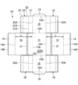
包装箱10は、ダンボール原紙から抜き型により打ち抜かれた図3に示す如くの板紙の展開素材から製作される。包装箱10の板紙は、方形の底板11の相対する一対の辺のそれぞれに折線12A、13Aを介して同一高さ(h)をなす正面板12と背面板13を連設し、正面板12と背面板13のそれぞれにおける底板11に対する反対側の辺に折線14A、14Aを介して蓋板14、14を連設する。本実施例では、各蓋板14の折線14Aから反対側の辺14Bまでの長さを底板11の概ね半幅とした。
The
包装箱10は、底板11の前記正面板及び背面板に連設する辺とは異なる他の一対の辺のそれぞれに正面板12及び背面板13と同一高さの側板15、15を折線15A、15Aを介して連設し、各側板15における底板11に対する反対側の辺に折線16A、16Aを介して接合フラップ16、16を連設し、各側板15の前後の両縁に折線20Aを介して補強板20を連設する。補強板20は、複数条(本実施例では3条)をなす適宜幅の折曲フラップ21、22、23を順に連設してなり、折曲フラップ21と折曲フラップ22を折曲線22Aを介して連設し、折曲フラップ22と折曲フラップ23を折曲線23Aを介して連設する。補強板20は、後述する補強柱24(図1(B)の丸で囲った部分)を形成する。
The
また、包装箱10は、正面板12と背面板13のそれぞれに、高さ(h)の間に直交する方向で、底板側の折線(12A,13A)もしくは蓋板側の折線(14A,14A)に平行な開封用の切断誘導部31、31を設け、各接合フラップ16の各側板15との連設部(接合フラップ16の側)に開封用の切断誘導部32(図1の(A)の斜線部で示す)を設けている。包装箱10は、切断誘導部32により正面板12及び背面板13の各上部12U、13U並びに各蓋板14を切除し開封される(図2(A)の蓋体)とともに、正面板12及び背面板13の各下部12L、13Lを袖壁として残す(図2(B)の蓋体)。切断誘導部31は例えばジッパー又はテアテープからなる。切断誘導部32は例えばジッパー又はミシン目からなる。
Further, the
更に、包装箱10は、ダンボール原紙又はダンボール素材の段階で、例えば図4に斜線で示す範囲、即ち、包装箱を組み立てた際に表面に現れる部分全域に印刷柄を付与することができる。印刷柄を付された正面板12及び背面板13の各上部12U、13U並びに各蓋板14は開封時に箱体から切除される。印刷柄を付された正面板12及び背面板13の各下部12L、13L並びに各側板15が開封後も箱体に残る。従って、デザイン上の制約が少なくなり、印刷効率が良い。
Further, the
包装箱10は、以上のダンボール素材により以下の工程で組立てられて箱体を成形する(図5、図6)。
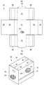
(1)包装箱10の展開素材(図5(A))の両側の側板15、15の各両縁の補強板20の折曲フラップ21、22、23を折曲げて先端側の折曲フラップ23を側板15の内面に接着する(図5(B)、図5(B)の斜線部が糊付部を示す)。本実施例では、各側板15の縁における折曲フラップ21を直角に内方に折曲げ、更に折曲フラップ22を内方に折曲げ、更に折曲フラップ23を側板15の内面に接着する。これにより、各側板15の両縁に沿う補強柱24が形成される。補強柱24の下端は底板11の上面に載り、補強柱24の全高さは正面板12及び背面板13並びに側板15の全高さに一致するものになる。尚、直角に折り曲げられた折曲げフラップ21の外側の面のそれぞれは、正面板12及び背面板13を起立させ時に接着される(図6(B)の斜線部)。
The
(1) The folding flaps 21, 22, and 23 of the reinforcing
(2)底板11に対し両側の側板15を補強柱24とともに起立させる(図6(A))。
(2) The
(3)正面板12と背面板13を底板11に対し起立させて両側板15、15の各両縁に沿う補強柱24の外面に接着する(図6(B)、斜線部が糊付部を示す)。
(3) The
(4)上述(3)の箱体の内部に物品を収容した後、正面板12と背面板13に対し各蓋板14を折曲げ、各蓋板14を補強柱24の上端の側に折込まれる各接合フラップ16の上面に接着する(図6(C)及び(D)、図6(C)の斜線部が糊付部を示す)。
(4) After the article is housed in the box of (3) above, each
包装箱10は、上述(4)の物品収納状態で段積み保管され、ひいては店頭で図2に示す如くに開封されて段積み陳列される。開封作業は、正面板12及び背面板13の各切断誘導部31、31を切除し、正面板12の上部12Uの切断誘導部31が切り開かれた下縁に手を掛けて一連の正面板12の上部12Uの部分、両蓋板14、14及び接合フラップ16の接合体の部分、並びに背面板13の上部13Uの部分を引き剥がして開封し、引き剥がされた正面板12、背面板13及び蓋板14等を持ち上げ除去する。このとき、両蓋板14、14をつないでいる各接合フラップ16は各切断誘導部32によって容易に各側板15の上縁から接離される。包装箱10は、上述の切断誘導部31等の切除、開封、蓋板14等の持ち上げの3動作により簡易に開封され、開封性は良い。包装箱10は、開封後も各側板15の前後の両縁に補強柱24を備え、段積み強度を維持する。
The
包装箱10は、ダンボール素材の中芯101の各凸部(又は各凹部)の延在方向を、図7に示す載置状態で、正面板12及び背面板13において水平方向(横目)とすることにより、箱体の内側から作用する圧力に対する変形強度を強くできる。他方、ダンボール素材の中芯101の各凸部(又は各凹部)の延在方向を、図8に示す載置状態で、正面板12及び背面板13において鉛直方向(縦目)とすることにより、箱体の上側から作用する圧力(縦荷重)に対する変形強度を強くできる。
In the
本実施例によれば以下の作用効果を奏する。
(a)包装箱10の板紙は、底板11に対する前側に正面板12と蓋板14を連設し、後側に背面板13と蓋板14を連設し、この前後で対称をなす。また、底板11に対する左右のそれぞれに側板15、接合フラップ16及び補強板20を連設し、この左右で対称をなす。従って、展開形状が前後左右で対称をなし、製函機等による製函性が良い。
According to the present embodiment, the following operational effects can be obtained.
(a) The paperboard of the
特に、補強板20の複数条の折曲フラップ21、22、23が正面板12又は背面板13に対する反対側を開放されているから、補強柱24を形成する工程で、補強板20の複数条の折曲フラップ21、22、23を折曲げ接着する煩雑な作業を、広く開放されたスペースで行なうものになり、製函性は良い。
In particular, since the plurality of
(b)包装箱10は1枚の板紙素材から組立成形されかつ補強柱24を備える。補強柱24は箱体の各コーナーに形成され、積重ね強度を確保できる。
(b) The
(c)包装箱10は、箱体の外寸法を同じにしながら、複数条の折曲フラップ21、22、23からなる補強板20の板幅又はフラップ幅を変更することにより、補強柱24の断面寸法を変更して箱体の物品収容スペースを拡縮調整できる。従って、同一外寸法の板紙素材を、容量の異なるパウチ等のための包装箱10の素材として共用できる。
(c) The
(d)包装箱10は、1枚の板紙素材のみから組立成形されるから、素材の抜き型が1個で足りるし、廃棄時の手間も少ない。
(d) Since the
(e)包装箱10は、1枚の板紙素材のみから組立成形されるから、箱本体用素材と蓋用素材に分離される場合の素材間での印刷柄合せが不要になり、印刷性が向上する。
(e) Since the
(f)正面板12と背面板13の高さ(h)の間の位置に切断誘導部31を設け、各接合フラップ16の各側板15との連設部に切断誘導部32を設けることにより、包装箱10の開封性が向上する。包装箱10は、開封された箱体の四周の正面板12及び背面板13の各下部12L、13L並びに各側板15により、収納物品を囲み保持しながら外から、陳列性を向上できる。
(f) By providing the cutting
10 包装箱
11 底板
12 正面板
13 背面板
14 蓋板
15 側板
16 接合フラップ
20 補強板
21、22、23 折曲フラップ
24 補強柱
31、32 切断誘導部
DESCRIPTION OF
Claims (3)
底板の両側にそれぞれ前記正面板及び背面板と同一高さの側板を折線を介して連設し、各側板における底板に対する反対側の辺に折線を介して接合フラップを連設し、各側板の両縁に折線を介して複数条の折曲フラップからなる補強板を連設し、
両側の側板の各両縁の補強板の折曲フラップを折曲げて先端側の折曲フラップを側板の内面に接着することにより側板の両縁に沿う補強柱を形成するとともに、底板に対し両側の側板を起立させ、
正面板と背面板を底板に対し起立させて両側板の各両縁に沿う補強柱の外面に接着し、
正面板と背面板に対し各蓋板を折曲げ、各蓋板を補強柱の上端の側に折込まれる各接合フラップの上面に接着してなる包装箱であって、
前記正面板と背面板のそれぞれに、底板側の折線と蓋板側の折線に挟まれる高さ方向中間部に位置して各折れ線と平行をなす切断誘導部を設け、前記各蓋板が接着された各接合フラップの各側板との連設部に切断誘導部を設け、前記正面板及び背面板の高さ方向中間部の切断誘導部を切除するとともに、前記両蓋板が接着されている各接合フラップの各側板との連設部に設けた切断誘導部を切除することにより、正面板の上部の部分、両蓋板及び接合フラップの接合体の部分、並びに背面板の上部の部分を開封して除去可能にする包装箱。 A front plate and a back plate having the same height are connected to each of a pair of opposite sides of the square bottom plate via a folding line, and a side opposite to the bottom plate in each of the front plate and the back plate is connected via a folding line. A cover plate is connected,
Side plates having the same height as the front plate and the back plate are connected to both sides of the bottom plate via a fold line, and a joining flap is connected to the side opposite to the bottom plate of each side plate via a fold line. Reinforcing plates made up of a plurality of folding flaps on both edges via folding lines,
Reinforcement pillars along both edges of the side plate are formed by bending the folding flaps of the reinforcing plates on both sides of the side plates on both sides and bonding the bent flaps on the front end side to the inner surface of the side plate, and on both sides of the bottom plate Stand the side plate of
Stand the front plate and back plate against the bottom plate and adhere to the outer surface of the reinforcing pillar along each edge of both side plates,
It is a packaging box in which each cover plate is bent with respect to the front plate and the back plate, and each cover plate is bonded to the upper surface of each joining flap that is folded into the upper end side of the reinforcing column ,
Each of the front plate and the back plate is provided with a cutting guide portion located in the middle in the height direction between the fold line on the bottom plate side and the fold line on the lid plate side, and parallel to each fold line. A cutting guide portion is provided in a connecting portion with each side plate of each of the joined flaps, and the cutting guide portion at the intermediate portion in the height direction of the front plate and the back plate is cut off, and the both lid plates are bonded. By cutting off the cutting guide portion provided in the connecting portion of each joining flap with each side plate, the upper part of the front plate, the part of the joined body of both lid plates and the joining flap, and the upper part of the back plate A packaging box that can be opened and removed .
底板の両側にそれぞれ前記正面板及び背面板と同一高さの側板を折線を介して連設し、各側板における底板に対する反対側の辺に折線を介して接合フラップを連設し、各側板の両縁に折線を介して複数条の折曲フラップからなる補強板を連設し、
前記正面板と背面板のそれぞれに、底板側の折線と蓋板側の折線に挟まれる高さ方向中間部に位置して各折れ線と平行をなす切断誘導部を設け、前記各蓋板が接着された各接合フラップの各側板との連設部に切断誘導部を設けてなる包装箱用板紙。 A front plate and a back plate having the same height are connected to each of a pair of opposite sides of the square bottom plate via a folding line, and a side opposite to the bottom plate in each of the front plate and the back plate is connected via a folding line. A cover plate is connected,
Side plates having the same height as the front plate and the back plate are connected to both sides of the bottom plate via a fold line, and a joining flap is connected to the side opposite to the bottom plate of each side plate via a fold line. Reinforcing plates made up of a plurality of folding flaps on both edges via folding lines ,
Each of the front plate and the back plate is provided with a cutting guide portion located in the middle in the height direction between the fold line on the bottom plate side and the fold line on the lid plate side, and parallel to each fold line. A paperboard for packaging boxes in which a cutting guide portion is provided in a continuous portion with each side plate of each joined flap .
該板紙の両側の側板の各両縁の補強板の折曲フラップを折曲げて先端側の折曲フラップを側板の内面に接着することにより側板の両縁に沿う補強柱を形成するとともに、底板に対し両側の側板を起立させ、
正面板と背面板を底板に対し起立させて両側板の各両縁に沿う補強柱の外面に接着し、
正面板と背面板に対し各蓋板を折曲げ、各蓋板を補強柱の上端の側に折込まれる各接合フラップの上面に接着してなり、
前記正面板及び背面板の高さ方向中間部の切断誘導部を切除するとともに、前記両蓋板が接着されている各接合フラップの各側板との連設部に設けた切断誘導部を切除することにより、正面板の上部の部分、両蓋板及び接合フラップの接合体の部分、並びに背面板の上部の部分を開封して除去可能にしてなる包装箱。 A packaging box assembled from the packaging box board of claim 2 ,
While bending the folded flaps of the reinforcing plates on both sides of the side plate on both sides of the paperboard and bonding the bent flaps on the front end side to the inner surface of the side plate, a reinforcing column is formed along both edges of the side plate, and the bottom plate Stand the side plates on both sides against
Stand the front plate and back plate against the bottom plate and adhere to the outer surface of the reinforcing pillar along each edge of both side plates,
Folding each cover plate to the front and rear panels, Ri Na adhered to the upper surface of the bonding flaps folded each cover plate on the side of the upper end of the reinforcing pillars,
Cutting the cutting guide portion at the intermediate portion in the height direction of the front plate and the back plate, and cutting the cutting guide portion provided in the connecting portion with each side plate of each joining flap to which the both cover plates are bonded. Thus, a packaging box which can be removed by opening the upper part of the front plate, the part of the joined body of both lid plates and the joining flap, and the upper part of the back plate .
Priority Applications (1)
| Application Number | Priority Date | Filing Date | Title |
|---|---|---|---|
| JP2008326096A JP5377952B2 (en) | 2008-12-22 | 2008-12-22 | Packaging box |
Applications Claiming Priority (1)
| Application Number | Priority Date | Filing Date | Title |
|---|---|---|---|
| JP2008326096A JP5377952B2 (en) | 2008-12-22 | 2008-12-22 | Packaging box |
Publications (2)
| Publication Number | Publication Date |
|---|---|
| JP2010143634A JP2010143634A (en) | 2010-07-01 |
| JP5377952B2 true JP5377952B2 (en) | 2013-12-25 |
Family
ID=42564474
Family Applications (1)
| Application Number | Title | Priority Date | Filing Date |
|---|---|---|---|
| JP2008326096A Expired - Fee Related JP5377952B2 (en) | 2008-12-22 | 2008-12-22 | Packaging box |
Country Status (1)
| Country | Link |
|---|---|
| JP (1) | JP5377952B2 (en) |
Families Citing this family (5)
| Publication number | Priority date | Publication date | Assignee | Title |
|---|---|---|---|---|
| KR101146298B1 (en) * | 2011-07-21 | 2012-05-21 | 박춘원 | Cover attaching type package paper box |
| CN103434703B (en) * | 2013-08-08 | 2016-05-18 | 常州市盛发灯泡厂 | High strength with paper for wooden corrugated packaging box |
| CN103434711A (en) * | 2013-08-14 | 2013-12-11 | 深圳九星印刷包装集团有限公司 | Integrated packaging box provided with opening type butterfly hole hanging head |
| EP3020644A1 (en) * | 2014-11-14 | 2016-05-18 | Tetra Laval Holdings & Finance S.A. | Package for containers of pourable food products |
| JP2021084640A (en) * | 2019-11-26 | 2021-06-03 | 三菱電機株式会社 | Packing device |
Family Cites Families (4)
| Publication number | Priority date | Publication date | Assignee | Title |
|---|---|---|---|---|
| JPH07223630A (en) * | 1993-12-14 | 1995-08-22 | Kao Corp | Package |
| JP3254374B2 (en) * | 1996-04-03 | 2002-02-04 | 王子製紙株式会社 | Forming method for bag-in-box box having inner cylinder member and blank used for the forming |
| JP2000185733A (en) * | 1998-12-22 | 2000-07-04 | Yamaguchi Seikan Kk | Packing box |
| JP2003104366A (en) * | 2001-09-28 | 2003-04-09 | Shizuoka Oji Container Kk | Transport box for reel-form article |
-
2008
- 2008-12-22 JP JP2008326096A patent/JP5377952B2/en not_active Expired - Fee Related
Also Published As
| Publication number | Publication date |
|---|---|
| JP2010143634A (en) | 2010-07-01 |
Similar Documents
| Publication | Publication Date | Title |
|---|---|---|
| JP5377952B2 (en) | Packaging box | |
| JP6334737B2 (en) | Shell Freddy package with structural integrity and manufacturing process thereof | |
| JP5600495B2 (en) | Packaging material | |
| JP4253223B2 (en) | Packaging box | |
| JP2019182438A (en) | Packing box and method for improving taking-out easiness of content | |
| JP2017171374A (en) | Top surface opening carton | |
| JP7360302B2 (en) | Packaging box with polygonal partitions | |
| JP3221257U (en) | Lifting rapid assembly storage box | |
| JP3219680U (en) | Box sheet | |
| TWM528967U (en) | Paper box structure | |
| JP5846538B2 (en) | paper box | |
| JP3194136U (en) | Resealable packaging box | |
| JP7218248B2 (en) | packaging box | |
| JP3202910U (en) | Wooden folding flat food packaging container. | |
| JP3231038U (en) | Packing tools, blanks and shipping boxes | |
| JP7081988B2 (en) | Packaging box | |
| JP3229162U (en) | Box sheet | |
| JP6988685B2 (en) | tray | |
| JP7369880B1 (en) | box sheet | |
| JP7362469B2 (en) | Reinforcement members, reinforcement structures and packaging boxes | |
| CN207791413U (en) | Packing box base with partition | |
| JP2009154890A (en) | Paper box | |
| JP3200021U (en) | Packing box with buffer function | |
| JP2012006645A (en) | Packaging box | |
| JP6179202B2 (en) | Divided packaging box |
Legal Events
| Date | Code | Title | Description |
|---|---|---|---|
| A621 | Written request for application examination |
Free format text: JAPANESE INTERMEDIATE CODE: A621 Effective date: 20111130 |
|
| A977 | Report on retrieval |
Free format text: JAPANESE INTERMEDIATE CODE: A971007 Effective date: 20130227 |
|
| A131 | Notification of reasons for refusal |
Free format text: JAPANESE INTERMEDIATE CODE: A131 Effective date: 20130308 |
|
| A521 | Written amendment |
Free format text: JAPANESE INTERMEDIATE CODE: A523 Effective date: 20130425 |
|
| TRDD | Decision of grant or rejection written | ||
| A01 | Written decision to grant a patent or to grant a registration (utility model) |
Free format text: JAPANESE INTERMEDIATE CODE: A01 Effective date: 20130903 |
|
| A61 | First payment of annual fees (during grant procedure) |
Free format text: JAPANESE INTERMEDIATE CODE: A61 Effective date: 20130925 |
|
| R151 | Written notification of patent or utility model registration |
Ref document number: 5377952 Country of ref document: JP Free format text: JAPANESE INTERMEDIATE CODE: R151 |
|
| R250 | Receipt of annual fees |
Free format text: JAPANESE INTERMEDIATE CODE: R250 |
|
| R250 | Receipt of annual fees |
Free format text: JAPANESE INTERMEDIATE CODE: R250 |
|
| R250 | Receipt of annual fees |
Free format text: JAPANESE INTERMEDIATE CODE: R250 |
|
| R250 | Receipt of annual fees |
Free format text: JAPANESE INTERMEDIATE CODE: R250 |
|
| LAPS | Cancellation because of no payment of annual fees |