EP3020644A1 - Package for containers of pourable food products - Google Patents
Package for containers of pourable food products Download PDFInfo
- Publication number
- EP3020644A1 EP3020644A1 EP14193299.6A EP14193299A EP3020644A1 EP 3020644 A1 EP3020644 A1 EP 3020644A1 EP 14193299 A EP14193299 A EP 14193299A EP 3020644 A1 EP3020644 A1 EP 3020644A1
- Authority
- EP
- European Patent Office
- Prior art keywords
- panel
- appendix
- side face
- crease line
- face
- Prior art date
- Legal status (The legal status is an assumption and is not a legal conclusion. Google has not performed a legal analysis and makes no representation as to the accuracy of the status listed.)
- Withdrawn
Links
Images


Classifications
-
- B—PERFORMING OPERATIONS; TRANSPORTING
- B65—CONVEYING; PACKING; STORING; HANDLING THIN OR FILAMENTARY MATERIAL
- B65D—CONTAINERS FOR STORAGE OR TRANSPORT OF ARTICLES OR MATERIALS, e.g. BAGS, BARRELS, BOTTLES, BOXES, CANS, CARTONS, CRATES, DRUMS, JARS, TANKS, HOPPERS, FORWARDING CONTAINERS; ACCESSORIES, CLOSURES, OR FITTINGS THEREFOR; PACKAGING ELEMENTS; PACKAGES
- B65D5/00—Rigid or semi-rigid containers of polygonal cross-section, e.g. boxes, cartons or trays, formed by folding or erecting one or more blanks made of paper
- B65D5/42—Details of containers or of foldable or erectable container blanks
- B65D5/44—Integral, inserted or attached portions forming internal or external fittings
- B65D5/50—Internal supporting or protecting elements for contents
- B65D5/5021—Integral elements for containers formed by folding-up portions connected to a central panel from all sides
-
- B—PERFORMING OPERATIONS; TRANSPORTING
- B65—CONVEYING; PACKING; STORING; HANDLING THIN OR FILAMENTARY MATERIAL
- B65D—CONTAINERS FOR STORAGE OR TRANSPORT OF ARTICLES OR MATERIALS, e.g. BAGS, BARRELS, BOTTLES, BOXES, CANS, CARTONS, CRATES, DRUMS, JARS, TANKS, HOPPERS, FORWARDING CONTAINERS; ACCESSORIES, CLOSURES, OR FITTINGS THEREFOR; PACKAGING ELEMENTS; PACKAGES
- B65D5/00—Rigid or semi-rigid containers of polygonal cross-section, e.g. boxes, cartons or trays, formed by folding or erecting one or more blanks made of paper
- B65D5/42—Details of containers or of foldable or erectable container blanks
- B65D5/44—Integral, inserted or attached portions forming internal or external fittings
- B65D5/50—Internal supporting or protecting elements for contents
- B65D5/5002—Integral elements for containers having tubular body walls
-
- B—PERFORMING OPERATIONS; TRANSPORTING
- B65—CONVEYING; PACKING; STORING; HANDLING THIN OR FILAMENTARY MATERIAL
- B65D—CONTAINERS FOR STORAGE OR TRANSPORT OF ARTICLES OR MATERIALS, e.g. BAGS, BARRELS, BOTTLES, BOXES, CANS, CARTONS, CRATES, DRUMS, JARS, TANKS, HOPPERS, FORWARDING CONTAINERS; ACCESSORIES, CLOSURES, OR FITTINGS THEREFOR; PACKAGING ELEMENTS; PACKAGES
- B65D5/00—Rigid or semi-rigid containers of polygonal cross-section, e.g. boxes, cartons or trays, formed by folding or erecting one or more blanks made of paper
- B65D5/02—Rigid or semi-rigid containers of polygonal cross-section, e.g. boxes, cartons or trays, formed by folding or erecting one or more blanks made of paper by folding or erecting a single blank to form a tubular body with or without subsequent folding operations, or the addition of separate elements, to close the ends of the body
- B65D5/06—Rigid or semi-rigid containers of polygonal cross-section, e.g. boxes, cartons or trays, formed by folding or erecting one or more blanks made of paper by folding or erecting a single blank to form a tubular body with or without subsequent folding operations, or the addition of separate elements, to close the ends of the body with end-closing or contents-supporting elements formed by folding inwardly a wall extending from, and continuously around, an end of the tubular body
- B65D5/061—Rectangular containers having a body with gusset-flaps folded inwardly beneath the closure flaps
-
- B—PERFORMING OPERATIONS; TRANSPORTING
- B65—CONVEYING; PACKING; STORING; HANDLING THIN OR FILAMENTARY MATERIAL
- B65D—CONTAINERS FOR STORAGE OR TRANSPORT OF ARTICLES OR MATERIALS, e.g. BAGS, BARRELS, BOTTLES, BOXES, CANS, CARTONS, CRATES, DRUMS, JARS, TANKS, HOPPERS, FORWARDING CONTAINERS; ACCESSORIES, CLOSURES, OR FITTINGS THEREFOR; PACKAGING ELEMENTS; PACKAGES
- B65D5/00—Rigid or semi-rigid containers of polygonal cross-section, e.g. boxes, cartons or trays, formed by folding or erecting one or more blanks made of paper
- B65D5/42—Details of containers or of foldable or erectable container blanks
- B65D5/4204—Inspection openings or windows
-
- B—PERFORMING OPERATIONS; TRANSPORTING
- B65—CONVEYING; PACKING; STORING; HANDLING THIN OR FILAMENTARY MATERIAL
- B65D—CONTAINERS FOR STORAGE OR TRANSPORT OF ARTICLES OR MATERIALS, e.g. BAGS, BARRELS, BOTTLES, BOXES, CANS, CARTONS, CRATES, DRUMS, JARS, TANKS, HOPPERS, FORWARDING CONTAINERS; ACCESSORIES, CLOSURES, OR FITTINGS THEREFOR; PACKAGING ELEMENTS; PACKAGES
- B65D5/00—Rigid or semi-rigid containers of polygonal cross-section, e.g. boxes, cartons or trays, formed by folding or erecting one or more blanks made of paper
- B65D5/42—Details of containers or of foldable or erectable container blanks
- B65D5/64—Lids
- B65D5/66—Hinged lids
- B65D5/6626—Hinged lids formed by folding extensions of a side panel of a container body formed by erecting a "cross-like" blank
- B65D5/665—Hinged lids formed by folding extensions of a side panel of a container body formed by erecting a "cross-like" blank the lid being held in closed position by self-locking integral flaps or tabs
-
- B—PERFORMING OPERATIONS; TRANSPORTING
- B65—CONVEYING; PACKING; STORING; HANDLING THIN OR FILAMENTARY MATERIAL
- B65D—CONTAINERS FOR STORAGE OR TRANSPORT OF ARTICLES OR MATERIALS, e.g. BAGS, BARRELS, BOTTLES, BOXES, CANS, CARTONS, CRATES, DRUMS, JARS, TANKS, HOPPERS, FORWARDING CONTAINERS; ACCESSORIES, CLOSURES, OR FITTINGS THEREFOR; PACKAGING ELEMENTS; PACKAGES
- B65D77/00—Packages formed by enclosing articles or materials in preformed containers, e.g. boxes, cartons, sacks or bags
- B65D77/04—Articles or materials enclosed in two or more containers disposed one within another
- B65D77/0413—Articles or materials enclosed in two or more containers disposed one within another the inner and outer containers being rigid or semi-rigid and the outer container being of polygonal cross-section formed by folding or erecting one or more blanks, e.g. carton
- B65D77/042—Articles or materials enclosed in two or more containers disposed one within another the inner and outer containers being rigid or semi-rigid and the outer container being of polygonal cross-section formed by folding or erecting one or more blanks, e.g. carton the inner container being of polygonal cross-section formed by folding or erecting one or more blanks, e.g. carton
Definitions
- the present invention relates to a package for containers of pourable food products.
- liquid or pourable food products such as fruit juice, UHT milk, wine, tomato sauce, etc.
- containers made of sterilized packaging material are sold.
- a typical example of this type of container is the parallelepiped-shaped container known as Tetra Brik or Tetra Brik Aseptic (registered trademarks), which is made by folding and sealing laminated strip packaging material.
- the packaging material has a multilayer structure substantially comprising a base layer for stiffness and strength, which may comprise a layer of fibrous material, e.g. paper, or mineral-filled polypropylene material, and a number of layers of heat-seal plastic material, e.g. polyethylene film, covering both sides of the base layer.
- a base layer for stiffness and strength may comprise a layer of fibrous material, e.g. paper, or mineral-filled polypropylene material, and a number of layers of heat-seal plastic material, e.g. polyethylene film, covering both sides of the base layer.
- the packaging material also comprises a layer of gas- and light-barrier material, e.g. aluminium foil or ethyl vinyl alcohol (EVOH) film, which is superimposed on a layer of heat-seal plastic material, and is in turn covered with another layer of heat-seal plastic material eventually forming the inner face of the container contacting the food product.
- gas- and light-barrier material e.g. aluminium foil or ethyl vinyl alcohol (EVOH) film
- containers of this sort are produced on fully automatic packaging machines, on which a continuous tube is formed from the web-fed packaging material.
- the web of packaging material is sterilized on the packaging machine, e.g. by applying a chemical sterilizing agent such as a hydrogen peroxide solution, which is subsequently removed from the surfaces of the packaging material, e.g. evaporated by heating.
- a chemical sterilizing agent such as a hydrogen peroxide solution
- the web of packaging material so sterilized is maintained in a closed, sterile environment, and is folded and sealed longitudinally to form a vertical tube.
- the tube is filled continuously downwards with the sterilized or sterile-processed food product, and is sealed and subsequently cut along equally spaced cross sections to form pillow packs, which are folded mechanically to form respective finished, e.g. substantially parallelepiped-shaped, containers.
- the packaging material may be cut into blanks, which are formed into containers on forming spindles, filled with the food product, and sealed.
- a container known by the trade name Tetra Rex (registered trademark).
- the containers disclosed above are housed in groups inside respective packages for delivery to sales outlets.
- One kind of package - the so called gift-box package - comprises a box having a bottom wall, a top wall and four side walls, which define an internal space arranged to receive a group of containers.
- the package comprises a number of spacers interposed between each of the side walls and the group of containers, so that the group of containers does not contact the side walls.
- One of the side walls - intended to be the front wall - may have an opening through which the consumer can see the containers, the containers being placed at a certain distance from the front wall.
- the spacers may be made of foamed polystyrene or cardboard.
- the spacers are assembled separately from the box.
- the spacers are manually positioned between the group of packages and the side walls and connected to the side walls.
- the assembly of the package disclosed above is quite time consuming and not very efficient since the spacers have to be manufactured separately from the box and then placed into the box by a dedicated worker.
- a package for containers of pourable food comprising a container supporting element arranged to receive and retain said containers and a box element separate from said container supporting element and arranged to receive and retain said container supporting element, said container supporting element having an end wall and a plurality of side walls that delimit a seat arranged to house said containers, said side walls forming a plurality of corners, said box element comprising an end face (26) and a plurality of side faces that delimit a compartment arranged to house said container supporting element, said side faces forming a plurality of corner areas, said package further comprising a plurality of spacers arranged at said corner areas and interacting with said corners when said container supporting element is housed in said compartment so that each side wall of said side walls faces a corresponding side face of said side faces and a corresponding gap is defined between said each side wall and said corresponding side face.
- a blank of packaging material for producing a box element of a package for containers of pourable food comprising a base panel arranged to form an end face of said box element, a side panel adjacent to said base panel and arranged to form a side face of said box element, a crease line extending between said base panel and said side panel, said blank further comprising an appendix panel extending from an edge of said side panel adjacent to said first crease line, said appendix panel comprising a panel portion, a further panel portion and a still further panel potion, which are arranged to form a spacer of said box element, another crease line being interposed between said side panel and said panel portion, a further crease line being interposed between said panel portion and said still further panel portion and a still further crease line being interposed between said further panel portion and said still further panel portion, said another crease line, said further crease line and said still further crease line being parallel to each other and perpendicular to said crease line.
- FIG. 1 With reference to Figures 1 to 4 there is shown a package 1 for housing and transporting a group 3 of containers 2 of pourable food products.
- the containers 2 in the group 3 are arranged in two superimposed layers.
- the containers 2 of each layer are arranged in a first row extending along a first direction F and a second row extending along a second direction G, parallel to the first direction F.
- the first row and the second row contains each three containers 2.
- the group 3 comprises twelve containers 2.
- the containers 2 are preferably sealed aseptically, contain a pourable food product, such as pasteurized or UHT milk, fruit juice, wine, etc., and are made of laminated strip packaging material, as described in detail above.
- a pourable food product such as pasteurized or UHT milk, fruit juice, wine, etc.
- the package 1 comprises a container supporting element 4 arranged to receive and retain the group 3 of containers 2 and a box element 5 separate from the container supporting element 4 and arranged to receive and retain the container supporting element 4.
- the container supporting element 4 and the box element 5 may be made from folded blanks, or units, made of cardboard or cardboard-based material, as better explained herebelow.
- the container supporting element 4 comprises a bottom wall 6, and four side walls.
- the container supporting element 4 comprises a first side wall 7, a second side wall 8, a third side wall 9 and a fourth side wall 10.
- the first side wall 7 and the second side wall 8 face each other.
- the third side wall 9 and the fourth side wall 10 face each other.
- the first side wall 7, the second side wall 8, the third side wall 9 and the fourth side wall 10 delimit a seat 11 arranged to house the group 3 of containers 2.
- the above-mentioned side walls form four corners.
- first side wall 7 and the third side wall 9 form a first corner 12.
- the first side wall 7 and the fourth side wall 10 form a second corner 13.
- the second side wall 8 and the third side wall 9 form a third corner 14.
- the second side wall 8 and the fourth side wall 10 form a fourth corner 15.
- the first side wall 7 comprises an aperture 16 through which a user can see the group 3 of packages 2, as better explained herebelow.
- the container supporting element 4 further comprises a top tab 17 extending from the first side wall 7.
- the top tab 17 is folded towards the seat 11 so as to increase the stiffness of the first wall 7.
- the container supporting element 4 comprises a first side wall portion 18 extending from a first edge portion 19 of the first side wall 7 and a second side wall portion 20 extending from a second edge portion 21, opposite to the first edge portion 19, of the first side wall 7.
- the container supporting element 4 further comprises a third side wall portion 22 extending from a third edge portion 23 of the second side wall 8 and a fourth side wall portion 24 extending from a fourth edge portion 25, opposite to the first edge portion 23, of the second side wall 8.
- the container supporting element 4 further comprises a first side flap 74 extending from a first border 75 of the bottom wall 6 and a second side flap 76 extending from a second border 77, opposite to the first border 75, of the bottom wall 6.
- the first side wall portion 18 and the third side wall portion 22 are connected to the first side flap 74 so as to form the third side wall 9.
- the second side wall portion 20 and the fourth side wall portion 24 are connected to the second side flap 76 so as to form the fourth side wall 10.
- the second side wall 8 comprises a recess 78 whose function will be better explained herebelow.
- the recess 78 is positioned at a border zone of the second side wall 8 opposite to the bottom wall 6.
- the box element 5 comprises a bottom face 26 and four side faces.
- the box element 5 comprises a first side face 27, a second side face 28, a third side face 29 and a fourth side face 30.
- the first side face 27 and the second side face 28 face each other.
- the third side face 29 and the fourth side face 30 face each other.
- the first side face 27, the second side face 28, the third side face 29 and the fourth side face 30 delimit a compartment 31 arranged to house the container supporting element 4.
- the first side face 7 comprises an opening 46.
- the opening 46 and the aperture 16 are mutually aligned and face each other so that a user can see the group 3 of packages 2 through the opening 46 and the aperture 16.
- the above-mentioned side faces form four corner areas.
- first side face 27 and the third side face 29 form a first corner area 32.
- the first side face 27 and the fourth side face 30 form a second corner area 33.
- the second side face 28 and the third side face 29 form a third corner area 34.
- the second side face 28 and the fourth side face 30 form a fourth corner area 35.
- the box element 5 comprises four spacers positioned at the four above-mentioned corner areas and arranged to interact with the four above-mentioned corners when the container supporting element 4 is housed in the box element 5.
- the box element 5 comprises a first spacer 42 arranged at the first corner area 32, a second spacer 43 arranged at the second corner area 33, a third spacer 44 arranged at the third corner area 34 and a fourth spacer 45 arranged at the fourth corner area 35.
- the container supporting element 4 is housed in the compartment 31 so that the first side wall 7 faces the first side face 27, the second side wall 8 faces the second side face 28, the third side wall 9 faces the third side face 29 and the fourth side wall 10 faces the fourth side face 30.
- a first gap 47 is defined between the first side wall 7 and the first side face 27.
- a second gap 48 is defined between the second side wall 8 and the second side face 28.
- a third gap 49 is defined between the third side wall 9 and the third side face 29.
- a fourth gap 50 is defined between the fourth side wall 10 and the fourth side face 30.
- the above-mentioned spacers are defined by appendices of the above-mentioned side faces.
- first spacer 42 is defined by a first appendix 52 extending from a first end zone 56 of the first end face 27.
- the second spacer 43 is defined by a second appendix 53 extending from a second end zone 57, opposite to the first end zone 56, of the first end face 27.
- the third spacer 44 is defined by a third appendix 54 extending from a third end zone 58 of the second end face 28.
- the fourth spacer 45 is defined by a fourth appendix 55 extending from a fourth end zone 59, opposite to the third end zone 58, of the second side face 28.
- Each appendix of the above-mentioned appendices comprises a portion extending from one of the above-mentioned side faces and connected to another one of the above-mentioned side faces adjacent to the side face from which the appendix projects, a further portion connected to the side portion from which the appendix projects and a still further portion, interposed between the portion and the further portion and arranged to contact a corresponding corner of the above-mentioned corners.
- the first portion is integral, i.e. made as a single piece, with the side face from which the appendix projects and is attached to the further side face adjacent to the side face from which the appendix projects and the further portion is attached to the side face from which the appendix projects.
- the portion may be connected to the side face adjacent to the side face from which the appendix project by gluing.
- the further potion may be connected to the side face from which the appendix project by gluing.
- the first appendix 52 comprises a first portion 60 connected to the third side face 29, a first further portion 61 connected the first side face 27 and a first still further portion 62, interposed between the first portion 60 and the first further portion 61 and arranged to contact the first corner 12.
- the first portion 60 is substantially perpendicular to the first side face 27, the first further portion 61 is substantially parallel to the first side face 27 and the first still further portion 62 is inclined with respect to the first side face 27.
- the first still further portion 62 forms an angle of approximately 45 degrees with the first side face 27.
- the second appendix 53 comprises a second portion 63 connected to the fourth side face 30, a second further portion 64 connected the first side face 27 and a second still further portion 65, interposed between the second portion 63 and the second further portion 64 and arranged to contact the second corner 13.
- the second portion 63 is substantially perpendicular to the first side face 27, the second further portion 64 is substantially parallel to the first side face 27 and the first still further portion 65 is inclined with respect to the first side face 27.
- the second still further portion 65 forms an angle of approximately 45 degrees with the first side face 27.
- the third appendix 54 comprises a third portion 66 connected to the third side face 29, a third further portion 67 connected the second side face 28 and a third still further portion 68, interposed between the third portion 66 and the third further portion 67 and arranged to contact the third corner 14.
- the third portion 66 is substantially perpendicular to the second side face 28, the third further portion 67 is substantially parallel to the second side face 28 and the third still further portion 68 is inclined with respect to the second side face 28.
- the third still further portion 68 forms an angle of approximately 45 degrees with the second side face 28.
- the fourth appendix 55 comprises a fourth portion 69 connected to the fourth side face 30, a fourth further portion 70 connected the second side face 28 and a fourth still further portion 71, interposed between the fourth portion 69 and the fourth further portion 70 and arranged to contact the fourth corner 15.
- the fourth portion 69 is substantially perpendicular to the second side face 28, the fourth further portion 70 is substantially parallel to the second side face 28 and the fourth still further portion 71 is inclined with respect to the second side face 28.
- the fourth still further portion 71 forms an angle of approximately 45 degrees with the second side face 28.
- the box element 5 further comprises a first top face portion 36 extending from the first side face 27 and a second top face portion 37 extending from the second side wall 28.
- the first top face portion 36 is superimposed on the second top face portion 37 so that the first top face portion 36 and the second top face portion 37 form a top face of the box element 5.
- the first top face portion 36 comprises a locking tab 38 arranged to be received and maintained in a slot 39 of the second top face portion 37 to keep the box element 5 in the closed configuration.
- the recess 78 prevents any interaction of the the locking tab 38 with the second wall 8.
- the second top face portion 37 further comprises two holes 40 arranged to receive end portions of a handle to be applied to the box element 5.
- the first top face portion 36 further comprises a further hole 41.
- the handle connected to the second top face portion 37 passes through the further hole 41 and projects from the top face.
- the box element 5 comprises a flap 72 extending from the third side wall 29 and a further flap 73 extending from the fourth side wall 30.
- the flap 72 projects toward the compartment 31 and at least partially covers the first spacer 42 and the third spacer 44.
- the further flap 73 projects toward the compartment 31 and at least partially covers the second spacer 43 and the fourth spacer 45.
- the first top face portion 36 and the second top face portion 37 may tend to bend upwardly.
- the flap 72 and the further flap 73 prevent access to the compartment 31.
- Figure 5 shows a blank 80 of cardboard or cardboard-based material, which can be folded to obtain the box element 5.
- the blank 80 comprises a base panel 81 arranged to form the bottom face 26 of the box element 5.
- the blank 80 further comprises a first side panel 82 adjacent to the base panel 81 and arranged to form the first side face 27 of the box element 5.
- the first side panel 82 extends from a first border portion 170 of the base panel 81.
- a first crease line 83 extends between the base panel 81 and the first side panel 82.
- the blank 80 further comprises a first appendix panel 84 extending from a first edge 85 of the first side panel 82 adjacent to the first crease line 83.
- the first appendix panel 84 forms the first appendix 52 and, therefore, the first spacer 42.
- the first appendix panel 84 comprises a first panel portion 86, a first further panel portion 87 and a first still further panel portion 88, arranged to form, respectively, the first portion 60, the first further portion 61 and the first still further portion 62.
- a first another crease line 89 is interposed between the first side panel 82 and the first panel portion 86.
- a first further crease line 90 is interposed between the first panel portion 86 and the first still further panel portion 88.
- a first still further crease line 91 is interposed between the first further panel portion 87 and the first still further panel portion 88.
- the first another crease line 89, the first further crease line 90 and the first still further crease line 91 are parallel to each other and perpendicular to the first crease line 83.
- the first panel portion 86, the first further panel portion 87 and the first still further panel portion 88 have each a rectangular shape and the same length H measured along a direction parallel to the first another crease line 89, the first further crease line 90 and the first still further crease line 91.
- the first panel portion 86 extends from the first side panel 82, the first still further panel portion 88 extends from the first panel portion 86 and the first further panel portion 87 extends from the first still further panel portion 88.
- the first side panel 82 comprises an opening element 138 arranged to form the opening 46 of the box element 5.
- the blank 80 further comprises a second appendix panel 94 extending from a second edge 95, opposite to the first edge 85, of the first side panel 82 adjacent to the first crease line 83.
- the second appendix panel 94 forms the second appendix 53 and, therefore, the second spacer 43.
- the second appendix panel 94 comprises a second panel portion 96, a second further panel portion 97 and a second still further panel potion 98, arranged to form, respectively, the second portion 63, the second further portion 64 and the second still further portion 65.
- a second another crease line 99 is interposed between the first side panel 82 and the second panel portion 96.
- a second further crease line 100 is interposed between the second panel portion 96 and the second still further panel portion 98.
- a second still further crease line 101 is interposed between the second further panel portion 97 and the second still further panel portion 98.
- the second another crease line 99, the second further crease line 100 and the second still further crease line 101 are parallel to each other and perpendicular to the first crease line 83.
- the second panel portion 96, the second further panel portion 97 and the second still further panel portion 98 have each a rectangular shape and the same length H measured along a direction parallel to the second another crease line 99, the second further crease line 100 and the second still further crease line 101.
- the second panel portion 96 extends from the first side panel 82, the second still further panel portion 98 extends from the second panel portion 96 and the second further panel portion 97 extends from the second still further panel portion 98.
- the blank 80 further comprises a second side panel 102 adjacent to the base panel 81 and arranged to form the second side face 28 of the box element 5.
- the second side panel 102 extends from a second border portion 171, opposite to the first border portion 170, of the base panel 81.
- a second crease line 103 extends between the base panel 81 and the second side panel 102.
- the blank 80 further comprises a third appendix panel 104 extending from a further first edge 105 of the second side panel 102 adjacent to the second crease line 103.
- the third appendix panel 104 forms the third appendix 54 and, therefore, the third spacer 44.
- the third appendix panel 104 comprises a third panel portion 106, a third further panel portion 107 and a third still further panel potion 108, arranged to form, respectively, the third portion 66, the third further portion 67 and the third still further portion 68.
- a third another crease line 109 is interposed between the second side panel 102 and the third panel portion 106.
- a third further crease line 110 is interposed between the third panel portion 106 and the third still further panel portion 108.
- a third still further crease line 111 is interposed between the third further panel portion 107 and the third still further panel portion 108.
- the third another crease line 109, the third further crease line 110 and the third still further crease line 111 are parallel to each other and perpendicular to the second crease line 103.
- the third panel portion 106, the third further panel portion 107 and the third still further panel portion 108 have each a rectangular shape and the same length H measured along a direction parallel to the first another crease line 109, the second further crease line 110 and the second still further crease line 111.
- the third panel portion 106 extends from the second side panel 102, the third still further panel portion 108 extends from the third panel portion 106 and the third further panel portion 107 extends from the third still further panel portion 108.
- the blank 80 further comprises a fourth appendix panel 114 extending from a further second edge 115, opposite to the further first edge 105, of the second side panel 102 adjacent to the second crease line 103.
- the fourth appendix panel 114 forms the fourth appendix 55 and, therefore, the fourth spacer 45.
- the fourth appendix panel 114 comprises a fourth panel portion 116, a fourth further panel portion 117 and a fourth still further panel potion 118, arranged to form, respectively, the fourth portion 69, the fourth further portion 70 and the fourth still further portion 71.
- a fourth another crease line 119 is interposed between the second side panel 102 and the fourth panel portion 116.
- a fourth further crease line 120 is interposed between the fourth panel portion 116 and the fourth still further panel portion 118.
- a fourth still further crease line 121 is interposed between the fourth further panel portion 117 and the fourth still further panel portion 118.
- the fourth another crease line 119, the fourth further crease line 120 and the fourth still further crease line 121 are parallel to each other and perpendicular to the second crease line 103.
- the fourth panel portion 116, the fourth further panel portion 117 and the fourth still further panel portion 118 have each a rectangular shape and the same length H measured along a direction parallel to the fourth another crease line 119, the fourth further crease line 120 and the fourth still further crease line 121.
- the fourth panel portion 116 extends from the second side panel 102, the fourth still further panel portion 118 extends from the fourth panel portion 116 and the fourth further panel portion 117 extends from the fourth still further panel portion 118.
- the blank 80 further comprises a third side panel 122 adjacent to the base panel 81 and arranged to form the third side face 29 of the box element 5.
- a crease line 123 extends between the base panel 81 and the third side panel 122.
- the blank 80 further comprises a flap panel 124 extending from the third side panel 122 and arranged to form the flap 72 of the box element 5.
- a crease line 125 extends between the third side panel 122 and the flap panel 124.
- the blank 80 further comprises a fourth side panel 126 adjacent to the base panel 81 and arranged to form the fourth side face 30 of the box element 5.
- a crease line 127 extends between the base panel 81 and the fourth side panel 126.
- the blank 80 further comprises a further flap panel 128 extending from the fourth side panel 126 and arranged to form the further flap 73 of the box element 5.
- a crease line 129 extends between the fourth side panel 126 and the further flap panel 128.
- the blank 80 further comprises a first top panel portion 130 extending from the first side panel 82 and arranged to form the first top side portion 36 of the box element 5.
- a crease line 131 extends between the first side panel 82 and the first top panel portion 130.
- the first top panel portion 130 comprises a locking tab panel 132 arranged to form the locking tab 38 of the box element 5.
- the blank 80 further comprises a second top panel portion 133 extending from the second side panel 102 and arranged to form the second top face portion 37 of the box element 5.
- a crease line 134 extends between the second side panel 102 and the second top panel portion 133.
- the second top panel portion 133 comprises a slit element 135 arranged to form the slit 39 of the second top face portion 37.
- the second top panel portion 133 comprises two cutouts 136 arranged to form the holes 40 of the second top face portion 37.
- the first top panel portion 130 comprises a further cutout 137 arranged to form the further hole 41 of the first top face portion 36.
- Figure 6 shows a blank 140 of cardboard or cardboard-based material, which can be folded to obtain the container supporting element 4.
- the blank 140 comprises a base panel element 141 arranged to form the bottom wall 6 of the container supporting element 4.
- the blank 140 further comprises a first side panel element 142 adjacent to the base panel element 141 and arranged to form the first side wall 7 of the container supporting element 4.
- a crease line 143 extends between the base panel element 141 and the first side panel element 142.
- the blank 140 further comprises a second side panel element 144 adjacent to the base panel element 141 and arranged to form the second side wall 8 of the container supporting element 4.
- a crease line 145 extends between the base panel element 141 and the second side panel element 144.
- the first side panel element 142 comprises an aperture element 146 arranged to form the aperture 16 of the container supporting element 4.
- the second side panel element 144 comprises a recess element 147 arranged to form the recess 78 of the container supporting element 4.
- the blank 140 further comprises a top tab panel element 148 extending from the first side panel element 142 and arranged to form the top tab 17 of the container supporting element 4.
- a crease line 149 is interposed between the first side panel element 142 and the top tab panel element 148.
- the blank 140 further comprises a first side portion panel element 150 extending from a first edge portion 151 of the first side panel element 142 adjacent to the crease line 143 and arranged to form the first side wall portion 18 of the container supporting element 4.
- a crease line 152 is interposed between the first side panel portion element 150 and the first side panel element 142.
- the blank 140 further comprises a second side portion panel element 153 extending from a second edge portion 154, opposite to the first edge portion 151, of the first side panel element 142 adjacent to the crease line 143 and arranged to form the second side wall portion 20 of the container supporting element 4.
- a crease line 155 is interposed between the second side panel portion element 153 and the first side panel element 142.
- the blank 140 further comprises a third side portion panel element 156 extending from a further first edge portion 157 of the second side panel element 144 adjacent to the crease line 145 and arranged to form the third side wall portion 22 of the container supporting element 4.
- a crease line 158 is interposed between the third side panel portion element 156 and the second side panel element 144.
- the blank 140 further comprises a fourth side portion panel element 159 extending from a further second edge portion 160, opposite to the further first edge portion 157, of the second side panel element 144 adjacent to the crease line 145 and arranged to form the fourth side wall portion 24 of the container supporting element 4.
- a crease line 161 is interposed between the fourth side panel portion element 159 and the second side panel element 144.
- the blank 140 further comprises a first side flap panel element 162 adjacent to the base panel element 141 and arranged to form the first side flap 74 of the container supporting element 4.
- a crease line 163 extends between the base panel element 141 and the first side flap panel element 162.
- the blank 140 further comprises a second side flap panel element 164 adjacent to the base panel element 141 and arranged to form the second side flap 76 of the container supporting element 4.
- a crease line 165 extends between the base panel element 141 and the second side flap panel element 164.
- a group 3 of containers is placed on the blank 140, in particular on the base panel element 141, and the blank 140 is wrapped around the group 3 of containers 2 so as to form the container supporting element 4.
- the container supporting element 4 is placed on the blank 80, in particular on the base panel 81, and the blank 80 is wrapped around the supporting element 4 so as to form the box element 5 and obtain a folded, filled and sealed package 1.
- the spacers are made at the same time as the box element and from the same blank.
- the package is manufactured and filled with containers in a much easier way with respect to the known packages.
- box element and the spacers are made of the same material, for example cardboard or cardboard-based material, disposal and recycling of the package are extremely simple.
Abstract
A package for containers (2) of pourable food comprises a container supporting element (4) arranged to receive and retain said containers (2) and a box element (5) separate from said container supporting element (4) and arranged to receive and retain said container supporting element (4), said container supporting element (4) having an end wall (6) and a plurality of side walls (7, 8, 9, 10) that delimit a seat (11) arranged to house said containers (2), said side walls (7, 8, 9, 10) forming a plurality of corners (12, 13, 14, 15), said box element (5) comprising an end face (26) and a plurality of side faces (27, 28, 29, 30) that delimit a compartment (31) arranged to house said container supporting element (4), said side faces (27, 28, 29, 30) forming a plurality of corner areas (32, 33, 34, 35), said package (1) further comprising a plurality of spacers (42, 43, 44, 45) arranged at said corner areas (32, 33, 34, 35) and interacting with said corners (12, 13, 14, 15) when said container supporting element (4) is housed in said compartment (31) so that each side wall (7, 8, 9, 10) of said side walls faces a corresponding side face (27, 28, 29, 30) of said side faces and a corresponding gap (47, 48, 49, 50) is defined between said each side wall (7, 8, 9, 10) and said corresponding said side face (27, 28, 29, 30).
Description
- The present invention relates to a package for containers of pourable food products.
- Many liquid or pourable food products, such as fruit juice, UHT milk, wine, tomato sauce, etc., are sold in containers made of sterilized packaging material.
- A typical example of this type of container is the parallelepiped-shaped container known as Tetra Brik or Tetra Brik Aseptic (registered trademarks), which is made by folding and sealing laminated strip packaging material.
- The packaging material has a multilayer structure substantially comprising a base layer for stiffness and strength, which may comprise a layer of fibrous material, e.g. paper, or mineral-filled polypropylene material, and a number of layers of heat-seal plastic material, e.g. polyethylene film, covering both sides of the base layer.
- In the case of aseptic containers for long-storage products, such as UHT milk, the packaging material also comprises a layer of gas- and light-barrier material, e.g. aluminium foil or ethyl vinyl alcohol (EVOH) film, which is superimposed on a layer of heat-seal plastic material, and is in turn covered with another layer of heat-seal plastic material eventually forming the inner face of the container contacting the food product.
- As is known, containers of this sort are produced on fully automatic packaging machines, on which a continuous tube is formed from the web-fed packaging material. The web of packaging material is sterilized on the packaging machine, e.g. by applying a chemical sterilizing agent such as a hydrogen peroxide solution, which is subsequently removed from the surfaces of the packaging material, e.g. evaporated by heating. The web of packaging material so sterilized is maintained in a closed, sterile environment, and is folded and sealed longitudinally to form a vertical tube.
- The tube is filled continuously downwards with the sterilized or sterile-processed food product, and is sealed and subsequently cut along equally spaced cross sections to form pillow packs, which are folded mechanically to form respective finished, e.g. substantially parallelepiped-shaped, containers.
- Alternatively, the packaging material may be cut into blanks, which are formed into containers on forming spindles, filled with the food product, and sealed. One example of this type of container is the so-called "gable-top" container known by the trade name Tetra Rex (registered trademark).
- Once formed, filled and sealed, the containers disclosed above are housed in groups inside respective packages for delivery to sales outlets.
- One kind of package - the so called gift-box package - comprises a box having a bottom wall, a top wall and four side walls, which define an internal space arranged to receive a group of containers.
- The package comprises a number of spacers interposed between each of the side walls and the group of containers, so that the group of containers does not contact the side walls.
- One of the side walls - intended to be the front wall - may have an opening through which the consumer can see the containers, the containers being placed at a certain distance from the front wall.
- The spacers may be made of foamed polystyrene or cardboard.
- The spacers are assembled separately from the box.
- Once the group of packages has been housed in the box, the spacers are manually positioned between the group of packages and the side walls and connected to the side walls.
- The assembly of the package disclosed above is quite time consuming and not very efficient since the spacers have to be manufactured separately from the box and then placed into the box by a dedicated worker.
- In addition, in case the box is made of cardboard or cardboard-based material and the spacers are made of polystyrene, recycling of the package is not very straightforward since the cardboard or cardboard-based material and the polystyrene have to be separated from each other and recycled independently.
- It is an object of the invention to improve the packages for containers of pourable food products.
- It is another object of the invention to provide a package for containers of pourable food products in which spacers can be easily manufactured and simply placed between the containers and side walls of the package.
- It is another object of the invention to provide a package for containers of pourable food products which can be easily recycled.
- According to a first aspect of the invention there is provided a package for containers of pourable food comprising a container supporting element arranged to receive and retain said containers and a box element separate from said container supporting element and arranged to receive and retain said container supporting element, said container supporting element having an end wall and a plurality of side walls that delimit a seat arranged to house said containers, said side walls forming a plurality of corners, said box element comprising an end face (26) and a plurality of side faces that delimit a compartment arranged to house said container supporting element, said side faces forming a plurality of corner areas, said package further comprising a plurality of spacers arranged at said corner areas and interacting with said corners when said container supporting element is housed in said compartment so that each side wall of said side walls faces a corresponding side face of said side faces and a corresponding gap is defined between said each side wall and said corresponding side face.
- According to a second aspect of the invention there is provided a blank of packaging material for producing a box element of a package for containers of pourable food, comprising a base panel arranged to form an end face of said box element, a side panel adjacent to said base panel and arranged to form a side face of said box element, a crease line extending between said base panel and said side panel, said blank further comprising an appendix panel extending from an edge of said side panel adjacent to said first crease line, said appendix panel comprising a panel portion, a further panel portion and a still further panel potion, which are arranged to form a spacer of said box element, another crease line being interposed between said side panel and said panel portion, a further crease line being interposed between said panel portion and said still further panel portion and a still further crease line being interposed between said further panel portion and said still further panel portion, said another crease line, said further crease line and said still further crease line being parallel to each other and perpendicular to said crease line.
- A preferred, non-limiting embodiment of the present invention will be described by way of example with reference to the accompanying drawings, in which:
-
Figure 1 is a perspective view of a package for containers of pourable food products according to the invention; -
Figure 2 is an enlarged top view of the package ofFigure 1 . -
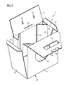
Figure 3 is a perspective view of a box element of the package ofFigure 1 ; -
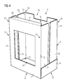
Figure 4 is a container supporting element of the package ofFigure 1 ; -
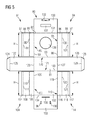
Figure 5 is a blank of packaging material, which can be folded to obtain the box element ofFigure 3 ; -
Figure 6 is a blank of packaging material, which can be folded to obtain the container supporting element ofFigure 4 . - With reference to
Figures 1 to 4 there is shown a package 1 for housing and transporting agroup 3 ofcontainers 2 of pourable food products. - More specifically, the
containers 2 in thegroup 3 are arranged in two superimposed layers. - The
containers 2 of each layer are arranged in a first row extending along a first direction F and a second row extending along a second direction G, parallel to the first direction F. - In the example shown, the first row and the second row contains each three
containers 2. - In this way, the
group 3 comprises twelvecontainers 2. - The
containers 2 are preferably sealed aseptically, contain a pourable food product, such as pasteurized or UHT milk, fruit juice, wine, etc., and are made of laminated strip packaging material, as described in detail above. - The package 1 comprises a
container supporting element 4 arranged to receive and retain thegroup 3 ofcontainers 2 and abox element 5 separate from thecontainer supporting element 4 and arranged to receive and retain thecontainer supporting element 4. - The
container supporting element 4 and thebox element 5 may be made from folded blanks, or units, made of cardboard or cardboard-based material, as better explained herebelow. - The
container supporting element 4 comprises abottom wall 6, and four side walls. - In particular, the
container supporting element 4 comprises a first side wall 7, asecond side wall 8, athird side wall 9 and afourth side wall 10. - The first side wall 7 and the
second side wall 8 face each other. - The
third side wall 9 and thefourth side wall 10 face each other. - The first side wall 7, the
second side wall 8, thethird side wall 9 and thefourth side wall 10 delimit aseat 11 arranged to house thegroup 3 ofcontainers 2. - The above-mentioned side walls form four corners.
- In particular, the first side wall 7 and the
third side wall 9 form afirst corner 12. The first side wall 7 and thefourth side wall 10 form asecond corner 13. Thesecond side wall 8 and thethird side wall 9 form athird corner 14. Thesecond side wall 8 and thefourth side wall 10 form afourth corner 15. - The first side wall 7 comprises an
aperture 16 through which a user can see thegroup 3 ofpackages 2, as better explained herebelow. - The
container supporting element 4 further comprises atop tab 17 extending from the first side wall 7. - When the
container supporting element 4 is housed in thebox element 5, thetop tab 17 is folded towards theseat 11 so as to increase the stiffness of the first wall 7. - The
container supporting element 4 comprises a firstside wall portion 18 extending from afirst edge portion 19 of the first side wall 7 and a secondside wall portion 20 extending from asecond edge portion 21, opposite to thefirst edge portion 19, of the first side wall 7. - The
container supporting element 4 further comprises a thirdside wall portion 22 extending from athird edge portion 23 of thesecond side wall 8 and a fourthside wall portion 24 extending from afourth edge portion 25, opposite to thefirst edge portion 23, of thesecond side wall 8. - The
container supporting element 4 further comprises afirst side flap 74 extending from afirst border 75 of thebottom wall 6 and asecond side flap 76 extending from asecond border 77, opposite to thefirst border 75, of thebottom wall 6. - The first
side wall portion 18 and the thirdside wall portion 22 are connected to thefirst side flap 74 so as to form thethird side wall 9. - The second
side wall portion 20 and the fourthside wall portion 24 are connected to thesecond side flap 76 so as to form thefourth side wall 10. - The
second side wall 8 comprises arecess 78 whose function will be better explained herebelow. Therecess 78 is positioned at a border zone of thesecond side wall 8 opposite to thebottom wall 6. - The
box element 5 comprises abottom face 26 and four side faces. - In particular, the
box element 5 comprises afirst side face 27, asecond side face 28, athird side face 29 and afourth side face 30. - The first side face 27 and the second side face 28 face each other.
- The third side face 29 and the fourth side face 30 face each other.
- The
first side face 27, thesecond side face 28, thethird side face 29 and thefourth side face 30 delimit acompartment 31 arranged to house thecontainer supporting element 4. - The first side face 7 comprises an
opening 46. - When the
container supporting element 4 is positioned inside thecompartment 31, theopening 46 and theaperture 16 are mutually aligned and face each other so that a user can see thegroup 3 ofpackages 2 through theopening 46 and theaperture 16. - The above-mentioned side faces form four corner areas.
- In particular, the
first side face 27 and thethird side face 29 form afirst corner area 32. Thefirst side face 27 and thefourth side face 30 form asecond corner area 33. Thesecond side face 28 and thethird side face 29 form athird corner area 34. Thesecond side face 28 and thefourth side face 30 form afourth corner area 35. - The
box element 5 comprises four spacers positioned at the four above-mentioned corner areas and arranged to interact with the four above-mentioned corners when thecontainer supporting element 4 is housed in thebox element 5. - In particular, the
box element 5 comprises afirst spacer 42 arranged at thefirst corner area 32, asecond spacer 43 arranged at thesecond corner area 33, athird spacer 44 arranged at thethird corner area 34 and afourth spacer 45 arranged at thefourth corner area 35. - The
container supporting element 4 is housed in thecompartment 31 so that the first side wall 7 faces thefirst side face 27, thesecond side wall 8 faces thesecond side face 28, thethird side wall 9 faces thethird side face 29 and thefourth side wall 10 faces thefourth side face 30. - A
first gap 47 is defined between the first side wall 7 and thefirst side face 27. - A
second gap 48 is defined between thesecond side wall 8 and thesecond side face 28. - A
third gap 49 is defined between thethird side wall 9 and thethird side face 29. - A
fourth gap 50 is defined between thefourth side wall 10 and thefourth side face 30. - The above-mentioned spacers are defined by appendices of the above-mentioned side faces.
- The above-mentioned appendices are bent inside the
compartment 31. - In particular, the
first spacer 42 is defined by afirst appendix 52 extending from afirst end zone 56 of thefirst end face 27. Thesecond spacer 43 is defined by asecond appendix 53 extending from asecond end zone 57, opposite to thefirst end zone 56, of thefirst end face 27. Thethird spacer 44 is defined by athird appendix 54 extending from athird end zone 58 of thesecond end face 28. Thefourth spacer 45 is defined by afourth appendix 55 extending from afourth end zone 59, opposite to thethird end zone 58, of thesecond side face 28. - Each appendix of the above-mentioned appendices comprises a portion extending from one of the above-mentioned side faces and connected to another one of the above-mentioned side faces adjacent to the side face from which the appendix projects, a further portion connected to the side portion from which the appendix projects and a still further portion, interposed between the portion and the further portion and arranged to contact a corresponding corner of the above-mentioned corners.
- The first portion is integral, i.e. made as a single piece, with the side face from which the appendix projects and is attached to the further side face adjacent to the side face from which the appendix projects and the further portion is attached to the side face from which the appendix projects.
- The portion may be connected to the side face adjacent to the side face from which the appendix project by gluing.
- The further potion may be connected to the side face from which the appendix project by gluing.
- In particular, the
first appendix 52 comprises afirst portion 60 connected to thethird side face 29, a firstfurther portion 61 connected thefirst side face 27 and a first stillfurther portion 62, interposed between thefirst portion 60 and the firstfurther portion 61 and arranged to contact thefirst corner 12. Thefirst portion 60 is substantially perpendicular to thefirst side face 27, the firstfurther portion 61 is substantially parallel to thefirst side face 27 and the first stillfurther portion 62 is inclined with respect to thefirst side face 27. In the embodiment shown, the first stillfurther portion 62 forms an angle of approximately 45 degrees with thefirst side face 27. - The
second appendix 53 comprises asecond portion 63 connected to thefourth side face 30, a secondfurther portion 64 connected thefirst side face 27 and a second stillfurther portion 65, interposed between thesecond portion 63 and the secondfurther portion 64 and arranged to contact thesecond corner 13. Thesecond portion 63 is substantially perpendicular to thefirst side face 27, the secondfurther portion 64 is substantially parallel to thefirst side face 27 and the first stillfurther portion 65 is inclined with respect to thefirst side face 27. In the embodiment shown, the second stillfurther portion 65 forms an angle of approximately 45 degrees with thefirst side face 27. - The
third appendix 54 comprises athird portion 66 connected to thethird side face 29, a thirdfurther portion 67 connected thesecond side face 28 and a third stillfurther portion 68, interposed between thethird portion 66 and the thirdfurther portion 67 and arranged to contact thethird corner 14. Thethird portion 66 is substantially perpendicular to thesecond side face 28, the thirdfurther portion 67 is substantially parallel to thesecond side face 28 and the third stillfurther portion 68 is inclined with respect to thesecond side face 28. In the embodiment shown, the third stillfurther portion 68 forms an angle of approximately 45 degrees with thesecond side face 28. - The
fourth appendix 55 comprises afourth portion 69 connected to thefourth side face 30, a fourthfurther portion 70 connected thesecond side face 28 and a fourth stillfurther portion 71, interposed between thefourth portion 69 and the fourthfurther portion 70 and arranged to contact thefourth corner 15. Thefourth portion 69 is substantially perpendicular to thesecond side face 28, the fourthfurther portion 70 is substantially parallel to thesecond side face 28 and the fourth stillfurther portion 71 is inclined with respect to thesecond side face 28. In the embodiment shown, the fourth stillfurther portion 71 forms an angle of approximately 45 degrees with thesecond side face 28. - The
box element 5 further comprises a firsttop face portion 36 extending from thefirst side face 27 and a secondtop face portion 37 extending from thesecond side wall 28. - When the
box element 5 is in a closed configuration, the firsttop face portion 36 is superimposed on the secondtop face portion 37 so that the firsttop face portion 36 and the secondtop face portion 37 form a top face of thebox element 5. - The first
top face portion 36 comprises alocking tab 38 arranged to be received and maintained in aslot 39 of the secondtop face portion 37 to keep thebox element 5 in the closed configuration. - When the
container supporting element 4 is housed in thebox element 5, therecess 78 prevents any interaction of the thelocking tab 38 with thesecond wall 8. - The second
top face portion 37 further comprises twoholes 40 arranged to receive end portions of a handle to be applied to thebox element 5. - The first
top face portion 36 further comprises afurther hole 41. - When the
box element 5 is in the closed configuration, the handle connected to the secondtop face portion 37 passes through thefurther hole 41 and projects from the top face. - The
box element 5 comprises aflap 72 extending from thethird side wall 29 and afurther flap 73 extending from thefourth side wall 30. - When the
box element 5 is in the closed configuration, theflap 72 projects toward thecompartment 31 and at least partially covers thefirst spacer 42 and thethird spacer 44. - Similarly, when the
box element 5 is in the closed configuration, thefurther flap 73 projects toward thecompartment 31 and at least partially covers thesecond spacer 43 and thefourth spacer 45. - When a user lifts the package 1 through the above-mentioned handle, the first
top face portion 36 and the secondtop face portion 37 may tend to bend upwardly. In this case, theflap 72 and thefurther flap 73 prevent access to thecompartment 31. -
Figure 5 shows a blank 80 of cardboard or cardboard-based material, which can be folded to obtain thebox element 5. - The blank 80 comprises a
base panel 81 arranged to form thebottom face 26 of thebox element 5. - The blank 80 further comprises a first side panel 82 adjacent to the
base panel 81 and arranged to form thefirst side face 27 of thebox element 5. - The first side panel 82 extends from a
first border portion 170 of thebase panel 81. - A
first crease line 83 extends between thebase panel 81 and the first side panel 82. - The blank 80 further comprises a
first appendix panel 84 extending from afirst edge 85 of the first side panel 82 adjacent to thefirst crease line 83. - The
first appendix panel 84 forms thefirst appendix 52 and, therefore, thefirst spacer 42. - The
first appendix panel 84 comprises afirst panel portion 86, a firstfurther panel portion 87 and a first stillfurther panel portion 88, arranged to form, respectively, thefirst portion 60, the firstfurther portion 61 and the first stillfurther portion 62. - A first another
crease line 89 is interposed between the first side panel 82 and thefirst panel portion 86. - A first further crease line 90 is interposed between the
first panel portion 86 and the first stillfurther panel portion 88. - A first still further crease line 91 is interposed between the first
further panel portion 87 and the first stillfurther panel portion 88. - The first another
crease line 89, the first further crease line 90 and the first still further crease line 91 are parallel to each other and perpendicular to thefirst crease line 83. - The
first panel portion 86, the firstfurther panel portion 87 and the first stillfurther panel portion 88 have each a rectangular shape and the same length H measured along a direction parallel to the first anothercrease line 89, the first further crease line 90 and the first still further crease line 91. - The
first panel portion 86 extends from the first side panel 82, the first stillfurther panel portion 88 extends from thefirst panel portion 86 and the firstfurther panel portion 87 extends from the first stillfurther panel portion 88. - The first side panel 82 comprises an
opening element 138 arranged to form theopening 46 of thebox element 5. - The blank 80 further comprises a
second appendix panel 94 extending from asecond edge 95, opposite to thefirst edge 85, of the first side panel 82 adjacent to thefirst crease line 83. - The
second appendix panel 94 forms thesecond appendix 53 and, therefore, thesecond spacer 43. - The
second appendix panel 94 comprises asecond panel portion 96, a secondfurther panel portion 97 and a second stillfurther panel potion 98, arranged to form, respectively, thesecond portion 63, the secondfurther portion 64 and the second stillfurther portion 65. - A second another
crease line 99 is interposed between the first side panel 82 and thesecond panel portion 96. - A second
further crease line 100 is interposed between thesecond panel portion 96 and the second stillfurther panel portion 98. - A second still
further crease line 101 is interposed between the secondfurther panel portion 97 and the second stillfurther panel portion 98. - The second another
crease line 99, the secondfurther crease line 100 and the second stillfurther crease line 101 are parallel to each other and perpendicular to thefirst crease line 83. - The
second panel portion 96, the secondfurther panel portion 97 and the second stillfurther panel portion 98 have each a rectangular shape and the same length H measured along a direction parallel to the second anothercrease line 99, the secondfurther crease line 100 and the second stillfurther crease line 101. - The
second panel portion 96 extends from the first side panel 82, the second stillfurther panel portion 98 extends from thesecond panel portion 96 and the secondfurther panel portion 97 extends from the second stillfurther panel portion 98. - The blank 80 further comprises a
second side panel 102 adjacent to thebase panel 81 and arranged to form thesecond side face 28 of thebox element 5. - The
second side panel 102 extends from asecond border portion 171, opposite to thefirst border portion 170, of thebase panel 81. - A
second crease line 103 extends between thebase panel 81 and thesecond side panel 102. - The blank 80 further comprises a
third appendix panel 104 extending from a furtherfirst edge 105 of thesecond side panel 102 adjacent to thesecond crease line 103. - The
third appendix panel 104 forms thethird appendix 54 and, therefore, thethird spacer 44. - The
third appendix panel 104 comprises athird panel portion 106, a thirdfurther panel portion 107 and a third stillfurther panel potion 108, arranged to form, respectively, thethird portion 66, the thirdfurther portion 67 and the third stillfurther portion 68. - A third another
crease line 109 is interposed between thesecond side panel 102 and thethird panel portion 106. - A third
further crease line 110 is interposed between thethird panel portion 106 and the third stillfurther panel portion 108. - A third still further crease line 111 is interposed between the third
further panel portion 107 and the third stillfurther panel portion 108. - The third another
crease line 109, the thirdfurther crease line 110 and the third still further crease line 111 are parallel to each other and perpendicular to thesecond crease line 103. - The
third panel portion 106, the thirdfurther panel portion 107 and the third stillfurther panel portion 108 have each a rectangular shape and the same length H measured along a direction parallel to the first anothercrease line 109, the secondfurther crease line 110 and the second still further crease line 111. - The
third panel portion 106 extends from thesecond side panel 102, the third stillfurther panel portion 108 extends from thethird panel portion 106 and the thirdfurther panel portion 107 extends from the third stillfurther panel portion 108. - The blank 80 further comprises a
fourth appendix panel 114 extending from a furthersecond edge 115, opposite to the furtherfirst edge 105, of thesecond side panel 102 adjacent to thesecond crease line 103. - The
fourth appendix panel 114 forms thefourth appendix 55 and, therefore, thefourth spacer 45. - The
fourth appendix panel 114 comprises afourth panel portion 116, a fourthfurther panel portion 117 and a fourth stillfurther panel potion 118, arranged to form, respectively, thefourth portion 69, the fourthfurther portion 70 and the fourth stillfurther portion 71. - A fourth another
crease line 119 is interposed between thesecond side panel 102 and thefourth panel portion 116. - A fourth further crease line 120 is interposed between the
fourth panel portion 116 and the fourth stillfurther panel portion 118. - A fourth still
further crease line 121 is interposed between the fourthfurther panel portion 117 and the fourth stillfurther panel portion 118. - The fourth another
crease line 119, the fourth further crease line 120 and the fourth stillfurther crease line 121 are parallel to each other and perpendicular to thesecond crease line 103. - The
fourth panel portion 116, the fourthfurther panel portion 117 and the fourth stillfurther panel portion 118 have each a rectangular shape and the same length H measured along a direction parallel to the fourth anothercrease line 119, the fourth further crease line 120 and the fourth stillfurther crease line 121. - The
fourth panel portion 116 extends from thesecond side panel 102, the fourth stillfurther panel portion 118 extends from thefourth panel portion 116 and the fourthfurther panel portion 117 extends from the fourth stillfurther panel portion 118. - The blank 80 further comprises a
third side panel 122 adjacent to thebase panel 81 and arranged to form the third side face 29 of thebox element 5. - A
crease line 123 extends between thebase panel 81 and thethird side panel 122. - The blank 80 further comprises a
flap panel 124 extending from thethird side panel 122 and arranged to form theflap 72 of thebox element 5. - A
crease line 125 extends between thethird side panel 122 and theflap panel 124. - The blank 80 further comprises a
fourth side panel 126 adjacent to thebase panel 81 and arranged to form the fourth side face 30 of thebox element 5. - A
crease line 127 extends between thebase panel 81 and thefourth side panel 126. - The blank 80 further comprises a
further flap panel 128 extending from thefourth side panel 126 and arranged to form thefurther flap 73 of thebox element 5. - A
crease line 129 extends between thefourth side panel 126 and thefurther flap panel 128. - The blank 80 further comprises a first
top panel portion 130 extending from the first side panel 82 and arranged to form the firsttop side portion 36 of thebox element 5. - A
crease line 131 extends between the first side panel 82 and the firsttop panel portion 130. - The first
top panel portion 130 comprises alocking tab panel 132 arranged to form thelocking tab 38 of thebox element 5. - The blank 80 further comprises a second
top panel portion 133 extending from thesecond side panel 102 and arranged to form the secondtop face portion 37 of thebox element 5. - A
crease line 134 extends between thesecond side panel 102 and the secondtop panel portion 133. - The second
top panel portion 133 comprises aslit element 135 arranged to form theslit 39 of the secondtop face portion 37. - The second
top panel portion 133 comprises twocutouts 136 arranged to form theholes 40 of the secondtop face portion 37. - The first
top panel portion 130 comprises afurther cutout 137 arranged to form thefurther hole 41 of the firsttop face portion 36. -
Figure 6 shows a blank 140 of cardboard or cardboard-based material, which can be folded to obtain thecontainer supporting element 4. - The blank 140 comprises a
base panel element 141 arranged to form thebottom wall 6 of thecontainer supporting element 4. - The blank 140 further comprises a first
side panel element 142 adjacent to thebase panel element 141 and arranged to form the first side wall 7 of thecontainer supporting element 4. - A
crease line 143 extends between thebase panel element 141 and the firstside panel element 142. - The blank 140 further comprises a second
side panel element 144 adjacent to thebase panel element 141 and arranged to form thesecond side wall 8 of thecontainer supporting element 4. - A
crease line 145 extends between thebase panel element 141 and the secondside panel element 144. - The first
side panel element 142 comprises anaperture element 146 arranged to form theaperture 16 of thecontainer supporting element 4. - The second
side panel element 144 comprises arecess element 147 arranged to form therecess 78 of thecontainer supporting element 4. - The blank 140 further comprises a top
tab panel element 148 extending from the firstside panel element 142 and arranged to form thetop tab 17 of thecontainer supporting element 4. - A
crease line 149 is interposed between the firstside panel element 142 and the toptab panel element 148. - The blank 140 further comprises a first side
portion panel element 150 extending from afirst edge portion 151 of the firstside panel element 142 adjacent to thecrease line 143 and arranged to form the firstside wall portion 18 of thecontainer supporting element 4. - A
crease line 152 is interposed between the first sidepanel portion element 150 and the firstside panel element 142. - The blank 140 further comprises a second side
portion panel element 153 extending from asecond edge portion 154, opposite to thefirst edge portion 151, of the firstside panel element 142 adjacent to thecrease line 143 and arranged to form the secondside wall portion 20 of thecontainer supporting element 4. - A
crease line 155 is interposed between the second sidepanel portion element 153 and the firstside panel element 142. - The blank 140 further comprises a third side
portion panel element 156 extending from a furtherfirst edge portion 157 of the secondside panel element 144 adjacent to thecrease line 145 and arranged to form the thirdside wall portion 22 of thecontainer supporting element 4. - A
crease line 158 is interposed between the third sidepanel portion element 156 and the secondside panel element 144. - The blank 140 further comprises a fourth side
portion panel element 159 extending from a furthersecond edge portion 160, opposite to the furtherfirst edge portion 157, of the secondside panel element 144 adjacent to thecrease line 145 and arranged to form the fourthside wall portion 24 of thecontainer supporting element 4. - A
crease line 161 is interposed between the fourth sidepanel portion element 159 and the secondside panel element 144. - The blank 140 further comprises a first side
flap panel element 162 adjacent to thebase panel element 141 and arranged to form thefirst side flap 74 of thecontainer supporting element 4. - A
crease line 163 extends between thebase panel element 141 and the first sideflap panel element 162. - The blank 140 further comprises a second side
flap panel element 164 adjacent to thebase panel element 141 and arranged to form thesecond side flap 76 of thecontainer supporting element 4. - A
crease line 165 extends between thebase panel element 141 and the second sideflap panel element 164. - During operation, a
group 3 of containers is placed on the blank 140, in particular on thebase panel element 141, and the blank 140 is wrapped around thegroup 3 ofcontainers 2 so as to form thecontainer supporting element 4. - Subsequently, the
container supporting element 4 is placed on the blank 80, in particular on thebase panel 81, and the blank 80 is wrapped around the supportingelement 4 so as to form thebox element 5 and obtain a folded, filled and sealed package 1. - In particular, while the blank 80 is wrapped around the
container supporting element 4, the above-mentioned appendices are folded so as to form the above-mentioned spacers. - All the operations disclosed above may be carried out automatically, through dedicated packaging machines.
- Owing to the invention, it is possible to obtain a package in which the spacers are made during folding of the box element and do not need to be provided as separate parts.
- In addition, there is no need do manufacture the spacers separately from the box element and insert the spacers into the pre-folded box element.
- In particular, there is no need to manually position the spacers into the box element as in the known packages.
- The spacers, in fact, are made at the same time as the box element and from the same blank.
- In this way, the package is manufactured and filled with containers in a much easier way with respect to the known packages.
- In addition, since the box element and the spacers are made of the same material, for example cardboard or cardboard-based material, disposal and recycling of the package are extremely simple.
- Clearly, changes may be made to package 1 according to the present invention without, however, departing from the scope as defined in the accompanying claims.
Claims (14)
- A package for containers (2) of pourable food, comprising a container supporting element (4) arranged to receive and retain said containers (2) and a box element (5) separate from said container supporting element (4) and arranged to receive and retain said container supporting element (4), said container supporting element (4) having an end wall (6) and a plurality of side walls (7, 8, 9, 10) that delimit a seat (11) arranged to house said containers (2), said side walls (7, 8, 9, 10) forming a plurality of corners (12, 13, 14, 15), said box element (5) comprising an end face (26) and a plurality of side faces (27, 28, 29, 30) that delimit a compartment (31) arranged to house said container supporting element (4), said side faces (27, 28, 29, 30) forming a plurality of corner areas (32, 33, 34, 35), said package (1) further comprising a plurality of spacers (42, 43, 44, 45) arranged at said corner areas (32, 33, 34, 35) and interacting with said corners (12, 13, 14, 15) when said container supporting element (4) is housed in said compartment (31) so that each side wall (7, 8, 9, 10) of said side walls faces a corresponding side face (27, 28, 29, 30) of said side faces and a corresponding gap (47, 48, 49, 50) is defined between said each side wall (7, 8, 9, 10) and said corresponding side face (27, 28, 29, 30).
- A package according to claim 1, wherein said spacers (42, 43, 44, 45) are defined by appendices (52, 53, 54, 55) of said side faces (27, 28, 29, 30) bent inside said compartment (31).
- A package according to claim 2, wherein each appendix (52, 53, 54, 55) of said appendices comprises a portion (60, 63, 66, 69) extending from a side face (27, 28, 29, 30) of said side faces and connected to a further side face (27, 28, 29, 30) of said side faces adjacent to said side face (27, 28, 29, 30) from which said appendix (52, 53, 54, 55) projects, a further portion (61, 64, 68, 71) connected to said side face (27, 28, 29, 30) from which said appendix (52, 53, 54, 55) projects and a still further portion (62, 65, 68, 71), interposed between said portion (60, 63, 66, 69) and said further portion (61, 64, 67, 70) and arranged to contact a corresponding corner (12, 13, 14, 15) of said corners.
- A package according to claim 3, wherein said portion (60, 63, 66, 69) is integral with said side face (27, 28, 29, 30) from which said appendix (52, 53, 54, 55) projects and is attached to said further side face (27, 28, 29, 30) adjacent to said side face (27, 28, 29, 30) from which said appendix (52, 53, 54, 55) projects and said further appendix (61, 64, 67, 70) is attached to said side face (27, 28, 29, 30) from which said appendix (52, 53, 54, 55) projects.
- A package according to claim 3, or 4, wherein said portion (60, 63, 66, 69) is substantially perpendicular to said side face (27, 28, 29, 30) from which said appendix (52, 53, 54, 55) projects, said further portion (61, 64, 67, 70) is substantially parallel to said side face (27, 28, 29, 30) from which said appendix (52, 53, 54, 55) projects and said still further portion (62, 65, 68, 71) is inclined with respect to said side face (27, 28, 29, 30) from which said appendix (52, 53, 54, 55) projects.
- A package according to any one of claims 2 to 5, wherein said side faces comprises a couple of first side faces (27, 28) facing each other and a couple of second side faces (29, 30) facing each other, a couple of appendices (52, 53; 54, 55) projecting from opposite end zones (56, 57; 58, 59) of each first side face (27; 28) of said couple of first side faces (27, 28).
- A package according to claim 6, wherein each first side face (27; 28) comprises a first appendix (52; 54) of said couple of appendices extending from a first end zone (56; 58) of said opposite and zones, said first appendix (52; 54) comprising a first portion (60; 66) extending from said first side face (27; 28) and attached to one second side face (29) of said couple of second side faces, a first further portion (61; 67) attached to said first side face (27; 28) and a still further portion (62; 68) interposed between said portion (60; 66) and said further portion (61; 67) and wherein each first side face (27, 28) comprises a second appendix (53; 55) of said couple of appendices extending from a second end zone (57; 59) of said opposite and zones, said second appendix (53; 55) comprising a second portion (63; 69) extending from said first side face (27; 28) and attached to another second side face (30) of said couple of second side faces, a second further portion (64; 70) attached to said first side face (27; 28) and a second still further portion (65; 71) interposed between said second portion (63; 69) and said second further portion (64; 70).
- A blank of packaging material for producing a box element (5) of a package (1) for containers (2) of pourable food, comprising a base panel (81) arranged to form an end face (26) of said box element (5), a side panel (82; 102) adjacent to said base panel (81) and arranged to form a side face (27; 28) of said box element (5), a crease line (83; 103) extending between said base panel (81) and said side panel (82; 102), said blank (80) further comprising an appendix panel (84; 94; 104; 114) extending from an edge (85; 95; 105; 115) of said side panel (82; 102) adjacent to said first crease line (83; 103), said appendix panel (84; 94; 104; 114) comprising a panel portion (86; 96; 106; 116), a further panel portion (87; 97; 107; 117) and a still further panel potion (88; 98; 108; 118), which are arranged to form a spacer (42; 43; 44; 45) of said box element (5), another crease line (89; 99; 109; 119) being interposed between said side panel (82; 102) and said panel portion (86; 96; 106; 116), a further crease line (90; 100; 110; 120) being interposed between said panel portion (86; 96; 106; 116) and said still further panel portion (88; 98; 108; 118) and a still further crease line (91; 101; 111; 121) being interposed between said further panel portion (87; 97; 107; 117) and said still further panel portion (88; 98; 108; 118), said another crease line (89; 99; 109; 119), said further crease line (90; 100; 110; 120) and said still further crease line (91; 101; 111; 121) being parallel to each other and perpendicular to said crease line (83; 103).
- A blank according to claim 8, wherein said panel portion (86; 96; 106; 116), said further panel portion (87; 97; 107; 117) and said still further panel portion (88; 98; 108; 118) have each a rectangular shape and a same length (H) measured along a direction parallel to said another crease line (89; 99; 109; 119), said further crease line (90; 100; 110; 120) and said still further crease line (91; 101; 111; 121).
- A blank according to claim 8, or 9, wherein said panel portion (86; 96; 106; 116) extends from said side panel (82; 102), said still further panel portion (88; 98; 108; 118) extends from said panel portion (86; 96; 106; 116) and said further panel portion (87; 97; 107; 117) extends from said still further panel portion (88; 98; 108; 118).
- A blank according to any one of claim 8 to 10, wherein a first side panel (82), arranged to form a first side face (27) of said box element (5), extends from a first border portion (170) of said base panel (81) and a second side panel (102), arranged to form a second side face (28) of said box element (5), extends from a second border portion (171), opposite to said first border portion (170), of said base panel (81).
- A blank according to claim 11, wherein a first crease line (83) is interposed between said base panel (81) and said first side panel (82) and a second crease line (103) is interposed between said base panel (81) and said second side panel (102).
- A blank according to claim 11, or 12, wherein a first appendix panel (84), arranged to form a first appendix (52) of said first side face (27), extends from a first edge (85) of said first side panel (82), a second appendix panel (94), arranged to form a second appendix (53) of said first side face (27), extends from a second edge (95), opposite to said first edge (85), of said first side panel (82), a third appendix panel (104), arranged to form a third appendix (52) of said second side face (28), extends from a further first edge (105) of said second side panel (102) and a fourth appendix panel (114), arranged to form a fourth appendix (52) of said second side face (28), extends from a further second edge (115), opposite to said further first edge (105), of said second side panel (102).
- A blank according to claim 13, wherein a first another crease line (89) is interposed between said first side panel (82) and said first appendix panel (84), a second another crease line (99) is interposed between said first side panel (82) and said second appendix panel (94), a third another crease line (109) is interposed between said second side panel (102) and said third appendix panel (104) and a fourth another crease line (119) is interposed between said second side panel (102) and said fourth appendix panel (114).
Priority Applications (2)
| Application Number | Priority Date | Filing Date | Title |
|---|---|---|---|
| EP14193299.6A EP3020644A1 (en) | 2014-11-14 | 2014-11-14 | Package for containers of pourable food products |
| CN201510744987.2A CN105600063A (en) | 2014-11-14 | 2015-11-05 | Package for containers of pourable food products |
Applications Claiming Priority (1)
| Application Number | Priority Date | Filing Date | Title |
|---|---|---|---|
| EP14193299.6A EP3020644A1 (en) | 2014-11-14 | 2014-11-14 | Package for containers of pourable food products |
Publications (1)
| Publication Number | Publication Date |
|---|---|
| EP3020644A1 true EP3020644A1 (en) | 2016-05-18 |
Family
ID=51900775
Family Applications (1)
| Application Number | Title | Priority Date | Filing Date |
|---|---|---|---|
| EP14193299.6A Withdrawn EP3020644A1 (en) | 2014-11-14 | 2014-11-14 | Package for containers of pourable food products |
Country Status (2)
| Country | Link |
|---|---|
| EP (1) | EP3020644A1 (en) |
| CN (1) | CN105600063A (en) |
Cited By (1)
| Publication number | Priority date | Publication date | Assignee | Title |
|---|---|---|---|---|
| WO2018177749A1 (en) * | 2017-03-27 | 2018-10-04 | Tetra Laval Holdings & Finance S.A. | Machine and method for producing packages of containers, in particular containers of pourable food products |
Families Citing this family (1)
| Publication number | Priority date | Publication date | Assignee | Title |
|---|---|---|---|---|
| CN108001782A (en) * | 2017-12-20 | 2018-05-08 | 汤克辉 | A kind of packing case easy to open |
Citations (4)
| Publication number | Priority date | Publication date | Assignee | Title |
|---|---|---|---|---|
| GB190918686A (en) * | 1909-08-13 | 1910-01-20 | Alfred Julius Boult | Improvements in or relating to Packing or Shipping Boxes. |
| JPH0510228U (en) * | 1991-07-18 | 1993-02-09 | 本州製紙株式会社 | Packing ball box |
| JP2000016421A (en) * | 1998-06-30 | 2000-01-18 | Toshiba Tec Corp | Packaging device |
| JP2010143634A (en) * | 2008-12-22 | 2010-07-01 | Kao Corp | Packaging box |
Family Cites Families (5)
| Publication number | Priority date | Publication date | Assignee | Title |
|---|---|---|---|---|
| US7413111B2 (en) * | 2002-02-15 | 2008-08-19 | International Paper Company | Paperboard container with bottom support |
| CN2631958Y (en) * | 2003-08-01 | 2004-08-11 | 广达电脑股份有限公司 | Packing cases |
| CN101475067B (en) * | 2008-01-04 | 2011-03-23 | 佛山普立华科技有限公司 | Packing box |
| CN202226118U (en) * | 2011-08-26 | 2012-05-23 | 深圳市裕同印刷股份有限公司 | Package carton for electronic product |
| CN102887296B (en) * | 2012-10-26 | 2015-09-09 | 周学义 | A kind of resistance to compression melon and fruit packing chest |
-
2014
- 2014-11-14 EP EP14193299.6A patent/EP3020644A1/en not_active Withdrawn
-
2015
- 2015-11-05 CN CN201510744987.2A patent/CN105600063A/en active Pending
Patent Citations (4)
| Publication number | Priority date | Publication date | Assignee | Title |
|---|---|---|---|---|
| GB190918686A (en) * | 1909-08-13 | 1910-01-20 | Alfred Julius Boult | Improvements in or relating to Packing or Shipping Boxes. |
| JPH0510228U (en) * | 1991-07-18 | 1993-02-09 | 本州製紙株式会社 | Packing ball box |
| JP2000016421A (en) * | 1998-06-30 | 2000-01-18 | Toshiba Tec Corp | Packaging device |
| JP2010143634A (en) * | 2008-12-22 | 2010-07-01 | Kao Corp | Packaging box |
Cited By (2)
| Publication number | Priority date | Publication date | Assignee | Title |
|---|---|---|---|---|
| WO2018177749A1 (en) * | 2017-03-27 | 2018-10-04 | Tetra Laval Holdings & Finance S.A. | Machine and method for producing packages of containers, in particular containers of pourable food products |
| EP3381819A3 (en) * | 2017-03-27 | 2018-10-17 | Tetra Laval Holdings & Finance S.A. | Machine and method for producing packages of containers, in particular containers of pourable food products |
Also Published As
| Publication number | Publication date |
|---|---|
| CN105600063A (en) | 2016-05-25 |
Similar Documents
| Publication | Publication Date | Title |
|---|---|---|
| EP3656689B1 (en) | A sheet packaging material for producing a sealed package containing a pourable product and a package obtained therefrom | |
| US9463896B2 (en) | Carton with opening feature | |
| EP3010814B1 (en) | Wraparound shipping box blank with system and method of forming blank into a shipping case | |
| EP3219633B1 (en) | A sheet packaging material | |
| RU2690275C1 (en) | Self-converging polygonal sealed box for food products and tool for its formation | |
| JP2021502313A (en) | Stackable product packages, how to make them, and product package blanks | |
| JP7262483B2 (en) | Sheet packaging material for making sealed packages containing liquid foodstuffs and sealed packages derived from sheet packaging material | |
| US20160325872A1 (en) | Sealed package for pourable food products and a basic unit of sheet packaging material for producing sealed packages for pourable food products | |
| JP2022513450A (en) | Product package and its manufacturing method and package blank | |
| US10301063B2 (en) | Package material and package container formed with said material | |
| EP3556673B1 (en) | A sealed package containing a pourable food product and a sheet packaging material for producing a sealed package containing a pourable food product | |
| EP3020644A1 (en) | Package for containers of pourable food products | |
| CA3108498C (en) | Tray with nesting anti-lock feature | |
| EP3141490A1 (en) | Package for containers of pourable food products | |
| US11932461B2 (en) | Sheet packaging material for producing sealed packages for liquid food products | |
| WO2024027992A1 (en) | Packaging blank for forming a package and package formed from a packaging blank | |
| WO2024027991A1 (en) | Packaging blank for forming a package and package formed from a packaging blank | |
| ITTO20080052U1 (en) | PACKAGE FOR CONTAINERS OF VERSABLE FOOD PRODUCTS | |
| ITTO20080055U1 (en) | PACKAGE FOR CONTAINERS OF VERSABLE FOOD PRODUCTS |
Legal Events
| Date | Code | Title | Description |
|---|---|---|---|
| PUAI | Public reference made under article 153(3) epc to a published international application that has entered the european phase |
Free format text: ORIGINAL CODE: 0009012 |
|
| AK | Designated contracting states |
Kind code of ref document: A1 Designated state(s): AL AT BE BG CH CY CZ DE DK EE ES FI FR GB GR HR HU IE IS IT LI LT LU LV MC MK MT NL NO PL PT RO RS SE SI SK SM TR |
|
| AX | Request for extension of the european patent |
Extension state: BA ME |
|
| STAA | Information on the status of an ep patent application or granted ep patent |
Free format text: STATUS: THE APPLICATION IS DEEMED TO BE WITHDRAWN |
|
| 18D | Application deemed to be withdrawn |
Effective date: 20161119 |