JP5522401B2 - Image forming apparatus - Google Patents
Image forming apparatus Download PDFInfo
- Publication number
- JP5522401B2 JP5522401B2 JP2010284955A JP2010284955A JP5522401B2 JP 5522401 B2 JP5522401 B2 JP 5522401B2 JP 2010284955 A JP2010284955 A JP 2010284955A JP 2010284955 A JP2010284955 A JP 2010284955A JP 5522401 B2 JP5522401 B2 JP 5522401B2
- Authority
- JP
- Japan
- Prior art keywords
- recording material
- unit
- reversing
- image forming
- forming apparatus
- Prior art date
- Legal status (The legal status is an assumption and is not a legal conclusion. Google has not performed a legal analysis and makes no representation as to the accuracy of the status listed.)
- Active
Links
Images


Classifications
-
- G—PHYSICS
- G03—PHOTOGRAPHY; CINEMATOGRAPHY; ANALOGOUS TECHNIQUES USING WAVES OTHER THAN OPTICAL WAVES; ELECTROGRAPHY; HOLOGRAPHY
- G03G—ELECTROGRAPHY; ELECTROPHOTOGRAPHY; MAGNETOGRAPHY
- G03G15/00—Apparatus for electrographic processes using a charge pattern
- G03G15/22—Apparatus for electrographic processes using a charge pattern involving the combination of more than one step according to groups G03G13/02 - G03G13/20
- G03G15/23—Apparatus for electrographic processes using a charge pattern involving the combination of more than one step according to groups G03G13/02 - G03G13/20 specially adapted for copying both sides of an original or for copying on both sides of a recording or image-receiving material
- G03G15/231—Arrangements for copying on both sides of a recording or image-receiving material
- G03G15/232—Arrangements for copying on both sides of a recording or image-receiving material using a single reusable electrographic recording member
- G03G15/234—Arrangements for copying on both sides of a recording or image-receiving material using a single reusable electrographic recording member by inverting and refeeding the image receiving material with an image on one face to the recording member to transfer a second image on its second face, e.g. by using a duplex tray; Details of duplex trays or inverters
-
- G—PHYSICS
- G03—PHOTOGRAPHY; CINEMATOGRAPHY; ANALOGOUS TECHNIQUES USING WAVES OTHER THAN OPTICAL WAVES; ELECTROGRAPHY; HOLOGRAPHY
- G03G—ELECTROGRAPHY; ELECTROPHOTOGRAPHY; MAGNETOGRAPHY
- G03G2215/00—Apparatus for electrophotographic processes
- G03G2215/00362—Apparatus for electrophotographic processes relating to the copy medium handling
- G03G2215/00535—Stable handling of copy medium
- G03G2215/00556—Control of copy medium feeding
- G03G2215/00586—Control of copy medium feeding duplex mode
Description
本願発明は、複数枚の記録材を循環搬送しながら両面印刷できる画像形成装置に関するものである。画像形成装置には、複写機、プリンタ、ファクシミリ及びこれらの機能を複合的に備えた複合機といった各種のものが含まれる。 The present invention relates to an image forming apparatus capable of duplex printing while circulating and conveying a plurality of recording materials. The image forming apparatus includes various apparatuses such as a copying machine, a printer, a facsimile machine, and a multifunction machine having these functions in combination.
従来から、電子写真方式を採用した画像形成装置では、画像プロセス部にて片面に印刷(画像形成)された後の記録材を反転部にて表裏反転させ、表裏反転した記録材を画像プロセス部に再給紙して記録材の他面に印刷することによって、記録材の両面印刷を行っている。複数枚の記録材を連続して両面印刷する際は、所定枚数を1単位として片面印刷と他面印刷とが交互に実行される。例えば所定枚数が4枚であれば、記録材4枚を連続して片面印刷してから、表裏反転させて循環搬送し、記録材4枚の他面印刷を行う。 2. Description of the Related Art Conventionally, in an image forming apparatus employing an electrophotographic method, a recording material that has been printed on one side (image formation) by an image processing unit is reversed at the reversing unit, and the recording material that has been reversed upside down is image processing unit. The sheet is fed again and printed on the other side of the recording material to perform double-sided printing of the recording material. When double-sided printing is continuously performed on a plurality of recording materials, single-sided printing and other-sided printing are alternately performed with a predetermined number of sheets as one unit. For example, if the predetermined number of sheets is four, four recording materials are continuously printed on one side, and then are reversed and conveyed in a circulatory manner to perform printing on the other surface of the four recording materials.
所定枚数は、記録材が循環搬送される経路中に記録材を同時に収容できる最大枚数を意味している(以下の説明では循環枚数と称する)。循環枚数は基本的に、前記経路の全長と記録材の搬送方向長さとの関係から定まるものである。例えば特許文献1には、記録材のサイズ及び紙種から循環枚数を設定し、設定された循環枚数に従って、複数枚の記録材を連続して両面印刷する画像形成装置が開示されている。
The predetermined number of sheets means the maximum number of sheets that can simultaneously accommodate the recording material in the path through which the recording material is circulated (referred to as the “circulated number” in the following description). The number of circulating sheets is basically determined from the relationship between the total length of the path and the length of the recording material in the conveyance direction. For example,
ところで一般に、前記経路の全長は、最も使用頻度の高い記録材(例えばA4縦)の循環搬送において最も両面生産性が高まるように設定される。換言すると、前記経路はA4縦の循環搬送を基準に設計される。例えばA4縦の循環枚数を5枚とした場合は、5枚目の記録材の片面を印刷した直後に、引き続き1枚目の記録材の他面が印刷されるように、前記経路の全長を設定するのである。両面生産性が高い状態とは、連続両面印刷時における後尾の記録材と先頭の記録材との搬送間隔が、連続片面印刷時における記録材の搬送間隔とあまり変わらず、連続両面印刷の効率が連続片面印刷の効率(片面生産性)と同程度の状態である。なお、A4縦の搬送では記録材の短辺方向が搬送方向になり、この場合の搬送方向長さは210mmである。 In general, the total length of the path is set so that the double-sided productivity is the highest in the circulation conveyance of the most frequently used recording material (for example, A4 length). In other words, the path is designed based on A4 vertical circulation conveyance. For example, if the A4 vertical circulation number is 5, the total length of the path is set so that the other side of the first recording material is printed immediately after printing one side of the fifth recording material. Set it. High duplex production means that the conveyance interval between the trailing recording material and the leading recording material in continuous duplex printing is not much different from the conveyance interval of recording material in continuous single-sided printing, and the efficiency of continuous duplex printing is high. This is the same level of efficiency as single-sided printing (single-sided productivity). In the A4 vertical conveyance, the short side direction of the recording material is the conveyance direction. In this case, the conveyance direction length is 210 mm.
前記従来技術では、搬送方向長さがA4縦よりも長い記録材(例えばA4横やB4横)の複数枚を両面印刷する場合、A4縦の循環枚数よりも少ない循環枚数が設定される。なぜなら、仮にA4横の循環枚数をA4縦と同じにすると、A4横の搬送方向長さ(297mm)がA4縦のそれ(210mm)よりも長いことに起因して、前記経路内で先頭の記録材が後尾の記録材に追突するという不具合が生ずるためである。 In the conventional technique, when a plurality of recording materials (for example, A4 landscape or B4 landscape) whose length in the conveyance direction is longer than A4 portrait are printed on both sides, a circulated number less than the A4 portrait circulate is set. This is because if the A4 horizontal circulation number is the same as the A4 vertical, the length of the A4 horizontal conveyance direction (297 mm) is longer than that of the A4 vertical (210 mm), so that the first recording in the path This is because there is a problem that the material collides with the trailing recording material.
しかし、前記従来技術では、搬送方向長さがA4縦より数mm程度長いだけの記録材についても、その循環枚数を少なくするため、後尾の記録材と先頭の記録材との搬送間隔が大きく空くことになり、このような場合の両面生産性が著しく低下するという問題があった。本願発明は、上記の問題点を解消した画像形成装置を提供することを技術的課題とするものである。 However, in the above-described prior art, even for a recording material whose transport direction length is only a few millimeters longer than the A4 length, in order to reduce the number of circulating sheets, the transport interval between the trailing recording material and the leading recording material is large. In other words, the double-sided productivity in such a case is significantly reduced. An object of the present invention is to provide an image forming apparatus that solves the above problems.
本願発明の画像形成装置は、画像プロセス部にて片面に印刷された後の記録材を表裏反転させる反転部と、表裏反転した前記記録材を前記画像プロセス部に再給紙するための循環搬送部と、印刷動作を制御する制御部とを備えている画像形成装置であって、前記反転部を複数有しており、前記制御部は、複数枚の記録材を前記循環搬送部にて循環搬送して両面印刷する場合に、前記記録材の少なくとも1枚を前記反転部にて待機させ、前記反転部で前記記録材を待機させた状態で他の記録材を前記記録材の待機が実行されていない反転部と前記循環搬送部とで循環させ、前記記録材の待機が実行されていない反転部を前記他の記録材が通過した後に、前記記録材を待機させていた反転部における前記記録材の待機を解除し、循環搬送される前記記録材の実循環枚数を、前記記録材の搬送方向長さに応じて定まる規定循環枚数より前記待機枚数分増加させる。 An image forming apparatus according to the present invention includes a reversing unit for reversing a recording material after printing on one side in an image processing unit, and a circulating conveyance for refeeding the recording material that has been reversed to the front and back to the image processing unit. An image forming apparatus including a plurality of reversing units, and the control unit circulates a plurality of recording materials in the circulation conveyance unit. When transporting and duplex printing, at least one of the recording materials waits at the reversing unit, and the recording material waits at the recording material while the recording material waits at the reversing unit. The reversing unit that is circulated between the reversing unit that has not been performed and the recirculation conveyance unit, and the reversing unit that has been waiting for the recording material after the other recording material has passed through the reversing unit that has not been waiting for the recording material It cancels the paused recording material, prior to being circulated and conveyed The actual circulation quantity of the recording material, the waiting number of sheets is increased than the standard circulation number determined in accordance with the length in the conveyance direction of the recording material.
本願発明の画像形成装置は、上記画像形成装置において、前記制御部は、前記反転部での記録材待機に伴う記録材排紙順序に応じて、印刷される画像順を入れ換えるというものである。 In the image forming apparatus according to the present invention, in the image forming apparatus, the control unit changes a printed image order in accordance with a recording material discharge order associated with recording material standby in the reversing unit.
本願発明の画像形成装置は、上記画像形成装置において、前記反転部を2つ有しており、前記両反転部の一方が印刷済の記録材を排出する排出部を兼用しているというものである。 The image forming apparatus according to the present invention is the image forming apparatus described above, wherein the image forming apparatus has two reversing portions, and one of the reversing portions also serves as a discharge portion that discharges a printed recording material. is there.
本願発明の画像形成装置は、上記画像形成装置において、印刷指令に含まれる受信枚数が(前記規定循環枚数+1)よりも少ない場合、前記制御部は前記反転部での記録材待機を行わずに前記実循環枚数を前記規定循環枚数とするというものである。 In the image forming apparatus of the present invention, in the image forming apparatus, when the number of received sheets included in the print command is smaller than (the specified circulation number + 1), the control unit does not wait for the recording material in the reversing unit. The actual circulation number is set as the specified circulation number.
本願発明の画像形成装置は、上記画像形成装置において、前記記録材の搬送方向長さが規定長さであり且つ予定印刷枚数が(前記規定循環枚数+1)の倍数である場合、前記制御部は前記反転部での記録材待機を行って前記実循環枚数を(前記規定循環枚数+1)とするというものである。 In the image forming apparatus according to the present invention, in the image forming apparatus, when the length of the recording material in the conveyance direction is a specified length and the planned number of printed sheets is a multiple of (the specified number of circulation sheets + 1), The recording material standby at the reversing unit is performed, and the actual circulation number is set to (the prescribed circulation number + 1).
本願発明の画像形成装置は、上記画像形成装置において、前記記録材の搬送方向長さ又は紙種、各種印刷モード、或いはプロセス速度といった印刷動作条件が途中で変更される場合、前記制御部は前記反転部での記録材待機を禁止するというものである。 In the image forming apparatus according to the present invention, in the image forming apparatus, when a printing operation condition such as a length or a paper type of the recording material, various printing modes, or a process speed is changed halfway, the control unit The recording material standby at the reversing part is prohibited.
本願発明の画像形成装置は、上記画像形成装置において、前記反転部で待機中の記録材が機外に露出している場合、前記制御部はこれに接続された報知手段にて前記待機中の記録材の除去を禁止する旨を報知するというものである。 In the image forming apparatus according to the present invention, in the image forming apparatus, when the recording material waiting in the reversing unit is exposed to the outside of the apparatus, the control unit is in the waiting state by an informing means connected thereto. This is to notify that the removal of the recording material is prohibited.
本願の請求項に記載された発明によると、複数枚の記録材を循環搬送部にて循環搬送して両面印刷する場合において、前記記録材の少なくとも1枚を反転部にて待機させ、循環搬送される前記記録材の実循環枚数を、前記記録材の搬送方向長さに応じて定まる規定循環枚数より前記待機枚数分増加させるから、前記規定循環枚数で循環搬送させた場合に比べて、後尾の記録材と先頭の記録材との搬送間隔の空き、すなわちタイムラグの発生回数を少なくできる。このため、単位時間当りの印刷枚数が増え、前記記録材の搬送方向長さの相違に起因した両面生産性の低下を抑制できるという効果を奏する。 According to the invention described in the claims of the present application, in the case where a plurality of recording materials are circulated and conveyed by the circulatory conveyance unit to perform double-sided printing, at least one of the recording materials is kept waiting at the reversal unit, and circulated The actual circulation number of the recording material is increased by the standby number from the specified circulation number determined according to the length of the recording material in the conveyance direction. This makes it possible to reduce the gap between the recording material and the leading recording material, that is, the number of occurrences of time lag. For this reason, the number of printed sheets per unit time increases, and it is possible to suppress the decrease in double-sided productivity due to the difference in the length of the recording material in the conveyance direction.
また、前記制御部が、前記反転部での記録材待機に伴う記録材排紙順序に応じて、印刷される画像順を入れ換えるので、前記記録材を画像順毎に排出でき、前記記録材の排紙順と、前記各記録材に印刷された画像順との並び関係にズレが生じない。従って、ユーザにとっての利便性を維持できるという効果を奏する。 In addition, since the control unit changes the order of the printed images according to the recording material discharge order accompanying the recording material standby in the reversing unit, the recording material can be discharged for each image order. There is no deviation in the arrangement relationship between the discharge order and the order of images printed on the recording materials. Therefore, there is an effect that the convenience for the user can be maintained.
以下に、本願発明を画像形成装置の一例であるタンデム方式のカラーデジタルプリンタ(以下、プリンタと称する)に適用した実施形態を、図面に基づいて説明する。 Hereinafter, an embodiment in which the present invention is applied to a tandem color digital printer (hereinafter referred to as a printer), which is an example of an image forming apparatus, will be described with reference to the drawings.
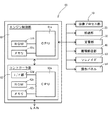
図1に示すように、プリンタ1は循環式の両面印刷機能を有するものであり、画像プロセス部10、給送部20、定着部30、循環搬送部40、制御部60等を備えている。図示は省略するが、プリンタ1は、例えばLANといったネットワークに接続されていて、外部端末からの印刷指令を受け付けると、当該印刷指令に基づいて印刷ジョブを実行するように構成されている。印刷ジョブには、記録材Pの片面に印刷(画像形成)する片面モードによるジョブと、記録材Pの片面及び他面に印刷する両面モードによるジョブとが含まれる。
As shown in FIG. 1, the
画像プロセス部10は、像担持体の一例である感光体ドラム3上に形成されたトナー像を記録材Pに転写する役割を担うものであり、イエロー(Y)、マゼンタ(M)、シアン(C)及びブラック(K)の各色に対応する計4つの作像部2、及び中間転写ベルト11等を備えている。4つの作像部2は、中間転写ベルト11の下方において、図1の左からイエロー、マゼンタ、シアン、ブラック)の順に、中間転写ベルト11に沿って並べて配置されている。各作像部2は、図1の時計方向に回転駆動する感光体ドラム3を有している。感光体ドラム3の周囲には、その回転方向(図1の時計方向)に沿って順に、帯電部4、露光部5、現像部6、一次転写ローラ7、及び感光体クリーナ8が配置されている。なお、図1では説明の便宜上、各作像部2に、再現色に応じた符号Y,M,C,Kを添えている。また、イエロー用の作像部2Y以外の作像部2M〜2Kでは、感光体ドラム3といった各構成要素の符号3〜8を省略している。
The
中間転写ベルト11も像担持体の一例であり、駆動ローラ12、従動ローラ13及びテンションローラ14に巻き掛けられている。中間転写ベルト11は図1の反時計方向に回転駆動する。中間転写ベルト11のうち駆動ローラ12に巻き掛けられた部分の外側に、給送部20の構成要素である二次転写ローラ25が配置されている。中間転写ベルト11と二次転写ローラ25との当接部分は二次転写位置15である。中間転写ベルト11のうち従動ローラ13に巻き掛けられた部分の外側には、中間転写ベルト11上の未転写トナーを除去する転写ベルトクリーナ16が配置されている。
The
給送部20は、記録材Pを収容する複数段(図1では2段)の給紙カセット21a,21b、給紙カセット21a,21b内の記録材Pを主搬送路R0に向けて1枚ずつ繰り出す繰り出しローラ22a,22b、繰り出された記録材Pを搬送する搬送ローラ対23a,23b、二次転写ニップ位置15に記録材Pを送り出すタイミングをとるタイミングローラ対24、及び、二次転写ローラ25等を備えている。第1給紙カセット21aからの記録材Pは、繰り出しローラ22a及び搬送ローラ対23aの回転駆動によって、第1給紙路R1経由で主搬送路R0に送り出される。第2給紙カセット21bからの記録材Pは、繰り出しローラ22b及び両搬送ローラ対23a,23bの回転駆動によって、第2給紙路R2及び第1給紙路R1経由で主搬送路R0に送り出される。第2給紙路R2は第1搬送ローラ対23aの上流側で第1給紙路R1に合流している。第1給紙路R1はタイミングローラ対24の上流側で主搬送路R0に合流している。
The
定着部30は、ハロゲンランプ等の定着ヒータ33を内蔵した定着ローラ31と、定着ローラ31に対峙する加圧ローラ32とを備えている。定着ローラ31と加圧ローラ32との当接部分が定着位置である。制御部60にて定着ヒータ33への通電が制御され、定着ヒータ33が定着に必要な温度に維持される。
The fixing
循環搬送部40は、片面印刷後の記録材Pを表裏反転させる反転部としての反転ローラ対41及び排出ローラ対42と、複数の両面搬送ローラ対43〜46とを備えている。循環搬送部40では、両面モードにおいて記録材Pの他面に印刷するために、片面印刷後の記録材Pを表裏反転させ、循環搬送路R3を介して再びタイミングローラ対24まで搬送させる。反転ローラ対41及び排出ローラ対42はいずれも正逆回転可能に構成されていて、記録材Pをプリンタ1外に排出したりスイッチバック(逆送)してプリンタ1内に戻したりできる。なお、プリンタ1の上部には、反転ローラ対41に対する収容トレイ51と、排出ローラ対42に対する排紙トレイ52とが設けられている。この場合、反転部としての両ローラ対41,42のうち排出ローラ対42が、印刷済の記録材Pを排出する排出部を兼用している。印刷済の記録材Pは、排出ローラ対42の回転駆動にて排紙トレイ52上に排出される。反転ローラ対41の回転駆動にて、印刷済の記録材Pを収容トレイ51上に排出可能なことは言うまでもない。
The
主搬送路R0の終端側は、反転ローラ対41に向かう第1反転路R4と、排出ローラ対42に向かう第2反転路R5とに分岐している。主搬送路R0の分岐部分には、記録材Pを反転ローラ対41に送るか排出ローラ対42に送るかを切り換える切換部材としての経路切換ゲート47が設けられている。経路切換ゲート47は、制御部60に接続されたソレノイド63の励磁によって、第2反転路R5との連通を遮断する状態(主搬送路R0から第1反転路R4に記録材Pを案内する状態)と、第1反転路R4との連通を遮断する状態(主搬送路R0から第2反転路R5に記録材Pを案内する状態)とに切換駆動するように構成されている。
The terminal end side of the main transport path R0 branches into a first reversing path R4 toward the reversing
一方、循環搬送路R3の始端側は、第1反転路R4につながる第1分岐路R6と、第2反転路R5につながる第2分岐路R7とに分岐している。第1反転路R4にある記録材Pを反転ローラ対41にてスイッチバックさせた場合、記録材Pは第1分岐路R6経由で循環搬送路R3に搬送される。第2反転路R5にある記録材Pを排出ローラ対42にてスイッチバックさせた場合、記録材Pは第2分岐路R7経由で循環搬送路R3に搬送される。循環搬送路R3の終端側はタイミングローラ対24の上流側で主搬送路R0に合流している。実施形態において、第1反転路R4と第1分岐路R6との経路長の和は、第2反転路R5と第2分岐路R7との経路長の和と等しい関係にある(R4+R6=R5+R7)。
On the other hand, the starting end side of the circulation conveyance path R3 branches into a first branch path R6 connected to the first inversion path R4 and a second branch path R7 connected to the second inversion path R5. When the recording material P in the first reversing path R4 is switched back by the reversing
制御部60は、外部端末(図示省略)から送信された画像信号を受信して、これをデジタル化したY〜K色用の画像データに変換し、画像プロセス部10や給送部20等の各作動部を制御して、印刷動作を実行するものである。実施形態の制御部60は、プリンタ1内部のうち画像プロセス部10と第1給紙カセット21aとの間に配置されている。図2に示すように、制御部60はエンジン制御部61とコントローラ部62とに大別される。エンジン制御部61とコントローラ部62とは、各種信号等のデータのやり取りを相互に行える。
The
コントローラ部62は、CPU62a、ROM62b、メモリ62c、及びインターフェイス(I/F)部62d等を備えている。コントローラ部62は、エンジン制御部61に印刷動作のための指令信号、例えば何枚目のどちらの面にどの画像データを印刷するのか等の指令信号を適切なタイミングで出力する。エンジン制御部61は、CPU61a、ROM61b、メモリ61c等を備えている。エンジン制御部61は、コントローラ部62からの指令信号を受け付けると、画像プロセス部10や給送部20等の各作動部を制御して、指令信号に基づく印刷動作を実行させる。例えば1枚目の記録材Pの印刷に関する指令信号を受け付けると、給紙カセット21a,21bから1枚目の記録材Pを繰り出してその片面に印刷し、両面モードであれば、第1反転路R4、第1分岐路R6及び循環搬送路R3経由で、片面印刷後の1枚目の記録材Pを主搬送路27に戻して、他面に印刷する動作を実行する。また、印刷動作の際、エンジン制御部61は、各種ローラを回転駆動させる駆動源を制御したり、定着ヒータ33の点灯制御をしたりするというように、印刷に関する各作動部(画像プロセス部10や給送部20等)の動作を直接的に制御する。
The
つまり、実施形態の制御部60は、印刷動作のための指令を出すコントローラ部62と、指令に基づき動作するエンジン制御部61とに分けられていると言える。コントローラ部62側には、印刷指令のためのプログラム、例えば後述する実循環枚数Cの決定に必要な制御として、給送タイミングや印刷順序等のプログラムが格納される。エンジン制御部61側には、コントローラ部62からの指令信号に従って各作動部等を制御するプログラムが格納される。このため、プログラム(ファームウェア)の役割を、エンジン制御部61とコントローラ部62とで分担でき、ファームウェア設計が容易になる。また、給送タイミング等の変更が必要な場合は、コントローラ部62のプログラムを変更するだけで足りることになり、ファームウェアの設計変更を簡単に行える。
That is, it can be said that the
エンジン制御部61において、各作動部等を制御するプログラムはROM61bに格納される。CPU61aは、ROM61bから前記プログラムを読み出して印刷動作を制御する。メモリ61cは、CPU61aがプログラムを実行する際のワークエリアとなる。コントローラ部62において、エンジン制御部61に指令を出すためのプログラムはROM62bに格納される。CPU62aは、ROM62bから前記プログラムを読み出して、印刷動作のための指令信号をエンジン制御部61に出力する。メモリ62cは、CPU62aがプログラムを実行する際のワークエリアとなる。インターフェイス部62dは、LAN等のネットワークに接続するためのインターフェイスである。
In the
片面モードにおける1枚の記録材Pの印刷動作は以下のように行われる。すなわち、作像部2Y〜2K毎に、感光体クリーナ8にて清掃後の感光体ドラム3を帯電部4にて一様に帯電させ、露光部5からの露光にて感光体ドラム3の表面に静電潜像を形成する。静電潜像は、現像部6からのトナーにて反転現像され、各色のトナー像として顕像化される。各色のトナー像は、一次転写ローラ7によって、イエロー、マゼンタ、シアン、ブラックの順で、感光体ドラム3から中間転写ベルト11上に一次転写されて重ねられる。一方、中間転写ベルト11の回転駆動にて二次転写位置15に向かう各色トナー像の移動タイミングに合わせて、記録材Pがタイミングローラ対24にて二次転写位置15に搬送される。そして、記録材Pが二次転写位置15を通過する際に、重ね合わされた4色のトナー像が記録材Pの片面に一括して二次転写される。二次転写後の中間転写ベルト11上は転写ベルトクリーナ12にて清掃される。二次転写位置15を通過して片面に未定着トナー像を載せた記録材Pは、定着部30の定着位置を通過する際に加熱・加圧され、未定着トナー像を定着される。定着処理の開始時には、経路切換ゲート47の切換駆動にて第2反転路R5側が開放され、第1反転路R4側が閉止される。片面定着後(印刷済)の記録材Pは、排出ローラ対42の回転駆動にて排紙トレイ52上に排出される。
The printing operation of one recording material P in the single-side mode is performed as follows. That is, for each of the
両面モードにおける1枚の記録材Pの印刷動作は以下のように行われる。すなわち、片面印刷の開始時には、経路切換ゲート47の切換駆動にて第2反転路R5側が閉止され、第1反転路R4側が開放される。片面印刷後の記録材Pは第1反転路R4に搬送される。記録材Pの搬送後端側が反転ローラ対41を通過する直前、反転ローラ対41は逆転駆動して片面印刷後の記録材Pをスイッチバックさせ、画像プロセス部10に対して表裏反転した記録材Pを第1分岐路R6経由で循環搬送路R3に導入する。循環搬送路R3に搬送された記録材Pは、両面搬送ローラ対43〜46の回転駆動にて再び主搬送路R0に戻され、タイミングローラ対24の回転駆動にて再び二次転写位置15に送り込まれる。かかる循環搬送に連動して、画像プロセス部10では、再給紙される記録材Pの他面に対する各色トナー像の一次転写等が行われ、中間転写ベルト11上に重ねられた各色トナー像が二次転写位置15で一括して記録材Pの他面に二次転写される。他面に未定着トナー像を載せた記録材Pは定着部30にて定着処理される。そして、経路切換ゲート47の切換駆動にて開放された第2反転路R5を経由して、他面定着後(両面印刷済)の記録材Pが、排出ローラ対42の回転駆動にて排紙トレイ52上に排出される。
The printing operation for one recording material P in the duplex mode is performed as follows. That is, at the start of single-sided printing, the second inversion path R5 side is closed and the first inversion path R4 side is opened by the switching drive of the
両面モードでは、循環式の両面印刷機能として、複数枚の記録材Pを連続して両面印刷するに当り、規定循環枚数Csを1単位として片面印刷と他面印刷とを実行し、規定循環枚数Cs毎に繰り返し印刷する設定が採用されている。例えば規定循環枚数が4枚であれば、4枚の記録材Pを連続して片面印刷してから、表裏反転させて循環搬送し、4枚の記録材Pの他面印刷を行うことになる(図4及び図5参照)。規定循環枚数Csは、循環搬送の経路(主搬送路R0、循環搬送路R3、反転路R4,R5及び分岐路R6,R7)中に記録材Pを同時に収容できる最大枚数を意味している。規定循環枚数Csは基本的に、経路全長Rtと記録材Pの搬送方向長さLとの関係から定まるものである。経路全長Rtは、最も使用頻度の高いA4縦の記録材Pの循環搬送を基準に設定されている。実施形態では、A4縦(記録材Pの搬送方向長さLが210mm)の規定循環枚数Csを5枚とし、A4縦の5枚循環搬送において最も両面生産性が高まる経路全長Rtとなっている。実施形態の経路全長Rtは、(R0+R3+R4+R6)又は(R0+R3+R5+R7)で表される。 In the double-sided mode, as the circulation type double-sided printing function, when double-sided printing of a plurality of recording materials P is performed continuously, single-sided printing and other-sided printing are executed with the prescribed circulation number Cs as one unit, and the prescribed circulation number A setting for repeatedly printing for each Cs is adopted. For example, if the specified circulation number is 4, the four recording materials P are continuously printed on one side, and then reversed and conveyed in a circulated manner, and the other side of the four recording materials P is printed. (See FIGS. 4 and 5). The specified circulation number Cs means the maximum number of sheets that can simultaneously contain the recording material P in the circulation conveyance path (main conveyance path R0, circulation conveyance path R3, reversing paths R4, R5 and branch paths R6, R7). The specified circulation number Cs is basically determined from the relationship between the total path length Rt and the length L in the conveyance direction of the recording material P. The total path length Rt is set based on the circulating conveyance of the A4 vertical recording material P that is used most frequently. In the embodiment, the specified circulation number Cs of A4 length (the length L in the conveyance direction of the recording material P is 210 mm) is set to five, and the total length Rt in which the double-sided productivity is the highest in the five-sheet circulation conveyance of A4 length. . The total path length Rt of the embodiment is represented by (R0 + R3 + R4 + R6) or (R0 + R3 + R5 + R7).
さて、経路全長Rtとの関係から、記録材Pの搬送方向長さLによっては、4枚循環搬送での両面生産性が片面生産性と同程度になる場合や、3枚循環搬送での両面生産性が片面生産性と同程度になる場合、更には2枚循環搬送での両面生産性が片面生産性と同程度になる場合がある。このような関係を示したのが図3の循環枚数テーブルTである。この場合、記録材Pの搬送方向長さLが294mmの場合に、4枚循環搬送で片面生産性と同程度の高い両面生産性が得られる。また、搬送方向長さLが378mmの場合、3枚循環搬送で高い両面生産性が得られ、搬送方向長さLが462mmの場合、2枚循環搬送で高い両面生産性が得られる。そこで、実施形態では、A4縦の搬送方向長さ(=210mm)を含む4種類の搬送方向長さを、各規定循環枚数Cs(=2〜5)に対応した規定長さLsとして、後述する実循環枚数Cを決定するパラメータに採用し、これらパラメータを図3の循環枚数テーブルTとしてまとめている。図3の循環枚数テーブルTは、コントローラ部62側のROM62bに格納されている。
From the relationship with the total path length Rt, depending on the conveyance direction length L of the recording material P, the double-sided productivity in the four-sheet circulating conveyance is almost the same as the single-sided productivity, or the double-sided in the three-sheet circulating conveyance. When the productivity is about the same as the single-sided productivity, the double-sided productivity in the two-sheet circulation conveyance may be about the same as the single-sided productivity. Such a relationship is shown in the circulation number table T of FIG. In this case, when the conveyance direction length L of the recording material P is 294 mm, double-sided productivity equivalent to single-sided productivity can be obtained by circulating and conveying four sheets. Further, when the conveyance direction length L is 378 mm, high duplex productivity can be obtained by circulating three sheets, and when the conveyance direction length L is 462 mm, high duplex productivity can be obtained by circulating two sheets. Therefore, in the embodiment, four types of conveyance direction lengths including A4 vertical conveyance direction lengths (= 210 mm) will be described later as defined lengths Ls corresponding to each defined circulation number Cs (= 2 to 5). The actual circulation number C is adopted as a parameter for determining, and these parameters are collected as a circulation number table T in FIG. The circulating number table T in FIG. 3 is stored in the
実施形態の両面モードには2つの種類が存在する。1つは、反転ローラ対41だけで記録材Pをスイッチバックさせる通常両面モードである(図4参照)。もう1つは、反転ローラ対41及び排出ローラ対42を用いて記録材Pをスイッチバックさせる入換両面モードである(図5参照)。
There are two types of duplex mode in the embodiment. One is a normal duplex mode in which the recording material P is switched back only by the reverse roller pair 41 (see FIG. 4). The other is a replacement double-side mode in which the recording material P is switched back by using the
図4には、通常両面モード時の複数枚の記録材Pの印刷順序を模式的に示している。図4は記録材Pの搬送方向長さLが規定長さLsの1つである294mm(規定循環枚数Cs=4)の場合の例である。なお、図4及び図5の説明では便宜上、記録材Pの給送順を表すために符号Pに数字を付す場合がある(例えば給送1枚目の記録材の符号はP1、給送2枚目の記録材の符号はP2等)。また、各記録材Pの表裏に付した数字及びアルファベットの組合せは、外部端末からの印刷指令に含まれる画像順及び表裏の関係を示したものである。例えば画像1番目の片面印刷を1−Aとし、画像2番目の他面印刷を2−Bとしている。 FIG. 4 schematically shows the printing order of a plurality of recording materials P in the normal duplex mode. FIG. 4 shows an example of the case where the length L in the conveyance direction of the recording material P is 294 mm (the specified circulation number Cs = 4), which is one of the specified lengths Ls. In the description of FIGS. 4 and 5, for the sake of convenience, a number may be added to the reference symbol P in order to indicate the feeding order of the recording materials P (for example, the reference symbol of the first recording material is P1, feeding 2). The sign of the first recording material is P2 etc.). Also, the combination of numbers and alphabets attached to the front and back of each recording material P indicates the relationship between the image order and the front and back included in the print command from the external terminal. For example, the first single-sided printing of the image is 1-A, and the second printing of the second image is 2-B.
図4に示す通常両面モードでは、経路切換ゲート47の切換駆動にて第1反転路R4側を開放し、給送順に数えて記録材P1に、画像1番目の片面印刷1−Aをする((a)参照)。次いで、記録材P2に画像2番目の片面印刷2−Aを、記録材P3に画像3番目の片面印刷3−Aを、記録材P4に画像4番目の片面印刷4−Aを順に行う((b)〜(d)参照)。この場合のスイッチバックはいずれも反転ローラ対41側で行われる。それから、経路切換ゲート47の切換駆動にて第2反転路R5側を開放し((e)参照)、記録材P1に画像1番目の他面印刷1−Bを、記録材P2に画像2番目の他面印刷2−Bを、記録材P3に画像3番目の他面印刷3−Bを、記録材P4に画像4番目の他面印刷4−Bを順に実行する((e)〜(i)参照)。すなわち、P1=1−A、P2=2−A、P3=3−A、P4=4−A、P1=1−B、P2=2−B、P3=3−B、P4=4−Bの順に給送且つ印刷される。他面後(両面印刷済)の記録材P1〜P4は排出ローラ対42にて画像順毎に排紙トレイ52上に排出される。この場合、記録材Pの給送順と画像順とは一致している(記録材P1には1−Aと1−Bとが印刷されている)。
In the normal duplex mode shown in FIG. 4, the first inversion path R4 side is opened by switching driving of the
図5には、入換両面モード時の複数枚の記録材Pの印刷順序を模式的に示している。図5は記録材Pの搬送方向長さLが297mm(A4横)の場合の例である。この場合、記録材Pの搬送方向長さLが規定長さLs=294mmよりも3mm長いので、規定循環枚数Csは3枚となる。しかし、入換両面モードでは、1枚の記録材Pを反転ローラ対41にて一時待機させることによって、循環搬送される記録材Pの実循環枚数Cを、規定循環枚数Cs(=3)より1枚分増加させている(実循環枚数Cを4枚にしている)。
FIG. 5 schematically shows the printing order of a plurality of recording materials P in the replacement duplex mode. FIG. 5 shows an example in which the length L in the conveyance direction of the recording material P is 297 mm (A4 side). In this case, since the length L in the conveyance direction of the recording material P is 3 mm longer than the specified length Ls = 294 mm, the specified circulation number Cs is 3. However, in the replaceable duplex mode, the recording material P that is circulated and conveyed by temporarily waiting one recording material P on the pair of reversing
図5に示す入換両面モードでは、経路切換ゲート47の切換駆動にて第1反転路R4側を開放し、給送順に数えて記録材P1に、画像4番目の片面印刷4−Aをする((a)参照)。そして、記録材P1を反転ローラ対41にてスイッチバックさせずに待機させ、経路切換ゲート47の切換駆動にて第2反転路R5側を開放し、記録材P2に画像1番目の片面印刷1−Aを行う((b)参照)。次いで、記録材P1を待機させたまま、記録材P2を排出ローラ対42にてスイッチバックさせ、第2分岐路R7経由で循環搬送路R3に導入する。これに連動して、記録材P3に画像2番目の片面印刷2−Aを行う((c)参照)。それから、排出ローラ対42側でのスイッチバックによって、記録材P3を第2分岐路R7経由で循環搬送路R3に導入する一方、記録材P4に画像3番目の片面印刷3−Aを行う((d)参照)。
In the exchange double-side mode shown in FIG. 5, the first inversion path R4 side is opened by the switching drive of the
その後、記録材P2に画像1番目の他面印刷1−Bを、記録材P3に画像2番目の他面印刷2−Bを、記録材P4に画像3番目の他面印刷3−Bを順に行い、排出ローラ対42の回転駆動にて排紙トレイ52上に排出する((e)〜(h)参照)。片面印刷3−A後の記録材P4を循環搬送路R3に導入してから、待機中の記録材P1を反転ローラ対41にてスイッチバックさせて、画像4番目の他面印刷4−Bを行い、排紙トレイ52上に排出する((f)〜(i)参照)。この場合、記録材Pの給送順と画像順(印刷順)とは一致せず、画像順を入れ換えている。これは、記録材Pを画像順毎に排紙トレイ52上に排出するため(記録材Pの排紙順を画像順と一致させるため)である。すなわち、P1=4−A、P2=1−A、P3=2−A、P4=3−A、P2=1−B、P3=2−B、P4=3−B、P1=4−Bの順に給送且つ印刷される。
Thereafter, the first other side printing 1-B of the image on the recording material P2, the second other side printing 2-B of the image on the recording material P3, and the third other side printing 3-B of the image on the recording material P4 are sequentially performed. Then, the paper is discharged onto the
図6は両面モード時のタイミングチャートの比較を示しており、(a)は図5に示す入換両面モードの場合、(b)は記録材Pの搬送方向長さLが297mmの条件下(図5と同じ条件下)で通常両面モードを実行した場合である。つまり、図6(b)では、記録材Pの搬送方向長さLと規定長さLsとの関係から、規定循環枚数Csを3枚として循環搬送した場合を示している。なお、プロセス速度(例えば感光体ドラム3の回転速度等)は同一である。 6A and 6B show a comparison of timing charts in the duplex mode, where FIG. 6A shows the replacement duplex mode shown in FIG. 5, and FIG. 6B shows the condition that the length L in the conveyance direction of the recording material P is 297 mm (see FIG. This is a case where the normal duplex mode is executed under the same conditions as in FIG. That is, FIG. 6B shows the case where the specified circulating sheet number Cs is circulated and conveyed from the relationship between the conveying direction length L of the recording material P and the defined length Ls. The process speed (for example, the rotational speed of the photosensitive drum 3) is the same.
図6(a)(b)から明らかなように、図6(b)の場合は、後尾の記録材P3と先頭の記録材P1との搬送間隔が大きく空き、記録材Pを6枚両面印刷して1回のタイムラグ(搬送間隔の空き)が生ずるが、図6(a)の場合は、記録材Pを8枚両面印刷して1回のタイムラグが生ずることになり、結果としてタイムラグの発生回数が少なくなる。従って、単位時間当りの印刷枚数が増え、記録材Pの搬送方向長さLの相違に起因した両面生産性の低下を抑制できる。 As is apparent from FIGS. 6A and 6B, in the case of FIG. 6B, the conveyance interval between the trailing recording material P3 and the leading recording material P1 is large, and six sheets of recording material P are printed on both sides. In the case of FIG. 6A, a time lag is generated by printing 8 sheets of recording material P on both sides, resulting in a time lag. The number of times decreases. Therefore, the number of printed sheets per unit time is increased, and the decrease in double-sided productivity due to the difference in the conveyance direction length L of the recording material P can be suppressed.
また、図5で説明したように、反転ローラ対41での記録材P待機に伴う記録材排紙順序に応じて、印刷される画像順が入れ換えられるから、記録材Pを画像順毎に排紙トレイ52上に排出でき、記録材Pの排紙順と、各記録材Pに印刷された画像順との並び関係にズレが生じない。従って、ユーザにとっての利便性を維持できる。
In addition, as described with reference to FIG. 5, the order of images to be printed is changed according to the recording material discharge order associated with standby of the recording material P by the reversing
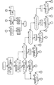
図7には、制御部60による両面モード制御の一例を示している。図7に示すように、制御部60は、両面モード制御をスタートすると始めに、外部端末等の印刷指令に含まれる記録材Pの搬送方向長さL、予定印刷枚数N、受信枚数Nrのデータを取得し(S01)、これらデータと循環枚数テーブルTとに基づいて、記録材Pの搬送方向長さLが規定長さLsのいずれかに一致するか否かを判別する(S02)。搬送方向長さLが規定長さLsのいずれかと一致する場合において(S02:YES)、予定印刷枚数Nが前記一致した規定長さLsに対応する規定循環枚数Csに1を加えた数の倍数であり(S03:YES)、且つ、受信枚数NrがCs+1以上であれば(S04:YES)、実循環枚数CをCs+1とし(S17)、入換両面モードでの印刷を実行する(S18)。
FIG. 7 shows an example of duplex mode control by the
搬送方向長さLが規定長さLsのいずれかと一致する場合、複数枚循環搬送での両面生産性は片面生産性(連続片面印刷の効率)と同程度になるから、実循環枚数Cの少ない方が、ファーストコピータイム(FCOT)や、一度に記憶可能なメモリ容量の点で有利である。ただし、予定印刷枚数NがCs+1の倍数であれば、実循環枚数CをCs+1とした方が印刷総時間を短縮できる。例えばA4縦6枚(N=6)を両面印刷する場合、5枚循環搬送と1枚循環搬送とに分けるよりも、一度に6枚循環搬送する方が素早く両面印刷を終了できる。そこで、上記の制御態様を採用したのである。なお、制御部60が実循環枚数C(=Cs+1)分のデータを受信していなければ、循環搬送時にジャムを招来するので、ステップS04の制御を採用し、受信データ不足によるジャムの発生を防止している。
When the conveyance direction length L coincides with any of the specified length Ls, the double-sided productivity in the multi-sheet circulation conveyance is almost the same as the single-sided productivity (efficiency of continuous single-sided printing). This is advantageous in terms of first copy time (FCOT) and memory capacity that can be stored at one time. However, if the scheduled number N of prints is a multiple of Cs + 1, the total printing time can be shortened by setting the actual circulation number C to Cs + 1. For example, when double-sided printing is performed on 6 sheets of A4 length (N = 6), double-sided printing can be completed more quickly by circulating and transporting 6 sheets at a time than dividing into 5 sheets of circulating transport and 1 sheet of circulating transport. Therefore, the above control mode is adopted. If the
搬送方向長さLが規定長さLsのいずれかと一致する場合において(S02:YES)、予定印刷枚数NがCs+1の倍数ではないか(S03:NO)、又は受信枚数NrがCs+1未満であれば(S04:NO)、次いで、受信枚数NrがCs以上か否かを判別する(S05)。受信枚数NrがCs未満であれば(S05:No)、制御部60が実循環枚数C(=Cs)分のデータを受信していないから、実循環枚数CをNrとし(S16)、通常両面モードでの印刷を実行する(S17)。受信枚数NrがCs以上であれば(S05:YES)、実循環枚数CをCsとし(S21)、通常両面モードでの印刷を実行する(S20)。
When the conveyance direction length L matches any of the specified lengths Ls (S02: YES), if the planned print number N is not a multiple of Cs + 1 (S03: NO), or if the received number Nr is less than Cs + 1 (S04: NO) Next, it is determined whether or not the number of received sheets Nr is equal to or greater than Cs (S05). If the number of received sheets Nr is less than Cs (S05: No), the
ステップS02において、搬送方向長さLが規定長さLsのどれとも不一致であれば(S02:NO)、次いで、記録材Pの搬送方向長さLが4枚規定サイズLs4を超え5枚規定サイズLs5未満か否かを判別する(S06)。Ls5>L>Ls4の場合は(S06:YES)、規定循環枚数Csを4枚とする(S07)。そして、受信枚数NrがCs+1(=4+1)以上ならば(S08:YES)、実循環枚数CをCs+1とし(S17)、入換両面モードでの印刷を実行する(S20)。受信枚数NrがCs+1未満であれば(S08:NO)、実循環枚数CをNrとし(S19)、通常両面モードでの印刷を実行する(S20)。 In step S02, if the transport direction length L does not match any of the specified lengths Ls (S02: NO), then the transport direction length L of the recording material P exceeds the 4-sheet specified size Ls4 and the 5-sheet specified size. It is determined whether it is less than Ls5 (S06). When Ls5> L> Ls4 (S06: YES), the specified circulation number Cs is set to 4 (S07). If the received sheet number Nr is equal to or greater than Cs + 1 (= 4 + 1) (S08: YES), the actual circulating sheet number C is set to Cs + 1 (S17), and printing in the replacement duplex mode is executed (S20). If the received sheet number Nr is less than Cs + 1 (S08: NO), the actual circulation sheet number C is set to Nr (S19), and printing in the normal duplex mode is executed (S20).
ステップS06においてLs5>L>Ls4でない場合は(S06:NO)、記録材Pの搬送方向長さLが3枚規定サイズLs3を超え4枚規定サイズLs4未満か否かを判別する(S09)。Ls4>L>Ls3の場合は(S09:YES)、規定循環枚数Csを3枚とする(S10)。そして、受信枚数NrがCs+1(=3+1)以上ならば(S11:YES)、実循環枚数CをCs+1とし(S17)、入換両面モードでの印刷を実行する(S20)。受信枚数NrがCs+1未満であれば(S11:NO)、実循環枚数CをNrとし(S19)、通常両面モードでの印刷を実行する(S20)。 If Ls5> L> Ls4 is not satisfied in step S06 (S06: NO), it is determined whether or not the conveyance direction length L of the recording material P exceeds the three-sheet specified size Ls3 and is less than the four-sheet specified size Ls4 (S09). When Ls4> L> Ls3 (S09: YES), the specified circulation number Cs is set to three (S10). If the received sheet number Nr is equal to or greater than Cs + 1 (= 3 + 1) (S11: YES), the actual circulation sheet number C is set to Cs + 1 (S17), and printing in the replacement duplex mode is executed (S20). If the received sheet number Nr is less than Cs + 1 (S11: NO), the actual circulation sheet number C is set to Nr (S19), and printing in the normal duplex mode is executed (S20).
ステップS09においてLs4>L>Ls3でない場合は(S09:NO)、記録材Pの搬送方向長さLが2枚規定サイズLs2を超え3枚規定サイズLs3未満か否かを判別する(S12)。Ls3>L>Ls2の場合は(S12:YES)、規定循環枚数Csを2枚とする(S13)。そして、受信枚数NrがCs+1(=2+1)以上ならば(S14:YES)、実循環枚数CをCs+1とし(S17)、入換両面モードでの印刷を実行する(S20)。受信枚数NrがCs+1未満であれば(S14:NO)、実循環枚数CをNrとし(S19)、通常両面モードでの印刷を実行する(S20)。 If Ls4> L> Ls3 is not satisfied in step S09 (S09: NO), it is determined whether or not the conveyance direction length L of the recording material P exceeds the two-sheet specified size Ls2 and less than the three-sheet specified size Ls3 (S12). In the case of Ls3> L> Ls2 (S12: YES), the specified circulation number Cs is set to 2 (S13). If the received sheet number Nr is equal to or greater than Cs + 1 (= 2 + 1) (S14: YES), the actual circulation sheet number C is set to Cs + 1 (S17), and printing in the replacement duplex mode is executed (S20). If the received sheet number Nr is less than Cs + 1 (S14: NO), the actual circulation sheet number C is set to Nr (S19), and printing in the normal duplex mode is executed (S20).
ステップS12においてLs3>L>Ls2でない場合は(S12:NO)、規定循環枚数Csを1枚とする(S15)。そして、受信枚数NrがCs+1(=1+1)以上ならば(S16:YES)、実循環枚数CをCs+1とし(S17)、入換両面モードでの印刷を実行する(S20)。受信枚数NrがCs+1未満であれば(S16:NO)、実循環枚数CをNrとし(S19)、通常両面モードでの印刷を実行するのである(S20)。 If Ls3> L> Ls2 is not satisfied in step S12 (S12: NO), the specified circulation number Cs is set to one (S15). If the received sheet number Nr is equal to or greater than Cs + 1 (= 1 + 1) (S16: YES), the actual circulating sheet number C is set to Cs + 1 (S17), and printing in the replacement duplex mode is executed (S20). If the received number Nr is less than Cs + 1 (S16: NO), the actual circulation number C is set to Nr (S19), and printing in the normal duplex mode is executed (S20).
なお、入換両面モード時には、反転ローラ対41にて一時待機中の記録材Pがプリンタ1外に長時間露出することになる。そこで、実施形態では、記録材Pがプリンタ1外に露出している間、制御部60に電気的に接続された報知手段としての操作パネル64(図2参照)に、一時待機中の記録材Pの除去を禁止する旨を表示(報知)する。従って、一時待機中の記録材Pを誤って引き抜かないように、ユーザに注意を喚起できる。この場合、操作パネル64の画面には、例えば図8に示すような禁止情報65が表示される。禁止情報65の表示は記録材Pがスイッチバックすれば消去され、通常画面に切り換えられる。
In the interchangeable duplex mode, the recording material P that is temporarily on standby by the reversing
また、反転ローラ対41にて記録材Pの一時待機中において、プリンタ1内でジャムが発生した場合、一時待機中の記録材P自体は無傷で再利用可能である。そこで、実施形態では、ジャムが解消するまでの間、操作パネル64に、一時待機中の記録材Pの除去を禁止する旨を表示(報知)する。従って、一時待機中の記録材Pを誤って引き抜かないように、ユーザに注意を喚起できると共に、再利用可能な記録材Pを無駄にするおそれが少なくなる。この場合、操作パネル64の画面には、例えば図9に示すような禁止情報66が表示される。禁止情報66の表示はジャムの解消によって消去され、通常画面に切り換えられる。
Further, when a jam occurs in the
さて、実施形態の制御部60は、記録材Pの搬送方向長さ又は紙種、各種印刷モード、或いはプロセス速度といった印刷動作条件が途中で変更される場合、反転ローラ対41での記録材P待機を禁止する、すなわち入換両面モードを禁止する割り込み処理も実行可能に構成されている。当該割り込み処理は両面モード制御の実行中に適宜時間間隔にて実行される。
Now, when the printing operation conditions such as the conveyance direction length or paper type of the recording material P, various printing modes, or the process speed are changed on the way, the
この場合、図10のフローチャートに示すように、例えば給紙カセット21a,21bの切換によって、次の印刷ジョブで用いられる記録材Pの紙種(普通紙、厚紙又はコート紙等)が、先の印刷ジョブで用いられた記録材Pの紙種から変更されるか(S101:YES)、若しくは、次の印刷ジョブで用いられる記録材Pの搬送方向長さLが、先の印刷ジョブで用いられた記録材Pの搬送方向長さLと異なる場合は(S102:YES)、入換両面モードでの印刷を強制的に禁止して(S107)、通常両面モードでの印刷を実行する(S108)。
In this case, as shown in the flowchart of FIG. 10, for example, by switching between the
また、次の印刷ジョブでの印刷色モードが、先の印刷ジョブでの印刷色モードと異なる場合や(S103:YES)、次の印刷ジョブでのプロセス速度が、先の印刷ジョブでのプロセス速度から変更される場合も(S104:YES)、入換両面モードでの印刷を強制的に禁止して(S107)、通常両面モードでの印刷を実行する(S108)。ここで、印刷色モードは、モノクロモードとカラーモードとの2種類に大別される。更に、メモリ容量を大幅に超える画像信号を受信して、画像データ変換等の画像処理に遅れが生じた場合や(S105:YES)、操作パネル64の停止ボタンが押された場合も(S106:YES)、入換両面モードでの印刷を強制的に禁止して(S107)、通常両面モードでの印刷を実行する(S108)。
If the print color mode in the next print job is different from the print color mode in the previous print job (S103: YES), the process speed in the next print job is the process speed in the previous print job. Even if changed from (S104: YES), printing in the replacement duplex mode is forcibly prohibited (S107), and printing in the normal duplex mode is executed (S108). Here, the print color mode is roughly divided into two types, a monochrome mode and a color mode. Further, when an image signal that greatly exceeds the memory capacity is received and image processing such as image data conversion is delayed (S105: YES), or when the stop button of the
上記のような各種印刷動作条件が途中で変更される場合は元の想定条件が変わるため、入換両面モードで印刷したとしても、個々の記録材の印刷速度が遅くなる等して、単位時間当りの印刷枚数が増えず、両面生産性を低下させる場合がある。そこで、上記の制御を採用することによって、制御の無駄を省いている。 If the various printing operation conditions as described above are changed in the middle, the original assumptions will change, so even if printing is performed in the replaceable duplex mode, the printing speed of each recording material will slow down, etc. There are cases where the number of printed sheets per page does not increase and the double-sided productivity is lowered. Therefore, waste of control is eliminated by adopting the above control.
本願発明は、前述の実施形態に限らず、様々な態様に具体化できる。例えば、画像形成装置としてプリンタを例に説明したが、これに限らず、複写機、ファクシミリ又はこれらの機能を複合的に備えた複合機等でもよい。実施形態では反転部を2つ(反転ローラ対41及び排出ローラ対42)設けているが、これに限らず、3つ以上でもよい。また、循環式の両面印刷機能としては、1枚の記録材Pの両面印刷をしてから、次の記録材Pの両面印刷をする両面交互循環方式も採用できる。その他、各部の構成は図示の実施形態に限定されるものではなく、本発明の趣旨を逸脱しない範囲で種々変更が可能である。
The present invention is not limited to the above-described embodiment, and can be embodied in various forms. For example, a printer has been described as an example of the image forming apparatus. However, the present invention is not limited to this, and a copier, a facsimile, or a multifunction machine having these functions combined may be used. In the embodiment, two reversing portions (reversing
C 実循環枚数
Cs 規定循環枚数
L 搬送方向長さ
Ls 規定長さ
N 予定印刷枚数
Nr 受信枚数
T 循環枚数テーブル
1 プリンタ
2 作像部
10 画像プロセス部
20 給送部
30 定着部
40 循環搬送部
41 反転ローラ対
42 排出ローラ対
47 経路切換ゲート
60 制御部
61 エンジン制御部
62 コントローラ部
63 ソレノイド
C Actual circulation number Cs Specified circulation number L Transport direction length Ls Specified length N Scheduled print number Nr Received number T Circulation number table 1
Claims (9)
前記反転部を複数有しており、
前記制御部は、複数枚の記録材を前記循環搬送部にて循環搬送して両面印刷する場合に、前記記録材の少なくとも1枚を前記反転部にて待機させ、前記反転部で前記記録材を待機させた状態で他の記録材を前記記録材の待機が実行されていない反転部と前記循環搬送部とで循環させ、前記記録材の待機が実行されていない反転部を前記他の記録材が通過した後に、前記記録材を待機させていた反転部における前記記録材の待機を解除し、
循環搬送される前記記録材の実循環枚数を、前記記録材の搬送方向長さに応じて定まる規定循環枚数より前記待機枚数分増加させる、
画像形成装置。 A reversing unit that reverses the recording material that has been printed on one side in the image processing unit, a circulation conveyance unit that refeeds the recording material that has been reversed, and controls the printing operation. An image forming apparatus comprising a control unit,
It has a plurality of the inversion part,
When the control unit circulates and conveys a plurality of recording materials in the circulation conveyance unit and performs double-sided printing, the control unit causes at least one of the recording materials to wait in the reversing unit, and the reversing unit causes the recording material to , The other recording material is circulated between the reversing unit in which the recording material standby is not performed and the circulation conveyance unit, and the reversing unit in which the recording material standby is not performed is performed in the other recording material. After the material has passed, the standby of the recording material in the reversing part that has been waiting for the recording material is released,
The actual number of circulating recording materials to be circulated is increased by the waiting number of sheets from a predetermined circulating number determined according to the length of the recording material in the conveyance direction.
Image forming apparatus.
請求項1に記載した画像形成装置。 The control unit is a reversing unit that waits the recording material after all of the other recording materials that can be circulated by the circulation conveyance unit pass through the reversing unit in which the recording material is not waiting. Canceling the standby of the recording material in
The image forming apparatus according to claim 1 .
請求項1又は2のうちいずれかに記載した画像形成装置。 Having two inversion parts, and waiting for the recording material in the inversion part of the inversion part far from the image processing part,
The image forming apparatus according to claim 1 .
請求項1〜3のうちいずれかに記載した画像形成装置。 The control unit switches the order of images to be printed according to the recording material discharge order accompanying the recording material standby in the reversing unit.
The image forming apparatus according to claim 1 .
請求項1〜4のうちいずれかに記載した画像形成装置。 It has two reversing parts, and one of the reversing parts also serves as a discharge part for discharging the printed recording material.
The image forming apparatus according to claim 1 .
請求項1〜5のうちいずれかに記載した画像形成装置。 When the number of received sheets included in the print command is less than (the specified circulating sheet number + 1), the control unit sets the actual circulating sheet number as the specified circulating sheet number without waiting for the recording material in the reversing unit.
The image forming apparatus according to claim 1 .
請求項1〜6のうちいずれかに記載した画像形成装置。 When the length of the recording material in the conveyance direction is a specified length and the expected number of printed sheets is a multiple of (the specified circulation number + 1), the control unit waits for the recording material in the reversing unit and performs the actual circulation. Let the number of sheets be (the specified circulation number + 1),
The image forming apparatus according to claim 1 .
請求項1〜7のうちいずれかに記載した画像形成装置。 When the printing operation condition such as the length or the paper type of the recording material, the various printing modes, or the process speed is changed in the middle, the control unit prohibits the recording material standby in the reversing unit,
Image forming apparatus according to any one of claims 1 to 7.
請求項1〜8のうちいずれかに記載した画像形成装置。 When the recording material on standby in the reversing unit is exposed outside the apparatus, the control unit notifies that the removal of the recording material on standby is prohibited by a notification unit connected thereto.
The image forming apparatus according to claim 1 .
Priority Applications (2)
| Application Number | Priority Date | Filing Date | Title |
|---|---|---|---|
| JP2010284955A JP5522401B2 (en) | 2010-12-21 | 2010-12-21 | Image forming apparatus |
| US13/328,740 US9075366B2 (en) | 2010-12-21 | 2011-12-16 | Image forming apparatus |
Applications Claiming Priority (1)
| Application Number | Priority Date | Filing Date | Title |
|---|---|---|---|
| JP2010284955A JP5522401B2 (en) | 2010-12-21 | 2010-12-21 | Image forming apparatus |
Publications (2)
| Publication Number | Publication Date |
|---|---|
| JP2012131609A JP2012131609A (en) | 2012-07-12 |
| JP5522401B2 true JP5522401B2 (en) | 2014-06-18 |
Family
ID=46234631
Family Applications (1)
| Application Number | Title | Priority Date | Filing Date |
|---|---|---|---|
| JP2010284955A Active JP5522401B2 (en) | 2010-12-21 | 2010-12-21 | Image forming apparatus |
Country Status (2)
| Country | Link |
|---|---|
| US (1) | US9075366B2 (en) |
| JP (1) | JP5522401B2 (en) |
Families Citing this family (9)
| Publication number | Priority date | Publication date | Assignee | Title |
|---|---|---|---|---|
| JP2014021268A (en) * | 2012-07-18 | 2014-02-03 | Canon Inc | Image forming apparatus |
| JP6097535B2 (en) * | 2012-11-29 | 2017-03-15 | キヤノン株式会社 | Image forming apparatus, control method therefor, and program |
| JP2015084172A (en) * | 2013-10-25 | 2015-04-30 | キヤノン株式会社 | Information processor and program, and control method |
| US9551972B2 (en) * | 2014-12-19 | 2017-01-24 | Canon Kabushiki Kaisha | Image forming apparatus |
| JP6494497B2 (en) * | 2014-12-19 | 2019-04-03 | キヤノン株式会社 | Image forming apparatus |
| JP6156439B2 (en) * | 2015-05-11 | 2017-07-05 | コニカミノルタ株式会社 | Sheet conveying apparatus, and image forming apparatus and system including the same |
| JP6639248B2 (en) * | 2016-01-22 | 2020-02-05 | キヤノン株式会社 | Image forming apparatus and sheet processing apparatus |
| JP6668977B2 (en) * | 2016-07-01 | 2020-03-18 | 富士ゼロックス株式会社 | Image forming device |
| JP6836739B2 (en) * | 2016-09-16 | 2021-03-03 | 株式会社リコー | Image forming device |
Family Cites Families (13)
| Publication number | Priority date | Publication date | Assignee | Title |
|---|---|---|---|---|
| JPH10157212A (en) * | 1996-11-29 | 1998-06-16 | Casio Electron Mfg Co Ltd | Perfecting press |
| JP3945093B2 (en) * | 1999-10-19 | 2007-07-18 | セイコーエプソン株式会社 | Image forming apparatus |
| JP2001206644A (en) * | 2000-01-21 | 2001-07-31 | Canon Inc | Re-feeding device and image forming device |
| JP3943842B2 (en) * | 2000-03-10 | 2007-07-11 | 株式会社リコー | Double-sided image recording device |
| JP3768785B2 (en) | 2000-07-19 | 2006-04-19 | キヤノン株式会社 | Image forming apparatus and storage medium |
| JP2002323800A (en) | 2001-04-25 | 2002-11-08 | Konica Corp | Device and method for processing sheet, and image forming device |
| JP4368766B2 (en) * | 2004-08-31 | 2009-11-18 | 京セラミタ株式会社 | Image forming apparatus |
| US7546056B2 (en) * | 2004-12-22 | 2009-06-09 | Canon Kabushiki Kaisha | Printing apparatus and method performing either automatic or manual duplex printing based on copy media attributes |
| JP4492380B2 (en) * | 2005-02-04 | 2010-06-30 | 富士ゼロックス株式会社 | Recording device |
| US7570897B2 (en) * | 2005-04-08 | 2009-08-04 | Canon Kabushiki Kaisha | Duplex image forming apparatus and method with control for ejecting different size recording sheet |
| JP2007225769A (en) * | 2006-02-22 | 2007-09-06 | Konica Minolta Business Technologies Inc | Image forming apparatus |
| KR20080070177A (en) * | 2007-01-25 | 2008-07-30 | 삼성전자주식회사 | Duplex image forming apparatus and duplex image forming method of thereof |
| JP4640478B2 (en) * | 2008-09-26 | 2011-03-02 | ブラザー工業株式会社 | Image recording device |
-
2010
- 2010-12-21 JP JP2010284955A patent/JP5522401B2/en active Active
-
2011
- 2011-12-16 US US13/328,740 patent/US9075366B2/en not_active Expired - Fee Related
Also Published As
| Publication number | Publication date |
|---|---|
| US20120155943A1 (en) | 2012-06-21 |
| US9075366B2 (en) | 2015-07-07 |
| JP2012131609A (en) | 2012-07-12 |
Similar Documents
| Publication | Publication Date | Title |
|---|---|---|
| JP5522401B2 (en) | Image forming apparatus | |
| JP6938287B2 (en) | Image forming device | |
| JP2016081007A (en) | Conveyance device, image forming apparatus, and conveyance control method | |
| JP6642248B2 (en) | Image forming apparatus, image forming system, and notification method | |
| JP6093732B2 (en) | Image forming apparatus | |
| JP2012047944A (en) | Image formation system | |
| JP6180991B2 (en) | Image forming apparatus | |
| JP4720628B2 (en) | Paper feeder | |
| JP5262480B2 (en) | Image forming method and image forming apparatus | |
| JP2012098654A (en) | Multiple image forming apparatus | |
| JP2000321953A (en) | Image forming device | |
| JP2013003355A (en) | Image forming apparatus | |
| JP5120470B2 (en) | Paper feeding device and image forming system | |
| JP5332154B2 (en) | Image forming apparatus | |
| JP2011197321A (en) | Image forming system | |
| JP2006221217A (en) | Apparatus system, and image forming apparatus system | |
| JP4709030B2 (en) | Image forming apparatus | |
| JP2006178068A (en) | Device system and image forming apparatus system | |
| JP5790935B2 (en) | Image forming apparatus | |
| JP2002202639A (en) | Image forming device and image forming method | |
| JP6447072B2 (en) | Image forming apparatus and image forming system | |
| JP5748053B2 (en) | Image forming apparatus | |
| JP6036269B2 (en) | Image forming apparatus and program | |
| JP2010180044A (en) | Recording medium carrying processing unit, and image forming device | |
| JP2022068809A (en) | Image forming device |
Legal Events
| Date | Code | Title | Description |
|---|---|---|---|
| A621 | Written request for application examination |
Free format text: JAPANESE INTERMEDIATE CODE: A621 Effective date: 20121018 |
|
| A977 | Report on retrieval |
Free format text: JAPANESE INTERMEDIATE CODE: A971007 Effective date: 20130124 |
|
| A131 | Notification of reasons for refusal |
Free format text: JAPANESE INTERMEDIATE CODE: A131 Effective date: 20130130 |
|
| A521 | Written amendment |
Free format text: JAPANESE INTERMEDIATE CODE: A523 Effective date: 20130329 |
|
| A521 | Written amendment |
Free format text: JAPANESE INTERMEDIATE CODE: A523 Effective date: 20130402 |
|
| A711 | Notification of change in applicant |
Free format text: JAPANESE INTERMEDIATE CODE: A712 Effective date: 20130417 |
|
| A02 | Decision of refusal |
Free format text: JAPANESE INTERMEDIATE CODE: A02 Effective date: 20131106 |
|
| A521 | Written amendment |
Free format text: JAPANESE INTERMEDIATE CODE: A523 Effective date: 20140205 |
|
| A911 | Transfer of reconsideration by examiner before appeal (zenchi) |
Free format text: JAPANESE INTERMEDIATE CODE: A911 Effective date: 20140218 |
|
| TRDD | Decision of grant or rejection written | ||
| A01 | Written decision to grant a patent or to grant a registration (utility model) |
Free format text: JAPANESE INTERMEDIATE CODE: A01 Effective date: 20140312 |
|
| A61 | First payment of annual fees (during grant procedure) |
Free format text: JAPANESE INTERMEDIATE CODE: A61 Effective date: 20140325 |
|
| R150 | Certificate of patent (=grant) or registration of utility model |
Ref document number: 5522401 Country of ref document: JP Free format text: JAPANESE INTERMEDIATE CODE: R150 |