JP5511548B2 - Image forming apparatus - Google Patents
Image forming apparatus Download PDFInfo
- Publication number
- JP5511548B2 JP5511548B2 JP2010150243A JP2010150243A JP5511548B2 JP 5511548 B2 JP5511548 B2 JP 5511548B2 JP 2010150243 A JP2010150243 A JP 2010150243A JP 2010150243 A JP2010150243 A JP 2010150243A JP 5511548 B2 JP5511548 B2 JP 5511548B2
- Authority
- JP
- Japan
- Prior art keywords
- image forming
- unit
- sheet
- image
- sided
- Prior art date
- Legal status (The legal status is an assumption and is not a legal conclusion. Google has not performed a legal analysis and makes no representation as to the accuracy of the status listed.)
- Expired - Fee Related
Links
Images


Classifications
-
- G—PHYSICS
- G03—PHOTOGRAPHY; CINEMATOGRAPHY; ANALOGOUS TECHNIQUES USING WAVES OTHER THAN OPTICAL WAVES; ELECTROGRAPHY; HOLOGRAPHY
- G03G—ELECTROGRAPHY; ELECTROPHOTOGRAPHY; MAGNETOGRAPHY
- G03G15/00—Apparatus for electrographic processes using a charge pattern
- G03G15/22—Apparatus for electrographic processes using a charge pattern involving the combination of more than one step according to groups G03G13/02 - G03G13/20
- G03G15/23—Apparatus for electrographic processes using a charge pattern involving the combination of more than one step according to groups G03G13/02 - G03G13/20 specially adapted for copying both sides of an original or for copying on both sides of a recording or image-receiving material
- G03G15/231—Arrangements for copying on both sides of a recording or image-receiving material
- G03G15/238—Arrangements for copying on both sides of a recording or image-receiving material using more than one reusable electrographic recording member, e.g. single pass duplex copiers
-
- B—PERFORMING OPERATIONS; TRANSPORTING
- B41—PRINTING; LINING MACHINES; TYPEWRITERS; STAMPS
- B41J—TYPEWRITERS; SELECTIVE PRINTING MECHANISMS, i.e. MECHANISMS PRINTING OTHERWISE THAN FROM A FORME; CORRECTION OF TYPOGRAPHICAL ERRORS
- B41J13/00—Devices or arrangements of selective printing mechanisms, e.g. ink-jet printers or thermal printers, specially adapted for supporting or handling copy material in short lengths, e.g. sheets
- B41J13/009—Diverting sheets at a section where at least two sheet conveying paths converge, e.g. by a movable switching guide that blocks access to one conveying path and guides the sheet to another path, e.g. when a sheet conveying direction is reversed after printing on the front of the sheet has been finished and the sheet is guided to a sheet turning path for printing on the back
-
- B—PERFORMING OPERATIONS; TRANSPORTING
- B41—PRINTING; LINING MACHINES; TYPEWRITERS; STAMPS
- B41J—TYPEWRITERS; SELECTIVE PRINTING MECHANISMS, i.e. MECHANISMS PRINTING OTHERWISE THAN FROM A FORME; CORRECTION OF TYPOGRAPHICAL ERRORS
- B41J3/00—Typewriters or selective printing or marking mechanisms characterised by the purpose for which they are constructed
- B41J3/60—Typewriters or selective printing or marking mechanisms characterised by the purpose for which they are constructed for printing on both faces of the printing material
-
- G—PHYSICS
- G03—PHOTOGRAPHY; CINEMATOGRAPHY; ANALOGOUS TECHNIQUES USING WAVES OTHER THAN OPTICAL WAVES; ELECTROGRAPHY; HOLOGRAPHY
- G03G—ELECTROGRAPHY; ELECTROPHOTOGRAPHY; MAGNETOGRAPHY
- G03G2215/00—Apparatus for electrophotographic processes
- G03G2215/00016—Special arrangement of entire apparatus
- G03G2215/00021—Plural substantially independent image forming units in cooperation, e.g. for duplex, colour or high-speed simplex
Landscapes
- Physics & Mathematics (AREA)
- General Physics & Mathematics (AREA)
- Accessory Devices And Overall Control Thereof (AREA)
- Control Or Security For Electrophotography (AREA)
- Dot-Matrix Printers And Others (AREA)
Description
本発明は、画像形成装置に関し、特には複数の画像形成部を有する画像形成装置に関する。 The present invention relates to an image forming apparatus, and more particularly to an image forming apparatus having a plurality of image forming units.
従来、複数の画像形成装置(例えば、2台)を連結して複数の画画像形成部を備える画像形成装置が知られている。このような画像形成装置は、複数の画像形成部で連続的に画像を形成させることにより、両面画像形成処理等における生産性の向上を図っている(特許文献1参照)。 2. Description of the Related Art Conventionally, an image forming apparatus that includes a plurality of image forming units by connecting a plurality of image forming apparatuses (for example, two) is known. In such an image forming apparatus, productivity is improved in double-sided image forming processing or the like by continuously forming images with a plurality of image forming units (see Patent Document 1).
例えば、特許文献1に開示の画像形成装置は、第1画像形成部で第1面の画像形成を行った後、第2画像形成部で第2面の画像形成を行うことにより、両面画像形成処理における高い生産性を維持している。また、特許文献1に開示の画像形成装置は、連結される画像形成装置ごとに排紙処理装置を設ける必要がないため、個々に画像形成装置を配置する場合に比べて省スペース化を図ることができる。
For example, the image forming apparatus disclosed in
しかしながら、特許文献1に示す従来の画像形成装置は、片面画像形成処理と両面画像形成処理の混合処理における片面画像形成処理を行う場合に、第2画像形成部においては画像形成を行うことなくシートを通過させていた。すなわち、第1給紙部からシートを給紙して第1画像形成部で第1面の画像形成を行った後、中間搬送路を介して第2画像形成部に搬送し、第2画像形成部では画像形成を行うことなくシートを通過させて排紙していた。そしてこれは、画像形成部の寿命を低下させるおそれがあった。
However, the conventional image forming apparatus disclosed in
そこで、本発明は、画像形成処理における高い生産性を維持した状態で、画像形成部の耐久寿命の低下を抑制可能な画像形成装置を提供することを目的とする。 SUMMARY An advantage of some aspects of the invention is that it provides an image forming apparatus capable of suppressing a decrease in durability of an image forming unit while maintaining high productivity in image forming processing.
本発明は、第1画像形成部と、前記第1画像形成部の下流側に設けられる第2画像形成部と、前記第1画像形成部で画像形成されたシートを前記第2画像形成部に搬送する中間搬送部と、前記中間搬送部から分岐し、前記第1画像形成部によって画像が形成されたシートを排出する排出部と、前記第1画像形成部及び前記第2画像形成部における画像形成処理の制御を行う画像形成制御部と、を備え、前記画像形成制御部は、片面画像形成処理及び両面画像形成処理の2つの処理を行う混合処理において、片面画像形成処理の時は、前記第2画像形成部によってシートの第1面に画像を形成させ、両面画像形成処理の時は、前記第1画像形成部によってシートの第1面の画像形成を行った後、前記中間搬送部を介して前記第2画像形成部にシートを搬送して前記第2画像形成部によってシートの第2面に画像を形成させ、前記混合処理を行っているときに、前記混合処理とは異なる片面画像形成処理の実行要求があった場合には、前記第2画像形成部によって前記混合処理に係る片面画像形成を行う間、前記第1画像形成部によって、前記混合処理の混合ジョブとは異なる片面画像形成処理の前記実行要求に係る片面画像形成を行い、前記混合処理とは異なる片面画像形成処理が行われたシートを前記排出部から排出させることを特徴とする。 The present invention includes a first image forming unit, the second image forming unit provided downstream of the first image forming unit, before Symbol said second image forming unit a sheet on which an image is formed by the first image forming unit An intermediate conveyance unit that conveys the sheet to the sheet, a discharge unit that branches from the intermediate conveyance unit and discharges a sheet on which an image has been formed by the first image forming unit, and the first image forming unit and the second image forming unit. comprising an image forming control unit for controlling the image forming processing, wherein the image forming control unit, in the mixing process for two processes one-side image forming process and the double-sided image forming process, when the one-side image forming process , before SL to form an image on a first side of the sheet by the second image forming unit, when the double-sided image forming process, after the image-shaped configuration of the first side of the sheet by the front Symbol first image forming unit, sheet to said second image forming unit through the intermediate conveyance unit And conveying the door by the second image forming unit to form an image on the second side of the sheet, while performing the mixing process if, there is a request for execution of different single-sided image forming process and the mixing process The one-side image relating to the execution request for the one-sided image forming process different from the mixed job of the mixing process by the first image forming unit while the one-sided image formation related to the mixing process is performed by the second image forming unit. performs image formation, a sheet on one side image formation processing different from the mixing process is carried out you characterized thereby discharged from the discharge portion.
本発明は、片面及び両面の混合処理を行う場合に、片面画像形成処理時は、第2画像形成部で画像を形成することで、画像形成処理における高い生産性を維持した状態で、画像形成部の耐久寿命の低下を抑制することができる。 In the present invention, when single-sided and double-sided mixing processing is performed, during single-sided image forming processing, image formation is performed while maintaining high productivity in image forming processing by forming an image in the second image forming unit. It is possible to suppress a decrease in the durable life of the part.
以下、本発明の実施形態に係る画像形成装置について、図面を参照しながら説明する。本発明の実施形態に係る画像形成装置は、複写機、プリンタ、ファクシミリ及びこれら複合機器等、シートの両面に印刷可能な両面印刷機能を有する2台の画像形成装置を連結させたものである。以下の実施形態においては、画像形成装置として、2台の高速モノクロプリンタを連結させた画像形成装置を用いて説明する。 Hereinafter, an image forming apparatus according to an embodiment of the present invention will be described with reference to the drawings. An image forming apparatus according to an embodiment of the present invention is a combination of two image forming apparatuses having a duplex printing function capable of printing on both sides of a sheet, such as a copying machine, a printer, a facsimile, and a composite device thereof. In the following embodiments, an image forming apparatus in which two high-speed monochrome printers are connected will be described as an image forming apparatus.
<第1実施形態>
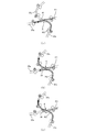
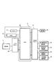
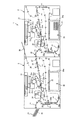
本発明の第1実施形態に係る画像形成装置1について、図1から図10を参照しながら説明する。まず、第1実施形態に係る画像形成装置1の全体構造について、図1から図3を参照しながら説明する。図1は、本発明の第1実施形態に係る画像形成装置1の全体構造を模式的に示す断面図である。図2(a)は、第1位置にある切替部材39を示す図である。図2(b)は、第2位置にある切替部材39を示す図である。図2(c)は、第3位置にある切替部材39を示す図である。図3は、第1実施形態に係る画像形成装置1の画像形成制御部4を示すブロック図である。
<First Embodiment>
An
図1及び図2に示すように、第1実施形態に係る画像形成装置1は、第1画像形成装置2と、第1画像形成装置2の下流側に設けられた第2画像形成装置3と、第1画像形成装置2及び第2画像形成装置3を制御する画像形成制御部4と、を備える。第1画像形成装置2と第2画像形成装置3とは、第1画像形成装置2で画像が形成されたシートを第2画像形成装置3に引渡し可能に連結されている。
As shown in FIGS. 1 and 2, the
第1画像形成装置2は、シートP1を給紙する第1給紙部20と、第1給紙部20から給紙されたシートP1に画像を形成する第1画像形成部21と、シートP1への転写を行う転写部22と、を備える。また、第1画像形成装置2は、定着前搬送ベルトユニット23と、画像を定着させる定着部24と、シートP1の裏表を反転させる反転ユニット25と、画像が形成されたシートP1を第2画像形成装置3に引渡すシート排紙部26と、を備える。なお、第1給紙部20、第1画像形成部21、転写部22等は、所定の搬送パスにより接続されているが、ここではその説明は省略する。
The first
第1給紙部20は、シートP1を収容する給紙デッキ20aを備え、給紙デッキ20aからシートP1を給紙する。第1画像形成部21は、所定の画像情報に基づいて第1給紙部20から給紙されたシートP1に画像を形成する。第1画像形成部21は、感光体ドラム21aと、コロナ帯電部21bと、露光部21cと、現像部21dと、一次転写ローラ21eと、トナー回収部21fと、を備える。感光体ドラム21aは、帯電極性が負極性の感光層を表面に形成した金属円筒で構成され、所定の方向(図1に示す矢印R1方向)に回転する。コロナ帯電部21bは、像担持体である感光体ドラム21aのドラム表面を均一に帯電する。露光部21cは、画像情報に基づいてレーザービームを照射し感光体ドラム21a上に静電潜像を形成する。現像部21dは、静電潜像にトナーを付着させてトナー像として顕像化する。一次転写ローラ21eは、一次転写部T1で、感光体ドラム21a上のトナー像を後述の中間転写ベルト22aに転写させる。トナー回収部21fは、転写後の感光体ドラム21aの表面に残ったトナーを除去する。
The first
転写部22は、トナー像が転写される中間転写ベルト22aを備え、中間転写ベルト22aは、二次転写部T2でシートP1にトナー像を転写する。定着前搬送ベルトユニット23は、シートP1を二次転写部T2から定着部24に搬送する。定着部24は、加圧ローラ24a及び定着ローラ24bを備え、加熱加圧により転写されたトナー像をシートP1に定着させる。
The
シート排紙部26は、定着部24でトナー像が定着されたシートP1を第2画像形成装置3に受け渡す中間搬送部を構成する。反転ユニット25は、シート排紙部26から分岐した第1反転パス25aと、正回転及び逆回転可能な反転ローラ対25bと、シート排紙部26に接続される第2反転パス25cと、第1画像形成部21に接続される第3反転パス25dと、を備える。反転ユニット25は、定着部24でトナー像が定着されたシートP1の表裏を反転させてシート排紙部26又は第1画像形成部21にシートP1を搬送するためのものである。
The
第2画像形成装置3は、シートP2を給紙する第2給紙部30と、第2給紙部30から給紙されたシートP2に画像を形成する第2画像形成部31と、シートP2への転写を行う転写部32と、を備える。また、第2画像形成装置3は、定着前搬送ベルトユニット33と、画像を定着させる定着部34と、シートP2の表裏を反転させる反転ユニット35と、画像が形成されたシートP2を排出するシート排紙部36と、を備える。また、第2画像形成装置3は、シート受取部37と、排出部としての中間排紙トレイ38と、を備える。なお、第2給紙部30、第2画像形成部31、転写部32等は、第1画像形成装置2と同様に、所定の搬送路により接続されているが、ここではその説明は省略する。
The second image forming apparatus 3 includes a second
第2給紙部30は、シートP2を収容する給紙デッキ30aを備え、給紙デッキ30aからシートP2を給紙する。第2画像形成部31は、所定の画像情報に基づいて第2給紙部30から給紙されたシートP2に画像を形成する。第2画像形成部31は、感光体ドラム31aと、コロナ帯電部31bと、露光部31cと、現像部31dと、一次転写ローラ31eと、トナー回収部31fと、を備える。感光体ドラム31aは、帯電極性が負極性の感光層を表面に形成した金属円筒で構成され、所定の方向(図1に示す矢印R2方向)に回転する。コロナ帯電部31bは、像担持体である感光体ドラム31aのドラム表面を均一に帯電する。露光部31cは、画像情報に基づいてレーザービームを照射し感光体ドラム31a上に静電潜像を形成する。現像部31dは、静電潜像にトナーを付着させてトナー像として顕像化する。一次転写ローラ31eは、一次転写部T3で、感光体ドラム31a上のトナー像を後述の中間転写ベルト32aに転写させる。トナー回収部31fは、転写後の感光体ドラム31aの表面に残ったトナーを除去する。
The second
転写部32は、トナー像が転写される中間転写ベルト32aを備え、中間転写ベルト32aは、二次転写部T4でシートP2にトナー像を転写する。定着前搬送ベルトユニット33は、シートP2を二次転写部T4から定着部34に搬送する。定着部34は、加圧ローラ34a及び定着ローラ34bを備え、加熱加圧により転写されたトナー像をシートP2に定着させる。
The
シート排紙部36は、定着部34でトナー像が定着され、両面に画像が形成されたシートP1又は片面に画像が形成されたシートP2を排紙する。反転ユニット35は、シート排紙部36から分岐した第1反転パス35aと、正回転及び逆回転可能な反転ローラ対35bと、シート排紙部36に接続される第2反転パス35cと、第2画像形成部31に接続される第3反転パス35dと、を備える。反転ユニット35は、定着部34でトナー像が定着されたシートP1又はシートP2の表裏を反転させてシート排紙部26又は第2画像形成部31にシートP1を搬送するためのものである。
The
シート受取部37は、シート排紙部26と連結されており、第1画像形成部21で画像が形成されたシートP1を受け取り、第2画像形成部31に搬送する中間搬送部を構成する。シート受取部37は、シート排紙部26と連結された搬送路37aと、第2給紙部30に収容されたシートP2を給紙するための給紙路37bと、搬送路37aから分岐して中間排紙トレイ38に接続される排紙路37cと、切替部材39と、を備える。
The
図2(a)から図2(c)に示すように、搬送路37a及び排紙路37cは、搬送路37aに設けられる分岐点Aで搬送路37aに接続されており、分岐点Aには、切替部材39が配置されている。切替部材39は、図2(a)に示す第1位置と、図2(b)に示す第2位置と、図2(c)に示す第3位置とに回動可能に設けられており、分岐点Aでシートの搬送方向を規定する。
As shown in FIGS. 2A to 2C, the
具体的には、切替部材39は、第1位置に位置することにより、排紙路37cを遮断してシート排紙部26から搬送されるシートP1及び第2給紙部30から給紙されるシートP2を搬送路37aに搬送させる。また、切替部材39は、第2位置に位置することにより、シート排紙部26から搬送されるシートP1を排紙路37cに搬送させると共に、第2給紙部30から給紙されるシートP2を搬送路37aに搬送させる。更に、切替部材39は、第3位置に位置することにより、分岐点Aにおける搬送路37aを遮断してシート排紙部26から搬送されるシートP1及び第2給紙部30から給紙されるシートP2を排紙路37cに搬送させる。なお、切替部材39は、パルスモータ(図示せず)に駆動され、第1位置、第2位置及び第3位置のいずれかに位置するように後述の画像形成制御部4により制御される。
Specifically, the switching
中間排紙トレイ38は、排紙路37cに接続されており、第1画像形成部21で画像が形成されたシートP1を収容する。
The intermediate
図3に示すように、画像形成制御部4は、CPU40と、制御プログラムを格納するROM41と、制御データを一時的に保持するための領域や制御に伴う演算の作業領域として用いられるRAM42と、を備える。CPUは、ROM41に格納された制御プログラム及び操作部5から入力ドライバ50を介して入力された設定に従い、入出力ドライバ51を介して第1画像形成駆動部52、第1搬送駆動部53、第2画像形成駆動部54及び第2搬送駆動部55を制御する。操作部から入力された設定等は、表示部56に表示される。
As shown in FIG. 3, the image formation control unit 4 includes a CPU 40, a
なお、第1画像形成駆動部52とは、第1画像形成部21で画像を形成するための各部の総称であり、第1搬送駆動部53とは、第1給紙部20から給紙を行うための各部の総称をいう。また、第2画像形成駆動部54とは、第2画像形成部31で画像を形成するための各部の総称であり、第2搬送駆動部55とは、第2給紙部30から給紙を行うための各部の総称をいう。
The first image forming drive unit 52 is a general term for each unit for forming an image in the first
次に、第1実施形態に係る画像形成装置1の画像形成制御部4における制御動作について、図4から図10を参照しながら説明する。まず、画像形成制御部4における主制御動作について図4を参照しながら説明する。図4は、第1実施形態に係る画像形成装置1の画像形成制御部4における制御動作を示すフローチャートである。
Next, a control operation in the image forming control unit 4 of the
図4に示すように、ユーザが操作部5を操作してユーザからの実行要求(ジョブ)があると、画像形成制御部4は、まず、ユーザにより入力された実行要求(ジョブ)を認識する(ステップST1)。ユーザからの実行要求(ジョブ)を認識すると、画像形成制御部4は、実行要求(ジョブ)が両面画像印刷と片面画像印刷の混合であるか否かを判断する(ステップST2)。実行要求(ジョブ)が両面画像印刷と片面画像印刷の混合である場合には、ステップST3に進み、画像形成制御部4は、両面画像印刷と片面画像印刷の混合処理である第3画像形成処理を行う。一方、実行要求(ジョブ)が両面画像印刷と片面画像印刷の混合でない場合には、ステップST4に進む。
As shown in FIG. 4, when the user operates the
ステップST4においては、画像形成制御部4は、実行要求(ジョブ)が両面画像印刷であるか否かを判断する。実行要求(ジョブ)が両面印刷である場合には、ステップST5に進み、画像形成制御部4は、両面画像形成処理である第1画像形成処理を行う。一方、実行要求(ジョブ)が両面印刷でない場合には、画像形成制御部4は、ステップST7に進み、片面画像形成処理である第2画像形成処理を行う。第1画像形成処理、第2画像形成処理又は第3画像形成処理が終了すると、画像形成制御部4は、ユーザからの実行要求(ジョブ)が終了したか否かを判断する(ステップST8)。実行要求(ジョブ)が終了している場合には、制御動作を終了し、実行要求(ジョブ)が終了していない場合にはステップST1に戻り、上述を繰り返す。
In step ST4, the image formation control unit 4 determines whether or not the execution request (job) is double-sided image printing. If the execution request (job) is double-sided printing, the process proceeds to step ST5, and the image formation control unit 4 performs a first image formation process that is a double-sided image formation process. On the other hand, if the execution request (job) is not double-sided printing, the image forming control unit 4 proceeds to step ST 7, performs the second image forming process is a single-sided image forming process. When the first image forming process, the second image forming process, or the third image forming process is finished, the image forming control unit 4 determines whether or not the execution request (job) from the user is finished (step ST 8 ). . When the execution request (job) is completed, and ends the control operation returns to step
次に、両面画像形成処理である第1画像形成処理について、図5及び図6を参照しながら、シートP1の流れに沿って説明する。図5は、第1実施形態に係る画像形成制御部4における第1画像形成処理を示すフローチャートである。図6は、第1実施形態に係る第1画像形成処理におけるシートの流れを示す図である。 Next, the first image forming process, which is a double-sided image forming process, will be described along the flow of the sheet P1 with reference to FIGS. FIG. 5 is a flowchart showing a first image forming process in the image forming control unit 4 according to the first embodiment. FIG. 6 is a diagram illustrating a sheet flow in the first image forming process according to the first embodiment.
図5に示すように、第1画像形成処理が開始されると、画像形成制御部4は、切替部材39を第1位置(図2(a)参照)に位置させる(ステップST11)。次に、画像形成制御部4は、第1搬送駆動部53を駆動してシートP1の給紙を開始する(ステップST12)。具体的には、図6に示すように、給紙デッキ20aからシートP1を1枚ずつ引き出すと共にローラ対で搬送し、レジストローラ(図示せず)により二次転写部T2の手前でシートP1を待機させる。
As shown in FIG. 5, when the first image forming process is started, the image forming control unit 4 positions the switching
次に、画像形成制御部4は、第1画像形成駆動部52を駆動して、シートP1の第1面(片面)に画像形成を行う(ステップST13)。具体的には、コロナ帯電部21bで感光体ドラム21aのドラム表面を均一に帯電した後、露光部21cで画像情報に基づいてレーザービームを照射し、感光体ドラム21a上に静電潜像を形成する。その後、現像部21dで静電潜像にトナーを付着させてトナー像として顕像化し、一次転写ローラ21eにより感光体ドラム21a上のトナー像を中間転写ベルト22aに一次転写させる。
Next, the image formation control unit 4 drives the first image formation driving unit 52 to form an image on the first surface (one surface) of the sheet P1 (step ST13). Specifically, after the drum surface of the
ここで、レジストローラにより待機させられているシートP1は、所定のタイミングで二次転写部T2に送り出され、中間転写ベルト22aに一次転写されたトナー像がシートP1に二次転写される。トナー像が二次転写されたシートP1は、定着前搬送ベルトユニット23により二次転写部T2から定着部24に搬送され、加圧ローラ24a及び定着ローラ24bの加熱加圧により転写されたトナー像が定着される。
Here, the sheet P1 kept on standby by the registration roller is sent to the secondary transfer portion T2 at a predetermined timing, and the toner image primarily transferred to the
第1面にトナー像が形成されたシートP1は、第1反転パス25aに搬送された後、反転ローラ対25bを逆回転させることにより表裏が反転される。表裏が反転されたシートP1は、第2反転パス25cを介してシート排紙部26に搬送される。シート排紙部26に搬送されたシートP1は、シート受取部37で受け取られ、切替部材39により第2画像形成部31に搬送される。
After the sheet P1 having the toner image formed on the first surface is conveyed to the first reversing
シート受取部37及び切替部材39を介して第2画像形成装置3にシートP1が搬送されると、画像形成制御部4は、レジストローラ(図示せず)により二次転写部T4の手前でシートP1を待機させる。
When the sheet P1 is conveyed to the second image forming apparatus 3 via the
次に、画像形成制御部4は、第2画像形成駆動部54を駆動して、シートP1の第2面に画像形成を行う(ステップST14)。具体的には、コロナ帯電部31bで感光体ドラム31aのドラム表面を均一に帯電した後、露光部31cで画像情報に基づいてレーザービームを照射し感光体ドラム31a上に静電潜像を形成する。その後、現像部31dで静電潜像にトナーを付着させてトナー像として顕像化し、一次転写ローラ31eにより感光体ドラム31a上のトナー像を中間転写ベルト32aに一次転写させる。
Next, the image formation control unit 4 drives the second image formation drive unit 54 to form an image on the second surface of the sheet P1 (step ST14). Specifically, after the drum surface of the
ここで、レジストローラにより待機させられているシートP1は、所定のタイミングで二次転写部T4に送り出され、中間転写ベルト32aに一次転写されたトナー像が二次転写部T4でシートP1の第2面に二次転写される。トナー像が二次転写されたシートP1は、定着前搬送ベルトユニット33により二次転写部T4から定着部34に搬送され、加圧ローラ34a及び定着ローラ34bの加熱加圧により転写されたトナー像が定着される。
Here, the sheet P1 kept on standby by the registration rollers is sent to the secondary transfer portion T4 at a predetermined timing, and the toner image primarily transferred to the
第2面にトナー像が形成されたシートP1は、第1反転パス35aに搬送された後、反転ローラ対35bを逆回転させることにより表裏を反転され(第1面を表面として)、第2反転パス35cを介してシート排紙部36に積載される。次に、画像形成制御部4は、すべての実行要求(ジョブ)に係る両面印刷が完了したか否か(最終ページまで完了したか否か)を判断する(ステップST15)。終了していないと判断した場合には、ステップST11に戻り、終了していると判断した場合には、第1画像形成処理を終了させて、画像形成制御部4の主制御動作に戻る。
After the sheet P1 having the toner image formed on the second surface is conveyed to the first reversing
次に、片面画像形成処理である第2画像形成処理について、図7及び図8を参照しながら、シートP1の流れに沿って説明する。図7は、第1実施形態に係る画像形成制御部4における第2画像形成処理を示すフローチャートである。図8は、第1実施形態に係る第2画像形成処理におけるシートの流れを示す図である。 Next, the second image forming process, which is a single-sided image forming process, will be described along the flow of the sheet P1 with reference to FIGS. FIG. 7 is a flowchart showing a second image forming process in the image forming control unit 4 according to the first embodiment. FIG. 8 is a diagram illustrating a sheet flow in the second image forming process according to the first embodiment.
第2画像形成処理は、片面画像形成処理であるため、1回の画像形成により画像形成処理は終了する。そのため、片面画像形成処理の場合は、第1画像形成装置2と、第2画像形成装置3とをそれぞれ独立の画像形成装置として稼働させることができる。本実施形態においては、画像形成処理を行うシート束のページ前半部と、ページ後半部とに分割し、ページ前半部を第1画像形成装置2で片面画像形成を行い、ページ後半部を第2画像形成装置3で片面画像形成を行うように構成した。以下、具体的に説明する。なお、第1画像形成駆動部52、第1搬送駆動部53、第2画像形成駆動部54及び第2搬送駆動部55の動作は、第1画像形成処理と同様であるため、説明を省略する。
Since the second image forming process is a single-sided image forming process, the image forming process is completed by one image formation. Therefore, in the case of single-sided image forming processing, the first
図7に示すように、第2画像形成処理が開始されると、画像形成制御部4は、入力された実行要求(ジョブ)に基づいて、画像形成を行うシートをページ前半部とページ後半部とに分割する(ステップST20)。例えば、実行要求(ジョブ)が全部で100ページからなる場合、実行要求(ジョブ)を1ページ目から50ページ目と、51ページ目から100ページ目とに分割する。ページ前半部とページ後半部とに分割すると、画像形成制御部4は、第1画像形成部21と第2画像形成部31とに振り分ける。
As shown in FIG. 7, when the second image forming process is started, the image forming control unit 4 sets the sheet on which image formation is performed based on the input execution request (job) to the first half of the page and the second half of the page. (Step ST20). For example, when the execution request (job) consists of 100 pages in total, the execution request (job) is divided into the first page to the 50th page and the 51st page to the 100th page. When divided into the first half of the page and the second half of the page, the image forming control unit 4 distributes the first
次に、画像形成制御部4は、切替部材39を第2位置(図2(b)参照)に位置させる(ステップST21)。切替部材39を第2位置に位置させた後、画像形成制御部4は、図8に示すように、第1搬送駆動部53及び第2搬送駆動部55を駆動してシートP1及びシートP2の給紙を開始する(ステップST22)。次に、画像形成制御部4は、第1画像形成駆動部52及び第2画像形成駆動部54を駆動して、シートP1及びシートP2の第1面(片面)に画像形成を行う(ステップST23)。
Next, the image formation control unit 4 positions the switching
第1面にトナー像が形成されたシートP1,P2は、第1反転パス25a,35aに搬送された後、反転ローラ対25b,35bを逆回転させることにより表裏が反転される(第1面が裏面となる)。表裏が反転されたシートP1は、第2反転パス25cを介してシート排紙部26に搬送された後、シート受取部37で受け取られ、第2位置に位置する切替部材39により排紙路37cに搬送され、中間排紙トレイ38に積載される。一方、表裏が反転されたシートP2は、第2反転パス35cを介してシート排紙部36に積載される。
The sheets P1 and P2 on which the toner images are formed on the first surface are conveyed to the first reversing
次に、画像形成制御部4は、すべての実行要求(ジョブ)に係る両面印刷が完了したか否か(最終ページまで完了したか否か)を判断する(ステップST24)。終了していないと判断した場合には、ステップST20に戻り、終了していると判断した場合には、第2画像形成処理を終了させて、画像形成制御部4の主制御動作に戻る。 Next, the image formation control unit 4 determines whether or not double-sided printing related to all execution requests (jobs) has been completed (whether or not it has been completed up to the last page) (step ST24). If it is determined that the process has not been completed, the process returns to step ST20. If it is determined that the process has been completed, the second image formation process is terminated and the process returns to the main control operation of the image formation control unit 4.
次に、片面画像形成処理と両面画像形成処理の混合処理である第3画像形成処理について、図9及び図10を参照しながら、シートP1の流れに沿って説明する。図9は、第1実施形態に係る画像形成制御部4における第3画像形成処理を示すフローチャートである。図10は、第1実施形態に係る第3画像形成処理におけるシートの流れを示す図である。なお、第1画像形成駆動部52、第1搬送駆動部53、第2画像形成駆動部54及び第2搬送駆動部55の動作は、第1画像形成処理と同様であるため、説明を省略する。
Next, a third image forming process, which is a mixed process of the single-sided image forming process and the double-sided image forming process, will be described along the flow of the sheet P1 with reference to FIGS. FIG. 9 is a flowchart showing a third image forming process in the image forming control unit 4 according to the first embodiment. FIG. 10 is a diagram illustrating a sheet flow in the third image forming process according to the first embodiment. The operations of the first image formation drive unit 52, the first
図9及び図10に示すように、第3画像形成処理が開始されると、画像形成制御部4は、切替部材39を第1位置(図2(a)参照)に位置させる(ステップST30)。切替部材39を第1位置に位置させた後、画像形成制御部4は、まず、片面画像形成処理であるか否かを判断する(ステップST31)。片面画像形成処理である場合、ステップST32に進み、第2搬送駆動部55を駆動して、シートP2の給紙を開始する。次に、画像形成制御部4は、第2画像形成駆動部54を駆動させてシートP2の第1面(片面)に画像形成を行う(ステップST33)。第1面に画像が形成されたシートP2は、第1反転パス35aに搬送された後、反転ローラ対35bを逆回転させることにより表裏を反転され(第2面を表面として)、第2反転パス35cを介してシート排紙部36に積載される。
As shown in FIGS. 9 and 10, when the third image forming process is started, the image forming control unit 4 positions the switching
一方、ステップST31において、片面画像形成処理でない、すなわち両面画像形成処理であると判断した場合には、画像形成制御部4は、第1搬送駆動部53を駆動して、シートP1の給紙を開始する(ステップST34)。次に、画像形成制御部4は、第1画像形成駆動部52を駆動させてシートP1の第1面(片面)に画像形成を行う(ステップST35)。シートP1の第1面の画像形成が終了すると、反転ローラ対25bにより表裏が反転された後、第2反転パス25c、シート排紙部26及びシート受取部37を介して第2画像形成部31に搬送される。
On the other hand, if it is determined in step ST31 that the image is not a single-sided image forming process, that is, a double-sided image forming process, the image forming control unit 4 drives the first
次に、画像形成制御部4は、第2画像形成駆動部54を駆動させてシートP1の第2面に画像形成を行う(ステップST36)。第2面に画像が形成されたシートP1は、第1反転パス35aに搬送された後、反転ローラ対35bを逆回転させることにより表裏を反転され(第1面を表面として)、第2反転パス35cを介してシート排紙部36に積載される。
Next, the image formation control unit 4 drives the second image formation drive unit 54 to form an image on the second surface of the sheet P1 (step ST36). After the sheet P1 having the image formed on the second surface is conveyed to the first reversing
次に、画像形成制御部4は、すべての実行要求(ジョブ)に係る両面印刷が完了したか否か(最終ページまで完了したか否か)を判断する(ステップST37)。終了していないと判断した場合には、ステップST31に戻り、終了していると判断した場合には、第3画像形成処理を終了させて、画像形成制御部4の主制御動作に戻る。 Next, the image formation control unit 4 determines whether or not double-sided printing related to all execution requests (jobs) has been completed (whether or not all pages have been completed) (step ST37). If it is determined that the process has not been completed, the process returns to step ST31. If it is determined that the process has been completed, the third image forming process is terminated and the process returns to the main control operation of the image forming control unit 4.
以上のような構成を有する第1実施形態に係る画像形成装置1によれば、以下のような効果を奏する。第1実施形態に係る画像形成装置1は、片面画像形成処理と両面画像形成処理の混合処理において、片面画像形成処理を行う場合に、第2画像形成部を用いて片面画像形成処理を行う。そのため、片面画像形成処理において、第2画像形成部で画像形成を行うことなくシートを通過させることを防止することができる。これにより、画像形成部の耐久寿命の低下を抑制することができる。また、画像形成装置1は、第1画像形成部で第1面の画像形成を行った後、第2画像形成部で第2面の画像形成を行うことにより、両面画像形成処理における高い生産性を維持している。その結果、本実施形態に係る画像形成装置1は、両面画像形成処理における高い生産性を維持した状態で、画像形成部の耐久寿命の低下を抑制することができる。
The
また、第1実施形態に係る画像形成装置1は、連結される画像形成装置ごとに排紙処理装置を設ける必要がないため、個々に画像形成装置を配置する場合に比べて省スペース化を図ることができる。
In addition, since the
また、第1実施形態に係る画像形成装置1は、第1位置、第2位置及び第3位置に選択的に切替可能な切替部材39を備える。そのため、例えば、画像形成装置2と画像形成装置3とを繋ぐ中間搬送部(シート排紙部26、シート受取部37)でシートP1、P2選択的に振り分けることができる。これにより、第1画像形成処理から第3画像形成処理を簡単な構成で容易に実行させることができる。また、切替部材39を第3位置に配置させることにより、例えば、シートP2が重送等を引き起こした場合に、画像形成装置1を停止させ、生産性を落すことなく画像形成装置1の外へ重送したシートP2を排紙することができる。
Further, the
<第2実施形態>
次に、本発明の第2実施形態に係る画像形成装置1Aについて、図11から図13を参照しながら説明する。図11は、第2実施形態に係る画像形成装置1Aの画像形成制御部4Aにおける制御動作を示すフローチャートである。図12は、第2実施形態に係る画像形成制御部4Aにおける第4画像形成処理を示すフローチャートである。図13は、第2実施形態に係る第4画像形成処理におけるシートの流れを示す図である。
Second Embodiment
Next, an image forming apparatus 1A according to a second embodiment of the present invention will be described with reference to FIGS. FIG. 11 is a flowchart showing a control operation in the image formation control unit 4A of the image forming apparatus 1A according to the second embodiment. FIG. 12 is a flowchart showing a fourth image forming process in the image forming control unit 4A according to the second embodiment. FIG. 13 is a diagram illustrating a sheet flow in the fourth image forming process according to the second embodiment.
第2実施形態に係る画像形成装置1Aは、画像形成制御部4Aにおける両面画像印刷と片面画像印刷の混合処理が第1実施形態に係る画像形成装置と相違する。そのため、第2実施形態においては、第1実施形態と相違する点、すなわち、画像形成制御部4Aにおける両面画像印刷と片面画像印刷の混合処理としての第4画像形成処理を中心に説明する。 The image forming apparatus 1A according to the second embodiment is different from the image forming apparatus according to the first embodiment in the mixing processing of double-sided image printing and single-sided image printing in the image formation control unit 4A. Therefore, in the second embodiment, the difference from the first embodiment, that is, the fourth image forming process as a mixed process of double-sided image printing and single-sided image printing in the image formation control unit 4A will be mainly described.
なお、第2実施形態において、第1実施形態に係る画像形成装置1と同様の構成のものについては、図面を援用すると共に、同じ符号を付してその説明を省略する。これにより、第2実施形態において、第1実施形態と同様の構成のものについては、第1実施形態と同様の効果を奏する。
In the second embodiment, the same components as those of the
図1に示すように、第2実施形態に係る画像形成装置1Aは、第1画像形成装置2と、第1画像形成装置2と連結された第2画像形成装置3と、第1画像形成装置2及び第2画像形成装置3を制御する画像形成制御部4Aと、を備える。画像形成制御部4Aは、CPU40と、制御プログラムを格納するROM41と、制御データを一時的に保持するための領域や制御に伴う演算の作業領域として用いられるRAM42と、を備える。
As shown in FIG. 1, an image forming apparatus 1A according to the second embodiment includes a first
次に、片面画像形成処理と両面画像形成処理の混合処理である第4画像形成処理について説明する。図11に示すように、ユーザが操作部5を操作してユーザからの実行要求(ジョブ)があると、画像形成制御部4Aは、まず、ユーザにより入力された実行要求(ジョブ)を認識する(ステップST40)。ユーザからの実行要求(ジョブ)を認識すると、画像形成制御部4Aは、実行要求(ジョブ)が両面画像印刷と片面画像印刷の混合であるか否かを判断する(ステップST41)。実行要求(ジョブ)が両面画像印刷と片面画像印刷の混合でない場合には、ステップST42に進む。
Next, a fourth image forming process that is a mixed process of the single-sided image forming process and the double-sided image forming process will be described. As shown in FIG. 11, when the user operates the
ステップST42においては、画像形成制御部4Aは、実行要求(ジョブ)が両面画像印刷であるか否かを判断する。実行要求(ジョブ)が両面印刷である場合には、ステップST43に進み、画像形成制御部4Aは、両面画像形成処理である第1画像形成処理を行う。一方、実行要求(ジョブ)が両面印刷でない場合には、画像形成制御部4Aは、ステップST44に進み、片面画像形成処理である第2画像形成処理を行う。 In step ST42, the image formation control unit 4A determines whether or not the execution request (job) is double-sided image printing. If the execution request (job) is double-sided printing, the process proceeds to step ST43, and the image formation control unit 4A performs a first image formation process that is a double-sided image formation process. On the other hand, if the execution request (job) is not double-sided printing, the image formation control unit 4A proceeds to step ST44 and performs a second image formation process which is a single-sided image formation process.
一方、ステップST41において、実行要求(ジョブ)が両面画像印刷と片面画像印刷の混合処理である場合には、ステップST45に進む。ステップST45において、画像形成制御部4Aは、両面画像印刷と片面画像印刷の混合処理とは異なる実行要求(ジョブ)があるか否かを判断する。混合処理とは異なる実行要求(ジョブ)がない場合には、ステップST46に進み、第3画像形成処理を行う。一方、混合処理とは異なる実行要求(ジョブ)がある場合には、ステップST47に進む。ステップST47においては、画像形成制御部4Aは、混合処理とは異なる実行要求(ジョブ)が片面印刷であるか否かを判断する。片面印刷でない場合には、画像形成制御部4Aは、ステップST46に進み、第3画像形成処理を行う。一方、片面印刷である場合には、画像形成制御部4Aは、ステップST48に進み、第4画像形成処理を行う。 On the other hand, if the execution request (job) is a mixed process of double-sided image printing and single-sided image printing in step ST41, the process proceeds to step ST45. In step ST <b> 45, the image formation control unit 4 </ b> A determines whether there is an execution request (job) that is different from the mixed processing of double-sided image printing and single-sided image printing. If there is no execution request (job) different from the mixing process, the process proceeds to step ST46 to perform the third image forming process. On the other hand, if there is an execution request (job) different from the mixing process, the process proceeds to step ST47. In step ST47, the image formation control unit 4A determines whether or not an execution request (job) different from the mixing process is single-sided printing. If it is not single-sided printing, the image formation control unit 4A proceeds to step ST46 and performs a third image formation process. On the other hand, in the case of single-sided printing, the image formation control unit 4A proceeds to step ST48 and performs a fourth image formation process.
第1画像形成処理、第2画像形成処理、第3画像形成処理又は第4画像形成処理が終了すると、画像形成制御部4Aは、ユーザからのすべての実行要求(ジョブ)が終了したか否かを判断する(ステップST49)。実行要求(ジョブ)が終了している場合には、制御動作を終了し、実行要求(ジョブ)が終了していない場合にはステップST41に戻り、上述を繰り返す。 When the first image forming process, the second image forming process, the third image forming process, or the fourth image forming process is completed, the image forming control unit 4A determines whether all execution requests (jobs) from the user have been completed. Is determined (step ST49). If the execution request (job) has ended, the control operation ends. If the execution request (job) has not ended, the process returns to step ST41 and the above is repeated.
次に、片面画像形成処理と両面画像形成処理の混合処理である第4画像形成処理について、図12及び図13を参照しながら、シートP1の流れに沿って説明する。なお、第1画像形成駆動部52、第1搬送駆動部53、第2画像形成駆動部54及び第2搬送駆動部55の動作は、第1画像形成処理と同様であるため、説明を省略する。
Next, a fourth image forming process, which is a mixed process of the single-sided image forming process and the double-sided image forming process, will be described along the flow of the sheet P1 with reference to FIGS. The operations of the first image formation drive unit 52, the first
図12及び図13に示すように、第4画像形成処理が開始されると、画像形成制御部4Aは、まず、片面画像形成処理であるか否かを判断する(ステップS51)。片面画像形成処理である場合、ステップST52に進み、切替部材39を第2位置(図2(b)参照)に位置させる。切替部材39を第2位置に位置させた後、画像形成制御部4Aは、第1搬送駆動部53及び第2搬送駆動部55を駆動してシートP1及びシートP2の給紙を開始する(ステップST53)。次に、画像形成制御部4Aは、第2画像形成駆動部54を駆動して、混合処理に係る片面画像形成処理を行い、第1画像形成駆動部52を駆動して、混合処理とは異なる実行要求(ジョブ)に係る片面画像形成処理を行う(ステップST54)。
As shown in FIGS. 12 and 13, when the fourth image forming process is started, the image forming control unit 4A first determines whether or not it is a single-sided image forming process (step S51). In the case of the single-sided image forming process, the process proceeds to step ST52, and the switching
一方、片面画像形成処理でない場合、すなわち両面画像形成処理であると判断した場合には、ステップST55に進み、切替部材39を第1位置(図2(a)参照)に位置させる。切替部材39を第1位置に位置させた後、画像形成制御部4Aは、第1搬送駆動部53を駆動して、シートP1の給紙を開始した後、第1画像形成駆動部52を駆動させてシートP1の第1面(片面)に画像形成を行う(ステップST56)。シートP1の第1面の画像形成が終了すると、反転ローラ対25bにより表裏が反転された後、第2反転パス25c、シート排紙部26及びシート受取部37を介して第2画像形成部31に搬送される。
On the other hand, if it is not a single-sided image forming process, that is, if it is determined that it is a double-sided image forming process, the process proceeds to step ST55, and the switching
次に、画像形成制御部4Aは、第2画像形成駆動部54を駆動させてシートP1の第2面に画像形成を行う(ステップST57)。第2面に画像が形成されたシートP1は、第1反転パス35aに搬送された後、反転ローラ対35bを逆回転させることにより表裏を反転され(第1面を表面として)、第2反転パス35cを介してシート排紙部36に積載される。
Next, the image formation control unit 4A drives the second image formation drive unit 54 to perform image formation on the second surface of the sheet P1 (step ST57). After the sheet P1 having the image formed on the second surface is conveyed to the first reversing
次に、画像形成制御部4Aは、すべての実行要求(ジョブ)に係る両面又は片面印刷が完了したか否か(最終ページまで完了したか否か)を判断する(ステップST58)。終了していないと判断した場合には、ステップST51に戻り、終了していると判断した場合には、第4画像形成処理を終了させて、画像形成制御部4Aの主制御動作に戻る。 Next, the image formation control unit 4A determines whether double-sided or single-sided printing for all execution requests (jobs) has been completed (whether the printing has been completed up to the final page) (step ST58). If it is determined that the process has not been completed, the process returns to step ST51. If it is determined that the process has been completed, the fourth image formation process is terminated and the process returns to the main control operation of the image formation control unit 4A.
以上のような構成を有する第2実施形態に係る画像形成装置1Aによれば、以下のような効果を奏する。第2実施形態に係る画像形成装置1は、両面画像印刷と片面画像印刷の混合処理において、混合処理とは異なる実行要求(ジョブ)がある場合には、混合処理における片面画像印刷の時に、混合処理とは異なる実行要求(ジョブ)を実行させる。そのため、例えば、第2画像形成部31で混合処理における片面画像印刷を行う場合、第1画像形成部21で混合処理とは異なる実行要求(ジョブ)を実行させることにより、画像形成装置1Aの生産性の低下を抑制させることができる。つまり、第1画像形成部21の待機(アイドリング)状態を回避することにより生産性を向上させることができる。
According to the image forming apparatus 1A according to the second embodiment having the above-described configuration, the following effects can be obtained. In the
以上、本発明の実施形態について説明したが、本発明は上述した実施形態に限定されるものではない。また、本発明の実施形態に記載された効果は、本発明から生じる最も好適な効果を列挙したに過ぎず、本発明による効果は、本発明の実施形態に記載されたものに限定されない。 As mentioned above, although embodiment of this invention was described, this invention is not limited to embodiment mentioned above. In addition, the effects described in the embodiments of the present invention only list the most preferable effects resulting from the present invention, and the effects of the present invention are not limited to those described in the embodiments of the present invention.
1,1A 画像形成装置
2 第1画像形成装置
3 第2画像形成装置
4,4A 画像形成制御部
20 第1給紙部
21 第1画像形成部
25 反転ユニット
26 シート排紙部(中間搬送部)
30 第2給紙部
31 第2画像形成部
35 反転ユニット
37 シート受取部(中間搬送部)
38 中間排紙トレイ(中間排紙部)
39 切替部材
P1 シート
P2 シート
DESCRIPTION OF
30 Second
38 Intermediate paper output tray (intermediate paper output unit)
39 Switching member P1 sheet P2 sheet
Claims (2)
前記第1画像形成部の下流側に設けられる第2画像形成部と、
前記第1画像形成部で画像形成されたシートを前記第2画像形成部に搬送する中間搬送部と、
前記中間搬送部から分岐し、前記第1画像形成部によって画像が形成されたシートを排出する排出部と、
前記第1画像形成部及び前記第2画像形成部における画像形成処理の制御を行う画像形成制御部と、を備え、
前記画像形成制御部は、
片面画像形成処理及び両面画像形成処理の2つの処理を行う混合処理において、片面画像形成処理の時は、前記第2画像形成部によってシートの第1面に画像を形成させ、両面画像形成処理の時は、前記第1画像形成部によってシートの第1面の画像形成を行った後、前記中間搬送部を介して前記第2画像形成部にシートを搬送して前記第2画像形成部によってシートの第2面に画像を形成させ、
前記混合処理を行っているときに、前記混合処理とは異なる片面画像形成処理の実行要求があった場合には、前記第2画像形成部によって前記混合処理に係る片面画像形成を行う間、前記第1画像形成部によって、前記混合処理の混合ジョブとは異なる片面画像形成処理の前記実行要求に係る片面画像形成を行い、前記混合処理とは異なる片面画像形成処理が行われたシートを前記排出部から排出させる、
ことを特徴とする画像形成装置。 A first image forming unit;
A second image forming unit provided on the downstream side of the first image forming unit ;
An intermediate conveyance unit for conveying the pre-Symbol sheet on which an image is formed by the first image forming unit to the second image forming unit,
A discharge unit that branches from the intermediate conveyance unit and discharges a sheet on which an image is formed by the first image forming unit;
And an image forming control unit for controlling the image forming processing in the first image forming unit and the second image forming unit,
The image formation control unit
In the mixing process of performing two processes-sided image forming process and the double-sided image forming process, when the one-side image forming process, the image to form in front Symbol first surface of thus sheet to the second image forming unit, the double-sided image when forming process, before Symbol after image-shaped configuration of the first side of the sheet by the first image forming unit, the intermediate conveyance unit conveys the sheet to said second image forming unit through by the second to form an image on a second side of the sheet by the image forming section,
While performing the mixing process, if there is a request to execute a single-sided image forming process different from the mixing process, the second image forming unit performs the single-sided image formation related to the mixing process while performing the single-sided image forming process. The first image forming unit performs single-sided image formation related to the execution request for single-sided image forming processing different from the mixing job of the mixing processing, and discharges the sheet on which single-sided image forming processing different from the mixing processing has been performed. Exhaust from the department,
An image forming apparatus.
前記第2画像形成部にシートを給紙する第2給紙部と、
前記中間搬送部に設けられ、前記第1画像形成部で画像が形成されたシート及び前記第2給紙部より給紙されるシートを前記第2画像形成部に搬送させるための第1位置と、前記第1画像形成部で画像が形成されたシートを前記排出部に搬送させると共に、前記第2給紙部より給紙されるシートを前記第2画像形成部に搬送させるための第2位置と、前記第1画像形成部で画像が形成されたシート及び前記第2給紙部より給紙されるシートを前記排出部へ搬送させるための第3位置と、に選択的に切り替え可能な切替部材と、を備える、
ことを特徴とする請求項1に記載の画像形成装置。 A first paper feeding unit that feeds a sheet to the first image forming unit;
A second paper feeding unit for feeding a sheet to the second image forming unit;
A first position provided in the intermediate conveyance unit and configured to convey a sheet on which an image is formed by the first image forming unit and a sheet fed from the second sheet feeding unit to the second image forming unit; , a second position for transporting the image is formed by the first image forming unit sheet causes conveyed to the discharge portion, a sheet to be fed from the second sheet feeding unit to the second image forming unit And a switch that can be selectively switched between a sheet on which an image is formed by the first image forming unit and a third position for conveying the sheet fed from the second sheet feeding unit to the discharge unit. Bei El and the member, the,
The image forming apparatus according to claim 1 .
Priority Applications (2)
| Application Number | Priority Date | Filing Date | Title |
|---|---|---|---|
| JP2010150243A JP5511548B2 (en) | 2010-06-30 | 2010-06-30 | Image forming apparatus |
| US13/165,633 US8693010B2 (en) | 2010-06-30 | 2011-06-21 | Image forming apparatus |
Applications Claiming Priority (1)
| Application Number | Priority Date | Filing Date | Title |
|---|---|---|---|
| JP2010150243A JP5511548B2 (en) | 2010-06-30 | 2010-06-30 | Image forming apparatus |
Publications (3)
| Publication Number | Publication Date |
|---|---|
| JP2012013939A JP2012013939A (en) | 2012-01-19 |
| JP2012013939A5 JP2012013939A5 (en) | 2013-08-15 |
| JP5511548B2 true JP5511548B2 (en) | 2014-06-04 |
Family
ID=45399513
Family Applications (1)
| Application Number | Title | Priority Date | Filing Date |
|---|---|---|---|
| JP2010150243A Expired - Fee Related JP5511548B2 (en) | 2010-06-30 | 2010-06-30 | Image forming apparatus |
Country Status (2)
| Country | Link |
|---|---|
| US (1) | US8693010B2 (en) |
| JP (1) | JP5511548B2 (en) |
Families Citing this family (3)
| Publication number | Priority date | Publication date | Assignee | Title |
|---|---|---|---|---|
| JP5545147B2 (en) * | 2010-09-16 | 2014-07-09 | コニカミノルタ株式会社 | Image forming system |
| JP5899987B2 (en) * | 2012-02-08 | 2016-04-06 | コニカミノルタ株式会社 | Image forming apparatus |
| JP2021136596A (en) * | 2020-02-27 | 2021-09-13 | キヤノン株式会社 | Image forming system, and image reading device |
Family Cites Families (30)
| Publication number | Priority date | Publication date | Assignee | Title |
|---|---|---|---|---|
| JPH0954465A (en) | 1995-08-11 | 1997-02-25 | Hitachi Koki Co Ltd | Both-side printer |
| US5568246A (en) * | 1995-09-29 | 1996-10-22 | Xerox Corporation | High productivity dual engine simplex and duplex printing system using a reversible duplex path |
| JPH10191031A (en) * | 1996-12-24 | 1998-07-21 | Canon Inc | Image forming device and method |
| JP2000066459A (en) * | 1998-08-20 | 2000-03-03 | Canon Inc | Image forming device |
| JP2000296934A (en) * | 1999-04-13 | 2000-10-24 | Canon Inc | Image forming device |
| JP2004029443A (en) * | 2002-06-26 | 2004-01-29 | Hitachi Printing Solutions Ltd | Image forming device |
| US20050024411A1 (en) * | 2003-05-30 | 2005-02-03 | Hitachi Printing Solutions, Ltd. | Printer system |
| US6973286B2 (en) * | 2004-01-21 | 2005-12-06 | Xerox Corporation | High print rate merging and finishing system for parallel printing |
| JP2006047843A (en) | 2004-08-06 | 2006-02-16 | Ricoh Printing Systems Ltd | Image forming apparatus system |
| US7136616B2 (en) * | 2004-08-23 | 2006-11-14 | Xerox Corporation | Parallel printing architecture using image marking engine modules |
| US7024152B2 (en) * | 2004-08-23 | 2006-04-04 | Xerox Corporation | Printing system with horizontal highway and single pass duplex |
| US7123873B2 (en) * | 2004-08-23 | 2006-10-17 | Xerox Corporation | Printing system with inverter disposed for media velocity buffering and registration |
| US7310108B2 (en) * | 2004-11-30 | 2007-12-18 | Xerox Corporation | Printing system |
| US7226158B2 (en) * | 2005-02-04 | 2007-06-05 | Xerox Corporation | Printing systems |
| US7245844B2 (en) * | 2005-03-31 | 2007-07-17 | Xerox Corporation | Printing system |
| US7444108B2 (en) * | 2005-03-31 | 2008-10-28 | Xerox Corporation | Parallel printing architecture with parallel horizontal printing modules |
| US7266320B2 (en) * | 2005-09-07 | 2007-09-04 | Xerox Corporation | Automated duplex printing of heavyweight sheets in special simplex mode |
| US7811017B2 (en) * | 2005-10-12 | 2010-10-12 | Xerox Corporation | Media path crossover for printing system |
| US7280771B2 (en) * | 2005-11-23 | 2007-10-09 | Xerox Corporation | Media pass through mode for multi-engine system |
| US7575232B2 (en) * | 2005-11-30 | 2009-08-18 | Xerox Corporation | Media path crossover clearance for printing system |
| US7912416B2 (en) * | 2005-12-20 | 2011-03-22 | Xerox Corporation | Printing system architecture with center cross-over and interposer by-pass path |
| US7680448B2 (en) * | 2007-12-10 | 2010-03-16 | Xerox Corporation | Printing integration system |
| US8068252B2 (en) * | 2007-12-14 | 2011-11-29 | Xerox Corporation | Printing system and method including active and inactive image marking engines |
| US8151267B2 (en) * | 2008-04-08 | 2012-04-03 | Xerox Corporation | Printing system scheduler methods and systems |
| US8139961B2 (en) * | 2008-04-21 | 2012-03-20 | Xerox Corporation | Diagnostic method and system for modular printing systems |
| US8320816B2 (en) * | 2008-09-17 | 2012-11-27 | Xerox Corporation | Pass through inverter |
| US8169662B2 (en) * | 2008-12-18 | 2012-05-01 | Xerox Corporation | System and method for reducing print delays for print jobs |
| US8218987B2 (en) * | 2009-02-05 | 2012-07-10 | Xerox Corporation | Systems and methods for tandem printing and print job scheduling |
| US8441680B2 (en) * | 2009-07-22 | 2013-05-14 | Xerox Corporation | Black point compensation in a TIPP architecture |
| US8066284B2 (en) * | 2009-10-20 | 2011-11-29 | Xerox Corporation | Gate system diverting sheets into multi-ways |
-
2010
- 2010-06-30 JP JP2010150243A patent/JP5511548B2/en not_active Expired - Fee Related
-
2011
- 2011-06-21 US US13/165,633 patent/US8693010B2/en not_active Expired - Fee Related
Also Published As
| Publication number | Publication date |
|---|---|
| JP2012013939A (en) | 2012-01-19 |
| US8693010B2 (en) | 2014-04-08 |
| US20120002228A1 (en) | 2012-01-05 |
Similar Documents
| Publication | Publication Date | Title |
|---|---|---|
| JP5847434B2 (en) | Image forming apparatus | |
| JP6584116B2 (en) | Image forming apparatus | |
| JP5511548B2 (en) | Image forming apparatus | |
| JP6658106B2 (en) | Image forming apparatus, image forming method, image forming management apparatus, and control program | |
| JPH11170637A (en) | Printing system capable of selecting printing medium | |
| JP2005234395A (en) | Image forming apparatus | |
| JP2010150010A (en) | Recording material processing device | |
| JP2007271881A (en) | Image-forming device and sheet conveyance-controlling method | |
| JP5668728B2 (en) | Image forming apparatus, image forming apparatus control method, and image forming apparatus control program | |
| JP4474456B2 (en) | Image forming system, program, and recording medium | |
| JP2006243285A (en) | Image forming apparatus and post processing apparatus | |
| JP2016159438A (en) | Image forming device and control method for the same, and program | |
| JP4924666B2 (en) | Image forming apparatus | |
| JP4605281B2 (en) | Image forming system | |
| JP4585903B2 (en) | Image forming apparatus | |
| JP2006235066A (en) | Color image forming apparatus and image forming method | |
| JP5640721B2 (en) | Image forming apparatus | |
| JP5506424B2 (en) | Image forming apparatus and sheet supply apparatus | |
| JP2011145569A (en) | Image forming apparatus | |
| JP5899987B2 (en) | Image forming apparatus | |
| JP2013230935A (en) | Image forming device, image forming system, external device and image forming method | |
| JP2007310055A (en) | Image forming system, apparatus, and program | |
| JP2017156504A (en) | Image forming apparatus, image forming method, management device, and control program | |
| JP6361639B2 (en) | Image forming apparatus | |
| JP2011008073A (en) | Image forming device |
Legal Events
| Date | Code | Title | Description |
|---|---|---|---|
| RD03 | Notification of appointment of power of attorney |
Free format text: JAPANESE INTERMEDIATE CODE: A7423 Effective date: 20120203 |
|
| RD04 | Notification of resignation of power of attorney |
Free format text: JAPANESE INTERMEDIATE CODE: A7424 Effective date: 20130228 |
|
| A521 | Request for written amendment filed |
Free format text: JAPANESE INTERMEDIATE CODE: A523 Effective date: 20130628 |
|
| A621 | Written request for application examination |
Free format text: JAPANESE INTERMEDIATE CODE: A621 Effective date: 20130628 |
|
| TRDD | Decision of grant or rejection written | ||
| A977 | Report on retrieval |
Free format text: JAPANESE INTERMEDIATE CODE: A971007 Effective date: 20140219 |
|
| A01 | Written decision to grant a patent or to grant a registration (utility model) |
Free format text: JAPANESE INTERMEDIATE CODE: A01 Effective date: 20140225 |
|
| A61 | First payment of annual fees (during grant procedure) |
Free format text: JAPANESE INTERMEDIATE CODE: A61 Effective date: 20140325 |
|
| LAPS | Cancellation because of no payment of annual fees |