JP5511072B2 - Backlight device and liquid crystal module - Google Patents
Backlight device and liquid crystal module Download PDFInfo
- Publication number
- JP5511072B2 JP5511072B2 JP2010176550A JP2010176550A JP5511072B2 JP 5511072 B2 JP5511072 B2 JP 5511072B2 JP 2010176550 A JP2010176550 A JP 2010176550A JP 2010176550 A JP2010176550 A JP 2010176550A JP 5511072 B2 JP5511072 B2 JP 5511072B2
- Authority
- JP
- Japan
- Prior art keywords
- diffusion plate
- light source
- backlight device
- liquid crystal
- support member
- Prior art date
- Legal status (The legal status is an assumption and is not a legal conclusion. Google has not performed a legal analysis and makes no representation as to the accuracy of the status listed.)
- Expired - Fee Related
Links
Images


Classifications
-
- G—PHYSICS
- G02—OPTICS
- G02F—OPTICAL DEVICES OR ARRANGEMENTS FOR THE CONTROL OF LIGHT BY MODIFICATION OF THE OPTICAL PROPERTIES OF THE MEDIA OF THE ELEMENTS INVOLVED THEREIN; NON-LINEAR OPTICS; FREQUENCY-CHANGING OF LIGHT; OPTICAL LOGIC ELEMENTS; OPTICAL ANALOGUE/DIGITAL CONVERTERS
- G02F1/00—Devices or arrangements for the control of the intensity, colour, phase, polarisation or direction of light arriving from an independent light source, e.g. switching, gating or modulating; Non-linear optics
- G02F1/01—Devices or arrangements for the control of the intensity, colour, phase, polarisation or direction of light arriving from an independent light source, e.g. switching, gating or modulating; Non-linear optics for the control of the intensity, phase, polarisation or colour
- G02F1/13—Devices or arrangements for the control of the intensity, colour, phase, polarisation or direction of light arriving from an independent light source, e.g. switching, gating or modulating; Non-linear optics for the control of the intensity, phase, polarisation or colour based on liquid crystals, e.g. single liquid crystal display cells
- G02F1/133—Constructional arrangements; Operation of liquid crystal cells; Circuit arrangements
- G02F1/1333—Constructional arrangements; Manufacturing methods
- G02F1/1335—Structural association of cells with optical devices, e.g. polarisers or reflectors
- G02F1/1336—Illuminating devices
- G02F1/133602—Direct backlight
- G02F1/133608—Direct backlight including particular frames or supporting means
-
- G—PHYSICS
- G02—OPTICS
- G02F—OPTICAL DEVICES OR ARRANGEMENTS FOR THE CONTROL OF LIGHT BY MODIFICATION OF THE OPTICAL PROPERTIES OF THE MEDIA OF THE ELEMENTS INVOLVED THEREIN; NON-LINEAR OPTICS; FREQUENCY-CHANGING OF LIGHT; OPTICAL LOGIC ELEMENTS; OPTICAL ANALOGUE/DIGITAL CONVERTERS
- G02F1/00—Devices or arrangements for the control of the intensity, colour, phase, polarisation or direction of light arriving from an independent light source, e.g. switching, gating or modulating; Non-linear optics
- G02F1/01—Devices or arrangements for the control of the intensity, colour, phase, polarisation or direction of light arriving from an independent light source, e.g. switching, gating or modulating; Non-linear optics for the control of the intensity, phase, polarisation or colour
- G02F1/13—Devices or arrangements for the control of the intensity, colour, phase, polarisation or direction of light arriving from an independent light source, e.g. switching, gating or modulating; Non-linear optics for the control of the intensity, phase, polarisation or colour based on liquid crystals, e.g. single liquid crystal display cells
- G02F1/133—Constructional arrangements; Operation of liquid crystal cells; Circuit arrangements
- G02F1/1333—Constructional arrangements; Manufacturing methods
- G02F1/1335—Structural association of cells with optical devices, e.g. polarisers or reflectors
- G02F1/1336—Illuminating devices
- G02F1/133602—Direct backlight
- G02F1/133606—Direct backlight including a specially adapted diffusing, scattering or light controlling members
Landscapes
- Physics & Mathematics (AREA)
- Nonlinear Science (AREA)
- Mathematical Physics (AREA)
- Chemical & Material Sciences (AREA)
- Crystallography & Structural Chemistry (AREA)
- General Physics & Mathematics (AREA)
- Optics & Photonics (AREA)
- Liquid Crystal (AREA)
- Planar Illumination Modules (AREA)
- Securing Globes, Refractors, Reflectors Or The Like (AREA)
Description
本発明は、例えば液晶表示装置に用いられるバックライト装置、およびこのバックライト装置を用いた液晶モジュールに関する。 The present invention relates to a backlight device used in, for example, a liquid crystal display device, and a liquid crystal module using the backlight device.
従来、液晶モジュールを筐体で囲繞した液晶表示装置が知られている。液晶モジュールは、液晶パネルと、液晶パネルの裏側に配設されたバックライト装置とを備えている。これらの液晶パネルとバックライト装置との間には、拡散板および光学シートが設けられる。バックライト装置から照射された光および反射板により反射された光は、これらの拡散板および光学シートにより、輝度分布が均一になるように拡散されて液晶パネル側へ出射される。 Conventionally, a liquid crystal display device in which a liquid crystal module is surrounded by a casing is known. The liquid crystal module includes a liquid crystal panel and a backlight device disposed on the back side of the liquid crystal panel. A diffusion plate and an optical sheet are provided between the liquid crystal panel and the backlight device. The light emitted from the backlight device and the light reflected by the reflecting plate are diffused by the diffusing plate and the optical sheet so that the luminance distribution becomes uniform and emitted to the liquid crystal panel side.
このような液晶表示装置の構成が、特開2006−185908号公報(特許文献1)に開示されている。この特許文献1の図10に開示された液晶表示装置においては、拡散シートの裏面(光源側)が、筐体底面の内表面に突出した、円錐形状の拡散板支持部材により支持されている。この拡散板支持部材が、拡散板を支持し、拡散板が撓むことによる光学特性の悪化を抑制している。 A configuration of such a liquid crystal display device is disclosed in Japanese Patent Laid-Open No. 2006-185908 (Patent Document 1). In the liquid crystal display device disclosed in FIG. 10 of Patent Document 1, the back surface (light source side) of the diffusion sheet is supported by a conical diffusion plate support member protruding from the inner surface of the bottom surface of the housing. This diffusion plate support member supports the diffusion plate and suppresses deterioration of optical characteristics due to the deflection of the diffusion plate.
また、このような液晶表示装置の光学特性を向上させるために、拡散板の両面に光学パターンを設ける場合がある。特開2008−243637号公報(特許文献2)の図2には、拡散板の表面(液晶パネル側)に略半円凸部を設けるとともに、拡散板の裏面(光源側)に略円弧形状または扁平曲線形状のマット面を設けた拡散板が開示されている。 In addition, in order to improve the optical characteristics of such a liquid crystal display device, optical patterns may be provided on both sides of the diffusion plate. In FIG. 2 of Japanese Patent Laid-Open No. 2008-243637 (Patent Document 2), a substantially semicircular convex portion is provided on the front surface (liquid crystal panel side) of the diffusion plate, and a substantially arc shape or A diffusion plate provided with a flat curved mat surface is disclosed.
特許文献2に開示されたように拡散板の表裏両面に光学パターンを設けた場合であっても、特許文献1に開示されたように拡散板の撓みを防止するために拡散板支持部材が必要になる。拡散板支持部材が当接する部分(拡散板の裏面)には、拡散板を安定して支持することが求められる。
Even if optical patterns are provided on both the front and back surfaces of the diffusion plate as disclosed in
本発明は、このような事情に鑑み、光学特性に優れた拡散板を安定して保持可能なバックライト装置、およびこのバックライト装置を用いた液晶モジュールを提供することを目的とする。 In view of such circumstances, it is an object of the present invention to provide a backlight device capable of stably holding a diffusion plate having excellent optical characteristics, and a liquid crystal module using the backlight device.
上述した課題を解決するために、本発明のバックライト装置は、表示素子の背面側に配置される。このバックライト装置は、光源を配置したケースと、光源と表示素子との間に配設され、光源側の入射面から入射した光を拡散して表示素子側の出射面から出射する拡散板と、ケースに設けられ、拡散板の光源側の入射面に当接して当該拡散板を支持する複数の支持部材とを備える。この拡散板は、入射面の支持部材に対応する位置に当接部を有し、かつ当接部において支持部材が当接しない位置に凸部を有するものであることを特徴とする。 In order to solve the above-described problems, the backlight device of the present invention is disposed on the back side of the display element. The backlight device includes a case in which a light source is disposed, a diffusion plate that is disposed between the light source and the display element, diffuses light incident from the incident surface on the light source side, and exits from the output surface on the display element side. And a plurality of support members which are provided in the case and support the diffusion plate in contact with an incident surface on the light source side of the diffusion plate. The diffusion plate has a contact portion at a position corresponding to the support member on the incident surface, and has a convex portion at a position where the support member does not contact at the contact portion.
上記の構成によれば、拡散板は入射面の支持部材に対応する位置に当接部を有し、かつ当接部において支持部材が当接しない位置に凸部を有する。このため、拡散板を樹脂の射出成形により形成した場合、出射面および入射面に光制御部を備える光学特性に優れた拡散板を容易に製造することができる。さらに、射出成形時の樹脂注入口としてのゲート部分に残存する樹脂により形成される凸部が、拡散板に設けた当接部において、拡散板の支持部材が当接しない位置に存在することとなる。このため、凸部が光学特性に悪い影響を与えることも減らすことができるとともに、拡散板を安定して支持することができる。その結果、光学特性に優れた拡散板を備えたバックライト装置を提供することができる。 According to said structure, a diffuser plate has a contact part in the position corresponding to the support member of an incident surface, and has a convex part in the position which a support member does not contact in a contact part. For this reason, when the diffusion plate is formed by injection molding of resin, it is possible to easily manufacture a diffusion plate having excellent optical characteristics provided with a light control unit on the exit surface and the entrance surface. Further, the convex portion formed by the resin remaining in the gate portion as a resin injection port at the time of injection molding is present at a position where the support member of the diffusion plate does not contact at the contact portion provided on the diffusion plate. Become. For this reason, it can reduce that a convex part has a bad influence on an optical characteristic, and can support a diffuser plate stably. As a result, it is possible to provide a backlight device including a diffusion plate having excellent optical characteristics.
以下、本発明の実施形態について、図面を参照しながら説明する。 Hereinafter, embodiments of the present invention will be described with reference to the drawings.
(第1実施形態)
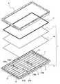
図1および図2に、本発明の第1実施形態に係るバックライト装置1を用いた液晶モジュールを示す。この液晶モジュールは、表示素子としての液晶パネル8と、液晶パネル8の裏側に配設されたバックライト装置1とを備えている。液晶パネル8の周縁部は、カバーフレーム9によってバックライト装置1に固定されている。なお、液晶モジュールは、液晶パネル8を制御する制御装置、およびバックライト装置1に電源を供給する、DC/DC電源等を備える駆動部などを有しているが、これらは公知のものが採用可能であり、それらの図示および説明は省略する。
(First embodiment)
1 and 2 show a liquid crystal module using the backlight device 1 according to the first embodiment of the present invention. The liquid crystal module includes a
バックライト装置1は、表示素子としての液晶パネル8を背面側から照明するものである。以下では、説明の便宜のために、バックライト装置1が光を放射する側(表面側:液晶パネル側、出射面側)を上方、その反対側(裏面側:光源側、入射面側)を下方と記載する場合がある。
The backlight device 1 illuminates a
具体的に、バックライト装置1は、所定方向(液晶パネル8と平行な方向)に配列された複数本の線状光源2と、線状光源2を液晶パネル8と反対側(線状光源2の配列面と直交する方向の一方)から収容するケース3と、ケース3に蓋をするように配置された拡散板6Aとを備えている。ケース3内には、該ケース3における線状光源2と対向する底面上に反射シート4が配設されているとともに、線状光源2の延在方向に離間して一対の支持部材5が配置されている。また、拡散板6A上には、拡散板6Aを透過した光を拡散または集光する、プリズムシートなどを含む光学シート7が積層されている。
Specifically, the backlight device 1 includes a plurality of
バックライト装置1は、一般に、平面視で線状光源2の延在方向に延びる長方形状をなしており、ケース3の底面および拡散板6Aも、線状光源2の延在方向が長手方向、線状光源2が配列された所定方向(以下「光源配列方向」という。)が短手方向の長方形状をなしている。
The backlight device 1 generally has a rectangular shape extending in the extending direction of the
本実施形態では、線状光源2として直管状の冷陰極蛍光ランプ(CCFL)が用いられており、これらが互いに平行に配列されている。そして、線状光源2の両端部が支持部材5で覆われている。ただし、ケース3内には、U字状の冷陰極蛍光ランプを配置することも可能である。この場合には、U字状のランプの直線部分が本発明の「線状光源」となる。
In the present embodiment, a straight-tube cold cathode fluorescent lamp (CCFL) is used as the
ケース3は、アルミニウム等の金属または樹脂で構成される。ケース3は、一方向に開口する箱状をなしており、線状光源2の配列面と平行な底面を構成する底壁と、この底壁の周縁部から立ち上がる周壁とを有している。また、本実施形態のケース3は、周壁の上端部に連設された鍔部も有している。
The
反射シート4は、ケース3の底面を略全面的に覆っている。反射シート4は、例えば金属箔で構成され、線状光源2から拡散板6Aと反対側に放射された光を拡散板6A側に反射する。
The
各支持部材5は、高反射性の材料で構成されている。このような高反射性の材料としては、例えば酸化チタンを混合したポリカーボネートを用いることができる。本実施形態では、各支持部材5は、一体成型されている。 Each support member 5 is made of a highly reflective material. As such a highly reflective material, for example, polycarbonate mixed with titanium oxide can be used. In this embodiment, each support member 5 is integrally molded.
各支持部材5は、図2に示すように、線状光源2の端部を保持するベース部51と、ベース部51の内側端部から外側に開くように斜め上向きに延びる反射部52とを有している。ベース部51の内側側面は、反射部52の内側側面と連続面を構成するように傾斜している。このため、線状光源2および反射シート4から支持部材5に向かって進む光は、ベース部51の内側側面および反射部52の内側側面によって拡散板6Aに向けて反射される。
As shown in FIG. 2, each support member 5 includes a
また、各支持部材5は、拡散板6Aを支持する第1支持部53と、液晶パネル8を支持する第2支持部55と、第1支持部53と第2支持部55とを一体的に連結する、拡散板6Aの端面と対向する縦壁部54とを有している。第1支持部53は、反射部52の上端部からケース3の底面と平行に外側に延びており、縦壁部54は、第1支持部53の外側端部から垂直に立ち上がっている。また、第2支持部55は、縦壁部54の上端部から第1支持部53と平行に張り出している。第1支持部53、第2支持部55および縦壁部54は、内側に開口する溝状の凹部5Aを形成しており、この凹部5Aに拡散板6Aの長手方向の端部が挿入されている。
Each support member 5 integrally includes a
さらに、各支持部材5は、第2支持部55の外側端部から上方に向かった後に外側に向かう断面略L字状の屈曲部57と、屈曲部57の外側端部からケース3の周壁に沿って垂れ下がる側壁部56と、カバーフレーム9を固定するための、屈曲部57の外側端部に連設された固定部58とを有している。
Furthermore, each support member 5 includes a
拡散板6Aは、線状光源2と液晶パネル8との間に配設され、線状光源2側の入射面から入射した光を拡散して液晶パネル8側の出射面から出射するもので、ポリスチレンやポリカーボネートなどの透明な樹脂の射出成形により形成されている。具体的には、図2のように、線状光源2を挟んで反射シート4と反対側に配設されており、線状光源2からの直射光および反射シート4からの反射光を内部に入射させる入射面と、内部で拡散した光を出射させる出射面とを有している。上述した光学シート7は出射面上に積層配置されている。
The
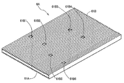
図3に拡散板6Aの上方の面(表面:液晶パネル側、出射面)の斜視図を、図4に拡散板6Aの下方の面(裏面:光源側、入射面)の斜視図を、それぞれ示す。これらの図に示すように、拡散板6Aの表面および裏面には、長手方向に光制御部61Aおよび光制御部61Bがそれぞれ形成されている。これらの光制御部61Aおよび光制御部61Bは、線状光源2に平行な縞模様を呈している。本実施形態では、光制御部61Aは、出射面を透過する光の屈折方向を規定する複数のプリズム構造体(断面三角形状の突条部)で構成されており、光制御部61Bは、入射面を透過する光の屈折方向を規定する複数のプリズム構造体(断面三角形状の突条部)で構成されている。
Upper surface of the diffusing
光制御部61Aおよび光制御部61Bは、線状光源2からの直射光および反射シート4からの反射光を光源配列方向に均一化するように構成されている。具体的には、各線状光源2の真上部分ではプリズム構造体のピッチが相対的に密に設定され、その間の部分では線状光源2から離れるにつれてプリズム構造体のピッチが徐々に粗くなるように設定されている。なお、光制御部の立体形状は、上述した形状に限定されるものではない。
The
従来のバックライト装置で用いられる拡散板は、通常は押し出し成形されるため、出射面に光制御部のみが形成されている。本実施形態にかかる拡散板6Aは、拡散板6Aの表裏両面に光制御部としての光学パターンを形成するように、金型に樹脂を流し込んで成形する。金型は、拡散板の表裏両面に形成される光学パターンであるプリズム構造体に対応した形状を備える。このような金型を用いて射出成形された拡散板6Aは、出射面に構成された光制御部61Aに加えて入射面に構成された光制御部61Bを備える。このため、1枚の拡散板6Aによりバックライト装置から照射された光を均一化させる効果を向上させることができるので、プリズムシート(光学シート)の枚数を減らすことができる。
The diffuser plate used in the conventional backlight device, usually because it is extruded, only the light control portion is formed on the exit surface. The
さらに、図4に示すように、この拡散板6Aの裏面の入射面において、拡散板支持部材31B1〜拡散板支持部材31B6に対応する位置には、その対応する部分を窪ませることにより形成した複数(ここでは6個)の当接部としての平滑部61B1〜平滑部61B6を備える。この平滑部61B1〜平滑部61B6には、図1の拡散板支持部材31B1〜拡散板支持部材31B6の先端がそれぞれ当接して、これらの拡散板支持部材31B1〜拡散板支持部材31B6により拡散板6Aが支持される。これにより、拡散板6Aが撓まないように支持することができる。なお、図1に示すように、拡散板支持部材31B1〜拡散板支持部材31B6は、線状光源2と他の線状光源2との間に設けられる。
Furthermore, as shown in FIG. 4, on the incident surface on the back surface of the
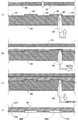
さらに、図4の平滑部61B1および平滑部61B2を含む断面図を図5に示す。この図5に示すように、拡散板支持部材31B1および拡散板支持部材31B2は、棒状の形状を備え、その先端部は、拡散板6Aを傷付けることのないように丸みを帯びている。平滑部61B1および平滑部61B2は、拡散板6Aの裏面側に設けられ、拡散板6Aを貫通しないように設けられた穴部で形成されている。拡散板支持部材31B1の先端は平滑部61B1に当接し、拡散板支持部材31B2の先端は、平滑部61B2に当接している。プリズム構造体ではなく、平滑な当接面を備えた平滑部61B1〜平滑部61B6に、拡散板支持部材31B1〜拡散板支持部材31B6が当接するので、拡散板6Aを安定して支持することができる。
Furthermore, FIG. 5 shows a cross-sectional view including the smoothing part 61B1 and the smoothing part 61B2 of FIG. As shown in FIG. 5, each of the diffusion plate support member 31B1 and the diffusion plate support member 31B2 has a rod shape, and its tip is rounded so as not to damage the
さらに詳しくは、図5に示すように、平滑部61B2は、射出成形時の樹脂注入口としてのゲート部分に残存する樹脂により形成される凸部としてのゲート凸部61B7を備える。なお、平滑部61B1にゲート凸部61B7を備えていても構わない。
拡散板6Aが射出成形される状態を、金型とともに図6に示す。この図6においては、金型100および金型200を拡散板の厚みまで接近させてから、樹脂を金型100と金型200との間に流し込む。なお、本発明は、このような樹脂成形の方法およびこれらの金型により製造される拡散板に限定されるものではない。
More specifically, as shown in FIG. 5, the smooth portion 61B2 includes a gate convex portion 61B7 as a convex portion formed by a resin remaining in a gate portion as a resin injection port at the time of injection molding. The smoothing portion 61B1 may include the gate convex portion 61B7.
A state in which the
図6(A)に示すように、金型100は、拡散板6Aの表面に形成される光制御部61A(プリズム構造体)対応した三角柱形状部102を備える。金型200は、拡散板6Aの裏面に形成される光制御部61B(プリズム構造体)に対応した三角柱形状部202を備えるとともに、平滑部に対応した円柱形状部204および円柱形状部206を備える。円柱形状部206は、金型に樹脂を流し込むためのゲート(樹脂通路)208を備える。
As shown in FIG. 6A, the
図6(B)に示すように、金型100と金型200を配置した状態で、金型200にホットランナ300を差し込んで、ゲート208より拡散板成形用の透明な液状の樹脂を注入し、その後図6(C)に示すように、樹脂が完全に硬化する前にホットランナ300からの樹脂注入を止めた後、ホットランナ300を金型200から抜くように動かすとともに、樹脂を完全に硬化させる。
As shown in FIG. 6B, with the
その後、図6(D)に示すように、金型100と金型200を取り外して樹脂成形品を取り出すことにより、拡散板6Aを製造することができる。
Thereafter, as shown in FIG. 6D, the
この図6(A)〜図6(D)に示すように、樹脂の射出成形により拡散板6Aを製造した場合に、ゲート208の位置に、ゲート208に残存した樹脂によりゲート凸部61B7が形成される。このゲート凸部61B7は、平滑部61B2における光源側に突出して構成される。ただし、このゲート凸部61B7は、平滑部61B2の内部に収まっているので、光学特性に影響を与えるものではない。また、図5に示すように、この拡散板支持部材31B2は、ゲート凸部61B7の位置以外で拡散板6Aに当接している。なお。平滑部61B2は、光制御部61Bを構成しないように拡散板6Aの裏面のプリズム構造体を窪ませた形状である。
As shown in FIGS. 6A to 6D, when the
本実施形態においては、ゲートが3ヶ所ある金型を用いているので、拡散板6Aには、3ヶ所のゲート凸部が形成される。平滑部61B2の他には、たとえば、平滑部61B4および平滑部61B6がゲート凸部を備える。一般的に、射出成形においては、その樹脂成形品の大きさにもよるが、少なくとも2〜3ヶ所のゲートが設けられて、樹脂が金型に均等に流し込まれるようになっている。本実施形態においては、このゲートの位置(ひいてはゲート凸部)が拡散板支持部材の位置に合致させてある。
In the present embodiment, since a mold having three gates is used, three gate convex portions are formed on the
このように、本実施形態においては、6ヶ所の拡散板支持部材が6ヶ所の平滑部に当接する。そのうちの3ヶ所の拡散支持部材の位置(当接部の位置)をゲート位置に合致させてあるので、3ヶ所の当接部にゲート凸部が形成されることになる。当接部の数は、ゲート数と同じであってもよく、全てのゲート位置に当接部が形成されることが好ましい。さらに、当接部の数をゲート数よりも多くすると、より多くの位置で拡散板6Aを支持できるので、より安定させることができる。なお、このような当接部の位置および個数(個数についてはゲート数以上)は、線状光源2が配置された間隙に当接部を設けること、当接部の個数が少なくても拡散板6Aの撓みを抑制できる位置に当接部を設けることが、好ましい。
Thus, in the present embodiment, the six diffusion plate support members abut on the six smooth portions. Of these, the positions of the three diffusion support members (the positions of the contact portions) are matched with the gate position, so that the gate protrusions are formed at the three contact portions. The number of contact portions may be the same as the number of gates, and the contact portions are preferably formed at all gate positions. Furthermore, if the number of contact portions is larger than the number of gates, the
なお、このようにするのではなく、すなわち、ゲートの位置が拡散板支持部材の位置以外であると、以下のような不具合が発生する。ゲートの位置が拡散板支持部材の位置ではないと、ゲート凸部がプリズム構造体の部分に形成される。このため、プリズム構造体による光学特性にゲート凸部が影響を与えてしまい、バックライト装置から照射された光を均一化させる効果を低下させてしまう可能性がある。これでは、拡散板の裏面にも光学パターンを設けた意味が薄れてしまい、光学シートの枚数を減らすこともできない。 It should be noted that the following problem occurs when the gate is not located at the position other than the position of the diffusion plate support member. If the position of the gate is not the position of the diffusion plate support member, the gate protrusion is formed in the prism structure portion. For this reason, a gate convex part affects the optical characteristic by a prism structure, and there exists a possibility of reducing the effect of equalizing the light irradiated from the backlight apparatus. In this case, the meaning of providing an optical pattern on the back surface of the diffusion plate is diminished, and the number of optical sheets cannot be reduced.
さらに、拡散板支持部材の先端は、当接部の平滑な部分に当接して、当接部のゲート凸部には当接しないため、拡散板支持部材が拡散板をさらに安定して支持することができる。 Furthermore, since the tip of the diffusion plate support member contacts the smooth portion of the contact portion and does not contact the gate convex portion of the contact portion, the diffusion plate support member supports the diffusion plate more stably. be able to.
以上のようにして、本実施形態に係るバックライト装置を用いた液晶モジュールによると、拡散板の表裏両面に光学パターンを設けて、拡散板の効果を向上させることができる。さらに、拡散板の裏面を窪ませた平滑部を構成したので、プリズム構造体の作用効果を維持しつつ、平滑部に拡散板支持部材を当接させることにより拡散板の安定性を高めることができる。さらに、この平滑部に射出成形時のゲート位置を合致させたので、ゲート凸部がプリズム構造体の位置ではなく平滑部に形成されるので、ゲート凸部が光学特性に悪い影響を与えることもない。 As described above, according to the liquid crystal module using the backlight device according to the present embodiment, the optical pattern can be provided on both the front and back surfaces of the diffusion plate to improve the effect of the diffusion plate. Furthermore, since the smooth part with the back surface of the diffuser plate recessed is formed, the stability of the diffuser plate can be improved by bringing the diffuser plate support member into contact with the smooth part while maintaining the effect of the prism structure. it can. Furthermore, since the gate position at the time of injection molding is matched with this smooth portion, the gate convex portion is formed not on the prism structure but on the smooth portion, so that the gate convex portion may adversely affect the optical characteristics. Absent.
(第2実施形態)
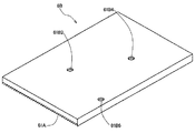
次に、本発明の第2実施形態に係るバックライト装置を説明する。なお、本実施形態のバックライト装置は、第1実施形態で説明したバックライト装置1の拡散板6Aを図7、図8に示す拡散板6Bに変更しただけのものであるので、以下においては、拡散板6Bについてのみ説明する。なお、図8は、図7に示す拡散板6Bの主要部の断面構造を示す断面図である。
(Second Embodiment)
Next, a backlight device according to a second embodiment of the present invention will be described. Note that the backlight device of this embodiment is obtained by changing the
拡散板6Bの上方の面(表面:液晶パネル側、出射面)は、拡散板6A(図3参照)と同じ構成を備える。拡散板6Bの下方の面(裏面:光源側、入射面)は、拡散板6A(図4参照)の光制御部61B(プリズム構造体)を備えない構成である。図7および図8に示すように、この拡散板6Bの裏面は、平面である。この拡散板6Bは、拡散板6Aと同じように射出成形して製造される。このような拡散板6Bであっても、拡散板6Aと同じように、平滑部61B2を備え、この平滑部61B2にゲート凸部61B7が形成されている。ゲート凸部61B7は、第1実施形態と同じく、金型に樹脂を流し込むためのゲート(樹脂通路)の位置に、樹脂通路に残存した樹脂により形成される。
The upper surface of the
この拡散板6Bによると、拡散板を射出成形して製造する場合に、この平滑部61B2に射出成形時のゲート位置を合致させたので、ゲート凸部61B7が拡散板裏面に突出して形成されることなく平滑部61B2に形成されるので、ゲート凸部61B7が光学特性に悪影響を与えることもない。
According to the
なお、この第2実施形態においては、拡散板支持部材に対応する位置に設ける当接部は、全ての当接部について、その対応する部分を窪ませた形状の平滑部を形成する必要はなく、少なくともゲート凸部61B7が形成される部分の当接部にのみ、図8に示すような平滑部を形成すればよい。 In the second embodiment, the abutting portion provided at the position corresponding to the diffusion plate support member does not need to form a smooth portion having a shape in which the corresponding portion is depressed for all the abutting portions. Further, it is only necessary to form a smooth portion as shown in FIG. 8 only at a contact portion where at least the gate convex portion 61B7 is formed.
(その他の実施形態)
上述した第1実施形態および第2実施形態では、各線状光源2が1本の冷陰極蛍光ランプで構成されていたが、各線状光源2は、複数のLEDで構成されていてもよい。このとき、複数のLEDは、直線上に並ぶように配列されるように構成されていてもよい。このようにLEDを用いて線状光源2を構成した場合でも、第1実施形態および第2実施形態と同様に、加工コストを上昇させることなく、光学特性に優れた拡散板を備えたバックライト装置を提供することができる。
(Other embodiments)
In the first embodiment and the second embodiment described above, each linear
また、上述した第1実施形態および第2実施形態では、光制御部が複数のプリズム構造体で構成されていたが、これに限定されない。光学特性を向上させる作用効果があり、かつ、光制御部を構成するために型(金型に限定されない)に樹脂を流し込んで成形する構造であれば、本発明の光制御部として採用できる。なお、立体形状の光制御部とは、上述のプリズム構造体を含み、他のいかなる形状の構造体であっても構わないことを示す。 Further, in the first embodiment and the second embodiment described above, the light control unit is configured by a plurality of prism structures, but is not limited thereto. Any structure that has the effect of improving the optical characteristics and is formed by pouring resin into a mold (not limited to a mold) to form the light control section can be adopted as the light control section of the present invention. Note that the three-dimensional light control unit includes the prism structure described above and may be any other shape structure.
本発明は、例えば、均一な輝度のバックライト装置を実現することができ、種々の用途のバックライト装置に適用可能である。 The present invention can realize, for example, a backlight device with uniform brightness, and can be applied to backlight devices for various purposes.
1 バックライト
2 線状光源
3 ケース
4 反射シート
5 支持部材
5A 凹部
52 反射部
53 第1支持部
54 縦壁部
55 第2支持部
6A,6B 拡散板
61 光制御部
8 液晶パネル(表示素子)
DESCRIPTION OF SYMBOLS 1
Claims (4)
光源を配置したケースと、
前記光源と前記表示素子との間に配設され、前記光源側の入射面から入射した光を拡散して前記表示素子側の出射面から出射する拡散板と、
前記ケースに設けられ、前記拡散板の光源側の入射面に当接して当該拡散板を支持する複数の支持部材とを備え、
前記拡散板は、前記入射面の前記支持部材に対応する位置に該支持部材の先端が当接する底面が形成された凹部を有し、該凹部の底面が前記光源側からの光を透過し、かつ前記凹部の底面のうち前記支持部材の先端が当接する位置以外の位置に凸部を有するものであることを特徴とするバックライト装置。 A backlight device disposed on the back side of the display element,
A case with a light source,
A diffusing plate disposed between the light source and the display element, diffusing light incident from the incident surface on the light source side and exiting from the output surface on the display element side;
A plurality of support members that are provided in the case and support the diffusion plate in contact with an incident surface on the light source side of the diffusion plate;
The diffusion plate has a recess formed with a bottom surface with which the tip of the support member abuts at a position corresponding to the support member of the incident surface, and the bottom surface of the recess transmits light from the light source side, The backlight device has a convex portion at a position other than the position where the tip of the support member abuts on the bottom surface of the concave portion.
前記バックライト装置によって背面側から照明される前記表示素子としての液晶パネルとを備えたことを特徴とする液晶モジュール。 The backlight device according to claim 1;
A liquid crystal module comprising: a liquid crystal panel as the display element illuminated from the back side by the backlight device.
Priority Applications (2)
| Application Number | Priority Date | Filing Date | Title |
|---|---|---|---|
| JP2010176550A JP5511072B2 (en) | 2010-08-05 | 2010-08-05 | Backlight device and liquid crystal module |
| US13/020,812 US8467015B2 (en) | 2010-08-05 | 2011-02-04 | Backlight unit and liquid crystal module |
Applications Claiming Priority (1)
| Application Number | Priority Date | Filing Date | Title |
|---|---|---|---|
| JP2010176550A JP5511072B2 (en) | 2010-08-05 | 2010-08-05 | Backlight device and liquid crystal module |
Publications (3)
| Publication Number | Publication Date |
|---|---|
| JP2012038519A JP2012038519A (en) | 2012-02-23 |
| JP2012038519A5 JP2012038519A5 (en) | 2013-04-11 |
| JP5511072B2 true JP5511072B2 (en) | 2014-06-04 |
Family
ID=45555912
Family Applications (1)
| Application Number | Title | Priority Date | Filing Date |
|---|---|---|---|
| JP2010176550A Expired - Fee Related JP5511072B2 (en) | 2010-08-05 | 2010-08-05 | Backlight device and liquid crystal module |
Country Status (2)
| Country | Link |
|---|---|
| US (1) | US8467015B2 (en) |
| JP (1) | JP5511072B2 (en) |
Families Citing this family (3)
| Publication number | Priority date | Publication date | Assignee | Title |
|---|---|---|---|---|
| CN102749732B (en) * | 2012-06-18 | 2015-07-15 | 歌尔声学股份有限公司 | LCD (Liquid Crystal Display) device and manufacturing method thereof |
| JP6964447B2 (en) * | 2017-06-29 | 2021-11-10 | パナソニック液晶ディスプレイ株式会社 | Display device |
| CN110824774B (en) * | 2019-11-26 | 2021-03-16 | 惠州市华星光电技术有限公司 | Backlight structure and display panel |
Family Cites Families (11)
| Publication number | Priority date | Publication date | Assignee | Title |
|---|---|---|---|---|
| US6858165B2 (en) * | 1998-08-06 | 2005-02-22 | Kyowa Electric And Chemical Co. Ltd. | Method of manufacturing plastic thin-plate article with protrusions on surface thereof |
| TW579438B (en) * | 1999-02-04 | 2004-03-11 | Keiwa Inc | Light diffusion plate and backlight device using the same |
| JP4166397B2 (en) * | 2000-01-13 | 2008-10-15 | アルプス電気株式会社 | Manufacturing method of optical member |
| US7213933B2 (en) * | 2004-01-02 | 2007-05-08 | Entire Technology Co., Ltd. | Direct type backlight module of diffuser plate and its manufacturing method thereof |
| US7380962B2 (en) * | 2004-04-23 | 2008-06-03 | Light Prescriptions Innovators, Llc | Optical manifold for light-emitting diodes |
| TWI406042B (en) | 2004-12-27 | 2013-08-21 | Samsung Display Co Ltd | Receiving container, backlight assembly having the receiving container, and display device having the backlight assembly |
| KR20060116549A (en) * | 2005-05-10 | 2006-11-15 | 삼성전자주식회사 | Back light unit and liquid crystal display apparatus employing the same |
| JP4933322B2 (en) | 2007-03-28 | 2012-05-16 | 住友化学株式会社 | Light diffusing plate, surface light source device, and liquid crystal display device |
| CN101784834B (en) * | 2007-08-08 | 2012-01-25 | 夏普株式会社 | Illuminating device for display device, display device, and television receiving apparatus |
| JP2010066664A (en) * | 2008-09-12 | 2010-03-25 | Nippon Zeon Co Ltd | Light diffusion plate, direct backlight device, and liquid crystal display device |
| US20100208161A1 (en) * | 2009-02-19 | 2010-08-19 | Victor Company Of Japan, Limited | Backlight device and liquid crystal display |
-
2010
- 2010-08-05 JP JP2010176550A patent/JP5511072B2/en not_active Expired - Fee Related
-
2011
- 2011-02-04 US US13/020,812 patent/US8467015B2/en active Active
Also Published As
| Publication number | Publication date |
|---|---|
| US20120033157A1 (en) | 2012-02-09 |
| JP2012038519A (en) | 2012-02-23 |
| US8467015B2 (en) | 2013-06-18 |
Similar Documents
| Publication | Publication Date | Title |
|---|---|---|
| US7894012B2 (en) | Backlight device and liquid crystal display device using the same | |
| JP4993096B2 (en) | Planar illumination device, transparent resin substrate thereof, and injection molding method of transparent resin substrate | |
| JP5211131B2 (en) | Backlight device and liquid crystal display device | |
| JP2012155236A (en) | Liquid crystal module | |
| KR100613839B1 (en) | Back light unit | |
| US20100165662A1 (en) | Backlight unit | |
| TWI240091B (en) | Light pipe having one or more integral diffusers | |
| JP2011040278A (en) | Planar illumination device | |
| JP2010020318A (en) | Liquid crystal display device | |
| US20180157117A1 (en) | Display device including backlight unit | |
| WO2020237934A1 (en) | Backlight module and liquid crystal module | |
| JP5511072B2 (en) | Backlight device and liquid crystal module | |
| JP2011090939A (en) | Planar light source device and liquid crystal display device using the same | |
| CN104633531A (en) | Lateral entrance type backlight module | |
| JP2008262766A (en) | Light guide plate, plane light source device, and liquid crystal display device | |
| KR101147095B1 (en) | Composite Light Guide Plate, and Backlight Unit Using the Same | |
| JP5638371B2 (en) | Planar light source device and display device | |
| TW201321861A (en) | Light guide plate structure and backlight module using the same | |
| WO2020237715A1 (en) | Backlight module and liquid crystal module | |
| JP5452356B2 (en) | Backlight device and liquid crystal module | |
| TWI413835B (en) | Backlight module and display apparatus | |
| US7954983B2 (en) | Optical component, manufacturing method of the same and backlight module | |
| US8628231B2 (en) | Diffusion plate and display apparatus having the same | |
| JP2008053213A (en) | Planar light emitting device, optical element and liquid crystal display device | |
| JP2012038519A5 (en) |
Legal Events
| Date | Code | Title | Description |
|---|---|---|---|
| A521 | Written amendment |
Free format text: JAPANESE INTERMEDIATE CODE: A523 Effective date: 20130227 |
|
| A621 | Written request for application examination |
Free format text: JAPANESE INTERMEDIATE CODE: A621 Effective date: 20130227 |
|
| A977 | Report on retrieval |
Free format text: JAPANESE INTERMEDIATE CODE: A971007 Effective date: 20131107 |
|
| A131 | Notification of reasons for refusal |
Free format text: JAPANESE INTERMEDIATE CODE: A131 Effective date: 20131113 |
|
| A521 | Written amendment |
Free format text: JAPANESE INTERMEDIATE CODE: A523 Effective date: 20131225 |
|
| TRDD | Decision of grant or rejection written | ||
| A01 | Written decision to grant a patent or to grant a registration (utility model) |
Free format text: JAPANESE INTERMEDIATE CODE: A01 Effective date: 20140319 |
|
| A61 | First payment of annual fees (during grant procedure) |
Free format text: JAPANESE INTERMEDIATE CODE: A61 Effective date: 20140324 |
|
| R151 | Written notification of patent or utility model registration |
Ref document number: 5511072 Country of ref document: JP Free format text: JAPANESE INTERMEDIATE CODE: R151 |
|
| LAPS | Cancellation because of no payment of annual fees |