JP5507338B2 - Steam turbine two-flow low-pressure configuration - Google Patents
Steam turbine two-flow low-pressure configuration Download PDFInfo
- Publication number
- JP5507338B2 JP5507338B2 JP2010115945A JP2010115945A JP5507338B2 JP 5507338 B2 JP5507338 B2 JP 5507338B2 JP 2010115945 A JP2010115945 A JP 2010115945A JP 2010115945 A JP2010115945 A JP 2010115945A JP 5507338 B2 JP5507338 B2 JP 5507338B2
- Authority
- JP
- Japan
- Prior art keywords
- turbine
- condenser
- exhaust path
- steam
- exhaust
- Prior art date
- Legal status (The legal status is an assumption and is not a legal conclusion. Google has not performed a legal analysis and makes no representation as to the accuracy of the status listed.)
- Expired - Fee Related
Links
- 238000004891 communication Methods 0.000 claims description 35
- 239000012530 fluid Substances 0.000 claims description 34
- 239000000498 cooling water Substances 0.000 claims description 7
- 238000009792 diffusion process Methods 0.000 description 6
- 238000000926 separation method Methods 0.000 description 3
- 238000004513 sizing Methods 0.000 description 2
- 230000007704 transition Effects 0.000 description 2
- UGFAIRIUMAVXCW-UHFFFAOYSA-N Carbon monoxide Chemical compound [O+]#[C-] UGFAIRIUMAVXCW-UHFFFAOYSA-N 0.000 description 1
- 241000270295 Serpentes Species 0.000 description 1
- 230000001133 acceleration Effects 0.000 description 1
- 238000009825 accumulation Methods 0.000 description 1
- 230000004323 axial length Effects 0.000 description 1
- 238000001816 cooling Methods 0.000 description 1
- 230000007423 decrease Effects 0.000 description 1
- 230000018109 developmental process Effects 0.000 description 1
- 238000010586 diagram Methods 0.000 description 1
- 230000009977 dual effect Effects 0.000 description 1
- 238000000034 method Methods 0.000 description 1
- 238000011064 split stream procedure Methods 0.000 description 1
- 230000003068 static effect Effects 0.000 description 1
Images


Classifications
-
- F—MECHANICAL ENGINEERING; LIGHTING; HEATING; WEAPONS; BLASTING
- F01—MACHINES OR ENGINES IN GENERAL; ENGINE PLANTS IN GENERAL; STEAM ENGINES
- F01D—NON-POSITIVE DISPLACEMENT MACHINES OR ENGINES, e.g. STEAM TURBINES
- F01D25/00—Component parts, details, or accessories, not provided for in, or of interest apart from, other groups
- F01D25/30—Exhaust heads, chambers, or the like
-
- F—MECHANICAL ENGINEERING; LIGHTING; HEATING; WEAPONS; BLASTING
- F01—MACHINES OR ENGINES IN GENERAL; ENGINE PLANTS IN GENERAL; STEAM ENGINES
- F01D—NON-POSITIVE DISPLACEMENT MACHINES OR ENGINES, e.g. STEAM TURBINES
- F01D1/00—Non-positive-displacement machines or engines, e.g. steam turbines
- F01D1/02—Non-positive-displacement machines or engines, e.g. steam turbines with stationary working-fluid guiding means and bladed or like rotor, e.g. multi-bladed impulse steam turbines
- F01D1/023—Non-positive-displacement machines or engines, e.g. steam turbines with stationary working-fluid guiding means and bladed or like rotor, e.g. multi-bladed impulse steam turbines the working-fluid being divided into several separate flows ; several separate fluid flows being united in a single flow; the machine or engine having provision for two or more different possible fluid flow paths
-
- F—MECHANICAL ENGINEERING; LIGHTING; HEATING; WEAPONS; BLASTING
- F01—MACHINES OR ENGINES IN GENERAL; ENGINE PLANTS IN GENERAL; STEAM ENGINES
- F01D—NON-POSITIVE DISPLACEMENT MACHINES OR ENGINES, e.g. STEAM TURBINES
- F01D3/00—Machines or engines with axial-thrust balancing effected by working-fluid
- F01D3/02—Machines or engines with axial-thrust balancing effected by working-fluid characterised by having one fluid flow in one axial direction and another fluid flow in the opposite direction
Description
本発明は、全体的に蒸気タービンに関し、より具体的には、蒸気タービン排気構成に関する。 The present invention relates generally to steam turbines, and more particularly to a steam turbine exhaust arrangement.
軸方向タービンからの排気蒸気の吐出、例えば、この排気蒸気の凝縮器への吐出では、蒸気の流れを可能な限り滑らかに提供し、渦流の集積によるエネルギー損失並びにこのような流れの乱流及び不均一性を最小限にすることが望ましい。通常、タービンからの排気は、排気フードに配向され、ここからタービンの軸線に本質的に垂直な方向でフードの吐出開口を通って凝縮器に入る。タービンの排気部における軸方向流から排気フードにおける半径方向流への円滑な移行、更に、これからこのフードの吐出開口での凝縮器への円滑な流れを達成することが望ましい。 Exhaust steam discharge from an axial turbine, for example discharge of this exhaust steam into a condenser, provides the steam flow as smoothly as possible, energy loss due to eddy current accumulation and turbulence of such flow and It is desirable to minimize non-uniformity. Typically, the exhaust from the turbine is directed to the exhaust hood from which it enters the condenser through the hood discharge opening in a direction essentially perpendicular to the turbine axis. It is desirable to achieve a smooth transition from an axial flow in the exhaust section of the turbine to a radial flow in the exhaust hood, and a smooth flow from here to the condenser at the discharge opening of the hood.
軸流タービンなどと共に使用するのに有効な排気フードの構成において、利用される何れかのガイド手段内での加速度損失を避けることが望ましく、更に、タービンにおいてエネルギーを最も効率的に変換するため及び接続される凝縮器に排気蒸気を効率的に供給するために排気フードの吐出開口で比較的均一な流れ分布を得ることが望ましい。 In exhaust hood configurations effective for use with axial flow turbines and the like, it is desirable to avoid acceleration losses in any of the guide means utilized, and to convert energy most efficiently in the turbine and In order to efficiently supply the exhaust vapor to the connected condenser, it is desirable to obtain a relatively uniform flow distribution at the discharge opening of the exhaust hood.
また、最終段バケットの出口平面において比較的均一な円周方向及び半径方向の圧力分布を達成することにより、タービンからの排気の前にタービンの最終段バケットにおいて最適な効率を達成するのが望ましい。通常は、可能な限り軸方向長さの短いフードを利用して、タービントレインの軸方向サイズを制限するようにしながらこれらの成果を得るようにする試みがなされてきた。 It is also desirable to achieve optimal efficiency in the final stage bucket of the turbine prior to exhaust from the turbine by achieving a relatively uniform circumferential and radial pressure distribution in the exit plane of the final stage bucket. . Attempts have been made to obtain these results, usually using a hood with the shortest axial length possible to limit the axial size of the turbine train.
従来技術では、タービンに接続された排気ダクトにおいて、蒸気の軸方向流れをほぼ半径方向流れに効果的に変えるために円滑に湾曲した表面を有するベーンを利用していた。タービンからの排気の軸方向流れを半径方向流れに変換するこのような構成の実施例は、Christ他による米国特許第3552877号で示されている。Herzogによる米国特許第4013378号などの軸流タービンの従来技術における排気フードの別の開発では、流れを更に円滑にするためにベーンの複数のセットを組み込んでいる。排気フードは、最終段バケットに隣接するタービンに接続された排気ダクトに配列されるガイドベーンの第1のセットを含む。これらのベーンは、蒸気流の軸方向からほぼ半径方向への比較的円滑な移行を可能にするよう湾曲している。ガイドリングは、ガイドベーンの第1のセットを円周方向に囲み、複数の2次ベーンは、このガイドベーンの周りに円周方向に間隔を置いて配置される。ベーンの第1のセットから2次ベーンに半径方向に吐出される蒸気は、2次ベーンによって排気フードの吐出開口に配向される。2次ベーンは、ガイドリングの周りに実質的に等間隔で配置され、これらのベーンから様々な角度の蒸気の吐出を生じるよう様々な角度で湾曲している。吐出角は、最終段バケットの出口平面にわたり、及び吐出開口の平面にわたり実質的に均一な流れ分布を得るように排気フードの吐出開口に向けて蒸気を配向するよう選択される。しかしながら、このようなベーンは、流れ条件の1つのセットについて最適化することができるが、他の流れでは著しく有効性が低い状態で作動している可能性がある。 The prior art has utilized vanes with smoothly curved surfaces in an exhaust duct connected to a turbine to effectively convert the axial flow of steam into a substantially radial flow. An example of such a configuration for converting axial flow of exhaust from a turbine to radial flow is shown in US Pat. No. 3,552,877 by Christ et al. Another development of exhaust hoods in prior art axial flow turbines, such as US Pat. No. 4,031,378 by Herzog, incorporates multiple sets of vanes to further smooth the flow. The exhaust hood includes a first set of guide vanes arranged in an exhaust duct connected to a turbine adjacent to the last stage bucket. These vanes are curved to allow a relatively smooth transition from the axial direction of the steam flow to a substantially radial direction. A guide ring circumferentially surrounds the first set of guide vanes, and a plurality of secondary vanes are circumferentially spaced around the guide vanes. Steam discharged radially from the first set of vanes to the secondary vanes is directed by the secondary vanes to the discharge opening of the exhaust hood. The secondary vanes are substantially equally spaced around the guide ring and are curved at various angles to produce various angles of vapor discharge from these vanes. The discharge angle is selected to direct the steam towards the exhaust hood discharge openings so as to obtain a substantially uniform flow distribution across the exit plane of the last stage bucket and over the plane of the discharge openings. However, such a vane can be optimized for one set of flow conditions, but may be operating with significantly less effectiveness in other flows.
例えば、ディフューザは蒸気タービンにおいて一般的に利用される。有効なディフューザは、タービン効率及び出力を改善することができる。残念ながら、このようなタービンに存在する複雑な流れパターン並びにスペース制限により生じる設計問題により、完全に効果的なディフューザの設計がほとんど不可能になる。多くの場合、その結果として、流れ面積の増大により蒸気速度が低下するので、静圧を上昇させるディフューザの能力を完全に又は部分的に無効にする流れ剥離が生じることになる。軸方向蒸気タービンと共に使用される下向きの排気フードでは、ディフューザ吐出から排気フード吐出への損失は、最上部から最下部まで変化する。最上部では、流れの大部分は180度転回して、ディフューザ及び内側ケーシングの上に置かれ、次いで下方に転回される。従って、最上部での圧力は、側部におけるよりも大きく、該側部の圧力は最下部におけるよりも大きい。 For example, diffusers are commonly used in steam turbines. An effective diffuser can improve turbine efficiency and power. Unfortunately, the complex flow patterns present in such turbines and the design issues arising from space limitations make it almost impossible to design a fully effective diffuser. In many cases, the result is a flow separation that completely or partially defeats the diffuser's ability to increase static pressure as the steam velocity decreases due to increased flow area. In a downward exhaust hood used with an axial steam turbine, the loss from diffuser discharge to exhaust hood discharge varies from top to bottom. At the top, most of the flow turns 180 degrees and is placed on the diffuser and inner casing and then turned downward. Thus, the pressure at the top is greater than at the side and the pressure at the side is greater than at the bottom.
排気フードの機能に更に付加される複雑な問題は、二重流低圧蒸気タービンなどの二重流蒸気タービンにおいて対向するタービンセクションから個別の凝縮器への排気処理の課題である。複数の圧力凝縮器が一般的に使用され、これらは2つの基本的な理由から熱消費率を改善する。これら凝縮器は低い平均背圧をもたらし、凝縮器から出る凝縮物は単一の圧力凝縮器よりも高い温度を有する。複数の圧力ユニットの背圧は、凝縮器の単位長さ当たりの排熱がより均一である理由からより低くなる。熱力学的には、これは、より低い平均温度差で、すなわちより効率的に伝達されることを意味する。凝縮器への複数の流路を備えた複流蒸気タービンは公知である(Nishioka、米国特許第4306418号)。 A further problem added to the function of the exhaust hood is the challenge of exhaust treatment from opposing turbine sections to individual condensers in a double flow steam turbine, such as a double flow low pressure steam turbine. Multiple pressure condensers are commonly used and these improve the heat consumption rate for two basic reasons. These condensers provide a low average back pressure and the condensate exiting the condenser has a higher temperature than a single pressure condenser. The back pressure of the plurality of pressure units is lower because the exhaust heat per unit length of the condenser is more uniform. Thermodynamically, this means that it is transmitted with a lower average temperature difference, ie more efficiently. Double flow steam turbines with multiple flow paths to the condenser are known (Nishioka, US Pat. No. 4,306,418).
従来、二重軸流蒸気タービンの対向するセクションは、該対向するセクションを囲む共通の排気フードに排気し、次いで共通の凝縮器に排気する。複数の凝縮器の個別のセクションの個々の凝縮器への排気のために、排気フードを第1のタービンセクション及び第2のタービンセクションの各々に分割するバッフルを利用することは公知である。このバッフル処理は更に、凝縮器を個別のセクションに分割し、凝縮器の各個別のセクションは、排気フードの分割セクションの1つと流体連通している。従って、対向するタービンセクションは、異なる作動圧力で個別の凝縮器セクションに排気することができる(Silverstri他、米国特許第4557113号を参照)。 Conventionally, opposing sections of a dual axial steam turbine exhaust to a common exhaust hood surrounding the opposing sections and then exhaust to a common condenser. It is known to utilize a baffle that divides an exhaust hood into each of a first turbine section and a second turbine section for exhausting the individual sections of the plurality of condensers into individual condensers. This baffle process further divides the condenser into individual sections, and each individual section of the condenser is in fluid communication with one of the divided sections of the exhaust hood. Thus, opposing turbine sections can be exhausted to separate condenser sections at different operating pressures (see Silverstr et al., US Pat. No. 4,557,113).
更に、複数蒸気タービンの対向するセクションの各々において出口からの排気流に垂直分割プレートを設けて、分割流を個別の凝縮器に配向することは公知である。より具体的には、垂直分割プレートは、内側流れガイドと外側流れガイドとの間に流れる流れを、タービン出口(タービンセクションのそれぞれの端部にある)のアニュラスから分離する。別の垂直分割プレートは、軸方向に沿って垂直に排気フードを分離する。次に、垂直に分割された排気フードは、個別の圧力の凝縮器と連通して配置され、タービンセクションからの排気の横方向の分離を可能にすることができる。横方向に分離された排気は、特定の凝縮器に配向することができる。 Furthermore, it is known to provide a vertical split plate in the exhaust stream from the outlet in each of the opposing sections of the multi-steam turbine to direct the split stream to individual condensers. More specifically, the vertical dividing plate separates the flow flowing between the inner and outer flow guides from the annulus of the turbine outlet (at each end of the turbine section). Another vertical dividing plate separates the exhaust hood vertically along the axial direction. The vertically divided exhaust hood can then be placed in communication with a separate pressure condenser to allow for lateral separation of the exhaust from the turbine section. The laterally separated exhaust can be directed to a specific condenser.
図1は、蒸気タービンの一部である、複流蒸気タービンの部分切り欠き斜視図を示す。図2は、排気流路を含む複流蒸気タービンの一部を示している。全体的に符号10で示される蒸気タービンは、複数のタービンバケット14を装着するロータ12を含む。内側ケーシング16はまた、複数のダイアフラム18を装着するよう示されている。中心に配置されたほぼ半径方向蒸気入口20は、タービンバケットとタービンの対向する軸方向側部上のステータブレードの各々に蒸気を加えてロータを駆動する。ダイアフラム18のステータベーン及び軸方向に隣接するバケット14は、タービンの種々の段を形成して1つの流路とし、更に、図示しない凝縮器に流すためにタービンの最終段から蒸気が排気されることは理解されるであろう。
FIG. 1 shows a partially cutaway perspective view of a double flow steam turbine, which is part of a steam turbine. FIG. 2 shows a portion of a double-flow steam turbine that includes an exhaust flow path. A steam turbine, generally designated 10, includes a
また、外側排気フード22が図示されており、該フードは、タービンの内側ケーシング並びに軸受のような他の部品を囲み且つ支持する。タービンは、1つ又はそれ以上の凝縮器に流すために、タービンから出口26に排気する蒸気を案内する蒸気ガイド24を含む。タービン、軸受、及び補助部品を支持する排気フードを使用すると、排気蒸気経路が蛇行して圧力損失を生じ易くなり、結果として性能及び効率の低下が生じる。複数の支持構造を排気フード22内に設け、排気フードを固定して、蒸気排気流を誘導するのを助ける。例示的な支持構造30は、蒸気タービン10からの蒸気排気流35を受け取り且つ配向するよう位置付けられる。蒸気の拡散は、排気フード22内の容積に制限される。
Also shown is an
垂直分割器を備えた上述の従来の排気フード構成は、タービン出口からの排気の横方向分離に対処する。しかしながら、従来の排気フード構成は、タービン出口からの排気流の垂直分割をもたらすことにはならない。従って、タービン出口排気アニュラスの上側及び下側半分からの流れを垂直方向に分離する排気構成を提供することが有利とすることができる。 The conventional exhaust hood configuration described above with a vertical divider addresses the lateral separation of the exhaust from the turbine outlet. However, conventional exhaust hood configurations do not provide a vertical split of the exhaust flow from the turbine outlet. It can therefore be advantageous to provide an exhaust arrangement that vertically separates the flow from the upper and lower halves of the turbine outlet exhaust annulus.
本発明は、タービンセクションの出口と凝縮器との間の蒸気タービンの排気構成に関する。 The present invention relates to an exhaust arrangement for a steam turbine between a turbine section outlet and a condenser.
本発明の第1の態様によれば、蒸気タービン用の排気構成が提供される。排気構成は、第1の凝縮器と、該第1の凝縮器と流体連通した第1のタービン出口を有する第1のタービンセクションとを含む。少なくとも1つの外部排気経路が第1のタービン出口の上側部分に接続され、少なくとも1つの外部排気経路が第1のタービン出口の下側部分に接続される。第1のタービン出口の上側部分に接続された少なくとも1つの外部排気経路は、第1の凝縮器に流体連通して接続され、第1のタービン出口の下側部分に接続された少なくとも1つの外部排気経路は、第1の凝縮器に流体連通して接続される。 According to a first aspect of the present invention, an exhaust arrangement for a steam turbine is provided. The exhaust arrangement includes a first condenser and a first turbine section having a first turbine outlet in fluid communication with the first condenser. At least one external exhaust path is connected to the upper portion of the first turbine outlet, and at least one external exhaust path is connected to the lower portion of the first turbine outlet. At least one external exhaust path connected to the upper portion of the first turbine outlet is in fluid communication with the first condenser and is connected to the lower portion of the first turbine outlet. The exhaust path is connected in fluid communication with the first condenser.
本発明の第2の態様によれば、蒸気タービンシステムが提供される。蒸気タービンは、第1のタービン出口を有する第1のタービンセクションと、該第1のタービンセクションの第1のタービン出口と流体連通した第1の凝縮器とを含む。少なくとも1つの外部排気経路が第1のタービン出口の上側部分に接続され、少なくとも1つの外部排気経路が第1のタービン出口の下側部分に接続される。第1のタービン出口の上側部分に接続された少なくとも1つの外部排気経路は、第1の凝縮器に流体連通して接続される。第1のタービン出口の下側部分に接続された少なくとも1つの外部排気経路は、第1の凝縮器に流体連通して接続される。 According to a second aspect of the present invention, a steam turbine system is provided. The steam turbine includes a first turbine section having a first turbine outlet and a first condenser in fluid communication with the first turbine outlet of the first turbine section. At least one external exhaust path is connected to the upper portion of the first turbine outlet, and at least one external exhaust path is connected to the lower portion of the first turbine outlet. At least one external exhaust path connected to the upper portion of the first turbine outlet is connected in fluid communication with the first condenser. At least one external exhaust path connected to the lower portion of the first turbine outlet is connected in fluid communication with the first condenser.
本発明の別の態様によれば、蒸気タービンシステムが提供される。蒸気タービンシステムは、第1のタービン出口を有する第1のタービンセクションと、第2のタービン出口を有する第2のタービンセクションとを備えた複流蒸気タービンを含む。高圧タービン、中圧タービン、又はその両方のタービンは、複流蒸気タービンのロータシャフトと回転加納に接続された共通のロータシャフトを含む。第1の凝縮器は、第1のタービンセクションの第1のタービン出口と流体連通して設けられ、第2の凝縮器は、第2のタービンセクションの第2のタービン出口と流体連通して設けられる。 According to another aspect of the invention, a steam turbine system is provided. The steam turbine system includes a double-flow steam turbine having a first turbine section having a first turbine outlet and a second turbine section having a second turbine outlet. The high pressure turbine, the intermediate pressure turbine, or both turbines include a common rotor shaft connected in rotation with the rotor shaft of the double flow steam turbine. The first condenser is provided in fluid communication with the first turbine outlet of the first turbine section, and the second condenser is provided in fluid communication with the second turbine outlet of the second turbine section. It is done.
少なくとも1つの外部排気経路は、第1のタービン出口の上側部分に接続され、更に、第1の凝縮器と流体連通して接続される。少なくとも1つの外部排気経路は、第1のタービン出口の下側部分に接続され、更に、第1の凝縮器と流体連通して接続される。少なくとも1つの外部排気経路は、第2のタービン出口の上側部分に接続され、更に、第2の凝縮器と流体連通して接続される。少なくとも1つの外部排気経路は、第2のタービン出口の下側部分に接続され、更に、第2の凝縮器と流体連通して接続される。 At least one external exhaust path is connected to the upper portion of the first turbine outlet and is further connected in fluid communication with the first condenser. At least one external exhaust path is connected to the lower portion of the first turbine outlet and is further connected in fluid communication with the first condenser. At least one external exhaust path is connected to the upper portion of the second turbine outlet and is further connected in fluid communication with the second condenser. At least one external exhaust path is connected to the lower portion of the second turbine outlet and is further connected in fluid communication with the second condenser.
本発明のこれら及び他の目的並びに利点は、図面及び添付の請求項を併用しながら本発明の例示的な実施形態の以下の詳細な説明を詳細に検討することによって完全に理解され認識されるであろう。 These and other objects and advantages of the present invention will be fully understood and appreciated by studying the following detailed description of exemplary embodiments of the invention in conjunction with the drawings and the appended claims. Will.
本発明の以下の実施形態は、タービン排気出口アニュラスの上側半分及び下側半分に対する個別の外部排気ディフューザ経路を提供し、これにより従来の排気フードにより制限されない外部排気経路を通るタービン排気の個別の上側及び下側半分の有利な拡散を可能にし、更に、外部排気経路を複数の凝縮器に排気できるようにすることを含む、多くの利点を有する。 The following embodiments of the present invention provide separate external exhaust diffuser paths for the upper and lower halves of the turbine exhaust outlet annulus, whereby individual turbine exhaust through an external exhaust path that is not limited by a conventional exhaust hood. It has a number of advantages, including allowing advantageous diffusion of the upper and lower halves, and also allowing the external exhaust path to be exhausted to multiple condensers.
図3Aは、蒸気タービンの第1のセクションからの排気構成についての第1の実施形態の側面図を示している。タービン排気構成300は、蒸気タービン301の第1のタービンセクション305を含み、該蒸気タービンは、図1及び図2で説明されるような、ロータ、ブレード、ダイアフラムケーシング、及び内部蒸気流路を含む。第1のタービンセクション305は、ロータにエネルギーを送給する蒸気入口流れ310を通し、第1のタービン出口315内に排気する。第1のタービン出口315は、上側部分316及び下側部分317を含むことができる。第1のタービン出口315の上側部分316は、排気蒸気の拡散のために1つ又はそれ以上の外部排気経路に排気することができる。第1のタービン出口315の下側部分317は、排気蒸気の拡散のために1つ又はそれ以上の外部排気経路に排気することができる。図3Aは、第1のタービン出口315の上側部分316から第1の凝縮器330への単一の外部排気経路320と、第1のタービン出口315の下側部分317から第1の凝縮器330への単一の外部排気経路325とを示している。図3Bは、蒸気タービンの第1のセクションからの排気構成に対する第1の実施形態の端面図を示す。排気経路320及び325は、外部のタービンセクション305と流体連通することができる。
FIG. 3A shows a side view of the first embodiment for the exhaust configuration from the first section of the steam turbine. The
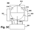
図3Cは、蒸気タービンの第1のセクションから排気構成345に対する第2の実施形態の端面図を示す。本明細書では第1のタービン出口315の上側部分は、第1の上側部分318及び第2の上側部分319を含む。第1の上側外部排気経路321は、第1の上側部分318から排気を引き込み、該排気を第1の凝縮器330に送給することができる。第2の上側外部排気経路322は、第2の上側部分319から排気を引き込み、該排気を第1の凝縮器330に送給することができる。単一の外部排気経路320を含むこの実施形態では、第1の凝縮器330と流体連通した第1のタービン出口315の下側部分からの排気を引き込むことができる。図示していないが、別の実施形態は、第1のタービン出口の複数の下側半分と第1の凝縮器との間に複数の外部排気経路を含むことができる。
FIG. 3C shows an end view of the second embodiment for the exhaust arrangement 345 from the first section of the steam turbine. As used herein, the upper portion of the
外部排気経路320、321、322、325は、導管の種々の形状及びサイズを含む、蒸気タービンの外部にある排気導管を含むことができる。外部排気経路は、上述のようなタービン出口セクションと第1の凝縮器330との間で流体連通して設けられる。外部排気経路は更に、タイ335と蒸気タービンから下流側で流体連通して共につなぐことができる。外部排気構成の別の変形形態では、外部排気経路は、第1の凝縮器と流体連通している共通導管に蒸気タービンの外部で併合することができる。
図4Aは、複流蒸気タービンの対向する端部からの排気構成に対する第3の実施形態の側面図を示す。複流蒸気タービン401の排気構成400は、上述のように、第1のタービンセクション305及び関連する排気経路と、第2のタービンセクション405及び関連する排気経路を含む。第2のタービンセクション405は、図1及び図2に示すように、ロータ、ブレード、ダイアフラム、ケーシング、及び蒸気流路を含むことができる。第2のタービンセクション405は、エネルギーをロータ(ロータ)に送給する蒸気入口流れ410を通し、第2のタービン出口415内に排気する。第2のタービン出口415は、上側部分416及び下側半分417を含むことができる。第2のタービン出口415の上側部分416は、排気蒸気の拡散のために1つ又はそれ以上の外部排気経路に排気することができる。第2のタービン出口415の下側部分417は、排気蒸気の拡散のために1つ又はそれ以上の外部排気経路に排気することができる。図4Aは、第2のタービン出口415の上側部分416から第2の凝縮器430への単一の外部排気経路420と、第2のタービン出口415の下側部分417から第2の凝縮器430への単一の外部排気経路425とを示している。図4Bは、蒸気タービンの第2のセクションからの排気構成に対する第3の実施形態の端面図を示す。図4Bは、第1のタービンセクション及び第2のタービンセクションの端面図を表しており、ここで第2のタービンセクションの参照符号は括弧内に提示される。タイ接続435は更に、第2のタービン出口415から下流側の外部排気経路420、425を流体連通して接続することができる。更に、タイ接続435から下流側では、外部排気経路420、425が第2の凝縮器430への共通の外部排気経路に併合することができる。
FIG. 4A shows a side view of a third embodiment for an exhaust configuration from opposite ends of a double flow steam turbine. The
図4Cは、複流蒸気タービンの排気構成にタイする第3の実施形態の端面図を示している。図4Cは、第1のタービンセクション及び第2のタービンセクションの端面図を表し、ここで第2のタービンセクションの参照符号は括弧内に提示される。本明細書では、第2のタービン出口415の上側部分は、第1の上側部分418及び第2の上側部分419を含む。第1の外部排気経路421は、第1の上側部分418から排気を引き込み、第2の凝縮器430に排気を送給することができる。第2の外部排気経路422は、第2の上側部分419から排気を引き込み、第2の凝縮器430に排気を送給することができる。この実施形態において、単一の外部排気経路425を含むこの実施形態では、第1の凝縮器430と流体連通した第2のタービン出口415の下側部分から排気を引き込むことができる。図示していないが、別の実施形態は、第2のタービン出口の複数の下側半分と第2の凝縮器との間に複数の外部排気経路を含むことができる。図4Cの端面図はまた、第1のタービンセクションに対する排気構成を表すことができる。
FIG. 4C shows an end view of a third embodiment tied to the exhaust configuration of a double flow steam turbine. FIG. 4C depicts an end view of the first turbine section and the second turbine section, where the reference numbers for the second turbine section are presented in parentheses. As used herein, the upper portion of the
本発明の別の態様において、図4Cで表される複流低圧タービンの各端部上の最終段バケットにおいて、異なるアニュラス区域を設けることができる。例えば、図4Cにおいて、第1のタービンセクション305は、第2のタービンセクション405における出口アニュラス区域480よりも大きな出口アニュラス区域380を含むことができる。大きなアニュラス区域では、第1のタービンセクション305は、より小さな出口アニュラス区域を有する第2のタービンセクション405よりも大きな出力及び推進力を生成することができる。第1のタービンセクションからの外部排気経路を第1の凝縮器に備えることができ、第2のタービンセクションからの外部排気経路を第2の凝縮器に備えることができ、ここで、それぞれの凝縮器の冷却表面のサイズ決定が既知であり、且つ冷却水の流量及び温度が選択可能であることにより、第1の凝縮器の真空は、第2の凝縮器の真空に比べてより高真空に維持することができる。更に、第1の凝縮器330及び第2の凝縮器430は、単一の統合凝縮器490の一部とすることができる。更にまた、第1の凝縮器330を通る冷却水流370及びび第2の凝縮器430を通る冷却水流470は、第1の凝縮器から第2の凝縮器を通って直列に流れることができる。
In another aspect of the invention, different annulus zones may be provided in the final stage bucket on each end of the double flow low pressure turbine represented in FIG. 4C. For example, in FIG. 4C, the
更にまた、前述の図がタービンの真下に位置付けられる凝縮器への排気を関連付けたのに対し、本発明は、側方排気の吐出を企図することができる点は理解できる。タービンから該タービンに隣接して装着される凝縮器への側方排気吐出は、これらの大型の構成要素の垂直方向の相当な積み重ねを避けるためであることが知られている。図5Aは、複流低圧蒸気タービン520から、発電機545と共通の支持構造540上に装着された凝縮器530への従来の側方排気を示している。従来の側方排気フード510は、蒸気タービン520からの蒸気排気を凝縮器530に配向する。図5Bは、複流蒸気タービンから側方凝縮器への排気流の第5の実施形態の端面図を示している。排気フード550は、タービン出口555を密閉する。タービン出口555は、隣接部分560と、側方凝縮器(図5A、530)との物理的関連で対向部分565とを含むことができる。対向部分565は更に、第1の対向部分566及び第2の対向部分567に分割することができる。排気流路565は、タービン出口555の隣接部分560から側方凝縮器590まで設けることができる。排気流路575は、タービン出口555の第1の対向部分566から側方凝縮器590まで設けることができ、排気経路580は、第2の対向部分567から側方凝縮器590まで設けることができる。
Still further, it can be appreciated that, while the preceding figures relate to exhaust to a condenser located directly below the turbine, the present invention can contemplate discharge of side exhaust. It is known that the side exhaust discharge from a turbine to a condenser mounted adjacent to the turbine is to avoid significant vertical stacking of these large components. FIG. 5A shows a conventional side exhaust from a double flow low
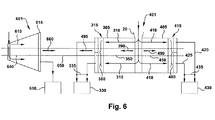
図6は、排気制御により可能にされた複流蒸気タービンの正味推力による単流タービンの推力平衡の側面図を示している。単流タービン600のロータ640は、共通シャフト650により複流蒸気タービン401のロータ350、450と機械的に接続される。単流蒸気タービン601は、高圧蒸気タービン及び/又は中圧蒸気タービンを含むことができる。単流蒸気タービン601は、タービンセクション605を備え、該タービンセクションは、図1及び図2で説明するように、ロータ、ブレード、ダイアフラム、ケーシング、及び蒸気流路を含むことができる。タービンセクション605は、ロータにエネルギーを送給する蒸気入口流れ610を通し、タービン出口615内に排気する。ロータ640上の単流蒸気タービン600の蒸気作用によって、共通シャフト650上に正味推力をもたらす。複流蒸気タービン401内では、蒸気流れ310が推力390をもたらし、蒸気流れ410が推力490をもたらす。推力3990、490は対向する方向にあるので、結果として正味推力495が得られ、共通シャフト650上のそれぞれのロータを通じて作用される。第1のタービンセクション305からの出口アニュラス区域380及び第2のタービンセクション405からの出口アニュラス区域480の選択的サイズ決定により、単流蒸気タービン600に対する正味推力600に対して大きさが等しく方向が反対であるように、正味推力495を設定可能にすることができる。組み合わされた蒸気単流タービン/蒸気複流タービンに対する平衡推力により、共通シャフト650用の大型で高価な推力軸受の必要性が排除される。
FIG. 6 shows a side view of the thrust balance of a single flow turbine with the net thrust of a double flow steam turbine enabled by exhaust control. The
本発明の種々の実施形態について説明してきたが、本発明の態様は記載された実施形態の一部のみを含むことができる点を理解されたい。 Although various embodiments of the present invention have been described, it should be understood that aspects of the present invention may include only some of the described embodiments.
10 蒸気ター
ビン
12 ロータ
14 バケット
16 ケーシング
18 ダイアフラム
20 蒸気入口
22 排気フード
24 蒸気ガイド
26 出口
30 支持構造
35 蒸気排気流
300 タービン排気構成
301 蒸気タービン
305 第1のタービンセクション
310 入口蒸気流れ
315 第1のタービン出口
316 上側部分
317 下側部分
318 第1の上側部分
319 第2の上側部分
320 上側部分からの外部排気経路
321 第1の上側外部排気経路
322 第2の上側外部排気経路
325 下側部分からの外部排気経路
330 第1の凝縮器
331 第1の凝縮器の真空
335 タイ接続
380 最終段蒸気経路区域
390 第1のタービンセクションからの推力
400 タービン排気構成
401 蒸気タービン
405 第2のタービンセクション
410 入口蒸気流れ
415 第2のタービン出口
416 上側部分
417 下側部分
418 第1の上側部分
419 第2の上側部分
420 上側部分からの外部排気経路
421 第1の上側外部排気経路
422 第2の上側外部排気経路
425 下側部分からの外部排気経路
430 第2の凝縮器
431 第2の凝縮器の真空
435 タイ接続
480 第2のタービンセクションの最終蒸気経路区域
490 第2のタービンセクションの推力
601 HP/IPタービン
605 タービンセクション
610 HP/IP蒸気流れ
615 HP/IP出口
640 HP/IPロータシャフト
660 HP/IP推力
10
Claims (9)
第1の凝縮器(330)と、
前記第1の凝縮器(330)と流体連通した第1のタービン出口(315)を含む第1のタービンセクション(305)と、
前記第1のタービン出口(315)の上側部分(316)に接続された少なくとも1つの外部排気経路(320)と、
前記第1のタービン出口(315)の下側部分(317)に接続された少なくとも1つの外部排気経路(325)と
を備えており、前記第1のタービン出口(315)の上側部分(316)に接続された少なくとも1つの外部排気経路(320)が、前記第1の凝縮器(330)に流体連通して接続され、前記第1のタービン出口(315)の下側部分(317)に接続された少なくとも1つの外部排気経路(325)が、前記第1の凝縮器(330)に流体連通して接続され、前記蒸気タービン(401)が、第2の凝縮器(430)と流体連通した第2のタービン出口(415)を有する複流蒸気タービンを備えており、前記第2のタービン出口(415)の上側部分(416)に接続された少なくとも1つの外部排気経路(420)が、前記第2の凝縮器(430)と流体連通しており、前記第2のタービン出口(415)の下側部分(417)に接続された少なくとも1つの外部排気経路(425)が、前記第2の凝縮器(430)と流体連通している、蒸気タービン(401)用の排気構成(400)。 An exhaust configuration (300) for a steam turbine ( 401 ), wherein the exhaust configuration is
A first condenser (330);
A first turbine section (305) including a first turbine outlet (315) in fluid communication with the first condenser (330);
At least one external exhaust path (320) connected to the upper portion (316) of the first turbine outlet (315);
At least one external exhaust path (325) connected to the lower part (317) of the first turbine outlet (315), the upper part (316) of the first turbine outlet (315) At least one external exhaust path (320) connected to the first condenser (330) in fluid communication and connected to a lower portion (317) of the first turbine outlet (315) And at least one external exhaust path (325) connected in fluid communication with the first condenser (330) and the steam turbine (401) in fluid communication with the second condenser (430) A double flow steam turbine having a second turbine outlet (415) is provided, wherein at least one external exhaust path (420) connected to the upper portion (416) of the second turbine outlet (415). At least one external exhaust path (425) in fluid communication with the second condenser (430) and connected to a lower portion (417) of the second turbine outlet (415) includes the second condenser (430). An exhaust arrangement (400) for the steam turbine (401) in fluid communication with the condenser (430) of the engine.
前記第1のタービン出口(315)の下側部分(317)に接続された少なくとも1つの外部排気経路(325)が単一の外部排気経路を含む、請求項1記載の蒸気タービン(401)用の排気構成(300)。 A first upper external exhaust path, wherein at least one external exhaust path (320) connected to the upper portion (316) of the first turbine outlet (315) is in fluid communication with the first condenser (330). (321) and a second upper external exhaust path (322) in fluid communication with the first condenser (330),
Comprising at least one external exhaust path (325) is a single external exhaust path connected to the lower portion (317) of said first turbine outlet (315), a steam turbine according to claim 1, wherein (401) exhaust configuration of (300).
前記第2のタービン出口(415)の下側部分(417)に接続された少なくとも1つの外部排気経路(425)が単一の外部排気経路を含む、請求項1又は請求項2記載の蒸気タービン(401)用排気構成(400)。 A first upper external exhaust path in fluid communication with the second condenser (430), wherein at least one external exhaust path (420) connected to the upper portion (416) of the second turbine outlet (415). and (421), said second condenser (430) and has Nde including a second upper external exhaust path in fluid communication (422),
At least one external exhaust path (425) comprises a single external exhaust path, a steam turbine according to claim 1 or claim 2, wherein connected to the lower portion (417) of said second turbine outlet (415) (401) Exhaust configuration (400).
前記第2のタービン出口(415)の上側部分(416)に接続された少なくとも1つの外部排気経路(420)が、前記第2のタービン出口(415)の下側部分(417)に接続された少なくとも1つの外部排気経路(425)と流体連通して接続し、前記第2の凝縮器(430)への組み合わされた排気経路を形成する、請求項1記載の蒸気タービン(401)用排気構成(400)。 At least one external exhaust path (320) connected to the upper portion (316) of the first turbine outlet (315) was connected to the lower portion (317) of the first turbine outlet (315). Connecting in fluid communication with at least one external exhaust path (325) to form a combined exhaust path to the first condenser (330);
At least one external exhaust path (420) connected to the upper portion (416) of the second turbine outlet (415) was connected to the lower portion (417) of the second turbine outlet (415). The exhaust arrangement for a steam turbine (401) of claim 1 , wherein the exhaust arrangement is in fluid communication with at least one external exhaust path (425) to form a combined exhaust path to the second condenser (430). (400).
前記第2のタービン出口(415)に接続された前記第1の上側外部排気経路(421)及び第2の上側外部排気経路(422)が、前記第2のタービン出口(415)の下側部分(417)に接続された少なくとも1つの外部排気経路(425)と流体連通して接続し、前記第2の凝縮器(430)への組み合わされた排気経路を形成する、請求項3記載の蒸気タービン(401)用排気構成(400)。 The first upper external exhaust path (321) and the second upper external exhaust path (322) connected to the first turbine outlet (315) are located below the first turbine outlet (315). Connecting in fluid communication with at least one external exhaust path (325) connected to portion (317) to form a combined exhaust path to the first condenser (330);
The first upper external exhaust path (421) and the second upper external exhaust path (422) connected to the second turbine outlet (415) are a lower portion of the second turbine outlet (415). The steam of claim 3 , wherein the steam is connected in fluid communication with at least one external exhaust path (425) connected to (417) to form a combined exhaust path to the second condenser (430). Exhaust configuration (400) for turbine (401).
前記高圧タービン及び中圧タービン(601)のうちの少なくとも1つが、前記共通ロータシャフト(650)に提示される推力(660)を生成し、
前記複流蒸気タービン(401)の第1のタービンセクション(305)が、前記複流蒸気タービン(401)の第2のタービンセクション(405)の最終段蒸気経路区域(480)よりも大きな最終段蒸気経路区域(380)を含み、これにより、組み合わされて、前記共通シャフト(650)に対し定格動作条件で正味推力を実質的に平衡化する推力(495)を生成する、請求項8記載の蒸気タービン(401)用排気構成(400)。
Further comprising at least one of a high pressure turbine and a medium pressure turbine (601) including a common rotor shaft (650) rotatably connected to the rotor shaft (350) / (450) of the double flow steam turbine (401). ,
At least one of the high and medium pressure turbines (601) generates a thrust (660) that is presented to the common rotor shaft (650);
A final stage steam path in which the first turbine section (305) of the double flow steam turbine (401) is larger than the final stage steam path area (480) of the second turbine section (405) of the double flow steam turbine (401). The steam turbine of claim 8 , comprising a section (380), which is combined to produce a thrust (495) that substantially balances the net thrust at rated operating conditions for the common shaft (650). (401) Exhaust configuration (400).
Applications Claiming Priority (2)
| Application Number | Priority Date | Filing Date | Title |
|---|---|---|---|
| US12/473,740 US8286430B2 (en) | 2009-05-28 | 2009-05-28 | Steam turbine two flow low pressure configuration |
| US12/473,740 | 2009-05-28 |
Publications (3)
| Publication Number | Publication Date |
|---|---|
| JP2010276020A JP2010276020A (en) | 2010-12-09 |
| JP2010276020A5 JP2010276020A5 (en) | 2013-07-04 |
| JP5507338B2 true JP5507338B2 (en) | 2014-05-28 |
Family
ID=42335053
Family Applications (1)
| Application Number | Title | Priority Date | Filing Date |
|---|---|---|---|
| JP2010115945A Expired - Fee Related JP5507338B2 (en) | 2009-05-28 | 2010-05-20 | Steam turbine two-flow low-pressure configuration |
Country Status (4)
| Country | Link |
|---|---|
| US (1) | US8286430B2 (en) |
| EP (1) | EP2264286A3 (en) |
| JP (1) | JP5507338B2 (en) |
| RU (1) | RU2538215C2 (en) |
Families Citing this family (6)
| Publication number | Priority date | Publication date | Assignee | Title |
|---|---|---|---|---|
| US9051843B2 (en) | 2011-10-28 | 2015-06-09 | General Electric Company | Turbomachine blade including a squeeler pocket |
| US9255480B2 (en) * | 2011-10-28 | 2016-02-09 | General Electric Company | Turbine of a turbomachine |
| US8992179B2 (en) | 2011-10-28 | 2015-03-31 | General Electric Company | Turbine of a turbomachine |
| DE102015213257A1 (en) * | 2015-07-15 | 2017-01-19 | Siemens Aktiengesellschaft | Abdampfgehäuse for a turbine, turbine frame, turbine housing and mounting system |
| WO2017145404A1 (en) * | 2016-02-25 | 2017-08-31 | 三菱日立パワーシステムズ株式会社 | Condenser and steam turbine plant provided with same |
| US10570781B2 (en) | 2018-03-15 | 2020-02-25 | General Electric Technology Gmbh | Connection system for condenser and steam turbine and methods of assembling the same |
Family Cites Families (18)
| Publication number | Priority date | Publication date | Assignee | Title |
|---|---|---|---|---|
| GB105933A (en) * | 1916-02-04 | 1917-05-04 | Karl Baumann | Improvements in or relating to Steam Turbines. |
| US1375076A (en) * | 1917-09-29 | 1921-04-19 | Westinghouse Electric & Mfg Co | Radial-flow steam-turbine |
| CH484358A (en) * | 1968-02-15 | 1970-01-15 | Escher Wyss Ag | Exhaust housing of an axial turbo machine |
| US4013378A (en) * | 1976-03-26 | 1977-03-22 | General Electric Company | Axial flow turbine exhaust hood |
| US4306418A (en) * | 1978-12-05 | 1981-12-22 | Fuji Electric Co., Ltd. | Condensing turbine installation |
| JPS592836B2 (en) * | 1979-02-23 | 1984-01-20 | 富士電機株式会社 | Direct contact multi-stage pressure condensing equipment |
| SU1109529A1 (en) * | 1982-10-06 | 1984-08-23 | Производственное объединение "Турбомоторный завод" | Exhaust pipe |
| US4557113A (en) * | 1984-06-15 | 1985-12-10 | Westinghouse Electric Corp. | Single low pressure turbine with zoned condenser |
| US4567729A (en) * | 1984-09-17 | 1986-02-04 | Westinghouse Electric Corp. | Method of forming a zone condenser with a single low pressure double flow turbine |
| FR2583458B1 (en) * | 1985-06-14 | 1987-08-07 | Alsthom Atlantique | CONNECTION DEVICE BETWEEN A STEAM TURBINE AND A CONDENSER. |
| EP0384200B1 (en) * | 1989-02-23 | 1993-09-22 | Asea Brown Boveri Ag | Steam condenser |
| US5174120A (en) * | 1991-03-08 | 1992-12-29 | Westinghouse Electric Corp. | Turbine exhaust arrangement for improved efficiency |
| IL121546A (en) * | 1997-08-14 | 2003-07-06 | Arie Raz | Compression and condensation of turbine exhaust steam |
| US6484503B1 (en) * | 2000-01-12 | 2002-11-26 | Arie Raz | Compression and condensation of turbine exhaust steam |
| EP1126227A1 (en) * | 2000-02-09 | 2001-08-22 | ALSTOM POWER (Schweiz) AG | Steam condenser |
| JP3706571B2 (en) * | 2001-11-13 | 2005-10-12 | 三菱重工業株式会社 | Multi-stage pressure condenser |
| US6896475B2 (en) * | 2002-11-13 | 2005-05-24 | General Electric Company | Fluidic actuation for improved diffuser performance |
| JP2009103099A (en) * | 2007-10-25 | 2009-05-14 | Toshiba Corp | Steam turbine |
-
2009
- 2009-05-28 US US12/473,740 patent/US8286430B2/en active Active
-
2010
- 2010-05-20 JP JP2010115945A patent/JP5507338B2/en not_active Expired - Fee Related
- 2010-05-21 EP EP10163603.3A patent/EP2264286A3/en not_active Withdrawn
- 2010-05-27 RU RU2010121246/06A patent/RU2538215C2/en not_active IP Right Cessation
Also Published As
| Publication number | Publication date |
|---|---|
| EP2264286A2 (en) | 2010-12-22 |
| RU2010121246A (en) | 2011-12-10 |
| US20100300101A1 (en) | 2010-12-02 |
| RU2538215C2 (en) | 2015-01-10 |
| EP2264286A3 (en) | 2014-05-14 |
| JP2010276020A (en) | 2010-12-09 |
| US8286430B2 (en) | 2012-10-16 |
Similar Documents
| Publication | Publication Date | Title |
|---|---|---|
| JP5507338B2 (en) | Steam turbine two-flow low-pressure configuration | |
| JP4778603B2 (en) | Refrigerant supply system for third stage bucket of gas turbine | |
| JP3835849B2 (en) | Module component, turbine, and turbine manufacturing method | |
| JP5698895B2 (en) | Method and system for assembling an exhaust hood for a turbine | |
| EP2699767B1 (en) | Apparatus and process for generation of energy by organic rankine cycle | |
| EP1772595A2 (en) | Steam turbine exhaust diffuser | |
| JP5692966B2 (en) | Method and apparatus for cooling rotating parts inside a steam turbine | |
| JP2011137460A (en) | Radial channel diffuser for steam turbine exhaust hood | |
| KR20140116121A (en) | Method and turbine for expanding an organic operating fluid in a rankine cycle | |
| JP2008240725A5 (en) | ||
| JP2011220336A (en) | Shroud vortex remover | |
| JP2010156329A (en) | Method, system and/or device related to steam turbine exhaust diffuser | |
| EP2239426A2 (en) | Cooled exhaust hood plates for reduced exhaust loss | |
| JP2012107619A (en) | Exhaust hood diffuser | |
| JP7093238B2 (en) | Steam turbine equipment and combined cycle plant | |
| JP5615150B2 (en) | Nuclear power plant and method of operating nuclear power plant | |
| CN112135957B (en) | Steam turbine plant and combined cycle plant | |
| EP3265653A1 (en) | Turbine for organic rankine cycles with axial input and output | |
| JP2015143504A (en) | Exhaust turbine apparatus, supercharger, and exhaust energy recovery apparatus | |
| JP6239908B2 (en) | Exhaust system for use in turbine and assembly method thereof | |
| US777313A (en) | Steam-turbine. | |
| CN115288800A (en) | Variable inlet radial turbine |
Legal Events
| Date | Code | Title | Description |
|---|---|---|---|
| A521 | Request for written amendment filed |
Free format text: JAPANESE INTERMEDIATE CODE: A523 Effective date: 20130516 |
|
| A621 | Written request for application examination |
Free format text: JAPANESE INTERMEDIATE CODE: A621 Effective date: 20130516 |
|
| TRDD | Decision of grant or rejection written | ||
| A01 | Written decision to grant a patent or to grant a registration (utility model) |
Free format text: JAPANESE INTERMEDIATE CODE: A01 Effective date: 20140218 |
|
| A61 | First payment of annual fees (during grant procedure) |
Free format text: JAPANESE INTERMEDIATE CODE: A61 Effective date: 20140319 |
|
| R150 | Certificate of patent or registration of utility model |
Ref document number: 5507338 Country of ref document: JP Free format text: JAPANESE INTERMEDIATE CODE: R150 |
|
| R250 | Receipt of annual fees |
Free format text: JAPANESE INTERMEDIATE CODE: R250 |
|
| R250 | Receipt of annual fees |
Free format text: JAPANESE INTERMEDIATE CODE: R250 |
|
| R250 | Receipt of annual fees |
Free format text: JAPANESE INTERMEDIATE CODE: R250 |
|
| R250 | Receipt of annual fees |
Free format text: JAPANESE INTERMEDIATE CODE: R250 |
|
| R250 | Receipt of annual fees |
Free format text: JAPANESE INTERMEDIATE CODE: R250 |
|
| R250 | Receipt of annual fees |
Free format text: JAPANESE INTERMEDIATE CODE: R250 |
|
| LAPS | Cancellation because of no payment of annual fees |