JP5501831B2 - Rare earth magnet manufacturing method - Google Patents
Rare earth magnet manufacturing method Download PDFInfo
- Publication number
- JP5501831B2 JP5501831B2 JP2010084275A JP2010084275A JP5501831B2 JP 5501831 B2 JP5501831 B2 JP 5501831B2 JP 2010084275 A JP2010084275 A JP 2010084275A JP 2010084275 A JP2010084275 A JP 2010084275A JP 5501831 B2 JP5501831 B2 JP 5501831B2
- Authority
- JP
- Japan
- Prior art keywords
- slurry
- magnet
- rare earth
- raw material
- molding
- Prior art date
- Legal status (The legal status is an assumption and is not a legal conclusion. Google has not performed a legal analysis and makes no representation as to the accuracy of the status listed.)
- Expired - Fee Related
Links
Images


Landscapes
- Powder Metallurgy (AREA)
- Hard Magnetic Materials (AREA)
- Manufacturing Cores, Coils, And Magnets (AREA)
Description
本発明は、磁石の製造方法、より詳しくは湿式成形による磁石の製造方法に関する。
The present invention, manufacturing process of the magnet, and more particularly to manufacturing methods of the magnet by the wet molding.
金属磁石の製造方法としては、金属磁石の原料粉末を油や有機溶媒等の溶媒と混合して得られたスラリーを成形した後、焼結させるという湿式成形のプロセスを経る方法が知られている。このような湿式成形のプロセスにおいては、スラリーの形成後、成形する前に、スラリー中で原料粉末が沈降、凝集し易いという問題があった。このような沈降、凝集が生じると、スラリーが粘性の高い部分を有するようになり、成形機への輸送が困難となる。 As a method for producing a metal magnet, there is known a method that undergoes a wet molding process in which a slurry obtained by mixing a raw material powder of a metal magnet with a solvent such as oil or an organic solvent is molded and then sintered. . In such a wet forming process, there is a problem that the raw material powder is likely to settle and aggregate in the slurry after forming the slurry and before forming. When such sedimentation and agglomeration occur, the slurry has a highly viscous portion, making it difficult to transport to a molding machine.
そこで、このような不都合を回避する方法の一例として、希土類永久磁石用の微粉及び油を含む混合物(スラリー)に、オレイン酸を添加する方法が開示されている(特許文献1参照)。このようにオレイン酸を添加することで、微粉末と油とのぬれや分散性を改善し、流動性等に優れたスラリーを提供できることが示されている。 Therefore, as an example of a method for avoiding such inconvenience, a method of adding oleic acid to a mixture (slurry) containing fine powder and oil for rare earth permanent magnets is disclosed (see Patent Document 1). Thus, it has been shown that the addition of oleic acid improves the wettability and dispersibility of fine powder and oil, and can provide a slurry excellent in fluidity.
しかしながら、上述したようなオレイン酸の添加によると、スラリーの流動性は良好となるものの、スラリー中の原料粉末の分散性については未だ十分に改善することが困難であった。特に、磁石は、配向度が高いほど高磁気特性であり、この配向度はスラリーの分散性が良好であるほど高くなる傾向にあるが、上記のオレイン酸の添加だけでは、十分に高い配向度が得られるほどの分散性の向上効果は得られていなかった。 However, according to the addition of oleic acid as described above, although the fluidity of the slurry is improved, it has been difficult to sufficiently improve the dispersibility of the raw material powder in the slurry. In particular, the magnet has higher magnetic properties as the degree of orientation is higher, and this degree of orientation tends to increase as the dispersibility of the slurry is better. However, the degree of orientation is sufficiently high only by the addition of oleic acid. The effect of improving the dispersibility to the extent that the
そこで、本発明はこのような事情に鑑みてなされたものであり、成形時のスラリーの分散性を十分に向上でき、高い配向度を有する磁石が得られる磁石の製造方法を提供することを目的とする。
The present invention has been made in view of such circumstances, to provide be sufficiently improve the dispersibility of the slurry at the time of molding, a manufacturing method of a magnet the magnet is obtained having a high degree of orientation Objective.
請求項1に係る希土類磁石の製造方法は、希土類磁石の原料粉末と以下の構造式M−(OR)x(式中、MはNd、Pr、Dy、Tb、V、Mo、Zr、Ta、Ti、W、Nbの内、少なくとも一種を含む。Rは炭素数2〜6のアルキル基のいずれかであり、直鎖でも分枝でも良い。xは任意の整数である。)で示される有機金属化合物を含む溶媒とを混合したスラリーを製造するスラリー製造工程と、前記スラリーを振動させる振動印加工程と、前記振動印加工程後のスラリーを成形して成形体を得る成形工程と、前記成形体を水素雰囲気で仮焼する工程と、仮焼された前記成形体を焼成する焼成工程と、を有することを特徴とする。
The method for producing a rare earth magnet according to
更に、請求項2に係る希土類磁石の製造方法は、請求項1に記載の希土類磁石の製造方法において、前記振動印加工程において、超音波を前記スラリーに伝達させることにより前記スラリーを振動させることを特徴とする。
Furthermore, the method for producing a rare earth magnet according to claim 2 is the method for producing the rare earth magnet according to
請求項1に記載の希土類磁石の製造方法によれば、スラリーの製造後、成形する前にスラリーを振動させることから、分散性が高いスラリーを成形することができる。したがって、成形されるスラリーは、原料粉末濃度がほぼ一定となり、良好な特性を有する磁石を均一に製造することが可能となる。また、スラリーが原料粉末の分散性が高いまま成形されることから、成形時の配向が有利となり、高い配向度を有する磁石が得られるようになる。
また、M−(OR)x(式中、MはNd、Pr、Dy、Tb、V、Mo、Zr、Ta、Ti、W、Nbの内、少なくとも一種を含む。Rは炭素数2〜6のアルキル基のいずれかであり、直鎖でも分枝でも良い。xは任意の整数である。)で表わされる有機金属化合物を含む溶媒を添加し、湿式状態で磁石粉末に混合するので、Mを含む有機金属化合物を溶媒中で分散させ、磁石粒子の粒子表面にMを含む有機金属化合物を均一付着することが可能となり、Mを焼結後の希土類磁石の粒界に対して効率よく偏在させることができる。
According to the method for manufacturing a rare earth magnet according to
M- (OR) x (wherein M includes at least one of Nd, Pr, Dy, Tb, V, Mo, Zr, Ta, Ti, W, and Nb. R has 2 to 6 carbon atoms) And a solvent containing an organometallic compound represented by the following formula is added and mixed with the magnet powder in a wet state. It is possible to disperse organometallic compounds containing Mn in a solvent so that the organometallic compounds containing M are uniformly deposited on the surface of the magnet particles, and the M is unevenly distributed with respect to the grain boundaries of the sintered rare earth magnet. Can be made.
また、請求項2に記載の希土類磁石の製造方法によれば、スラリーの製造後、成形する前にスラリーを振動させることから、分散性が高いスラリーを成形することができる。したがって、成形されるスラリーは、原料粉末濃度がほぼ一定となり、良好な特性を有する磁石を均一に製造することが可能となる。また、スラリーが原料粉末の分散性が高いまま成形されることから、成形時の配向が有利となり、高い配向度を有する磁石が得られるようになる。 In addition, according to the method for producing a rare earth magnet according to claim 2 , since the slurry is vibrated after the slurry is produced and before the molding, the slurry having high dispersibility can be formed. Therefore, the slurry to be molded has a substantially constant raw material powder concentration, and it becomes possible to uniformly produce magnets having good characteristics. Further, since the slurry is molded while the dispersibility of the raw material powder is high, the orientation at the time of molding is advantageous, and a magnet having a high degree of orientation can be obtained.
以下、本発明に係る永久磁石及び永久磁石の製造方法について具体化した実施形態について以下に図面を参照しつつ詳細に説明する。 DESCRIPTION OF EXEMPLARY EMBODIMENTS Hereinafter, embodiments of a permanent magnet and a method for producing a permanent magnet according to the present invention will be described in detail with reference to the drawings.
[永久磁石の構成]
先ず、本発明に係る永久磁石1の構成について説明する。図1は本発明に係る永久磁石1を示した全体図である。尚、図1に示す永久磁石1は円柱形状を備えるが、永久磁石1の形状は成形に用いるキャビティの形状によって変化する。
本発明に係る永久磁石1としては例えばR−T−B系磁石を用いる。尚、RはNd及びPrを含む希土類元素の1種又は2種以上、TはFe又はFe及びCoを主体とする遷移金属元素の1種以上である。尚、各成分の含有量はR:25〜37wt%、T:60〜75wt%、B:1〜2wt%とする。また、磁気特性向上の為、Co、Cu、Al、Si等の他元素を少量含んでも良い。
[Configuration of permanent magnet]
First, the configuration of the
As the
ここで、図2に示すように、永久磁石1は磁化作用に寄与する磁性相である主相11と、粒界相12とが共存する合金である。図2は永久磁石1を構成する磁石結晶粒子を拡大して示した図である。
Here, as shown in FIG. 2, the
ここで、主相11は化学量論組成であるR2T14B金属間化合物相が高い体積割合を占めた状態となる。一方、粒界相12は化学量論組成であるR2T14BよりRの組成比率が多いRリッチ相(例えば、R2.0〜3.0T14B金属間化合物相)等が形成されている。
Here, the
そして、永久磁石1において、Rリッチ相は、以下のような役割を担っている。
(1)融点が低く(約600℃)、焼結時に液相となり、磁石の高密度化、即ち磁化の向上に寄与する。(2)粒界の凹凸を無くし、逆磁区のニュークリエーションサイトを減少させ保磁力を高める。(3)主相を磁気的に絶縁し保磁力を増加する。
従って、焼結後の永久磁石1中におけるRリッチ相の分散状態が悪いと、局部的な焼結不良、磁性の低下をまねくため、焼結後の永久磁石1中にはRリッチ相が均一に分散していることが重要となる。
And in the
(1) The melting point is low (about 600 ° C.), it becomes a liquid phase during sintering, and contributes to increasing the density of the magnet, that is, improving the magnetization. (2) Eliminate grain boundary irregularities, reduce reverse domain nucleation sites and increase coercivity. (3) The main phase is magnetically insulated to increase the coercive force.
Therefore, if the dispersion state of the R-rich phase in the sintered
また、R−T−B系磁石の製造において生じる問題として、焼結された合金中にα−Feが生成することが挙げられる。原因としては、化学量論組成に基づく含有量からなる磁石原料合金を用いて永久磁石を製造した場合に、製造過程で希土類元素が酸素や炭素と結び付き、化学量論組成に対して希土類元素が不足する状態となることが挙げられる。ここで、α−Feは、変形能を有し、粉砕されずに粉砕機中に残存するため、合金を粉砕する際の粉砕効率を低下させるだけでなく、粉砕前後での組成変動、粒度分布にも影響を及ぼす。さらに、α−Feが、焼結後も磁石中に残存すれば、磁石の磁気特性の低下をもたらす。 Moreover, as a problem which arises in manufacture of a R-T-B type magnet, it is mentioned that (alpha) -Fe produces | generates in the sintered alloy. The cause is that when a permanent magnet is manufactured using a magnet raw material alloy having a content based on the stoichiometric composition, the rare earth element is combined with oxygen and carbon during the manufacturing process, and the rare earth element is compared with the stoichiometric composition. It is mentioned that it becomes insufficiency. Here, α-Fe has deformability and remains in the pulverizer without being pulverized, so that not only the pulverization efficiency when pulverizing the alloy is decreased, but also the composition fluctuation and particle size distribution before and after pulverization. It also affects. Furthermore, if α-Fe remains in the magnet after sintering, the magnetic properties of the magnet are lowered.
そして、上述した永久磁石1における希土類元素の含有量は、上記化学量論組成に基づく含有量(26.7wt%)よりも0.1wt%〜10.0wt%、より好ましくは0.1wt%〜5.0wt%多い範囲内であることが望ましい。永久磁石1中の希土類元素の含有量を上記範囲とすることによって、焼結後の永久磁石1中にRリッチ相を均一に分散することが可能となる。また、製造過程で希土類元素が酸素と結び付いたとしても、化学量論組成に対して希土類元素が不足することなく、焼結後の永久磁石1中にα−Feが生成されることを抑制することが可能となる。
The rare earth element content in the
尚、永久磁石1中の希土類元素の含有量が上記範囲よりも少ない場合には、Rリッチ相が形成され難くなる。また、α−Feの生成を十分に抑制することができない。一方、永久磁石1中の希土類元素の組成が上記範囲より多い場合には、保磁力の増加が鈍化し、かつ残留磁束密度が低下してしまい、実用的ではない。
Note that when the content of the rare earth element in the
また、本発明では、後述のように粉砕された磁石粉末を成形する前にM−(OR)x(式中、MはNd、Pr、Dy、Tb、V、Mo、Zr、Ta、Ti、W、Nbの内、少なくとも一種を含む。Rは炭素数2〜6のアルキル基のいずれかであり、直鎖でも分枝でも良い。xは任意の整数である。)で表わされるMを含む有機金属化合物(例えば、ネオジウムエトキシド、ジスプロシウムプロポキシド、テルビウムプロポキシドなど)を含む溶媒を添加し、湿式状態で磁石粉末に混合する。 Further, in the present invention, M- (OR) x (wherein M is Nd, Pr, Dy, Tb, V, Mo, Zr, Ta, Ti, Including at least one of W and Nb, wherein R is any alkyl group having 2 to 6 carbon atoms, which may be linear or branched, and x is an arbitrary integer. A solvent containing an organometallic compound (for example, neodymium ethoxide, dysprosium propoxide, terbium propoxide, etc.) is added and mixed with the magnet powder in a wet state.
その際に、特にMとしてNd、Pr、Dy、Tb等の希土類元素を含める場合には、粉砕開始時の磁石原料中における全希土類元素の含有量は、上記化学量論組成に基づく含有量(26.7wt%)とする。そして、後述のように粉砕された磁石粉末を成形する前に希土類元素であるMを含む有機金属化合物を含む溶媒を添加し、湿式状態で磁石粉末に混合する。その結果、有機金属化合物添加後の磁石粉末に含まれる希土類元素の含有量は、上記化学量論組成に基づく含有量(26.7wt%)よりも0.1wt%〜10.0wt%、より好ましくは0.1wt%〜5.0wt%多い範囲内となる。また、溶媒中に添加することによって、Mを含む有機金属化合物を溶媒中で分散させ、磁石粒子の粒子表面にMを含む有機金属化合物を均一付着することが可能となり、焼結後の永久磁石1においてRリッチ相を均一に分散することが可能となる。 At that time, in particular, when including rare earth elements such as Nd, Pr, Dy, and Tb as M, the content of all rare earth elements in the magnet raw material at the start of pulverization is the content based on the above stoichiometric composition ( 26.7 wt%). And before shape | molding the pulverized magnet powder as mentioned later, the solvent containing the organometallic compound containing M which is a rare earth element is added, and it mixes with a magnet powder in a wet state. As a result, the rare earth element content in the magnet powder after addition of the organometallic compound is more preferably 0.1 wt% to 10.0 wt%, more preferably the content based on the stoichiometric composition (26.7 wt%). Is within the range of 0.1 wt% to 5.0 wt%. Further, by adding it to the solvent, it becomes possible to disperse the organometallic compound containing M in the solvent and uniformly adhere the organometallic compound containing M to the particle surfaces of the magnet particles. 1, the R-rich phase can be uniformly dispersed.
この方法では、粉砕前に磁石原料に含まれる希土類元素の含有量を予め化学量論組成に基づく含有量よりも多くする方法と比較して、粉砕前後で磁石組成が大きく変動しない利点がある。従って、粉砕後に磁石組成を変更する必要がない利点がある。 This method has an advantage that the magnet composition does not vary greatly before and after pulverization, as compared with a method in which the content of rare earth elements contained in the magnet raw material before pulverization is made higher than the content based on the stoichiometric composition in advance. Therefore, there is an advantage that it is not necessary to change the magnet composition after pulverization.
更に、MとしてDy又はTbを含めれば、磁石粒子の粒界にDy又はTbを偏在化することが可能となる。そして、粒界に偏在されたDyやTbが粒界の逆磁区の生成を抑制することで、保磁力の向上が可能となる。また、DyやTbの添加量が従来に比べて少なくすることができ、残留磁束密度の低下を抑制することができる。 Furthermore, if Dy or Tb is included as M, Dy or Tb can be unevenly distributed in the grain boundaries of the magnet particles. Then, Dy and Tb unevenly distributed at the grain boundaries suppress the generation of reverse magnetic domains at the grain boundaries, so that the coercive force can be improved. In addition, the amount of Dy or Tb added can be reduced as compared with the conventional case, and a decrease in residual magnetic flux density can be suppressed.
一方、特にMとしてV、Mo、Zr、Ta、Ti、W、Nb(以下、Nb等という)の高融点金属元素を含める場合には、Nb等を含む有機金属化合物を有機溶媒中で分散させ、Nd結晶粒子35の粒子表面にNb等を含む有機金属化合物を均一付着することが可能となる。その結果、磁石粉末を焼結する際に、湿式分散によりNd結晶粒子の粒子表面に均一付着された該有機金属化合物中のNb等が、Nd結晶粒子の結晶成長領域へと拡散侵入して置換が行われ、Nd結晶粒子の表面に高融点金属層を形成する。尚、高融点金属層は例えばNbFeB金属間化合物から構成される。 On the other hand, when M contains a refractory metal element such as V, Mo, Zr, Ta, Ti, W, or Nb (hereinafter referred to as Nb), an organometallic compound containing Nb or the like is dispersed in an organic solvent. It becomes possible to uniformly adhere an organometallic compound containing Nb or the like to the surface of the Nd crystal particles 35. As a result, when the magnet powder is sintered, Nb or the like in the organometallic compound uniformly adhered to the surface of the Nd crystal particles by wet dispersion diffuses and penetrates into the crystal growth region of the Nd crystal particles. And a refractory metal layer is formed on the surface of the Nd crystal particles. The refractory metal layer is made of, for example, an NbFeB intermetallic compound.
そして、Nd結晶粒子の表面にコーティングされた高融点金属層は、永久磁石1の焼結時においてはNd結晶粒子の平均粒径が増加する所謂粒成長を抑制する手段として機能する。その結果、焼結時における結晶粒の粒成長を抑制することが可能となる。尚、MとしてNb等の高融点金属元素を含める場合には、粉砕開始時の磁石原料中における全希土類元素の含有量は、上記化学量論組成に基づく含有量(26.7wt%)とし、Rリッチ相を粒界相12に形成しないように構成することが望ましい。
The refractory metal layer coated on the surface of the Nd crystal particles functions as a means for suppressing so-called grain growth in which the average particle diameter of the Nd crystal particles increases when the
ここで、上記M−(OR)x(式中、MはNd、Pr、Dy、Tb、V、Mo、Zr、Ta、Ti、W、Nbの内、少なくとも一種を含む。Rは炭素数2〜6のアルキル基のいずれかであり、直鎖でも分枝でも良い。xは任意の整数である。)の構造式を満たす有機金属化合物として金属アルコキシドがある。金属アルコキシドとは、一般式M(OR)n(M:金属元素、R:有機基、n:金属又は半金属の価数)で表される。また、金属アルコキシドを形成する金属又は半金属としては、Nd、Pr、Dy、Tb、W、Mo、V、Nb、Ta、Ti、Zr、Ir、Fe、Co、Ni、Cu、Zn、Cd、Al、Ga、In、Ge、Sb、Y、lanthanideなどが挙げられる。但し、本発明では特に、Nd、Pr、Dy、Tb、V、Mo、Zr、Ta、Ti、W、Nbを用いる。 Here, M- (OR) x (wherein M includes at least one of Nd, Pr, Dy, Tb, V, Mo, Zr, Ta, Ti, W, and Nb. R has 2 carbon atoms. A metal alkoxide as an organometallic compound satisfying the structural formula: any one of ˜6 alkyl groups, which may be linear or branched, and x is an arbitrary integer. The metal alkoxide is represented by a general formula M (OR) n (M: metal element, R: organic group, n: valence of metal or metalloid). Further, as the metal or semimetal forming the metal alkoxide, Nd, Pr, Dy, Tb, W, Mo, V, Nb, Ta, Ti, Zr, Ir, Fe, Co, Ni, Cu, Zn, Cd, Al, Ga, In, Ge, Sb, Y, lanthanide, etc. are mentioned. However, in the present invention, Nd, Pr, Dy, Tb, V, Mo, Zr, Ta, Ti, W, and Nb are particularly used.
また、アルコキシドの種類は特に限定されることなく、例えば、メトキシド、エトキシド、プロポキシド、イソプロポキシド、ブトキシド、炭素数4以上のアルコキシド等が挙げられる。但し、本発明では後述のように低温分解で残炭を抑制する目的から、低分子量のものを用いる。また、炭素数1のメトキシドについては分解し易く、取扱いが困難であるので、特に炭素数が2〜6のアルコキシドであるエトキシド、メトキシド、イソプロポキシド、プロポキシド、ブトキシドなどを用いることが好ましい。 The type of alkoxide is not particularly limited, and examples thereof include methoxide, ethoxide, propoxide, isopropoxide, butoxide, alkoxide having 4 or more carbon atoms, and the like. However, in the present invention, those having a low molecular weight are used for the purpose of suppressing residual coal by low-temperature decomposition as described later. Further, since methoxide having 1 carbon is easily decomposed and difficult to handle, it is particularly preferable to use ethoxide, methoxide, isopropoxide, propoxide, butoxide, etc., which are alkoxides having 2 to 6 carbon atoms.
また、圧粉成形により成形された成形体を適切な焼成条件で焼成すれば、Mが主相11内へと拡散浸透(固溶化)することを防止できる。それにより、本発明では、Mを添加したとしてもMによる置換領域を外殻部分のみとすることができる。その結果、結晶粒全体としては(すなわち、焼結磁石全体としては)、コアのR2T14B金属間化合物相が高い体積割合を占めた状態となる。それにより、その磁石の残留磁束密度(外部磁場の強さを0にしたときの磁束密度)の低下を抑制することができる。
Moreover, if the molded object shape | molded by compaction shaping | molding is baked on suitable baking conditions, it can prevent that M carries out a diffusion | penetration penetration (solid solution) in the
また、主相11の結晶粒径は0.1μm〜5.0μmとすることが望ましい。尚、主相11と粒界相12の構成は、例えばSEMやTEMや3次元アトムプローブ法により確認することができる。
The crystal grain size of the
[永久磁石の製造装置の構成]
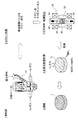
次に、本発明の希土類磁石の製造装置21について図3を用いて説明する。図3は希土類磁石の製造装置21について示した図である。
[Configuration of permanent magnet manufacturing equipment]
Next, the rare earth
図3に示すように希土類磁石の製造装置21は、スラリー供給部22と、振動印加装置23と成形機24を備えた構成を有している。また、この希土類磁石の製造装置21において、スラリー供給部22と振動印加装置23とは、連結管25によって連結されている。また、振動印加装置23からはスラリー供給管26が延びており、これにより振動印加装置23から成形機24にスラリーを供給できるようになっている。
As shown in FIG. 3, the rare earth
また、スラリー供給部22は、攪拌槽31と、この攪拌槽31内に配置された攪拌翼32とを備えている。このスラリー供給部22では、攪拌槽31内に収容された磁石の原料粉末(以下、単に「原料粉末」という)と有機金属化合物(M−(OR)x)を含む溶媒とを、攪拌翼32を回転させることで混合することにより、スラリーを製造することができる。このようなスラリー供給部22としては、例えば、プラネタリーミキサーを適用できる。また、スラリー供給部22の上方には、原料粉末を収容しており攪拌槽31内に原料粉末を投下できる原料粉末供給部33が配置されている。
The slurry supply unit 22 includes a stirring
また、振動印加装置23は、超音波処理槽41と、この超音波処理槽41内に挿入され、当該槽内部のスラリーに振動を伝達するホーン42と、このホーン42の上部に連接された超音波印加部43とを備えている。ここでは、ホーン42及び超音波印加部43が、振動子として機能する。超音波印加部43には、超音波発生器44が接続されており、この超音波発生器44によって超音波印加部43が振動し、ここで発生した振動がホーン42によって槽内のスラリーに伝達される。
The
スラリー供給部22における攪拌槽31と、振動印加装置23における超音波処理槽41とは、連結管25によって連結されている。攪拌槽31内で形成されたスラリーは、この連結管25を通って超音波処理槽41に移動する。この連結管25の途中には、ポンプPが配置されており、このポンプの力によってスラリーが振動印加装置23側に送り出される。連結管25からは、戻り管45が攪拌槽31に戻るように分岐している。例えば、成形機24の稼動時には、成形機24のほうにスラリーが供給されなくなるため、この戻り管45によってスラリーを攪拌槽31内に戻すことができる。
The stirring
また、振動印加装置23における超音波処理槽41には、この槽内からスラリーを取り出すスラリー供給管26が連結されている。このスラリー供給管26は、成形機24まで延びており、成形機24が有するキャビティ等にスラリーを供給できるようになっている。
Further, a
[永久磁石の製造方法]
次に、本発明に係る永久磁石1の製造方法について図4を用いて説明する。図4は本発明に係る永久磁石1の製造方法における製造工程を示した説明図である。
[Permanent magnet manufacturing method]
Next, a method for manufacturing the
先ず、所定分率のR−T−B(例えばNd:26.7wt%、Fe(電解鉄):72.3wt%、B:1.0wt%)からなる、インゴットを製造する。その後、インゴットをスタンプミルやクラッシャー等によって200μm程度の大きさに粗粉砕する。若しくは、インゴットを溶解し、ストリップキャスト法でフレークを作製し、水素解砕法で粗粉化する。 First, an ingot made of R-T-B (for example, Nd: 26.7 wt%, Fe (electrolytic iron): 72.3 wt%, B: 1.0 wt%) in a predetermined fraction is manufactured. Thereafter, the ingot is roughly pulverized to a size of about 200 μm by a stamp mill or a crusher. Alternatively, the ingot is melted, flakes are produced by strip casting, and coarsely pulverized by hydrogen crushing.
次いで、粗粉砕した磁石粉末を、(a)酸素含有量が実質的に0%の窒素ガス、Arガス、Heガスなど不活性ガスからなる雰囲気中、又は(b)酸素含有量が0.0001〜0.5%の窒素ガス、Arガス、Heガスなど不活性ガスからなる雰囲気中で、ジェットミル51により微粉砕し、所定範囲の粒径(例えば0.1μm〜5.0μm)の平均粒径を有する微粉末とする。尚、酸素濃度が実質的に0%とは、酸素濃度が完全に0%である場合に限定されず、微粉の表面にごく僅かに酸化被膜を形成する程度の量の酸素を含有しても良いことを意味する。
Subsequently, the coarsely pulverized magnet powder is either (a) in an atmosphere made of an inert gas such as nitrogen gas, Ar gas, or He gas having substantially 0% oxygen content, or (b) having an oxygen content of 0.0001. Fine particles are pulverized by a
一方で、ジェットミル51で微粉砕された微粉末に添加する有機金属化合物溶液(有機溶媒)を作製する。ここで、有機金属化合物溶液には予めMを含む有機金属化合物を添加し、溶解させる。尚、溶解させる有機金属化合物としては、M−(OR)x(式中、MはNd、Pr、Dy、Tb、V、Mo、Zr、Ta、Ti、W、Nbの内、少なくとも一種を含む。Rは炭素数2〜6のアルキル基のいずれかであり、直鎖でも分枝でも良い。xは任意の整数である。)に該当する有機金属化合物(例えば、ネオジウムエトキシド、ジスプロシウムプロポキシド、テルビウムプロポキシドなど)を用いる。また、溶解させるMを含む有機金属化合物の量は特に制限されないが、焼結後の磁石に対するMの含有量が0.001wt%〜10wt%、好ましくは0.01wt%〜5wt%となる量とするのが好ましい。
On the other hand, an organometallic compound solution (organic solvent) to be added to the fine powder finely pulverized by the
続いて、磁石原料の微粉末と有機金属化合物溶液を作製した後に、これを用い、希土類磁石の製造装置21により成形体を作製する。すなわち、まず、原料粉末を原料粉末供給部33に収容し、ここから攪拌槽31内に投入する。また、これとともに有機金属化合物溶液を攪拌槽31内に添加する。原料粉末と有機金属化合物溶液とはどちらを先に加えてもよい。それから、攪拌翼32を回転させて、原料粉末と有機金属化合物溶液を混合・攪拌して、原料粉末を含むスラリー50を製造する。
Subsequently, a fine powder of a magnet raw material and an organometallic compound solution are prepared, and then a compact is manufactured by using the rare earth
なお、この工程では、有機金属化合物溶液以外に、所望の特性が得られる他の添加剤を更に加えることもできる。添加剤としては、例えば、磁性粉末の分散を促進することができるカチオン系、アニオン系、ベタイン系、非イオン系界面活性剤等の分散剤が挙げられる。このような添加剤は、かかるスラリー製造工程ではなく、後述する混練工程や希釈工程において添加してもよい。 In this step, in addition to the organometallic compound solution, other additives capable of obtaining desired characteristics can be further added. Examples of the additive include dispersants such as cationic, anionic, betaine, and nonionic surfactants that can promote dispersion of the magnetic powder. Such an additive may be added in the kneading step and the diluting step described later, not in the slurry manufacturing step.
スラリー製造工程においては、得られるスラリー50中の原料粉末濃度が好ましくは60〜80質量%、より好ましくは65〜78質量%となるようにする。このような原料粉末濃度を有するスラリー50は、成形機への輸送に好適な流動性を有するものとなる。
In the slurry production step, the raw material powder concentration in the obtained
このスラリー製造工程では、上記の原料粉末濃度を有するスラリー50を得る前に、これよりも高い濃度で混練を行った後(混練工程)に、得られた混練物に有機金属化合物溶液を加えて上記濃度まで希釈するようにしてもよい(希釈工程)。高濃度で混練を行うことによって、原料粉末同士の衝突等が高頻度で生じることとなる。その結果、原料粉末の構成粒子が凝集して2次粒子等を形成している場合は、これを解砕して一次粒子が均一に分散されたスラリー50を得ることが可能となる。このようなスラリー50は、後述する成形時に配向し易く、高配高度を有する希土類磁石を形成することができる。かかる混練時の原料粉末濃度は好ましくは85〜95質量%、より好ましくは88〜94質量%である。なお、混練工程は、スラリー製造工程の前に別途行ってもよい。この場合は、混練により得られた混練物が攪拌槽31内に導入され、溶媒等と混合されてスラリー50となる。
In this slurry production step, before obtaining the
次に、所望の濃度のスラリー50が得られたら、ポンプPを稼動させ、攪拌槽31内のスラリー50を連結管25を通して超音波処理槽41に輸送する(図3参照)。なお、成形機24が稼動中の場合等は、スラリー50の成形機24に向かう流れが止められるので、この間、スラリー50は戻り管45を通って攪拌槽31内に戻されることになる。これによって、スラリー50の循環が保たれ、その良好な分散状態が維持される。
Next, when the
超音波処理槽41に移動したスラリー50には、この槽内に挿入されたホーン42と接触することによって、超音波印加部43で発生した超音波(振動)が印加される。これにより、超音波処理槽41内部でスラリー50が微小に振動し、この振動によってスラリー50中の原料粉末が拡散される。また、例えば、原料粉末の構成粒子が凝集して二次粒子等を形成している場合は、この超音波の印加によって二次粒子等をある程度解砕させ、一次粒子に戻すこともできる。
The
スラリー50に印加する超音波は、原料粉末の分散を良好に生じさせるため、小さい周波数を有していることが好ましい。具体的には、15〜40kHzの周波数を有していると好ましく、15〜20kHzの周波数を有しているとより好ましい。また、このような周波数で超音波を印加する場合、超音波の印加時間は、5〜240秒とすることが好ましく、10〜120秒とすることがより好ましい。印加時間は、スラリー50に確実に超音波を印加するため、超音波処理槽41の容積(cm3)/スラリー流量(cm3/秒)に基づいて求める。この振動印加工程は、スラリー50を加熱しながら行ってもよい。
The ultrasonic wave applied to the
振動の印加によって高分散状態にあるスラリー50は、スラリー供給管26を通って成形機24に投入される。スラリー供給管26は、成形機24が有する金型キャビティ等に直接連結されていてもよく、その先端がキャビティ上方まで延ばされ、この先端部からキャビティ内にスラリー50を投下するような形態であってもよい。そして、スラリー50が供給された成形機24では、磁場を印加しながらスラリー50の成形を行い、これにより成形体が得られる。この成形工程によって、スラリー50中の原料粉末が磁場配向され、所定の配向度を有する成形体が得られる。
The
成形は、例えば、プレス成形により行うことができる。具体的には、スラリー50を成形機24のキャビティ52内に充填した後、充填されたスラリー50を上パンチ53と下パンチ54との間で挟むようにして加圧し、スラリー50中の溶媒を抜き出しながら所定形状に加工する。この際、上パンチ53又は下パンチ54には、流出した溶媒を抜き出すために外部と連通する穴が設けられていてもよい。ただし、磁性粉末の流出が生じないように、パンチ面に布製、紙製等のフィルターを配置するか、或いは、上パンチ53又は下パンチ54の一部の材質を多孔質とすることが好ましい。成形によって得られる成形体の形状は特に制限されず、柱状、平板状、リング状等、所望とする希土類磁石の形状に応じて変更することができる。
The molding can be performed, for example, by press molding. Specifically, after the
成形時の加圧方向61は、磁場の印加方向62と同じとしてもよく、磁場の印加方向と垂直としてもよいが、磁場の印加方向と垂直に加圧を行うと、より優れた磁気特性が得られる傾向にある。また、成形時における磁場強度は、15〜20kOeとすることができ、加圧は0.3〜3ton/cm2とすることができる。さらに、成形時間は、数秒〜数十秒とすることが好ましい。このような条件で磁場中、成形を行うことにより、良好な磁気特性を有する希土類磁石が得られ易い傾向にある。
The
次に、成形機24により湿式状態で圧粉成形された磁石粉末を真空乾燥などで乾燥することにより有機溶媒を揮発させ、成形体71を得る。その後、水素雰囲気において200℃〜900℃、より好ましくは400℃〜900℃(例えば600℃)で数時間(例えば5時間)保持することにより水素中仮焼処理を行う。仮焼中の水素の供給量は5L/minとする。この水素中仮焼処理では、有機金属化合物を熱分解させて、仮焼体中の炭素量を低減させる所謂脱カーボンが行われる。また、水素中仮焼処理は、仮焼体中の炭素量が1000ppm以下、より好ましくは500ppm以下とする条件で行うこととする。それによって、その後の焼結処理で永久磁石1全体を緻密に焼結させることが可能となり、残留磁束密度や保磁力を低下させることが無い。
Next, the organic powder is volatilized by drying the magnet powder compacted in a wet state by the molding
続いて、水素中仮焼処理によって仮焼された成形体71を焼結する焼結処理を行う。焼結処理では、所定の昇温速度で800℃〜1180℃程度まで昇温し、2時間程度保持する。この間は真空焼成となるが真空度としては10−4Torr以下とすることが好ましい。その後冷却し、再び600℃で2時間熱処理を行う。そして、焼結の結果、永久磁石1が製造される。
Then, the sintering process which sinters the molded
上記永久磁石の製造方法により製造された永久磁石1は、超音波分散を行わなかった比較例と比べて、スラリーが良好に分散しており、配高度が高く、高磁気特性を有する希土類磁石が得られることが確認される。
The
以上説明したように、本実施形態に係る永久磁石1及び永久磁石1の製造方法では、粉砕された磁石粉末にM−(OR)x(式中、MはNd、Pr、Dy、Tb、V、Mo、Zr、Ta、Ti、W、Nbの内、少なくとも一種を含む。Rは炭素数2〜6のアルキル基のいずれかであり、直鎖でも分枝でも良い。xは任意の整数である。)で示される有機金属化合物を含む溶媒とを混合したスラリー50を希土類磁石の製造装置21において生成し、その後、成形機24においてキャビティに注入したスラリー50に対して磁場を印加した状態で圧力を加えて成形し、その後に有機溶媒を揮発させて成形体を得る。続いて、成形体を水素雰囲気において200℃〜900℃で数時間保持することにより水素中仮焼処理を行う。続いて、800℃〜1180℃で焼成を行うことによって永久磁石1を製造する。
そして、希土類磁石の製造装置21では、スラリー50を成形に供する前に、振動印加装置23によってスラリー50を振動させる。このようにスラリー50を振動させることで、スラリー50に力学的な力を付与して積極的にスラリー50中の原料粉末を拡散させることができ、これにより成形前のスラリー50の分散性を高めることが可能となる。その結果、スラリー50の流動性を十分に確保できるだけでなく、成形機に送られるスラリー50が均一な原料粉末濃度を有するようになって、個体間でばらつきが少ない磁石の製造が可能となる。また、このように原料粉末が均一に分散されたスラリー50では、成形時における原料粉末の配向が有利となるため、これによって高い配高度を有する磁石を得ることも可能となる。
また、希土類磁石の製造装置21では、スラリー50に接触してスラリー50を振動させる振動子であるホーン42を有するので、スラリー50への振動印加効率が極めて高く、より分散性の高いスラリー50を成形機24に供給することができる。
また、振動印加装置23は、超音波印加装置であるので、超音波のような高エネルギーの振動を印加することによって、スラリー50中の原料粉末の拡散性は一層良好となり、更に分散性に優れるスラリー50を成形機24に供給できるようになる。また、超音波印加装置は、小型でも十分な振動を加えることができるので、装置全体の小型化も図れるようになる。
また、M−(OR)x(式中、MはNd、Pr、Dy、Tb、V、Mo、Zr、Ta、Ti、W、Nbの内、少なくとも一種を含む。Rは炭素数2〜6のアルキル基のいずれかであり、直鎖でも分枝でも良い。xは任意の整数である。)で表わされる有機金属化合物を含む溶媒を添加し、湿式状態で磁石粉末に混合するので、Mを含む有機金属化合物を溶媒中で分散させ、磁石粒子の粒子表面にMを含む有機金属化合物を均一付着することが可能となり、Mを焼結後の希土類磁石の粒界に対して効率よく偏在させることができる。
As described above, in the
Then, in the rare earth
In addition, since the rare earth
Further, since the
M- (OR) x (wherein M includes at least one of Nd, Pr, Dy, Tb, V, Mo, Zr, Ta, Ti, W, and Nb. R has 2 to 6 carbon atoms) And a solvent containing an organometallic compound represented by the following formula is added and mixed with the magnet powder in a wet state. It is possible to disperse organometallic compounds containing Mn in a solvent so that the organometallic compounds containing M are uniformly deposited on the surface of the magnet particles, and the M is unevenly distributed with respect to the grain boundaries of the sintered rare earth magnet. Can be made.
尚、本発明は前記実施例に限定されるものではなく、本発明の要旨を逸脱しない範囲内で種々の改良、変形が可能であることは勿論である。
また、磁石粉末の粉砕条件、混練条件、仮焼条件、焼結条件などは上記実施例に記載した条件に限られるものではない。
また、仮焼処理については省略しても良い。
In addition, this invention is not limited to the said Example, Of course, various improvement and deformation | transformation are possible within the range which does not deviate from the summary of this invention.
Moreover, the pulverization conditions, kneading conditions, calcination conditions, sintering conditions, etc. of the magnet powder are not limited to the conditions described in the above examples.
Moreover, you may abbreviate | omit about a calcination process.
また、振動印加装置23においては超音波の印加によりスラリーを振動させていたが、本発明においてスラリーに印加される振動は、必ずしも超音波に限らず、ある程度の周波数を有する振動であれば、本発明の効果は十分に得られる。スラリーに振動を印加する方法も、振動子の接触には限定されず、例えば、振動子をスラリーが収容された槽や管に接触させ、これらを介してスラリーに振動を印加してもよく、また振動子以外の手段により振動印加装置における処理槽を振動させてもよく、スラリーを成形機に供給する管を振動させてもよい。
Further, in the
また、振動印加装置23においては超音波の印加によりスラリーを振動させていたが、本発明においてスラリーに印加される振動は、必ずしも超音波に限らず、ある程度の周波数を有する振動であれば、本発明の効果は十分に得られる。スラリーに振動を印加する方法も、振動子の接触には限定されず、例えば、振動子をスラリーが収容された槽や管に接触させ、これらを介してスラリーに振動を印加してもよく、また振動子以外の手段により振動印加装置における処理槽を振動させてもよく、スラリーを成形機に供給する管を振動させてもよい。
Further, in the
また、本発明の製造装置又は製造方法は、希土類磁石に限らず、その他の金属磁石やフェライト磁石等、磁性粉末の焼結によって得られる焼結磁石であれば特に制限無く適用することができる。そして、これらの他の磁石の製造に適用した場合であっても、上述した実施形態と同様、分散性が高いままスラリーを成形することができ、高配向を有する磁石を均一に製造することが可能となる。 Further, the production apparatus or production method of the present invention is not limited to rare earth magnets, and can be applied without particular limitation as long as it is a sintered magnet obtained by sintering magnetic powder, such as other metal magnets and ferrite magnets. And even if it is a case where it is a case where it applies to manufacture of these other magnets, a slurry can be shape | molded with high dispersibility similarly to embodiment mentioned above, and the magnet which has high orientation can be manufactured uniformly. It becomes possible.
また、上記実施例では、スラリー50をキャビティ52に注入した状態で磁場を印加して配向を行う構成としているが、本発明はキャビティ52に限定されずに自由な境界条件に対して用いることが可能となる。
Moreover, in the said Example, it is set as the structure which applies a magnetic field in the state which injected the
また、上述した製造方法では、Nd、Pr、Dy、Tb、V、Mo、Zr、Ta、Ti、W、Nbについては、磁石粉末にM−(OR)x(式中、MはNd、Pr、Dy、Tb、V、Mo、Zr、Ta、Ti、W、Nbの内、少なくとも一種を含む。Rは炭素数2〜6のアルキル基のいずれかであり、直鎖でも分枝でも良い。xは任意の整数である。)で示される有機金属化合物を添加することによって、添加する構成としているが、一部については予めインゴットに含める構成としても良い。 In the manufacturing method described above, for Nd, Pr, Dy, Tb, V, Mo, Zr, Ta, Ti, W, and Nb, M- (OR) x (where M is Nd, Pr) , Dy, Tb, V, Mo, Zr, Ta, Ti, W, Nb, and at least one of them, R is an alkyl group having 2 to 6 carbon atoms, and may be linear or branched. x is an arbitrary integer.) By adding the organometallic compound represented by (2), the composition is added. However, a part of the composition may be included in the ingot in advance.
1 永久磁石
11 主相
12 Rリッチ相
21 希土類磁石の製造装置
22 スラリー供給部
23 振動印加装置
24 成形機
42 ホーン
DESCRIPTION OF
Claims (2)
M−(OR)x
(式中、MはNd、Pr、Dy、Tb、V、Mo、Zr、Ta、Ti、W、Nbの内、少なくとも一種を含む。Rは炭素数2〜6のアルキル基のいずれかであり、直鎖でも分枝でも良い。xは任意の整数である。)
で示される有機金属化合物を含む溶媒とを混合したスラリーを製造するスラリー製造工程と、
前記スラリーを振動させる振動印加工程と、
前記振動印加工程後のスラリーを成形して成形体を得る成形工程と、
前記成形体を水素雰囲気で仮焼する工程と、
仮焼された前記成形体を焼成する焼成工程と、
を有することを特徴とする希土類磁石の製造方法。 Raw material powder of rare earth magnet and the following structural formula M- (OR) x
(In the formula, M includes at least one of Nd, Pr, Dy, Tb, V, Mo, Zr, Ta, Ti, W, and Nb. R is any one of alkyl groups having 2 to 6 carbon atoms. It may be linear or branched, and x is an arbitrary integer.)
A slurry production process for producing a slurry mixed with a solvent containing an organometallic compound represented by:
A vibration applying step of vibrating the slurry;
A molding step of molding the slurry after the vibration applying step to obtain a molded body;
Calcination of the molded body in a hydrogen atmosphere;
A firing step of firing the calcined by said molded body,
A method for producing a rare earth magnet, comprising:
The method for producing a rare earth magnet according to claim 1 , wherein, in the vibration applying step, the slurry is vibrated by transmitting ultrasonic waves to the slurry.
Priority Applications (1)
| Application Number | Priority Date | Filing Date | Title |
|---|---|---|---|
| JP2010084275A JP5501831B2 (en) | 2010-03-31 | 2010-03-31 | Rare earth magnet manufacturing method |
Applications Claiming Priority (1)
| Application Number | Priority Date | Filing Date | Title |
|---|---|---|---|
| JP2010084275A JP5501831B2 (en) | 2010-03-31 | 2010-03-31 | Rare earth magnet manufacturing method |
Publications (2)
| Publication Number | Publication Date |
|---|---|
| JP2011216711A JP2011216711A (en) | 2011-10-27 |
| JP5501831B2 true JP5501831B2 (en) | 2014-05-28 |
Family
ID=44946149
Family Applications (1)
| Application Number | Title | Priority Date | Filing Date |
|---|---|---|---|
| JP2010084275A Expired - Fee Related JP5501831B2 (en) | 2010-03-31 | 2010-03-31 | Rare earth magnet manufacturing method |
Country Status (1)
| Country | Link |
|---|---|
| JP (1) | JP5501831B2 (en) |
Families Citing this family (5)
| Publication number | Priority date | Publication date | Assignee | Title |
|---|---|---|---|---|
| CN103128274A (en) * | 2011-12-01 | 2013-06-05 | 四平市北威钼业有限公司 | Ultrasonic homogeneous mixing-proportioning device of multi-element metal powder |
| JP5963870B2 (en) * | 2012-09-06 | 2016-08-03 | 三菱電機株式会社 | Permanent magnet manufacturing method and permanent magnet manufacturing apparatus |
| CN104028744A (en) * | 2014-06-04 | 2014-09-10 | 中磁科技股份有限公司 | Method for raising orientation degree of Nd-Fe-B powder particles |
| KR20180081209A (en) * | 2017-01-06 | 2018-07-16 | 내일테크놀로지 주식회사 | Manufacturing method for 3-D printable radiation shielding body, manufacturing apparatus for radiation shielding body and radiation shielding body |
| CN109192424B (en) * | 2018-08-29 | 2020-06-30 | 宁波招宝磁业有限公司 | Sintered neodymium-iron-boron magnet with ultrahigh coercivity |
Family Cites Families (4)
| Publication number | Priority date | Publication date | Assignee | Title |
|---|---|---|---|---|
| JP4167291B2 (en) * | 2007-02-28 | 2008-10-15 | Tdk株式会社 | Magnet manufacturing apparatus and magnet manufacturing method |
| JP2008251722A (en) * | 2007-03-29 | 2008-10-16 | Tdk Corp | Method and device for manufacturing magnet |
| JP5266522B2 (en) * | 2008-04-15 | 2013-08-21 | 日東電工株式会社 | Permanent magnet and method for manufacturing permanent magnet |
| JP5266523B2 (en) * | 2008-04-15 | 2013-08-21 | 日東電工株式会社 | Permanent magnet and method for manufacturing permanent magnet |
-
2010
- 2010-03-31 JP JP2010084275A patent/JP5501831B2/en not_active Expired - Fee Related
Also Published As
| Publication number | Publication date |
|---|---|
| JP2011216711A (en) | 2011-10-27 |
Similar Documents
| Publication | Publication Date | Title |
|---|---|---|
| JP4923152B2 (en) | Permanent magnet and method for manufacturing permanent magnet | |
| KR101165937B1 (en) | Permanent magnet and manufacturing method for permanent magnet | |
| KR101189840B1 (en) | Permanent magnet and manufacturing method for permanent magnet | |
| JP5501831B2 (en) | Rare earth magnet manufacturing method | |
| JP4865097B2 (en) | Permanent magnet and method for manufacturing permanent magnet | |
| JP2012124496A (en) | Permanent magnet and method for manufacturing permanent magnet | |
| WO2011125588A1 (en) | Permanent magnet and manufacturing method for permanent magnet | |
| JP4865099B2 (en) | Permanent magnet and method for manufacturing permanent magnet | |
| JP2011228659A (en) | Permanent magnet, and method for manufacturing permanent magnet | |
| JP2009032742A (en) | Manufacturing method of rare earth permanent sintered magnet | |
| CN102576590B (en) | Permanent magnet and manufacturing method for permanent magnet | |
| JP5501826B2 (en) | Manufacturing method of rare earth sintered magnet | |
| JP5908247B2 (en) | Method for manufacturing permanent magnet | |
| JP2012253248A (en) | Iron nitride material and method for manufacturing the same | |
| JP4923150B2 (en) | Permanent magnet and method for manufacturing permanent magnet | |
| JP4167291B2 (en) | Magnet manufacturing apparatus and magnet manufacturing method | |
| KR102399418B1 (en) | Manufacturing method of sintered magnetic and sintered magnetic manufactured by the same | |
| JP5501832B2 (en) | Permanent magnet and method for manufacturing permanent magnet | |
| JP5501836B2 (en) | R-Fe-B permanent magnet | |
| JP2011216596A (en) | Permanent magnet and method for manufacturing the same | |
| JP5501827B2 (en) | Permanent magnet and method for manufacturing permanent magnet | |
| JP2011216618A (en) | High-coercive force anisotropic magnet and method for manufacturing the same |
Legal Events
| Date | Code | Title | Description |
|---|---|---|---|
| A621 | Written request for application examination |
Free format text: JAPANESE INTERMEDIATE CODE: A621 Effective date: 20121126 |
|
| A977 | Report on retrieval |
Free format text: JAPANESE INTERMEDIATE CODE: A971007 Effective date: 20131216 |
|
| A131 | Notification of reasons for refusal |
Free format text: JAPANESE INTERMEDIATE CODE: A131 Effective date: 20131224 |
|
| A521 | Written amendment |
Free format text: JAPANESE INTERMEDIATE CODE: A523 Effective date: 20140121 |
|
| TRDD | Decision of grant or rejection written | ||
| A01 | Written decision to grant a patent or to grant a registration (utility model) |
Free format text: JAPANESE INTERMEDIATE CODE: A01 Effective date: 20140304 |
|
| A61 | First payment of annual fees (during grant procedure) |
Free format text: JAPANESE INTERMEDIATE CODE: A61 Effective date: 20140312 |
|
| R150 | Certificate of patent or registration of utility model |
Ref document number: 5501831 Country of ref document: JP Free format text: JAPANESE INTERMEDIATE CODE: R150 |
|
| R250 | Receipt of annual fees |
Free format text: JAPANESE INTERMEDIATE CODE: R250 |
|
| R250 | Receipt of annual fees |
Free format text: JAPANESE INTERMEDIATE CODE: R250 |
|
| LAPS | Cancellation because of no payment of annual fees |