JP5500935B2 - Furnace cleaning device - Google Patents
Furnace cleaning device Download PDFInfo
- Publication number
- JP5500935B2 JP5500935B2 JP2009230830A JP2009230830A JP5500935B2 JP 5500935 B2 JP5500935 B2 JP 5500935B2 JP 2009230830 A JP2009230830 A JP 2009230830A JP 2009230830 A JP2009230830 A JP 2009230830A JP 5500935 B2 JP5500935 B2 JP 5500935B2
- Authority
- JP
- Japan
- Prior art keywords
- cover member
- air
- cleaning device
- furnace
- furnace cleaning
- Prior art date
- Legal status (The legal status is an assumption and is not a legal conclusion. Google has not performed a legal analysis and makes no representation as to the accuracy of the status listed.)
- Active
Links
Images


Landscapes
- Coke Industry (AREA)
Description
本発明は、コークス炉の上面に形成された石炭の装入口を掃除するための炉上クリーニング装置に関するものである。 The present invention relates to an in-furnace cleaning device for cleaning a coal inlet formed on an upper surface of a coke oven.
炭化室内で石炭を乾留することによりコークスを生成するためのコークス炉には、炭化室内に石炭を装入するための装入口が形成されている。この装入口は、通常、コークス炉の上面に形成されており、コークス炉の上方を移動する装入車によって、上方から装入口を介して炭化室内に石炭が装入されるようになっている。 A coke oven for producing coke by dry distillation of coal in the carbonization chamber is formed with an inlet for charging the coal into the carbonization chamber. This charging port is normally formed on the upper surface of the coke oven, and coal is charged into the carbonization chamber from above through the charging port by a charging vehicle that moves above the coke oven. .
コークス炉には多数の装入口が形成されており、装入車が各装入口に移動して順次に石炭を装入する。各装入口に石炭を装入する際には、各装入口を塞いでいる蓋を取り外して石炭を装入した後、当該装入口を再び蓋で塞ぐといった作業が、各装入口に装入車が移動する度に行われる。 A large number of inlets are formed in the coke oven, and a charging vehicle moves to each inlet to sequentially charge coal. When charging coal into each charging port, the work of removing the lid that plugs each charging port, charging the coal, and then plugging the charging port again with the lid is carried into each charging port. Performed each time the moves.
装入口から炭化室内に石炭を装入する際には、装入口の周囲にも石炭が落下してしまう場合がある。このような装入口の周囲に落下した石炭をそのままにしておくのは好ましくないため、装入口の周囲を含むコークス炉の上面全体を掃除するための炉上クリーニング装置が一般的に使用されている(例えば、特許文献1〜6参照)。 When charging coal from the charging port into the carbonization chamber, the coal may also fall around the charging port. Since it is not preferable to leave the coal that has fallen around the charging inlet as such, an in-furnace cleaning device for cleaning the entire upper surface of the coke oven including the surroundings of the charging inlet is generally used. (For example, refer to Patent Documents 1 to 6).
図5は、従来の炉上クリーニング装置100の一例について説明するための概略平面図である。コークス炉1の上面2には、円形の装入口3が複数形成されており、これらの装入口3から下方の炭化室内に石炭を装入することができるようになっている。この図5では、1つの炭化室について1列に並べて複数設けられた装入口3が示されているが、コークス炉1には、図5に矢印Aで示した幅方向に並べて複数の炭化室が設けられており、各炭化室について複数の装入口3が設けられている。
FIG. 5 is a schematic plan view for explaining an example of a conventional in-furnace cleaning apparatus 100. A plurality of
コークス炉1の上面2には、幅方向Aに沿って延びる複数のレール4が設けられており、これらのレール4上を装入車(図示せず)が幅方向Aに移動できるようになっている。装入車は、レール4に沿って各炭化室の上方に順次に移動し、各炭化室に設けられた複数の装入口3から石炭を装入する。このように各装入口3から石炭を装入する際、装入口3の周囲に落下した粉状の石炭(落炭)を除去するため、この例では、落炭を吸引するための炉上クリーニング装置100が、幅方向Aに直交する前後方向Bに沿って移動可能に設けられている。炉上クリーニング装置100は、通常、各装入口3を蓋6で塞いだ状態で使用される。
The
この炉上クリーニング装置100は、一般家庭で使用される掃除機の吸引口と同様、幅方向Aに延びる細長い吸引口を有しており、当該吸引口から落炭を吸引することができる。炉上クリーニング装置100の吸引口は、装入口3の内径よりも長く形成されている。したがって、炉上クリーニング装置100を炭化室の上方に位置合わせして前後方向Bに移動させることにより、各炭化室に1列に並べて形成された複数の装入口3上を順次に移動させることができる。これにより、図5に一点鎖線で示すように、各装入口3の周囲を含む領域C上の落炭が炉上クリーニング装置100により吸引される。
This on-furnace cleaning apparatus 100 has a long and narrow suction port extending in the width direction A, similar to the suction port of a vacuum cleaner used in general households, and can suck charcoal from the suction port. The suction port of the on-furnace cleaning device 100 is formed longer than the inner diameter of the
しかしながら、図5に示すような従来の方法では、炉上クリーニング装置100で吸引しきれずに残った落炭が、炉上クリーニング装置100の移動軌跡(前後方向B)に対して直交方向(幅方向A)に延びるレール4の側方の領域Dに堆積するといった問題があった。 However, in the conventional method as shown in FIG. 5, the falling charcoal remaining without being sucked by the in-furnace cleaning apparatus 100 is perpendicular to the movement locus (front-rear direction B) of the in-furnace cleaning apparatus 100 (width direction). There was a problem of depositing in a region D on the side of the rail 4 extending to A).
また、コークス炉1の上面2には、レール4以外にも、炉上クリーニング装置100の移動軌跡に交差するダクトなどが設けられている場合がある。図5の例では、各炭化室の温度を測定するために使用される測温ケーブルが、コークス炉1の上面2を幅方向Aに延びる測温ケーブルダクト5内に収容されており、当該測温ケーブルダクト5の側方の領域Eにも落炭が堆積する場合がある。
In addition to the rails 4, a duct that intersects the movement trajectory of the furnace cleaning device 100 may be provided on the
本発明は、上記実情に鑑みてなされたものであり、コークス炉の上面の落炭をより良好に吸引することができる炉上クリーニング装置を提供することを目的とする。 This invention is made | formed in view of the said situation, and it aims at providing the furnace cleaning apparatus which can attract | suck the falling coal of the upper surface of a coke oven more favorably.
本発明に係る炉上クリーニング装置は、コークス炉の上面に形成された石炭の装入口を掃除するための炉上クリーニング装置であって、前記装入口全体を上方から覆うことができるカバー部材と、前記カバー部材内の空気を吸引する吸引機構とを備えたことを特徴とする。 An in-furnace cleaning device according to the present invention is an in-furnace cleaning device for cleaning a coal charging port formed on an upper surface of a coke oven, and can cover the entire charging port from above, And a suction mechanism for sucking air in the cover member.
このような構成によれば、装入口全体をカバー部材により上方から覆い、そのカバー部材内の空気を吸引機構で吸引することにより、装入口の周囲の落炭を一度に吸引することができる。これにより、コークス炉の上面の落炭を良好に吸引することができるので、落炭がコークス炉の上面に堆積することもない。 According to such a configuration, the entire inlet can be covered with the cover member from above, and the falling carbon around the inlet can be sucked at a time by sucking the air in the cover member with the suction mechanism. Thereby, since the falling coal of the upper surface of a coke oven can be attracted | sucked favorably, falling coal does not accumulate on the upper surface of a coke oven.
本発明に係る炉上クリーニング装置は、前記カバー部材内に空気を送る送風機構を備えたことを特徴とする。 The on-furnace cleaning apparatus according to the present invention is characterized by including a blower mechanism for sending air into the cover member.
このような構成によれば、送風機構からカバー部材内に空気を送ることにより、カバー部材内で落炭を巻き上げ、その落炭を吸引機構により吸引することができる。カバー部材が装入口全体を覆っているので、カバー部材内で巻き上げられた落炭がカバー部材の外に出るのを防止することができ、さらに良好に落炭を吸引することができる。 According to such a configuration, by sending air from the blower mechanism into the cover member, it is possible to wind up the charcoal in the cover member and suck the charcoal by the suction mechanism. Since the cover member covers the entire loading port, it is possible to prevent the falling charcoal rolled up in the covering member from coming out of the covering member, and to suck the falling charcoal more satisfactorily.
本発明に係る炉上クリーニング装置は、前記送風機構が、前記カバー部材の中央部において、前記装入口の上方から下方に向かって空気を送る第1送風機構を有することを特徴とする。 The on-furnace cleaning device according to the present invention is characterized in that the air blowing mechanism has a first air blowing mechanism that sends air from the upper side to the lower side of the loading port at a central portion of the cover member.
このような構成によれば、第1送風機構から空気を送ることにより、カバー部材の中央部に位置する装入口の周囲の落炭を良好に巻き上げ、吸引機構により吸引することができる。 According to such a structure, by sending air from the 1st ventilation mechanism, the falling charcoal around the charging inlet located in the center part of a cover member can be wound up favorably, and can be attracted | sucked by a suction mechanism.
本発明に係る炉上クリーニング装置は、前記送風機構が、前記カバー部材の周縁部において、前記装入口の外側から前記装入口側に向かって空気を送る第2送風機構を有することを特徴とする。 The on-furnace cleaning device according to the present invention is characterized in that the air blowing mechanism has a second air blowing mechanism that sends air from the outside of the charging port toward the charging port side at the peripheral edge of the cover member. .
このような構成によれば、第1送風機構により巻き上げられた落炭のうち、吸引されずに装入口の外側に移動する落炭を、第2送風機構からの空気によって巻き上げ、吸引機構により吸引することができる。 According to such a configuration, among the falling coal that has been wound up by the first blowing mechanism, the falling coal that moves to the outside of the inlet without being sucked is wound up by the air from the second blowing mechanism and sucked by the suction mechanism. can do.
本発明に係る炉上クリーニング装置は、前記カバー部材を上下方向にスライド可能に支持する支持部材を備えたことを特徴とする。 The furnace cleaning apparatus according to the present invention includes a support member that supports the cover member so as to be slidable in the vertical direction.
このような構成によれば、カバー部材を上方から下方に移動させて装入口を覆う際に、コークス炉の上面に当接したカバー部材を上方向にスライドさせて、衝撃を和らげることができる。これにより、カバー部材をコークス炉の上面に密着させた状態で吸引を行うことができるので、コークス炉の上面の落炭をさらに良好に吸引することができる。 According to such a configuration, when the cover member is moved from the upper side to the lower side to cover the charging port, the cover member that is in contact with the upper surface of the coke oven can be slid upward to reduce the impact. Thereby, since suction can be performed in a state where the cover member is in close contact with the upper surface of the coke oven, the charcoal on the upper surface of the coke oven can be further improved.
本発明に係る炉上クリーニング装置は、前記カバー部材と前記支持部材とが、弾性部材を装着したスライド軸で連結されていることを特徴とする。 The on-furnace cleaning device according to the present invention is characterized in that the cover member and the support member are connected by a slide shaft on which an elastic member is mounted.
このような構成によれば、コークス炉の上面にカバー部材が当接する際の衝撃を弾性部材により効果的に和らげることができる。 According to such a configuration, the impact when the cover member comes into contact with the upper surface of the coke oven can be effectively reduced by the elastic member.
本発明に係る炉上クリーニング装置は、前記カバー部材には、その中央部に開口が形成され、当該開口内に前記支持部材が挿通されており、前記カバー部材と前記支持部材との間の隙間から、外部の空気を前記カバー部材内に導入することができることを特徴とする。 In the in-furnace cleaning apparatus according to the present invention, the cover member has an opening formed in a central portion thereof, the support member is inserted into the opening, and a gap between the cover member and the support member The outside air can be introduced into the cover member.
このような構成によれば、カバー部材と支持部材との間の隙間から外部の空気がカバー部材内に導入されるので、カバー部材をコークス炉の上面に密着させた状態で吸引を行った場合であっても、カバー部材内の圧力低下を防止することができ、良好に吸引を行うことができる。 According to such a configuration, since external air is introduced into the cover member from the gap between the cover member and the support member, suction is performed with the cover member in close contact with the upper surface of the coke oven. Even so, pressure drop in the cover member can be prevented, and suction can be performed satisfactorily.
本発明に係る炉上クリーニング装置は、前記カバー部材が、前記支持部材が挿通される筒部と、当該筒部の下端縁から外側に張り出したフード部とを有し、前記吸引機構が、前記筒部の外周面に取り付けられた吸引ダクトを介して、前記カバー部材内の空気を吸引することを特徴とする。 In the in-furnace cleaning device according to the present invention, the cover member includes a cylinder part through which the support member is inserted, and a hood part protruding outward from a lower end edge of the cylinder part, and the suction mechanism includes the The air in the cover member is sucked through a suction duct attached to the outer peripheral surface of the cylindrical portion.
このような構成によれば、フード部により装入口の周囲を良好に覆うことができるとともに、フード部よりも中央側に位置する筒部の外周面に取り付けられた吸引ダクトを介して、カバー部材内の空気を良好に吸引することができる。 According to such a configuration, the cover member can be satisfactorily covered by the hood portion, and the cover member can be connected via the suction duct attached to the outer peripheral surface of the cylindrical portion located on the center side of the hood portion. The air inside can be sucked well.
本発明によれば、装入口全体をカバー部材により上方から覆い、そのカバー部材内の空気を吸引機構で吸引することにより、装入口の周囲の落炭を一度に吸引することができるので、コークス炉の上面の落炭をより良好に吸引することができる。 According to the present invention, since the entire charging port is covered from above by the cover member, and the air in the cover member is sucked by the suction mechanism, the falling charcoal around the charging port can be sucked at a time. The falling charcoal on the upper surface of the furnace can be sucked better.
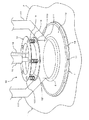
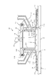
図1は、本発明の一実施形態に係る炉上クリーニング装置10の外観構成を示した斜視図である。図2は、図1の炉上クリーニング装置10の断面図である。この炉上クリーニング装置10は、コークス炉1の上面2に形成された石炭の装入口3を掃除するためのものであり、装入口3全体を上方から覆うことができるカバー部材11と、カバー部材11を上下方向にスライド可能に支持する支持部材12とを備えている。炉上クリーニング装置10は、通常、各装入口3を蓋6で塞いだ状態で使用される。
FIG. 1 is a perspective view showing an external configuration of a
カバー部材11は、支持部材12が挿通される円筒部111と、円筒部111の下端縁から外側に張り出したフード部112と、円筒部111の上端縁から外側に張り出したフランジ部113とを有する。円筒部111の内径は装入口3の内径よりも小さく、当該円筒部111が装入口3の上方に位置するように配置される。フード部112は、円筒部111が延びる方向に対してほぼ直交方向、すなわちほぼ水平方向に延びるが、外周側が徐々に下方に向かうように若干傾斜している。これにより、カバー部材11をコークス炉1の上面2に当接させた状態では、フード部112の外周縁が上面2に当接し、当該外周縁よりも内側に空間が形成されるようになっている。
The
支持部材12は、カバー部材11の円筒部111に挿通される円筒部121と、円筒部121の上端縁から外側に張り出したフランジ部122とを有する。カバー部材11の円筒部111は、その内周面が支持部材12の円筒部121の外径よりも大きい円形の開口114を形成している。この開口114内に支持部材12の円筒部121が挿通されることにより、支持部材12の円筒部121の外周面が、カバー部材11の円筒部111の内周面に対して所定間隔を空けて対向する。
The
カバー部材11のフランジ部113及び支持部材12のフランジ部122は、それぞれ水平方向に延びており、複数のスライド軸13を介して互いに上下方向にスライド可能な状態で取り付けられている。各スライド軸13は、弾性部材としての圧縮ばね14に挿通され、これにより、カバー部材11のフランジ部113と支持部材12のフランジ部122とが、圧縮ばね14を装着したスライド軸13で連結されている。ただし、弾性部材は圧縮ばね14に限らず、ゴムなどの他の部材により構成されていてもよい。
The
上記のように、支持部材12によりカバー部材11を上下方向にスライド可能に支持する構成によれば、カバー部材11を上方から下方に移動させて装入口3を覆う際に、コークス炉1の上面2に当接したカバー部材11を上方向にスライドさせて、衝撃を和らげることができる。これにより、カバー部材11をコークス炉1の上面2に密着させた状態で吸引を行うことができるので、コークス炉1の上面2の落炭を良好に吸引することができる。また、カバー部材11と支持部材12とが、弾性部材(圧縮ばね14)を装着したスライド軸13で連結されることにより、コークス炉1の上面2にカバー部材11が当接する際の衝撃をより効果的に和らげることができる。
As described above, according to the configuration in which the
支持部材12の円筒部121は、その上面が閉塞されており、当該上面に支持部材12を支持するための支持アーム15が固定されるとともに、円筒部121内に空気を送るための送風管16が固定されている。この送風管16は、カバー部材11の中央部において、装入口3の上方から下方に向かって空気を送る第1送風機構を構成している。送風管16から支持部材12の円筒部121内に送り込まれた空気は、当該円筒部121内を下方に向かって流れ、当該円筒部121の下端部から装入口3を塞ぐ蓋6の上面に吹き付けられて外側(装入口3の周囲側)に向かう。
The upper surface of the
ただし、第1送風機構は、上記のような円筒部121の上面に固定された1つの送風管16により構成されるものに限らず、例えば複数の送風管16により構成されるものであってもよい。また、送風管16が円筒部121の上面に固定された構成に限らず、側面に固定された構成であってもよいし、支持部材12が他の形状を有する場合には、その形状に応じて任意の位置に送風管16を固定することができる。また、送風管16は、支持部材12に取り付けられた構成に限らず、例えばカバー部材11の中央部に直接取り付けられた構成であってもよいし、他の部材を介して取り付けられた構成であってもよい。
However, the first blower mechanism is not limited to the one constituted by the
カバー部材11の円筒部111は、それぞれ円筒形状からなる外壁115と内壁116とが、互いに間隔を空けた状態で結合された二重構造となっている。外壁115には、複数の吸引ダクト117が結合されており、外壁115と内壁116との間に形成された流路118を介して、カバー部材11内の空気を吸引ダクト117に吸引することができるようになっている。これらの吸引ダクト117及び流路118は、カバー部材11内の空気を吸引する吸引機構を構成している。
The
ただし、吸引機構は、上記のような複数の吸引ダクト117及び流路118により構成されるものに限らず、例えば吸引ダクト117が1つだけ設けられた構成であってもよいし、流路118が省略されて、カバー部材11内の空気が吸引ダクト117に直接吸引されるような構成であってもよい。また、吸引ダクト117がカバー部材11の円筒部111に固定された構成に限らず、カバー部材11が他の形状を有する場合には、その形状に応じて任意の位置に吸引ダクト117を固定することができる。
However, the suction mechanism is not limited to the one constituted by the plurality of
外壁115は、その下端側が徐々に外側に広がるような傾斜面115Aとなっており、その下端縁がフード部112に連通している。内壁116も、その下端縁が徐々に外側に広がるような傾斜面116Aとなっており、当該傾斜面116Aが外壁115の傾斜面115Aに対して間隔を空けて平行に延びている。内壁116の傾斜面116Aは、その下端縁が、装入口3の周縁部に対して上方に離間した位置に対向するように形成されている。これにより、内壁116の傾斜面116Aの下端縁が、対向する外壁115との間に吸引口119を形成し、当該吸引口119から装入口3の周縁部上の空気を流路118内に吸引することができるようになっている。また、内壁116の傾斜面116Aは、送風管16から支持部材12の円筒部121内に送り込まれた空気を、円筒部121の下端部から外側(装入口3の周囲側)へと円滑に導くためのガイド部としても機能する。
The
カバー部材11のフード部112の周縁部には、装入口3の外側から装入口3側に向かって空気を送るための送風管17が固定されている。この例では、複数の送風管17がフード部112に対して周方向に等間隔で設けられており、フード部112の周縁部に沿って設けられた円環状の接続管18を介して、複数の送風管17が連通されている。これにより、接続管18に空気を送り込むことによって、当該接続管18を介して複数の送風管17から空気を送り出すことができる。これらの複数の送風管17及び接続管18は、カバー部材11の周縁部において、装入口3の外側から装入口3側に向かって空気を送る第2送風機構を構成している。
A
ただし、第2送風機構は、上記のような複数の送風管17及び接続管18により構成されるものに限らず、例えば送風管17が1つだけ設けられた構成であってもよいし、接続管18が省略されて、各送風管17に直接空気が送り込まれるような構成であってもよい。また、送風管17がカバー部材11のフード部112に固定された構成に限らず、カバー部材11が他の形状を有する場合には、その形状に応じて任意の位置に送風管17を固定することができる。第1送風機構及び第2送風機構は、カバー部材11内に空気を送る送風機構を構成しているが、いずれか一方を省略することも可能であるし、他の送風機構をさらに備えた構成とすることも可能である。
However, the second air blowing mechanism is not limited to the one constituted by the plurality of
本実施形態では、装入口3全体をカバー部材11により上方から覆い、そのカバー部材11内の空気を吸引機構で吸引することにより、装入口3の周囲の落炭を一度に吸引することができる。これにより、コークス炉1の上面2の落炭を良好に吸引することができるので、落炭がコークス炉1の上面2に堆積することもない。
In the present embodiment, the
また、本実施形態では、送風機構からカバー部材11内に空気を送ることにより、カバー部材11内で落炭を巻き上げ、その落炭を吸引機構により吸引することができる。カバー部材11が装入口3全体を覆っているので、カバー部材11内で巻き上げられた落炭がカバー部材11の外に出るのを防止することができ、さらに良好に落炭を吸引することができる。
Moreover, in this embodiment, by sending air into the
特に、カバー部材11の中央部において、装入口3の上方から下方に向かって空気を送る第1送風機構により、カバー部材11の中央部に位置する装入口3の周囲の落炭を良好に巻き上げ、吸引機構により吸引することができる。また、第1送風機構により巻き上げられた落炭のうち、吸引されずに装入口3の外側に移動する落炭を、カバー部材11の周縁部において、装入口3の外側から装入口3側に向かって空気を送る第2送風機構により巻き上げ、吸引機構により吸引することができる。
In particular, in the central part of the
また、本実施形態では、フード部112により装入口3の周囲を良好に覆うことができるとともに、フード部112よりも中央側に位置する円筒部111の外周面に取り付けられた吸引ダクト117を介して、カバー部材11内の空気を良好に吸引することができる。
Further, in the present embodiment, the periphery of the
本実施形態では、吸引ダクト117を介してカバー部材11内の空気が吸引される際、カバー部材11の円筒部111と支持部材12の円筒部121との隙間から、カバー部材11内に外部の空気を導入することができるようになっている。これにより、カバー部材11をコークス炉1の上面2に密着させた状態で吸引を行った場合であっても、カバー部材11内の圧力低下を防止することができ、良好に吸引を行うことができる。
In the present embodiment, when the air in the
図3は、炉上クリーニング装置10の使用態様について説明するための概略断面図である。また、図4は、炉上クリーニング装置10の使用態様について説明するための概略平面図である。コークス炉1の上面2には、円形の装入口3が複数形成されており、これらの装入口3から下方の炭化室内に石炭を装入することができるようになっている。図3及び図4では、1つの炭化室について1列に並べて複数設けられた装入口3が示されているが、コークス炉1には、図4に矢印Aで示した幅方向に並べて複数の炭化室が設けられており、各炭化室について複数の装入口3が設けられている。
FIG. 3 is a schematic cross-sectional view for explaining a usage mode of the
コークス炉1の上面2には、幅方向Aに沿って延びる複数のレール4が設けられており、これらのレール4上を装入車(図示せず)が幅方向Aに移動できるようになっている。装入車は、レール4に沿って各炭化室の上方に順次に移動し、各炭化室に設けられた複数の装入口3から石炭を装入する。このように各装入口3から石炭を装入する際、装入口3の周囲に落下した石炭(落炭)を除去するため、落炭を吸引するための炉上クリーニング装置10が、幅方向Aに直交する前後方向Bに沿って移動可能に設けられている。炉上クリーニング装置10は、各装入口3を蓋6で塞いだ状態で使用される。
The
この例では、2つの炉上クリーニング装置10が、それぞれを支持する支持アーム15を介して互いに連結されており、これにより、2つの炉上クリーニング装置10を一体的に移動させることができるようになっている。1つの炉上クリーニング装置10を個別に移動させることも可能であるが、炉上クリーニング装置10の移動方向(前後方向B)に並ぶ複数の装入口3間の間隔が一定である場合には、2つ以上の炉上クリーニング装置10を一体的に移動させることにより、複数の装入口3に対して一度に掃除を行うことができる。
In this example, two in-
炉上クリーニング装置10は、支持アーム15を介して連結された駆動機構20により駆動される。この駆動機構20により、炉上クリーニング装置10を幅方向Aに移動させて所望の炭化室の上方に移動させた後、その上方で炉上クリーニング装置10を前後方向Bに移動させ、当該炭化室に設けられた各装入口3上に炉上クリーニング装置10を順次に降下させて掃除を行うことができる。この駆動機構20に対する制御は、コンピュータなどで構成される制御部21により行われる。制御部21は、駆動機構20に対する制御だけでなく、炉上クリーニング装置10に備えられた吸引機構及び送風機構などに対する制御も行う。
The in-
吸引機構及び送風機構は、任意の態様により動作させることができるが、一例として、吸引機構による吸引風量は80m3/min、送風機構による送風圧力は0.3MPa〜0.5MPaとすることができる。また、第1送風機構を構成する送風管16からの送風のタイミングと、第2送風機構を構成する送風管17からの送風のタイミングとをずらすことも可能である。この場合、装入口3上で炉上クリーニング装置10を降下させてカバー部材11により装入口3を覆い、再び炉上クリーニング装置10を上昇させるといった動作を2回行い、それぞれの動作の際に送風管16又は送風管17の一方から送風するような構成とすることもできる。例えば、1回目に炉上クリーニング装置10が装入口3を覆った際には、送風管16から1秒間送風を行い、2回目に炉上クリーニング装置10が装入口3を覆った際には、送風管17から1秒間送風を行うといった構成であってもよい。なお、吸引機構による吸引は、炉上クリーニング装置10が降下するのと同時に開始されることが好ましい。
The suction mechanism and the blower mechanism can be operated in any manner, but as an example, the suction air volume by the suction mechanism can be 80 m 3 / min, and the blower pressure by the blower mechanism can be 0.3 MPa to 0.5 MPa. . Moreover, it is also possible to shift the timing of the ventilation from the ventilation pipe |
本実施形態では、図4に一点鎖線で示すように、各装入口3の周囲の領域Fについてのみ炉上クリーニング装置10により落炭を良好に吸引することができる。
In the present embodiment, as shown by a one-dot chain line in FIG. 4, the in-car removal can be satisfactorily sucked by the in-
また、各装入口3の周囲の領域Fについてのみ落炭を吸引するような構成を採用することにより、雨天の場合であっても良好に落炭を吸引することができる。雨天の場合、各装入口3の周囲の領域Fでは比較的高温となるため、落炭の湿度が低く良好に吸引することができる。
Moreover, by adopting a configuration in which the falling coal is sucked only in the region F around each
以上の実施形態では、カバー部材11が円筒部111及びフード部112を備えた構成について説明したが、カバー部材11の形状としては、装入口3全体を上方から覆うことができるような形状であれば、他のあらゆる形状を採用することができる。また、装入口3は、円形に限らず、四角形などの他の形状であってもよい。この場合、カバー部材11の形状も装入口3の形状に合わせて任意の形状とすることができる。
In the above embodiment, the configuration in which the
1 コークス炉
2 上面
3 装入口
4 レール
5 測温ケーブルダクト
6 蓋
10 炉上クリーニング装置
11 カバー部材
12 支持部材
13 スライド軸
14 圧縮ばね
15 支持アーム
16 送風管
17 送風管
18 接続管
20 駆動機構
21 制御部
111 円筒部
112 フード部
113 フランジ部
114 開口
115 外壁
116 内壁
117 吸引ダクト
118 流路
119 吸引口
121 円筒部
122 フランジ部
DESCRIPTION OF SYMBOLS 1
Claims (7)
前記装入口全体を上方から覆うことができるカバー部材と、
前記カバー部材内の空気を吸引する吸引機構と、
前記カバー部材内に空気を送る送風機構と、を備えたことを特徴とする炉上クリーニング装置。 An on-furnace cleaning device for cleaning a coal charging port formed on the upper surface of a coke oven,
A cover member capable of covering the entire loading port from above;
A suction mechanism for sucking air in the cover member ;
An on-furnace cleaning device comprising: a blower mechanism for sending air into the cover member .
前記カバー部材と前記支持部材との間の隙間から、外部の空気を前記カバー部材内に導入することができることを特徴とする請求項4又は5に記載の炉上クリーニング装置。 The cover member has an opening at the center thereof, and the support member is inserted into the opening.
The in-furnace cleaning device according to claim 4 or 5 , wherein external air can be introduced into the cover member from a gap between the cover member and the support member.
前記吸引機構は、前記筒部の外周面に取り付けられた吸引ダクトを介して、前記カバー部材内の空気を吸引することを特徴とする請求項4〜6のいずれかに記載の炉上クリーニング装置。 The cover member has a cylindrical portion through which the support member is inserted, and a hood portion that protrudes outward from a lower end edge of the cylindrical portion,
The in-furnace cleaning device according to any one of claims 4 to 6 , wherein the suction mechanism sucks air in the cover member through a suction duct attached to an outer peripheral surface of the cylindrical portion. .
Priority Applications (1)
| Application Number | Priority Date | Filing Date | Title |
|---|---|---|---|
| JP2009230830A JP5500935B2 (en) | 2009-10-02 | 2009-10-02 | Furnace cleaning device |
Applications Claiming Priority (1)
| Application Number | Priority Date | Filing Date | Title |
|---|---|---|---|
| JP2009230830A JP5500935B2 (en) | 2009-10-02 | 2009-10-02 | Furnace cleaning device |
Publications (2)
| Publication Number | Publication Date |
|---|---|
| JP2011079881A JP2011079881A (en) | 2011-04-21 |
| JP5500935B2 true JP5500935B2 (en) | 2014-05-21 |
Family
ID=44074273
Family Applications (1)
| Application Number | Title | Priority Date | Filing Date |
|---|---|---|---|
| JP2009230830A Active JP5500935B2 (en) | 2009-10-02 | 2009-10-02 | Furnace cleaning device |
Country Status (1)
| Country | Link |
|---|---|
| JP (1) | JP5500935B2 (en) |
Family Cites Families (3)
| Publication number | Priority date | Publication date | Assignee | Title |
|---|---|---|---|---|
| JPS5976541U (en) * | 1982-11-17 | 1984-05-24 | 新日鐵化学株式会社 | Coke oven furnace cleaning equipment |
| JPH0443Y2 (en) * | 1985-08-27 | 1992-01-06 | ||
| JP4122885B2 (en) * | 2002-07-31 | 2008-07-23 | 住友金属工業株式会社 | Coke oven furnace cleaner |
-
2009
- 2009-10-02 JP JP2009230830A patent/JP5500935B2/en active Active
Also Published As
| Publication number | Publication date |
|---|---|
| JP2011079881A (en) | 2011-04-21 |
Similar Documents
| Publication | Publication Date | Title |
|---|---|---|
| CN1853549A (en) | Automatic cleaning device | |
| CN101049218A (en) | Robot cleaner system having robot cleaner and docking station | |
| KR101556401B1 (en) | Movable collecting dust apparatus | |
| CN110497457A (en) | A kind of toy production paper tube process equipment | |
| CN201632453U (en) | Dust removing device for semiconductor element | |
| KR101282328B1 (en) | dust collecting apparatus of cokes oven pusher car | |
| EP1808114A3 (en) | Suction nozzle for vacuum cleaner | |
| JP2011079881A (en) | Cleaning apparatus on oven | |
| CN219313990U (en) | SCR catalyst grabbing mechanism with ash removal function | |
| CN110805919B (en) | Slag discharging device for flue | |
| CN204429827U (en) | For the fume extractor of lead pan | |
| JP4122885B2 (en) | Coke oven furnace cleaner | |
| CN102847387A (en) | Mobile line spray dust cleaner | |
| CN112122297A (en) | Cutting waste collection device and cutting equipment | |
| CN207432027U (en) | A kind of cleaning chamber for shot-blasting machine | |
| CN111717506B (en) | Plastic sucking disc for touch screen processing transfer, cleaning equipment and cleaning method | |
| JP3978290B2 (en) | Cleaner for cleaning side rails on coke oven furnace | |
| CN210138901U (en) | Dust removal device for cartridges and cartridge conveying system with the same | |
| CN211093748U (en) | Cleaning equipment and dust collector | |
| CN220617655U (en) | Dust collection device for blanking dish of lime kiln | |
| CN114212535A (en) | Clamping equipment for LED perspective die pressing feeding | |
| CN216827624U (en) | Clean check out test set of computer fan accessory | |
| CN202497079U (en) | Filter screen automatic dust cleaning type industrial dust collector | |
| CN210192767U (en) | Automatic tube loading mechanism | |
| CN215745214U (en) | Sagger semi-manufactured goods rack for dust removal |
Legal Events
| Date | Code | Title | Description |
|---|---|---|---|
| A621 | Written request for application examination |
Free format text: JAPANESE INTERMEDIATE CODE: A621 Effective date: 20120907 |
|
| A977 | Report on retrieval |
Free format text: JAPANESE INTERMEDIATE CODE: A971007 Effective date: 20140117 |
|
| A131 | Notification of reasons for refusal |
Free format text: JAPANESE INTERMEDIATE CODE: A131 Effective date: 20140121 |
|
| A521 | Request for written amendment filed |
Free format text: JAPANESE INTERMEDIATE CODE: A523 Effective date: 20140210 |
|
| TRDD | Decision of grant or rejection written | ||
| A01 | Written decision to grant a patent or to grant a registration (utility model) |
Free format text: JAPANESE INTERMEDIATE CODE: A01 Effective date: 20140226 |
|
| A61 | First payment of annual fees (during grant procedure) |
Free format text: JAPANESE INTERMEDIATE CODE: A61 Effective date: 20140311 |
|
| R150 | Certificate of patent or registration of utility model |
Ref document number: 5500935 Country of ref document: JP Free format text: JAPANESE INTERMEDIATE CODE: R150 |
|
| R250 | Receipt of annual fees |
Free format text: JAPANESE INTERMEDIATE CODE: R250 |
|
| R250 | Receipt of annual fees |
Free format text: JAPANESE INTERMEDIATE CODE: R250 |
|
| R250 | Receipt of annual fees |
Free format text: JAPANESE INTERMEDIATE CODE: R250 |
|
| R250 | Receipt of annual fees |
Free format text: JAPANESE INTERMEDIATE CODE: R250 |