JP5498191B2 - Hydrogen power storage system and hydrogen power storage method - Google Patents
Hydrogen power storage system and hydrogen power storage method Download PDFInfo
- Publication number
- JP5498191B2 JP5498191B2 JP2010026457A JP2010026457A JP5498191B2 JP 5498191 B2 JP5498191 B2 JP 5498191B2 JP 2010026457 A JP2010026457 A JP 2010026457A JP 2010026457 A JP2010026457 A JP 2010026457A JP 5498191 B2 JP5498191 B2 JP 5498191B2
- Authority
- JP
- Japan
- Prior art keywords
- hydrogen
- heat
- ceramic
- silicon
- storage system
- Prior art date
- Legal status (The legal status is an assumption and is not a legal conclusion. Google has not performed a legal analysis and makes no representation as to the accuracy of the status listed.)
- Active
Links
Images


Classifications
-
- H—ELECTRICITY
- H01—ELECTRIC ELEMENTS
- H01M—PROCESSES OR MEANS, e.g. BATTERIES, FOR THE DIRECT CONVERSION OF CHEMICAL ENERGY INTO ELECTRICAL ENERGY
- H01M8/00—Fuel cells; Manufacture thereof
- H01M8/04—Auxiliary arrangements, e.g. for control of pressure or for circulation of fluids
- H01M8/04007—Auxiliary arrangements, e.g. for control of pressure or for circulation of fluids related to heat exchange
- H01M8/04052—Storage of heat in the fuel cell system
-
- B—PERFORMING OPERATIONS; TRANSPORTING
- B32—LAYERED PRODUCTS
- B32B—LAYERED PRODUCTS, i.e. PRODUCTS BUILT-UP OF STRATA OF FLAT OR NON-FLAT, e.g. CELLULAR OR HONEYCOMB, FORM
- B32B18/00—Layered products essentially comprising ceramics, e.g. refractory products
-
- C—CHEMISTRY; METALLURGY
- C04—CEMENTS; CONCRETE; ARTIFICIAL STONE; CERAMICS; REFRACTORIES
- C04B—LIME, MAGNESIA; SLAG; CEMENTS; COMPOSITIONS THEREOF, e.g. MORTARS, CONCRETE OR LIKE BUILDING MATERIALS; ARTIFICIAL STONE; CERAMICS; REFRACTORIES; TREATMENT OF NATURAL STONE
- C04B35/00—Shaped ceramic products characterised by their composition; Ceramics compositions; Processing powders of inorganic compounds preparatory to the manufacturing of ceramic products
- C04B35/515—Shaped ceramic products characterised by their composition; Ceramics compositions; Processing powders of inorganic compounds preparatory to the manufacturing of ceramic products based on non-oxide ceramics
- C04B35/56—Shaped ceramic products characterised by their composition; Ceramics compositions; Processing powders of inorganic compounds preparatory to the manufacturing of ceramic products based on non-oxide ceramics based on carbides or oxycarbides
- C04B35/565—Shaped ceramic products characterised by their composition; Ceramics compositions; Processing powders of inorganic compounds preparatory to the manufacturing of ceramic products based on non-oxide ceramics based on carbides or oxycarbides based on silicon carbide
- C04B35/573—Shaped ceramic products characterised by their composition; Ceramics compositions; Processing powders of inorganic compounds preparatory to the manufacturing of ceramic products based on non-oxide ceramics based on carbides or oxycarbides based on silicon carbide obtained by reaction sintering or recrystallisation
-
- C—CHEMISTRY; METALLURGY
- C04—CEMENTS; CONCRETE; ARTIFICIAL STONE; CERAMICS; REFRACTORIES
- C04B—LIME, MAGNESIA; SLAG; CEMENTS; COMPOSITIONS THEREOF, e.g. MORTARS, CONCRETE OR LIKE BUILDING MATERIALS; ARTIFICIAL STONE; CERAMICS; REFRACTORIES; TREATMENT OF NATURAL STONE
- C04B37/00—Joining burned ceramic articles with other burned ceramic articles or other articles by heating
- C04B37/003—Joining burned ceramic articles with other burned ceramic articles or other articles by heating by means of an interlayer consisting of a combination of materials selected from glass, or ceramic material with metals, metal oxides or metal salts
- C04B37/005—Joining burned ceramic articles with other burned ceramic articles or other articles by heating by means of an interlayer consisting of a combination of materials selected from glass, or ceramic material with metals, metal oxides or metal salts consisting of glass or ceramic material
-
- C—CHEMISTRY; METALLURGY
- C04—CEMENTS; CONCRETE; ARTIFICIAL STONE; CERAMICS; REFRACTORIES
- C04B—LIME, MAGNESIA; SLAG; CEMENTS; COMPOSITIONS THEREOF, e.g. MORTARS, CONCRETE OR LIKE BUILDING MATERIALS; ARTIFICIAL STONE; CERAMICS; REFRACTORIES; TREATMENT OF NATURAL STONE
- C04B38/00—Porous mortars, concrete, artificial stone or ceramic ware; Preparation thereof
- C04B38/0022—Porous mortars, concrete, artificial stone or ceramic ware; Preparation thereof obtained by a chemical conversion or reaction other than those relating to the setting or hardening of cement-like material or to the formation of a sol or a gel, e.g. by carbonising or pyrolysing preformed cellular materials based on polymers, organo-metallic or organo-silicon precursors
-
- C—CHEMISTRY; METALLURGY
- C09—DYES; PAINTS; POLISHES; NATURAL RESINS; ADHESIVES; COMPOSITIONS NOT OTHERWISE PROVIDED FOR; APPLICATIONS OF MATERIALS NOT OTHERWISE PROVIDED FOR
- C09J—ADHESIVES; NON-MECHANICAL ASPECTS OF ADHESIVE PROCESSES IN GENERAL; ADHESIVE PROCESSES NOT PROVIDED FOR ELSEWHERE; USE OF MATERIALS AS ADHESIVES
- C09J163/00—Adhesives based on epoxy resins; Adhesives based on derivatives of epoxy resins
-
- H—ELECTRICITY
- H01—ELECTRIC ELEMENTS
- H01M—PROCESSES OR MEANS, e.g. BATTERIES, FOR THE DIRECT CONVERSION OF CHEMICAL ENERGY INTO ELECTRICAL ENERGY
- H01M8/00—Fuel cells; Manufacture thereof
- H01M8/04—Auxiliary arrangements, e.g. for control of pressure or for circulation of fluids
- H01M8/04007—Auxiliary arrangements, e.g. for control of pressure or for circulation of fluids related to heat exchange
- H01M8/04059—Evaporative processes for the cooling of a fuel cell
-
- H—ELECTRICITY
- H01—ELECTRIC ELEMENTS
- H01M—PROCESSES OR MEANS, e.g. BATTERIES, FOR THE DIRECT CONVERSION OF CHEMICAL ENERGY INTO ELECTRICAL ENERGY
- H01M8/00—Fuel cells; Manufacture thereof
- H01M8/06—Combination of fuel cells with means for production of reactants or for treatment of residues
- H01M8/0606—Combination of fuel cells with means for production of reactants or for treatment of residues with means for production of gaseous reactants
- H01M8/0656—Combination of fuel cells with means for production of reactants or for treatment of residues with means for production of gaseous reactants by electrochemical means
-
- H—ELECTRICITY
- H01—ELECTRIC ELEMENTS
- H01M—PROCESSES OR MEANS, e.g. BATTERIES, FOR THE DIRECT CONVERSION OF CHEMICAL ENERGY INTO ELECTRICAL ENERGY
- H01M8/00—Fuel cells; Manufacture thereof
- H01M8/18—Regenerative fuel cells, e.g. redox flow batteries or secondary fuel cells
- H01M8/184—Regeneration by electrochemical means
- H01M8/186—Regeneration by electrochemical means by electrolytic decomposition of the electrolytic solution or the formed water product
-
- C—CHEMISTRY; METALLURGY
- C04—CEMENTS; CONCRETE; ARTIFICIAL STONE; CERAMICS; REFRACTORIES
- C04B—LIME, MAGNESIA; SLAG; CEMENTS; COMPOSITIONS THEREOF, e.g. MORTARS, CONCRETE OR LIKE BUILDING MATERIALS; ARTIFICIAL STONE; CERAMICS; REFRACTORIES; TREATMENT OF NATURAL STONE
- C04B2111/00—Mortars, concrete or artificial stone or mixtures to prepare them, characterised by specific function, property or use
- C04B2111/00474—Uses not provided for elsewhere in C04B2111/00
- C04B2111/00853—Uses not provided for elsewhere in C04B2111/00 in electrochemical cells or batteries, e.g. fuel cells
-
- C—CHEMISTRY; METALLURGY
- C04—CEMENTS; CONCRETE; ARTIFICIAL STONE; CERAMICS; REFRACTORIES
- C04B—LIME, MAGNESIA; SLAG; CEMENTS; COMPOSITIONS THEREOF, e.g. MORTARS, CONCRETE OR LIKE BUILDING MATERIALS; ARTIFICIAL STONE; CERAMICS; REFRACTORIES; TREATMENT OF NATURAL STONE
- C04B2235/00—Aspects relating to ceramic starting mixtures or sintered ceramic products
- C04B2235/02—Composition of constituents of the starting material or of secondary phases of the final product
- C04B2235/30—Constituents and secondary phases not being of a fibrous nature
- C04B2235/38—Non-oxide ceramic constituents or additives
- C04B2235/3817—Carbides
- C04B2235/3826—Silicon carbides
-
- C—CHEMISTRY; METALLURGY
- C04—CEMENTS; CONCRETE; ARTIFICIAL STONE; CERAMICS; REFRACTORIES
- C04B—LIME, MAGNESIA; SLAG; CEMENTS; COMPOSITIONS THEREOF, e.g. MORTARS, CONCRETE OR LIKE BUILDING MATERIALS; ARTIFICIAL STONE; CERAMICS; REFRACTORIES; TREATMENT OF NATURAL STONE
- C04B2235/00—Aspects relating to ceramic starting mixtures or sintered ceramic products
- C04B2235/02—Composition of constituents of the starting material or of secondary phases of the final product
- C04B2235/50—Constituents or additives of the starting mixture chosen for their shape or used because of their shape or their physical appearance
- C04B2235/54—Particle size related information
- C04B2235/5418—Particle size related information expressed by the size of the particles or aggregates thereof
- C04B2235/5436—Particle size related information expressed by the size of the particles or aggregates thereof micrometer sized, i.e. from 1 to 100 micron
-
- C—CHEMISTRY; METALLURGY
- C04—CEMENTS; CONCRETE; ARTIFICIAL STONE; CERAMICS; REFRACTORIES
- C04B—LIME, MAGNESIA; SLAG; CEMENTS; COMPOSITIONS THEREOF, e.g. MORTARS, CONCRETE OR LIKE BUILDING MATERIALS; ARTIFICIAL STONE; CERAMICS; REFRACTORIES; TREATMENT OF NATURAL STONE
- C04B2235/00—Aspects relating to ceramic starting mixtures or sintered ceramic products
- C04B2235/02—Composition of constituents of the starting material or of secondary phases of the final product
- C04B2235/50—Constituents or additives of the starting mixture chosen for their shape or used because of their shape or their physical appearance
- C04B2235/54—Particle size related information
- C04B2235/5418—Particle size related information expressed by the size of the particles or aggregates thereof
- C04B2235/5445—Particle size related information expressed by the size of the particles or aggregates thereof submicron sized, i.e. from 0,1 to 1 micron
-
- C—CHEMISTRY; METALLURGY
- C04—CEMENTS; CONCRETE; ARTIFICIAL STONE; CERAMICS; REFRACTORIES
- C04B—LIME, MAGNESIA; SLAG; CEMENTS; COMPOSITIONS THEREOF, e.g. MORTARS, CONCRETE OR LIKE BUILDING MATERIALS; ARTIFICIAL STONE; CERAMICS; REFRACTORIES; TREATMENT OF NATURAL STONE
- C04B2235/00—Aspects relating to ceramic starting mixtures or sintered ceramic products
- C04B2235/70—Aspects relating to sintered or melt-casted ceramic products
- C04B2235/74—Physical characteristics
- C04B2235/77—Density
-
- C—CHEMISTRY; METALLURGY
- C04—CEMENTS; CONCRETE; ARTIFICIAL STONE; CERAMICS; REFRACTORIES
- C04B—LIME, MAGNESIA; SLAG; CEMENTS; COMPOSITIONS THEREOF, e.g. MORTARS, CONCRETE OR LIKE BUILDING MATERIALS; ARTIFICIAL STONE; CERAMICS; REFRACTORIES; TREATMENT OF NATURAL STONE
- C04B2235/00—Aspects relating to ceramic starting mixtures or sintered ceramic products
- C04B2235/70—Aspects relating to sintered or melt-casted ceramic products
- C04B2235/74—Physical characteristics
- C04B2235/78—Grain sizes and shapes, product microstructures, e.g. acicular grains, equiaxed grains, platelet-structures
- C04B2235/785—Submicron sized grains, i.e. from 0,1 to 1 micron
-
- C—CHEMISTRY; METALLURGY
- C04—CEMENTS; CONCRETE; ARTIFICIAL STONE; CERAMICS; REFRACTORIES
- C04B—LIME, MAGNESIA; SLAG; CEMENTS; COMPOSITIONS THEREOF, e.g. MORTARS, CONCRETE OR LIKE BUILDING MATERIALS; ARTIFICIAL STONE; CERAMICS; REFRACTORIES; TREATMENT OF NATURAL STONE
- C04B2235/00—Aspects relating to ceramic starting mixtures or sintered ceramic products
- C04B2235/70—Aspects relating to sintered or melt-casted ceramic products
- C04B2235/74—Physical characteristics
- C04B2235/78—Grain sizes and shapes, product microstructures, e.g. acicular grains, equiaxed grains, platelet-structures
- C04B2235/786—Micrometer sized grains, i.e. from 1 to 100 micron
-
- C—CHEMISTRY; METALLURGY
- C04—CEMENTS; CONCRETE; ARTIFICIAL STONE; CERAMICS; REFRACTORIES
- C04B—LIME, MAGNESIA; SLAG; CEMENTS; COMPOSITIONS THEREOF, e.g. MORTARS, CONCRETE OR LIKE BUILDING MATERIALS; ARTIFICIAL STONE; CERAMICS; REFRACTORIES; TREATMENT OF NATURAL STONE
- C04B2235/00—Aspects relating to ceramic starting mixtures or sintered ceramic products
- C04B2235/70—Aspects relating to sintered or melt-casted ceramic products
- C04B2235/96—Properties of ceramic products, e.g. mechanical properties such as strength, toughness, wear resistance
-
- C—CHEMISTRY; METALLURGY
- C04—CEMENTS; CONCRETE; ARTIFICIAL STONE; CERAMICS; REFRACTORIES
- C04B—LIME, MAGNESIA; SLAG; CEMENTS; COMPOSITIONS THEREOF, e.g. MORTARS, CONCRETE OR LIKE BUILDING MATERIALS; ARTIFICIAL STONE; CERAMICS; REFRACTORIES; TREATMENT OF NATURAL STONE
- C04B2237/00—Aspects relating to ceramic laminates or to joining of ceramic articles with other articles by heating
- C04B2237/02—Aspects relating to interlayers, e.g. used to join ceramic articles with other articles by heating
- C04B2237/04—Ceramic interlayers
- C04B2237/08—Non-oxidic interlayers
- C04B2237/083—Carbide interlayers, e.g. silicon carbide interlayers
-
- C—CHEMISTRY; METALLURGY
- C04—CEMENTS; CONCRETE; ARTIFICIAL STONE; CERAMICS; REFRACTORIES
- C04B—LIME, MAGNESIA; SLAG; CEMENTS; COMPOSITIONS THEREOF, e.g. MORTARS, CONCRETE OR LIKE BUILDING MATERIALS; ARTIFICIAL STONE; CERAMICS; REFRACTORIES; TREATMENT OF NATURAL STONE
- C04B2237/00—Aspects relating to ceramic laminates or to joining of ceramic articles with other articles by heating
- C04B2237/02—Aspects relating to interlayers, e.g. used to join ceramic articles with other articles by heating
- C04B2237/04—Ceramic interlayers
- C04B2237/08—Non-oxidic interlayers
- C04B2237/086—Carbon interlayers
-
- C—CHEMISTRY; METALLURGY
- C04—CEMENTS; CONCRETE; ARTIFICIAL STONE; CERAMICS; REFRACTORIES
- C04B—LIME, MAGNESIA; SLAG; CEMENTS; COMPOSITIONS THEREOF, e.g. MORTARS, CONCRETE OR LIKE BUILDING MATERIALS; ARTIFICIAL STONE; CERAMICS; REFRACTORIES; TREATMENT OF NATURAL STONE
- C04B2237/00—Aspects relating to ceramic laminates or to joining of ceramic articles with other articles by heating
- C04B2237/30—Composition of layers of ceramic laminates or of ceramic or metallic articles to be joined by heating, e.g. Si substrates
- C04B2237/32—Ceramic
- C04B2237/36—Non-oxidic
- C04B2237/363—Carbon
-
- C—CHEMISTRY; METALLURGY
- C04—CEMENTS; CONCRETE; ARTIFICIAL STONE; CERAMICS; REFRACTORIES
- C04B—LIME, MAGNESIA; SLAG; CEMENTS; COMPOSITIONS THEREOF, e.g. MORTARS, CONCRETE OR LIKE BUILDING MATERIALS; ARTIFICIAL STONE; CERAMICS; REFRACTORIES; TREATMENT OF NATURAL STONE
- C04B2237/00—Aspects relating to ceramic laminates or to joining of ceramic articles with other articles by heating
- C04B2237/30—Composition of layers of ceramic laminates or of ceramic or metallic articles to be joined by heating, e.g. Si substrates
- C04B2237/32—Ceramic
- C04B2237/36—Non-oxidic
- C04B2237/365—Silicon carbide
-
- C—CHEMISTRY; METALLURGY
- C04—CEMENTS; CONCRETE; ARTIFICIAL STONE; CERAMICS; REFRACTORIES
- C04B—LIME, MAGNESIA; SLAG; CEMENTS; COMPOSITIONS THEREOF, e.g. MORTARS, CONCRETE OR LIKE BUILDING MATERIALS; ARTIFICIAL STONE; CERAMICS; REFRACTORIES; TREATMENT OF NATURAL STONE
- C04B2237/00—Aspects relating to ceramic laminates or to joining of ceramic articles with other articles by heating
- C04B2237/30—Composition of layers of ceramic laminates or of ceramic or metallic articles to be joined by heating, e.g. Si substrates
- C04B2237/32—Ceramic
- C04B2237/36—Non-oxidic
- C04B2237/368—Silicon nitride
-
- C—CHEMISTRY; METALLURGY
- C04—CEMENTS; CONCRETE; ARTIFICIAL STONE; CERAMICS; REFRACTORIES
- C04B—LIME, MAGNESIA; SLAG; CEMENTS; COMPOSITIONS THEREOF, e.g. MORTARS, CONCRETE OR LIKE BUILDING MATERIALS; ARTIFICIAL STONE; CERAMICS; REFRACTORIES; TREATMENT OF NATURAL STONE
- C04B2237/00—Aspects relating to ceramic laminates or to joining of ceramic articles with other articles by heating
- C04B2237/50—Processing aspects relating to ceramic laminates or to the joining of ceramic articles with other articles by heating
- C04B2237/70—Forming laminates or joined articles comprising layers of a specific, unusual thickness
- C04B2237/708—Forming laminates or joined articles comprising layers of a specific, unusual thickness of one or more of the interlayers
-
- Y—GENERAL TAGGING OF NEW TECHNOLOGICAL DEVELOPMENTS; GENERAL TAGGING OF CROSS-SECTIONAL TECHNOLOGIES SPANNING OVER SEVERAL SECTIONS OF THE IPC; TECHNICAL SUBJECTS COVERED BY FORMER USPC CROSS-REFERENCE ART COLLECTIONS [XRACs] AND DIGESTS
- Y02—TECHNOLOGIES OR APPLICATIONS FOR MITIGATION OR ADAPTATION AGAINST CLIMATE CHANGE
- Y02E—REDUCTION OF GREENHOUSE GAS [GHG] EMISSIONS, RELATED TO ENERGY GENERATION, TRANSMISSION OR DISTRIBUTION
- Y02E60/00—Enabling technologies; Technologies with a potential or indirect contribution to GHG emissions mitigation
- Y02E60/30—Hydrogen technology
- Y02E60/36—Hydrogen production from non-carbon containing sources, e.g. by water electrolysis
-
- Y—GENERAL TAGGING OF NEW TECHNOLOGICAL DEVELOPMENTS; GENERAL TAGGING OF CROSS-SECTIONAL TECHNOLOGIES SPANNING OVER SEVERAL SECTIONS OF THE IPC; TECHNICAL SUBJECTS COVERED BY FORMER USPC CROSS-REFERENCE ART COLLECTIONS [XRACs] AND DIGESTS
- Y02—TECHNOLOGIES OR APPLICATIONS FOR MITIGATION OR ADAPTATION AGAINST CLIMATE CHANGE
- Y02E—REDUCTION OF GREENHOUSE GAS [GHG] EMISSIONS, RELATED TO ENERGY GENERATION, TRANSMISSION OR DISTRIBUTION
- Y02E60/00—Enabling technologies; Technologies with a potential or indirect contribution to GHG emissions mitigation
- Y02E60/30—Hydrogen technology
- Y02E60/50—Fuel cells
-
- Y—GENERAL TAGGING OF NEW TECHNOLOGICAL DEVELOPMENTS; GENERAL TAGGING OF CROSS-SECTIONAL TECHNOLOGIES SPANNING OVER SEVERAL SECTIONS OF THE IPC; TECHNICAL SUBJECTS COVERED BY FORMER USPC CROSS-REFERENCE ART COLLECTIONS [XRACs] AND DIGESTS
- Y10—TECHNICAL SUBJECTS COVERED BY FORMER USPC
- Y10T—TECHNICAL SUBJECTS COVERED BY FORMER US CLASSIFICATION
- Y10T428/00—Stock material or miscellaneous articles
- Y10T428/31504—Composite [nonstructural laminate]
- Y10T428/31511—Of epoxy ether
- Y10T428/31515—As intermediate layer
Description
本発明は水素電力貯蔵システムおよび水素電力貯蔵方法に関する。 The present invention relates to a hydrogen power storage system and a hydrogen power storage method.
日中と夜間の電力消費の差が著しい場合や風況により発電能力が変化する風力発電所が多数連係された電力系統の場合、発電設備を有効に利用するために、夜間等の余剰電力を貯蔵し、電力の不足する日中に放電してピーク負荷に対応する電力貯蔵装置が必要とされている。最も代表的なものは揚水発電所である。これは夜間に上ダムへポンプで水を汲み上げて夜間の余剰電力を有効に貯蔵し、昼間の電力消費の多い時間帯に蓄えた水を用いて水車発電機で発電することにより昼間のピーク負荷に対応するものである。 In cases where there is a significant difference in power consumption between daytime and nighttime, or in a power system with many wind power plants whose power generation capacity varies depending on wind conditions, surplus power such as nighttime is used to effectively use the power generation facilities. There is a need for a power storage device that stores and discharges during the day when power is scarce to accommodate peak loads. The most typical one is a pumped storage power plant. This means that the nighttime peak load is generated by pumping water to the upper dam at night to effectively store the surplus power at night, and using the water stored during the daytime when power consumption is high to generate electricity with the turbine generator. It corresponds to.
揚水発電所は大型発電設備としては応答性がよいため、電力系統の負荷平準化の中心的な役割を担っている。ただし、揚水発電所を用いた電力貯蔵技術では、河川や海水を利用できるかどうかやダム建設が可能かどうか等、立地条件に制限がある。また、システム入出力容量が最低でも200MW以上はないと適用できないという制限がある。 The pumped storage power plant has a high responsiveness as a large-scale power generation facility, and therefore plays a central role in leveling the load of the power system. However, power storage technology using a pumped storage power plant has restrictions on location conditions, such as whether rivers and seawater can be used and whether dam construction is possible. In addition, there is a limitation that it cannot be applied unless the system input / output capacity is at least 200 MW.
揚水発電所以外の比較的大規模な電力貯蔵設備としては、水素を用いた電力貯蔵装置が知られている。特許文献1、2には、固体酸化物電解質を有し、水蒸気電解セルと燃料電池とを兼用する電解兼発電手段を備える電力貯蔵装置が記載されている。固体電解質燃料電池は、酸素と水素を加えて発電することができる。また逆反応として、加えた水蒸気に電圧をかけて電解し、酸素と水素を得ることもできる。この原理を利用して、余剰電力で水蒸気を電解して水素を製造し、電力が必要なとき水素を利用して発電が行われる。 As a relatively large-scale power storage facility other than a pumped storage power plant, a power storage device using hydrogen is known. Patent Documents 1 and 2 describe a power storage device that includes a solid oxide electrolyte and includes an electrolysis / power generation unit that serves both as a water vapor electrolysis cell and a fuel cell. A solid electrolyte fuel cell can generate electricity by adding oxygen and hydrogen. As a reverse reaction, oxygen and hydrogen can also be obtained by applying voltage to the added water vapor and electrolyzing. Utilizing this principle, hydrogen is electrolyzed with surplus power to produce hydrogen, and power is generated using hydrogen when power is required.
一般的な熱貯蔵技術として、特許文献3ないし特許文献6に記載された技術が知られている。特許文献3および特許文献4には、200℃以下の廃熱を酢酸ソーダ3水和物や塩化マグネシウム6水和物のような潜熱蓄熱材に蓄熱し、潜熱蓄熱材と熱媒体との間で熱交換させて廃熱を利用する装置が記載されている。特許文献5には太陽熱発電に適用される熱貯蔵技術が記載されており、649℃以上、816℃以上、927℃以上、982℃以上の各温度に対応する溶融塩が蓄熱材料として使用される。特許文献6には蓄熱材料としての溶融塩を多孔質セラミックス製容器に充填した熱貯蔵ユニットが記載されている。 As general heat storage techniques, techniques described in Patent Documents 3 to 6 are known. In Patent Document 3 and Patent Document 4, waste heat of 200 ° C. or less is stored in a latent heat storage material such as sodium acetate trihydrate or magnesium chloride hexahydrate, and between the latent heat storage material and the heat medium. An apparatus that uses waste heat by heat exchange is described. Patent Document 5 describes a heat storage technique applied to solar thermal power generation, and a molten salt corresponding to each temperature of 649 ° C. or higher, 816 ° C. or higher, 927 ° C. or higher, and 982 ° C. or higher is used as a heat storage material. . Patent Document 6 describes a heat storage unit in which a porous ceramic container is filled with a molten salt as a heat storage material.
水素を用いた電力貯蔵装置においては、主に発電時に発生する熱を有効に利用すると共に、電解時に要求される熱をどのようにして供給するかが重要となる。特許文献1においては、主に発電時に得られる熱を冷暖房に使用している。しかし、冷暖房用途では熱を近傍にしか供給することができず、また冷暖房の需要と発生熱量との調和が取れるとは限らず、必ずしも熱を有効に利用することができない。特許文献2においては、発電時に生成する熱を蓄熱器に貯蔵し、かつ貯蔵した熱を水素の生成時に使用することが記載されている。この場合にも、発電時に発生する熱の利用効率は必ずしも高いとは言えない。 In a power storage device using hydrogen, it is important how to mainly use heat generated during power generation and how to supply heat required during electrolysis. In patent document 1, the heat mainly obtained at the time of electric power generation is used for air conditioning. However, in air-conditioning applications, heat can only be supplied in the vicinity, and the demand for air-conditioning and the amount of generated heat are not always balanced, and heat cannot always be used effectively. Patent Document 2 describes that heat generated during power generation is stored in a regenerator and the stored heat is used when hydrogen is generated. Also in this case, the efficiency of using the heat generated during power generation is not necessarily high.
ところで、電力貯蔵装置や熱貯蔵装置においては、耐熱性、強度、靭性等に優れるセラミックス部材が使用されている。さらに、セラミックス部材は耐熱部材、耐摩耗性部材、研磨材、精密機械部材等として各種の装置で使用されている。近年では、炭化ケイ素(SiC)や窒化ケイ素(Si3N4)等の非酸化物系セラミックス部材を中心に、半導体製造装置部品、原子力やガスタービン等のエネルギー機器用部品、宇宙用構造部品、エンジン部品や排ガスフィルタ等の自動車用部品、熱交換器用部品、ポンプ部品、メカニカルシール部品、ベアリング部品、摺動部品等への適用が進められている。 By the way, in a power storage device or a heat storage device, a ceramic member having excellent heat resistance, strength, toughness and the like is used. Furthermore, ceramic members are used in various devices as heat-resistant members, wear-resistant members, abrasives, precision mechanical members, and the like. In recent years, focusing on non-oxide ceramic materials such as silicon carbide (SiC) and silicon nitride (Si 3 N 4 ), semiconductor manufacturing equipment parts, energy equipment parts such as nuclear power and gas turbines, space structural parts, Applications to automotive parts such as engine parts and exhaust gas filters, heat exchanger parts, pump parts, mechanical seal parts, bearing parts, sliding parts, etc. are being promoted.
セラミックス部材は一般的に焼結時に20%前後の収縮を伴うことから、大型部品や複雑形状部品を作製することが困難とされている。そこで、複数のセラミックス部材を用意し、これらを連結して大型部品や複雑形状部品を作製することが試みられている。セラミックス部材同士を接合する方法としては、炭化ケイ素の反応焼結を利用して複数のセラミックス部材間を接合する方法が提案されている(特許文献7、8参照)。 Ceramic members are generally accompanied by shrinkage of about 20% during sintering, and it is therefore difficult to produce large-sized parts and complex-shaped parts. Therefore, it has been attempted to prepare a plurality of ceramic members and connect them to produce a large component or a complex shaped component. As a method of joining ceramic members, a method of joining a plurality of ceramic members using reactive sintering of silicon carbide has been proposed (see Patent Documents 7 and 8).
特許文献7や特許文献8には、炭化ケイ素−シリコン複合焼結体等からなる複数のセラミックス部材間を、炭化ケイ素−シリコン複合材料層(接合層)を介して接合する方法が記載されている。特許文献7では複数のセラミックス部材間を有機樹脂系接着剤で接着した後、接着部に溶融シリコンを含浸している。接合層は有機樹脂中の炭素と溶融シリコンとの反応に基づく炭化ケイ素粒子とその隙間に存在するシリコン相とで構成される。 Patent Literature 7 and Patent Literature 8 describe a method of joining a plurality of ceramic members made of a silicon carbide-silicon composite sintered body or the like via a silicon carbide-silicon composite material layer (joining layer). . In Patent Document 7, after bonding a plurality of ceramic members with an organic resin adhesive, the bonded portion is impregnated with molten silicon. The bonding layer is composed of silicon carbide particles based on the reaction between carbon in the organic resin and molten silicon, and a silicon phase existing in the gap.
特許文献8では複数のセラミックス部材間を炭化ケイ素粉末と炭素粉末と有機樹脂とを含有する接着剤で接着した後、接着部に溶融シリコンを含浸している。この場合、接合層は接着剤中の炭化ケイ素粉末に基づく炭化ケイ素粒子に加えて、炭素粉末や有機樹脂中の炭素分と溶融シリコンとの反応に基づく炭化ケイ素粒子を含み、これら炭化ケイ素粒子の隙間にシリコン相を存在させている。いずれの場合にも、接着剤の接着成分および粘着成分となる有機樹脂には熱硬化性樹脂が用いられている。 In Patent Document 8, a plurality of ceramic members are bonded with an adhesive containing silicon carbide powder, carbon powder, and an organic resin, and then the bonded portion is impregnated with molten silicon. In this case, in addition to the silicon carbide particles based on the silicon carbide powder in the adhesive, the bonding layer includes silicon carbide particles based on the reaction between the carbon content in the carbon powder or the organic resin and the molten silicon. A silicon phase is present in the gap. In either case, a thermosetting resin is used as the organic resin that becomes the adhesive component and the adhesive component of the adhesive.
上述した接合方法によれば、接合層(炭化ケイ素−シリコン複合材料層)を構成する炭化ケイ素粒子の隙間に遊離シリコン相が存在し、接合層の緻密性や機械的特性が向上するため、複数のセラミックス部材間の接合強度を高めることができる。ただし、特許文献7、8による接着剤は熱硬化性樹脂を用いているため、複数のセラミックス部材間を予備的に接着した形状物(溶融シリコンを含浸する前の形状物)を得る際に、熱硬化性樹脂に熱処理を施して硬化させる必要がある。熱硬化性樹脂は加熱時に一旦柔らかくなるため、形状物の接着部分にずれ等が生じて目的形状が維持できないおそれがある。 According to the bonding method described above, a free silicon phase is present in the gaps between the silicon carbide particles constituting the bonding layer (silicon carbide-silicon composite material layer), and the denseness and mechanical characteristics of the bonding layer are improved. The bonding strength between the ceramic members can be increased. However, since the adhesive according to Patent Documents 7 and 8 uses a thermosetting resin, when obtaining a shape (a shape before impregnation with molten silicon) in which a plurality of ceramic members are preliminarily bonded, It is necessary to cure the thermosetting resin by heat treatment. Since the thermosetting resin is once softened when heated, there is a possibility that the target shape cannot be maintained due to a shift or the like in the bonded portion of the shaped object.
従って、熱硬化性樹脂の硬化処理時に予備的形状物の形状、特に接着剤による接着部分の形状を維持するように、予備的形状物を治具で固定する必要がある。予備的形状物を固定する治具は各種部品の形状や大きさに合わせて用意する必要があるため、接合部材等のセラミックス複合部材の製造コストや製造工数を増加させる要因となる。さらに、予備的形状物を治具で固定したとしても、接着部分の厚さを制御できない場合があり、最終的な接合部の厚さにばらつきが生じて接合強度を含む材料特性が低下するおそれがある。 Therefore, it is necessary to fix the preliminary shape with a jig so as to maintain the shape of the preliminary shape, particularly the shape of the bonded portion by the adhesive, during the curing process of the thermosetting resin. Since the jig for fixing the preliminary shaped object needs to be prepared in accordance with the shape and size of various parts, it becomes a factor of increasing the manufacturing cost and manufacturing man-hour of the ceramic composite member such as the joining member. Furthermore, even if the preliminary shape is fixed with a jig, the thickness of the bonded portion may not be controlled, and the final bonded portion thickness may vary, which may reduce the material properties including bonding strength. There is.
本発明の目的は、水蒸気の電気分解で発生した水素を貯蔵した上で発電に利用する水素電力貯蔵システムにおいて、発電時に発生する熱を有効に利用して総合効率を高めることを可能にした水素電力貯蔵システムおよび水素電力貯蔵方法を提供することにある。 An object of the present invention is to provide a hydrogen power storage system that stores hydrogen generated by electrolysis of steam and uses it for power generation, and effectively uses heat generated during power generation to increase overall efficiency. An object is to provide a power storage system and a hydrogen power storage method .
本発明の態様に係る水素電力貯蔵システムは、水素と酸化剤ガスとを用いて発電する発電部と、水蒸気を電気分解して水素を生成する電解部と、前記電気分解により生成された水素を貯蔵し、当該水素を前記発電時に前記発電部に供給する水素貯蔵部と、前記発電に伴って発生する第1の熱を貯蔵し、当該第1の熱を前記電気分解時に前記電解部に供給する高温蓄熱部と、前記高温蓄熱部で熱交換され、前記高温蓄熱部に貯蔵する前記第1の熱の温度より低温の第2の熱を貯蔵し、当該第2の熱で前記電解部に供給される前記水蒸気を発生させる低温蓄熱部とを具備することを特徴としている。 A hydrogen power storage system according to an aspect of the present invention includes a power generation unit that generates power using hydrogen and an oxidant gas, an electrolysis unit that electrolyzes water vapor to generate hydrogen, and hydrogen generated by the electrolysis. A hydrogen storage unit that stores and supplies the hydrogen to the power generation unit at the time of power generation, stores a first heat generated in association with the power generation, and supplies the first heat to the electrolysis unit at the time of electrolysis Heat exchange between the high-temperature heat storage unit and the high-temperature heat storage unit, store the second heat lower than the temperature of the first heat stored in the high-temperature heat storage unit, and in the electrolysis unit with the second heat And a low-temperature heat storage unit that generates the supplied water vapor.
本発明の態様に係る水素電力貯蔵方法は、水素と酸化剤ガスとを用いて発電する発電工程と、水蒸気を電気分解して水素を生成する電解工程と、前記電解工程で生成された水素を、前記発電工程に供給するために貯蔵する水素貯蔵工程と、前記発電に伴って発生する第1の熱を、前記電解工程に供給するために貯蔵する第1の蓄熱工程と、前記第1の蓄熱工程で熱交換され、前記第1の蓄熱工程で貯蔵する前記第1の熱の温度より低温の第2の熱を、前記電解工程に供給される前記水蒸気を発生させるために貯蔵する第2の蓄熱工程とを具備することを特徴としている。 A hydrogen power storage method according to an aspect of the present invention includes a power generation step of generating power using hydrogen and an oxidant gas, an electrolysis step of electrolyzing water vapor to generate hydrogen, and hydrogen generated in the electrolysis step. A hydrogen storage step for storing to supply to the power generation step, a first heat storage step for storing first heat generated in association with the power generation to supply to the electrolysis step, and the first A second heat that is exchanged in the heat storage step and stores the second heat lower than the temperature of the first heat stored in the first heat storage step to generate the water vapor supplied to the electrolysis step. And a heat storage process.
本発明の態様に係る水素電力貯蔵システムおよび水素電力貯蔵方法においては、水蒸気の電気分解で発生した水素を貯蔵して発電時に利用するだけでなく、発電時に発生した熱を貯蔵して電気分解時に有効に利用している。従って、電力の貯蔵効率を総合的に向上させることが可能となる。 In the hydrogen power storage system and the hydrogen power storage method according to the aspect of the present invention, not only hydrogen generated by electrolysis of water vapor is stored and used during power generation, but also heat generated during power generation is stored and electrolysis is performed. We use effectively. Therefore, it is possible to improve the power storage efficiency comprehensively.
本発明の態様に係るセラミックス接合用材料は、粘性や接着性を付与する樹脂として室温硬化型樹脂を用いているため、予備的な形状物の形状を容易に保持することができる。従って、そのようセラミックス接合用材料を用いることによって、各種形状のセラミックス複合部材の製造コストや製造工数を増加させることなく、材料特性に優れるセラミックス複合部材を再現性よく提供することが可能となる。 Since the ceramic bonding material according to the aspect of the present invention uses a room temperature curable resin as a resin that imparts viscosity and adhesiveness, the shape of the preliminary shape can be easily maintained. Therefore, by using such a ceramic bonding material, it is possible to provide a ceramic composite member having excellent material characteristics with high reproducibility without increasing the manufacturing cost and the number of manufacturing steps of various shapes of the ceramic composite member.
以下、本発明を実施するための形態について、図面を参照して説明する。なお、同一または類似の部分には共通の符号を付して、重複説明は省略する。 Hereinafter, embodiments for carrying out the present invention will be described with reference to the drawings. In addition, the same code | symbol is attached | subjected to the same or similar part, and duplication description is abbreviate | omitted.
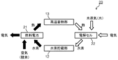
まず、本発明に係る水素電力貯蔵システムの第1の実施形態について説明する。図1は本発明の第1の実施形態による水素電力貯蔵システムの構成を模式的に示すブロック図である。図1に示す水素電力貯蔵システム(装置)10は、電力/水素変換装置11を具備している。電力/水素変換装置11は、発電と水蒸気の電解(水素の生成)とを、時間的に切り替えて行なうことが可能な装置であり、具体的には固体酸化物電解質を備える固体電解質燃料電池からなるものである。
First, a first embodiment of a hydrogen power storage system according to the present invention will be described. FIG. 1 is a block diagram schematically showing the configuration of the hydrogen power storage system according to the first embodiment of the present invention. A hydrogen power storage system (device) 10 shown in FIG. 1 includes a power /
固体電解質燃料電池は、水素と酸化剤ガスとを用いて発電する発電部と、水蒸気を電気分解する電解部とを兼ねるものである。図1において、発電運転モードにおける電気(電力)、空気(酸素)、水素、熱の流れの向きを黒矢印で示し、電解運転モードにおける電気(電力)、水蒸気、熱、水素の流れの向きを白矢印で示す。 The solid electrolyte fuel cell serves as both a power generation unit that generates power using hydrogen and an oxidant gas and an electrolysis unit that electrolyzes water vapor. In FIG. 1, the direction of the flow of electricity (electric power), air (oxygen), hydrogen, and heat in the power generation operation mode is indicated by black arrows, and the direction of the flow of electricity (electric power), water vapor, heat, and hydrogen in the electrolysis operation mode is indicated. Shown with white arrows.
発電運転モードにおいては、電力/水素変換装置(固体電解質燃料電池)11の水素極(燃料極)に水素が供給されると共に、酸化剤極に酸化剤ガス(酸素または酸素を含む空気)が供給されて発電が行われる。一方、電解(水素生成)運転モードでは、電力/水素変換装置(固体電解質燃料電池)11の水素極側に水蒸気が供給され、それと同時に電力が供給され、水蒸気を電気分解して水素が生成される。 In the power generation operation mode, hydrogen is supplied to the hydrogen electrode (fuel electrode) of the power / hydrogen conversion device (solid electrolyte fuel cell) 11 and oxidant gas (oxygen or air containing oxygen) is supplied to the oxidant electrode. Then, power generation is performed. On the other hand, in the electrolysis (hydrogen generation) operation mode, water vapor is supplied to the hydrogen electrode side of the power / hydrogen conversion device (solid electrolyte fuel cell) 11, and at the same time, electric power is supplied, and hydrogen is electrolyzed to generate hydrogen. The
水素電力貯蔵システム10は、電解(水素生成)運転モードのときに発生した水素を貯蔵する水素貯蔵部12を具備している。水素貯蔵部12としては、例えば水素貯蔵タンクが用いられる。水素貯蔵部12に貯蔵された水素は、発電運転モードのときに電力/水素変換装置(固体電解質燃料電池)11の水素極(燃料極)に供給される。
The hydrogen
さらに、水素電力貯蔵システム10は発電運転モードのときに電力/水素変換装置11で発生する650〜1000℃の高温の熱を貯蔵する高温蓄熱部13を具備している。高温蓄熱部13に貯蔵された高温の熱は、電解運転モードのときに電力/水素変換装置11に供給される。水蒸気電解は吸熱反応であるため、外部から熱の供給が必要である。なお、ここでは図示を省略したが、水素電力貯蔵システム10は高温蓄熱部13に加えて低温蓄熱部を具備している。高温蓄熱部および低温蓄熱部の詳細については後述する。
Furthermore, the hydrogen
水素電力貯蔵システム10においては、例えば一般的に電力需要の少ない夜間に電力を使う水蒸気の電解運転を行なって水素を水素貯蔵部12に貯蔵し、電力需要の多い日中は水素貯蔵部12に貯蔵されていた水素を用いて発電運転を行なう。発電運転時に発生した熱は、排出される水蒸気またはこれと熱交換させた熱媒体を通して、高温蓄熱部13に蓄熱される。高温蓄熱部13では、例えば650〜1000℃の熱が蓄熱される。
In the hydrogen
電解運転時には、電力/水素変換装置(固体電解質燃料電池)11の水素極側に水(水蒸気)を供給する。このとき、電解運転時に必要な熱を、水蒸気または熱媒体を通して高温蓄熱部13から放熱させる。放熱する水蒸気または熱媒体の温度は、例えば600〜1000℃とする。水素極側では水蒸気の電解により水素が生成して排出されるため、これを水素貯蔵部12に蓄える。同時に、酸素極側では酸素が生成して排出される。
During the electrolysis operation, water (steam) is supplied to the hydrogen electrode side of the power / hydrogen conversion device (solid electrolyte fuel cell) 11. At this time, heat necessary for the electrolytic operation is radiated from the high-temperature
高温蓄熱部13の具体的な構成例について、図2を参照して説明する。図2は第1の実施形態の水素電力貯蔵システム10の高温蓄熱部13を構成する蓄熱装置の一例を示す斜視図である。高温蓄熱部(蓄熱装置)13は、蓄熱材が封入される複数のカプセル14と、これらカプセル14を収容する蓄熱器容器15とを具備する。蓄熱器容器15はカプセル14の周りを流れる熱媒流体の流路を形成するものである。
A specific configuration example of the high-temperature
カプセル14は例えば円筒形の容器であり、その内部には蓄熱材(図示せず)が封入されている。高温蓄熱部13に用いられる蓄熱材は、蓄熱するときに溶融すると共に放熱するときに凝固する融点を有するものであり、例えば650〜1000℃の温度域に融点を持ち、融解熱が200kJ/kg以上で、固体および液体の比熱が1kJ/kg・K以上であることが好ましい。カプセル14は封入する蓄熱材に対して耐食性を有し、650〜1000℃の熱伝導率が10W/m・K以上であることが好ましい。
The
発電運転時には、電力/水素変換装置11で発生した熱により得られる、例えば650〜1000℃の高温の水蒸気またはこれと熱交換させた熱媒流体が、蓄熱器容器15内に導入されてカプセル14の外側を流れる。これによって、カプセル14およびその内部に封入された固体状の蓄熱材が加熱される。蓄熱材は加熱されて溶融し、固体から液体に変化する。この固体から液体への相転移時の潜熱を利用することによって、比較的少量の蓄熱材で大きな熱量を蓄えることができる。
During the power generation operation, high-temperature steam of, for example, 650 to 1000 ° C. obtained by heat generated in the power /
電解運転時には、液体状の蓄熱材が凝固する際に生じる高温の熱を、カプセル14を通じて熱媒流体に伝える。この高温の熱媒流体を電力/水素変換装置11に送ることによって、電解運転時に必要な熱を供給することができる。この場合、水蒸気等の熱媒流体は蓄熱材である溶融塩等と直接接触せず、カプセル14の外側の流路を通過する。
During the electrolysis operation, high-temperature heat generated when the liquid heat storage material solidifies is transmitted to the heat transfer fluid through the
高温蓄熱部13に用いる蓄熱材としては、塩化ナトリウム(NaCl)、塩化カリウム(KCl)、塩化マグネシウム(MgCl2)、塩化カルシウム(CaCl2)、フッ化リチウム(LiF)、フッ化ナトリウム(NaF)、炭酸リチウム(Li2CO3)、炭酸ナトリウム(Na2CO3)、炭酸カリウム(K2CO3)、および水素化リチウム(LiH)から選ばれる少なくとも1種が例示される。これらは混合物として使用してもよい。
Examples of the heat storage material used for the high-temperature
電力/水素変換装置(固体電解質燃料電池)11の固体電解質の種類や運転条件によって、発電時に排出される熱の温度が異なるため、排出される熱の温度と蓄熱容量とに応じて蓄熱材の種類を選定することが好ましい。上述した化合物(溶融塩)を単体として用いることによって、変動する温度や装置の大型化で問題となる蓄放熱特性の変動を抑えることができ、これにより水素電力貯蔵システム10の安定化を図ることが可能となる。
Since the temperature of heat discharged during power generation differs depending on the type of solid electrolyte and the operating conditions of the power / hydrogen conversion device (solid electrolyte fuel cell) 11, the temperature of the heat storage material depends on the temperature of the discharged heat and the heat storage capacity. It is preferable to select the type. By using the above-mentioned compound (molten salt) as a simple substance, fluctuations in the heat storage and heat dissipation characteristics, which are problematic due to fluctuating temperatures and device size, can be suppressed, thereby stabilizing the hydrogen
カプセル14は、炭化ケイ素(SiC)焼結体、炭化ケイ素−シリコン(SiC−Si)複合焼結体、炭化ケイ素基長繊維(SiC−長繊維(SiC長繊維等))複合材料、炭化ホウ素(B4C)焼結体、窒化ケイ素(Si3N4)焼結体、窒化ホウ素(BN)焼結体、および黒鉛(C)から選ばれる少なくとも1種のセラミックス部材で構成することが好ましい。セラミックス部材で構成されたカプセル14によれば、蓄熱材と水蒸気または熱媒流体との熱伝達を向上させることができ、蓄熱装置の軽量化や小型化と共に、総合効率の向上を実現することができる。
The
カプセル14は、少なくとも一方が容器形状を有する第1および第2のセラミックス部材により構成される。セラミックス部材の具体例は上記した通りである。図3にカプセル14の第1の構成例を示す。図3に示すカプセル14は、容器状の第1のセラミックス部材16と蓋状の第2のセラミックス部材17とを有している。なお、第1のセラミックス部材16と第2のセラミックス部材17の双方が容器形状を有していてもよい。このようなカプセル14に蓄熱材を封入する方法としては、以下に示す方法が挙げられる。
The
まず、図3(a)に示すように、蓄熱材(図示せず)が収容された第1のセラミックス部材16の開口部上に、接合材18を介して第2のセラミックス部材17を配置する。接合材18としては、セラミック前駆体、カーボン接着剤、シリコンろう材等が用いられる。第1のセラミックス部材16と第2のセラミックス部材17とは、炭化ケイ素−シリコン複合体等を適用して接合することも可能である。次いで、図3(b)に示すように、接合材18に応じた温度で熱処理することによって、第1のセラミックス部材16と第2のセラミックス部材17とを接合層19を介して接合する。
First, as shown in FIG. 3A, the second
セラミック前駆体としては、ポリカルボシラン、ポリカルボシラザン、ポリシラザン、ポリボロシロキサン、ポリメタロキサン等が用いられる。これらは焼成後に接合層19としてSi−C系セラミックス、Si−C−N系セラミックス、Si−O系セラミックス、Si−B−C系セラミックス等からなるセラミックス層を生成する。カーボン接着剤は黒鉛粉末と樹脂等を含み、焼成後には接合層19としてカーボン層が生成される。シリコンろう材としては箔やペースト等が用いられ、これらは焼成後(ろう付後)に接合層19としてシリコン層を生成する。
As the ceramic precursor, polycarbosilane, polycarbosilazane, polysilazane, polyborosiloxane, polymetalloxane, or the like is used. These form a ceramic layer made of Si—C ceramics, Si—C—N ceramics, Si—O ceramics, Si—B—C ceramics or the like as the
炭化ケイ素−シリコン複合体を適用した接合方法は、カーボン接着剤や有機樹脂系接着剤等の炭素成分を含む接着剤を接合材18として用いて、第1のセラミックス部材16と第2のセラミックス部材17とを接着した後、シリコン(Si)の存在下で熱処理することによって、炭化ケイ素−シリコン複合体からなる接合層19を形成して第1のセラミックス部材16と第2のセラミックス部材17とを接合する方法である。シリコンは、例えば接着層(接合材18)に溶融シリコンを含浸することにより供給される。この際、溶融シリコンの一部を積極的に残存させることによって、炭化ケイ素−シリコン複合体からなる接合層19を形成することができる。
The bonding method using the silicon carbide-silicon composite includes the first
第1のセラミックス部材16と第2のセラミックス部材17とを接合して構成したカプセル14内には、蓄熱材が封入される。カプセル14内に蓄熱材を封入する場合、緻密で強度を有する接合ができなければ、接合部から蓄熱材が漏れてしまう等の問題が発生する。また、伝熱管を兼ねるセラミックス部材16、17と接合部との熱物性に差異が生じていると、蓄放熱時の熱サイクルにより接合部を起点とする破損等が発生しやすい。上述した接合層19はいずれも緻密で高強度であり、また熱物性にも優れるため、接合部からの蓄熱材の漏れや接合部を起点とする破損等を抑制することができる。従って、安定した蓄放熱特性を有する蓄熱装置を得ることが可能となる。
A heat storage material is enclosed in the
第1のセラミックス部材16と第2のセラミックス部材17との接合層19には、炭化ケイ素−シリコン複合体を適用することが好ましい。接合層19を構成する炭化ケイ素−シリコン複合体は、炭化ケイ素粒子と、炭化ケイ素粒子の隙間に網目状に連続して存在するシリコン相とを有する組織を備えることが好ましい。このような炭化ケイ素−シリコン複合体は、第1の炭化ケイ素粒子と炭素とを有する多孔質体に溶融シリコンを含浸し、多孔質体中の炭素を溶融シリコンと反応させて第2の炭化ケイ素粒子を生成すると共に、溶融シリコンの一部をシリコン相として残存させることにより形成することができる。
A silicon carbide-silicon composite is preferably applied to the
第1の炭化ケイ素粒子と炭素とを有する多孔質体は、例えば以下のようにして形成される。まず、接合材18として、第1の炭化ケイ素粒子となる炭化ケイ素粉末と炭素粉末と室温硬化型樹脂およびその硬化剤とを含有する粘性材料(接合用材料)を用意する。炭化ケイ素粉末は0.5〜5μmの範囲の平均粒子径を有することが好ましい。炭素粉末は0.3〜3μmの範囲の平均粒子径を有することが好ましい。さらに、粘性材料中の全粉末成分に対する炭化ケイ素粉末の体積比は18〜60%の範囲とすることが好ましく、炭化ケイ素粉末と炭素粉末との合計質量比は粘性材料全体の29〜55%の範囲とすることが好ましい。これら各数値の限定理由については後述する。
The porous body having the first silicon carbide particles and carbon is formed as follows, for example. First, as the
次いで、蓄熱材(図示せず)が収容された第1のセラミックス部材16の開口部上に、上記した粘性材料からなる接合材18を介して第2のセラミックス部材17を配置する。溶融シリコンの供給源としてはシリコン箔等を用いることができる。粘性材料を第2のセラミックス部材17の接合面に塗布する場合、シリコン箔は粘性材料と接触するように第1のセラミックス部材16の接合面に配置される。あるいは、第1のセラミックス部材16と第2のセラミックス部材17との間に粘性材料を配置した場合、シリコン箔はその周囲に巻き付けるようにして配置してもよい。粘性材料とシリコン箔とが接していれば、熱処理時において多孔質体内に溶融シリコンを十分に供給することができる。
Next, the second
次に、粘性材料中の室温硬化型樹脂を室温下で硬化させて固化体とする。これによって、第1のセラミックス部材16と第2のセラミックス部材17とは予備的に接着されるため、熱処理炉への搬送時や取扱い時における蓄熱材のこぼれ等を防止することができる。続いて、粘性材料の固化体に熱処理を施すことによって、室温硬化型樹脂の硬化物を炭化する。これによって、粘性材料の固化体は多孔質化される。そして、このような多孔質体に溶融シリコンを含浸し、多孔質体中の炭素を溶融シリコンと反応させて第2の炭化ケイ素粒子を生成すると共に、溶融シリコンの一部をシリコン相として残存させることによって、炭化ケイ素−シリコン複合体からなる接合層19が形成される。なお、炭化ケイ素−シリコン複合体からなる接合層19の形成条件の詳細については後述する。
Next, the room temperature curable resin in the viscous material is cured at room temperature to obtain a solidified body. Thereby, since the first
カプセル14を構成する第1および第2のセラミックス部材16、17の形状は、図3に示す形状に限られるものではない。容器状の第1のセラミックス部材16と蓋状の第2のセラミックス部材17との接合面の形状は、図4および図5に示すように噛み合せ形状とすることも有効である。図4および図5は第2のセラミックス部材17の接合面に突起を設けると共に、第1のセラミックス部材16の接合面に突起に対応する凹みを設けた接合面を示している。このような接合面の形状によれば、カプセル14の内部に封入する蓄熱材の漏れ等をより確実に抑制することができる。
The shape of the first and second
天候の変動が大きい地域での太陽エネルギーや風力等の再生エネルギーについては、発電と水蒸気電解とを行なう固体電解質燃料電池を備える水素電力貯蔵システムを採用することが電力貯蔵効率の向上に有効である。夜間電力や天候の変動の少ない地域での太陽エネルギー等の再生エネルギーにおいても、発電と水蒸気電解とを行なう固体電解質燃料電池を備える水素電力貯蔵システムを採用することが電力貯蔵効率の向上に有効である。この実施形態の水素電力貯蔵システム10は、発電時に排出される650〜1000℃の熱を蓄熱し、その熱を水蒸気の電解時に使用するため、蓄熱された熱を有効に活用することができる。従って、水素電力貯蔵システムの総合効率を大幅に高めることが可能となる。
For renewable energy such as solar energy and wind power in areas with large weather fluctuations, it is effective to improve power storage efficiency by adopting a hydrogen power storage system equipped with a solid electrolyte fuel cell that performs power generation and steam electrolysis. . For renewable energy such as solar energy in areas with little nighttime power and weather fluctuations, it is effective to improve the power storage efficiency by adopting a hydrogen power storage system equipped with a solid electrolyte fuel cell that performs power generation and steam electrolysis. is there. The hydrogen
次に、本発明に係る水素電力貯蔵システムの第2の実施形態について説明する。図6は本発明の第2の実施形態による水素電力貯蔵システムの構成を模式的に示すブロック図である。図6に示す水素電力貯蔵システム20は、水素と酸化剤ガスとを用いて発電する発電部21と、水蒸気を電気分解する電解部22とを具備している。発電部21には、例えば固体酸化物電解質を備える固体電解質燃料電池が適用される。電解部22には、固体酸化物電解質を備える水蒸気電解セルが適用される。電解部22を構成する水蒸気電解セルは、発電部21を構成する固体電解質燃料電池とは別個の装置である。
Next, a second embodiment of the hydrogen power storage system according to the present invention will be described. FIG. 6 is a block diagram schematically showing the configuration of the hydrogen power storage system according to the second embodiment of the present invention. A hydrogen
第2の実施形態においては、第1の実施形態における電力/水素変換装置11に相当する部分が、発電を行なう燃料電池(発電部21)と水蒸気を電気分解する水蒸気電解セル(電解部22)とに分離されており、それぞれ別個の装置で構成されている。その他の構成は第1の実施形態と同様である。第2の実施形態においては、第1の実施形態のような発電と水蒸気電解との間の運転モードの切り替えが不要であり、より柔軟に発電と水蒸気電解とを行なうことができる。そのため、電力需要の変動等に対してより柔軟に対応でき、電力の安定供給に寄与するものである。さらに、第1の実施形態と同様に、熱を有効利用した水素電力貯蔵システムの総合効率を向上させることができる。
In the second embodiment, a portion corresponding to the power /
次に、本発明に係る水素電力貯蔵システムの第3の実施形態について説明する。図7は本発明の第3の実施形態による水素電力貯蔵システムの構成を模式的に示すブロック図である。第3の実施形態は高温蓄熱部13と低温蓄熱部31とを備える水素電力貯蔵システム30を示すものである。第3の実施形態の水素電力貯蔵システム30は、第1の実施形態の高温蓄熱部13に加えて低温蓄熱部31を備えている。
Next, a third embodiment of the hydrogen power storage system according to the present invention will be described. FIG. 7 is a block diagram schematically showing the configuration of the hydrogen power storage system according to the third embodiment of the present invention. The third embodiment shows a hydrogen
第3の実施形態の水素電力貯蔵システム30において、発電時に電力/水素変換装置11で発生した熱は、水蒸気またはこれと熱交換させた熱媒体を通して高温蓄熱部13に蓄熱される。高温蓄熱部13では650〜1000℃の熱が蓄熱される。さらに、高温蓄熱部13で熱交換された後の100〜600℃の熱は、水蒸気またはこれと熱交換させた熱媒体を通して低温蓄熱装置30に蓄熱される。
In the hydrogen
水蒸気の電解時においては、低温蓄熱部31から放熱された熱で水を蒸発させて水蒸気を生成し、この水蒸気を電力/水素変換装置11の水素極側に供給する。さらに、水蒸気の電解時に必要な熱は、水蒸気または熱媒体を通して高温蓄熱部13から放熱させて供給する。放熱する水蒸気または熱媒体の温度は、例えば600〜900℃とする。電力/水素変換装置11の水素極側では水蒸気の電解により水素が生成して排出されるため、これを水素貯蔵部12に蓄える。同時に、酸素極側では酸素が生成して排出される。
During electrolysis of water vapor, water is evaporated by the heat radiated from the low-temperature
低温蓄熱部31には、図2に示した高温蓄熱部13と同様な構造を有する蓄熱装置が適用される。低温蓄熱部31に用いられる蓄熱材は、100〜200℃の温度域に融点を持ち、融解熱が150kJ/kg以上で、固体および液体の比熱が1kJ/kg・K以上の有機物や溶融塩を用いることが好ましい。そのような蓄熱材を構成する有機物としては、キシリトール、エリスリトール、マンニトール、ソルビトール、アルジトール、尿素等が挙げられる。溶融塩としては、塩化アルミニウム(AlCl3)、塩化鉄(FeCl3)、水酸化リチウム(LiOH)、水酸化ナトリウム(NaOH)、水酸化カリウム(KOH)、亜硝酸ナトリウム(NaNO2)、硝酸リチウム(LiNO3)、硝酸ナトリウム(NaNO3)、硝酸カリウム(KNO3)等が挙げられる。
A heat storage device having a structure similar to that of the high temperature
次に、本発明に係る水素電力貯蔵システムの第4の実施形態について説明する。図8は本発明の第4の実施形態による水素電力貯蔵システムの構成を模式的に示すブロック図である。第4の実施形態の水素電力貯蔵システム40は、第2の実施形態と同様に、発電部(固体酸化物電解質を備える固体電解質燃料電池)21と、それとは別個の電解部(固体酸化物電解質を備える水蒸気電解セル)22とを具備している。それ以外の構成については第3の実施形態と同様とされている。
Next, a fourth embodiment of the hydrogen power storage system according to the present invention will be described. FIG. 8 is a block diagram schematically showing the configuration of the hydrogen power storage system according to the fourth embodiment of the present invention. As in the second embodiment, the hydrogen
第4の実施形態の水素電力貯蔵システム40は、第2の実施形態と第3の実施形態の特徴を併せ持つものである。第4の実施形態では第3の実施形態のような発電と電解との間の運転モードの切り替えが不要であり、より柔軟に発電と電解を行なうことができる。そのため、電力需要の変動等に対してより柔軟に対応でき、電力の安定供給に寄与するものである。また、第3の実施形態と同様に、高温蓄熱部13に加えて低温蓄熱部31を具備するため、熱を有効利用した水素電力貯蔵システムの総合効率がより向上する。
The hydrogen
上述した各実施形態は本発明の水素電力貯蔵システムの例示であり、本発明はこれらに限定されるものではない。例えば、第3および第4の実施形態における低温蓄熱部31の構造は、図2に示す高温蓄熱部13と同様のものでなくてもよい。低温蓄熱部31には前述した特許文献3ないし特許文献6のいずれかに記載された潜熱蓄熱装置の構造を適用することができる等、本発明の技術的思想の範囲内で拡張もしくは変更することができ、この拡張、変更した実施形態も本発明の技術的範囲に含まれるものである。
Each embodiment mentioned above is an illustration of the hydrogen power storage system of the present invention, and the present invention is not limited to these. For example, the structure of the low-temperature
次に、本発明のセラミックス接合用材料とそれを用いたセラミックス複合部材の製造方法の実施形態について説明する。この実施形態によるセラミックス複合部材の製造方法(セラミックス部材の接合方法)は、前述した水素電力貯蔵システムの実施形態におけるカプセル14の形成方法(第1のセラミックス部材16と第2のセラミックス部材17との接合方法)に適用されるものであり、その際の具体的な条件等を示すものである。ただし、この実施形態のセラミックス接合用材料とセラミックス複合部材の製造方法はそれだけに限られるものではなく、各種セラミックス体の接合や補修に適用可能である。
Next, an embodiment of a method for manufacturing a ceramic bonding material and a ceramic composite member using the same according to the present invention will be described. A method for manufacturing a ceramic composite member (a method for joining ceramic members) according to this embodiment is a method for forming a capsule 14 (the first
この実施形態のセラミックス接合用材料は、炭化ケイ素粉末と炭素粉末と室温硬化型樹脂とを含有する混合物からなる第1の成分と、第1の成分(混合物)を硬化させる硬化剤(室温硬化型樹脂を硬化させる硬化剤)からなる第2の成分とを具備している。セラミックス接合用材料は、第1の成分と第2の成分とを混合して調製された粘性材料として、セラミックス体の接合や補修に用いられるものである。すなわち、セラミックス接合用材料は、第1の成分と第2の成分との混合物(粘性材料)として、複数のセラミックス体を接合したセラミックス接合部材やセラミックス体の一部を補修したセラミックス補修部材等のセラミックス複合部材の製造に使用される。 The ceramic bonding material of this embodiment includes a first component made of a mixture containing silicon carbide powder, carbon powder, and a room temperature curable resin, and a curing agent (room temperature curable type) that cures the first component (mixture). And a second component made of a curing agent that cures the resin. The ceramic bonding material is a viscous material prepared by mixing the first component and the second component, and is used for bonding or repairing ceramic bodies. That is, the ceramic bonding material is a mixture of a first component and a second component (viscous material), such as a ceramic bonding member in which a plurality of ceramic bodies are bonded or a ceramic repair member in which a part of the ceramic body is repaired. Used in the manufacture of ceramic composite members.
セラミックス接合用材料を接合や補修に適用するセラミックス体としては、炭化ケイ素、窒化ケイ素、それらを主として含む複合化合物等のケイ化物セラミックスの成形体や焼結体が挙げられる。また、ケイ化物セラミックス以外にも適用可能であり、炭化ホウ素や黒鉛等の炭化物セラミックスに対しても有効である。セラミックス体の具体例としては、炭化ケイ素−炭素複合成形体、炭化ケイ素−シリコン複合焼結体、炭化ケイ素焼結体、窒化ケイ素焼結体、黒鉛が挙げられる。特に、炭化ケイ素系のセラミックス体に対してセラミックス接合用材料は特に有効である。 Examples of the ceramic body to which the ceramic bonding material is applied for bonding and repair include a molded body and a sintered body of silicide ceramics such as silicon carbide, silicon nitride, and a composite compound mainly containing them. Further, it can be applied to other than silicide ceramics, and is effective for carbide ceramics such as boron carbide and graphite. Specific examples of the ceramic body include a silicon carbide-carbon composite molded body, a silicon carbide-silicon composite sintered body, a silicon carbide sintered body, a silicon nitride sintered body, and graphite. In particular, ceramic bonding materials are particularly effective for silicon carbide ceramic bodies.
この実施形態のセラミックス接合用材料は、後に詳述する成形工程、熱処理工程、溶融シリコンの含浸工程等を経て炭化ケイ素(SiC)−シリコン(Si)複合体を形成するものである。SiC−Si複合体は、接合用材料中の炭化ケイ素粉末に基づく第1のSiC粒子と、接合用材料中の炭素成分(炭素粉末や室温硬化型樹脂の硬化物に熱処理(炭化処理)を施して生成された多孔質炭素)と溶融シリコンとの反応により生成された第2のSiC粒子と、第1および第2のSiC粒子の隙間を埋めるSi相(遊離Si相)とを備える。このようなSiC−Si複合体は、複数のケイ素系セラミックス体間を接合する接合部やケイ素系セラミックス体の一部を補修する補修部を構成するものである。 The ceramic bonding material of this embodiment forms a silicon carbide (SiC) -silicon (Si) composite through a molding process, a heat treatment process, a molten silicon impregnation process, and the like described in detail later. The SiC-Si composite is obtained by subjecting the first SiC particles based on the silicon carbide powder in the bonding material and the carbon component in the bonding material (carbon powder or a cured product of room temperature curable resin to heat treatment (carbonization treatment)). Porous carbon generated in this manner and molten silicon, and a Si phase (free Si phase) that fills the gap between the first and second SiC particles. Such a SiC-Si composite constitutes a joint part for joining a plurality of silicon-based ceramic bodies and a repair part for repairing a part of the silicon-based ceramic body.
セラミックス接合用材料の第1の成分は、接着性や粘性を付与する成分として室温硬化型樹脂を含有する混合物からなり、また第2成分は第1の成分(混合物)を硬化させる硬化剤からなる。室温硬化型樹脂および硬化剤は室温硬化型樹脂組成物を構成するものであり、室温硬化性を有するエポキシ系樹脂組成物やフェノール系樹脂組成物が使用される。室温硬化型樹脂組成物は室温硬化型樹脂を主成分とする主剤と硬化剤の2成分に分離されており、これらを作業直前に混合して使用する。セラミックス接合用材料では、例えば炭化ケイ素粉末と炭素粉末と室温硬化型樹脂組成物の主剤とを予め混合(第1の成分)しておき、これに硬化剤(第2の成分)を配合してセラミックス体の接合や補修に使用する。 The first component of the ceramic bonding material is composed of a mixture containing a room temperature curable resin as a component that imparts adhesiveness and viscosity, and the second component is composed of a curing agent that cures the first component (mixture). . The room temperature curable resin and the curing agent constitute the room temperature curable resin composition, and an epoxy resin composition or a phenol resin resin having room temperature curable properties is used. The room temperature curable resin composition is separated into two components, a main component mainly composed of a room temperature curable resin, and a curing agent, and these are mixed and used immediately before the work. In a ceramic bonding material, for example, silicon carbide powder, carbon powder, and a main component of a room temperature curable resin composition are mixed in advance (first component), and a curing agent (second component) is added thereto. Used for bonding and repairing ceramic bodies.
室温硬化型エポキシ系樹脂組成物において、主剤はエポキシ系樹脂組成物の主成分としてビスフェノールA型、ビスフェノールF型、クレゾールノボラック型、フェノールノボラック型、高分子型、エポキシポリオール等のエポキシ樹脂を含んでいる。主剤はエポキシ樹脂に加えて、一般的にシリカ、アルミナ、タルク、クレー、マイカ、石英粉末、酸化チタン、炭酸カルシウム等の無機充填剤を含んでいる。なお、第1の成分における炭化ケイ素粉末と炭素粉末も、樹脂組成物における無機充填剤の一部に相当する。さらに、主剤は硬化促進剤、着色剤、カップリング剤等のエポキシ系樹脂組成物に通常添加される各種の充填剤や添加剤、また希釈用の溶剤等を含んでいてもよい。従って、接合用材料の第1の成分は室温硬化型エポキシ樹脂に加えて、無機充填剤、硬化促進剤、着色剤、カップリング剤等の充填剤や添加剤、また希釈用の溶剤等を含むことができる。 In the room temperature curable epoxy resin composition, the main agent contains epoxy resin such as bisphenol A type, bisphenol F type, cresol novolak type, phenol novolak type, polymer type, epoxy polyol, etc. as the main component of the epoxy resin composition. Yes. The main agent generally contains an inorganic filler such as silica, alumina, talc, clay, mica, quartz powder, titanium oxide, calcium carbonate in addition to the epoxy resin. Note that the silicon carbide powder and the carbon powder in the first component also correspond to a part of the inorganic filler in the resin composition. Further, the main agent may contain various fillers and additives usually added to the epoxy resin composition such as a curing accelerator, a colorant, and a coupling agent, and a solvent for dilution. Accordingly, the first component of the bonding material includes, in addition to the room temperature curable epoxy resin, fillers and additives such as inorganic fillers, curing accelerators, colorants, coupling agents, and dilution solvents. be able to.
室温硬化型エポキシ系樹脂組成物中の硬化剤としては、例えば酸無水物、ポリアミン、ポリアミド、ノボラック樹脂、エピクロルヒドリン等が挙げられる。硬化剤の量(主剤中のエポキシ樹脂に対する量)はその種類や室温での硬化反応機構、さらに粘性材料の室温での硬化度合い等に応じて適宜に設定されるものである。このような室温硬化型エポキシ樹脂の硬化剤が接合用材料の第2の成分として用いられる。 Examples of the curing agent in the room temperature curable epoxy resin composition include acid anhydrides, polyamines, polyamides, novolac resins, epichlorohydrins, and the like. The amount of the curing agent (the amount with respect to the epoxy resin in the main agent) is appropriately set according to the type, the curing reaction mechanism at room temperature, the degree of curing of the viscous material at room temperature, and the like. Such a curing agent for room temperature curable epoxy resin is used as the second component of the bonding material.
室温硬化型フェノール系樹脂組成物において、主剤はフェノール系樹脂組成物の主成分としてノボラック、レゾール等のフェノール樹脂を含んでいる。主剤はフェノール樹脂に加えて、一般的にシリカ、アルミナ、タルク、クレー、マイカ、石英粉末、酸化チタン、炭酸カルシウム等の無機充填剤を含んでいる。さらに、主剤は硬化促進剤、着色剤、カップリング剤等のフェノール系樹脂組成物に通常添加される各種の充填剤や添加剤、また希釈用の溶剤等を含んでいてもよい。従って、接合用材料の第1の成分は室温硬化型フェノール樹脂に加えて、無機充填剤、硬化促進剤、着色剤、カップリング剤等の充填剤や添加剤、また希釈用の溶剤等を含むことができる。 In the room temperature curable phenolic resin composition, the main agent contains a phenolic resin such as novolak or resol as the main component of the phenolic resin composition. In addition to the phenol resin, the main agent generally contains inorganic fillers such as silica, alumina, talc, clay, mica, quartz powder, titanium oxide, and calcium carbonate. Furthermore, the main agent may contain various fillers and additives usually added to the phenolic resin composition such as a curing accelerator, a colorant, and a coupling agent, and a solvent for dilution. Accordingly, the first component of the bonding material includes, in addition to the room temperature curable phenolic resin, fillers and additives such as inorganic fillers, curing accelerators, colorants, coupling agents, and diluent solvents. be able to.
室温硬化型フェノール系樹脂組成物中の硬化剤としては、例えば酸無水物、ポリアミン、ポリアミド等が挙げられる。硬化剤の量はその種類や室温での硬化反応機構、さらに粘性材料の室温での硬化度合い等に応じて適宜に設定される。硬化剤の量(主剤中のフェノール樹脂に対する量)はその種類や室温での硬化反応機構、さらに粘性材料の室温での硬化度合い等に応じて適宜に設定されるものである。このような室温硬化型フェノール樹脂の硬化剤が接合用材料の第2の成分として用いられる。 Examples of the curing agent in the room temperature curable phenolic resin composition include acid anhydrides, polyamines, and polyamides. The amount of the curing agent is appropriately set according to the type, the curing reaction mechanism at room temperature, the degree of curing of the viscous material at room temperature, and the like. The amount of the curing agent (the amount with respect to the phenol resin in the main agent) is appropriately set according to the type, the curing reaction mechanism at room temperature, the degree of curing of the viscous material at room temperature, and the like. Such a curing agent for room temperature curable phenolic resin is used as the second component of the bonding material.
この実施形態のセラミックス接合用材料は、室温硬化型樹脂組成物の主剤に炭化ケイ素粉末と炭素粉末とを混合(第1の成分)し、この混合物に硬化剤(第2の成分)を混合して粘性材料(第1の成分と第2の成分との混合物)を調製して使用されるものである。セラミックス接合用材料は、室温硬化型樹脂からなる樹脂成分(液状樹脂成分等の流動性樹脂成分)と、炭化ケイ素粉末や炭素粉末による粉末成分とを有する。セラミックス接合用材料における粉末成分とは炭化ケイ素粉末および炭素粉末を示すものであり、室温硬化型樹脂に予め配合される粉末分は含まないものとする。 In the ceramic bonding material of this embodiment, silicon carbide powder and carbon powder are mixed (first component) with a main component of a room temperature curable resin composition, and a curing agent (second component) is mixed with this mixture. Thus, a viscous material (a mixture of the first component and the second component) is prepared and used. The ceramic bonding material has a resin component (a fluid resin component such as a liquid resin component) made of a room temperature curable resin, and a powder component made of silicon carbide powder or carbon powder. The powder component in the ceramic bonding material indicates silicon carbide powder and carbon powder, and does not include a powder component previously blended in the room temperature curable resin.
セラミックス接合用材料の第1の成分に配合する炭化ケイ素粉末は0.5〜5μmの範囲の平均粒子径を有している。炭化ケイ素粉末の平均粒子径が0.5μm未満であると、第1の成分と第2の成分との混合物(粘性材料)に熱処理を施して形成する多孔質体中の各構成成分(炭化ケイ素粉末、炭素粉末、樹脂に基づく炭素分)の分散状態、またそれに溶融Siを含浸して形成するSiC−Si複合体中の構成成分(第2のSiC粒子やSi相)の分布状態が不均一になる。一方、炭化ケイ素粉末の平均粒子径が5μmを超えるとSi相のサイズが大きくなりすぎる傾向がある。いずれの場合にもSiC−Si複合体の強度を十分に高めることができない。 The silicon carbide powder to be blended with the first component of the ceramic bonding material has an average particle diameter in the range of 0.5 to 5 μm. When the average particle diameter of the silicon carbide powder is less than 0.5 μm, each component (silicon carbide) in the porous body formed by subjecting the mixture (viscous material) of the first component and the second component to heat treatment Dispersion state of powder, carbon powder, carbon based on resin) and non-uniform distribution of constituent components (second SiC particles and Si phase) in SiC-Si composite formed by impregnating with molten Si become. On the other hand, when the average particle diameter of the silicon carbide powder exceeds 5 μm, the size of the Si phase tends to be too large. In either case, the strength of the SiC-Si composite cannot be sufficiently increased.
炭素粉末は0.3〜3μmの範囲の平均粒子径を有している。炭素粉末の平均粒子径が0.3μm未満であると凝集しやすく、SiC−Si複合体における第2のSiC粒子やSi相の分布状態が不均一になる。炭素粉末の平均粒子径が3μmを超えるとチョーキング現象が発生しやすくなり、SiC−Si複合体の強度が低下する。ここで、チョーキング現象とは、溶融シリコンとの反応によるSiCの生成時の体積増加で緻密なSiC層が表面側に形成され、内部への溶融シリコンの浸透が妨げられることで、内部の炭素がそのまま残ってしまう現象である。さらに、炭素粉末の平均粒子径が大きすぎるとSi相の平均径が大きくなる傾向があり、接合部や補修部を構成するSiC−Si複合体の強度の低下やバラツキを招くことになる。 The carbon powder has an average particle size in the range of 0.3 to 3 μm. When the average particle diameter of the carbon powder is less than 0.3 μm, the carbon powder is likely to aggregate, and the distribution state of the second SiC particles and the Si phase in the SiC-Si composite becomes uneven. When the average particle diameter of the carbon powder exceeds 3 μm, a choking phenomenon is likely to occur, and the strength of the SiC-Si composite is lowered. Here, the choking phenomenon is that a dense SiC layer is formed on the surface side due to an increase in volume when SiC is generated by reaction with molten silicon, and the penetration of molten silicon into the inside is prevented, so that the internal carbon is reduced. It is a phenomenon that remains as it is. Furthermore, if the average particle diameter of the carbon powder is too large, the average diameter of the Si phase tends to increase, leading to a decrease in strength and variations in the SiC-Si composite that constitutes the bonded portion and the repaired portion.
セラミックス接合用材料は炭化ケイ素粉末を全粉末成分に対して18〜60体積%の範囲で含んでいることが好ましい。炭化ケイ素粉末の体積比が18体積%未満であると、SiC−Si複合体中で骨材として機能する第1のSiC粒子が不足し、第2のSiC粒子やSi相の分布状態が不均一になりやすい。一方、炭化ケイ素粉末の体積比が60体積%を超えると、SiC−Si複合体中のSi相が多くなりすぎる。いずれの場合にもSiC−Si複合体の強度を十分に発現させることができないおそれがある。炭化ケイ素粉末の全粉末成分に対する体積比は22〜56%の範囲とすることが好ましい。 The ceramic bonding material preferably contains silicon carbide powder in a range of 18 to 60% by volume with respect to all powder components. When the volume ratio of the silicon carbide powder is less than 18% by volume, the first SiC particles functioning as an aggregate in the SiC-Si composite are insufficient, and the distribution state of the second SiC particles and the Si phase is not uniform. It is easy to become. On the other hand, when the volume ratio of the silicon carbide powder exceeds 60% by volume, the Si phase in the SiC-Si composite becomes too much. In either case, there is a possibility that the strength of the SiC-Si composite cannot be sufficiently expressed. The volume ratio of silicon carbide powder to all powder components is preferably in the range of 22 to 56%.
セラミックス接合用材料における炭化ケイ素粉末および炭素粉末の合計含有量は材料全体の29〜55質量%の範囲とすることが好ましい。このような粉末成分(炭化ケイ素粉末および炭素粉末)の含有量を適用することによって、複数のセラミックス体間を接合する接合部やセラミックス体の一部を補修する補修部を形成する際に、各種の形状、サイズの接合部や補修部を成形しやすい粘性材料(セラミックス接合材料の第1の成分と第2の成分との混合物)を得ることができる。すなわち、セラミックス接合用材料による接合部や補修部の成形性(施工性)を高めることができる。 The total content of silicon carbide powder and carbon powder in the ceramic bonding material is preferably in the range of 29 to 55 mass% of the entire material. When the content of such powder components (silicon carbide powder and carbon powder) is applied, various parts are formed when forming a joint part for joining a plurality of ceramic bodies and a repair part for repairing a part of the ceramic bodies. It is possible to obtain a viscous material (a mixture of the first component and the second component of the ceramic bonding material) that can easily form a bonded portion and a repaired portion of the above shape and size. That is, it is possible to improve the formability (constructability) of the joint portion and the repair portion using the ceramic joining material.
炭化ケイ素粉末および炭素粉末からなる粉末成分の合計含有量が55質量%を超えると、セラミックス接合用材料の第1の成分と第2の成分との混合物(粘性材料)の粘性が高くなりすぎる傾向がある。また、粉末成分の合計含有量が29質量%未満の場合には、逆に第1の成分と第2の成分との混合物(粘性材料)の粘性が低くなりすぎるおそれがある。いずれの場合にも、第1の成分と第2の成分との混合物(粘性材料)の施工性(成形性)が低下する。セラミックス接合用材料における炭化ケイ素粉末および炭素粉末の合計含有量は29〜40質量%の範囲とすることがより好ましい。 When the total content of the powder components composed of silicon carbide powder and carbon powder exceeds 55% by mass, the viscosity of the mixture (viscous material) of the first component and the second component of the ceramic bonding material tends to be too high. There is. On the other hand, when the total content of the powder components is less than 29% by mass, the viscosity of the mixture (viscous material) of the first component and the second component may be too low. In either case, the workability (formability) of the mixture (viscous material) of the first component and the second component is reduced. The total content of silicon carbide powder and carbon powder in the ceramic bonding material is more preferably 29 to 40% by mass.
さらに、接合または補修するセラミックス体が焼結体のように緻密質の場合には、粉末成分の含有量が比較的多いセラミックス接合用材料(粉末成分の含有量が55質量%側の接合用材料)を使用することが好ましい。逆に、セラミックス体が圧粉体等の成形体のように多孔質の場合には、粉末成分の含有量が比較的少ないセラミックス接合用材料(粉末成分の含有量が29質量%側の接合用材料)を使用することが好ましい。 Furthermore, when the ceramic body to be joined or repaired is dense like a sintered body, a ceramic joining material having a relatively high powder component content (a joining material having a powder component content of 55% by mass) ) Is preferably used. On the contrary, when the ceramic body is porous like a compact such as a green compact, a ceramic bonding material having a relatively small content of the powder component (for bonding with a powder component content of 29% by mass) Material) is preferably used.
セラミックス接合用材料中の粉末成分量が比較的多い(粉末成分の含有量が55質量%側)場合、第1の成分と第2の成分との混合物(粘性材料)の保形性が高くなり、セラミックス体に接合しやすくなる。ただし、セラミックス体が圧粉体のように多孔質の場合には、樹脂成分(液状成分)がセラミックス体に吸収されてしまうため、例えばセラミックス体同士を接合しにくくなる。このような場合には、粉末成分量が比較的少ないセラミックス接合用材料(粉末成分の含有量が29質量%側の接合用材料)を使用することが好ましい。このような接合用材料によれば、第1の成分と第2の成分との混合物(粘性材料)が圧粉体表面の凹部に食い込んで接着性が向上する。 When the amount of the powder component in the ceramic bonding material is relatively large (the content of the powder component is 55% by mass), the shape retention of the mixture (viscous material) of the first component and the second component is increased. It becomes easy to join the ceramic body. However, when the ceramic body is porous like a green compact, the resin component (liquid component) is absorbed by the ceramic body, so that it becomes difficult to join the ceramic bodies, for example. In such a case, it is preferable to use a ceramic bonding material having a relatively small amount of powder component (a bonding material having a powder component content of 29% by mass). According to such a bonding material, the mixture (viscous material) of the first component and the second component bites into the concave portion on the surface of the green compact, thereby improving the adhesiveness.
この実施形態のセラミックス接合用材料において、第1の成分と第2の成分とを混合して調製した粘性材料は、室温硬化型樹脂が有する流動性(液状性等)や粉末成分の配合量等に基づいて適度な粘性が付与されているため、セラミックス体の接合面や補修面に容易に成形することができる。さらに、第1の成分と第2の成分との混合物からなる粘性材料は室温で硬化するため、接合部や補修部に求められる所定の形状を容易に維持することができる。従って、この実施形態のセラミックス接合用材料を用いることによって、各種の形状やサイズのセラミックス体、特に大型構造部材や複雑形状部材を構成するセラミックス体に対して接合部や補修部を容易にかつ精度よく形成することが可能となる。 In the material for bonding ceramics of this embodiment, the viscous material prepared by mixing the first component and the second component is the fluidity (liquidity etc.) of the room temperature curable resin, the blending amount of the powder component, etc. Since moderate viscosity is imparted based on the above, it can be easily formed on the joint surface and repair surface of the ceramic body. Furthermore, since the viscous material which consists of a mixture of the 1st component and the 2nd component hardens | cures at room temperature, the predetermined shape calculated | required by a junction part and a repair part can be maintained easily. Therefore, by using the ceramic bonding material of this embodiment, it is possible to easily and accurately join and repair parts of various shapes and sizes of ceramic bodies, particularly ceramic bodies constituting large-sized structural members and complex-shaped members. It becomes possible to form well.
次に、本発明の実施形態によるセラミックス複合部材の製造方法について、図9を参照して説明する。図9は本発明の製造方法を適用したセラミックス接合部材の製造方法を示す断面図である。なお、本発明の製造方法を適用したセラミックス補修部材の製造方法は、セラミックス接合用材料の第1の成分と第2の成分との混合物(粘性材料)をセラミックス体の補修箇所に配置することを除いて、接合部材の製造方法と同様な工程を適用して実施される。ここでは接合部材の製造方法について主として説明する。 Next, the manufacturing method of the ceramic composite member by embodiment of this invention is demonstrated with reference to FIG. FIG. 9 is a cross-sectional view showing a method for manufacturing a ceramic bonding member to which the manufacturing method of the present invention is applied. In addition, the manufacturing method of the ceramic repair member to which the manufacturing method of this invention is applied arrange | positions the mixture (viscous material) of the 1st component of a ceramic joining material and a 2nd component at the repair location of a ceramic body. Except for this, the same steps as those for the manufacturing method of the joining member are applied. Here, the manufacturing method of a joining member is mainly demonstrated.
図9は本発明の実施形態によるセラミックス接合部材の製造工程を示している。まず、図9(a)に示すように、被接合部材(基材)となる第1および第2のセラミックス体51、52を用意する。ここでは2個のセラミックス体51、52を接合する工程について述べるが、被接合部材(基材)となるセラミックス体は3個もしくはそれ以上であってもよい。この実施形態をセラミックス補修部材の製造方法に適用する場合には、補修が必要なセラミックス体(基本的には1個のセラミックス体)を用意する。
FIG. 9 shows a process for manufacturing a ceramic joined member according to an embodiment of the present invention. First, as shown to Fig.9 (a), the 1st and 2nd
第1および第2のセラミックス体51、52は、前述したように炭化ケイ素、窒化ケイ素、それらを主として含む複合化合物等のケイ化物セラミックスの成形体や焼結体、また黒鉛等の炭化物セラミックスからなるものであることが好ましい。第1および第2のセラミックス体51、52は、炭化ケイ素−炭素複合成形体、炭化ケイ素−シリコン複合焼結体、炭化ケイ素焼結体、窒化ケイ素焼結体、および黒鉛から選ばれる少なくとも1種であることが好ましい。第1および第2のセラミックス体51、52は同種のセラミックス体または異種のセラミックス体のいずれであってもよい。第1および第2のセラミックス体51、52の一方が成形体で他方が焼結体であってもよい。
As described above, the first and second
この実施形態の接合工程は、特に炭化ケイ素−炭素複合成形体同士の接合、炭化ケイ素−シリコン複合焼結体同士の接合、炭化ケイ素焼結体同士の接合に好適であり、そのような場合により良い結果(接合強度や接合部を含むセラミックス接合部材(複合部材)の強度の向上効果等)を得ることができる。この実施形態をセラミックス補修部材の製造方法に適用する場合も同様であり、炭化ケイ素−シリコン複合焼結体や炭化ケイ素焼結体の補修に適用した場合により良い結果を得ることができる。 The bonding step of this embodiment is particularly suitable for bonding between silicon carbide-carbon composite molded bodies, bonding between silicon carbide-silicon composite sintered bodies, and bonding between silicon carbide sintered bodies. Good results (such as an effect of improving the bonding strength and the strength of the ceramic bonding member (composite member) including the bonding portion) can be obtained. The same applies to the case where this embodiment is applied to a method for manufacturing a ceramic repair member, and better results can be obtained when the embodiment is applied to repair of a silicon carbide-silicon composite sintered body or a silicon carbide sintered body.
セラミックス体51、52を構成する炭化ケイ素焼結体としては、通常の炭化ケイ素粉末の加圧焼結体や液相焼結体、あるいは炭素粉末を含む原料粉末(例えば炭素粉末と炭化ケイ素粉末との混合粉末)の反応焼結体等が挙げられる。セラミックス体51、52としての炭化ケイ素−炭素複合成形体は、炭化ケイ素粉末と炭素粉末との混合粉末の圧粉体であり、これに溶融シリコンを含浸することで炭化ケイ素−シリコン複合焼結体となる。
Examples of the silicon carbide sintered body constituting the
炭化ケイ素−炭素複合成形体は、例えば炭化ケイ素粉末と炭素粉末との混合粉末に粉体加圧成形や圧力鋳込み成形等の加圧成形を適用して作製される。混合粉末の加圧成形には金型プレス、ラバープレス、冷間等方圧プレス等が適用される。圧力鋳込み成形を適用する場合には、混合粉末を水または有機溶媒中に分散させてスラリーを作製し、このスラリーを適度な圧力下で鋳込み成形する。このような加圧成形を適用することによって、適度な密度(粉体の充填状態)を有する成形体が得られる。 The silicon carbide-carbon composite molded body is produced, for example, by applying pressure molding such as powder pressure molding or pressure casting to a mixed powder of silicon carbide powder and carbon powder. A die press, a rubber press, a cold isostatic press or the like is applied to the pressure forming of the mixed powder. When pressure casting is applied, a slurry is prepared by dispersing the mixed powder in water or an organic solvent, and this slurry is cast under an appropriate pressure. By applying such pressure molding, a molded body having an appropriate density (filled state of powder) can be obtained.
図9(a)に示すように、第1および第2のセラミックス体51、52の間に粘性材料53を配置する。粘性材料53は、炭化ケイ素粉末と炭素粉末と室温硬化型樹脂とを含有する混合物からなる第1の成分と、第1の成分(混合物)を硬化させる硬化剤からなる第2の成分とを混合して調製したものであり、炭化ケイ素粉末54、炭素粉末55および室温硬化型樹脂組成物(主剤と硬化剤とが混合されたもの)56とを有する。粘性材料53中の室温硬化型樹脂を室温下で硬化させて、所望の接合部材形状を有する形状物57を成形する。粘性材料53は形状物57の成形工程で硬化された室温硬化型樹脂の硬化物に基づいて第1および第2のセラミックス体51、52の接合面に接着された固化体となる。
As shown in FIG. 9A, a
このように、粘性材料53は室温下で固化させることができるため、第1のセラミックス体51と第2のセラミックス体52とを粘性材料53の固化体を介して接着した形状物57を、被接合部材を治具等で固定することなく、容易にかつ精度よく得ることが可能となる。さらに、その後の熱処理工程や溶融シリコンの含浸工程においても形状物57を治具等で固定する必要がないため、セラミックス体51、52や接合部材の形状、サイズ等による制約を緩和することができる。すなわち、各種の形状やサイズのセラミックス体51、52を粘性材料53の固化体により接着することが可能となる。
Thus, since the
さらに、粘性材料53は室温下で固化体とすることができるため、例えば第1およびセラミックス体51、52間の距離(接着距離)、ひいては粘性材料53の固化体に基づく接合部の厚さを精度よく制御することが可能となる。接着距離は接着層(粘性材料53の固化体層)の厚さに基づくものであり、さらに溶融シリコンの含浸後における接合層(SiC−Si複合体からなる層)の厚さに相当するものである。接合部(接合層)の厚さは第1のセラミックス体51と第2のセラミックス体52とを接合して構成した接合部材の強度特性等に影響を及ぼす。言い換えると、接合部の厚さを精度よく制御することによって、接合部材の強度やその再現性を高めることが可能となる。
Furthermore, since the
次に、図9(b)に示すように形状物57に熱処理を施して、室温硬化型樹脂の硬化物を炭化する。室温硬化型樹脂の硬化物は熱処理で分解されて炭素の多孔体58となり、この多孔体58中に炭化ケイ素粉末54や炭素粉末55が分散された状態となる。このような熱処理(炭化処理)に基づいて粘性材料53の固化体を多孔質体59とする。室温硬化型樹脂の硬化物を炭化するための熱処理は400〜1300℃の範囲の温度で実施することが好ましい。熱処理を減圧雰囲気で実施する場合は1Pa以下とすることが好ましい。このような条件下で熱処理工程を実施することで多孔質体59の形成性が向上する。
Next, as shown in FIG. 9B, the shaped
この後、多孔質体59に溶融シリコンを含浸することで、図9(c)に示すように第1および第2のセラミックス体51、52をSiC−Si複合体60からなる接合部を介して接合したセラミックス接合部材61を作製する。溶融シリコンの含浸工程は、多孔質体59を有する形状物57を減圧雰囲気中にて1400〜1500℃の範囲の温度に加熱し、この加熱状態の多孔質体59に溶融シリコンを減圧雰囲気下で含浸(真空含浸)することにより実施される。真空含浸時の減圧雰囲気は1Pa以下であることが好ましい。
Thereafter, the
セラミックス補修部材を作製する場合には、炭化ケイ素−シリコン複合焼結体や炭化ケイ素焼結体等からなるセラミックス体の補修箇所、例えば欠けやクラック等が生じた箇所に粘性材料(第1の成分と第2の成分との混合物)を塗布して成形する。補修箇所が深さを有する場合には、その部分に粘性材料を充填する。この後、粘性材料を塗布したセラミックス体に、上述した熱処理工程(炭化工程)および溶融シリコンの含浸工程を施すことによって、所望形状のセラミックス補修部材を作製する。 In the case of producing a ceramic repair member, a viscous material (first component) is applied to a repaired portion of a ceramic body made of a silicon carbide-silicon composite sintered body, a silicon carbide sintered body, or the like, for example, a place where a chip or a crack is generated. And a mixture of the second component) and molding. When the repaired portion has a depth, the portion is filled with a viscous material. Thereafter, the ceramic body coated with the viscous material is subjected to the heat treatment step (carbonization step) and the molten silicon impregnation step described above to produce a ceramic repair member having a desired shape.
多孔質化された粘性材料53の固化体(多孔質体59)内に存在する炭化ケイ素粉末54は、溶融シリコンの含浸工程においてもほとんど粒成長しないため、炭化ケイ素粉末54の平均粒子径とほぼ同等の粒径を有する第1のSiC粒子62となる。多孔質体59中の炭素成分、すなわち炭素粉末55や室温硬化型樹脂組成物56に由来する炭素58は、高温下で溶融シリコンと接触して反応し、炭化ケイ素(第2のSiC粒子63)を生成する。さらに、多孔質体59内には溶融シリコンが一部残存し、これが第1および第2のSiC粒子62、63の隙間にSi相64として存在することになる。
Since the
セラミックス体51、52が炭化ケイ素−炭素複合成形体等である場合には、多孔質体59と同時に2個の成形体にも溶融シリコンを含浸する。溶融シリコンの含浸工程において、2個の炭化ケイ素−炭素複合成形体は溶融シリコンと反応して炭化ケイ素−シリコン複合焼結体となる。すなわち、溶融シリコンの含浸工程で反応焼結させた2個の炭化ケイ素−シリコン複合焼結体を、これらと同時に反応させて形成したSiC−Si複合体60からなる接合部で一体化したセラミックス接合部材61を作製する。炭化ケイ素−シリコン複合焼結体は、接合部としてのSiC−Si複合体60と同様な組織を有する。
When the
SiC−Si複合体60からなる接合部は、第1および第2のSiC粒子62、63とそれらの隙間に網目状に連続して存在するSi相64とを備える。すなわち、SiC粒子62、63の隙間をSi相64で埋めた緻密な組織を有する。補修部をSiC−Si複合体で構成する場合にも同様な組織を有する。炭素成分と溶融シリコンとの反応に基づく第2のSiC粒子63は、粘性材料53中に配合された炭化ケイ素粉末54に基づく第1のSiC粒子62より小さい平均粒径を有する。炭化ケイ素粉末54や炭素粉末55の平均粒子径とそれに基づく第1および第2のSiC粒子62、63の平均粒径に基づいて、均質な複合組織(SiC粒子62、63の隙間に大きさが均質なSi相64を連続して存在させた組織)を有するSiC−Si複合体60が得られる。
A joint portion made of SiC-
さらに、SiC−Si複合体60は粘性材料53中の炭化ケイ素粉末54の全粉末成分に対する配合量(体積比で18〜60%)に基づいて適量のSiC粒子62、すなわち平均粒径が比較的大きい第1のSiC粒子62を有している。第1のSiC粒子62の含有量と炭化ケイ素粉末54の平均粒子径に基づくSiC粒子62の平均粒径等に基づいて、SiC−Si複合体60中の第2のSiC粒子63やSi相64の分布状態が均一化され、さらにSiC−Si複合体60の緻密性も向上する。これらによっても、SiC−Si複合体60の強度やその再現性を高めることが可能となる。
Furthermore, the SiC-
SiC−Si複合体60において、Si相64はSiC粒子62、63の隙間を埋めるだけでなく、SiC粒子62、63の隙間に網目状(ネットワーク状)に連続して存在していることが好ましい。Si相64の網目構造が分断されると、チョーキング現象(溶融シリコンの供給経路が断たれて炭素の反応が止まる現象)の発生を招き、残留炭素量が増大してSiC−Si複合体60からなる接合部の強度が低下するおそれがある。言い換えると、SiC粒子62、63の隙間にSi相64を連続して存在させることによって、緻密で高強度の接合部を得ることが可能となる。
In the SiC-
上述したセラミックス接合部材(複合部材)の製造工程において、多孔質体59は0.5〜5μmの範囲の平均気孔径を有することが好ましい。多孔質体59の平均気孔径は水銀圧入法を用いて円柱と仮定して求めた径の平均値を示すものとする。このような平均気孔径を有する多孔質体59に溶融シリコンを含浸することによって、SiC−Si複合体60中のSi相(遊離Si相)64の分布状態や平均径等に基づいて強度特性(SiC−Si複合体60の接合強度、SiC−Si複合体60自体の強度、SiC−Si複合体60を含む接合部材61の強度等)を向上させることが可能となる。
In the manufacturing process of the ceramic bonding member (composite member) described above, the
多孔質体59の平均気孔径が0.5μm未満であると、溶融シリコンの供給経路が断たれて残留炭素量の増大を招いたり、また炭素から炭化ケイ素を生成する際の体積膨張で割れが発生しやすくなる。多孔質体59の平均気孔径が5μmを超えるとSi相64の量が増大する。これらはいずれもSiC−Si複合体60の強度を低下させる。さらに、多孔質体59の平均気孔径が大きすぎると溶融シリコンを含浸する前に割れ等が生じやすくなり、セラミックス接合部材61の製造歩留りや強度が低下する。
If the average pore diameter of the
さらに、Si相54は0.2〜2μmの範囲の平均径を有することが好ましい。Si相64の平均径はSiC粒子62、63間の平均距離に相当する。Si相64の平均径は以下のようにして求めた値を示すものとする。まず、SiC−Si複合体60を有するセラミックス接合部材61を減圧下で1600℃に加熱し、SiC−Si複合体60中の遊離Siを除去する。Si相64の平均径は、遊離Siを除去して形成された細孔の径を、水銀圧入法を用いて円柱と仮定して求めた径の平均値を示すものとする。この値はSiC−Si複合体60の微構造を金属顕微鏡やSEMで断面観察した結果と一致する。
Furthermore, the
Si相64の平均径が小さいということは、強度が低いSi相64が微細化されていることを意味する。さらに、SiC粒子62、63の隙間にSi相64が均質に分布していることを意味する。SiC粒子62、63の隙間はSi相64で満遍なく充填されている。このように、Si相64の平均径を0.2〜2μmの範囲に制御することによって、SiC−Si複合体60からなる接合部の強度、さらに接合部を含むセラミックス接合部材61としての強度を再現性よく高めることが可能となる。
That the average diameter of the
Si相64の平均径が2μmを超える場合には、強度が低いSi相64が偏析されている状態に近くなり、SiC−Si複合体60の強度に対するSi相64の影響が大きくなる。従って、SiC−Si複合体60の強度やセラミックス接合部材61の強度が低下しやすくなる。Si相64の平均径が0.2μm未満になると、連続した網目状の構造を維持することが困難となる。これによって、SiC−Si複合体60に空孔や遊離炭素が生じやすくなり、接合部の強度にばらつきが生じやすくなる。補修部をSiC−Si複合体で構成する場合も同様である。
When the average diameter of the
Si相64の平均径は、溶融シリコンを含浸する前の多孔質体59の平均気孔径や粘性材料53に配合された炭化ケイ素粉末54や炭素粉末55の平均粒子径に基づいて制御することができる。すなわち、平均粒子径が0.5〜5μmの範囲の炭化ケイ素粉末54と平均粒子径が0.3〜3μmの範囲の炭素粉末55を用いると共に、多孔質体59の平均気孔径を0.5〜5μmの範囲に制御することによって、微細で均質なSi相64(例えば平均径が0.2〜2μmの範囲のSi相64)を得ることが可能となる。
The average diameter of the
セラミックス複合部材の製造工程において、溶融シリコンの含浸工程は1400〜1500℃の範囲の温度下で実施することが好ましい。溶融シリコンの含浸雰囲気は1Pa以下の減圧雰囲気とすることが好ましい。このような条件下で溶融シリコンの含浸工程を実施することによって、溶融シリコンの含浸性やSiC粒子63の形成性が向上すると共に、Si相64中の微細なポア(マイクロポアやナノポア)を大幅に減少させることができる。従って、SiC−Si複合体60の強度やその再現性を高めることが可能となる。
In the manufacturing process of the ceramic composite member, the impregnation step of molten silicon is preferably performed at a temperature in the range of 1400 to 1500 ° C. The impregnation atmosphere of molten silicon is preferably a reduced pressure atmosphere of 1 Pa or less. By performing the molten silicon impregnation step under such conditions, the impregnation of molten silicon and the formability of
この実施形態のセラミックス接合部材61の製造工程では、2個のセラミックス体51、52を粘性材料53で接着する際に、接合部を所定の形状に成形したままの状態で硬化させることができるため、大型構造部材や複雑形状部品等に適用可能であると共に、接合部の形状精度を高めることができる。従って、強度や熱的特性等の材料特性のばらつきを抑制した接合部を得ることが可能となる。
In the manufacturing process of the
上述した接合部によれば、それ自体の材料特性の向上に加えて、接合部を有するセラミックス接合部材61の材料特性やその再現性を向上させることが可能となる。また、被接合部材を治具等で固定する必要がないため、セラミックス接合部材61の製造コストや製造工数を低減することが可能となる。なお、接合部材の形状が複雑な場合や接合個所が多岐にわたるような場合において、治具等の使用を妨げるものではない。
According to the joint portion described above, it is possible to improve the material property and the reproducibility of the ceramic
さらに、セラミックス接合部材61の製造工程において、SiC−Si複合体60からなる接合部はセラミックス体51、52への接合強度に優れるだけでなく、それ自体の強度やその再現性に優れる。従って、複数のセラミックス体51、52を高強度に接合することができると共に、セラミックス接合部材61の強度を再現性よく高めることができる。これらによって、複雑形状や大型の構造部材や部品に好適な高強度のセラミックス接合部材61を低コストで提供することが可能となる。また、この実施形態の製造工程をセラミックス補修部材の製造に適用した場合も同様であり、セラミックス補修部材の高強度化、形状精度の向上、低コスト化等を図ることができる。
Furthermore, in the manufacturing process of the
上述したセラミックス接合部材61やセラミックス補修部材等の複合部材は、強度等の機械的特性を再現性よく高めることできるため、高強度が求められる各種部材や部品に適用することが可能となる。特に、大型構造物や複雑形状部品等の高強度化に大きく寄与する。セラミックス複合部材は、半導体製造装置用治具、半導体関連部品(ヒートシンクやダミーウエハ等)、ガスタービン用高温構造部材、蓄熱器用高温部材、宇宙および航空用構造部材、メカニカルシール部材、ブレーキ用部材、摺動部品、ミラー部品、ポンプ部品、熱交換器部品、化学プラント要素部品等、各種の装置部品や装置部材に適用することができる。特に、高強度が求められる装置部品や部材に好適に用いられる。
Since the composite member such as the
次に、本発明の具体的な実施例およびその評価結果について述べる。 Next, specific examples of the present invention and evaluation results thereof will be described.
(粘性材料1〜6)
以下のようにして粘性材料1〜6を作製した。まず、室温硬化型樹脂組成物として室温硬化性を有するエポキシ系樹脂組成物とフェノール系樹脂組成物とを用意した。表1に示す室温硬化型樹脂組成物の主剤に、平均粒子径が0.5〜5μmの範囲の炭化ケイ素粉末と平均粒子径が0.3〜3μmの範囲の炭素粉末とを添加して混合した。炭化ケイ素粉末および炭素粉末の平均粒子径、粘性材料における炭化ケイ素粉末の体積比および炭化ケイ素粉末と炭素粉末との合計質量比は表1に示す通りである。
(Viscous materials 1-6)
Viscous materials 1 to 6 were produced as follows. First, an epoxy resin composition having a room temperature curability and a phenol resin composition were prepared as room temperature curable resin compositions. To the main component of the room temperature curable resin composition shown in Table 1, silicon carbide powder having an average particle size in the range of 0.5 to 5 μm and carbon powder having an average particle size in the range of 0.3 to 3 μm are added and mixed. did. Table 1 shows the average particle diameter of the silicon carbide powder and the carbon powder, the volume ratio of the silicon carbide powder in the viscous material, and the total mass ratio of the silicon carbide powder and the carbon powder.
上述した室温硬化型樹脂組成物の主剤と炭化ケイ素粉末と炭素粉末との混合物に、室温硬化型樹脂組成物の硬化剤を添加し、十分に混合して粘性材料1〜6とした。なお、室温硬化型樹脂組成物の硬化剤は、後述する実施例1〜15のセラミックス複合部材の作製工程で粘性材料を施工する直前(接合部材ではセラミックス体の接合面間に配置する直前、補修部材ではセラミックス体の一部に配置する直前)に混合した。粘性材料1〜6の具体的な構成は表1に示す通りである。 Viscosity materials 1 to 6 were prepared by adding the curing agent of the room temperature curable resin composition to the mixture of the main component of the room temperature curable resin composition, the silicon carbide powder, and the carbon powder, and thoroughly mixing them. In addition, the curing agent of the room temperature curable resin composition is repaired immediately before the viscous material is applied in the manufacturing process of the ceramic composite member of Examples 1 to 15 described later (immediately before being placed between the bonding surfaces of the ceramic body in the bonding member) In the member, it was mixed immediately before being placed on a part of the ceramic body. Specific configurations of the viscous materials 1 to 6 are as shown in Table 1.
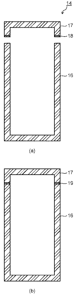
(実施例1)
平均粒子径が0.8μmの炭化ケイ素粉末と平均粒子径が0.4μmの炭素粉末(カーボンブラック)とを、質量比で10:3(=SiC:C)となるように混合した。この混合粉末を適当量の有機バインダと共に混合した後、溶媒中に分散させてスラリーを調製した。このスラリーを圧力鋳込み成形機を用いて成形型内に加圧しながら充填した。このようにして、2個のSiC−C複合成形体(圧粉体)を作製した。
Example 1
Silicon carbide powder having an average particle diameter of 0.8 μm and carbon powder (carbon black) having an average particle diameter of 0.4 μm were mixed so as to have a mass ratio of 10: 3 (= SiC: C). This mixed powder was mixed with an appropriate amount of an organic binder and then dispersed in a solvent to prepare a slurry. This slurry was filled into the mold while being pressurized using a pressure casting molding machine. In this way, two SiC-C composite molded bodies (green compacts) were produced.
次に、2個のSiC−C複合成形体の接合面間に表1の粘性材料1を配置した後、室温硬化型樹脂組成物を硬化させて所望の接合部材形状を有する形状物を成形した。この形状物を窒素またはアルゴン雰囲気中にて1000℃の温度に加熱して、室温硬化型樹脂組成物の硬化物を炭化した。この炭化処理で粘性材料の固化体は多孔質体となる。多孔質体の平均気孔径は1.0μmであった。この後、2個の成形体を多孔質体で繋げた形状物を、1Pa以下の減圧雰囲気中にて1450℃の温度に加熱しながら、2個の成形体および接合部を構成する多孔質体に溶融シリコンを含浸した。 Next, after arranging the viscous material 1 of Table 1 between the joining surfaces of two SiC-C composite molded bodies, the room temperature curable resin composition was cured to form a shape having a desired joining member shape. . This shaped product was heated to a temperature of 1000 ° C. in a nitrogen or argon atmosphere to carbonize the cured product of the room temperature curable resin composition. By this carbonization treatment, the solidified body of the viscous material becomes a porous body. The average pore diameter of the porous body was 1.0 μm. After that, the porous body constituting the two molded bodies and the joined portion is heated while heating the shape obtained by connecting the two molded bodies with the porous body to a temperature of 1450 ° C. in a reduced pressure atmosphere of 1 Pa or less. Was impregnated with molten silicon.
溶融シリコンの含浸工程において、2個の成形体を溶融シリコンと反応させてSiC−Si複合焼結体とすると共に、これらを多孔質体と溶融シリコンとの反応生成物であるSiC−Si複合体で接合した。このようにして得たセラミックス接合部材について、SiC−Si複合体からなる接合部の表面を研磨加工した後、微構造を電子顕微鏡で観察した。その結果、接合部はSiC粒子の隙間にSi相が網目状に連続して存在する組織を有していることが確認された。Si相の平均径は0.7μmであった。このようなセラミックス複合部材を後述する特性評価に供した。 In the molten silicon impregnation step, the two molded bodies are reacted with molten silicon to form a SiC-Si composite sintered body, and these are the SiC-Si composite which is a reaction product of the porous body and molten silicon. It joined with. About the ceramic joining member obtained in this way, after polishing the surface of the joining portion made of the SiC-Si composite, the microstructure was observed with an electron microscope. As a result, it was confirmed that the bonded portion had a structure in which the Si phase was continuously present in the gaps between the SiC particles. The average diameter of the Si phase was 0.7 μm. Such a ceramic composite member was subjected to characteristic evaluation described later.
(実施例2)
実施例1と同様に作製した2個のSiC−C複合成形体を不活性ガス雰囲気中にて600℃の温度で加熱・保持し、有機バインダを除去した。脱脂後の成形体を1×10⁻¹Paの減圧雰囲気中にて1450℃の温度に加熱し、この加熱状態を維持した成形体に溶融シリコンを含浸した。溶融シリコンの含浸工程で成形体を反応焼結(SiCの生成並びにSi相による緻密化)させることによって、2個のSiC−Si複合焼結体を作製した。
(Example 2)
Two SiC-C composite molded bodies produced in the same manner as in Example 1 were heated and held at a temperature of 600 ° C. in an inert gas atmosphere to remove the organic binder. The degreased molded body was heated to a temperature of 1450 ° C. in a reduced pressure atmosphere of 1 × 10 −1 Pa, and the molded body maintained in this heated state was impregnated with molten silicon. Two SiC-Si composite sintered bodies were produced by reaction sintering (generation of SiC and densification by the Si phase) in the molten silicon impregnation step.
次に、2個のSiC−Si複合焼結体の接合面間に表1の粘性材料2を配置した後、室温硬化型樹脂組成物を硬化させて所望の接合部材形状を有する形状物を成形した。この形状物を不活性雰囲気中にて800℃の温度に加熱して、室温硬化型樹脂組成物の硬化物を炭化した。この炭化処理で粘性材料の固化体は多孔質体となる。多孔質体の平均気孔径は0.8μmであった。この後、2個の焼結体を多孔質体で繋げた形状物を、1Pa以下の減圧雰囲気中にて1400〜1500℃の温度に加熱しながら、接合部を構成する多孔質体に溶融シリコンを含浸した。 Next, after placing the viscous material 2 shown in Table 1 between the joining surfaces of the two SiC-Si composite sintered bodies, the room temperature curable resin composition is cured to form a shape having a desired joining member shape. did. This shaped product was heated to a temperature of 800 ° C. in an inert atmosphere to carbonize the cured product of the room temperature curable resin composition. By this carbonization treatment, the solidified body of the viscous material becomes a porous body. The average pore diameter of the porous body was 0.8 μm. After that, while the shape obtained by joining two sintered bodies with a porous body is heated to a temperature of 1400 to 1500 ° C. in a reduced pressure atmosphere of 1 Pa or less, the porous body constituting the joint is melted with molten silicon. Impregnated.
溶融シリコンの含浸工程において、2個のSiC−Si複合焼結体を多孔質体と溶融シリコンとの反応生成物であるSiC−Si複合体で接合した。このようにして得たセラミックス接合部材について、SiC−Si複合体からなる接合部の表面を研磨加工した後、微構造を電子顕微鏡で観察した。その結果、接合部はSiC粒子の隙間にSi相が網目状に連続して存在する組織を有していることが確認された。Si相の平均径は0.5μmであった。このようなセラミックス複合部材を後述する特性評価に供した。 In the molten silicon impregnation step, two SiC-Si composite sintered bodies were joined with a SiC-Si composite which is a reaction product of a porous body and molten silicon. About the ceramic joining member obtained in this way, after polishing the surface of the joining portion made of the SiC-Si composite, the microstructure was observed with an electron microscope. As a result, it was confirmed that the bonded portion had a structure in which the Si phase was continuously present in the gaps between the SiC particles. The average diameter of the Si phase was 0.5 μm. Such a ceramic composite member was subjected to characteristic evaluation described later.
(実施例3〜10)
被接合部材としてSiC−C複合成形体、SiC−Si複合焼結体、粉末焼結法によるSiC焼結体、Si3N4焼結体を用意した。これらを表2に示す組合せに基づいて接合してセラミックス接合部材を作製した。接合工程は実施例1、2と同様にして実施した。接合に使用した粘性材料は表2に示す通りである。表3に接合部の構成を示す。各セラミックス接合部材の接合部はいずれもSiC粒子の隙間にSi相が網目状に連続して存在する組織を有していた。各セラミックス接合部材を後述する特性評価に供した。
(Examples 3 to 10)
As a bonded member, a SiC-C composite molded body, a SiC-Si composite sintered body, a SiC sintered body by a powder sintering method, and a Si 3 N 4 sintered body were prepared. These were joined based on the combinations shown in Table 2 to produce a ceramic joined member. The joining process was performed in the same manner as in Examples 1 and 2. The viscous materials used for joining are as shown in Table 2. Table 3 shows the configuration of the joint. Each of the bonded portions of the ceramic bonding members had a structure in which the Si phase was continuously present in the gaps between the SiC particles. Each ceramic bonding member was subjected to the characteristic evaluation described later.
(比較例1)
実施例2と同様に作製した2個のSiC−Si複合焼結体の間にシリコン箔を挟み、これらを治具で固定した後に、シリコン箔が溶ける温度まで加熱して接合した。このようにして得たセラミックス接合部材を後述する特性評価に供した。
(Comparative Example 1)
A silicon foil was sandwiched between two SiC-Si composite sintered bodies produced in the same manner as in Example 2, and these were fixed with a jig, and then heated to a temperature at which the silicon foil melted and joined. The ceramic bonding member thus obtained was subjected to the characteristic evaluation described later.
(比較例2)
実施例1と同様に作製した2個のSiC−C複合成形体の接合面に、炭化ケイ素粉末や炭素粉末等を溶媒中に分散させたスラリーを塗布して接着し、これらを治具で固定した後に、実施例1と同様にして溶融シリコンを含浸した。このようにして得たセラミックス接合部材を後述する特性評価に供した。
(Comparative Example 2)
A slurry in which silicon carbide powder or carbon powder is dispersed in a solvent is applied and bonded to the joint surfaces of two SiC-C composite molded bodies produced in the same manner as in Example 1, and these are fixed with a jig. After that, the molten silicon was impregnated in the same manner as in Example 1. The ceramic bonding member thus obtained was subjected to the characteristic evaluation described later.
実施例1〜10および比較例1〜2による各セラミックス接合部材の接合強度の測定(4点曲げ試験)をJIS R 1624に準拠して実施した。その結果を表3に示す。表3にはセラミックス接合部材の製造過程で形成した多孔質体の平均気孔径、さらに最終的なセラミックス接合部材におけるSi相の平均径を併せて示す。さらに、各例による製造工程の適用範囲を検討し、大型構造部材や複雑形状部品等にも適用可能な場合を○、実用的に適用が困難な場合を×として示した。 Measurement of the bonding strength (four-point bending test) of each ceramic bonding member according to Examples 1 to 10 and Comparative Examples 1 to 2 was performed in accordance with JIS R 1624. The results are shown in Table 3. Table 3 also shows the average pore diameter of the porous body formed during the manufacturing process of the ceramic bonding member, and the average diameter of the Si phase in the final ceramic bonding member. Furthermore, the scope of application of the manufacturing process according to each example was examined, and a case where it was applicable to a large-sized structural member, a complex-shaped part or the like was indicated as ◯, and a case where it was difficult to apply practically was indicated as ×.
表3から明らかなように、実施例1〜10のセラミックス接合部材は比較例1〜2に比べての接合強度等の機械的特性がいずれも優れていることが分かる。接合部は基材のSiC−Si複合焼結体等と同等の特性を有していることが確認された。さらに、実施例1〜10による接合部は熱伝導率等の熱的特性にも優れていることが確認された。なお、熱伝導率はJIS R 1611に準拠して測定した。また、実施例1〜10は各種形状およびサイズの部材や部品に適用することができる。サイズに関してはメートル級の大型構造部材に対して適用できることが確認された。 As is clear from Table 3, it can be seen that the ceramic bonding members of Examples 1 to 10 are all excellent in mechanical properties such as bonding strength as compared with Comparative Examples 1 and 2. It was confirmed that the joint has the same characteristics as the SiC-Si composite sintered body of the base material. Furthermore, it was confirmed that the junction parts by Examples 1-10 are excellent also in thermal characteristics, such as thermal conductivity. The thermal conductivity was measured according to JIS R 1611. Examples 1 to 10 can be applied to members and parts having various shapes and sizes. Regarding size, it was confirmed that it can be applied to large structural members of the metric class.
比較例1では加熱時に接合形状を維持すると共に、挟んだシリコン箔が脱落しないように治具等で固定しなければならない。さらに、溶融したシリコンが溶け落ちないような状態で加熱しなければならない。このため、各種形状やサイズの部品、特に大型構造部材や複雑形状部品への適用は困難である。比較例2によるスラリーで接着、乾燥した状態ではほとんど強度を有していないため、各種形状やサイズの部品、特に大型構造部材や複雑形状部品に比較例2の製造工程を適用することは困難である。 In Comparative Example 1, the bonded shape must be maintained during heating and fixed with a jig or the like so that the sandwiched silicon foil does not fall off. Furthermore, the molten silicon must be heated so that it does not melt away. For this reason, it is difficult to apply to parts of various shapes and sizes, particularly large structural members and complex-shaped parts. Since it has almost no strength in the state of being bonded and dried with the slurry of Comparative Example 2, it is difficult to apply the manufacturing process of Comparative Example 2 to parts of various shapes and sizes, particularly large structural members and complex-shaped parts. is there.
(実施例11)
実施例2と同様にしてSiC−Si複合焼結体を作製し、これに補修部を形成するための切り欠き部を形成した。切り欠き部の大きさは20mmとした。このSiC−Si複合焼結体の切り欠き部に、表1の粘性材料2を塗布して充填した後、室温硬化型樹脂組成物を硬化させた。このSiC−Si複合焼結体を不活性雰囲気中にて1000℃の温度に加熱して、室温硬化型樹脂組成物の硬化物を炭化した。この炭化処理で粘性材料の固化体は多孔質体となる。多孔質体の平均気孔径は0.5〜2.0μmであった。この後、SiC−Si複合焼結体を1Pa以下の減圧雰囲気中にて1450℃の温度に加熱しながら、補修部を構成する多孔質体に溶融シリコンを含浸した。
(Example 11)
A SiC-Si composite sintered body was produced in the same manner as in Example 2, and a notch for forming a repaired part was formed in the SiC-Si composite sintered body. The size of the notch was 20 mm. The viscous material 2 shown in Table 1 was applied and filled into the notch of the SiC-Si composite sintered body, and then the room temperature curable resin composition was cured. This SiC-Si composite sintered body was heated to a temperature of 1000 ° C. in an inert atmosphere to carbonize the cured product of the room temperature curable resin composition. By this carbonization treatment, the solidified body of the viscous material becomes a porous body. The average pore diameter of the porous body was 0.5 to 2.0 μm. Thereafter, the porous body constituting the repair portion was impregnated with molten silicon while the SiC-Si composite sintered body was heated to a temperature of 1450 ° C. in a reduced pressure atmosphere of 1 Pa or less.
溶融シリコンの含浸工程において、SiC−Si複合焼結体の切り欠き部を多孔質体と溶融シリコンとの反応生成物であるSiC−Si複合体で補修した。このようにして得たセラミックス補修部材について、SiC−Si複合体からなる補修部の表面を研磨加工した後、微構造を電子顕微鏡で観察した。その結果、補修部はSiC粒子の隙間にSi相が網目状に連続して存在する組織を有していることが確認された。Si相の平均径は0.2〜1.2μmであった。このようなセラミックス補修部材の強度を測定したところ、補修部を有しないSiC−Si複合焼結体と同等の強度を有することが確認された。 In the molten silicon impregnation step, the notched portion of the SiC-Si composite sintered body was repaired with an SiC-Si composite which is a reaction product of the porous body and the molten silicon. About the ceramic repair member obtained in this way, after polishing the surface of the repair portion made of the SiC-Si composite, the microstructure was observed with an electron microscope. As a result, it was confirmed that the repaired part had a structure in which the Si phase was continuously present in the gaps between the SiC particles. The average diameter of the Si phase was 0.2 to 1.2 μm. When the strength of such a ceramic repair member was measured, it was confirmed that the ceramic repair member has the same strength as the SiC-Si composite sintered body having no repair portion.
(実施例12〜15)
被補修部材としてSiC−Si複合焼結体、SiC−C複合成形体、および粉末焼結法によるSiC焼結体を用意した。これらを表4に示す組合せに基づいて補修してセラミックス補修部材を作製した。補修工程は実施例11と同様にして実施した。補修に使用した粘性材料は表4に示す通りである。各セラミックス補修部材の強度を測定した結果を表5に示す。表5には補修部の構成を併せて示す。
(Examples 12 to 15)
A SiC-Si composite sintered body, a SiC-C composite molded body, and a SiC sintered body by a powder sintering method were prepared as members to be repaired. These were repaired based on the combinations shown in Table 4 to produce a ceramic repair member. The repair process was carried out in the same manner as in Example 11. Table 4 shows the viscous materials used for repair. Table 5 shows the results of measuring the strength of each ceramic repair member. Table 5 also shows the structure of the repair part.
表5から明らかなように、SiC−Si複合体で補修部を形成したセラミックス補修部材は、いずれも補修部を有しない焼結体と同等の強度を有しており、SiC−Si複合体からなる補修部の有効性が確認された。さらに、補修材料として使用した粘性材料は成形時に固化させることができるため、補修部の形状精度を高めことが可能となる。従って、補修したセラミックス部材の信頼性や補修歩留りが向上する。 As is clear from Table 5, the ceramic repair member in which the repaired part is formed with the SiC-Si composite has the same strength as the sintered body without the repaired part. The effectiveness of the repair department is confirmed. Furthermore, since the viscous material used as the repair material can be solidified at the time of molding, the shape accuracy of the repair portion can be increased. Therefore, the reliability and repair yield of the repaired ceramic member are improved.
10,20,30,40…水素電力貯蔵システム、11…電力/水素変換装置、12…水素貯蔵部、13…高温蓄熱部、14…カプセル、15…蓄熱器容器、16…第1のセラミックス部材、17…第2のセラミックス部材、18…接合材、19…接合層、21…固体電解質燃料電池、22…水蒸気電解セル、31…低温蓄熱部、51,52…セラミックス体、53…粘性材料、54…炭化ケイ素粉末、55…炭素粉末、56…室温硬化型樹脂組成物、57…形状物、58…炭素の多孔体、59…多孔質体、60…SiC−Si複合体、61…セラミックス接合部材、62,63…SiC粒子、64…Si相。
DESCRIPTION OF
Claims (14)
水蒸気を電気分解して水素を生成する電解部と、
前記電気分解により生成された水素を貯蔵し、当該水素を前記発電時に前記発電部に供給する水素貯蔵部と、
前記発電に伴って発生する第1の熱を貯蔵し、当該第1の熱を前記電気分解時に前記電解部に供給する高温蓄熱部と、
前記高温蓄熱部で熱交換され、前記高温蓄熱部に貯蔵する前記第1の熱の温度より低温の第2の熱を貯蔵し、当該第2の熱で前記電解部に供給される前記水蒸気を発生させる低温蓄熱部と
を具備することを特徴とする水素電力貯蔵システム。 A power generation unit that generates power using hydrogen and an oxidant gas;
An electrolysis unit that electrolyzes water vapor to produce hydrogen;
A hydrogen storage unit that stores hydrogen generated by the electrolysis and supplies the hydrogen to the power generation unit during power generation;
A high-temperature heat storage unit that stores the first heat generated along with the power generation, and supplies the first heat to the electrolysis unit during the electrolysis;
Heat exchanged in the high temperature heat storage unit, storing the second heat lower than the temperature of the first heat stored in the high temperature heat storage unit, and the water vapor supplied to the electrolysis unit with the second heat A hydrogen power storage system comprising: a low-temperature heat storage unit to be generated.
前記発電部および前記電解部は、固体酸化物電解質を備え、燃料電池と水蒸気電解セルとを兼ねる固体電解質燃料電池からなり、前記発電部と前記電解部の各運転モードを時間的に切り替えて運転可能に構成されていることを特徴とする水素電力貯蔵システム。 The hydrogen power storage system according to claim 1,
The power generation unit and the electrolysis unit comprise a solid oxide fuel cell that includes a solid oxide electrolyte and serves as both a fuel cell and a water vapor electrolysis cell, and is operated by switching each operation mode of the power generation unit and the electrolysis unit over time. A hydrogen power storage system characterized by being configured.
前記発電部は固体酸化物電解質を備える固体電解質燃料電池からなり、前記電解部は固体酸化物電解質を備え、前記固体電解質燃料電池とは別個の水蒸気電解セルからなることを特徴とする水素電力貯蔵システム。 The hydrogen power storage system according to claim 1,
The power generation unit is composed of a solid electrolyte fuel cell including a solid oxide electrolyte, and the electrolysis unit includes a solid oxide electrolyte, and is composed of a water vapor electrolysis cell separate from the solid electrolyte fuel cell. system.
前記高温蓄熱部および前記低温蓄熱部の少なくとも一方は、複数のカプセルと、前記複数のカプセル内に封入され、蓄熱するときに溶融すると共に放熱するときに凝固する融点を有する蓄熱材と、前記複数のカプセルが収容され、前記カプセルの周りを流れる熱媒流体の流路を形成する蓄熱器容器とを具備することを特徴とする水素電力貯蔵システム。 The hydrogen power storage system according to any one of claims 1 to 3,
At least one of the high temperature heat storage unit and the low temperature heat storage unit includes a plurality of capsules, a heat storage material enclosed in the plurality of capsules, having a melting point that melts when storing heat and solidifies when dissipating heat, and the plurality And a regenerator container that forms a flow path of a heat transfer fluid that flows around the capsule.
前記カプセルは、炭化ケイ素焼結体、炭化ケイ素−シリコン複合焼結体、炭化ケイ素基長繊維複合材料、炭化ホウ素焼結体、窒化ケイ素焼結体、窒化ホウ素焼結体、および黒鉛から選ばれる少なくとも1種からなることを特徴とする水素電力貯蔵システム。 The hydrogen power storage system according to claim 4,
The capsule is selected from a silicon carbide sintered body, a silicon carbide-silicon composite sintered body, a silicon carbide based long fiber composite material, a boron carbide sintered body, a silicon nitride sintered body, a boron nitride sintered body, and graphite. A hydrogen power storage system comprising at least one kind.
前記カプセルは、少なくとも一方が容器形状を有する第1のセラミックス部材および第2のセラミックス部材を有し、前記第1のセラミックス部材と前記第2のセラミックス部材とは、それらの間に前記蓄熱材が挿入された状態で、セラミック前駆体を焼成してなるセラミックス層、カーボン接着剤を焼成してなるカーボン層、またはシリコンろう材を焼成してなるシリコン層からなる接合層を介して接合されていることを特徴とする水素電力貯蔵システム。 The hydrogen power storage system according to claim 4 or 5,
The capsule has a first ceramic member and a second ceramic member, at least one of which has a container shape. The first ceramic member and the second ceramic member have the heat storage material between them. In the inserted state, they are bonded via a bonding layer made of a ceramic layer formed by firing a ceramic precursor, a carbon layer formed by baking a carbon adhesive, or a silicon layer formed by baking a silicon brazing material. A hydrogen power storage system characterized by that.
前記カプセルは、少なくとも一方が容器形状を有する第1のセラミックス部材および第2のセラミックス部材を有し、前記第1のセラミックス部材と前記第2のセラミックス部材とは、それらの間に前記蓄熱材が挿入された状態で、炭化ケイ素−シリコン複合体からなる接合層を介して接合されており、前記炭化ケイ素−シリコン複合体は炭化ケイ素粒子と前記炭化ケイ素粒子の隙間に連続的に存在するシリコン相とを有することを特徴とする水素電力貯蔵システム。 The hydrogen power storage system according to claim 4 or 5,
The capsule has a first ceramic member and a second ceramic member, at least one of which has a container shape. The first ceramic member and the second ceramic member have the heat storage material between them. In the inserted state, the silicon carbide-silicon composite is bonded through a bonding layer made of a silicon carbide-silicon composite, and the silicon carbide-silicon composite is a silicon phase continuously present in the gap between the silicon carbide particles and the silicon carbide particles. And a hydrogen power storage system.
前記接合層を構成する前記炭化ケイ素−シリコン複合体は、第1の炭化ケイ素粒子と炭素とを有する多孔質体に溶融シリコンを含浸し、前記炭素を前記溶融シリコンと反応させて第2の炭化ケイ素粒子を生成すると共に、前記溶融シリコンの一部を前記シリコン相として残存させることにより形成されることを特徴とする水素電力貯蔵システム。 The hydrogen power storage system according to claim 7,
In the silicon carbide-silicon composite constituting the bonding layer, a porous body having first silicon carbide particles and carbon is impregnated with molten silicon, and the carbon is reacted with the molten silicon to form a second carbonized carbon. The hydrogen power storage system is formed by generating silicon particles and leaving a part of the molten silicon as the silicon phase.
前記多孔質体は、前記第1のセラミックス部材と前記第2のセラミックス部材との間に配置された、平均粒子径が0.5〜5μmの範囲の炭化ケイ素粉末と平均粒子径が0.3〜3μmの範囲の炭素粉末と室温硬化型樹脂およびその硬化剤とを含有する粘性材料を、前記室温硬化型樹脂を室温下で硬化させて固化体とした後に、前記固化体に熱処理を施して前記室温硬化型樹脂の硬化物を炭化することにより形成されることを特徴とする水素電力貯蔵システム。 The hydrogen power storage system according to claim 8,
The porous body is arranged between the first ceramic member and the second ceramic member, the silicon carbide powder having an average particle size in the range of 0.5 to 5 μm and the average particle size of 0.3. A viscous material containing carbon powder in a range of ˜3 μm, a room temperature curable resin and its curing agent is cured by curing the room temperature curable resin at room temperature, and then the solidified material is subjected to a heat treatment. A hydrogen power storage system formed by carbonizing a cured product of the room temperature curable resin.
前記粘性材料中の全粉末成分に対する前記炭化ケイ素粉末の体積比が18〜60%の範囲であり、かつ前記炭化ケイ素粉末と前記炭素粉末との合計質量比が前記粘性材料全体の29〜55%の範囲であることを特徴とする水素電力貯蔵システム。 The hydrogen power storage system according to claim 9, wherein
The volume ratio of the silicon carbide powder to the total powder component in the viscous material is in the range of 18 to 60%, and the total mass ratio of the silicon carbide powder and the carbon powder is 29 to 55% of the entire viscous material. A hydrogen power storage system characterized by being in the range of
前記高温蓄熱部は、塩化ナトリウム、塩化カリウム、塩化マグネシウム、塩化カルシウム、フッ化リチウム、フッ化ナトリウム、炭酸リチウム、炭酸ナトリウム、炭酸カリウム、および水素化リチウムから選ばれる少なくとも1種からなる蓄熱材を備えることを特徴とする水素電力貯蔵システム。 The hydrogen power storage system according to any one of claims 1 to 10,
The high-temperature heat storage unit is a heat storage material made of at least one selected from sodium chloride, potassium chloride, magnesium chloride, calcium chloride, lithium fluoride, sodium fluoride, lithium carbonate, sodium carbonate, potassium carbonate, and lithium hydride. A hydrogen power storage system comprising:
前記低温蓄熱部は、キシリトール、エリスリトール、マンニトール、ソルビトール、アルジトール、および尿素から選ばれる少なくとも1種からなる蓄熱材を備えることを特徴とする水素電力貯蔵システム。 The hydrogen power storage system according to any one of claims 1 to 11,
The low-temperature heat storage unit includes a heat storage material made of at least one selected from xylitol, erythritol, mannitol, sorbitol, alditol, and urea.
前記低温蓄熱部は、塩化アルミニウム、塩化鉄、水酸化リチウム、水酸化ナトリウム、水酸化カリウム、亜硝酸ナトリウム、硝酸リチウム、硝酸ナトリウム、および硝酸カリウムから選ばれる少なくとも1種からなる蓄熱材を備えることを特徴とする水素電力貯蔵システム。 The hydrogen power storage system according to any one of claims 1 to 11,
The low-temperature heat storage unit includes a heat storage material composed of at least one selected from aluminum chloride, iron chloride, lithium hydroxide, sodium hydroxide, potassium hydroxide, sodium nitrite, lithium nitrate, sodium nitrate, and potassium nitrate. Characteristic hydrogen power storage system.
水蒸気を電気分解して水素を生成する電解工程と、
前記電解工程で生成された水素を、前記発電工程に供給するために貯蔵する水素貯蔵工程と、
前記発電に伴って発生する第1の熱を、前記電解工程に供給するために貯蔵する第1の蓄熱工程と、
前記第1の蓄熱工程で熱交換され、前記第1の蓄熱工程で貯蔵する前記第1の熱の温度より低温の第2の熱を、前記電解工程に供給される前記水蒸気を発生させるために貯蔵する第2の蓄熱工程と
を具備することを特徴とする水素電力貯蔵方法。 A power generation process for generating power using hydrogen and an oxidant gas;
An electrolysis process for electrolyzing water vapor to produce hydrogen;
A hydrogen storage step of storing hydrogen generated in the electrolysis step for supplying to the power generation step;
A first heat storage step for storing the first heat generated with the power generation to supply the electrolysis step;
In order to generate the water vapor supplied to the electrolysis step, the second heat lower than the temperature of the first heat that is heat-exchanged in the first heat storage step and stored in the first heat storage step A second heat storage step for storing the hydrogen power storage method.
Priority Applications (5)
| Application Number | Priority Date | Filing Date | Title |
|---|---|---|---|
| JP2010026457A JP5498191B2 (en) | 2009-02-16 | 2010-02-09 | Hydrogen power storage system and hydrogen power storage method |
| DE201011000826 DE112010000826T5 (en) | 2009-02-16 | 2010-02-15 | Electric power storage system using hydrogen and method of storing electric power using hydrogen |
| PCT/JP2010/000905 WO2010092831A1 (en) | 2009-02-16 | 2010-02-15 | Hydrogen energy storage system and hydrogen energy storage method |
| US13/208,031 US8394543B2 (en) | 2009-02-16 | 2011-08-11 | Electrical power storage system using hydrogen and method for storing electrical power using hydrogen |
| US13/692,432 US9362576B2 (en) | 2009-02-16 | 2012-12-03 | Electrical power storage system using hydrogen and method for storing electrical power using hydrogen |
Applications Claiming Priority (5)
| Application Number | Priority Date | Filing Date | Title |
|---|---|---|---|
| JP2009032494 | 2009-02-16 | ||
| JP2009032494 | 2009-02-16 | ||
| JP2009051558 | 2009-03-05 | ||
| JP2009051558 | 2009-03-05 | ||
| JP2010026457A JP5498191B2 (en) | 2009-02-16 | 2010-02-09 | Hydrogen power storage system and hydrogen power storage method |
Related Child Applications (1)
| Application Number | Title | Priority Date | Filing Date |
|---|---|---|---|
| JP2013197104A Division JP5768101B2 (en) | 2009-02-16 | 2013-09-24 | Method for manufacturing ceramic bonding material and ceramic composite member |
Publications (2)
| Publication Number | Publication Date |
|---|---|
| JP2010232165A JP2010232165A (en) | 2010-10-14 |
| JP5498191B2 true JP5498191B2 (en) | 2014-05-21 |
Family
ID=42561679
Family Applications (1)
| Application Number | Title | Priority Date | Filing Date |
|---|---|---|---|
| JP2010026457A Active JP5498191B2 (en) | 2009-02-16 | 2010-02-09 | Hydrogen power storage system and hydrogen power storage method |
Country Status (4)
| Country | Link |
|---|---|
| US (2) | US8394543B2 (en) |
| JP (1) | JP5498191B2 (en) |
| DE (1) | DE112010000826T5 (en) |
| WO (1) | WO2010092831A1 (en) |
Cited By (2)
| Publication number | Priority date | Publication date | Assignee | Title |
|---|---|---|---|---|
| WO2018078875A1 (en) * | 2016-10-31 | 2018-05-03 | 株式会社 東芝 | Hydrogen energy system, method for controlling hydrogen energy system, and program |
| US11784335B2 (en) | 2018-12-12 | 2023-10-10 | Toshiba Energy Systems & Solutions Corporation | Hydrogen-energy control system and control method for hydrogen-energy control system |
Families Citing this family (26)
| Publication number | Priority date | Publication date | Assignee | Title |
|---|---|---|---|---|
| JP5640884B2 (en) * | 2011-05-06 | 2014-12-17 | コニカミノルタ株式会社 | Secondary battery type fuel cell system |
| EP2716618A4 (en) * | 2011-05-27 | 2015-05-27 | Toyo Tanso Co | Joint of metal material and ceramic-carbon composite material, method for producing same, carbon material joint, jointing material for carbon material joint, and method for producing carbon material joint |
| DE102011077660A1 (en) * | 2011-06-16 | 2012-12-20 | Meiko Maschinenbau Gmbh & Co. Kg | Cleaning device with energy storage |
| JP5741710B2 (en) * | 2011-12-05 | 2015-07-01 | コニカミノルタ株式会社 | Fuel cell system |
| JP6139231B2 (en) * | 2013-04-12 | 2017-05-31 | 株式会社東芝 | Solid oxide electrochemical cell stack structure and hydrogen power storage system |
| EP2869377A1 (en) | 2013-10-29 | 2015-05-06 | Total Marketing Services | Power generation system |
| JP6236314B2 (en) * | 2013-12-27 | 2017-11-22 | 日本特殊陶業株式会社 | Silicon carbide bonded body and method for manufacturing the same |
| JP6330365B2 (en) | 2014-02-27 | 2018-05-30 | セイコーエプソン株式会社 | Bonding method, bonded body manufacturing apparatus, bonded body, inkjet head unit, and inkjet recording apparatus |
| WO2016068205A1 (en) * | 2014-10-29 | 2016-05-06 | 京セラ株式会社 | Heat storage body |
| US10767271B2 (en) * | 2015-02-24 | 2020-09-08 | Inovi, Inc. | Electrolysis reactor system |
| DK3281245T3 (en) * | 2015-04-08 | 2020-03-23 | Sunfire Gmbh | PROCEDURE FOR HEAT CONTROL OF A HIGH-TEMPERATURE-WATER-Vapor ELECTRICAL OR REVERSIBLE HIGH-TEMPERATURE-FUEL CELL AND HIGH-TEMPERATURE-WATER-VAPOR-ELECTRICAL TEMPERATURE-TEMPERATURE-TEMPERATURE-TEMPERATURE-TEMPERATURE-TEMPERATURE TEMPERATURE TEMPERATURE TEMPERATURES |
| JP6700836B2 (en) * | 2016-02-16 | 2020-05-27 | 三菱重工業株式会社 | Joining structure, combustor, and combustion device |
| WO2017149561A1 (en) * | 2016-03-01 | 2017-09-08 | 株式会社 東芝 | Electrochemical device and hydrogen power storage system |
| US11181076B2 (en) | 2016-03-03 | 2021-11-23 | Kevin Michael Weldon | Rocket engine bipropellant supply system including an electrolyzer |
| WO2017154137A1 (en) * | 2016-03-09 | 2017-09-14 | 株式会社 東芝 | Container for solid oxide electrolysis cell stacks, hydrogen production system and electrical energy storage system |
| JP6765198B2 (en) * | 2016-03-10 | 2020-10-07 | パナソニック株式会社 | Latent heat storage material and heat storage system using it |
| JP6678991B2 (en) * | 2016-03-31 | 2020-04-15 | 日本碍子株式会社 | Heat storage member |
| FR3056230B1 (en) * | 2016-09-19 | 2020-02-28 | Commissariat A L'energie Atomique Et Aux Energies Alternatives | HIGH-TEMPERATURE WATER REVERSIBLE ELECTROLYSIS SYSTEM COMPRISING A HYDRIDE TANK COUPLED TO THE ELECTROLYSER |
| JP7170431B2 (en) * | 2017-09-25 | 2022-11-14 | 株式会社東芝 | Container and method for closing opening in container |
| CN108585918B (en) * | 2018-05-28 | 2020-10-30 | 江苏东浦精细陶瓷科技股份有限公司 | Porous silicon nitride ceramic and preparation method thereof |
| KR102428962B1 (en) * | 2020-07-07 | 2022-08-04 | 한국과학기술연구원 | Lightweight hydrogen generating reactor comprising composite materials with high efficiency |
| CN112142007A (en) * | 2020-08-31 | 2020-12-29 | 北京理工大学 | Anti-corrosion treatment method of lithium deuteride |
| DE102020006326A1 (en) * | 2020-10-15 | 2022-04-21 | Wolfgang Winkler | Integrated gas generator and electricity storage |
| TWI734657B (en) * | 2021-01-15 | 2021-07-21 | 電聯運通股份有限公司 | Fuel cell energy recycling system |
| JP7312207B2 (en) | 2021-03-19 | 2023-07-20 | 株式会社豊田中央研究所 | Hydrogen production system |
| CN115823483A (en) * | 2022-12-06 | 2023-03-21 | 有研(广东)新材料技术研究院 | Metal hydride hydrogen storage tank |
Family Cites Families (26)
| Publication number | Priority date | Publication date | Assignee | Title |
|---|---|---|---|---|
| US3253985A (en) | 1965-03-18 | 1966-05-31 | Dow Chemical Co | Process for applying gelled compositions of insecticides |
| US4809771A (en) * | 1987-04-24 | 1989-03-07 | The United States Of America As Represented By The Secretary Of The Air Force | Lih thermal storage capsule/heat exchanger |
| DE68901429D1 (en) | 1988-08-15 | 1992-06-11 | Shinetsu Chemical Co | FASTENER COMPOSITIONS FOR SILICON CARBIDE CERAMICS. |
| JPH02149476A (en) * | 1988-08-15 | 1990-06-08 | Shin Etsu Chem Co Ltd | Binder for silicon carbide ceramics |
| JPH0264063A (en) * | 1988-08-30 | 1990-03-05 | Shin Etsu Chem Co Ltd | Production of bonding type silicon carbide molded article |
| JP2746943B2 (en) | 1988-10-03 | 1998-05-06 | 工業技術院長 | Regenerator |
| JPH03253985A (en) | 1990-03-05 | 1991-11-13 | Canon Inc | Character processing device |
| JP2891548B2 (en) | 1991-01-11 | 1999-05-17 | 三菱重工業株式会社 | Power storage system using hydrogen energy |
| EP0519641A1 (en) * | 1991-06-17 | 1992-12-23 | General Electric Company | Silicon carbide composite with coated fiber reinforcement and method of forming |
| JP3253985B2 (en) | 1991-10-11 | 2002-02-04 | 関西電力株式会社 | Power storage device |
| JP4471043B2 (en) * | 1999-06-07 | 2010-06-02 | 株式会社ブリヂストン | Wafer support and manufacturing method thereof |
| US6863759B2 (en) * | 2001-01-24 | 2005-03-08 | M Cubed Technologies, Inc. | Methods for making composite bonded structures |
| JP4261130B2 (en) * | 2002-06-18 | 2009-04-30 | 株式会社東芝 | Silicon / silicon carbide composite material |
| US6821663B2 (en) * | 2002-10-23 | 2004-11-23 | Ion America Corporation | Solid oxide regenerative fuel cell |
| JP4537669B2 (en) | 2003-06-30 | 2010-09-01 | 株式会社東芝 | Silicon carbide-based bonded component and method for manufacturing the same |
| JP2006134767A (en) * | 2004-11-08 | 2006-05-25 | Mitsubishi Heavy Ind Ltd | Solid oxide fuel cell system |
| JP4761195B2 (en) * | 2005-08-18 | 2011-08-31 | 独立行政法人産業技術総合研究所 | Hydrogen production equipment |
| JP2007132569A (en) | 2005-11-09 | 2007-05-31 | Kurimoto Ltd | Latent heat storage device |
| JP4617505B2 (en) | 2005-11-09 | 2011-01-26 | 三機工業株式会社 | Latent heat storage device |
| GB0524486D0 (en) * | 2005-12-01 | 2006-01-11 | Rolls Royce Fuel Cell Systems | An electrolysis apparatus |
| US8365529B2 (en) | 2006-06-30 | 2013-02-05 | United Technologies Corporation | High temperature molten salt receiver |
| JP4829035B2 (en) * | 2006-08-11 | 2011-11-30 | 株式会社東芝 | High temperature steam electrolysis apparatus and method |
| JP4833008B2 (en) * | 2006-09-13 | 2011-12-07 | 株式会社ブリヂストン | Silicon carbide sintered body heater and method for manufacturing the same |
| JP2008105927A (en) * | 2006-09-28 | 2008-05-08 | Covalent Materials Corp | Method of joining porous silicon carbide body and silicon carbide-silicon composite |
| JP5322382B2 (en) | 2006-11-30 | 2013-10-23 | 株式会社東芝 | Ceramic composite member and manufacturing method thereof |
| JP2008167830A (en) | 2007-01-10 | 2008-07-24 | Toto Ltd | Bathtub system |
-
2010
- 2010-02-09 JP JP2010026457A patent/JP5498191B2/en active Active
- 2010-02-15 WO PCT/JP2010/000905 patent/WO2010092831A1/en active Application Filing
- 2010-02-15 DE DE201011000826 patent/DE112010000826T5/en active Pending
-
2011
- 2011-08-11 US US13/208,031 patent/US8394543B2/en active Active
-
2012
- 2012-12-03 US US13/692,432 patent/US9362576B2/en active Active
Cited By (2)
| Publication number | Priority date | Publication date | Assignee | Title |
|---|---|---|---|---|
| WO2018078875A1 (en) * | 2016-10-31 | 2018-05-03 | 株式会社 東芝 | Hydrogen energy system, method for controlling hydrogen energy system, and program |
| US11784335B2 (en) | 2018-12-12 | 2023-10-10 | Toshiba Energy Systems & Solutions Corporation | Hydrogen-energy control system and control method for hydrogen-energy control system |
Also Published As
| Publication number | Publication date |
|---|---|
| WO2010092831A1 (en) | 2010-08-19 |
| DE112010000826T5 (en) | 2012-06-28 |
| US8394543B2 (en) | 2013-03-12 |
| US9362576B2 (en) | 2016-06-07 |
| US20130344411A1 (en) | 2013-12-26 |
| JP2010232165A (en) | 2010-10-14 |
| US20120208100A1 (en) | 2012-08-16 |
Similar Documents
| Publication | Publication Date | Title |
|---|---|---|
| JP5498191B2 (en) | Hydrogen power storage system and hydrogen power storage method | |
| JP5768101B2 (en) | Method for manufacturing ceramic bonding material and ceramic composite member | |
| TWI487624B (en) | Graphite foil-bonded device and method for preparing same | |
| CN106588060B (en) | A kind of high-densit carbon/silicon carbide ceramic matrix composite and preparation method thereof | |
| CN107434905B (en) | heat-conducting polymer composite material and preparation method and application thereof | |
| Lu et al. | Complex shaped boron carbides from negative additive manufacturing | |
| JP4536950B2 (en) | Hot press manufacturing method for SiC fiber reinforced SiC composite material | |
| JP6130362B2 (en) | Method for producing carbon material-ceramic material assembly, and carbon material-ceramic material assembly | |
| Schmidt et al. | Design, fabrication, and testing of ceramic plate‐type heat exchangers with integrated flow channel design | |
| CN110590345A (en) | Repair material for intermediate frequency furnace and preparation method thereof | |
| Wang et al. | MXene reconciles concurrent enhancement of thermal conductivity and mechanical robustness of SiC-based thermal energy storage composites | |
| CN103979974A (en) | Preparation method of C/SiC-HfB2-HfC ultrahigh-temperature ceramic-based composite material | |
| CN114315362B (en) | Heat exchanger, ceramic, and preparation method and application thereof | |
| US20210384426A1 (en) | Phase change thermal storage ceramic and preparation method thereof | |
| Hu et al. | AlN micro-honeycomb reinforced stearic acid-based phase-change composites with high thermal conductivity for solar-thermal-electric conversion | |
| JP6170722B2 (en) | Manufacturing method of carbon material-inorganic material joined body, and carbon material-inorganic material joined body | |
| US8668865B2 (en) | Ceramic materials containing spherical shaped carbon particles | |
| JP2022158978A (en) | Method and composition of scalable, infiltration free ceramic matrix composite | |
| JP5085575B2 (en) | Process for producing reaction sintered silicon carbide structure | |
| CN1277743C (en) | Method for producing molybdenum disilicide electric heating element or high temperature resistance structural element | |
| Pastorelli | Preparation and characterisation of joints with preceramic polymers with the aim of energy efficiency and savings | |
| Yu et al. | In situ construction of vertically aligned AlN skeletons for enhancing the thermal conductivity of stearic acid-based phase-change composites | |
| Li et al. | Vatphotopholymerization of large-aperture high performance SiC mirror through multiphase carbon infiltration modification | |
| Guerra | Development of Processing and Joining Techniques for the Fabrication of a Silicon Carbide Heat Exchanger | |
| CN116462523A (en) | MCMB-based laser 3D printing C f SiC composite material and preparation method thereof |
Legal Events
| Date | Code | Title | Description |
|---|---|---|---|
| RD02 | Notification of acceptance of power of attorney |
Free format text: JAPANESE INTERMEDIATE CODE: A7422 Effective date: 20120614 |
|
| A621 | Written request for application examination |
Free format text: JAPANESE INTERMEDIATE CODE: A621 Effective date: 20121026 |
|
| A131 | Notification of reasons for refusal |
Free format text: JAPANESE INTERMEDIATE CODE: A131 Effective date: 20130723 |
|
| A521 | Request for written amendment filed |
Free format text: JAPANESE INTERMEDIATE CODE: A523 Effective date: 20130924 |
|
| TRDD | Decision of grant or rejection written | ||
| A01 | Written decision to grant a patent or to grant a registration (utility model) |
Free format text: JAPANESE INTERMEDIATE CODE: A01 Effective date: 20140212 |
|
| A61 | First payment of annual fees (during grant procedure) |
Free format text: JAPANESE INTERMEDIATE CODE: A61 Effective date: 20140307 |
|
| R151 | Written notification of patent or utility model registration |
Ref document number: 5498191 Country of ref document: JP Free format text: JAPANESE INTERMEDIATE CODE: R151 |