JP5498068B2 - In-pipe moving device - Google Patents
In-pipe moving device Download PDFInfo
- Publication number
- JP5498068B2 JP5498068B2 JP2009163061A JP2009163061A JP5498068B2 JP 5498068 B2 JP5498068 B2 JP 5498068B2 JP 2009163061 A JP2009163061 A JP 2009163061A JP 2009163061 A JP2009163061 A JP 2009163061A JP 5498068 B2 JP5498068 B2 JP 5498068B2
- Authority
- JP
- Japan
- Prior art keywords
- pipe
- spiral body
- spiral
- moving device
- longitudinal member
- Prior art date
- Legal status (The legal status is an assumption and is not a legal conclusion. Google has not performed a legal analysis and makes no representation as to the accuracy of the status listed.)
- Expired - Fee Related
Links
Images


Description
本発明は、管内を移動可能な管内移動装置に関する。 The present invention relates to an in-pipe moving apparatus that can move in a pipe.
ガス管などの様々な管の状態を管内から検査するとき、管内に検査装置を送り込む必要がある。特許文献1には、検査ロボットとしての管内移動装置が開示されている。特許文献1に記載された管内移動装置は、複数の体節がほぼ90°までの屈曲が可能な自在継手により一連に自在連結した構成となっている。加えて、各体節には、直角4方向に放射状の配置で、管内面に接する走行駆動輪及び従動輪などが設けられている。このような構成により、管内移動装置は、走行駆動輪及び従動輪が管内面に接し、体節部分が走行駆動輪及び従動輪に支持された状態で管の中央部分に位置することとなる。そして、走行駆動輪を駆動させることで、管内移動装置は直管及び曲り管の管内を良好に移動できる。
When inspecting the state of various pipes such as a gas pipe from inside the pipe, it is necessary to send an inspection device into the pipe.
管内移動装置が送り込まれる管の内部は一様な形状とは限らない。例えば、断面が円形の管であっても、その内径が大きく変化する場合もある。また、管の途中に設けられているプラグバルブなどでは、管の断面が円形ではなく台形などであったりもする。管内移動装置が硬い構造体で構成されている場合、管の断面形状が変化した部位で管内移動装置が引っ掛かって移動できなくなることがある。例えば、特許文献1に記載の管内移動装置の場合、体節が硬い構造体で構成されているため、管の断面形状が変化した部位(例えば、円形の断面からプラグバルブの開口形状である台形に変化した部位など)で管内移動装置が引っ掛かる可能性がある。
The inside of the pipe into which the in-pipe moving device is fed is not necessarily uniform. For example, even if the tube has a circular cross section, the inner diameter may change greatly. Further, in a plug valve or the like provided in the middle of a pipe, the cross section of the pipe may be a trapezoid instead of a circle. When the in-pipe moving device is composed of a hard structure, the in-pipe moving device may be caught at a site where the cross-sectional shape of the tube has changed and cannot move. For example, in the case of the in-pipe moving device described in
また、管は真っ直ぐ伸びているだけでなく、エルボや分岐部などで曲っていることもある。特許文献1に記載の管内移動装置の場合、曲率半径が大きいエルボであればスムーズに移動できる可能性はあるが、曲率半径が小さいエルボなどであれば体節の大きさとの兼ね合いでスムーズに移動できない可能性がある。
In addition, the pipes are not only straight, but may be bent at elbows or branches. In the case of the in-pipe moving device described in
以上のように、従来の管内移動装置は、少なくとも一部に硬い構造体を備えて構成されているため、管の内径が大きく変化する又は管の断面形状が大きく変化すると、その変化した部位で管内移動装置の移動が阻害されて移動できなくなるという問題がある。加えて、従来の管内移動装置は、少なくとも一部に硬い構造体を備えて構成されているため、エルボなどの曲った部位をスムーズに移動できないという問題がある。 As described above, since the conventional in-pipe moving device is configured to include a hard structure at least in part, if the inner diameter of the tube changes greatly or the cross-sectional shape of the tube changes greatly, There is a problem that the movement of the in-pipe moving device is hindered and cannot move. In addition, since the conventional in-pipe moving device is configured to include a hard structure at least partially, there is a problem in that a bent portion such as an elbow cannot be moved smoothly.
本発明は、上記の課題に鑑みてなされたものであり、その目的は、管の内部形状が変化してもスムーズに移動可能な管内移動装置を提供する点にある。 The present invention has been made in view of the above problems, and an object of the present invention is to provide an in-tube moving device that can move smoothly even if the internal shape of the tube changes.
上記目的を達成するための本発明に係る管内移動装置の特徴構成は、管内を移動可能な管内移動装置であって、弾性変形自在の長手部材が、所定の軸方向に沿って螺旋状に形成される螺旋体と、前記螺旋体に装着され、前記螺旋体を一方向に進行させようとする駆動力を前記螺旋体に与える複数の駆動機構と、を備え、前記長手部材が板状部材であり、前記螺旋体は、前記板状部材の一方の面が一様に前記螺旋体の径方向外側に向き且つ前記板状部材の他方の面が一様に前記螺旋体の径方向内側に向いた状態で螺旋状に形成さ前記駆動機構は、車輪と当該車輪を回転させるモータとを有し、前記車輪の一部は、前記板状部材である前記長手部材に形成されている孔部を内側部から外側部へ貫通して、前記螺旋体の外側部よりも径方向外側に突出する形態で前記螺旋体の径方向内側に装着されている点にある。 In order to achieve the above object, the in-pipe moving device according to the present invention is characterized in that the in-pipe moving device is movable in the tube, and an elastically deformable longitudinal member is formed in a spiral shape along a predetermined axial direction. And a plurality of drive mechanisms that are attached to the spiral body and apply a driving force to the spiral body so as to advance the spiral body in one direction, and the longitudinal member is a plate-like member, and the spiral body Is formed in a spiral shape with one surface of the plate-shaped member uniformly facing radially outward of the spiral and the other surface of the plate-shaped member uniformly facing radially inward of the spiral The drive mechanism includes a wheel and a motor that rotates the wheel, and a part of the wheel penetrates a hole formed in the longitudinal member, which is the plate-like member, from the inner side to the outer side. Projecting radially outward from the outer portion of the spiral body. In that it is mounted on the radially inner side of the helix in a form that.
上記特徴構成によれば、螺旋体は、弾性変形自在であるので、あらゆる方向に屈曲でき、軸方向に変形して伸び縮み可能であり、円形以外の断面形状にも変形できる。よって、管内移動装置は、管の曲りに応じて自身を屈曲しながら管内を移動でき、軸方向に伸び縮みすることで自身の外径を変えながら管内を移動でき、管の断面形状に応じて自身の断面形状を変えながら管内を移動できる。更に、上述した管内移動装置の形状変化(螺旋体の形状変化)は、螺旋体の弾性力によって自動的に行われる。そのため、管内移動装置の形状変化のために特別な制御機構は不要である。
長手部材を板状部材で形成することで、長手部材を薄くしながらもその弾性力を充分に確保できる。
板状部材の一つの面が一様に管の内面に対面するので、螺旋体の外表面にはその板状部材の一つの面のみが現れる。つまり、螺旋体の外表面には突起となるものが無いので、螺旋体が管の内部でスムーズな走行を行える。
螺旋体の径方向外側に突出した車輪によって駆動機構による駆動力を管の内面に与えつつ、螺旋体の径方向内側に装着された駆動機構のモータなどが管に接触しないようにできる。また、駆動機構のモータの回転方向を変えることで、管内移動装置の前進及び後進を変更できる。
加えて、車輪の一部は、長手部材に形成されている孔部を内側部から外側部へ貫通して、螺旋体の外側部よりも径方向外側に突出しているので、車輪は管の内面に確実に当接する。
従って、管の内部形状が変化してもスムーズに移動可能な管内移動装置を提供できる。
According to the above characteristic configuration, since the spiral body is elastically deformable, it can be bent in any direction, can be deformed in the axial direction, can be expanded and contracted, and can be deformed into a cross-sectional shape other than circular. Therefore, the in-pipe moving device can move inside the pipe while bending itself according to the bending of the pipe, and can move inside the pipe while changing its outer diameter by expanding and contracting in the axial direction, depending on the cross-sectional shape of the pipe It can move in the tube while changing its cross-sectional shape. Furthermore, the above-described shape change of the in-pipe moving device (the shape change of the spiral body) is automatically performed by the elastic force of the spiral body. Therefore, no special control mechanism is required for the shape change of the in-pipe moving device.
By forming the longitudinal member with a plate-like member, the elastic force can be sufficiently secured while the longitudinal member is thinned.
Since one surface of the plate-shaped member uniformly faces the inner surface of the tube, only one surface of the plate-shaped member appears on the outer surface of the spiral body. That is, since there is no projection on the outer surface of the spiral body, the spiral body can smoothly run inside the tube.
While the driving force by the driving mechanism is applied to the inner surface of the pipe by the wheels protruding outward in the radial direction of the helical body, the motor of the driving mechanism mounted on the inner side in the radial direction of the helical body can be prevented from contacting the pipe. Further, by changing the rotation direction of the motor of the drive mechanism, the forward and backward movements of the in-pipe moving device can be changed.
In addition, since a part of the wheel penetrates the hole formed in the longitudinal member from the inner part to the outer part and projects radially outward from the outer part of the spiral body, the wheel is formed on the inner surface of the pipe. Abut securely.
Therefore, it is possible to provide an in-pipe moving apparatus that can move smoothly even if the internal shape of the pipe changes.
本発明に係る管内移動装置の別の特徴構成は、前記モータは、前記螺旋体の径方向内側に装着されている点にある。 Another characteristic configuration of the in-pipe moving device according to the present invention is that the motor is mounted on a radially inner side of the spiral body .
上記特徴構成によれば、螺旋体の径方向外側に突出した車輪によって駆動機構による駆動力を管の内面に与えつつ、螺旋体の径方向内側に装着された駆動機構のモータなどが管に接触しないようにできる。 According to the above characteristic configuration, the driving mechanism motor mounted on the inner side in the radial direction of the spiral body does not come into contact with the pipe while the driving force of the driving mechanism is applied to the inner surface of the pipe by the wheel protruding outward in the radial direction of the spiral body. Can be.
本発明に係る管内移動装置の更に別の特徴構成は、前記駆動機構の駆動力の方向は、前記所定の軸方向に直交する方向に対して傾いている点にある。 Still another characteristic configuration of the in-pipe moving device according to the present invention is that the direction of the driving force of the driving mechanism is inclined with respect to a direction orthogonal to the predetermined axial direction.
上記特徴構成によれば、螺旋体が回転しながら一方向に進むので、例えばネジが旋回しながら狭い部分に入り込んで行くように、螺旋体の全体が旋回しながら管の奥へ入り込んで行くことができる。 According to the above characteristic configuration, since the spiral body rotates and moves in one direction, for example, the entire spiral body can enter the inner part of the tube while turning, like a screw turning into a narrow part. .
本発明に係る管内移動装置の更に別の特徴構成は、前記螺旋体は、前記所定の軸方向に沿った端部の螺旋径が中央部の螺旋径よりも小さく形成されている点にある。 Still another characteristic configuration of the in-pipe moving device according to the present invention is that the spiral body is formed such that the spiral diameter of the end portion along the predetermined axial direction is smaller than the spiral diameter of the central portion.
上記特徴構成によれば、螺旋体は先端が細く形成されているので、管の内径が小さくなっていても、その先端部からスムーズに管内に入り込むことができる。更に、このように小径部に進入した状態で螺旋体は軸方向に伸長して、スムーズに走行できる。 According to the above characteristic configuration, since the tip of the spiral body is formed thin, even if the inner diameter of the tube is small, it can smoothly enter the tube from the tip. Further, the spiral body extends in the axial direction in such a state that it has entered the small diameter portion, and can smoothly run.
本発明に係る管内移動装置の更に別の特徴構成は、前記螺旋体は、前記所定の軸方向に沿って収縮するとき、螺旋状に形成された前記長手部材同士が前記螺旋体の径方向に重なることを規制する重なり規制手段を有する点にある。 Still another characteristic configuration of the in-pipe movement device according to the present invention is that, when the spiral body contracts along the predetermined axial direction, the longitudinal members formed in a spiral shape overlap each other in the radial direction of the spiral body. It is in the point which has the overlap regulation means which regulates.
螺旋状に形成された長手部材同士が径方向に重なると、螺旋体が屈曲しにくくなるなど、螺旋体の柔軟性が低下してしまう。
ところが、本特徴構成によれば、螺旋状に形成された長手部材同士が螺旋体の径方向に重なることを規制できるので螺旋体の柔軟性は維持される。その結果、管内移動装置は、管の内部形状が変化してもスムーズに移動できる。
When the longitudinal members formed in a spiral shape overlap each other in the radial direction, the flexibility of the spiral body decreases, for example, the spiral body becomes difficult to bend.
However, according to this characteristic configuration, it is possible to restrict the longitudinal members formed in a spiral shape from overlapping each other in the radial direction of the spiral body, so that the flexibility of the spiral body is maintained. As a result, the in-pipe moving device can move smoothly even if the internal shape of the pipe changes.
本発明に係る管内移動装置の更に別の特徴構成は、前記重なり規制手段は、螺旋状に形成された前記長手部材に対して、前記所定の軸方向に向かう軸方向突出部材を装着して形成される点にある。また、前記重なり規制手段は、螺旋状に形成された前記長手部材に対して、前記螺旋体の径方向内側に向かう径方向突出部材を装着して形成されてもよい。 Still another characteristic configuration of the in-pipe moving device according to the present invention is such that the overlap regulating means is formed by mounting an axial projecting member directed in the predetermined axial direction to the longitudinal member formed in a spiral shape. Is in the point to be. Further, the overlap regulating means may be formed by attaching a radially projecting member directed radially inward of the spiral body to the longitudinal member formed in a spiral shape.
上記特徴構成によれば、螺旋体が軸方向に沿って収縮するとしても、長手部材は、軸方向に隣接した位置にある長手部材に装着された重なり規制手段に当接する可能性は高いが、軸方向に沿って隣接する長手部材同士が径方向に重なる可能性は低くなる。 According to the above characteristic configuration, even if the spiral body contracts along the axial direction, the longitudinal member is highly likely to come into contact with the overlap regulating means mounted on the longitudinal member located adjacent to the axial direction. The possibility that the longitudinal members adjacent in the direction overlap in the radial direction is low.
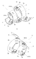
以下に図面を参照して本発明に係る管内移動装置について説明する。図1は管内移動装置の側面図であり、図2は管内移動装置の概略的な分解斜視図であり、図3は管内移動装置の斜視図であり、図4は管内移動装置を所定の軸方向に沿って見た図であり、図5は管内移動装置の駆動機構の配置状態を説明する図である。 The in-pipe moving apparatus according to the present invention will be described below with reference to the drawings. FIG. 1 is a side view of the in-pipe moving device, FIG. 2 is a schematic exploded perspective view of the in-pipe moving device, FIG. 3 is a perspective view of the in-pipe moving device, and FIG. FIG. 5 is a diagram for explaining the state of arrangement of the drive mechanism of the in-pipe movement apparatus.
図1〜図5に示すように、管内移動装置10は、螺旋体1と、螺旋体1に装着される複数の駆動機構3とを備える。管内移動装置10は、ガス管などの各種の管Pの内部を移動できるように構成されている。具体的には、管内移動装置10は、管Pの状態を確認及び検査するための機器(カメラ、検査機器など)を管Pの内部に送り込むために使用される。管内移動装置10が管Pの内部を長い距離にわたって移動している間には、管Pの内径が変化する箇所、管Pが曲っている箇所(エルボや分岐等)、管Pの断面形状が円形でなくなる箇所(例えば、プラグバルブ等)などが存在する。従って、それら移動の障害となり得る箇所を通過できる性能が管内移動装置10に要求される。つまり、管Pの内径の変化に応じて自身の外径を変化できるような性能、管Pの曲りに応じて自身が屈曲できるような性能、管Pの断面形状の変化に応じて自身の断面形状を変化できるような性能などが、管内移動装置10に要求される。
本発明に係る管内移動装置10は、上述したような要求を満たすものである。以下に、管内移動装置10が備える螺旋体1及び駆動機構3の構成について具体的に説明する。
As shown in FIGS. 1 to 5, the in-
The in-
螺旋体1は、弾性変形自在の長手部材2が、所定の軸Xの方向に沿って(つまり、軸Xの周りに)螺旋状に形成されたものである。本実施形態において、長手部材2は金属製の板状部材である。螺旋体1は、弾性変形自在であるので、あらゆる方向に屈曲できる。よって、管内移動装置10は、管Pの曲りに応じて自身を屈曲できる。加えて、螺旋体1は、軸Xの方向に変形して伸び縮み可能であり、例えば螺旋体1が軸Xの方向に伸びると螺旋体1は細くなる(つまり、螺旋径が小さくなる)。よって、管内移動装置10は、自身の外径を変えることができる。更に、螺旋体1は、円形以外の断面形状にも変形できる。従って、管内移動装置10は、管Pの断面形状に応じて自身の断面形状を変えることができる。
The
螺旋体1は、長手部材2の一方の面(外側部2b)が一様に螺旋体1の径方向外側(軸Xから離れる側)に向き且つ長手部材2の他方の面(内側部2c)が一様に螺旋体1の径方向内側(軸Xに近づく側)に向いた状態で螺旋状に形成されている。つまり、板状の長手部材2の一つの面(外側部2b)が一様に管Pの内面に対して対面するので、管内移動装置10が管Pの内部でスムーズな走行を行える。加えて、螺旋体1は、軸Xの方向に沿った端部の螺旋径が中央部Cの螺旋径よりも小さく形成されている。そのため、管内移動装置10が前進及び後進の何れの方向に移動するときでも、螺旋径の小さい方が先頭になる。つまり、螺旋体1が管Pの内部で引っ掛かり難くなっている。
In the
更に、螺旋体1は、螺旋体1が管Pの内部にないときの定常状態の最大螺旋径が、管Pの内径に対して等しいか又は大きくなるように形成されている。よって、螺旋体1が管Pの内部にあるとき、螺旋体1は螺旋径を大きくしようとする押圧力を管Pの内面に対して与える。従って、後述する駆動機構3の車輪3aは管Pの内面に押し付けられ、駆動力を管Pの内面に対して確実に与えることができる。
Further, the
管Pの状態を確認及び検査するための機器(カメラ、検査機器など)は、螺旋体1の進行方向先端部や、螺旋体1の中央部Cの空洞部分などに設置される。或いは、それらの機器を管内移動装置10で曳航してもよい。
Equipment (camera, inspection equipment, etc.) for confirming and inspecting the state of the tube P is installed at the leading end of the
複数の駆動機構3は、螺旋体1を一方向に進行させようとする駆動力を螺旋体1に与える。本実施形態において、駆動機構3は、車輪3aとその車輪3aを回転させるモータ3bとを有する。モータ3bにはケーブル4を介して給電される。駆動機構3は、車輪3aの一部が螺旋体1の径方向外側に突出する形態で螺旋体1に装着される。具体的には、車輪3aの一部は、長手部材2に形成されている孔部2aを内側部2cから外側部2bへ貫通して、螺旋体1の外側部2bよりも径方向外側に突出している。その結果、車輪3aは管Pの内面に確実に当接する。また、車輪3aの残部及びモータ3bは、板状の長手部材2の内側部2c(螺旋体1の径方向内側)に装着されている。ここで、螺旋体1の径方向内側とは、螺旋体1の外表面よりも内側(軸Xの側)のことである。このような構成を採用することで、螺旋体1の径方向外側に突出した車輪3aによって駆動機構3による駆動力を管Pの内面に与えつつ、螺旋体1の径方向内側に装着された駆動機構3のモータ3bなどが管Pに接触しないようにできる。
また、駆動機構3のモータ3bの回転方向を変えることで、管内移動装置10の前進及び後進を変更できる。モータ3bの回転方向の変更は、ケーブル4に接続されている電源の極性を変更する方法などがある。
The plurality of
Further, by changing the rotation direction of the
本実施形態では、各駆動機構3の駆動力の方向は、軸Xの方向に直交する方向に対して傾いている。つまり、図示するように、各駆動機構3の駆動力の方向は、軸Xの方向に対して一様に所定の傾き角θ1だけ傾いており、傾き角θ1は0°を含み90°(直交)を含まない。図示する例では、傾き角θ1は、0°<θ1<90°となっているので、管内移動装置10は回転しながら一方向に進む。この傾き角θ1は適宜設定可能である。但し、傾き角が0°(即ち、軸Xに平行)に近い程、管内移動装置10の進行速度は速く(管内移動装置10の回転速度は遅く)なり、この傾き角が90°(軸Xに直交)に近い程、管内移動装置10の進行速度は遅く(管内移動装置10の回転速度は速く)なる。
尚、上記傾き角が90°になると、管内移動装置10は一ヶ所で回転するだけになり、進行しなくなる。本実施形態の場合、移動機構が設けられている螺旋体1は管Pの内部形状に応じて変形するため、管内移動装置10が管Pの内部を進行している間に上記傾き角も変化し得る。そのため、螺旋体1が管Pの内部形状に応じて変化したとしても上記傾き角が90°とならないように、駆動機構3を螺旋体1に装着しておく必要がある。
In the present embodiment, the direction of the driving force of each
When the tilt angle is 90 °, the in-
図4に示すように、本実施形態では、駆動機構3は螺旋体1が1周する間に4個(即ち、90°間隔で)設けられている。駆動機構3の設置間隔が大きい場合(例えば、螺旋体1が1周する間に2個(即ち、180°間隔で)設けられている場合)には、駆動機構3と駆動機構3との間の螺旋体1が管Pの内面に接触して、管内移動装置10の移動を阻害する可能性がある。そのため、駆動機構3の設置間隔が少なすぎることは好ましくない。尚、本実施形態では駆動機構3の設置間隔が90°である場合を例示したが、120°間隔、60°間隔など、他の間隔で駆動機構3を設けてもよい。また、移動機構の設置間隔が螺旋体1の1周である360°の約数とならないような設置形態(50°間隔、100°間隔など)も可能である。
また、全ての車輪3aを駆動しないような運用形態も可能である。例えば、螺旋体1に対して従動輪を装着してもよい。
As shown in FIG. 4, in this embodiment, four
Moreover, the operation form which does not drive all the
次に、図6及び図7を参照して、管内移動装置10が管Pの内部を移動しているときの状態を説明する。
図6は、管Pの曲り部を管内移動装置10が移動しているときの状態である。管内移動装置10は、弾性変形自在の長手部材2を螺旋状にした螺旋体1で構成されているので、管Pの曲り状態に適応して自身が屈曲する。管内移動装置10の形状変化(この場合は「曲り」)は、螺旋体1の弾性力によって自動的に行われる。そのため、管内移動装置10の形状変化のために特別な制御機構は不要である。
Next, with reference to FIG. 6 and FIG. 7, a state when the in-
FIG. 6 shows a state where the in-
図7は、管Pの内径が変化している部位を管内移動装置10が移動しているときの状態である。螺旋体1は、軸Xの方向に沿った端部の螺旋径が中央部Cの螺旋径よりも小さく形成されているので、管Pの内径の小さい部分にその端部からスムーズに入り込むことができる。更に、螺旋体1が回転しながら進むので、例えばネジの先端が狭い部分に旋回しながら入り込んで行くように、螺旋体1の全体が管Pの奥の狭い部分に旋回しながら入り込んで行くことができる。このとき、本来の螺旋径が比較的大きい螺旋体1の中央部Cは、管Pの内径の変化に応じて自身の外径を変化させながら、管Pの内径の小さい部分に進入する。
FIG. 7 shows a state in which the in-
以上のように、管内移動装置10が備える螺旋体1は、弾性変形自在であるので、あらゆる方向に屈曲でき、軸Xの方向に沿って変形して伸び縮み可能であり、円形以外の断面形状にも変形できる。よって、管内移動装置10は、管Pの曲りに応じて自身を屈曲しながら管Pの内部を移動でき、伸び縮みすることで自身の外径を変えながら管Pの内部を移動でき、管Pの断面形状に応じて自身の断面形状を変えながら管Pの内部をスムーズに移動できる。
As described above, the
<別実施形態>
<1>
上記実施形態において、螺旋体1が軸Xの方向に沿って収縮するとき、螺旋状に形成された長手部材2同士が螺旋体1の径方向に重なる可能性がある。螺旋状に形成された長手部材2同士が径方向に重なると、螺旋体1の柔軟性が低下してしまう。そこで、本別実施形態おいて、螺旋体1に重なり規制手段5を設ける例を説明する。図8(a)及び図8(b)は、管内移動装置10の重なり規制手段5の構成を説明する図である。尚、図8(a)及び図8(b)では、螺旋状に形成された長手部材2の軸Xの方向の一方側のみに重なり規制手段5を設けた状態を図示しているが、軸Xの方向の両側に重なり規制手段5を設けてもよい。そのとき、螺旋状に形成された長手部材2の軸Xの方向の一方側と他方側とで、同じ形状の重なり規制手段5を設けてもよいし、別々の形状(例えば、図8(a)に示す径方向突出部材5Aと図8(b)に示す軸方向突出部材5B)の重なり規制手段5を設けてもよい。
<Another embodiment>
<1>
In the above embodiment, when the
図8(a)に示す重なり規制手段5は、螺旋状に形成された長手部材2に対して、螺旋体1の径方向内側(即ち、軸Xに近づく側)に向かう径方向突出部材5Aを用いて形成される。図8(b)に示す径方向突出部材5Aは細長い短冊状の部材であるが、単なる棒状や幅の広い板状の部材などの他の形状であってもよい。ある程度の硬さがあれば、径方向突出部材5Aの材質は適宜選択できる。この場合、螺旋体1が軸Xの方向に沿って収縮するとしても、長手部材2は、旋回して軸Xの方向に隣接した位置にある長手部材2に装着された径方向突出部材5A(重なり規制手段5)に当接する可能性は高いが、軸Xの方向に沿って隣接する長手部材2同士が径方向に重なる可能性は低くなる。
The overlap regulating means 5 shown in FIG. 8A uses a
図8(b)に示す重なり規制手段5は、螺旋状に形成された長手部材2に対して、軸Xの方向に向かう軸方向突出部材5Bを用いて形成される。図8(b)に例示する軸方向突出部材5Bは半円状の板状部材の直径部分を長手部材2に装着した形態であるが、四角形や三角形などの他の形状の部材で形成してもよい。ある程度の硬さがあれば、軸方向突出部材5Bの材質は適宜選択できる。この場合、螺旋体1が軸Xの方向に沿って収縮するとしても、長手部材2は、旋回して軸Xの方向に隣接した位置にある長手部材2に装着された軸方向突出部材5B(重なり規制手段5)に当接する可能性は高いが、軸Xの方向に沿って隣接する長手部材2同士が径方向に重なる可能性は低くなる。更に、図8(b)に示すように、螺旋状に形成された長手部材2から軸Xの方向の一方側に駆動機構3の一部がはみ出すような場合、そのはみ出した駆動機構3を保護するように軸方向突出部材5B(重なり規制手段5)を設けてもよい。
The overlap regulating means 5 shown in FIG. 8B is formed by using an axial projecting
<2>
上記実施形態において、駆動機構3の構成を改変してもよい。例えば、車輪3aの代わりに無限軌道(図示せず)を用いてもよい。この場合、少なくとも無限軌道履帯の一部が螺旋体1の径方向外側に突出する形態で駆動機構3が螺旋体1に装着される。或いは、図9に示すように、螺旋体1に装着される振動器と、その振動器に対して設定方向に配向して装着された剛毛とを有する駆動機構3を用いてもよい。この場合、少なくとも剛毛の一部が螺旋体1の径方向外側に突出する形態で駆動機構3が螺旋体1に装着される。図9に示す例では、剛毛は螺旋体1の接線方向に対して角θ2だけ傾いて配向した状態で振動器に装着されている。よって、ケーブル4から供給される電力で振動器が振動するとその振動は剛毛に伝わり、剛毛の振動と管Pの内面との間の作用・反作用により螺旋体1が図示する矢印方向に回転する。
<2>
In the above embodiment, the configuration of the
<3>
上記実施形態において、螺旋体1を構成する長手部材2は、弾性変形自在であれば樹脂製などの金属以外の材料で製造してもよい。更に、長手部材2は板状でなくてもよい。例えば、長手部材2の断面が円形又は楕円形などの他の形状でもよい。
<3>
In the said embodiment, you may manufacture the
本発明に係る管内移動装置は、ガス管などの様々な管の状態を管内から検査するための機器を管内に送り込むときに利用できる。 The in-pipe moving device according to the present invention can be used when a device for inspecting the state of various pipes such as a gas pipe from the inside of the pipe is sent into the pipe.
1 螺旋体
2 長手部材
2a 孔部
2b 外側部
2c 内側部
3 駆動機構
3a 車輪
3b モータ
5 重なり規制手段
5A 径方向突出部材
5B 軸方向突出部材
10 管内移動装置
P 管
E 端部
C 中央部
DESCRIPTION OF
Claims (7)
弾性変形自在の長手部材が、所定の軸方向に沿って螺旋状に形成される螺旋体と、
前記螺旋体に装着され、前記螺旋体を一方向に進行させようとする駆動力を前記螺旋体に与える複数の駆動機構と、を備え、
前記長手部材が板状部材であり、
前記螺旋体は、前記板状部材の一方の面が一様に前記螺旋体の径方向外側に向き且つ前記板状部材の他方の面が一様に前記螺旋体の径方向内側に向いた状態で螺旋状に形成され、
前記駆動機構は、車輪と当該車輪を回転させるモータとを有し、前記車輪の一部は、前記板状部材である前記長手部材に形成されている孔部を内側部から外側部へ貫通して、前記螺旋体の外側部よりも径方向外側に突出する形態で前記螺旋体の径方向内側に装着されている管内移動装置。 An in-pipe moving device that can move in a pipe,
A spiral body in which an elastically deformable longitudinal member is spirally formed along a predetermined axial direction;
A plurality of drive mechanisms attached to the spiral body and applying a driving force to the spiral body to drive the spiral body in one direction;
The longitudinal member is a plate-like member;
The spiral body is spiral with one surface of the plate-shaped member uniformly facing radially outward of the spiral body and the other surface of the plate-shaped member uniformly facing radially inward of the spiral body. Formed into
The drive mechanism includes a wheel and a motor that rotates the wheel, and a part of the wheel penetrates a hole formed in the longitudinal member, which is the plate-like member, from an inner part to an outer part. An in- pipe moving device that is mounted on the radially inner side of the spiral body in a form that protrudes radially outward from the outer portion of the spiral body .
Priority Applications (1)
| Application Number | Priority Date | Filing Date | Title |
|---|---|---|---|
| JP2009163061A JP5498068B2 (en) | 2009-07-09 | 2009-07-09 | In-pipe moving device |
Applications Claiming Priority (1)
| Application Number | Priority Date | Filing Date | Title |
|---|---|---|---|
| JP2009163061A JP5498068B2 (en) | 2009-07-09 | 2009-07-09 | In-pipe moving device |
Publications (2)
| Publication Number | Publication Date |
|---|---|
| JP2011016467A JP2011016467A (en) | 2011-01-27 |
| JP5498068B2 true JP5498068B2 (en) | 2014-05-21 |
Family
ID=43594616
Family Applications (1)
| Application Number | Title | Priority Date | Filing Date |
|---|---|---|---|
| JP2009163061A Expired - Fee Related JP5498068B2 (en) | 2009-07-09 | 2009-07-09 | In-pipe moving device |
Country Status (1)
| Country | Link |
|---|---|
| JP (1) | JP5498068B2 (en) |
Families Citing this family (5)
| Publication number | Priority date | Publication date | Assignee | Title |
|---|---|---|---|---|
| JP5415984B2 (en) * | 2010-02-09 | 2014-02-12 | 大阪瓦斯株式会社 | In-pipe moving device |
| JP5415985B2 (en) * | 2010-02-09 | 2014-02-12 | 大阪瓦斯株式会社 | In-pipe moving device |
| JP5432794B2 (en) * | 2010-03-29 | 2014-03-05 | 大阪瓦斯株式会社 | Magnetizing apparatus and in-pipe moving apparatus |
| JP5654903B2 (en) * | 2011-03-04 | 2015-01-14 | 大阪瓦斯株式会社 | In-pipe moving device |
| JP5901380B2 (en) * | 2012-03-26 | 2016-04-06 | 大阪瓦斯株式会社 | Self-propelled aircraft |
Family Cites Families (3)
| Publication number | Priority date | Publication date | Assignee | Title |
|---|---|---|---|---|
| JP2513927Y2 (en) * | 1990-07-19 | 1996-10-09 | 日本ゼオン株式会社 | Lumen dilatation device |
| JP2549989B2 (en) * | 1994-04-25 | 1996-10-30 | 管清工業株式会社 | In-service self-propelled device |
| JP2000052282A (en) * | 1998-08-10 | 2000-02-22 | Agriculture Forestry & Fisheries Technical Information Society | Robot travelling in t-shaped branch pipe and its directional control method |
-
2009
- 2009-07-09 JP JP2009163061A patent/JP5498068B2/en not_active Expired - Fee Related
Also Published As
| Publication number | Publication date |
|---|---|
| JP2011016467A (en) | 2011-01-27 |
Similar Documents
| Publication | Publication Date | Title |
|---|---|---|
| JP5498068B2 (en) | In-pipe moving device | |
| JP6301078B2 (en) | Pipe moving device | |
| EP1714751B1 (en) | Deformable structure and cable support system | |
| JP5602737B2 (en) | Pipe making machine and pipe making method | |
| JP5784387B2 (en) | Metal pipe bending machine | |
| JP2004523196A5 (en) | ||
| JP5415985B2 (en) | In-pipe moving device | |
| JP2009044809A (en) | Slewing type cable protective guidance device | |
| US8887343B2 (en) | System for propelling a coil clad hose and method thereof | |
| EP3892526A1 (en) | Pipe interior inspection robot | |
| KR101494784B1 (en) | Small diameter pipeline internal inspection robot | |
| JP2011052408A (en) | Guide device for tapered pile | |
| JP4794336B2 (en) | Automated traveling robot | |
| JP5569029B2 (en) | Cable support device for industrial robot with flexible guide | |
| JP2010070904A (en) | Drill bit shaft structure of drilling unit | |
| JP6267327B2 (en) | Pipe making apparatus and pipe making method using the same | |
| JP2020055094A (en) | Electrically-driven fastening device | |
| ES2703701T3 (en) | Orbital welding device with adjustable running gear | |
| JP5654903B2 (en) | In-pipe moving device | |
| CN110325333B (en) | Industrial robot and device for transferring a medium from a robot to a tool | |
| JP5901380B2 (en) | Self-propelled aircraft | |
| WO2015182556A1 (en) | Parallel link mechanism and link operation device | |
| JP5814079B2 (en) | In-pipe moving device | |
| JP2012081528A (en) | Articulated robot | |
| JP2020146621A (en) | In-pipeline travel device |
Legal Events
| Date | Code | Title | Description |
|---|---|---|---|
| A621 | Written request for application examination |
Free format text: JAPANESE INTERMEDIATE CODE: A621 Effective date: 20120531 |
|
| A977 | Report on retrieval |
Free format text: JAPANESE INTERMEDIATE CODE: A971007 Effective date: 20130604 |
|
| A131 | Notification of reasons for refusal |
Free format text: JAPANESE INTERMEDIATE CODE: A131 Effective date: 20130613 |
|
| A521 | Written amendment |
Free format text: JAPANESE INTERMEDIATE CODE: A523 Effective date: 20130801 |
|
| TRDD | Decision of grant or rejection written | ||
| A01 | Written decision to grant a patent or to grant a registration (utility model) |
Free format text: JAPANESE INTERMEDIATE CODE: A01 Effective date: 20140206 |
|
| A61 | First payment of annual fees (during grant procedure) |
Free format text: JAPANESE INTERMEDIATE CODE: A61 Effective date: 20140307 |
|
| R150 | Certificate of patent or registration of utility model |
Ref document number: 5498068 Country of ref document: JP Free format text: JAPANESE INTERMEDIATE CODE: R150 |
|
| LAPS | Cancellation because of no payment of annual fees |