JP5495664B2 - Solid production method - Google Patents
Solid production method Download PDFInfo
- Publication number
- JP5495664B2 JP5495664B2 JP2009184492A JP2009184492A JP5495664B2 JP 5495664 B2 JP5495664 B2 JP 5495664B2 JP 2009184492 A JP2009184492 A JP 2009184492A JP 2009184492 A JP2009184492 A JP 2009184492A JP 5495664 B2 JP5495664 B2 JP 5495664B2
- Authority
- JP
- Japan
- Prior art keywords
- extraction
- liquid
- solid
- fluid supply
- fluid
- Prior art date
- Legal status (The legal status is an assumption and is not a legal conclusion. Google has not performed a legal analysis and makes no representation as to the accuracy of the status listed.)
- Active
Links
Images


Description
本発明は、晶析方法、重合方法等の固体生成方法に関する。 The present invention relates to a solid production method such as a crystallization method or a polymerization method.
固体生成手段内で原料を含む液を処理して原料に由来する固体を含む液を得た後、固体生成手段内の固体を含む液を抜出流路から抜き出す際に、固体が抜出流路に詰まることがある。 After the liquid containing the raw material is processed in the solid production means to obtain the liquid containing the solid derived from the raw material, the solid is extracted when the liquid containing the solid in the solid production means is extracted from the extraction flow path. The road may become clogged.
例えば、(メタ)アクリル酸の精製を目的に、晶析装置内で(メタ)アクリル酸溶液を冷却して、(メタ)アクリル酸の結晶を含むスラリーを得ることが行われる(特許文献1)。そして、晶析装置内の、(メタ)アクリル酸の結晶を含むスラリーを抜出流路から抜き出す際に、(メタ)アクリル酸の結晶が抜出流路に詰まることがある。なお、本明細書において(メタ)アクリル酸とは、アクリル酸またはメタクリル酸をいうものとする。 For example, for the purpose of purifying (meth) acrylic acid, a (meth) acrylic acid solution is cooled in a crystallizer to obtain a slurry containing crystals of (meth) acrylic acid (Patent Document 1). . When the slurry containing (meth) acrylic acid crystals in the crystallizer is extracted from the extraction flow path, the (meth) acrylic acid crystals may be clogged in the extraction flow path. In this specification, (meth) acrylic acid means acrylic acid or methacrylic acid.
また、重合装置内で、水にモノマーを懸濁させた懸濁液を加熱し、モノマーを重合させて、ポリマーを含むスラリーを得た後、重合装置内の、ポリマーを含むスラリーを抜出流路から抜き出す際に、ポリマーが抜出流路に詰まることがある。 In addition, the suspension of the monomer in water is heated in the polymerization apparatus to polymerize the monomer to obtain a polymer-containing slurry, and then the polymer-containing slurry in the polymerization apparatus is discharged. When extracting from the channel, the polymer may become clogged in the extraction channel.
本発明は、固体生成手段内の固体を含む液を抜出流路から抜き出す際に、固体が抜出流路に詰まりにくい固体生成システムおよび固体生成方法を提供する。 The present invention provides a solid generation system and a solid generation method in which solids are less likely to be clogged in an extraction channel when a liquid containing solids in a solid generation unit is extracted from the extraction channel.
本発明の固体生成方法は、固体生成手段内で原料を含む液(A)を処理して原料に由来する固体を含む液(B)を得る工程と、固体生成手段から固体を含む液(B)を抜出流路から抜き出す工程とを有する固体生成方法において、固体生成手段から固体を含む液(B)を抜き出す前、および/または、抜き出す間、抜出流路に、抜出流路の途中に合流する流体供給流路から流体(C)を供給し、流体供給流路との合流点よりも下流側の抜出流路に設けられた抜出弁および流体供給流路に設けられた流体供給弁の開閉を、抜出弁および流体供給弁に接続された制御手段によって下記(I)〜(IV)のように制御することを特徴とする。
(I)抜出弁については、下記条件(a)を満足する開放と、下記条件(b)を満足する完全閉止ないし略閉止とを繰り返す。
条件(a):固体生成手段からの固体を含む液(B)の抜き出し速度Ve(kg/時間)が固体生成手段への原料を含む液(A)の平均供給速度Vs AV の200%以上となる。流体(C)として液体を用いる場合には、平均供給速度Vs AV は、流体(C)中の液体を含んだ平均供給速度とする。
条件(b):固体生成手段からの固体を含む液(B)の抜き出し速度Ve(kg/時間)が固体生成手段への原料を含む液(A)の平均供給速度Vs AV の0〜10%となる。
(II)前記条件(a)を満足する抜出弁の開放の頻度を、10分あたり1回以上とする。
(III)前記条件(a)を満足する抜出弁の開放の合計時間を、原料を含む液(A)の処理開始から処理終了までの時間の0.1〜20%とする。
(IV)流体供給弁については、抜出弁の開放の1〜60秒前から抜出弁の開放まで、または、抜出弁の開放の1〜60秒前から抜出弁の完全閉止ないし略閉止までの間は開放し、それ以外は閉止する。
なお、本明細書において平均供給速度(平均抜き出し速度)は、1時間あたりの供給量(抜き出し量)をいい、単なる供給速度(抜き出し速度)は、ある時点における瞬間的な流量(すなわち瞬間速度)をいうものとする。
The solid production method of the present invention comprises a step of treating a liquid (A) containing a raw material in a solid production means to obtain a liquid (B) containing a solid derived from the raw material, and a liquid containing a solid from the solid production means (B ) From the extraction flow path before the liquid (B) containing the solid from the solid generation means and / or during the extraction, the extraction flow path is connected to the extraction flow path. The fluid (C) is supplied from the fluid supply channel that joins in the middle, and is provided in the extraction valve and the fluid supply channel provided in the extraction channel on the downstream side of the junction with the fluid supply channel. The opening and closing of the fluid supply valve is controlled by the control means connected to the extraction valve and the fluid supply valve as described in (I) to (IV) below .
(I) For the extraction valve, the opening satisfying the following condition (a) and the complete closing or substantially closing satisfying the following condition (b) are repeated.
Condition (a): Solid withdrawal speed Ve (kg / hour) of liquid containing solids from generation means (B) is more than 200% of the average feed rate Vs AV of the liquid (A) containing the material to the solid generating means and Become. When using a liquid as the fluid (C), the average feed rate Vs AV is the average feed rate including the liquid in the fluid (C).
Condition (b): The extraction speed Ve (kg / hour) of the liquid (B) containing the solid from the solid production means is 0 to 10% of the average supply speed Vs AV of the liquid (A) containing the raw material to the solid production means It becomes.
(II) The frequency of opening the extraction valve that satisfies the condition (a) is set to be once or more per 10 minutes.
(III) The total time for opening the extraction valve that satisfies the condition (a) is set to 0.1 to 20% of the time from the start of processing of the liquid (A) containing the raw material to the end of processing.
(IV) For the fluid supply valve, from 1 to 60 seconds before opening the extraction valve to the opening of the extraction valve or from 1 to 60 seconds before opening the extraction valve, Open until closing and close otherwise.
In this specification, the average supply speed (average extraction speed) refers to the supply amount (extraction amount) per hour, and the mere supply speed (extraction speed) is the instantaneous flow rate (ie, instantaneous speed) at a certain point in time. It shall be said.
本発明の固体生成方法においては、原料を含む液(A)が、アクリル酸溶液、またはアクリル酸の結晶を含むスラリーであり、固体を含む液(B)が、アクリル酸の結晶を含むスラリーであることが好ましい。この場合、流体(C)は、アクリル酸溶液であることが好ましい。
本発明の固体生成方法においては、原料を含む液(A)が、メタクリル酸溶液、またはメタクリル酸の結晶を含むスラリーであり、固体を含む液(B)が、メタクリル酸の結晶を含むスラリーであることが好ましい。この場合、流体(C)は、メタクリル酸溶液であることが好ましい。
In the solid production method of the present invention, the liquid (A) containing the raw material is an acrylic acid solution or a slurry containing acrylic acid crystals, and the liquid (B) containing a solid is a slurry containing acrylic acid crystals. Preferably there is. In this case, the fluid (C) is preferably an acrylic acid solution.
In the solid production method of the present invention, the liquid (A) containing the raw material is a methacrylic acid solution or a slurry containing methacrylic acid crystals, and the liquid (B) containing a solid is a slurry containing methacrylic acid crystals. Preferably there is. In this case, the fluid (C) is preferably a methacrylic acid solution.
流体(C)として、さらに不活性ガスを供給することが好ましい。 It is preferable to further supply an inert gas as the fluid (C).
本発明の固体生成システムによれば、固体生成手段内の固体を含む液を抜出流路から抜き出す際に、固体が抜出流路に詰まりにくい。
本発明の固体生成方法によれば、固体生成手段内の固体を含む液を抜出流路から抜き出す際に、固体が抜出流路に詰まりにくい。
According to the solid production system of the present invention, when the liquid containing the solid in the solid production means is extracted from the extraction flow path, the solid is not easily clogged in the extraction flow path.
According to the solid production method of the present invention, when the liquid containing the solid in the solid production means is extracted from the extraction flow path, the solid is not easily clogged in the extraction flow path.
(固体生成システム)
図1は、本発明の固体生成システムの基本構成を示す構成図である。固体生成システム1は、原料を含む液(A)を処理して原料に由来する固体を含む液(B)を得る固体生成手段2と;固体生成手段2から固体を含む液(B)を抜き出す抜出流路3と;抜出流路3に設けられた抜出弁4と;固体生成手段2と抜出弁4との間の抜出流路3に合流して流体(C)を供給する流体供給流路5と;流体供給流路5に設けられた流体供給弁6と;抜出弁4および流体供給弁6の開閉を制御する制御手段7とを具備する。ただし、流体(C)を供給する流体供給流路5は必要に応じて抜出弁4の下流側の閉塞を抑制するために、抜出弁4の下流側にも併せて接続してもよい。
(Solid production system)
FIG. 1 is a configuration diagram showing a basic configuration of a solid production system of the present invention. The solid generation system 1 processes the liquid (A) containing the raw material to obtain the liquid (B) containing the solid derived from the raw material; and the liquid (B) containing the solid is extracted from the solid generation means 2 The extraction flow path 3; the
固体生成システム1としては、晶析システム、重合システム等が挙げられる。
固体生成システム1が晶析システムの場合の固体生成手段2としては、晶析装置等が挙げられる。
固体生成システム1が重合システムの場合の固体生成手段2としては、重合装置等が挙げられる。
抜出弁4および流体供給弁6としては、電磁弁、電動弁、エアー駆動弁等が挙げられる。
Examples of the solid generation system 1 include a crystallization system and a polymerization system.
As the solid production | generation means 2 in case the solid production | generation system 1 is a crystallization system, a crystallization apparatus etc. are mentioned.
Examples of the solid generation means 2 when the solid generation system 1 is a polymerization system include a polymerization apparatus.
Examples of the
制御手段7は、処理部(図示略)とインターフェイス部(図示略)と記憶部(図示略)とを具備する。
インターフェイス部は、抜出弁4および流体供給弁6と、処理部との間を電気的に接続するものである。
処理部は、記憶部に記憶された所定のインターバル、供給速度、抜き出し速度等に基づいて抜出弁4および流体供給弁6のそれぞれの開閉を制御するものである。
The control means 7 includes a processing unit (not shown), an interface unit (not shown), and a storage unit (not shown).
The interface unit is for electrically connecting the
The processing unit controls the opening and closing of the
なお、該処理部は専用のハードウエアにより実現されるものであってもよく、また、該処理部はメモリおよび中央演算装置(CPU)によって構成され、処理部の機能を実現するためのプログラムをメモリにロードして実行することによりその機能を実現させるものであってもよい。
また、制御手段7には、周辺機器として、入力装置、表示装置等が接続されるものとする。ここで、入力装置とは、ディスプレイタッチパネル、スイッチパネル、キーボード等の入力デバイスのことをいい、表示装置とは、CRT、液晶表示装置等のことをいう。
The processing unit may be realized by dedicated hardware, and the processing unit is configured by a memory and a central processing unit (CPU), and a program for realizing the function of the processing unit is provided. The function may be realized by loading it into a memory and executing it.
In addition, an input device, a display device, and the like are connected to the
(固体生成方法)
つぎに、固体生成システム1を用いた固体生成方法について説明する。
まず、固体生成手段2内で原料を含む液(A)を処理して原料に由来する固体を含む液(B)を得る。
ついで、固体生成手段2内の固体を含む液(B)を抜出流路3から抜き出す。
(Solid production method)
Next, a solid production method using the solid production system 1 will be described.
First, the liquid (A) containing a raw material is processed in the solid production | generation means 2, and the liquid (B) containing the solid originating in a raw material is obtained.
Subsequently, the liquid (B) containing the solid in the solid production | generation means 2 is extracted from the extraction flow path 3. FIG.
本発明においては、固体生成手段2から固体を含む液(B)を抜き出す前、および/または、抜き出す間、抜出流路3に、流体供給流路5から流体(C)を供給することに特徴がある。固体を含む液(B)を抜き出す前および抜き出す間、抜出流路3に流体(C)を供給し、抜出流路3から固体生成手段2に向かって流体(C)を逆流させることによって、抜出流路3の入口および内部における固体の詰まりを十分に抑制できる。
In the present invention, the fluid (C) is supplied from the
固体生成方法が、晶析方法のように、原料を含む液(A)を固体生成手段2に連続的に(場合によっては断続的に)供給し、固体を含む液(B)を固体生成手段2から断続的に抜き出す方法の場合、固体を含む液(B)の抜き出しの開始ならびに終了、および流体(C)の供給の開始ならびに終了は、制御手段7の記憶部に記憶されたインターバル、供給速度、抜き出し速度等に基づいて、制御手段7の制御部により抜出弁4および流体供給弁6のそれぞれの開閉を下記(I)〜(IV)のように制御することにより行うことが好ましい。
In the solid production method, the liquid (A) containing the raw material is continuously (in some cases intermittently) supplied to the solid production means 2 as in the crystallization method, and the liquid (B) containing the solid is supplied to the solid production means. In the case of the method of intermittently extracting from the
(I)抜出弁4については、下記条件(a)を満足する開放と、下記条件(b)を満足する完全閉止ないし略閉止とを繰り返す。
条件(a):固体生成手段2からの固体を含む液(B)の抜き出し速度Ve(kg/時間)が固体生成手段2への原料を含む液(A)の平均供給速度VsAVの200%以上となる。流体(C)として液体を用いる場合には、平均供給速度VsAVは、流体(C)中の液体を含んだ平均供給速度とする。
条件(b):固体生成手段2からの固体を含む液(B)の抜き出し速度Ve(kg/時間)が固体生成手段2への原料を含む液(A)の平均供給速度VsAVの0〜10%となる。
(II)条件(a)を満足する抜出弁4の開放の頻度を、10分あたり1回以上とする。
(III)条件(a)を満足する抜出弁4の開放の合計時間を、原料を含む液(A)の処理開始から処理終了までの時間の0.1〜20%とする。
(IV)流体供給弁6については、抜出弁4の開放の1〜60秒前から抜出弁4の開放まで開放し、それ以外は閉止してもよく、抜出弁4の開放の1〜60秒前から抜出弁4の開放まで、および抜出弁4の開放から抜出弁4の完全閉止ないし略閉止までの間は開放し、それ以外は閉止してもよい。
(I) About the
Condition (a): The extraction speed Ve (kg / hour) of the liquid (B) containing the solid from the solid production means 2 is 200% of the average supply speed Vs AV of the liquid (A) containing the raw material to the solid production means 2 That's it. When using a liquid as the fluid (C), the average feed rate Vs AV is the average feed rate including the liquid in the fluid (C).
Condition (b): extracting speed Ve of the liquid containing solids from the solid-state generator 2 (B) (kg / time) 0 average feed rate Vs AV of the liquid (A) containing the material to the solid generating means 2 10%.
(II) The frequency of opening the
(III) The total opening time of the
(IV) The
条件(a)を満足する開放と、条件(b)を満足する完全閉止ないし略閉止とを繰り返すことによって、固体を含む液(B)を連続的に一定の抜き出し速度で抜き出す場合に比べ、抜出流路3における固体を含む液(B)の流れにメリハリが付き、これにより抜出流路3の入口および内部に付着あるいは滞留した固体が押し出され、抜出流路3の入口および内部における固体の詰まりを十分に抑制できる。 By repeating the opening satisfying the condition (a) and the complete closing or substantially closing satisfying the condition (b), the liquid (B) containing the solid is continuously extracted at a constant extraction speed. The flow of the liquid (B) containing the solid in the outlet flow path 3 is sharpened, thereby pushing out the solid adhering or staying in the inlet flow path 3 and in the outlet flow path 3. Solid clogging can be sufficiently suppressed.
条件(a)を満足する開放の頻度を10分あたり1回以上とすることによって、抜出流路3の入口および内部に付着あるいは滞留する固体の量を抑えることができる。 By setting the frequency of opening satisfying the condition (a) at least once per 10 minutes, the amount of solid adhering or staying at the inlet and inside of the extraction flow path 3 can be suppressed.
抜出弁4の開放の合計時間を、原料を含む液(A)の処理開始から処理終了までの時間の0.1%以上とすることにより、所定の量を安定的に抜き出せる。
抜出弁4の開放の合計時間を、原料を含む液(A)の処理開始から処理終了までの時間の20%以下とすることにより、抜出流路3の径を大きくできるため、抜出流路3の閉塞の頻度を少なくできる。
By setting the total opening time of the
By making the total opening time of the
流体供給弁6の開放開始を、抜出弁4の開放の1秒前およびそれ以前に開始することにより、固体を含む液(B)を抜き出す前および抜き出し開始直後の、抜出流路3における固体の詰まりを取り除き、抜出流路3の閉塞を十分に抑制できる。
流体供給弁6の開放開始を、抜出弁4の開放の60秒前およびそれ以降に開始することにより、流体(C)の流量が抑えられる。抜出流路3の閉塞を抑制できる範囲であれば、流体(C)の流量は低く抑える方が好ましい。
流体供給弁6を、抜出弁4の開放から抜出弁4の完全閉止ないし略閉止までの間、開放することにより、固体を含む液(B)を抜き出している間の、抜出流路3における固体の詰まりを十分に抑制できる。
By starting the opening of the
By starting the opening of the
The extraction flow path during the extraction of the liquid (B) containing the solid by opening the
なお、前記(I)〜(III)の範囲内で、固体生成手段2からの固体を含む液(B)の抜き出し速度Ve(kg/時間)が固体生成手段2への原料を含む液(A)の平均供給速度VsAVの10%超200%未満となるような抜出弁4の開放を適宜行ってもよい。
In addition, within the range of said (I)-(III), the extraction speed | velocity Ve (kg / hour) of the liquid (B) containing the solid from the solid production | generation means 2 is the liquid (A average
(晶析システム)
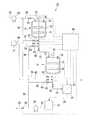
図2は、本発明の固体生成システムの一実施形態である、晶析システムの一例を示す構成図である。晶析システム10は、原料を含む液(A)を冷却して原料の晶析物を含む液(B)を得る第1の晶析装置12と;原料を含む液(A)を冷却して原料の晶析物を含む液(B)を得る第2の晶析装置14と;原料の晶析物を含む液(B)を原料の晶析物とろ液とに分離する固液分離装置16と;ろ液を貯留するろ液タンク18と;原料を含む液(A)を第1の晶析装置12に供給する原料供給流路20と;原料の晶析物を含む液(B)を第1の晶析装置12から抜き出し、原料を含む液(A)として第2の晶析装置14に供給する第1の抜出流路22と;原料の晶析物を含む液(B)を第2の晶析装置14から抜き出し、固液分離装置16に供給する第2の抜出流路24と;固液分離装置16から原料の晶析物を晶析システム10の後段へ移送する移送装置26と;固液分離装置16からろ液をろ液タンク18へ移送する移送流路28と;ろ液タンク18からろ液を、原料を含む液(A)として晶析システム10よりも前段に返送する返送流路30と;原料供給流路20から分岐し、第1の抜出流路22の途中に原料を含む液(A)を流体(C)として供給する第1の流体供給流路32と;ガスタンク33から第1の抜出流路22の途中にガスを流体(C)として供給する第2の流体供給流路34と;返送流路30から分岐し、第1の抜出流路22の途中にろ液を流体(C)として供給する第3の流体供給流路36と;第1の流体供給流路32から分岐し、第2の抜出流路24の途中に原料を含む液(A)を流体(C)として供給する第4の流体供給流路38と;第2の流体供給流路34から分岐し、第2の抜出流路24の途中にガスを流体(C)として供給する第5の流体供給流路40と;第3の流体供給流路36から分岐し、第2の抜出流路24の途中にろ液を流体(C)として供給する第6の流体供給流路42と;第1の流体供給流路32が分岐する位置よりも下流側の原料供給流路20の途中に設けられた原料供給弁44と;第1の流体供給流路32、第2の流体供給流路34および第3の流体供給流路36が合流する位置よりも下流側の第1の抜出流路22の途中に設けられた第1の抜出弁46と;第4の流体供給流路38、第5の流体供給流路40および第6の流体供給流路42が合流する位置よりも下流側の第2の抜出流路24の途中に設けられた第2の抜出弁48と;第3の流体供給流路36が分岐する位置よりも下流側の返送流路30の途中に設けられた返送弁50と;第4の流体供給流路38が分岐する位置よりも下流側の第1の流体供給流路32の途中に設けられた第1の流体供給弁52と;第5の流体供給流路40が分岐する位置よりも下流側の第2の流体供給流路34の途中に設けられた第2の流体供給弁54と;第6の流体供給流路42が分岐する位置よりも下流側の第3の流体供給流路36の途中に設けられた第3の流体供給弁56と;第4の流体供給流路38の途中に設けられた第4の流体供給弁58と;第5の流体供給流路40の途中に設けられた第5の流体供給弁60と;第6の流体供給流路42の途中に設けられた第6の流体供給弁62と;第1の流体供給流路32が分岐する位置よりも上流側の原料供給流路20の途中に設けられた原料供給ポンプ64と;第3の流体供給流路36が分岐する位置よりも上流側の返送流路30の途中に設けられた返送ポンプ66と;前記各弁の開閉を制御する制御手段68とを具備する。
第1の抜出流路22への流体(C)の供給箇所は、第1の抜出弁46よりも上流側が好ましく、第2の抜出流路24への流体(C)の供給箇所は、第2の抜出弁48よりも上流側が好ましい。ただし、流体(C)を供給する各ライン(32、34、36、38、40、42)は必要に応じて抜出弁(46、48)の下流側の閉塞を抑制するために、一部、抜出弁(46、48)の下流側にも併せて接続してもよい。
(Crystallization system)
FIG. 2 is a configuration diagram showing an example of a crystallization system which is an embodiment of the solid production system of the present invention. The
The supply location of the fluid (C) to the first
第1の晶析装置12および第2の晶析装置14は、それぞれ、晶析槽70と;晶析槽70の外側から晶析槽70およびその内部を冷却するジャケット72と、晶析槽70の内部を撹拌する撹拌翼74を有する撹拌機76と、晶析槽70内の液面の高さを検出する液面検出手段78とを具備する。液面検出手段78は、制御手段68に電気的に接続される。液面検出手段78としては、超音波センサ、フロート式センサ、圧力式センサ、静電容量式センサ等が挙げられる。
The
固液分離装置16としては、ベルト式脱水機、ドラム式脱水機、遠心脱水機等が挙げられる。
移送装置26としては、スクリューフィーダ、ベルトコンベア等が挙げられる。
各弁としては、電磁弁、電動弁、エアー駆動弁等が挙げられる。
Examples of the solid-
Examples of the
Examples of each valve include an electromagnetic valve, a motor operated valve, and an air driven valve.
制御手段68は、処理部(図示略)とインターフェイス部(図示略)と記憶部(図示略)とを具備する。
インターフェイス部は、前記各弁ならびに液面検出手段78と処理部との間を電気的に接続するものである。
処理部は、記憶部に記憶された所定のインターバル、供給速度、抜き出し速度等に基づいて前記各弁のそれぞれの開閉を制御するものである。
The control means 68 includes a processing unit (not shown), an interface unit (not shown), and a storage unit (not shown).
The interface unit electrically connects the valves and the liquid
The processing unit controls the opening and closing of each of the valves based on a predetermined interval, supply speed, extraction speed, and the like stored in the storage unit.
(晶析方法)
つぎに、晶析システム10を用いた晶析方法について説明する。
まず、原料供給弁44を開き、原料供給ポンプ64を駆動させて、原料供給流路20経由で原料を含む液(A)を第1の晶析装置12に、1時間あたりの供給量が所定量となるように連続的に(場合によっては断続的に)供給する。流体(C)として液体を用いる場合には、流体(C)中の液体量も考慮して所定流量となるようにする。
第1の晶析装置12内で、原料を含む液(A)を冷却して原料の晶析物を含む液(B)を得る。
所定のインターバルで第1の抜出弁46の開閉や抜出量の調整を行い、第1の抜出流路22経由で原料の晶析物を含む液(B)を第1の晶析装置12から後述する条件(a1)を満足するように断続的に抜き出し、原料を含む液(A)として第2の晶析装置14に断続的に供給する。
(Crystallization method)
Next, a crystallization method using the
First, the raw
In the
Opening and closing of the
第2の晶析装置14内で、原料を含む液(A)を冷却して原料の晶析物を含む液(B)を得る。
所定のインターバルで第2の抜出弁48の開閉や抜出量の調整を行い、第2の抜出流路24経由で原料の晶析物を含む液(B)を第2の晶析装置14から後述する条件(a2)を満足するように断続的に抜き出し、固液分離装置16に断続的に供給する。
In the
The
固液分離装置16内で、原料の晶析物を含む液(B)を原料の晶析物とろ液とに分離しながら、移送装置26によって、固液分離装置16から原料の晶析物を晶析システム10の後段へ移送し、かつ移送流路28経由で、固液分離装置16からろ液をろ液タンク18へ移送する。
必要に応じて、返送弁50を開き、返送ポンプ66を駆動させて、返送流路30経由でろ液タンク18からろ液を、原料を含む液(A)として晶析システム10よりも前段に返送する。
While separating the liquid (B) containing the crystallized material of the raw material into the crystallized material of the raw material and the filtrate in the solid-
If necessary, the
本発明においては、第1の晶析装置12の晶析槽70から原料の晶析物を含む液(B)を抜き出す前および抜き出す間、第1の抜出流路22に、第1の流体供給流路32、第2の流体供給流路34および第3の流体供給流路36からなる群から選ばれる1つ以上の流体供給流路から、流体(C)を供給することに特徴がある。
In the present invention, before and during the extraction of the liquid (B) containing the crystallized material of the raw material from the
また、第2の晶析装置14の晶析槽70から原料の晶析物を含む液(B)を抜き出す前および抜き出す間、第2の抜出流路24に、第4の流体供給流路38、第5の流体供給流路40および第6の流体供給流路42からなる群から選ばれる1つ以上の流体供給流路から、流体(C)を供給することに特徴がある。
Further, before and during the extraction of the liquid (B) containing the crystallized material of the raw material from the
原料の晶析物を含む液(B)を抜き出す前および抜き出す間、第1の抜出流路22および第2の抜出流路24に流体(C)を供給し、各抜出流路から各晶析装置の晶析槽70に向かって流体(C)を逆流させることによって、各抜出流路の入口および内部における晶析物の詰まりを十分に抑制できる。
The fluid (C) is supplied to the
第1の抜出流路22への流体(C)の供給は、第1の流体供給流路32、第2の流体供給流路34および第3の流体供給流路36からなる群から選ばれる1つ以上の流体供給流路から行えばよい。1つの流体供給流路から流体(C)を供給する場合は、第1の流体供給流路32から原料を含む液(A)または第3の流体供給流路36からろ液を、流体(C)として供給することが好ましく、2つの流体供給流路から流体(C)を供給する場合は、第1の流体供給流路32から原料を含む液(A)または第3の流体供給流路36からろ液を、流体(C)として供給し、同時に第2の流体供給流路34からガスを流体(C)として供給することが好ましい。
The supply of the fluid (C) to the
第2の抜出流路24への流体(C)の供給は、第4の流体供給流路38、第5の流体供給流路40および第6の流体供給流路42からなる群から選ばれる1つ以上の流体供給流路から行えばよい。1つの流体供給流路から流体(C)を供給する場合は、第4の流体供給流路38から原料を含む液(A)または第6の流体供給流路42からろ液を、流体(C)として供給することが好ましく、2つの流体供給流路から流体(C)を供給する場合は、第4の流体供給流路38から原料を含む液(A)または第6の流体供給流路42からろ液を、流体(C)として供給し、同時に第5の流体供給流路40からガスを流体(C)として供給することが好ましい。
The supply of the fluid (C) to the
第1の抜出流路22からの原料の晶析物を含む液(B)の抜き出しの開始ならびに終了、および第1の抜出流路22への流体(C)の供給の開始ならびに終了は、制御手段68の記憶部に記憶されたインターバル、供給速度、抜き出し速度等に基づいて、制御手段68の制御部により第1の抜出弁46の開閉と、第1の流体供給弁52、第2の流体供給弁54および第3の流体供給弁56からなる群から選ばれる1つ以上の流体供給弁の開閉を下記(I)〜(IV)のように制御することにより行うことが好ましい。
Start and end of extraction of the liquid (B) containing the crystallized material of the raw material from the first
(I)第1の抜出弁46については、下記条件(a1)を満足する開放と、下記条件(b1)を満足する完全閉止ないし略閉止とを繰り返す。
条件(a1):第1の晶析装置12の晶析槽70からの原料の晶析物を含む液(B)の抜き出し速度Ve1(kg/時間)が第1の晶析装置12の晶析槽70への原料を含む液(A)の平均供給速度Vs1AVの200%以上となる。流体(C)として液体を用いる場合には、平均供給速度Vs1AVは、流体(C)中の液体を含んだ平均供給速度とする。
条件(b1):第1の晶析装置12の晶析槽70からの原料の晶析物を含む液(B)の抜き出し速度Ve1(kg/時間)が第1の晶析装置12の晶析槽70への原料を含む液(A)の平均供給速度Vs1AVの0〜10%となる。
(II)条件(a1)を満足する第1の抜出弁46の開放の頻度を、10分あたり1回以上とする。
(III)条件(a1)を満足する第1の抜出弁46の開放の合計時間を、第1の晶析装置12の晶析槽70における原料の晶析開始から晶析終了までの時間の0.1〜20%とする。
(IV)流体供給弁については、第1の抜出弁46の開放の1〜60秒前から第1の抜出弁46の開放までの間は開放し、それ以外は閉止してもよく、第1の抜出弁46の開放の1〜60秒前から第1の抜出弁46の完全閉止ないし略閉止までの間は開放し、それ以外は閉止してもよい。
(I) For the
Condition (a1): The extraction speed Ve1 (kg / hour) of the liquid (B) containing the crystallized material of the raw material from the
Condition (b1): The extraction rate Ve1 (kg / hour) of the liquid (B) containing the crystallized material of the raw material from the
(II) The frequency of opening the
(III) The total opening time of the
(IV) The fluid supply valve may be opened from 1 to 60 seconds before the opening of the
条件(a1)を満足する開放と、条件(b1)を満足する完全閉止ないし略閉止とを繰り返すことによって、原料の晶析物を含む液(B)を連続的に一定の抜き出し速度で抜き出す場合に比べ、第1の抜出流路22における原料の晶析物を含む液(B)の流れにメリハリが付き、これにより第1の抜出流路22の入口および内部に付着あるいは滞留した晶析物が押し出され、第1の抜出流路22の入口および内部における晶析物の詰まりを十分に抑制できる。
When the liquid (B) containing the crystallized material of the raw material is continuously extracted at a constant extraction speed by repeating the opening satisfying the condition (a1) and the complete closing or substantially closing satisfying the condition (b1). As compared with the above, the flow of the liquid (B) containing the crystallized material of the raw material in the first
条件(a1)を満足する開放の頻度を10分あたり1回以上とすることによって、第1の抜出流路22の入口および内部に付着あるいは滞留する晶析物の量を抑えることができる。
By setting the frequency of opening satisfying the condition (a1) at least once per 10 minutes, the amount of crystallized substances adhering to or staying in the inlet and the inside of the first
条件(a1)を満足する第1の抜出弁46の開放の合計時間を、原料の晶析開始から晶析終了までの時間の0.1%以上とすることにより、所定の量を安定的に抜き出せる。
条件(a1)を満足する第1の抜出弁46の開放の合計時間を、原料の晶析開始から晶析終了までの時間の20%以下とすることにより、第1の抜出流路22の径を大きくできるため、第1の抜出流路22の閉塞の頻度を少なくできる。
By setting the total time for opening the
By setting the total opening time of the
各流体供給弁の開放開始を、条件(a1)を満足する第1の抜出弁46の開放の1秒前およびそれ以前に開始することにより、原料の晶析物を含む液(B)を抜き出す前および抜き出し開始直後の、第1の抜出流路22における晶析物の詰まりを取り除き、第1の抜出流路22の閉塞を十分に抑制できる。
各流体供給弁の開放開始を、条件(a1)を満足する第1の抜出弁46の開放の60秒前およびそれ以降に開始することにより、流体(C)の流量が抑えられる。第1の抜出流路22の閉塞を抑制できる範囲であれば、流体(C)の流量は低く抑える方が好ましい。
各流体供給弁を、第1の抜出弁46の開放から第1の抜出弁46の完全閉止ないし略閉止までの間、開放することにより、原料の晶析物を含む液(B)を抜き出している間の、第1の抜出流路22における晶析物の詰まりを十分に抑制できる。
By starting the opening of each fluid supply valve 1 second before opening the
By starting the opening of each
By opening each fluid supply valve from the opening of the
また、第2の抜出流路24からの原料の晶析物を含む液(B)の抜き出しの開始ならびに終了、および第2の抜出流路24への流体(C)の供給の開始ならびに終了は、制御手段68の記憶部に記憶されたインターバル、供給速度、抜き出し速度等に基づいて、制御手段68の制御部により第2の抜出弁48の開閉と、第4の流体供給弁58、第5の流体供給弁60および第6の流体供給弁62からなる群から選ばれる1つ以上の流体供給弁の開閉を下記(I)〜(IV)のように制御することにより行うことが好ましい。
Further, the start and end of extraction of the liquid (B) containing the crystallized material of the raw material from the
(I)第2の抜出弁48については、条件(a2)を満足する開放と、下記条件(b2)を満足する完全閉止ないし略閉止とを繰り返す。
条件(a2):第2の晶析装置14の晶析槽70からの原料の晶析物を含む液(B)の抜き出し速度Ve2(kg/時間)が第2の晶析装置14の晶析槽70への原料を含む液(A)の平均供給速度Vs2AVの200%以上となる。流体(C)として液体を用いる場合には、平均供給速度Vs2AVは、流体(C)中の液体を含んだ平均供給速度とする。
条件(b2):第2の晶析装置14の晶析槽70からの原料の晶析物を含む液(B)の抜き出し速度Ve2(kg/時間)が第2の晶析装置14の晶析槽70への原料を含む液(A)の平均供給速度Vs2AVの0〜10%となる。
(II)条件(a2)を満足する第2の抜出弁48の開放の頻度を、10分あたり1回以上とする。
(III)条件(a2)を満足する第2の抜出弁48の開放の合計時間を、第2の晶析装置14の晶析槽70における原料の晶析開始から晶析終了までの時間の0.1〜20%とする。
(IV)流体供給弁については、第2の抜出弁48の開放の1〜60秒前から第2の抜出弁48の開放まで、および第2の抜出弁48の開放から第2の抜出弁48の完全閉止ないし略閉止までの間は開放し、それ以外は閉止する。
(I) For the
Condition (a2): The extraction speed Ve2 (kg / hour) of the liquid (B) containing the crystallized material of the raw material from the
Condition (b2): The extraction speed Ve2 (kg / hour) of the liquid (B) containing the crystallized material of the raw material from the
(II) The frequency of opening the
(III) The total opening time of the
(IV) For the fluid supply valve, from 1 to 60 seconds before the opening of the
条件(a2)を満足する開放と、条件(b2)を満足する完全閉止ないし略閉止とを繰り返すことによって、原料の晶析物を含む液(B)を連続的に一定の抜き出し速度で抜き出す場合に比べ、第2の抜出流路24における原料の晶析物を含む液(B)の流れにメリハリが付き、これにより第2の抜出流路24の入口および内部に付着あるいは滞留した晶析物が押し出され、第2の抜出流路24の入口および内部における晶析物の詰まりを十分に抑制できる。
When the liquid (B) containing the crystallized material of the raw material is continuously extracted at a constant extraction speed by repeating the opening satisfying the condition (a2) and the complete closing or substantially closing satisfying the condition (b2). Compared with the above, the flow of the liquid (B) containing the crystallized material of the raw material in the second
条件(a2)を満足する開放の頻度を10分あたり1回以上とすることによって、第2の抜出流路24の入口および内部に付着あるいは滞留する晶析物の量を抑えることができる。
By setting the frequency of opening satisfying the condition (a2) to one or more times per 10 minutes, the amount of crystallized substances adhering to or staying in the inlet and the inside of the second
条件(a2)を満足する第2の抜出弁48の開放の合計時間を、原料の晶析開始から晶析終了までの時間の0.1%以上とすることにより、所定の量を安定的に抜き出せる。
条件(a2)を満足する第2の抜出弁48の開放の合計時間を、原料の晶析開始から晶析終了までの時間の20%以下とすることにより、第2の抜出流路24の径を大きくできるため、第2の抜出流路24の閉塞の頻度を少なくできる。
By setting the total time for opening the
By setting the total time for opening the
各流体供給弁の開放開始を、条件(a2)を満足する第2の抜出弁48の開放の1秒前およびそれ以前に開始することにより、原料の晶析物を含む液(B)を抜き出す前および抜き出し開始直後の、第2の抜出流路24における晶析物の詰まりを取り除き、第2の抜出流路24の閉塞を十分に抑制できる。
各流体供給弁の開放開始を、条件(a2)を満足する第2の抜出弁48の開放の60秒前およびそれ以降に開始することにより、流体(C)の流量が抑えられる。第2の抜出流路24の閉塞を抑制できる範囲であれば、流体(C)の流量は低く抑える方が好ましい。
各流体供給弁を、第2の抜出弁48の開放から第2の抜出弁48の完全閉止ないし略閉止までの間、開放することにより、原料の晶析物を含む液(B)を抜き出している間の、第2の抜出流路24における晶析物の詰まりを十分に抑制できる。
By starting the opening of each fluid supply valve one second before and before the opening of the
By starting the opening of each
By opening each fluid supply valve from the opening of the
なお、各抜出弁の開閉や流量調整、および各流体供給弁の開閉や流量調整のインターバルは、各晶析装置の晶析槽70に設けられた液面検出手段78からの液面の高さの情報に基づいて、前記(I)〜(IV)の範囲内で適宜調整してもよい。
また、前記(I)〜(III)の範囲内で、晶析装置からの原料の晶析物を含む液(B)の抜き出し速度Ve(kg/時間)が原料を含む液(A)の平均供給速度VsAVの10%超200%未満となるような各抜出弁の開放を適宜行ってもよい。
Note that the intervals of opening / closing and flow rate adjustment of each extraction valve, and opening / closing and flow rate adjustment of each fluid supply valve are the height of the liquid level from the liquid level detection means 78 provided in the
Moreover, within the range of said (I)-(III), the extraction speed | velocity Ve (kg / hour) of the liquid (B) containing the crystallized material of the raw material from a crystallizer is the average of the liquid (A) containing a raw material. Each extraction valve may be appropriately opened so that the supply speed Vs AV is more than 10% and less than 200%.
原料を含む液(A)の原料は、冷却によって晶析するものであれば特に限定はされない。該原料としては、アクリル系モノマー(アクリル酸、メタクリル酸、アクリル酸エステル、メタクリル酸エステル等)が好ましく、メタクリル酸がより好ましい。 The raw material of the liquid (A) containing a raw material will not be specifically limited if it crystallizes by cooling. As the raw material, acrylic monomers (acrylic acid, methacrylic acid, acrylic acid ester, methacrylic acid ester, etc.) are preferable, and methacrylic acid is more preferable.
原料を含む液(A)としては、アクリル系モノマー溶液、またはアクリル系モノマーの結晶を含むスラリーが好ましく、(メタ)アクリル酸溶液、または(メタ)アクリル酸の結晶を含むスラリーがより好ましい。必要に応じて被処理流体に結晶析出温度を調整するための成分を添加してもよい。例えば被処理流体として粗製(メタ)アクリル酸を用いる場合、第二成分として(メタ)アクリル酸と固溶体を形成しない極性有機物質を添加することにより、結晶析出温度を低下させることができる。極性有機物質の具体例としては、メタノール、エタノール、プロパノール、ブタノール等が挙げられる。該第二成分の添加量は1〜35質量%の範囲内が好ましい。 The liquid (A) containing the raw material is preferably an acrylic monomer solution or a slurry containing acrylic monomer crystals, and more preferably a (meth) acrylic acid solution or a slurry containing (meth) acrylic acid crystals. You may add the component for adjusting crystal-crystallization temperature to a to-be-processed fluid as needed. For example, when crude (meth) acrylic acid is used as the fluid to be treated, the crystal precipitation temperature can be lowered by adding a polar organic material that does not form a solid solution with (meth) acrylic acid as the second component. Specific examples of polar organic substances include methanol, ethanol, propanol, butanol and the like. The amount of the second component added is preferably in the range of 1 to 35% by mass.
原料の晶析物を含む液(B)としては、原料を含む液(A)と同種のアクリル系モノマーの結晶を含むスラリーが好ましく、(メタ)アクリル酸の結晶を含むスラリーがより好ましい。原料の晶析物を含む液(B)が原料をも含む場合は、該原料の晶析物を含む液(B)は、原料を含む液(A)として取り扱ってもよい。 The liquid (B) containing the crystallized material of the raw material is preferably a slurry containing the same type of acrylic monomer crystals as the liquid (A) containing the raw materials, and more preferably a slurry containing (meth) acrylic acid crystals. When the liquid (B) containing the crystallized material of the raw material also contains the raw material, the liquid (B) containing the crystallized material of the raw material may be handled as the liquid (A) containing the raw material.
流体(C)としては、原料を含む液(A)、ガス、原料の晶析物を含む液(B)から分離されたろ液(すなわち、再利用される原料を含む液(A))等が挙げられる。ガスとしては、窒素ガス、窒素と空気の混合ガス、ヘリウムガス等が挙げられ、窒素ガスが好ましい。1つの流体供給流路から流体(C)を供給する場合は、流体供給流路から原料を含む液(A)またはろ液を供給することが好ましい。2つの流体供給流路から流体(C)を供給する場合は、それぞれの流体供給流路から、原料を含む液(A)またはろ液、およびガスを供給することが好ましく、原料を含む液(A)と同種の(メタ)アクリル酸溶液および不活性ガス(窒素ガス、ヘリウムガス等)を供給することがより好ましい。 Examples of the fluid (C) include a liquid (A) containing a raw material, a gas, a filtrate separated from a liquid (B) containing a crystallized product of the raw material (that is, a liquid (A) containing a raw material to be reused), and the like. Can be mentioned. Examples of the gas include nitrogen gas, a mixed gas of nitrogen and air, helium gas, and the like, and nitrogen gas is preferable. When supplying the fluid (C) from one fluid supply channel, it is preferable to supply the liquid (A) or the filtrate containing the raw material from the fluid supply channel. When supplying the fluid (C) from the two fluid supply channels, it is preferable to supply the liquid (A) or the filtrate containing the raw material and the gas from the respective fluid supply channels, and the liquid containing the raw material ( More preferably, the same kind of (meth) acrylic acid solution and inert gas (nitrogen gas, helium gas, etc.) as in A) are supplied.
(重合システム)
図3は、本発明の固体生成システムの一実施形態である、重合システムの一例を示す構成図である。重合システム80は、水にモノマー(原料)を懸濁させた懸濁液(A)を加熱してモノマーを重合させ、ポリマー(固体)を含むスラリー(B)を得る重合装置82と;スラリー(B)をポリマーとろ液とに分離する固液分離装置84と;ろ液を貯留するろ液タンク86と;懸濁液(A)を重合装置82に供給する原料供給流路88と;スラリー(B)を重合装置82から抜き出し固液分離装置84に供給する抜出流路90と;固液分離装置84からポリマーを重合システム80の後段へ移送する移送装置92と;固液分離装置84からろ液をろ液タンク86へ移送する移送流路94と;ろ液タンク86からろ液を、廃液として重合システム80から排出する排出流路96と;抜出流路90の途中に水を流体(C)として供給する第1の流体供給流路98と;ガスタンク100から抜出流路90の途中にガスを流体(C)として供給する第2の流体供給流路102と;排出流路96から分岐し、抜出流路90の途中にろ液を流体(C)として供給する第3の流体供給流路104と;原料供給流路88の途中に設けられた原料供給弁106と;第1の流体供給流路98、第2の流体供給流路102および第3の流体供給流路104が合流する位置よりも下流側の抜出流路90の途中に設けられた抜出弁108と;第3の流体供給流路104が分岐する位置よりも下流側の排出流路96の途中に設けられた排出弁110と;第1の流体供給流路98の途中に設けられた第1の流体供給弁112と;第2の流体供給流路102の途中に設けられた第2の流体供給弁114と;第3の流体供給流路104の途中に設けられた第3の流体供給弁116と;原料供給弁106よりも上流側の原料供給流路88の途中に設けられた原料供給ポンプ118と;第3の流体供給流路104が分岐する位置よりも上流側の排出流路96の途中に設けられた排出ポンプ120と;第1の流体供給流路98の途中に設けられた流体供給ポンプ121と;前記各弁の開閉を制御する制御手段122とを具備する。ただし、流体(C)を供給する各ライン(112、114、116)は、必要に応じて抜出弁108の下流側の閉塞を抑制するために、一部、抜出弁108の下流側にも併せて接続してもよい。
(Polymerization system)
FIG. 3 is a configuration diagram showing an example of a polymerization system which is an embodiment of the solid production system of the present invention. The
重合装置82は、重合釜124と;重合釜124の外側から重合釜124およびその内部を冷却するジャケット126と、重合釜124の内部を撹拌する撹拌翼128を有する撹拌機130とを具備する。
The
固液分離装置84としては、ベルト式脱水機、ドラム式脱水機、遠心脱水機等が挙げられる。
移送装置92としては、スクリューフィーダ、ベルトコンベア等が挙げられる。
各弁としては、電磁弁、電動弁、エアー駆動弁等が挙げられる。
Examples of the solid-
Examples of the
Examples of each valve include an electromagnetic valve, a motor operated valve, and an air driven valve.
制御手段122は、処理部(図示略)とインターフェイス部(図示略)と記憶部(図示略)とを具備する。
インターフェイス部は、前記各弁と処理部との間を電気的に接続するものである。
処理部は、記憶部に記憶された所定のインターバル、供給速度、抜き出し速度等に基づいて前記各弁のそれぞれの開閉を制御するものである。
The
The interface unit electrically connects each of the valves and the processing unit.
The processing unit controls the opening and closing of each of the valves based on a predetermined interval, supply speed, extraction speed, and the like stored in the storage unit.
(重合方法)
つぎに、重合システム80を用いた重合方法について説明する。
まず、原料供給弁106を開き、原料供給ポンプ118を駆動させて、原料供給流路88経由で、水にモノマーを懸濁させた懸濁液(A)を重合装置82に供給する。
重合装置82内で、懸濁液(A)を加熱してモノマーの重合を行い、ポリマーを含むスラリー(B)を得る。
モノマーの重合が完了した後、抜出弁108を開き、抜出流路90経由でスラリー(B)を重合装置82から抜き出し、固液分離装置84に供給する。
(Polymerization method)
Next, a polymerization method using the
First, the raw
In the
After the monomer polymerization is completed, the
固液分離装置84内で、スラリー(B)をポリマーとろ液とに分離しながら、移送装置92によって、固液分離装置84からポリマーを重合システム80の後段へ移送し、かつ移送流路94経由で、固液分離装置84からろ液をろ液タンク86へ移送する。
必要に応じて、排出弁110を開き、排出ポンプ120を駆動させて、排出流路96経由でろ液タンク86からろ液を重合システム80の外に排出する。
While separating the slurry (B) into the polymer and the filtrate in the solid-
If necessary, the
本発明においては、重合装置82の重合釜124からスラリー(B)を抜き出す前および抜き出す間、抜出流路90に、第1の流体供給流路98、第2の流体供給流路102および第3の流体供給流路104からなる群から選ばれる1つ以上の流体供給流路から、流体(C)を供給することに特徴がある。
In the present invention, before and while the slurry (B) is extracted from the
スラリー(B)を抜き出す前および抜き出す間、抜出流路90に流体(C)を供給し、抜出流路90から重合装置82の重合釜124に向かって流体(C)を逆流させることによって、抜出流路90の入口および内部におけるポリマーの詰まりを十分に抑制できる。
Before and during extraction of the slurry (B), the fluid (C) is supplied to the
抜出流路90への流体(C)の供給は、第1の流体供給流路98、第2の流体供給流路102および第3の流体供給流路104からなる群から選ばれる1つ以上の流体供給流路から行えばよい。1つの流体供給流路から流体(C)を供給する場合は、第1の流体供給流路98から水を流体(C)として供給することが好ましく、2つの流体供給流路から流体(C)を供給する場合は、第1の流体供給流路98から水を流体(C)として供給し、同時に第2の流体供給流路102からガスを流体(C)として供給することが好ましい。
Supply of the fluid (C) to the
抜出流路90からのスラリー(B)の抜き出しの開始ならびに終了、および抜出流路90への流体(C)の供給の開始ならびに終了は、制御手段122の記憶部に記憶されたインターバルに基づいて、制御手段122の制御部により抜出弁108の開閉と、第1の流体供給弁112、第2の流体供給弁114および第3の流体供給弁116からなる群から選ばれる1つ以上の流体供給弁の開閉を制御することにより行うことが好ましい。
The start and end of the extraction of the slurry (B) from the
懸濁液(A)のモノマーは、加熱によって重合するものであれば特に限定はされない。該モノマーとしては、アクリル系モノマー(アクリル酸、メタクリル酸、アクリル酸エステル、メタクリル酸エステル等)、ビニル系モノマー(スチレン等)が挙げられる。 The monomer of the suspension (A) is not particularly limited as long as it is polymerized by heating. Examples of the monomer include acrylic monomers (acrylic acid, methacrylic acid, acrylic ester, methacrylic ester, etc.), and vinyl monomers (styrene, etc.).
流体(C)としては、水、ガス、スラリー(B)から分離されたろ液等が挙げられる。ガスとしては、窒素ガス、空気、窒素と空気の混合ガス、ヘリウムガス等が挙げられる。1つの流体供給流路から流体(C)を供給する場合は、流体供給流路から水を供給することが好ましい。2つの流体供給流路から流体(C)を供給する場合は、それぞれの流体供給流路から水およびガスを供給することが好ましい。 Examples of the fluid (C) include water, gas, a filtrate separated from the slurry (B), and the like. Examples of the gas include nitrogen gas, air, a mixed gas of nitrogen and air, and helium gas. When supplying the fluid (C) from one fluid supply channel, it is preferable to supply water from the fluid supply channel. When supplying the fluid (C) from two fluid supply channels, it is preferable to supply water and gas from the respective fluid supply channels.
以下、本発明を実施例により具体的に説明するが、本発明はこれらに限定されるものではない。 Hereinafter, the present invention will be specifically described by way of examples, but the present invention is not limited thereto.
〔実施例1〕
図2に示す晶析システム10を用いて、粗メタクリル酸の精製を行った。
晶析槽70の内部の温度は4〜7℃に調整した。
[Example 1]
The crude methacrylic acid was purified using the
The temperature inside the
粗メタクリル酸としては、メタクロレインを分子状酸素で接触気相酸化して得られた液体を蒸留して得られたものを用いた。
粗メタクリル酸にメタノールを加え、メタノール濃度が5質量%のメタクリル酸溶液を調製した。
The crude methacrylic acid was obtained by distilling a liquid obtained by catalytic gas phase oxidation of methacrolein with molecular oxygen.
Methanol was added to the crude methacrylic acid to prepare a methacrylic acid solution having a methanol concentration of 5% by mass.
メタクリル酸溶液を第1の晶析装置12に平均供給速度Vs1AV=1900kg/時間で連続的(一部断続的)に供給し、メタクリル酸溶液を冷却してメタクリル酸を晶析させ、メタクリル酸の結晶を含むスラリーを得た。
第1の晶析装置12には、原料供給流路20経由で供給されるメタクリル酸溶液(平均供給速度Vs1−1AV=1800kg/時間)と第1の流体供給流路32経由で供給されるメタクリル酸溶液(平均供給速度Vs1−2AV=100kg/時間)の合計として、平均供給速度Vs1AV=1900kg/時間で供給した。
The methacrylic acid solution was continuously (partially intermittently) supplied to the
A methacrylic acid solution (average supply speed Vs1-1 AV = 1800 kg / hour) supplied via the raw material
メタクリル酸の晶析を行っている間、制御手段68により第1の抜出弁46を、図4に示す(i)のインターバルで開閉させ、これを繰り返し、第1の抜出流路22経由でメタクリル酸の結晶を含むスラリーを第1の晶析装置12から平均抜き出し速度Ve1AV=1900kg/時間で断続的に抜き出し、第2の晶析装置14に平均供給速度Vs2−1AV=1900kg/時間で断続的に供給した。
During the crystallization of methacrylic acid, the control means 68 opens and closes the
この際、第1の抜出弁46の開放時における、第1の晶析装置12からのメタクリル酸の結晶を含むスラリーの抜き出し速度Ve1(瞬間速度)は39900kg/時間であり、メタクリル酸溶液の平均供給速度Vs1AVの2100%であった。
また、開放時以外は、第1の抜出弁46は完全閉止(すなわち、抜き出し速度Ve1(瞬間速度)は0kg/時間であり、メタクリル酸溶液の平均供給速度Vs1AVの0%)であった。
また、第1の抜出弁46の開放の頻度は、10分あたり9〜10回であった。
また、第1の抜出弁46の開放の合計時間は、原料の晶析開始から晶析終了までの時間の4.8%であった。
At this time, when the
The
The frequency of opening the
The total time for opening the
また同時に、制御手段68により第1の流体供給弁52および第2の流体供給弁54を、図4に示す(ii)のインターバルで開閉させ、これを繰り返し、第1の晶析装置12の晶析槽70からメタクリル酸の結晶を含むスラリーを抜き出す前および抜き出す間、第1の抜出流路22に、第1の流体供給流路32および第2の流体供給流路34から、それぞれメタクリル酸溶液(平均供給速度Vs1−2AV=100kg/時間(第1の流体供給弁52が開の間の供給速度Vs1−2(瞬間速度)=225kg/時間))および窒素ガス(第2の流体供給弁54が開の間の平均供給速度=1m3/時間)を供給した。
At the same time, the control means 68 opens and closes the first
第2の晶析装置14内で、メタクリル酸の結晶を含むスラリーを冷却してメタクリル酸をさらに晶析させ、メタクリル酸の結晶を含むスラリーを得た。
In the
第2の晶析装置14には、第1の抜出流路22経由で供給されるメタクリル酸の結晶を含むスラリー(平均供給速度Vs2−1AV=1900kg/時間)と第4の流体供給流路38経由で供給されるメタクリル酸溶液(平均供給速度Vs2−2AV=100kg/時間)の合計として、平均供給速度Vs2AV=2000kg/時間で断続的に供給した。
メタクリル酸の晶析を行っている間、制御手段68により第2の抜出弁48を、図4に示す(i)のインターバルで開閉させ、これを繰り返し、第2の抜出流路24経由でメタクリル酸の結晶を含むスラリーを第2の晶析装置14から平均抜き出し速度Ve2AV=2000kg/時間で断続的に抜き出し、固液分離装置16に断続的に供給した。
The
During the crystallization of methacrylic acid, the control means 68 opens and closes the
この際、第2の抜出弁48の開放時における、第2の晶析装置14からのメタクリル酸の結晶を含むスラリーの抜き出し速度Ve2(瞬間速度)は42000kg/時間であり、メタクリル酸溶液の平均供給速度Vs2AVの2100%であった。
また、開放時以外は、第2の抜出弁48は完全閉止(すなわち、抜き出し速度Ve2(瞬間速度)は0kg/時間であり、メタクリル酸溶液の平均供給速度Vs2AVの0%)であった。
また、第2の抜出弁48の開放の頻度は、10分あたり9〜10回であった。
また、第2の抜出弁48の開放の合計時間は、原料の晶析開始から晶析終了までの時間の4.8%であった。
At this time, when the
In addition, the
The frequency of opening the
The total time for opening the
また同時に、制御手段68により第4の流体供給弁58および第5の流体供給弁60を、図4に示す(ii)のインターバルで開閉させ、これを繰り返し、第2の晶析装置14の晶析槽70からメタクリル酸の結晶を含むスラリーを抜き出す前および抜き出す間、第2の抜出流路24に、第4の流体供給流路38および第5の流体供給流路40から、それぞれメタクリル酸溶液(平均供給速度Vs2−2AV=100kg/時間(第4の流体供給弁58が開の間の供給速度Vs2−2(瞬間速度)=225kg/時間))および窒素ガス(第5の流体供給弁60が開の間の平均供給速度=1m3/時間)を供給した。
At the same time, the control means 68 opens and closes the fourth
固液分離装置16内で、メタクリル酸の結晶を含むスラリーを、メタクリル酸の結晶とろ液とに分離しながら、移送装置26によって、固液分離装置16からメタクリル酸の結晶を晶析システム10の後段へ移送し、かつ移送流路28経由で、固液分離装置16からろ液をろ液タンク18へ移送した。
While separating the slurry containing the methacrylic acid crystals into the methacrylic acid crystals and the filtrate in the solid-
200時間連続して粗メタクリル酸の精製を行ったが、各抜出流路の入口および内部においてメタクリル酸の結晶が詰まることはなかった。 Although crude methacrylic acid was purified continuously for 200 hours, methacrylic acid crystals were not clogged at the inlet and inside of each extraction channel.
〔比較例1〕
各流体供給流路から各抜出流路へメタクリル酸溶液および窒素ガスを供給しなかった以外は、実施例1と同様にして粗メタクリル酸の精製を行った。精製開始から20時間後、抜出流路におけるメタクリル酸の結晶の詰まりが確認された。
[Comparative Example 1]
Crude methacrylic acid was purified in the same manner as in Example 1 except that the methacrylic acid solution and nitrogen gas were not supplied from each fluid supply channel to each extraction channel. After 20 hours from the start of purification, clogging of methacrylic acid crystals in the extraction channel was confirmed.
〔実施例2〜3〕
各条件を表1のように変更した以外は、実施例1と同様にして粗メタクリル酸の精製を行った。200時間連続して粗メタクリル酸の精製を行ったが、各抜出流路の入口および内部においてメタクリル酸の結晶が詰まることはなかった。
[Examples 2-3]
The crude methacrylic acid was purified in the same manner as in Example 1 except that each condition was changed as shown in Table 1. Although crude methacrylic acid was purified continuously for 200 hours, methacrylic acid crystals were not clogged at the inlet and inside of each extraction channel.

固体生成システムおよび固体生成方法は、メタクリル酸の晶析に特に有用である。 The solid production system and solid production method are particularly useful for crystallization of methacrylic acid.
1 固体生成システム、2 固体生成手段、3 抜出流路、4 抜出弁、5 流体供給流路、6 流体供給弁、7 制御手段、10 晶析システム、12 第1の晶析装置、14 第2の晶析装置、22 第1の抜出流路、24 第2の抜出流路、32 第1の流体供給流路、34 第2の流体供給流路、36 第3の流体供給流路、38 第4の流体供給流路、40 第5の流体供給流路、42 第6の流体供給流路、46 第1の抜出弁、48 第2の抜出弁、52 第1の流体供給弁、54 第2の流体供給弁、56 第3の流体供給弁、58 第4の流体供給弁、60 第5の流体供給弁、62 第6の流体供給弁、68 制御手段、80 重合システム、82 重合装置、90 抜出流路、98 第1の流体供給流路、102 第2の流体供給流路、104 第3の流体供給流路、108 抜出弁、112 第1の流体供給弁、114 第2の流体供給弁、116 第3の流体供給弁、122 制御手段 DESCRIPTION OF SYMBOLS 1 Solid production | generation system, 2 Solid production | generation means, 3 Extraction flow path, 4 Extraction valve, 5 Fluid supply flow path, 6 Fluid supply valve, 7 Control means, 10 Crystallization system, 12 1st crystallizer, 14 2nd crystallizer, 22 1st extraction flow path, 24 2nd extraction flow path, 32 1st fluid supply flow path, 34 2nd fluid supply flow path, 36 3rd fluid supply flow Path, 38 fourth fluid supply channel, 40 fifth fluid supply channel, 42 sixth fluid supply channel, 46 first extraction valve, 48 second extraction valve, 52 first fluid Supply valve, 54 Second fluid supply valve, 56 Third fluid supply valve, 58 Fourth fluid supply valve, 60 Fifth fluid supply valve, 62 Sixth fluid supply valve, 68 Control means, 80 Polymerization system , 82 Polymerization apparatus, 90 extraction flow path, 98 first fluid supply flow path, 102 second fluid supply flow path, 10 4 3rd fluid supply flow path, 108 extraction valve, 112 1st fluid supply valve, 114 2nd fluid supply valve, 116 3rd fluid supply valve, 122 control means
Claims (6)
固体生成手段内の固体を含む液(B)を抜出流路から抜き出す工程と
を有する固体生成方法において、
固体生成手段から固体を含む液(B)を抜き出す前、および/または、抜き出す間、抜出流路に、抜出流路の途中に合流する流体供給流路から流体(C)を供給し、
流体供給流路との合流点よりも下流側の抜出流路に設けられた抜出弁および流体供給流路に設けられた流体供給弁の開閉を、抜出弁および流体供給弁に接続された制御手段によって下記(I)〜(IV)のように制御することを特徴とする固体生成方法。
(I)抜出弁については、下記条件(a)を満足する開放と、下記条件(b)を満足する完全閉止ないし略閉止とを繰り返す。
条件(a):固体生成手段からの固体を含む液(B)の抜き出し速度Ve(kg/時間)が固体生成手段への原料を含む液(A)の平均供給速度Vs AV の200%以上となる。流体(C)として液体を用いる場合には、平均供給速度Vs AV は、流体(C)中の液体を含んだ平均供給速度とする。
条件(b):固体生成手段からの固体を含む液(B)の抜き出し速度Ve(kg/時間)が固体生成手段への原料を含む液(A)の平均供給速度Vs AV の0〜10%となる。
(II)前記条件(a)を満足する抜出弁の開放の頻度を、10分あたり1回以上とする。
(III)前記条件(a)を満足する抜出弁の開放の合計時間を、原料を含む液(A)の処理開始から処理終了までの時間の0.1〜20%とする。
(IV)流体供給弁については、抜出弁の開放の1〜60秒前から抜出弁の開放まで、または、抜出弁の開放の1〜60秒前から抜出弁の完全閉止ないし略閉止までの間は開放し、それ以外は閉止する。 Processing the liquid (A) containing the raw material in the solid production means to obtain the liquid (B) containing the solid derived from the raw material;
A step of extracting the liquid (B) containing the solid in the solid generation means from the extraction flow path,
Supplying the fluid (C) from the fluid supply flow path that joins the extraction flow path to the extraction flow path before and / or during the extraction of the liquid (B) containing the solid from the solid production means ;
Opening and closing of the extraction valve provided in the extraction flow path downstream of the junction with the fluid supply flow path and the fluid supply valve provided in the fluid supply flow path are connected to the extraction valve and the fluid supply valve. A solid production method characterized by controlling as in the following (I) to (IV) by a control means .
(I) For the extraction valve, the opening satisfying the following condition (a) and the complete closing or substantially closing satisfying the following condition (b) are repeated.
Condition (a): Solid withdrawal speed Ve (kg / hour) of liquid containing solids from generation means (B) is more than 200% of the average feed rate Vs AV of the liquid (A) containing the material to the solid generating means and Become. When using a liquid as the fluid (C), the average feed rate Vs AV is the average feed rate including the liquid in the fluid (C).
Condition (b): The extraction speed Ve (kg / hour) of the liquid (B) containing the solid from the solid production means is 0 to 10% of the average supply speed Vs AV of the liquid (A) containing the raw material to the solid production means It becomes.
(II) The frequency of opening the extraction valve that satisfies the condition (a) is set to be once or more per 10 minutes.
(III) The total time for opening the extraction valve that satisfies the condition (a) is set to 0.1 to 20% of the time from the start of processing of the liquid (A) containing the raw material to the end of processing.
(IV) For the fluid supply valve, from 1 to 60 seconds before opening the extraction valve to the opening of the extraction valve or from 1 to 60 seconds before opening the extraction valve, Open until closing and close otherwise.
固体を含む液(B)が、アクリル酸の結晶を含むスラリーである、請求項1に記載の固体生成方法。 The liquid (A) containing the raw material is an acrylic acid solution or a slurry containing acrylic acid crystals,
Liquid containing a solid (B) is a slurry containing crystals of acrylic acid, solid product The method of claim 1.
固体を含む液(B)が、メタクリル酸の結晶を含むスラリーである、請求項1に記載の固体生成方法。 The liquid (A) containing the raw material is a methacrylic acid solution or a slurry containing methacrylic acid crystals,
Liquid containing a solid (B) is a slurry containing crystals of methacrylic acid, solid product The method of claim 1.
Priority Applications (1)
| Application Number | Priority Date | Filing Date | Title |
|---|---|---|---|
| JP2009184492A JP5495664B2 (en) | 2009-08-07 | 2009-08-07 | Solid production method |
Applications Claiming Priority (1)
| Application Number | Priority Date | Filing Date | Title |
|---|---|---|---|
| JP2009184492A JP5495664B2 (en) | 2009-08-07 | 2009-08-07 | Solid production method |
Publications (2)
| Publication Number | Publication Date |
|---|---|
| JP2011036761A JP2011036761A (en) | 2011-02-24 |
| JP5495664B2 true JP5495664B2 (en) | 2014-05-21 |
Family
ID=43765109
Family Applications (1)
| Application Number | Title | Priority Date | Filing Date |
|---|---|---|---|
| JP2009184492A Active JP5495664B2 (en) | 2009-08-07 | 2009-08-07 | Solid production method |
Country Status (1)
| Country | Link |
|---|---|
| JP (1) | JP5495664B2 (en) |
Family Cites Families (8)
| Publication number | Priority date | Publication date | Assignee | Title |
|---|---|---|---|---|
| US3726845A (en) * | 1971-03-22 | 1973-04-10 | Exxon Research Engineering Co | Supplying catalyst to a reaction zone |
| JPS51121472A (en) * | 1975-04-18 | 1976-10-23 | Babcock Hitachi Kk | A method for controlling flow rate |
| JPS5911332B2 (en) * | 1978-03-17 | 1984-03-14 | 住友化学工業株式会社 | Slurry discharge method |
| JP3324805B2 (en) * | 1992-12-04 | 2002-09-17 | 住友化学工業株式会社 | Blockage detector for piping |
| MY120051A (en) * | 1997-07-30 | 2005-08-30 | Mitsubishi Rayon Co | Process for purification of (meth)acrylic acid |
| US7112695B2 (en) * | 2000-04-11 | 2006-09-26 | Basf Aktiengesellschaft | Method for the purification of a crude acrylic acid melt |
| JP2003103156A (en) * | 2001-09-28 | 2003-04-08 | Mitsui Chemicals Inc | Method and apparatus for separating solid-liquid mixture flow and polymerization equipment having the separating apparatus |
| JP2006143612A (en) * | 2004-11-17 | 2006-06-08 | Teijin Ltd | Method for conveying slurry |
-
2009
- 2009-08-07 JP JP2009184492A patent/JP5495664B2/en active Active
Also Published As
| Publication number | Publication date |
|---|---|
| JP2011036761A (en) | 2011-02-24 |
Similar Documents
| Publication | Publication Date | Title |
|---|---|---|
| KR100382122B1 (en) | Method for producing high purity terephthalic acid | |
| WO2021073099A1 (en) | Method for producing ibuprofen by means of multistage continuous reaction crystallization | |
| JP3731681B2 (en) | Method for producing high purity terephthalic acid | |
| JP5495664B2 (en) | Solid production method | |
| JP5589319B2 (en) | Crystallization method | |
| CN109437117B (en) | Process method and device for continuously melting sulfur at low temperature | |
| JPH09286758A (en) | Production of highly purified terephthalic acid | |
| EP3510055B1 (en) | Management of polymer fines in multimodal polyethylene production | |
| US10751640B1 (en) | Cannabidiol isolate production systems and methods | |
| WO2014178711A1 (en) | A process for anaerobic wastewater treatment | |
| EP4249096A1 (en) | Method for purifying compound | |
| US4652675A (en) | Process and device for purifying benzoic acid | |
| JP2010131522A (en) | Crystallizer and method of removing crystal | |
| CN211645081U (en) | Novel EG is retrieved in succession device | |
| TWI673260B (en) | Process and apparatus for purification of acrylic acid | |
| JP2004223451A (en) | Separating/refining method and separating/refining apparatus for organic compound | |
| JP5032281B2 (en) | Disassembly equipment | |
| JP4518465B2 (en) | Crystallization method and apparatus | |
| JP4090777B2 (en) | Concentration / separation equipment | |
| CN214913667U (en) | Purification and recovery device for solvent in process of preparing maleic anhydride by n-butane oxidation method | |
| EP4249095A1 (en) | Purification device | |
| CN217202568U (en) | Crude glycolide purification device | |
| CN212446204U (en) | Polyimide precipitation device | |
| KR102533815B1 (en) | Method for purifying (meth)acrylic acid | |
| JP2004345993A (en) | Method for purifying n-vinyl-2-pyrrolidone and purified n-vinyl-2-pyrrolidone |
Legal Events
| Date | Code | Title | Description |
|---|---|---|---|
| A621 | Written request for application examination |
Free format text: JAPANESE INTERMEDIATE CODE: A621 Effective date: 20120723 |
|
| A977 | Report on retrieval |
Free format text: JAPANESE INTERMEDIATE CODE: A971007 Effective date: 20130312 |
|
| A131 | Notification of reasons for refusal |
Free format text: JAPANESE INTERMEDIATE CODE: A131 Effective date: 20130326 |
|
| A521 | Written amendment |
Free format text: JAPANESE INTERMEDIATE CODE: A523 Effective date: 20130517 |
|
| TRDD | Decision of grant or rejection written | ||
| A01 | Written decision to grant a patent or to grant a registration (utility model) |
Free format text: JAPANESE INTERMEDIATE CODE: A01 Effective date: 20140212 |
|
| A61 | First payment of annual fees (during grant procedure) |
Free format text: JAPANESE INTERMEDIATE CODE: A61 Effective date: 20140304 |
|
| R151 | Written notification of patent or utility model registration |
Ref document number: 5495664 Country of ref document: JP Free format text: JAPANESE INTERMEDIATE CODE: R151 |
|
| R250 | Receipt of annual fees |
Free format text: JAPANESE INTERMEDIATE CODE: R250 |
|
| S533 | Written request for registration of change of name |
Free format text: JAPANESE INTERMEDIATE CODE: R313533 |
|
| R350 | Written notification of registration of transfer |
Free format text: JAPANESE INTERMEDIATE CODE: R350 |
|
| R250 | Receipt of annual fees |
Free format text: JAPANESE INTERMEDIATE CODE: R250 |
|
| R250 | Receipt of annual fees |
Free format text: JAPANESE INTERMEDIATE CODE: R250 |