JP5494591B2 - Long magnetic sensor - Google Patents
Long magnetic sensor Download PDFInfo
- Publication number
- JP5494591B2 JP5494591B2 JP2011176464A JP2011176464A JP5494591B2 JP 5494591 B2 JP5494591 B2 JP 5494591B2 JP 2011176464 A JP2011176464 A JP 2011176464A JP 2011176464 A JP2011176464 A JP 2011176464A JP 5494591 B2 JP5494591 B2 JP 5494591B2
- Authority
- JP
- Japan
- Prior art keywords
- magnetoresistive
- magnets
- magnetic
- magnetoresistive element
- magnetic sensor
- Prior art date
- Legal status (The legal status is an assumption and is not a legal conclusion. Google has not performed a legal analysis and makes no representation as to the accuracy of the status listed.)
- Expired - Fee Related
Links
- 230000035945 sensitivity Effects 0.000 description 72
- 238000010586 diagram Methods 0.000 description 28
- 238000001514 detection method Methods 0.000 description 14
- 230000004907 flux Effects 0.000 description 14
- 230000001965 increasing effect Effects 0.000 description 12
- 230000007423 decrease Effects 0.000 description 10
- 238000000605 extraction Methods 0.000 description 8
- 210000000078 claw Anatomy 0.000 description 4
- 230000015556 catabolic process Effects 0.000 description 2
- 238000006731 degradation reaction Methods 0.000 description 2
- 239000007772 electrode material Substances 0.000 description 2
- 239000000696 magnetic material Substances 0.000 description 2
- 239000011347 resin Substances 0.000 description 2
- 229920005989 resin Polymers 0.000 description 2
- 230000008602 contraction Effects 0.000 description 1
- 238000004519 manufacturing process Methods 0.000 description 1
- 238000005259 measurement Methods 0.000 description 1
- 239000002184 metal Substances 0.000 description 1
- 230000002093 peripheral effect Effects 0.000 description 1
Images
Landscapes
- Measuring Magnetic Variables (AREA)
- Inspection Of Paper Currency And Valuable Securities (AREA)
- Hall/Mr Elements (AREA)
Description
この発明は、例えば紙幣などに印刷されている磁気パターンを検出する長尺型磁気センサに関するものである。 The present invention relates to a long magnetic sensor that detects a magnetic pattern printed on, for example, banknotes.
被検知物の移動方向に対して略直交する方向を長手方向とする感磁部を表面に形成した複数の磁気抵抗素子と、この磁気抵抗素子の感磁部に対して磁界を印加する複数の磁石とを有する長尺型磁気センサが例えば特許文献1に開示されている。
A plurality of magnetoresistive elements formed on the surface with a magnetosensitive part having a longitudinal direction substantially orthogonal to the moving direction of the object to be detected, and a plurality of magnetic fields applied to the magnetosensitive part of the magnetoresistive element For example,
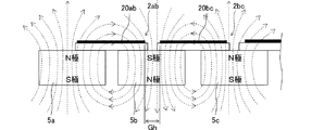
ここで、特許文献1に開示されている長尺型磁気センサの構造例を図1に示す。図1の例では、磁石5a−5bを橋渡しするように、感磁部20abを備えた磁気抵抗素子2abが配置され、磁石5b−5cを橋渡しするように、感磁部20bcを備えた磁気抵抗素子2bcが配置されている。そして互いに隣接する磁石の磁極が互いに逆方向となるように磁石5a,5b,5cが配置されている。
Here, FIG. 1 shows an example of the structure of the long magnetic sensor disclosed in
このような構造によれば、互いに隣接する2つの磁気抵抗素子の感磁部間の間隙部分Ghに磁石の中央部が位置することになる。磁石の中央部は端部付近に比べて磁束密度が高く安定しているので、隣接する感磁部間の磁束密度が、他の領域に比べて高まることになる。これにより、間隙部分Ghの検出レベルの低下を補償することができ、長手方向の全体にフラットな検出レベル特性が得られるとしている。 According to such a structure, the central portion of the magnet is positioned in the gap portion Gh between the magnetic sensitive portions of two adjacent magnetoresistive elements. Since the central portion of the magnet has a higher magnetic flux density and is stable compared to the vicinity of the end portion, the magnetic flux density between adjacent magnetic sensitive portions is higher than that of other regions. Accordingly, it is possible to compensate for a decrease in the detection level of the gap portion Gh and to obtain a flat detection level characteristic in the entire longitudinal direction.
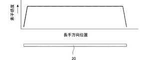
ここで、一般的な磁気抵抗素子の素子感度特性の例を図2に示す。図2において横軸は磁気抵抗素子の長手方向位置、縦軸は磁気抵抗素子の素子感度である。ここでの素子感度(K)は、磁気抵抗素子に磁界を加えたときの素子抵抗値が磁気抵抗素子に磁界を加えなかったときの磁気抵抗値の何倍になるのかを示しており、K=RB/R0(RB:磁気抵抗素子に磁界を加えているときの磁気抵抗素子の素子抵抗値、R0:磁気抵抗素子に磁界を加えていないときの磁気抵抗素子の素子抵抗値)で示される。また、この横軸に合わせて感磁部20を表している。このように、感磁部20は検出幅方向(被検知物の移動方向に対して直交する長手方向)に均等な感度を有している。
Here, an example of element sensitivity characteristics of a general magnetoresistive element is shown in FIG. In FIG. 2, the horizontal axis represents the longitudinal position of the magnetoresistive element, and the vertical axis represents the element sensitivity of the magnetoresistive element. The element sensitivity (K) here indicates how many times the element resistance value when a magnetic field is applied to the magnetoresistive element is larger than the magnetic resistance value when no magnetic field is applied to the magnetoresistive element. = RB / R0 (RB: element resistance value of magnetoresistive element when magnetic field is applied to magnetoresistive element, R0: element resistance value of magnetoresistive element when magnetic field is not applied to magnetoresistive element) . In addition, the magnetic
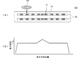
しかし特許文献1のように、磁気抵抗素子が複数の磁石に対して橋渡しする位置関係に配置されている場合であっても、例えば隣接する磁石同士の間隙が所定値よりも大きくなると、感磁部の中央部分に加わる磁束密度は、両端部に加わる磁束密度よりも若干低くなる。このため、隣接する磁石同士の間隙となる位置、例えば、磁気抵抗素子の中央部分で磁気センサの出力感度が落ち込む可能性がある。図3はこのことを表している。図3(A)は長尺型磁気センサの出力感度を示す図、図3(B)は長尺型磁気センサの磁気抵抗素子の感磁部20ab,20bcと磁石5a,5b,5cとの位置関係を示す図である。図3において、隣接する磁石同士の間隙となる位置で、すなわち感磁部20ab,20bcの中央部分で出力感度(センサが媒体を検出した時の出力電圧)の低下Dmが現れる。
However, even if the magnetoresistive element is arranged in a positional relationship that bridges a plurality of magnets as in
また、磁石の配置とは直接関係なく、磁気抵抗素子の感磁部20abと、それに隣接する磁気抵抗素子の感磁部20bcとの間には間隙が生じる。この間隙位置に感度低下Dsが現れる。 In addition, there is a gap between the magnetosensitive element 20ab of the magnetoresistive element and the magnetosensitive part 20bc of the magnetoresistive element adjacent to the magnetoresistive element, regardless of the arrangement of the magnets. A sensitivity drop Ds appears at this gap position.
本発明は、隣接する磁石同士の間隙部または隣接する磁気抵抗素子の感磁部同士の間隙部付近に生じる感度低下をより小さくできる長尺型磁気センサを提供することを目的としている。 SUMMARY OF THE INVENTION An object of the present invention is to provide a long magnetic sensor that can further reduce the sensitivity reduction that occurs in the vicinity of a gap between adjacent magnets or in the vicinity of a gap between magnetic sensing parts of adjacent magnetoresistive elements.
本発明の長尺型磁気センサは、被検知物の移動方向に対して直交する方向を長手方向とする感磁部を表面に形成した複数の磁気抵抗素子と、該磁気抵抗素子の感磁部に対して磁界を印加する複数の磁石とを有し、
前記複数の磁気抵抗素子の感磁部および前記複数の磁石は、被検知物の移動方向に対して直交する直線に沿ってそれぞれ配列され、
前記磁気抵抗素子は、前記感磁部における磁気抵抗部の密度が、隣接する前記磁石同士の間隙部上または隣接する前記磁気抵抗素子の間隙部付近で相対的に高い、もしくは隣接する前記磁石同士の間隙部上および隣接する前記磁気抵抗素子の間隙部付近で相対的に高いことを特徴としている。なおここでいう「磁気抵抗部の密度」とは、単位面積あたりに占める磁気抵抗部の面積の割合をいう。
The long magnetic sensor according to the present invention includes a plurality of magnetoresistive elements having a magnetic sensing portion formed on the surface thereof, the longitudinal direction being a direction orthogonal to the moving direction of the object to be detected, and the magnetosensitive portion of the magnetoresistive element. A plurality of magnets for applying a magnetic field to
The magnetic sensing parts of the plurality of magnetoresistive elements and the plurality of magnets are respectively arranged along a straight line perpendicular to the moving direction of the object to be detected,
In the magnetoresistive element, the density of the magnetoresistive portion in the magnetosensitive portion is relatively high on the gap portion between the adjacent magnets or in the vicinity of the gap portion between the adjacent magnetoresistive elements, or between the adjacent magnets. It is characterized in that it is relatively high on the gap portion and in the vicinity of the gap portion of the adjacent magnetoresistive element. The “density of the magnetoresistive portion” here refers to the ratio of the area of the magnetoresistive portion occupying per unit area.
例えば、前記磁気抵抗素子は、前記複数の磁石のうち隣接する磁石同士を橋渡しする位置関係で配置される。 For example, the magnetoresistive elements are arranged in a positional relationship that bridges adjacent magnets among the plurality of magnets.
また、例えば前記磁気抵抗素子は、長手方向の両端部(すなわち隣接する磁気抵抗素子の感磁部同士の間隙部の付近)での前記感磁部における前記磁気抵抗部の密度が相対的に高い。 In addition, for example, the magnetoresistive element has a relatively high density of the magnetoresistive portion in the magnetosensitive portion at both ends in the longitudinal direction (that is, in the vicinity of the gap between the magnetosensitive portions of adjacent magnetoresistive elements). .
前記複数の磁石は、前記複数の磁気抵抗素子の感磁部に対する磁極の向きが、隣接する磁石同士で互いに逆となるように配置されてもよい。または、前記複数の磁気抵抗素子の感磁部に対する磁極の向きが同一となるように配置されてもよい。 The plurality of magnets may be arranged such that directions of magnetic poles with respect to the magnetic sensing portions of the plurality of magnetoresistive elements are opposite to each other between adjacent magnets. Alternatively, the plurality of magnetoresistive elements may be arranged so that the magnetic poles have the same direction with respect to the magnetic sensitive portions.
本発明によれば、磁気抵抗素子は、感磁部の磁気抵抗部のうち、隣接する磁石同士の間隙部上の密度または隣接する磁気抵抗素子の間隙部付近における密度がその他の領域の密度に比べて相対的に高く形成されることにより、隣接する磁石同士の間隙部に生じる感度低下または隣接する磁気抵抗素子の間隙部(より具体的には、感磁部同士の間隙部)付近に生じる感度低下をより小さくできる。 According to the present invention, in the magnetoresistive element, the density on the gap between adjacent magnets in the magnetoresistive part of the magnetosensitive part or the density in the vicinity of the gap between adjacent magnetoresistive elements is equal to the density of other regions. By being formed relatively high, sensitivity is lowered in the gap between adjacent magnets or in the vicinity of the gap between adjacent magnetoresistive elements (more specifically, the gap between the magnetic sensitive parts). Sensitivity degradation can be further reduced.
《第1の実施形態》
第1の実施形態に係る長尺型磁気センサの構成を図4〜図7を参照して説明する。
<< First Embodiment >>
The configuration of the long magnetic sensor according to the first embodiment will be described with reference to FIGS.
図4は第1の実施形態の長尺型磁気センサの外観斜視図であり、(A)はカバーの取り付け途中の状態、(B)は取り付け状態を示している。樹脂製のケース1にはその上部に磁気抵抗素子を収納するための凹部が複数形成されており、該凹部に磁気抵抗素子2a,2b,2c,2d・・・が収納されている。また、ケース1の下部には、複数の磁石を収納するための磁石収納凹部(図示せず)がケース長手方向に直線に沿って並んで形成されており、該磁石収納凹部にそれぞれの磁石が収納されている。これらの複数の磁石は厳密に直線に沿って配列されていなくてもよく、多少のずれがあってもよい。例えば、ケース短手方向に多少ずらして千鳥状に配置されていてもよい。
4A and 4B are external perspective views of the long magnetic sensor of the first embodiment. FIG. 4A shows a state in the middle of attachment of the cover, and FIG. 4B shows an attachment state. The
ケース1の下部には、複数の磁気抵抗素子2a,2b,2c,2d・・・に電気的に接続された端子ピン6が引き出されている。ケース1の両側部には長手方向に沿って爪部係合溝3が設けられている。
A
金属製のカバー4には、ケースの爪部係合溝3に係合するカバー固定爪部が設けられていて、両者の係合状態で長手方向にスライドさせることによって、図4(B)に示すようにケース1の上部をカバー4が覆う。被検知物100は図中矢印で示すように長尺型磁気センサ301の長手方向に直交する向きに搬送される。この長尺型磁気センサ301の長手方向に対する被検知物100の搬送方向は、厳密に90度ではなくて多少の角度のずれがあってもよい。
The
なお、カバー4には回路基板に対して電気的にアース接続するためのカバー端子11が設けられている。
The
図5(A)は、図4に示した第1の実施形態の長尺型磁気センサのカバーを取り除いた状態での平面図である。図5(B)は感磁部形成面に垂直で且つ複数の磁気抵抗素子と複数の磁石部分を通る面での模式断面図である。但し、ここでは磁気抵抗素子2a〜2d部分についてのみ示している。また、図5(B)ではケース1および端子ピン6についても図示を省略している。
FIG. 5A is a plan view of the long magnetic sensor according to the first embodiment shown in FIG. 4 with the cover removed. FIG. 5B is a schematic cross-sectional view taken along a plane that is perpendicular to the magnetic sensing portion forming surface and passes through the plurality of magnetoresistive elements and the plurality of magnet portions. However, only the
磁気抵抗素子2a〜2dの下部には磁石5a〜5dが配置されている。磁気抵抗素子2a〜2dにはそれぞれ感磁部20a〜20dが形成されている。図4に示した被検知物100が紙幣等の紙葉類である場合、それが長尺型磁気センサ301の長手方向に対して直交する向きに搬送される。感磁部20a〜20dは、被検知物の移動方向に対して直交する方向を長手方向として磁気抵抗素子2a〜2dの表面に形成されている。
各磁石5a〜5dは磁気抵抗素子2a〜2dのそれぞれを磁束が垂直に貫くように磁極(N極とS極)の方向が定められていて、且つ隣接する磁石の磁極の方向が互いに逆方向となるように配置されている。すなわち、磁石5aは磁気抵抗素子2a側がN極、それに隣接する磁石5bは磁気抵抗素子2b側がS極である。さらにそれに隣接する磁石5cは磁気抵抗素子2c側がN極である。以降同様に隣接する磁石の磁極の方向が互いに逆方向となるように配置されている。
Each
図6(A)は図5に示した第1の実施形態の磁気抵抗素子2a〜2d等のうち一つの磁気抵抗素子の平面図、図6(B)は磁気抵抗素子の素子感度特性を示す図である。
6A is a plan view of one of the
磁気抵抗素子201の感磁部20は、磁気抵抗層の上面に複数の電極材料からなるショートバー22が形成されたものである。磁気抵抗部21はショートバー22で覆われていない部分である。ショートバー22が存在する箇所はショートバー22に電流が流れ、ショートバー22が存在しない箇所は磁気抵抗部21に電流が流れる。
The
紙幣に印刷された磁性体(磁性インク)101が図6(A)に示す矢印方向に通過する際、その通過位置によって磁気抵抗素子201の抵抗値の変化率(素子感度)が異なる。この磁気抵抗素子201の抵抗値の変化率は、磁気抵抗部21の密度が高いほど大きい。図6(A)に示した例では、感磁部20の長手方向中央部分の磁気抵抗部21の密度が、その他の領域の密度に比べて高いので、図6(B)に示すように、感磁部20の中央部分の感度が高くなる。
When the magnetic body (magnetic ink) 101 printed on the banknote passes in the arrow direction shown in FIG. 6A, the rate of change (element sensitivity) of the resistance value of the
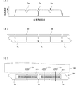
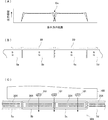
図7(A)は第1の実施形態の長尺型磁気センサの出力感度特性を示す図、図7(B)は長尺型磁気センサの磁気抵抗素子201の感磁部20と磁石5a,5b,5cとの位置関係を示す模式図である。図7(C)は長尺型磁気センサ301の主要部の部分平面図であり、紙幣などの被検知物100に印刷されている磁性体101の通過位置の例を示している。図7(A)において、破線は従来構造の長尺型磁気センサの特性(図3(A)に示した特性)、実線は第1の実施形態に係る長尺型磁気センサの特性である。磁気抵抗素子の感磁部20の中央(隣接する磁石同士5a,5bの間隙および磁石5b,5cの間隙となる位置)での磁気センサ301の感度低下Dmは従来構造のものに比べて小さい。
FIG. 7A is a diagram showing the output sensitivity characteristics of the long magnetic sensor of the first embodiment, and FIG. 7B is a magnetic
第1の実施形態によれば、隣接する磁石5a,5bの間隙および磁石5b,5cの間隙となる領域上に位置する磁気抵抗素子201の磁気抵抗部21の密度を、その他の領域と比べて相対的に高くすることによって、磁気抵抗部21の密度が高い領域の磁気抵抗素子201の感度が上昇するため、磁石5a,5bおよび5b,5cの間隙部に生じる磁気センサとしての感度低下Dmを緩和できる。
According to 1st Embodiment, the density of the
なお、図7(A)に示した感度低下Dsは感磁部同士を近づけることによって、その度合いを比較的容易に抑制できるが、感度低下Dmは抑制しにくい。その理由を具体的に説明すると、磁石5a,5b,5cと、これらの磁石を収納する樹脂製のケース1(図4参照)とは一般的に線膨張係数が大きく異なるため、製造条件・外的環境によってはケースが伸縮する。このケースの伸縮を吸収するために隣接する磁石同士にある程度の間隙を設けざるを得ず、その結果、感度低下Dmが生じる、という事情がある。第1の実施形態で示したように、隣接する磁石同士の間隙部上の領域に位置する磁気抵抗部の密度を高めることによって、前記感度低下Dmを効果的に低減できる。
Note that the sensitivity decrease Ds shown in FIG. 7A can be suppressed relatively easily by bringing the magnetic sensing portions closer to each other, but the sensitivity decrease Dm is difficult to suppress. Specifically, the
《第2の実施形態》
第2の実施形態では、複数の磁気抵抗素子の感磁部20のパターンが第1の実施形態と異なる例について示す。
<< Second Embodiment >>
In the second embodiment, an example in which the pattern of the
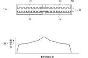
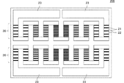
図8(A)は第2の実施形態に係る磁気抵抗素子202の平面図、図8(B)はその磁気抵抗素子202の素子感度特性を示す図である。磁気抵抗素子202は二列の感磁部20を備えている。感磁部の両端は引出電極23に接続されている。
FIG. 8A is a plan view of the
図9(A)は第2の実施形態の感磁部20の部分拡大斜視図、図9(B)は図9(A)におけるA−A部分の断面図である。磁気抵抗層21Lはミアンダライン状に形成されていて、その表面に電極材料からなるショートバー(電極)22が形成されている。ショートバー22が存在しない箇所は磁気抵抗部21である。図9(B)に矢印で示すように、ショートバー22が存在する箇所はショートバー22に電流が流れ、ショートバー22が存在しない箇所は磁気抵抗層21Lに電流が流れる。
FIG. 9A is a partially enlarged perspective view of the
図8(A)に示すように、感磁部20の両端から中央にかけて磁気抵抗部の密度を次第に相対的に高くしている。そのため、図8(B)に示すように、感磁部20の両端から中央にかけて感度が次第に増大する感度特性が得られる。
As shown in FIG. 8A, the density of the magnetoresistive portion is gradually increased from both ends of the
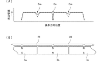
図10は第2の実施形態の長尺型磁気センサの感度特性を示す図である。図10(A)は長尺型磁気センサの出力感度特性を示す図、図10(B)は長尺型磁気センサの磁気抵抗素子の感磁部20と磁石5a,5b,5cとの位置関係を示す図である。図10(A)において、破線は従来構造の長尺型磁気センサの特性(図3(A)に示した特性)、実線は第2の実施形態に係る長尺型磁気センサの特性である。磁気抵抗素子の感磁部20の中央(隣接する磁石同士5a,5bの間隙および磁石5b,5cの間隙となる位置)での磁気センサの感度低下Dmは従来構造のものに比べて小さい。
FIG. 10 is a diagram illustrating sensitivity characteristics of the long magnetic sensor according to the second embodiment. FIG. 10A shows the output sensitivity characteristic of the long magnetic sensor, and FIG. 10B shows the positional relationship between the
第2の実施形態によれば隣接する磁石5a,5bの上に位置する磁気抵抗素子202の磁気抵抗部21の密度を、その他の領域と比べて相対的に高くすることによって、磁気抵抗部21の密度が高い領域の磁気抵抗素子202の感度が上昇するため、磁石5a,5bおよび5b,5cの間隙部に生じる磁気センサとしての出力感度低下Dmを緩和できる。
According to the second embodiment, the
《第3の実施形態》
第3の実施形態では、複数の磁石の極性が第1・第2の実施形態と異なる例について示す。
<< Third Embodiment >>
In the third embodiment, an example in which the polarities of a plurality of magnets are different from those in the first and second embodiments will be described.
図11は、複数の磁石5a〜5d等の極性と感磁部20を通過する磁束の概念図である。図11(A)の例では、複数の磁石5a〜5d等のうち隣接する磁石の極性が逆極性である。この配置を以下、「逆極性配置」という。図11(B)の例では、すべての磁石5a〜5d等について極性が一致している。この配置を以下、「同極性配置」という。
FIG. 11 is a conceptual diagram of the polarities of the plurality of
図11(A)のように、複数の磁石5a〜5d等のうち隣接する磁石の極性が異なる配置であると、磁石による磁束は隣接する磁石間でループを描く。このため磁気抵抗素子の感磁部20を通る磁束は、感磁部の両端部分(磁石中央部)では感磁部20に対してほぼ垂直であるが、感磁部20の中央部分(磁石同士の間隙部)は殆ど水平成分となる。
As shown in FIG. 11A, when the magnets adjacent to each other among the plurality of
磁気抵抗素子の抵抗値は磁気抵抗素子の感磁部20に垂直に通過する磁束によって変化するので、感磁部20の中央部の感度は低下することになる。
Since the resistance value of the magnetoresistive element changes depending on the magnetic flux passing perpendicularly to the
一方、図11(B)のように、すべての磁石5a〜5d等の極性が一致していると、磁束は磁気抵抗素子の感磁部20に対して垂直に通り、磁束密度はほぼ均等である。磁石同士の間隙部では磁束密度が少し低いので、感磁部20の中央部の感度は若干低下するだけである。
On the other hand, as shown in FIG. 11B, when the polarities of all the
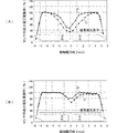
図12は、図8に示した磁気抵抗素子(第2の実施形態で示したもの)と従来構造の磁気抵抗素子(検知幅の全体にわたって磁気抵抗部の密度が均一なもの)を用いた場合について、磁石の二つの配置構造での磁気センサの出力電圧変動率を示す図である。図12(A)は磁石を逆極性配置した場合の特性、図12(B)は磁石を同極性配置した場合の特性である。いずれも、二つの磁石と一つの磁気抵抗素子との組み合わせについて示している。図12(A)、図12(B)において、特性Pは本実施形態の磁気センサの出力電圧変動率、特性Cは従来構造の磁気抵抗素子を備えた磁気センサの出力電圧変動率をそれぞれ表している。 FIG. 12 shows a case where the magnetoresistive element shown in FIG. 8 (shown in the second embodiment) and a conventional magnetoresistive element (thickness of the magnetoresistive portion is uniform over the entire detection width) are used. It is a figure which shows the output voltage fluctuation rate of the magnetic sensor in two arrangement structure of a magnet. FIG. 12A shows characteristics when magnets are arranged in reverse polarity, and FIG. 12B shows characteristics when magnets are arranged with the same polarity. In either case, a combination of two magnets and one magnetoresistive element is shown. 12A and 12B, the characteristic P represents the output voltage fluctuation rate of the magnetic sensor of the present embodiment, and the characteristic C represents the output voltage fluctuation rate of the magnetic sensor provided with the conventional magnetoresistive element. ing.
図12(A)、図12(B)において、縦軸のセンサ出力電圧変動率は、磁気センサを接続した検出回路の出力電圧の変動率で測定したものである。具体的には、例えば磁気抵抗素子に含まれる二つの感磁部を抵抗ブリッジ回路に接続し、被検知対象である磁性体の通過前後での前記抵抗ブリッジ回路の出力電圧の変動率に相当する。この変動率は出力電圧の最大値に対する比率をパーセントで表している。実線は図8に示した磁気抵抗素子の特性、破線は従来構造の磁気抵抗素子の特性である。いずれも、磁気抵抗素子の感磁部の長さは10mm、磁石同士の間隙部の間隔は0.7mm、磁気抵抗部の密度が高い領域における隣接する
磁気抵抗部間の最小距離は0.17mm、その他の領域における隣接する磁気抵抗部間の距離は0.35mmである。
In FIGS. 12A and 12B, the sensor output voltage fluctuation rate on the vertical axis is measured by the fluctuation rate of the output voltage of the detection circuit connected to the magnetic sensor. Specifically, for example, two magnetosensitive parts included in the magnetoresistive element are connected to a resistance bridge circuit, which corresponds to the variation rate of the output voltage of the resistance bridge circuit before and after passing through the magnetic material to be detected. . This variation rate represents the ratio of the output voltage to the maximum value as a percentage. A solid line indicates the characteristics of the magnetoresistive element shown in FIG. 8, and a broken line indicates the characteristics of the magnetoresistive element having the conventional structure. In both cases, the length of the magnetosensitive element of the magnetoresistive element is 10 mm, the gap between the magnets is 0.7 mm, and the minimum distance between adjacent magnetoresistive parts in the high density region is 0.17 mm. The distance between adjacent magnetoresistive portions in other regions is 0.35 mm.
逆極性配置の場合、感磁部の両端から中央にかけて広範囲に亘って感度が低下していて、中央部での大きく感度が低下している。これに対し、同極性配置の場合、感磁部の中央部の比較的狭い範囲で感度が低下している。また、感度の低下量も全体に少ない。この感度低下の度合いは隣接する磁石同士の間隙によっても変わる。さらには、検出対象(磁性インク等)の大きさ(感磁部を通過する幅など)によっても変わる。 In the case of the reverse polarity arrangement, the sensitivity is reduced over a wide range from both ends of the magnetic sensitive portion to the center, and the sensitivity is greatly reduced at the central portion. On the other hand, in the case of the same polarity arrangement, the sensitivity is lowered in a relatively narrow range at the center of the magnetic sensitive part. In addition, the amount of decrease in sensitivity is small overall. The degree of this sensitivity reduction also varies depending on the gap between adjacent magnets. Furthermore, it varies depending on the size of the detection target (magnetic ink or the like) (the width passing through the magnetic sensitive part).
このような感度低下の度合いは磁石の極性、磁石同士の間隙、検出対象の大きさに応じて異なるが、その感度低下のパターンに応じてその感度低下を抑制するように、磁気抵抗素子の磁気抵抗部の密度を定めればよい。具体的には、隣接する磁石同士の間隙部の影響を極力小さくして、よりフラットな出力特性を得たい場合には磁石を同極性配置にすることが好ましい。一方、フラットな出力特性を多少犠牲にしたとしても、隣接する磁石同士の配置しやすさ等を求める場合には磁石を異極性配置にすることが好ましい。 The degree of such sensitivity reduction varies depending on the polarity of the magnet, the gap between the magnets, and the size of the detection target, but the magnetic resistance of the magnetoresistive element is controlled so as to suppress the sensitivity degradation depending on the sensitivity reduction pattern. What is necessary is just to determine the density of a resistance part. Specifically, when it is desired to minimize the influence of the gap between adjacent magnets and to obtain a flatter output characteristic, the magnets are preferably arranged in the same polarity. On the other hand, even if the flat output characteristics are sacrificed to some extent, it is preferable to arrange the magnets in different polarities in order to determine the ease of arranging adjacent magnets.
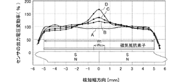
ここでは、磁気抵抗素子の感磁部の中央部の磁気抵抗部の密度の比率を変化させたときの磁気抵抗素子の感度特性の変化を示す。図13は、磁気抵抗素子の感磁部の中央部の磁気抵抗部の密度の比率を変化させたときの磁気センサの出力電圧変動率の変化について示す図である。図13において、横軸は磁気センサの長手方向(検知幅方向)の位置であり、横軸の0は所定の磁気抵抗素子の中央(隣接する磁石同士の間隙部の中央となる位置)である。なお、ここでは磁石間に間隙を設けずに、磁気抵抗部の密度の違いによる差を確認した。図13の縦軸のセンサ出力電圧変動率は、磁気センサを接続した検出回路の出力電圧の変動率である。具体的には、例えば磁気抵抗素子に含まれる二つの感磁部を抵抗ブリッジ回路に接続し、被検知対象である磁性体の通過前後での前記抵抗ブリッジ回路の出力電圧の変動率に相当する。 Here, the change in the sensitivity characteristic of the magnetoresistive element when the density ratio of the magnetoresistive part at the center of the magnetosensitive part of the magnetoresistive element is changed is shown. FIG. 13 is a diagram illustrating a change in the output voltage fluctuation rate of the magnetic sensor when the density ratio of the magnetoresistive portion at the center of the magnetosensitive portion of the magnetoresistive element is changed. In FIG. 13, the horizontal axis is the position in the longitudinal direction (detection width direction) of the magnetic sensor, and 0 on the horizontal axis is the center of a predetermined magnetoresistive element (position that is the center of the gap between adjacent magnets). . In addition, the difference by the difference in the density of a magnetoresistive part was confirmed without providing a gap | interval between magnets here. The sensor output voltage fluctuation rate on the vertical axis in FIG. 13 is the fluctuation rate of the output voltage of the detection circuit connected to the magnetic sensor. Specifically, for example, two magnetosensitive parts included in the magnetoresistive element are connected to a resistance bridge circuit, which corresponds to the variation rate of the output voltage of the resistance bridge circuit before and after passing through the magnetic material to be detected. .
図13に示した磁気抵抗素子の感度特性A〜Dと磁気抵抗素子の感磁部の中央部の磁気抵抗部の密度の比率との関係と測定条件は次のとおりである。なお、磁気センサとしては、図8に示される磁気抵抗素子を用い、磁石は同極性配置とした。また、磁気抵抗部の密度は、磁気抵抗素子の中央部幅Wcに位置するミアンダライン状のパターンの数を他の領域に比べて増やすことによって変化させた。 The relationship between the sensitivity characteristics A to D of the magnetoresistive element shown in FIG. 13 and the ratio of the density of the magnetoresistive part at the center of the magnetosensitive part of the magnetoresistive element and the measurement conditions are as follows. In addition, as a magnetic sensor, the magnetoresistive element shown in FIG. 8 was used, and the magnets were arranged with the same polarity. Further, the density of the magnetoresistive portion was changed by increasing the number of meander line patterns located in the central portion width Wc of the magnetoresistive element as compared with other regions.
検出対象:幅1mmの磁性インク
磁気抵抗素子の検出幅Wt:10mm
磁気抵抗素子の中央部幅Wc:1mm
検出幅Wtに対する中央部幅Wcの磁気抵抗部の存在割合
特性A:10%
特性B:13%
特性C:15%
特性D:20%
図13から明らかなように、この例では、磁石を同極性配置し、且つ磁石間の間隙を無くしているので、感度特性Aのように感磁部の中央での感度低下はもともと小さいが、磁気抵抗素子の感磁部の中央部の磁気抵抗部の密度の比率を高めるほど、感磁部の中央部での感度増大効果が高まることがわかる。
Detection target: magnetic ink having a width of 1 mm Detection width Wt of the magnetoresistive element: 10 mm
The center width Wc of the magnetoresistive element: 1 mm
Presence ratio of magnetoresistive portion with center width Wc with respect to detection width Wt Characteristic A: 10%
Characteristic B: 13%
Characteristic C: 15%
Property D: 20%
As is apparent from FIG. 13, in this example, the magnets are arranged with the same polarity and the gap between the magnets is eliminated, so that the sensitivity reduction at the center of the magnetic sensing part is originally small as in the sensitivity characteristic A, It can be seen that as the density ratio of the magnetoresistive portion at the center of the magnetosensitive portion of the magnetoresistive element is increased, the sensitivity increasing effect at the central portion of the magnetosensitive portion is enhanced.
《第4の実施形態》
図14(A)は第4の実施形態に係る磁気抵抗素子204の平面図、図14(B)はその磁気抵抗素子204の素子感度特性を示す図である。磁気抵抗素子204は二列の感磁部20を備えている。感磁部の両端は引出電極23に接続されている。
<< Fourth Embodiment >>
FIG. 14A is a plan view of a
第4の実施形態では、図14(A)に示すように、感磁部20の長手方向中央から両端にかけて磁気抵抗部の密度を次第に高くしている。すなわち隣接する磁気抵抗素子の感磁部同士の間隙部の付近に位置する磁気抵抗部の密度を高くしている。そのため、図14(B)に表れているように、感磁部20の中央部分から両端部分にかけて素子感度が次第に高くなる素子感度特性が得られる。そのため、隣接する磁気抵抗素子の間隙部付近での出力感度低下Ds(図7(A)参照。)を緩和できる。なお、「隣接する磁気抵抗素子の間隙部付近」とは、隣接する磁気抵抗素子の間隙部の周辺領域を意図しており、実質的には磁気抵抗素子の端部分の領域を示すものである。
In the fourth embodiment, as shown in FIG. 14A, the density of the magnetoresistive portion is gradually increased from the center in the longitudinal direction of the magnetic
図15(A)は長尺型磁気センサの出力感度特性を示す図、図15(B)は長尺型磁気センサの磁気抵抗素子の感磁部20と磁石5b,5cとの位置関係を示す図である。図15(C)は長尺型磁気センサ304の主要部の部分平面図であり、紙幣などの被検知物100に印刷されている磁性体101の通過位置の例を示している。図15(A)において、破線は従来構造の長尺型磁気センサの特性、実線は第5の実施形態に係る長尺型磁気センサの特性である。磁気抵抗素子の感磁部20の両端、且つ隣接する磁石同士の間隙部となる位置、での感度低下Dsは従来構造のものに比べて小さい。
FIG. 15A shows the output sensitivity characteristics of the long magnetic sensor, and FIG. 15B shows the positional relationship between the
第4の実施形態によれば、磁気抵抗素子204を配列した状態で、隣接する磁気抵抗素子204の感磁部20同士の間隙部の付近に位置する磁気抵抗部の密度が高くなることによって、磁気抵抗部の密度が高い領域のセンサ出力感度が上昇する。そのため、隣接する感磁部20同士の間隙部となる位置での磁気センサ304としての出力感度低下Dsを緩和できる。
According to the fourth embodiment, in a state where the
《第5の実施形態》
図16(A)は第5の実施形態に係る磁気抵抗素子205の平面図、図16(B)はその磁気抵抗素子205の素子感度特性を示す図である。磁気抵抗素子205は二列の感磁部20を備えている。感磁部の両端は引出電極23に接続されている。
<< Fifth Embodiment >>
FIG. 16A is a plan view of a
第5の実施形態では、図16(A)に示すように、感磁部20の長手方向中央部分の磁気抵抗部21の密度をその他の領域の密度に比べて高くした上、感磁部20の中央から両端にかけて磁気抵抗部の密度を次第に高くしている。すなわち、隣接する磁石の上に位置する磁気抵抗素子205の磁気抵抗部21の密度を、その他の領域と比べて相対的に高くしつつ、隣接する磁気抵抗素子205の感磁部同士の間隙部の付近に位置する磁気抵抗部の密度を高くしている。そのため、図16(B)に表れているように、感磁部20の中央部分、及び中央部分から両端部分にかけて素子感度が次第に高くなる素子感度特性が得られる。そのため、磁気センサ同士の隣接位置での出力感度低下Ds(図7(A)参照。)および隣接する磁石同士の間隙部での磁気センサとしての出力感度低下Dm(図7(A)参照。)を緩和できる。
In the fifth embodiment, as shown in FIG. 16A, the density of the
《第6の実施形態》
第6の実施形態では、磁気抵抗素子の感磁部のうちの磁気抵抗部の密度を長手方向の位置で異ならせるための別の構造(第1〜第5の実施形態で示したものとは異なる構造)を示す。
<< Sixth Embodiment >>
In the sixth embodiment, another structure for differentiating the density of the magnetoresistive portion of the magnetosensitive portion of the magnetoresistive element at the position in the longitudinal direction (the one shown in the first to fifth embodiments) Different structure).
図17は、第6の実施形態の磁気抵抗素子206の感磁部形成面の磁気抵抗部および電極のパターンをそれぞれ示す図である。磁気抵抗素子206は二列の感磁部20を備えている。感磁部20の両端は引出電極23に接続されている。
FIG. 17 is a diagram showing the pattern of the magnetoresistive portion and the electrode on the magnetosensitive portion forming surface of the
図17の例では、感磁部20は、ミアンダライン状に形成された磁気抵抗層と、この磁気抵抗層上に形成されたショートバー(電極)22とで構成されている。ショートバー22が存在しない箇所は磁気抵抗部21である。この例では、感磁部20の長手方向での中央ほど磁気抵抗部21の密度が高い。そのため、感磁部20の長手方向での中央ほど磁気センサの感度が高くなる。
In the example of FIG. 17, the
《第7の実施形態》
第7の実施形態では、磁気抵抗素子の感磁部のうちの磁気抵抗部の密度を長手方向の位置で異ならせるためのさらに別の構造を示す。
<< Seventh Embodiment >>
The seventh embodiment shows still another structure for making the density of the magnetoresistive part of the magnetosensitive part of the magnetoresistive element different at the position in the longitudinal direction.
図18は、第7の実施形態の磁気抵抗素子207の感磁部形成面の磁気抵抗部および電極のパターンをそれぞれ示す図である。磁気抵抗素子207は二列の感磁部20を備えている。感磁部20の両端は引出電極23に接続されている。
FIG. 18 is a diagram showing the pattern of the magnetoresistive part and the electrode on the magnetic sensitive part forming surface of the
図18の例では、感磁部20は、ミアンダライン状に形成された磁気抵抗層と、この磁気抵抗層上に形成されたショートバー22とで構成されている。この例では、感磁部20の長手方向での中央ほど磁気抵抗層の線幅が太い。そのため、感磁部20の長手方向での中央ほど磁気センサの出力感度が高くなる。
In the example of FIG. 18, the
《第8の実施形態》
第8の実施形態では、磁気抵抗素子の感磁部のうちの磁気抵抗部の密度を長手方向の位置で異ならせるためのさらに別の構造を示す。
<< Eighth Embodiment >>
In the eighth embodiment, still another structure for varying the density of the magnetoresistive portion of the magnetosensitive portion of the magnetoresistive element at the position in the longitudinal direction is shown.
図19は、第8の実施形態の磁気抵抗素子208の感磁部形成面の磁気抵抗部および電極のパターンをそれぞれ示す図である。磁気抵抗素子208は二列の感磁部20を備えている。感磁部20の両端は引出電極23に接続されている。
FIG. 19 is a diagram showing the pattern of the magnetoresistive portion and the electrode on the magnetosensitive portion forming surface of the
図19の例では、感磁部20は、直線状に形成された磁気抵抗層と、この磁気抵抗層上に形成されたショートバー22とで構成されている。この例では、感磁部20の長手方向での中央ほど磁気抵抗部の密度が高い。そのため、感磁部20の長手方向での中央ほど磁気センサの出力感度が高くなる。
In the example of FIG. 19, the magnetic
《第9の実施形態》
第9の実施形態では、磁気抵抗素子の感磁部のうちの磁気抵抗部の密度を長手方向の位置で異ならせるためのさらに別の構造を示す。
<< Ninth embodiment >>
In the ninth embodiment, still another structure for varying the density of the magnetoresistive portion of the magnetosensitive portion of the magnetoresistive element at the position in the longitudinal direction is shown.
図20は、第9の実施形態の磁気抵抗素子209の感磁部形成面の磁気抵抗部および電極のパターンをそれぞれ示す図である。磁気抵抗素子209は二列の感磁部20を備えている。感磁部20の両端は引出電極23に接続されている。
FIG. 20 is a diagram showing the pattern of the magnetoresistive part and the electrode on the magnetic sensitive part forming surface of the
図20の例では、感磁部20は、線状に形成された磁気抵抗層と、この磁気抵抗層上に形成されたショートバー22とで構成されている。この例では、感磁部20の長手方向での中央ほど磁気抵抗層の線幅が太い。そのため、感磁部20の長手方向での中央ほど磁気センサの出力感度が高くなる。
In the example of FIG. 20, the magnetic
1…ケース
3…爪部係合溝
4…カバー
5a,5b,5c…磁石
6…端子ピン
11…カバー端子
20…感磁部
20a…感磁部
20ab…感磁部
20bc…感磁部
21…磁気抵抗部
21L…磁気抵抗層
22…ショートバー
23…引出電極
100…被検知物
101…磁性体
201,202,204〜209…磁気抵抗素子
301,304…長尺型磁気センサ
DESCRIPTION OF
Claims (5)
前記複数の磁気抵抗素子の感磁部および前記複数の磁石は、被検知物の移動方向に対して直交する直線に沿ってそれぞれ配列され、
前記磁気抵抗素子は、前記感磁部における磁気抵抗部の密度が、隣接する前記磁石同士の間隙部上または隣接する前記磁気抵抗素子の間隙部付近で相対的に高い、もしくは隣接する前記磁石同士の間隙部上および隣接する前記磁気抵抗素子の間隙部付近で相対的に高いことを特徴とする長尺型磁気センサ。 A plurality of magnetoresistive elements formed on the surface with a magnetosensitive part whose longitudinal direction is perpendicular to the moving direction of the object to be detected, and a plurality of magnets that apply a magnetic field to the magnetosensitive part of the magnetoresistive element And
The magnetic sensing parts of the plurality of magnetoresistive elements and the plurality of magnets are respectively arranged along a straight line perpendicular to the moving direction of the object to be detected,
In the magnetoresistive element, the density of the magnetoresistive portion in the magnetosensitive portion is relatively high on the gap portion between the adjacent magnets or in the vicinity of the gap portion between the adjacent magnetoresistive elements, or between the adjacent magnets. A long magnetic sensor characterized in that it is relatively high above and near the gap between adjacent magnetoresistive elements.
Priority Applications (2)
| Application Number | Priority Date | Filing Date | Title |
|---|---|---|---|
| JP2011176464A JP5494591B2 (en) | 2010-09-28 | 2011-08-12 | Long magnetic sensor |
| CN201110271871.3A CN102435961B (en) | 2010-09-28 | 2011-09-14 | Long-type magnetic sensor |
Applications Claiming Priority (3)
| Application Number | Priority Date | Filing Date | Title |
|---|---|---|---|
| JP2010217250 | 2010-09-28 | ||
| JP2010217250 | 2010-09-28 | ||
| JP2011176464A JP5494591B2 (en) | 2010-09-28 | 2011-08-12 | Long magnetic sensor |
Publications (2)
| Publication Number | Publication Date |
|---|---|
| JP2012093342A JP2012093342A (en) | 2012-05-17 |
| JP5494591B2 true JP5494591B2 (en) | 2014-05-14 |
Family
ID=46386807
Family Applications (1)
| Application Number | Title | Priority Date | Filing Date |
|---|---|---|---|
| JP2011176464A Expired - Fee Related JP5494591B2 (en) | 2010-09-28 | 2011-08-12 | Long magnetic sensor |
Country Status (1)
| Country | Link |
|---|---|
| JP (1) | JP5494591B2 (en) |
Families Citing this family (8)
| Publication number | Priority date | Publication date | Assignee | Title |
|---|---|---|---|---|
| JP2014115232A (en) * | 2012-12-11 | 2014-06-26 | Dmt:Kk | Magnetic detection probe and method of manufacturing the same |
| JP6359858B2 (en) * | 2014-04-04 | 2018-07-18 | キヤノン電子株式会社 | Magnetic field detection device and magnetic identification device |
| JP2016095138A (en) * | 2014-11-12 | 2016-05-26 | Tdk株式会社 | Magnetic sensor |
| JP6475015B2 (en) * | 2014-12-26 | 2019-02-27 | セイコーNpc株式会社 | Magnetic line sensor |
| US10890630B2 (en) | 2016-05-24 | 2021-01-12 | Tdk Corporation | Magnetic sensor |
| WO2018116783A1 (en) * | 2016-12-21 | 2018-06-28 | 株式会社村田製作所 | Magnetic sensor |
| JP2019211405A (en) * | 2018-06-07 | 2019-12-12 | Tdk株式会社 | Magnetic sensor connection body |
| JP2023097943A (en) * | 2021-12-28 | 2023-07-10 | グローリー株式会社 | Magnetic feature detection device, and paper sheet identification device |
Family Cites Families (8)
| Publication number | Priority date | Publication date | Assignee | Title |
|---|---|---|---|---|
| JP2848081B2 (en) * | 1992-02-21 | 1999-01-20 | 日本鋼管株式会社 | Magnetic flaw detector |
| JPH06281625A (en) * | 1993-03-26 | 1994-10-07 | Nippon Steel Corp | Sensitivity calibration device for magnetic leakage inspection equipment |
| JP3651433B2 (en) * | 2001-09-28 | 2005-05-25 | 株式会社村田製作所 | Magnetic sensor |
| JP2003107140A (en) * | 2001-09-28 | 2003-04-09 | Nec Tokin Corp | Magnetic sensor |
| WO2005083457A1 (en) * | 2004-02-27 | 2005-09-09 | Murata Manufacturing Co., Ltd. | Prolonged magnetic sensor |
| JP2005300228A (en) * | 2004-04-07 | 2005-10-27 | Murata Mfg Co Ltd | Long-length type magnetic sensor |
| JP2008185391A (en) * | 2007-01-29 | 2008-08-14 | Matsushita Electric Ind Co Ltd | Magnetic sensor and tilt angle sensor using the same |
| JP2008209305A (en) * | 2007-02-27 | 2008-09-11 | Toshiba Corp | Magnetic flaw detector |
-
2011
- 2011-08-12 JP JP2011176464A patent/JP5494591B2/en not_active Expired - Fee Related
Also Published As
| Publication number | Publication date |
|---|---|
| JP2012093342A (en) | 2012-05-17 |
Similar Documents
| Publication | Publication Date | Title |
|---|---|---|
| JP5494591B2 (en) | Long magnetic sensor | |
| JP3879777B2 (en) | Long magnetic sensor | |
| JP4837749B2 (en) | Magnetic sensor and magnetic encoder using the same | |
| CN102435961B (en) | Long-type magnetic sensor | |
| WO2009151024A1 (en) | Magnetic sensor and magnetic sensor module | |
| JP2017072375A (en) | Magnetic sensor | |
| JP2015219227A (en) | Magnetic sensor | |
| WO2019167598A1 (en) | Magnetic sensor | |
| JP2013044641A (en) | Magnetic sensor | |
| WO2013190950A1 (en) | Magnetic sensor | |
| JP2009025047A (en) | Magnetic sensor and magnetic encoder provided with the same | |
| WO2011074488A1 (en) | Magnetic sensor | |
| WO2014156751A1 (en) | Magnetic sensor | |
| US11467231B2 (en) | Magnetic sensor | |
| CN116609712A (en) | magnetic sensor | |
| WO2015125699A1 (en) | Magnetic sensor | |
| JP2005249468A (en) | Long magnetic sensor | |
| JPWO2005091008A1 (en) | Long magnetic sensor | |
| US11333723B2 (en) | Magnetic sensor | |
| JP2005300228A (en) | Long-length type magnetic sensor | |
| JP4914502B2 (en) | Magnetic sensor and magnetic encoder | |
| WO2017199787A1 (en) | Magnetic sensor | |
| KR20230089608A (en) | 3-axis magnetoresistance sensor | |
| JP2015095630A (en) | Magnetic sensor | |
| CN216645213U (en) | Magnetic sensor |
Legal Events
| Date | Code | Title | Description |
|---|---|---|---|
| A621 | Written request for application examination |
Free format text: JAPANESE INTERMEDIATE CODE: A621 Effective date: 20130319 |
|
| A977 | Report on retrieval |
Free format text: JAPANESE INTERMEDIATE CODE: A971007 Effective date: 20140131 |
|
| TRDD | Decision of grant or rejection written | ||
| A01 | Written decision to grant a patent or to grant a registration (utility model) |
Free format text: JAPANESE INTERMEDIATE CODE: A01 Effective date: 20140204 |
|
| A61 | First payment of annual fees (during grant procedure) |
Free format text: JAPANESE INTERMEDIATE CODE: A61 Effective date: 20140217 |
|
| R150 | Certificate of patent or registration of utility model |
Ref document number: 5494591 Country of ref document: JP Free format text: JAPANESE INTERMEDIATE CODE: R150 |
|
| LAPS | Cancellation because of no payment of annual fees |
