JP5491925B2 - Electric tool - Google Patents
Electric tool Download PDFInfo
- Publication number
- JP5491925B2 JP5491925B2 JP2010073586A JP2010073586A JP5491925B2 JP 5491925 B2 JP5491925 B2 JP 5491925B2 JP 2010073586 A JP2010073586 A JP 2010073586A JP 2010073586 A JP2010073586 A JP 2010073586A JP 5491925 B2 JP5491925 B2 JP 5491925B2
- Authority
- JP
- Japan
- Prior art keywords
- battery pack
- tool body
- battery
- motor
- rated output
- Prior art date
- Legal status (The legal status is an assumption and is not a legal conclusion. Google has not performed a legal analysis and makes no representation as to the accuracy of the status listed.)
- Active
Links
Images


Classifications
-
- B—PERFORMING OPERATIONS; TRANSPORTING
- B25—HAND TOOLS; PORTABLE POWER-DRIVEN TOOLS; MANIPULATORS
- B25F—COMBINATION OR MULTI-PURPOSE TOOLS NOT OTHERWISE PROVIDED FOR; DETAILS OR COMPONENTS OF PORTABLE POWER-DRIVEN TOOLS NOT PARTICULARLY RELATED TO THE OPERATIONS PERFORMED AND NOT OTHERWISE PROVIDED FOR
- B25F5/00—Details or components of portable power-driven tools not particularly related to the operations performed and not otherwise provided for
- B25F5/02—Construction of casings, bodies or handles
-
- Y—GENERAL TAGGING OF NEW TECHNOLOGICAL DEVELOPMENTS; GENERAL TAGGING OF CROSS-SECTIONAL TECHNOLOGIES SPANNING OVER SEVERAL SECTIONS OF THE IPC; TECHNICAL SUBJECTS COVERED BY FORMER USPC CROSS-REFERENCE ART COLLECTIONS [XRACs] AND DIGESTS
- Y02—TECHNOLOGIES OR APPLICATIONS FOR MITIGATION OR ADAPTATION AGAINST CLIMATE CHANGE
- Y02E—REDUCTION OF GREENHOUSE GAS [GHG] EMISSIONS, RELATED TO ENERGY GENERATION, TRANSMISSION OR DISTRIBUTION
- Y02E60/00—Enabling technologies; Technologies with a potential or indirect contribution to GHG emissions mitigation
- Y02E60/10—Energy storage using batteries
Landscapes
- Engineering & Computer Science (AREA)
- Mechanical Engineering (AREA)
- Battery Mounting, Suspending (AREA)
- Portable Power Tools In General (AREA)
Description
本発明は、着脱自在な電池パックを電源としている電動工具に関するものである。 The present invention relates to an electric tool using a detachable battery pack as a power source.
電動工具はその用途に応じた出力を持つモータを備えており、着脱自在な電池パックを電源とする場合、上記モータ出力に応じた電圧及び容量の電池パックを用いるものとして構成されている。このために、複数種の電動工具がある場合、各電動工具に応じた電圧及び容量の電池パックが存在することになる。 The electric tool is provided with a motor having an output corresponding to its application. When a detachable battery pack is used as a power source, a battery pack having a voltage and capacity corresponding to the motor output is used. For this reason, when there are a plurality of types of power tools, there are battery packs having voltages and capacities corresponding to the power tools.
ここにおいて、これら複数種の電池パックのうち、電圧に関する条件を満たすものであれば、本来の対応する電池パックでなくとも用いることができるようにした電動工具が特許文献1に示されている。
Here, among these plural types of battery packs,
上記特許文献1に示されたものは、ある電動工具に対応する本来の電池パックの定格出力電圧がAである時、A以下の定格出力電圧の電池パックであれば装着して使用することができるようにしたものである。
When the rated output voltage of the original battery pack corresponding to a certain electric tool is A, the battery disclosed in the above-mentioned
しかし、本来の電池パックの電圧よりも高い電圧の上位の電池パックを用いることができないということは、安全性の点からは好ましいものの、本来の電池パックを使いきった時点で上位の電池パックしか周囲にない時に、上位の電池パックを用いて短時間だけでも作業を行いたいことがあっても、このような要望に応えることはできない。 However, the fact that it is not possible to use an upper battery pack having a voltage higher than that of the original battery pack is preferable from the viewpoint of safety, but only the upper battery pack is used when the original battery pack is used up. Even if there is something that you want to work in a short period of time using the upper battery pack when you are not around, you can not meet such a demand.
本発明はこのような点に鑑みなされたものであって、利用することができる電池パックの範囲を広げて利便性を高くした電動工具を提供することを課題とするものである。 This invention is made | formed in view of such a point, and makes it a subject to provide the electric tool which expanded the range of the battery pack which can be utilized and raised the convenience.
本発明は、1本乃至複数本の電池セルを直列もしくは並列に接続しているとともに電池セルの直列接続本数が異なることで定格出力電圧が異なっている複数種の電池パックと、上記電池パックが着脱自在に装着される被装着部をハウジングに備えた工具本体とからなり、上記工具本体は、動力源としてのモータと、このモータによって駆動される駆動部と、上記電池パックに電池端子を介して接続される操作入力部としてのスイッチと、該スイッチの操作に応じて上記モータの駆動制御を行う制御回路とを上記ハウジングに納めている電動工具であって、工具本体が備える上記被装着部は、上記複数種の電池パックのうち、工具本体内のモータの特性に適合する定格出力電圧の電池パックが装着可能となっているとともに、工具本体内のモータの特性に適合する定格出力電圧よりも高い定格出力電圧を有している他の電池パックも装着可能であって、被装着部に装着された電池パックは上記電池端子を介して工具本体側に給電するものであり、且つ工具本体が備える上記被装着部は、工具本体内のモータの特性に適合する定格出力電圧から所定の電圧差を越える定格出力電圧を有する他の電池パックを装着できないものであることに特徴を有している。 The present invention includes a plurality of types of battery packs in which one or a plurality of battery cells are connected in series or in parallel and the rated output voltage is different due to the difference in the number of battery cells connected in series. The tool main body comprises a tool main body provided with a mounting part to be detachably mounted on the housing. The tool main body includes a motor as a power source, a drive unit driven by the motor, and a battery terminal on the battery pack. A power tool that houses in the housing a switch as an operation input unit that is connected and a control circuit that performs drive control of the motor in accordance with the operation of the switch, and the mounted portion provided in the tool body Among the above-mentioned multiple types of battery packs, a battery pack having a rated output voltage suitable for the characteristics of the motor in the tool body can be mounted, and the mode in the tool body can be set. Other battery packs with a rated output voltage higher than the rated output voltage suitable for the characteristics of the battery can also be installed, and the battery pack mounted on the mounted part is placed on the tool body side via the battery terminal. The above-mentioned mounted part provided in the tool main body, which supplies power, cannot be mounted with another battery pack having a rated output voltage exceeding a predetermined voltage difference from the rated output voltage suitable for the motor characteristics in the tool main body. It is characterized by being.
また本発明は、1本乃至複数本の電池セルを直列もしくは並列に接続しているとともに電池セルの直列接続本数が異なることで定格出力電圧が異なっている複数種の電池パックと、上記電池パックが着脱自在に装着される被装着部をハウジングに備えた複数種の工具本体とからなり、各工具本体は、動力源としてのモータと、このモータによって駆動される駆動部と、上記電池パックに電池端子を介して接続される操作入力部としてのスイッチと、該スイッチの操作に応じて上記モータの駆動制御を行う制御回路とを上記ハウジングに納めている電動工具であって、電圧による特性が異なるモータを備えている各工具本体の上記被装着部は、上記複数種の電池パックのうち、各工具本体が内蔵しているモータの特性に適合する定格出力電圧の電池パックが装着可能となっているとともに、工具本体内のモータの特性に適合する定格出力電圧よりも高い定格出力電圧を有している他の電池パックも装着可能であって、被装着部に装着された電池パックは上記電池端子を介して工具本体側に給電するものであり、且つ工具本体が備える上記被装着部は、工具本体内のモータの特性に適合する定格出力電圧から所定の電圧差を越える定格出力電圧を有する他の電池パックを装着できないものであることに他の特徴を有している。 The present invention also provides a plurality of types of battery packs in which one or a plurality of battery cells are connected in series or in parallel, and the rated output voltage is different due to the difference in the number of battery cells connected in series, and the above battery pack The tool body includes a plurality of types of tool main bodies each having a mounting portion on which a detachable mounting is provided. A power tool that houses a switch as an operation input unit connected via a battery terminal and a control circuit that performs drive control of the motor according to the operation of the switch in the housing, and has a voltage characteristic the mating attachment section of the tool body and a different motor, among the plural kinds of battery packs, the rated output voltage conform to the characteristics of the motor each tool body incorporates The battery pack can be installed, and other battery packs with a rated output voltage higher than the rated output voltage that matches the motor characteristics in the tool body can be installed. The mounted battery pack supplies power to the tool body via the battery terminal , and the mounted portion provided in the tool body has a predetermined voltage from a rated output voltage suitable for the characteristics of the motor in the tool body. Another feature is that other battery packs having rated output voltages exceeding the difference cannot be mounted .
工具本体が備える上記被装着部は、工具本体内のモータの特性に適合する定格出力電圧よりも低い定格出力電圧を有している他の電池パックも装着可能であって、被装着部に装着された電池パックは上記電池端子を介して工具本体側に給電するものとしてもよい。 The above-mentioned mounted part provided in the tool body can also be mounted with other battery packs with a rated output voltage lower than the rated output voltage that matches the characteristics of the motor in the tool body. The made battery pack may supply power to the tool body via the battery terminal.
電池パックは、工具本体の被装着部に設けられた複数の被係合部に夫々機械的結合される複数の係合部が設けられている装着部を備えており、該装着部の上記係合部は、電池パックの装着部と工具本体の被装着部とを互いに押し当てる方向でのみ被係合部を係合部に対して挿入可能としている挿入規制部を有しているものとするとよく、この時、複数の係合部のうちの少なくとも一つの寸法を電池パックの定格出力電圧に応じて異ならせるとともに、複数の被係合部のうちの少なくとも一つの寸法を工具本体内のモータの特性に応じて異ならせて、工具本体に装着可能な電池パックを限定しているものとしてもよい。 The battery pack includes a mounting portion provided with a plurality of engaging portions that are mechanically coupled to the plurality of engaged portions provided in the mounted portion of the tool body. The joint portion has an insertion restricting portion that allows the engaged portion to be inserted into the engaging portion only in the direction in which the battery pack mounting portion and the tool body mounting portion are pressed against each other. At this time, at least one dimension of the plurality of engaging portions is made different according to the rated output voltage of the battery pack, and at least one dimension of the plurality of engaged portions is set to a motor in the tool body. The battery pack that can be mounted on the tool main body may be limited according to the characteristics.
さらに電池パック内の電池セルはリチウムイオン電池であり、工具本体の被装着部に装着可能な電池パックは、その工具本体内のモータの特性に適合する定格出力電圧を有する電池パックと、工具本体内のモータの特性に適合する定格出力電圧との電圧差が単一電池セルの電圧である電池パックとするのも好ましい。 Further, the battery cell in the battery pack is a lithium ion battery, and the battery pack that can be mounted on the mounted portion of the tool body includes a battery pack having a rated output voltage that matches the characteristics of the motor in the tool body, and the tool body. It is also preferable to use a battery pack in which the voltage difference from the rated output voltage suitable for the characteristics of the motor is the voltage of a single battery cell.
本発明においては、定格出力電圧が異なる複数種の電池パックと、電圧による特性が異なるモータを備えている複数種の工具本体とを相互に組み合わせて使用することができるものであり、このために使用上における利便性が大きく向上する。殊に、工具本体内のモータの特性に適合する定格出力電圧よりも高い定格出力電圧を有している他の電池パックも装着可能としているために、定格出力電圧に対応する作業よりも高負荷である一時的な作業には、高い定格出力電圧を有している他の電池パックを装着するだけで、簡便に対応することができるものであり、しかも、工具本体内のモータの特性に適合する定格出力電圧から所定の電圧差を越える定格出力電圧を有する他の電池パックは装着できないために、モータが焼損したり過大な発熱を招いたりすることもない。 In the present invention, a plurality of types of battery packs having different rated output voltages and a plurality of types of tool bodies provided with motors having different characteristics depending on the voltage can be used in combination with each other. Convenience in use is greatly improved. In particular, because other battery packs with a rated output voltage higher than the rated output voltage that matches the characteristics of the motor in the tool body can be mounted, the load is higher than the work corresponding to the rated output voltage. For temporary work, simply install another battery pack with a high rated output voltage, and it can be easily handled, and it fits the characteristics of the motor in the tool body. Since no other battery pack having a rated output voltage exceeding a predetermined voltage difference from the rated output voltage to be mounted cannot be mounted, the motor does not burn or cause excessive heat generation.
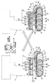
本発明を実施の形態の一例に基づいて詳述すると、本発明に係る電動工具は、インパクトドライバー等の工具本体1と、該工具本体1に着脱自在に装着される電池パック2とからなるもので、複数の直列接続された電池セル13を内蔵している電池パック2は、電池セル13を覆う内ケース15に外ケース14を被せた二重構造となっており、外ケース14の上部が工具本体1への装着部2aとなっている。なお、この装着部2aは充電器への装着に際しても用いられる。
DETAILED DESCRIPTION OF THE INVENTION The present invention will be described in detail based on an example of an embodiment. An electric tool according to the present invention includes a
まず上記装着部2aについて図2及び図3に基づいて説明すると、この装着部2aの左右両サイドに工具本体1への機械的結合のためのL字型係合部4,4’,4”が夫々3つずつ一対設けられている。本例の係合部4,4’,4”は、1個のリブ型係合部4cと3個のL字型係合部4,4’,4”を装着部2aの長手方向Mに沿って隔設することで形成したもので、リブ型係合部4cから長手方向Mの他端側に向かって3個のL字型係合部4,4’,4”が等間隔で突設されている。
First, the
リブ型係合部4cは装着部2aに対して垂直に立設されたものであり、L字型係合部4,4’は、それぞれ装着部2aから垂直に立設された挿入規制部4aと、挿入規制部4aと直交方向に開口した装着保持部4bとで構成されている。また、L字型係合部4”は、上記挿入規制部4aと装着保持部4bと、挿入規制部4aから装着保持部4bへと移動した被係合部5に係脱可能に係合するフック係合部12aとで構成されている。
The rib-
そして図1に示すように、L字型係合部4の内側には第1縦孔6とこれに連なる第1横孔7とが形成され、L字型係合部4’の内側には第2縦孔8とこれに連なる第2横孔9とが形成され、L字型係合部4”の内側には第3縦孔10とこれに連なる第3横孔11とが形成されている。
As shown in FIG. 1, a first
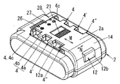
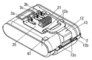
外ケース14と内ケース15との間の中空スペースにはフック12が収納されている。フック12の基端部には、外ケース14にて回動自在に保持される支点部12cが設けられ、フック12の中央側には外ケース14の外部に露出する操作部12bが設けられ、フック12の先端側は二股状に分かれ、両先端にそれぞれフック係合部12aが設けられている。一方のフック係合部12aは前記装着部2aの一方サイドのL字型係合部4”の内側に配置され、他方のフック係合部12aは前記他方サイドのL字型係合部4”の内側に配置される。
A
フック12の操作部12bは、圧縮コイルバネからなる復帰ばね(図示せず)によって外ケース14の内面に接近する方向(図3の上方向)に向かって付勢されており、これによりフック係合部12aの一部がL字型係合部4” の装着保持部4bの内面に弾接している。また、操作部12bを手で押した時、あるいは後述の工具本体1の凸型被係合部5”がフック係合部12aを押し込んだ時、復帰ばねのばね力に抗してフック12が外ケース14の内面から離反する方向(図5の下方向)に回動して、フック係合部12aが挿入規制部4aの底側に埋没することで、凸型被係合部5”をL字型係合部4”に係合させることができる状態となる。
The
なお、L字型係合部4,4’の内側にはそれぞれフック係合部12aは配置されておらず、L字型係合部4,4’と対応する工具本体1のL字型被係合部5,5’はフック12に規制されることなく自由に係合・離脱自在となっている。
In addition, the
また前記外ケース14の装着部2aには、図2に示すように、複数の凹部26〜28が設けられており、これらの奥には、図2に示す内ケース15に固定したプリント基板25に装着される複数の雌端子3a,3b,3cが配置されている。これら雌端子3a,3b,3cは、正負の充放電用端子3a,3bと、検知用の端子3cであり、各凹部26〜28からそれぞれ挿入される複数の雄端子(正負の電源端子、検知用端子)が上記端子3a,3b,3cに各々接続可能とされている。
Further, as shown in FIG. 2, the mounting
一方、電動工具本体1は、図示省略したモータと減速部と出力部とからなり、前記電池パック2が装着される被装着部1aをハンドル部の下面に備え、被装着部1a内には、信号コネクタ91を装着した本体制御回路90や、上記複数の雄端子などが配設されている。
On the other hand, the electric tool
また、被装着部1aの両サイドには、前記電池パック2の装着部2aの両サイドに設けた左右2列の係合部4,4’,4”とそれぞれ対応する左右2列の被係合部5,5’,5”が設けられている。本例の被係合部5,5’,5”は、電池パック2側のL字型係合部4,4’とそれぞれ対応するL字型被係合部5,5’と、L字型係合部4”と対応する凸型被係合部5”とからなる。L字型被係合部5,5’ は、それぞれ、電池パック2側のL字型係合部4,4’に対して引っ掛け方式で噛合可能な縦リブ30と横リブ31とで構成される。
Further, on both sides of the mounted portion 1a, two left and right rows of engaged portions respectively corresponding to the left and right two rows of engaging
次に、装着手順を説明すると、装着以前は、図1に示すように、フック係合部12aがL字型係合部4”の内面に弾接し且つこのフック係合部12aの一部が第3縦孔10に露出した状態となっている。工具本体1の被装着部1aと電池パック2の装着部2aとを互いに押し当てる方向Dに装着すると、工具本体1側の被係合部5,5’,5”が、電池パック2側のL字型係合部4,4’,4”にそれぞれ挿入された状態となる。このとき、凸型被係合部5”がフック係合部12aを押し下げることで、フック12が支点部12cを中心として弧を描くように下向きに回動して、フック係合部12aが挿入規制部4aの底側に埋没した状態となる。
Next, the mounting procedure will be described. Before the mounting, as shown in FIG. 1, the
上記の状態で、前記押し当て方向Dと直交する方向Mに向かって工具本体1に対して電池パック2をずらすと、すべての被係合部5が装着保持部4bに入り込んだ状態となる。このとき、凸型被係合部5”によるフック係合部12aの押し込み力が解除されるために、フック係合部12aはフックバネ12dの働きによって元の位置に復帰する。この結果、フック係合部12aによって凸型被係合部5”の抜け止めがなされ、すべての被係合部5が各装着保持部4bに対して装着状態で保持されることとなり、電池パック2と工具本体1との結合が強固なものとなる。
In the above state, when the
電池パック2を取り外す際は、フック12の操作部12bを指で外部から押すと、フック12が支点部12cを中心として弧を描くように下向きに回動して、フック係合部12aが再び挿入規制部4aの底側に埋没した状態となる。この状態で工具本体1又は電池パック2のどちらか一方をずらすことで、工具本体1と電池パック2とを離脱させることができる。
When the
また本例では、図1に示すように、バッテリーパック2側の第1縦孔6の前後寸法Cと、第2縦孔8の前後寸法Cとが同一寸法とされ、この前後寸法Cに合わせて、電動工具本体1側のL字型被係合部5及びL字型被係合部5’の前後寸法が設定されている。また、バッテリーパック2側の第3縦孔10の前後寸法C1を前記前後寸法Cよりも狭くし、この狭い前後寸法C1に合わせて、電動工具本体1側の凸型被係合部5”の前後寸法が設定されている。このために、電動工具本体1側の凸型被係合部5”はバッテリーパック2側の第3縦孔10のみに挿入可能であり、従って電動工具本体1側の各被係合部5とバッテリーパック2側の各係合部4との誤装着防止が図られている。
Further, in this example, as shown in FIG. 1, the front-rear dimension C of the first
さらに本例では、工具本体1側の左右で総計6個の被係合部5,5’,5”と、電池パック2側の左右で総計6個の係合部4,4’,4”とによって、工具本体1に装着することができる電池パック2の種類を限定することができるようにしている。
Further, in this example, a total of six engaged
すなわち、電池パック2として、直列接続された電池セル13の本数が異なることで定格出力電圧が異なっている複数種のものがあり、工具本体1にしても、電圧による特性が異なるモータを内蔵した複数種のものがある時、工具本体1には適合する定格出力電圧を有する電池パック2を装着して使用することになるが、ここでは適合する定格出力電圧を有する電池パック2の電池容量が無くなった場合に備えて、あるいは一時的に高出力な作業が必要であり、適合する定格出力電圧の電池パック2を装着した状態ではその高出力作業を行うことができない場合に備えて、上記適合する定格出力電圧の電池パック2のほかに、適合する定格出力電圧よりも電池セル13一つ分の電圧差だけ高い定格出力電圧の電池パック2も装着することができるようにしているとともに、他の定格出力電圧の電池パック2は装着することができないようにしている。
That is, as the
具体的には電池パック2の総計6個の係合部4,4’,4”のうちの係合部4の第1縦孔6と、係合部4’の第2縦孔8の左右方向幅を、その電池パック2の定格出力電圧に応じたものとし、工具本体1の被係合部5,5’,5”については被係合部5,5’の左右方向幅を、内蔵するモータの特性に応じたものとしてある。
Specifically, the left and right of the first
図5に一例を示す。適合する電池パック2が14.4Vのものである工具本体1の被係合部5,5’については、右列の被係合部5のみを左右幅の広いものとし、適合する電池パック2が18Vのものである工具本体1の被係合部5,5’については、左列の被係合部5のみを左右幅の広いものとし、適合する電池パック2が21.6Vのものである工具本体1の被係合部5,5’については、右列の被係合部5’のみを左右幅の広いものとしてある。
An example is shown in FIG. For the engaged
そして4本のリチウムイオン電池セル13を直列に接続した定格出力電圧14.4Vの電池パックは、図5(a)に示すように、右列の係合部4の第1縦孔6のみを左右方向幅の広いものとしてあり、5本のリチウムイオン電池セル13を直列に接続した定格出力電圧18Vの電池パックは、図5(b)に示すように、右列の係合部4の第1縦孔6と左列の係合部4の第1縦孔6とが左右方向幅の広いものとしてあり、6本のリチウムイオン電池セル13を直列に接続した定格出力電圧21.6Vの電池パックは、図5(c)に示すように、左列の係合部4の第1縦孔6と右列の係合部4’の第2縦孔8とが左右方向幅の広いものとしてある。
And the battery pack of the rated output voltage 14.4V which connected the four lithium
左右方向幅の広い被係合部5,5’は、左右方向幅の広い係合部4,4’のみに係合させることができ、左右方向幅の狭い係合部4,4’には係合させることができないために、図5に示す例では、適合する電池パック2が14.4Vのものである工具本体1には、定格出力電圧が14.4Vの電池パック2を装着することができる上に、定格出力電圧が18Vの電池パック2も装着することができる。しかし、定格出力電圧が21.6Vの電池パック2は装着することができない。
The engaged
適合する電池パック2が18Vのものである工具本体1には、定格出力電圧が18Vの電池パック2は装着することができる上に、定格出力電圧が21.6Vの電池パック2も装着することができる。しかし、定格出力電圧が14.4Vの電池パック2は装着することができない。
A
適合する電池パック2が21.6Vのものである工具本体1には、定格出力電圧が21.6Vの電池パック2は装着することができるものの、定格出力電圧が14.4V及び18Vの電池パック2は装着することができない。
Although the
つまりは、本例における工具本体1は、適合する定格出力電圧の電池パック2を装着することができるのは当然ながら、そのほかに、同一種の電池セル13(本例の場合はリチウムイオン電池セル13)を備えた電池パック2で且つ電池セル13一つ分の電圧差だけ定格出力電圧が高い電池パック2も装着することができるようになっている。
In other words, the tool
工具本体1に適合する定格出力電圧より高い定格出力電圧の電池パック2を装着した場合、長時間使用するとモータMの焼損などを招く虞があるが、電池セル12一つ分の電圧差程度であれば、短時間での作業であれば問題となることはない。
When the
電動工具は高電圧になるほど出力が大きくなるものの、高電圧対応の電動工具は構造的な耐久性の確保の点からどうしても大きく重くなってしまう。一方、電動工具のユーザーは、使用頻度が高い作業に用いるものについては小型軽量を望むことから、低電圧の電動工具を用いることが多い。しかし、ごくまれに低電圧の電動工具では性能が不足してしまうような高負荷の作業が必要となることがある。この時、本例における電動工具ならば、定格出力電圧が一段高い電池パック2も利用することができるために、高い定格出力電圧の電池パック2に交換することで応ずることができるものである。
Although the output of a power tool increases as the voltage increases, a power tool that supports high voltage is inevitably heavy and heavy in terms of ensuring structural durability. On the other hand, users of power tools often use low-voltage power tools because they desire small size and light weight for work that is frequently used. However, in rare cases, it may be necessary to perform high-load work where the performance of a low-voltage power tool is insufficient. At this time, since the power tool in this example can also use the
なお、ここでは適合する電池パック2の定格電圧出力よりも低い定格出力電圧の電池パック2は装着できないようにした例を示したが、定格電圧出力が一段低い(電池セルの直列本数が一つ少ない)電池パック2も装着することができるようにしてもよいのはもちろんである。性能が落ちることになるが軽作業であれば十分対応することができる。
Although an example in which the
なお、電圧差がかなり大きい電池パック2については、装着できないようにしておくことが好ましい。定格出力電圧がかなり高い電池パック2を装着した時には、モータが焼損するおそれや過大な発熱のおそれがあり、定格出力電圧がかなり低い電池パック2を装着した時には、モータの回転数が低くなりすぎて作業が途中で行えなくなったり作業に支障が生じることになる。
In addition, it is preferable that the
装着することができる電池パック2を制限することを、ここでは複数ある被係合部5,5’、5”及び係合部4,4’、4”の左右幅を異ならせることで行っているが、前後長や高さなどを異ならせることで制限を行うものであってもよい。
In order to limit the
ところで、本来の対応する電池パック2の定格出力電圧と異なる定格出力電圧の電池パック2を装着することができるようにしたものにおいては、電池パック2の過放電防止対策もこの点に応じたものとしなくてはならない。
By the way, in the case where the
このために、ここでは電池パック2を工具本体1に装着した時、電池パック2の種別を工具本体1側で識別して、過放電防止を電池パック2の種別に応じて切り換えることができるようにしている。
Therefore, here, when the
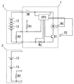
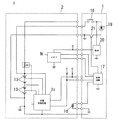
すなわち、図4に示すように、駆動源としてのモータMを内蔵するとともに電池パック2を電源として動作する工具本体1は、操作用のトリガースイッチSWや上記モータMの動作を制御する制御回路CPUと駆動用のスイッチング素子Q1のほかに、回転数センサーNSと温度センサーTSとをハウジング内に備えており、温度センサーTSはスイッチング素子Q1やモータMの近傍に設置されている。
That is, as shown in FIG. 4, the tool
上記制御回路CPUは、回転数センサーNSから回転数情報を、温度センサーTSから温度情報を取得するほか、モータMの負荷を電流検出抵抗Rcの両端電圧から負荷電流値として検出するものであり、また装着される電池パック2の種別情報と、負荷時の電池電圧とを検出することができるものとなっている。
The control circuit CPU acquires rotation speed information from the rotation speed sensor NS and temperature information from the temperature sensor TS, and detects the load of the motor M as a load current value from the voltage across the current detection resistor Rc. The type information of the
内蔵する電池セル13の直列本数が異なる複数種の電池パック2は、内蔵する電池セル13の直列本数に応じた抵抗値を有する抵抗R2を備えており、工具本体1に電池パック2を装着した時、工具本体1の制御回路CPUは、抵抗R1と上記抵抗R2との分圧抵抗から、装着された電池パック2の電池セル13の直列本数(定格出力電圧)の違いによる種別を識別することができるものとなっている。この電池パック2の種別識別は、電池パック2側に設けた不揮発性メモリに種別毎の識別コードを書き込んでおき、電池パック2を工具本体1に装着した時、電池電圧種類識別手段を兼ねている制御回路CPUが上記識別コードを読み出すことで行うものであってもよい。
The plurality of types of
そして、この工具本体1の制御回路CPUは、放電時の電池パック2の出力電圧を検出してこの電圧が閾値まで低下すればモータMを停止させることで過放電防止を工具本体1側でも行っているのであるが、上記制御回路CPUには、電池パック2の種別毎の閾値をテーブルとして持たせており、装着された電池パック2の種別情報を基に、制御回路CPUは上記テーブルから装着された電池パック2に適合した閾値を読み出し、この閾値を基に上記過放電防止制御を行う。装着された電池パック2の定格出力電圧に応じた閾値で放電停止制御を行うために、どの定格出力電圧の電池パック2を装着した時にも、各電池パック2の容量一杯を用いて作業を行うことができる
また、適合する定格出力電圧よりも高い定格出力電圧の電池パック2を装着した場合、高出力を得られるだけでなく、モータMの発熱量の増加やモータMによって駆動される駆動部の負担が大きくなり、この状態で長時間動作させたならば、工具本体1の寿命が短くなってしまう。この点からすれば、適合する定格出力電圧よりも高い定格出力電圧の電池パック2が装着された時には、制御回路CPUは上記識別情報からこの点を検出してモータMの出力を制限した駆動を行うものとするのが好ましい。この制限は、モータMがブラシモータである場合、PWM制御で行うことができる。
Then, the control circuit CPU of the
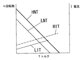
図6はモータMの回転数−トルク(NT)特性と電流−トルク(IT)特性とを示しており、図中HNTは高電圧で駆動した時のNT特性、HITは高電圧で駆動した時のIT特性、LHTは低電圧(適合する定格出力電圧)で駆動した時のNT特性、LITは低電圧で駆動した時のIT特性である。高電圧で駆動した時の方が回転数もトルクも大きくなり、その分、出力だけでなく発熱も大きくなる。 FIG. 6 shows the rotational speed-torque (NT) characteristics and current-torque (IT) characteristics of the motor M. In the figure, HNT is NT characteristics when driven at a high voltage, and HIT is driven at a high voltage. IT characteristics, LHT is NT characteristics when driven at a low voltage (appropriate rated output voltage), and LIT is IT characteristics when driven at a low voltage. When driven at a high voltage, the number of revolutions and torque increase, and not only the output but also heat generation increases.
このために通常であれば、モータMや駆動部分の設計を高電圧でも耐える構造にしなくてはならないが、この場合、工具本体1の大型化を招いてしまう。このために、高電圧の電池パック2が装着された時には、PWM制御によって入力電圧の平均が適合する電圧の電池パック2を装着した時の入力電圧と同じになるようにする。
For this reason, normally, the design of the motor M and the drive portion must be designed to withstand even a high voltage, but in this case, the
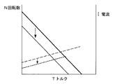
具体的には、電池パックPの識別情報を取得した制御回路CPUは、モータ電流及び電池電圧を測定し、適合する電圧の電池パック2(及びそれよりも定格出力電圧が低い電池パック2)が装着されている時は、特に制限を行わず、高電圧の電池パック2が装着されている時は、適合する電池パック2が装着されている時に得られる最大出力付近の出力になるようにPWM制御を行うことで、図7に示すように、NT特性及びIT特性が図6におけるLHT及びLITと同じにするのである。
Specifically, the control circuit CPU that has acquired the identification information of the battery pack P measures the motor current and the battery voltage, and finds a
上記のような制限を加えることは、予め電圧と電流のテーブルを設けておき、このテーブルを元にNT特性やIT特性のどの位置にあるかを判断し、電圧に対する電流をPWM制御で制限したり、あるいは予め回転数と電流のテーブルを設けておき、このテーブルを元にNT特性やIT特性のどの位置にあるかを判断し、回転数に対する電流をPWM制御で制限することで行うことができる。また温度情報を参照して、温度が所定値を越えた時のみ、上記制限を行うものとしてもよい。 To apply the above restrictions, a voltage and current table is prepared in advance, and based on this table, the position of the NT characteristic or IT characteristic is determined, and the current against the voltage is limited by PWM control. Alternatively, a table of rotation speed and current is provided in advance, based on this table, it is determined where the NT characteristic or IT characteristic is, and the current with respect to the rotation speed is limited by PWM control. it can. Further, referring to the temperature information, the above-described restriction may be performed only when the temperature exceeds a predetermined value.
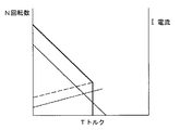
このほか、検出されたモータ電流から発熱が低電圧の電池パック2の装着時と同等になるようにPWM制御したり、出力トルクが低電圧パック2の装着時と同等になるようにPWM制御するものであってもよい。発熱の抑止が重要であれば前者が好ましく、トルクを低減して駆動部分のストレスを低減することを重要視するのであれば後者が好ましい。図8は高負荷による発熱を抑えるために出力を制限(負荷電流の上限を制限)した場合を示しており、図9はトルクを抑えるために出力を制限(トルクの上限を制限)した場合を示している。
In addition, PWM control is performed so that the heat generation from the detected motor current is equivalent to that when the low
更には、高電圧の電池パック2を装着して高電圧をモータMに印加する場合、高回転による回転軸の焼き付きや騒音の低減のために回転数の上限を制限するようにしてもよい。
Furthermore, when the high
回転数の制限は、予め電圧と電流のテーブルを設けておき、このテーブルを基にNT特性やIT特性のどの位置にあるかを判断し、電圧に対する電流をPWM制御で制限することや、予め回転数と電流のテーブルを設けておき、このテーブルを基にNT特性やIT特性のどの位置にあるかを判断し、回転数に対する電流をPWM制御で制限することで行うこともできる。 To limit the number of revolutions, a voltage and current table is prepared in advance, and based on this table, the position of the NT characteristic or IT characteristic is determined, and the current with respect to the voltage is limited by PWM control. It is also possible to provide a table of rotation speed and current, determine the position of the NT characteristic or IT characteristic based on this table, and limit the current with respect to the rotation speed by PWM control.
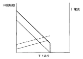
また回転数のみを測定し、回転数が所定回転数を超えないようにPWM制御で制限していくようにしてもよい。図10は最高回転数を低減させた場合を示している。 Alternatively, only the rotational speed may be measured and limited by PWM control so that the rotational speed does not exceed a predetermined rotational speed. FIG. 10 shows a case where the maximum rotational speed is reduced.
モータMがブラシモータではなく、ブラシレスモータである場合は、次のような制御で出力制限を行うようにしてもよい。 When the motor M is not a brush motor but a brushless motor, the output may be limited by the following control.
すなわち、3相のブラシレスモータの駆動については、UVW相のうちの1相は電流が流れない120°通電のほか、120°通電よりも通電期間を長くして転流の前後でオーバーラップ期間(この期間はUVW相全てに電流が流れる)を設けたオーバーラップ通電、さらには正弦波駆動などがあり、後者ほどモータの誘起電圧波形に近づくためにモータの出力や効率が向上する。なお、120°通電とオーバーラップ通電とでは、停動トルク付近においては120°通電に切り換える方が出力が高くなる。 That is, for driving a three-phase brushless motor, in addition to 120 ° energization in which no current flows in one phase of the UVW phase, the energization period is longer than 120 ° energization and the overlap period ( During this period, there is an overlap energization provided with a current flowing in all UVW phases) and a sine wave drive, etc., and the latter is closer to the induced voltage waveform of the motor, so that the output and efficiency of the motor are improved. In the 120 ° energization and the overlap energization, the output is higher when switching to 120 ° energization in the vicinity of the stationary torque.
また、進角制御によっても出力や効率が変化するものであり、進角なしまたは進角量が少ない時よりも進角が多い方が出力が向上する。さらに120°通電とオーバーラップ通電と正弦波駆動では後者の駆動法ほど進角制御による効果も大きくなる。なお、進角制御そのものについては、たとえば特開2003−200363号公報等において公知であるために、ここでは説明を省略する。 Further, the output and efficiency are also changed by the advance angle control, and the output is improved when the advance angle is larger than when there is no advance angle or the amount of advance angle is small. Further, in the 120 ° energization, the overlap energization, and the sine wave drive, the effect of the advance angle control becomes larger as the latter drive method is used. Note that the advance angle control itself is well known in, for example, Japanese Patent Application Laid-Open No. 2003-200363, and the description thereof is omitted here.
このために、装着される電池パック2の種別に応じて上記駆動法や通電角や進角量を切り換えることで、高電圧の電池パック2が装着された時の出力制限を行うことができる。たとえば、低電圧の電池パック2が装着された時には、オーバーラップ量(通電角)が多いオーバーラップ通電とするとともに進角量を多くして出力を大きくとれるようにしておき、高電圧の電池パック2が装着された時には、120°通電あるいはオーバーラップ量の少ないオーバーラップ量とするとともに進角なしとするか進角量を少なくすることで、出力が小さくなるようにしておくのである。このような制御により、高電圧の電池パック2が装着された時の出力を低電圧の電池パック2が装着された時の出力に近づけることができる。
Therefore, by switching the driving method, energization angle, and advance amount according to the type of the
モータMへの負荷が低い時は制限の必要がないためにオーバーラップ通電角制御や進角制御による制限は行わず、モータMの負荷が大きくなった時のみオーバーラップ通電角制御や進角制御による制限を加えるようにしてもよい。 When the load on the motor M is low, there is no need for restriction, so there is no restriction by overlap energization angle control or advance angle control, and overlap energization angle control or advance angle control only when the load on the motor M increases. You may make it add the restriction | limiting by.
たとえば電圧と電流のテーブルを予め設けておき、このテーブルを基にNT特性やIT特性のどの位置にあるかを判断し、電圧に対する電流を制限するためにオーバーラップ通電角制御や進角制御で制限を加えたり、予め回転数と電流のテーブルを設けておき、このテーブルを基にNT特性やIT特性のどの位置にあるかを判断し、回転数に対する電流を制限するためにオーバーラップ通電角制御や進角制御による制限を加えるのである。 For example, a voltage and current table is prepared in advance, and based on this table, it is determined where the NT characteristic or IT characteristic is, and in order to limit the current with respect to the voltage, overlap energization angle control or advance angle control is used. Applying a limit or providing a table of rotation speed and current in advance, judging the position of NT characteristics and IT characteristics based on this table, and overlapping current angle to limit the current with respect to the rotation speed Limits by control and advance control are added.
温度センサーTSで検出される温度が所定値を越える時のみ上記制限を行うようにしてもよい。図11は高電圧の電池パック2が装着された時に高負荷による発熱を抑えるためにオーバーラップ通電角制御や進角制御による出力制限を行い、さらに負荷が大きくなった時は停止させる場合を示している。
The restriction may be performed only when the temperature detected by the temperature sensor TS exceeds a predetermined value. FIG. 11 shows a case where output is limited by overlap energization angle control or advance angle control to suppress heat generation due to a high load when a high-
高電圧の電池パック2を装着した際の高負荷時のオーバーラップ通電角制御や進角制御による出力制限は、低電圧の電池パック2を使用している際と同等レベルのトルクまたは電流に抑えるものとするのが好ましい。
When the high
。図8や図9あるいは図10に示したような負荷電流の制限やトルク上限の制限、最高回転数の制限等も、オーバーラップ通電角制御や進角制御による制限で行うことができる。温度が高くなった時のみ上記制限を行うものであってもよいのはもちろんである。 . The load current limitation, the torque upper limit limitation, the maximum rotation speed limitation, and the like as shown in FIG. 8, FIG. 9, or FIG. 10 can be performed by the overlap energization angle control or the advance angle control. Of course, the restriction may be performed only when the temperature becomes high.
適合する定格出力電圧の電池パック2が装着された時の長時間駆動による発熱等の防止という点では、装着された電池パック2が適合する定格出出力電圧よりも高い定格出力電圧のものであることを判別できた時点で、連続するモータMの駆動時間に制限を加えるようにしてもよい。
In terms of prevention of heat generation due to long-time driving when a
また、電池パック2の識別情報に電池パック2の定格出力電圧に加えて定格容量の情報も含ませておき、装着された電池パック2の定格出力電圧と定格容量との乗算値が所定値以下である場合には、その電池パック2による電源供給でのモータ駆動を許可し、上記乗算値が所定値を越える時には、トリガースイッチSWを操作してもモータMを駆動しないものとしてもよい。なお、使用できない電池パック2が装着された時には報知手段を用いてその旨の報知を行うことが好ましい。
In addition to the rated output voltage of the
図12は電池パック2の識別に関する他例を示しており、ここでは抵抗R2の抵抗値による識別を電池パック2の出力電圧にかかわらず正確に行うことができるように、工具本体1側に定電圧(5V)電源20を設けて、該定電圧電源20から抵抗R2に電圧が印加されるようにしている。
FIG. 12 shows another example relating to the identification of the
図13は電池パック2側に設けた不揮発性メモリNに書き込んだ識別コードを制御回路CPUが読み出すことで電池パック2の識別を行う場合の例を示している。
FIG. 13 shows an example in which the
上記の各例では、同一種の電池セル13で直列接続本数が異なる電池パック2の場合を示したが、異種の電池セル13を備えた電池パック2についても装着使用することができるようにしてもよい。例えばリチウムイオン電池セルを有する定格電圧出力14.4Vの電池パック2が適応する電源である電動工具本体1に対して、ニッケル水素電池セルを有して定格電圧出力が15.6Vもしくは16.8Vである電池パック2を装着使用することができるようにしたり、ニッケル水素電池セルを有する定格電圧出力12Vの電池パック2が適応する電源である工具本体1に対し、リチウムイオン電池セル14を有する定格電圧出力14.4Vの電池パック2を用いることができるようにしてもよいものである。適応する定格出力電圧よりも低い定格出力電圧の異種電池パック2を用いることができるようにしてもよいのはもちろんである。
In each of the above examples, the case of the
1 工具本体
2 電池パック
4,4’、4” 係合部
5,5’、5” 被係合部
13 電池セル
M モータ
SW トリガースイッチ
CPU 制御回路
DESCRIPTION OF
Claims (6)
工具本体が備える上記被装着部は、上記複数種の電池パックのうち、工具本体内のモータの特性に適合する定格出力電圧の電池パックが装着可能となっているとともに、工具本体内のモータの特性に適合する定格出力電圧よりも高い定格出力電圧を有している他の電池パックも装着可能であって、被装着部に装着された電池パックは上記電池端子を介して工具本体側に給電するものであり、且つ工具本体が備える上記被装着部は、工具本体内のモータの特性に適合する定格出力電圧から所定の電圧差を越える定格出力電圧を有する他の電池パックを装着できないものであることを特徴とする電動工具。 One or more battery cells are connected in series or in parallel, and a plurality of types of battery packs having different rated output voltages due to different numbers of battery cells connected in series, and the battery packs are detachably mounted. A tool body having a housing with a mounted portion to be mounted. The tool body is connected to a motor as a power source, a drive unit driven by the motor, and the battery pack via a battery terminal. A power tool that houses a switch as an operation input unit and a control circuit that performs drive control of the motor according to the operation of the switch in the housing,
The mounted portion provided in the tool body can be mounted with a battery pack having a rated output voltage suitable for the characteristics of the motor in the tool body among the plurality of types of battery packs, and the motor in the tool body. Other battery packs with a rated output voltage higher than the rated output voltage suitable for the characteristics can also be installed, and the battery pack mounted on the mounted part feeds power to the tool body via the battery terminal. The above-mentioned mounted part provided in the tool body cannot be mounted with another battery pack having a rated output voltage exceeding a predetermined voltage difference from the rated output voltage suitable for the motor characteristics in the tool body. electric tool, characterized in that there.
電圧による特性が異なるモータを備えている各工具本体の上記被装着部は、上記複数種の電池パックのうち、各工具本体が内蔵しているモータの特性に適合する定格出力電圧の電池パックが装着可能となっているとともに、工具本体内のモータの特性に適合する定格出力電圧よりも高い定格出力電圧を有している他の電池パックも装着可能であって、被装着部に装着された電池パックは上記電池端子を介して工具本体側に給電するものであり、且つ各工具本体が備える上記被装着部は、工具本体内のモータの特性に適合する定格出力電圧から所定の電圧差を越える定格出力電圧を有する他の電池パックを装着できないものであることを特徴とする電動工具。 One or more battery cells are connected in series or in parallel, and a plurality of types of battery packs having different rated output voltages due to different numbers of battery cells connected in series, and the battery packs are detachably mounted. The tool main body includes a plurality of types of tool main bodies each having a mounted portion to be mounted on the housing, and each tool main body includes a motor as a power source, a drive unit driven by the motor, and a battery terminal through the battery terminal. A power tool that houses a switch as an operation input unit to be connected, and a control circuit that performs drive control of the motor in accordance with the operation of the switch, in the housing,
The mating attachment section of the tool body characteristics due to voltage comprises a different motor, among the plural kinds of battery packs, the battery pack fits rated output voltage characteristics of the motor each tool body is built Other battery packs that have a rated output voltage that is higher than the rated output voltage that matches the characteristics of the motor in the tool body can be mounted and mounted on the mounted part. The battery pack supplies power to the tool body via the battery terminal , and the mounted portion provided in each tool body has a predetermined voltage difference from the rated output voltage suitable for the characteristics of the motor in the tool body. An electric tool characterized by being unable to mount another battery pack having a rated output voltage exceeding .
Priority Applications (6)
| Application Number | Priority Date | Filing Date | Title |
|---|---|---|---|
| JP2010073586A JP5491925B2 (en) | 2010-03-26 | 2010-03-26 | Electric tool |
| EP22199105.2A EP4144484B1 (en) | 2010-03-26 | 2011-03-18 | Electric power tool |
| PCT/JP2011/056555 WO2011118523A1 (en) | 2010-03-26 | 2011-03-18 | Electric tool |
| CN201180016157.8A CN102933353B (en) | 2010-03-26 | 2011-03-18 | Electric tool |
| US13/634,361 US9041322B2 (en) | 2010-03-26 | 2011-03-18 | Electric power tool |
| EP11759329.3A EP2554335B1 (en) | 2010-03-26 | 2011-03-18 | Electric tool |
Applications Claiming Priority (1)
| Application Number | Priority Date | Filing Date | Title |
|---|---|---|---|
| JP2010073586A JP5491925B2 (en) | 2010-03-26 | 2010-03-26 | Electric tool |
Publications (2)
| Publication Number | Publication Date |
|---|---|
| JP2011201003A JP2011201003A (en) | 2011-10-13 |
| JP5491925B2 true JP5491925B2 (en) | 2014-05-14 |
Family
ID=44673078
Family Applications (1)
| Application Number | Title | Priority Date | Filing Date |
|---|---|---|---|
| JP2010073586A Active JP5491925B2 (en) | 2010-03-26 | 2010-03-26 | Electric tool |
Country Status (5)
| Country | Link |
|---|---|
| US (1) | US9041322B2 (en) |
| EP (2) | EP4144484B1 (en) |
| JP (1) | JP5491925B2 (en) |
| CN (1) | CN102933353B (en) |
| WO (1) | WO2011118523A1 (en) |
Families Citing this family (40)
| Publication number | Priority date | Publication date | Assignee | Title |
|---|---|---|---|---|
| EP2110921B1 (en) | 2008-04-14 | 2013-06-19 | Stanley Black & Decker, Inc. | Battery management system for a cordless tool |
| US9793724B2 (en) * | 2010-01-11 | 2017-10-17 | A123 Systems Llc | System and method for monitoring and balancing voltage of individual battery cells within a battery pack |
| JP5461221B2 (en) | 2010-02-12 | 2014-04-02 | 株式会社マキタ | Electric tool powered by multiple battery packs |
| JP5432761B2 (en) * | 2010-02-12 | 2014-03-05 | 株式会社マキタ | Electric tool powered by multiple battery packs |
| DE102010063077A1 (en) * | 2010-12-14 | 2012-06-14 | Robert Bosch Gmbh | Hand tool battery device |
| CN102632486B (en) * | 2012-04-12 | 2015-05-20 | 南京德朔实业有限公司 | Electric tool |
| JP5956245B2 (en) * | 2012-05-11 | 2016-07-27 | 株式会社マキタ | Battery pack and electric device system |
| JP6032400B2 (en) * | 2012-08-15 | 2016-11-30 | 日立工機株式会社 | Chainsaw |
| JP6023662B2 (en) * | 2013-05-31 | 2016-11-09 | 株式会社マキタ | Electric machinery and attachments |
| US10027078B2 (en) * | 2014-01-02 | 2018-07-17 | Sears Brands, L.L.C. | Slide battery and power tool for use with both slide and post batteries |
| USD741557S1 (en) | 2014-01-15 | 2015-10-20 | Milwaukee Electric Tool Corporation | Dust collector |
| USD742081S1 (en) | 2014-01-15 | 2015-10-27 | Milwaukee Electric Tool Corporation | Dust collector |
| GB201403971D0 (en) | 2014-03-06 | 2014-04-23 | 7Rdd Ltd | Portable power supply improvements |
| US9893384B2 (en) | 2014-05-18 | 2018-02-13 | Black & Decker Inc. | Transport system for convertible battery pack |
| EP3427901B1 (en) | 2014-05-18 | 2020-03-11 | Black & Decker, Inc. | Convertible battery pack for power tool |
| DE102014211046A1 (en) | 2014-06-10 | 2015-12-17 | Robert Bosch Gmbh | System comprising at least one electronically commutated electric motor of a defined size and a rechargeable battery of at least one voltage class |
| JP6354080B2 (en) * | 2014-09-11 | 2018-07-11 | 工機ホールディングス株式会社 | Electric tool |
| JP2016055401A (en) * | 2014-09-12 | 2016-04-21 | パナソニックIpマネジメント株式会社 | Impact rotary tool |
| CN106450071B (en) * | 2015-08-04 | 2019-08-06 | 南京德朔实业有限公司 | Battery pack and its with the combination of electric tool and the method for connecting them |
| DE102016003150A1 (en) * | 2016-03-16 | 2017-09-21 | Andreas Stihl Ag & Co. Kg | Hand-operated implement with an electric motor |
| JP6764255B2 (en) * | 2016-05-18 | 2020-09-30 | 株式会社マキタ | Electric work machine |
| EP3376558A4 (en) * | 2016-10-31 | 2019-09-11 | Koki Holdings Co., Ltd. | BATTERY PACK, ELECTRICAL DEVICE USING BATTERY PACK, AND ELECTRICAL DEVICE SYSTEM |
| US10491020B2 (en) * | 2016-12-22 | 2019-11-26 | Milwaukee Electric Tool Corporation | Power source for burst operation |
| WO2018119256A1 (en) | 2016-12-23 | 2018-06-28 | Black & Decker Inc. | Cordless power tool system |
| US10926368B2 (en) * | 2017-09-27 | 2021-02-23 | Ingersoll-Rand Industrial U.S., Inc. | Part illumination status lights |
| JP6952261B2 (en) * | 2017-11-10 | 2021-10-20 | パナソニックIpマネジメント株式会社 | Electric tool |
| JP2019155485A (en) * | 2018-03-07 | 2019-09-19 | パナソニックIpマネジメント株式会社 | Power tool |
| US10630095B1 (en) * | 2019-04-02 | 2020-04-21 | Ross Kanarek | Voltage regulating apparatus for a battery pack |
| US11581154B2 (en) | 2019-06-07 | 2023-02-14 | Techtronic Cordless Gp | Battery lock out for power tool |
| GB201911425D0 (en) * | 2019-08-09 | 2019-09-25 | 7Rdd Ltd | Power tool system incorporating a power tool and a battery pack platform for use to supply power to operate a power tool |
| EP3806273A1 (en) | 2019-10-11 | 2021-04-14 | Black & Decker Inc. | Power tool receiving different capacity batttery packs |
| CN110912240B (en) * | 2019-12-12 | 2025-09-16 | 格力博(江苏)股份有限公司 | Adapter and electric tool system |
| KR102402233B1 (en) * | 2020-07-16 | 2022-05-30 | 계양전기 주식회사 | Battery connection terminal module for power tools |
| CN112820998A (en) * | 2020-07-27 | 2021-05-18 | 浙江动一新能源动力科技股份有限公司 | Multipurpose battery pack |
| EP4030528B1 (en) * | 2021-01-15 | 2025-03-12 | Andreas Stihl AG & Co. KG | Battery pack, system and use of a battery pack |
| US20230318105A1 (en) * | 2022-03-31 | 2023-10-05 | Milwaukee Electric Tool Corporation | Battery pack |
| US12570507B2 (en) | 2022-06-07 | 2026-03-10 | Vis, Llc | Floor service jack |
| US11735841B1 (en) | 2022-09-02 | 2023-08-22 | Ross Kanarek | Mount plate for audiovisual devices |
| US11770012B1 (en) | 2022-10-20 | 2023-09-26 | Ross Kanarek | Device, system, and method of charging a battery for audiovisual equipment |
| US12427595B2 (en) | 2022-10-26 | 2025-09-30 | Vis, Llc | Soldering tool with orientation safety control |
Family Cites Families (11)
| Publication number | Priority date | Publication date | Assignee | Title |
|---|---|---|---|---|
| DE3742268A1 (en) * | 1987-12-12 | 1989-06-22 | Licentia Gmbh | ELECTRIC TOOL WITH A DEVICE FOR RECEIVING AND HOLDING BATTERY PACKS IN AND / OR ON THE TOOL HOUSING |
| JP3915376B2 (en) * | 2000-07-07 | 2007-05-16 | 日立工機株式会社 | Storage battery and power tool system |
| JP2003200363A (en) | 2001-12-26 | 2003-07-15 | Makita Corp | Battery type power tool |
| JP2005040996A (en) | 2003-07-23 | 2005-02-17 | Toyobo Co Ltd | Organic fiber reinforced resin pellet, its production method and resin molded product |
| DE10348693B4 (en) * | 2003-10-16 | 2009-06-04 | Hilti Aktiengesellschaft | Electrical connection device for hand tool accessories |
| US20050218867A1 (en) * | 2004-03-31 | 2005-10-06 | Phillips Steven J | Battery pack - cordless power device interface system |
| JP4462112B2 (en) * | 2005-05-26 | 2010-05-12 | パナソニック電工株式会社 | Electric tool |
| JP2007144813A (en) * | 2005-11-28 | 2007-06-14 | Nidec Shibaura Corp | Mold for producing power tool |
| JP5574138B2 (en) * | 2006-09-19 | 2014-08-20 | 日立工機株式会社 | Adapter, combination of battery pack and adapter, and electric tool equipped with them |
| CA2602930C (en) * | 2006-09-19 | 2013-08-06 | Hitachi Koki Co., Ltd. | Adaptor, assembly of battery pack and adaptor, and electric tool with the same |
| JP4968624B2 (en) * | 2006-09-19 | 2012-07-04 | 日立工機株式会社 | Adapter, combination of battery pack and adapter, and electric tool equipped with them |
-
2010
- 2010-03-26 JP JP2010073586A patent/JP5491925B2/en active Active
-
2011
- 2011-03-18 EP EP22199105.2A patent/EP4144484B1/en active Active
- 2011-03-18 CN CN201180016157.8A patent/CN102933353B/en active Active
- 2011-03-18 US US13/634,361 patent/US9041322B2/en active Active
- 2011-03-18 WO PCT/JP2011/056555 patent/WO2011118523A1/en not_active Ceased
- 2011-03-18 EP EP11759329.3A patent/EP2554335B1/en active Active
Also Published As
| Publication number | Publication date |
|---|---|
| EP2554335A4 (en) | 2018-04-18 |
| EP2554335A1 (en) | 2013-02-06 |
| JP2011201003A (en) | 2011-10-13 |
| EP2554335B1 (en) | 2023-03-08 |
| WO2011118523A1 (en) | 2011-09-29 |
| CN102933353A (en) | 2013-02-13 |
| EP4144484A1 (en) | 2023-03-08 |
| US20130002175A1 (en) | 2013-01-03 |
| CN102933353B (en) | 2016-03-30 |
| EP4144484B1 (en) | 2024-05-01 |
| US9041322B2 (en) | 2015-05-26 |
Similar Documents
| Publication | Publication Date | Title |
|---|---|---|
| JP5491925B2 (en) | Electric tool | |
| US20240055674A1 (en) | Battery pack, electric device using battery pack, and electric device system | |
| US10587134B2 (en) | Battery pack | |
| US10348110B2 (en) | Battery pack | |
| JP5476177B2 (en) | Electric tool | |
| US11207770B2 (en) | Power tool operation recording and playback | |
| US20190259985A1 (en) | Battery pack, electrical device using battery pack, and electrical device system | |
| CN201227812Y (en) | Adapters for electric tool without cable | |
| US8154248B2 (en) | Signal for pre-charge selection in lithium charging and discharge control/pre-charge function | |
| EP2175514A1 (en) | Shared Control of Thermistor and Dual Purpose Thermistor Line | |
| CN102712088A (en) | Power tool and battery pack for use therein | |
| JP2006326765A (en) | Power tool | |
| JP6743443B2 (en) | Battery pack and power tool | |
| JP4999284B2 (en) | Battery pack, power tool and charger | |
| JP5288563B2 (en) | Electric tool | |
| JP2013105726A (en) | Battery pack and battery cover | |
| US20150002074A1 (en) | Electronic speed controller with automatic detection for type of battery | |
| CN120380647A (en) | Energy storage unit for an electrical device | |
| CN119895622A (en) | Energy storage unit for an electrical consumer | |
| KR102439614B1 (en) | Battery Pack For Electric Tool | |
| KR102439613B1 (en) | Battery Pack For Electric Tool | |
| US20230275295A1 (en) | Electric device system and battery pack | |
| CN106383318B (en) | A kind of battery detection module of the battery block of electric hand tool | |
| JP3130885U (en) | Battery power supply | |
| CN118231804A (en) | Energy storage unit for an electrical consumer and method for producing an energy storage unit |
Legal Events
| Date | Code | Title | Description |
|---|---|---|---|
| A621 | Written request for application examination |
Free format text: JAPANESE INTERMEDIATE CODE: A621 Effective date: 20120209 |
|
| A711 | Notification of change in applicant |
Free format text: JAPANESE INTERMEDIATE CODE: A712 Effective date: 20130513 |
|
| A131 | Notification of reasons for refusal |
Free format text: JAPANESE INTERMEDIATE CODE: A131 Effective date: 20130806 |
|
| A521 | Request for written amendment filed |
Free format text: JAPANESE INTERMEDIATE CODE: A523 Effective date: 20131007 |
|
| TRDD | Decision of grant or rejection written | ||
| A01 | Written decision to grant a patent or to grant a registration (utility model) |
Free format text: JAPANESE INTERMEDIATE CODE: A01 Effective date: 20140204 |
|
| A61 | First payment of annual fees (during grant procedure) |
Free format text: JAPANESE INTERMEDIATE CODE: A61 Effective date: 20140228 |
|
| R151 | Written notification of patent or utility model registration |
Ref document number: 5491925 Country of ref document: JP Free format text: JAPANESE INTERMEDIATE CODE: R151 |