JP5490610B2 - Cleaning method - Google Patents
Cleaning method Download PDFInfo
- Publication number
- JP5490610B2 JP5490610B2 JP2010118371A JP2010118371A JP5490610B2 JP 5490610 B2 JP5490610 B2 JP 5490610B2 JP 2010118371 A JP2010118371 A JP 2010118371A JP 2010118371 A JP2010118371 A JP 2010118371A JP 5490610 B2 JP5490610 B2 JP 5490610B2
- Authority
- JP
- Japan
- Prior art keywords
- cleaning liquid
- nozzle
- workpiece
- work
- cleaning
- Prior art date
- Legal status (The legal status is an assumption and is not a legal conclusion. Google has not performed a legal analysis and makes no representation as to the accuracy of the status listed.)
- Active
Links
- 238000004140 cleaning Methods 0.000 title claims description 488
- 238000000034 method Methods 0.000 title claims description 61
- 239000007788 liquid Substances 0.000 claims description 336
- 239000007921 spray Substances 0.000 claims description 95
- 230000002093 peripheral effect Effects 0.000 claims description 93
- 238000003892 spreading Methods 0.000 claims description 30
- 239000000758 substrate Substances 0.000 claims description 19
- 238000005507 spraying Methods 0.000 claims description 15
- 239000011295 pitch Substances 0.000 description 10
- 238000002347 injection Methods 0.000 description 8
- 239000007924 injection Substances 0.000 description 8
- 108091008695 photoreceptors Proteins 0.000 description 5
- 239000011159 matrix material Substances 0.000 description 4
- 239000000243 solution Substances 0.000 description 3
- 238000005406 washing Methods 0.000 description 3
- 239000000956 alloy Substances 0.000 description 2
- 229910045601 alloy Inorganic materials 0.000 description 2
- 229910052782 aluminium Inorganic materials 0.000 description 2
- XAGFODPZIPBFFR-UHFFFAOYSA-N aluminium Chemical compound [Al] XAGFODPZIPBFFR-UHFFFAOYSA-N 0.000 description 2
- 238000005520 cutting process Methods 0.000 description 2
- 230000015572 biosynthetic process Effects 0.000 description 1
- 238000005237 degreasing agent Methods 0.000 description 1
- 239000013527 degreasing agent Substances 0.000 description 1
- 230000000694 effects Effects 0.000 description 1
- 239000012530 fluid Substances 0.000 description 1
- 230000002452 interceptive effect Effects 0.000 description 1
- 229910052751 metal Inorganic materials 0.000 description 1
- 239000002184 metal Substances 0.000 description 1
- 230000000630 rising effect Effects 0.000 description 1
- 238000006748 scratching Methods 0.000 description 1
- 230000002393 scratching effect Effects 0.000 description 1
- XLYOFNOQVPJJNP-UHFFFAOYSA-N water Substances O XLYOFNOQVPJJNP-UHFFFAOYSA-N 0.000 description 1
Images


Classifications
-
- B—PERFORMING OPERATIONS; TRANSPORTING
- B08—CLEANING
- B08B—CLEANING IN GENERAL; PREVENTION OF FOULING IN GENERAL
- B08B3/00—Cleaning by methods involving the use or presence of liquid or steam
- B08B3/02—Cleaning by the force of jets or sprays
- B08B3/022—Cleaning travelling work
-
- G—PHYSICS
- G03—PHOTOGRAPHY; CINEMATOGRAPHY; ANALOGOUS TECHNIQUES USING WAVES OTHER THAN OPTICAL WAVES; ELECTROGRAPHY; HOLOGRAPHY
- G03G—ELECTROGRAPHY; ELECTROPHOTOGRAPHY; MAGNETOGRAPHY
- G03G21/00—Arrangements not provided for by groups G03G13/00 - G03G19/00, e.g. cleaning, elimination of residual charge
- G03G21/0005—Arrangements not provided for by groups G03G13/00 - G03G19/00, e.g. cleaning, elimination of residual charge for removing solid developer or debris from the electrographic recording medium
- G03G21/0052—Arrangements not provided for by groups G03G13/00 - G03G19/00, e.g. cleaning, elimination of residual charge for removing solid developer or debris from the electrographic recording medium using an air flow; Details thereof, e.g. nozzle structure
Landscapes
- Physics & Mathematics (AREA)
- General Physics & Mathematics (AREA)
- Cleaning By Liquid Or Steam (AREA)
- Photoreceptors In Electrophotography (AREA)
- Nozzles (AREA)
Description
本発明は、感光ドラム基体等のワークを洗浄する洗浄方法及び洗浄装置に関する。 The present invention relates to a cleaning method and a cleaning apparatus for cleaning a workpiece such as a photosensitive drum substrate.
複写機、プリンタ、ファクシミリ装置等の電子写真装置の感光ドラムに用いられる筒状基体、即ち感光ドラム基体は、アルミニウム又はその合金等の金属製であり、その外周面に有機感光体層が形成される。基体の軸方向各端面の周縁部には切削により面取り加工が施されている。 A cylindrical substrate used for a photosensitive drum of an electrophotographic apparatus such as a copying machine, a printer, or a facsimile machine, that is, a photosensitive drum substrate is made of metal such as aluminum or an alloy thereof, and an organic photoreceptor layer is formed on an outer peripheral surface thereof. The A chamfering process is performed on the peripheral edge portion of each end face in the axial direction of the base body by cutting.
この基体では、良好な有機感光体層を形成できるようにするため、有機感光体層の形成の前に基体の全面が洗浄される。この洗浄により、基体に付着していた切粉、油等の付着物が除去される。 In this substrate, the entire surface of the substrate is washed before the formation of the organic photoreceptor layer so that a good organic photoreceptor layer can be formed. By this cleaning, deposits such as chips and oil attached to the substrate are removed.
基体の洗浄方法を開示した公知文献として、例えば特開2006−106380号公報(特許文献1)がある。この公報では、基体の洗浄方法として、スプレーノズルから噴射された洗浄液で基体を洗浄するスプレー洗浄が採用されている。その他の公知文献としては、特開2003−262964号公報(特許文献2)等がある。 As a known document disclosing a method for cleaning a substrate, there is, for example, Japanese Patent Laid-Open No. 2006-106380 (Patent Document 1). In this publication, a spray cleaning method for cleaning a substrate with a cleaning liquid sprayed from a spray nozzle is employed as a substrate cleaning method. Other known documents include Japanese Patent Laid-Open No. 2003-262964 (Patent Document 2).
而して、一般に、感光ドラム基体等のワークの下面をスプレー洗浄方法により洗浄する場合には、ワークをワーク支持部材で支持しておき、ワークの下側に配置されたスプレーノズルから洗浄液を上向きに噴射する。これにより、ワークの下面が下洗浄液で洗浄される。 Thus, in general, when the lower surface of a workpiece such as a photosensitive drum base is cleaned by a spray cleaning method, the workpiece is supported by a workpiece support member, and the cleaning liquid is directed upward from a spray nozzle disposed on the lower side of the workpiece. To spray. Thereby, the lower surface of the workpiece is cleaned with the lower cleaning liquid.
しかるに、この洗浄方法によれば、ワークの下面の洗浄の際に、下ノズルから噴射された下洗浄液がワークの下面に当たることで、ワークがワーク支持部材から浮き上がることがあった。このようになると、ワークの下面を十分に洗浄することが困難になるし、更には、浮き上がったワークの下面に下洗浄液が当たらなくなるとワークが自重で下降してワーク支持部材に衝突し、ワークの下面に傷が付く虞があった。 However, according to this cleaning method, when the lower surface of the workpiece is cleaned, the lower cleaning liquid sprayed from the lower nozzle hits the lower surface of the workpiece, so that the workpiece may be lifted from the workpiece support member. In this case, it becomes difficult to sufficiently clean the lower surface of the workpiece. Furthermore, if the lower cleaning liquid does not hit the lower surface of the workpiece that has been lifted, the workpiece is lowered by its own weight and collides with the workpiece support member. There was a risk of scratching the bottom surface.
本発明は、上述した技術背景に鑑みてなされたもので、その目的は、感光ドラム基体等のワークの下面をスプレー洗浄する際のワークの浮き上がりを防止することができる洗浄方法及び該洗浄方法に用いられる洗浄装置を提供することにある。 The present invention has been made in view of the above-described technical background, and an object of the present invention is to a cleaning method and a cleaning method capable of preventing the workpiece from being lifted when the lower surface of the workpiece such as a photosensitive drum substrate is spray cleaned. It is to provide a cleaning device to be used.
本発明は以下の手段を提供する。 The present invention provides the following means.
[1] ワークの上側に配置された上スプレーノズルから上洗浄液を下向きに噴射し且つワークの下側に配置された下スプレーノズルから下洗浄液を上向きに噴射した状態で、ワークを前記上下両ノズルに対して相対的に水平方向に移動させることにより、ワークの上面及び外周面のうち少なくとも上面を前記上洗浄液で洗浄するとともに、ワークの下面を前記下洗浄液で洗浄する洗浄工程を含み、
前記洗浄工程では、前記上ノズル及び前記下ノズルからそれぞれ前記上洗浄液及び前記下洗浄液を、下洗浄液がワークの下面に当たるときは上洗浄液が必ずワークの上面及び外周面からなる領域の少なくとも一部に当たるように噴射することを特徴とする洗浄方法。
[1] In the state where the upper cleaning liquid is jetted downward from the upper spray nozzle arranged on the upper side of the work and the lower cleaning liquid is jetted upward from the lower spray nozzle arranged on the lower side of the work, A cleaning step of cleaning at least the upper surface of the upper surface and the outer peripheral surface of the work with the upper cleaning liquid and cleaning the lower surface of the work with the lower cleaning liquid by moving in a horizontal direction relative to
In the cleaning step, the upper cleaning liquid and the lower cleaning liquid are applied from the upper nozzle and the lower nozzle, respectively, and when the lower cleaning liquid hits the lower surface of the work, the upper cleaning liquid always hits at least a part of the region formed by the upper surface and the outer peripheral surface of the work. The cleaning method is characterized by spraying.
[2] 平面視において、前記上ノズルの配置位置と前記下ノズルの配置位置とがずれており、
前記洗浄工程では、前記上ノズル及び前記下ノズルからそれぞれ前記上洗浄液及び前記下洗浄液を、上洗浄液と下洗浄液が互いに干渉しないように噴射する前項1記載の洗浄方法。
[2] In a plan view, the arrangement position of the upper nozzle is shifted from the arrangement position of the lower nozzle,
The cleaning method according to claim 1, wherein, in the cleaning step, the upper cleaning liquid and the lower cleaning liquid are sprayed from the upper nozzle and the lower nozzle, respectively, so that the upper cleaning liquid and the lower cleaning liquid do not interfere with each other.
[3] 前記上ノズルから噴射される前記上洗浄液の単位時間当たりの噴射流量が、前記下ノズルから噴射される前記下洗浄液の単位時間当たりの噴射流量よりも大きい前項1又は2記載の洗浄方法。
[3] The cleaning method according to
[4] ワークは筒状であり且つその軸を鉛直にして配置されており、
前記洗浄工程では、ワークの上面、外周面及び内周面を前記上洗浄液で洗浄するとともに、ワークの下面及び内周面を前記下洗浄液で洗浄する前項1〜3のいずれかに記載の洗浄方法。
[4] The workpiece is cylindrical and arranged with its axis vertical.
The cleaning method according to any one of Items 1 to 3, wherein in the cleaning step, the upper surface, outer peripheral surface, and inner peripheral surface of the workpiece are cleaned with the upper cleaning liquid, and the lower surface and inner peripheral surface of the workpiece are cleaned with the lower cleaning liquid. .
[5] 前記上ノズル及び前記下ノズルはそれぞれフラットスプレーノズルから構成されており、
前記洗浄工程では、前記上ノズル及び前記下ノズルからそれぞれ前記上洗浄液及び前記下洗浄液を扇形膜状に噴射する前項1〜4のいずれかに記載の洗浄方法。
[5] The upper nozzle and the lower nozzle are each composed of a flat spray nozzle,
5. The cleaning method according to any one of items 1 to 4, wherein, in the cleaning step, the upper cleaning liquid and the lower cleaning liquid are sprayed in a fan-shaped film form from the upper nozzle and the lower nozzle, respectively.
[6] 前記洗浄工程では、平面視において、前記上ノズル及び前記下ノズルからそれぞれ前記上洗浄液及び前記下洗浄液を、前記上洗浄液の噴射広がり方向と前記下洗浄液の噴射広がり方向とが互いに平行になるように噴射する前項5記載の洗浄方法。 [6] In the cleaning step, in the plan view, the upper cleaning liquid and the lower cleaning liquid are respectively supplied from the upper nozzle and the lower nozzle, and the jet spreading direction of the upper cleaning liquid and the jet spreading direction of the lower cleaning liquid are parallel to each other. 6. The cleaning method according to 5 above, wherein the jetting is performed.
[7] 平面視において、ワークは、前記ワークの相対移動方向の直交方向に複数個並んで配置されるとともに、
平面視において、前記上ノズルと前記下ノズルは、前記ワークの相対移動方向の直交方向に複数個交互に並んで配置されている前項5又は6記載の洗浄方法。
[7] In plan view, a plurality of workpieces are arranged side by side in a direction orthogonal to the relative movement direction of the workpiece,
7. The cleaning method according to
[8] 平面視において、前記上ノズルは、前記ワークの相対移動領域の外側に配置される一方、前記下ノズルは、前記ワークの相対移動領域の内側に配置されている前項5〜7のいずれかに記載の洗浄方法。 [8] In plan view, the upper nozzle is arranged outside the relative movement area of the workpiece, while the lower nozzle is arranged inside the relative movement area of the workpiece. A cleaning method according to claim 1.
[9] 前記洗浄工程では、平面視において、前記上ノズル及び前記下ノズルからそれぞれ前記上洗浄液及び前記下洗浄液を、上洗浄液及び下洗浄液の噴射広がり方向がともに前記ワークの相対移動方向に対して斜め方向になるように噴射する前項5〜8のいずれかに記載の洗浄方法。 [9] In the cleaning step, in the plan view, the upper cleaning liquid and the lower cleaning liquid are respectively discharged from the upper nozzle and the lower nozzle, and the jet spreading directions of the upper cleaning liquid and the lower cleaning liquid are both relative to the relative movement direction of the workpiece. 9. The cleaning method according to any one of 5 to 8 above, wherein the jetting is performed in an oblique direction.
[10] 平面視において、ワークは、前記ワークの相対移動方向及びその直交方向に複数行及び複数列に並んで配置されており、
前記洗浄工程では、前記上洗浄液が互いに隣り合う2つのワーク行のうち一方のワーク行の少なくとも1個のワークと他方のワーク行の少なくとも1個のワークとに当たるように、前記上洗浄液を噴射する前項5〜9のいずれかに記載の洗浄方法。
[10] In a plan view, the workpieces are arranged in a plurality of rows and a plurality of columns in the relative movement direction of the workpiece and the orthogonal direction thereof,
In the cleaning step, the upper cleaning liquid is sprayed so that the upper cleaning liquid hits at least one work in one work row and at least one work in the other work row among the two work rows adjacent to each other. 10. The cleaning method according to any one of 5 to 9 above.
[11] ワーク配置位置における前記上ノズルから噴射される前記上洗浄液の噴射広がり幅が、ワーク配置位置における前記下ノズルから噴射される前記下洗浄液の噴射広がり幅よりも大きい前項5〜10のいずれかに記載の洗浄方法。
[11] Any one of
[12] 前記下ノズルとワークとの間の鉛直方向の距離が、前記上ノズルとワークとの間の鉛直方向の距離よりも短い前項1〜11のいずれかに記載の洗浄方法。 [12] The cleaning method according to any one of the preceding items 1 to 11, wherein a vertical distance between the lower nozzle and the workpiece is shorter than a vertical distance between the upper nozzle and the workpiece.
[13] 前記ワークは、感光ドラム基体である前項1〜12のいずれかに記載の洗浄方法。 [13] The cleaning method according to any one of items 1 to 12, wherein the workpiece is a photosensitive drum substrate.
[14] ワークの上側に配置されるとともに上洗浄液を下向きに噴射する上スプレーノズルと、
ワークの下側に配置されるとともに下洗浄液を上向きに噴射する下スプレーノズルと、
ワークを前記上下両ノズルに対して相対的に水平方向に移動させる駆動手段と、を備え、
前記上ノズル及び前記下ノズルからそれぞれ前記上洗浄液及び前記下洗浄液が噴射された状態で、前記駆動手段によってワークを相対移動させることにより、ワークの上面及び外周面のうち少なくとも上面を前記上洗浄液で洗浄するとともにワークの下面を前記下洗浄液で洗浄するように構成され、
前記上ノズル及び前記下ノズルからそれぞれ前記上洗浄液及び前記下洗浄液が、下洗浄液がワークの下面に当たるときは上洗浄液が必ずワークの上面及び外周面からなる領域の少なくとも一部に当たるように噴射されることを特徴とする洗浄装置。
[14] An upper spray nozzle that is disposed on the upper side of the work and sprays the upper cleaning liquid downward,
A lower spray nozzle disposed below the workpiece and spraying a lower cleaning liquid upward;
Drive means for moving the workpiece in the horizontal direction relative to the upper and lower nozzles, and
In a state where the upper cleaning liquid and the lower cleaning liquid are respectively ejected from the upper nozzle and the lower nozzle, the work is relatively moved by the driving means, so that at least the upper surface and the outer peripheral surface of the work are covered with the upper cleaning liquid. It is configured to clean the lower surface of the workpiece with the lower cleaning liquid as well as cleaning,
The upper cleaning liquid and the lower cleaning liquid are sprayed from the upper nozzle and the lower nozzle, respectively, so that when the lower cleaning liquid hits the lower surface of the work, the upper cleaning liquid always hits at least a part of the area composed of the upper surface and the outer peripheral surface of the work. A cleaning apparatus characterized by that.
なお、前項[14]の洗浄装置は、更に以下の構成も採用可能である。 In addition, the following structure can also be employ | adopted for the washing | cleaning apparatus of preceding clause [14].
[15] 平面視において、前記上ノズルの配置位置と前記下ノズルの配置位置とがずれており、
前記上ノズル及び前記下ノズルからそれぞれ前記上洗浄液及び前記下洗浄液が、上洗浄液と下洗浄液が互いに干渉しないように噴射される前項14記載の洗浄装置。
[15] In a plan view, the arrangement position of the upper nozzle is shifted from the arrangement position of the lower nozzle,
15. The cleaning apparatus according to 14 above, wherein the upper cleaning liquid and the lower cleaning liquid are sprayed from the upper nozzle and the lower nozzle, respectively, so that the upper cleaning liquid and the lower cleaning liquid do not interfere with each other.
[16] 前記上ノズルから噴射される前記上洗浄液の単位時間当たりの噴射流量が、前記下ノズルから噴射される前記下洗浄液の単位時間当たりの噴射流量よりも大きい前項14又は15記載の洗浄装置。 [16] The cleaning device according to [14] or [15], wherein an injection flow rate per unit time of the upper cleaning liquid injected from the upper nozzle is larger than an injection flow rate per unit time of the lower cleaning liquid injected from the lower nozzle. .
[17] ワークは筒状であり且つその軸を鉛直にして配置されており、
ワークの上面、外周面及び内周面が前記上洗浄液で洗浄されるとともに、ワークの下面及び内周面が前記下洗浄液で洗浄される前項14〜16のいずれかに記載の洗浄装置。
[17] The workpiece is cylindrical and arranged with its axis vertical.
The cleaning apparatus according to any one of Items 14 to 16, wherein an upper surface, an outer peripheral surface, and an inner peripheral surface of a work are cleaned with the upper cleaning liquid, and a lower surface and an inner peripheral surface of the work are cleaned with the lower cleaning liquid.
[18] 前記上ノズル及び前記下ノズルはそれぞれフラットスプレーノズルから構成されており、
前記上ノズル及び前記下ノズルからそれぞれ前記上洗浄液及び前記下洗浄液が扇形膜状に噴射される前項14〜17のいずれかに記載の洗浄装置。
[18] The upper nozzle and the lower nozzle are each composed of a flat spray nozzle,
18. The cleaning device according to any one of items 14 to 17, wherein the upper cleaning liquid and the lower cleaning liquid are ejected in a fan-shaped film form from the upper nozzle and the lower nozzle, respectively.
[19] 平面視において、前記上ノズル及び前記下ノズルからそれぞれ前記上洗浄液及び前記下洗浄液が、前記上洗浄液の噴射広がり方向と前記下洗浄液の噴射広がり方向とが互いに平行になるように噴射される前項18記載の洗浄装置。 [19] In a plan view, the upper cleaning liquid and the lower cleaning liquid are sprayed from the upper nozzle and the lower nozzle, respectively, so that the jet spreading direction of the upper cleaning liquid and the jet spreading direction of the lower cleaning liquid are parallel to each other. 19. The cleaning device according to item 18 above.
[20] 平面視において、ワークは、前記ワークの相対移動方向の直交方向に複数個並んで配置されるとともに、
平面視において、前記上ノズルと前記下ノズルは、前記ワークの相対移動方向の直交方向に複数個交互に並んで配置されている前項18又は19記載の洗浄装置。
[20] In plan view, a plurality of workpieces are arranged side by side in a direction orthogonal to the relative movement direction of the workpiece,
20. The cleaning apparatus according to the above item 18 or 19, wherein when viewed from above, a plurality of the upper nozzles and the lower nozzles are alternately arranged in a direction orthogonal to the relative movement direction of the workpiece.
[21] 平面視において、前記上ノズルは、前記ワークの相対移動領域の外側に配置される一方、前記下ノズルは、前記ワークの相対移動領域の内側に配置されている前項18〜20のいずれかに記載の洗浄装置。 [21] In plan view, the upper nozzle is disposed outside the relative movement region of the workpiece, while the lower nozzle is disposed inside the relative movement region of the workpiece. A cleaning apparatus according to claim 1.
[22] 平面視において、前記上ノズル及び前記下ノズルからそれぞれ前記上洗浄液及び前記下洗浄液が、上洗浄液及び下洗浄液の噴射広がり方向がともに前記ワークの相対移動方向に対して斜め方向になるように噴射される前項18〜21のいずれかに記載の洗浄装置。 [22] When viewed from above, the upper cleaning liquid and the lower cleaning liquid are ejected from the upper nozzle and the lower nozzle, respectively, so that the spray spreading directions of the upper cleaning liquid and the lower cleaning liquid are oblique to the relative movement direction of the workpiece. The cleaning device according to any one of the preceding items 18 to 21, wherein the cleaning device is sprayed on the surface.
[23] 前記ワークは、前記ワークの相対移動方向及びその直交方向に複数行及び複数列に並んで配置されており、
前記上洗浄液が互いに隣り合う2つのワーク行のうち一方のワーク行の少なくとも1個のワークと他方のワーク行の少なくとも1個のワークとに当たるように、前記上洗浄液が噴射される前項18〜22のいずれかに記載の洗浄装置。
[23] The workpieces are arranged in a plurality of rows and a plurality of columns in the relative movement direction of the workpiece and the orthogonal direction thereof,
The preceding items 18 to 22 in which the upper cleaning liquid is jetted so that the upper cleaning liquid hits at least one work in one of the two work lines and at least one work in the other work line. The cleaning apparatus according to any one of the above.
[24] ワーク配置位置における前記上ノズルから噴射される前記上洗浄液の噴射広がり幅が、ワーク配置位置における前記下ノズルから噴射される前記下洗浄液の噴射広がり幅よりも大きい前項18〜23のいずれかに記載の洗浄装置。 [24] Any one of the above items 18 to 23, wherein an ejection spread width of the upper cleaning liquid ejected from the upper nozzle at the work placement position is larger than an ejection spread width of the lower cleaning liquid ejected from the lower nozzle at the work placement position. A cleaning apparatus according to claim 1.
[25] 前記下ノズルとワークとの間の鉛直方向の距離が、前記上ノズルとワークとの間の鉛直方向の距離よりも短い前項14〜24のいずれかに記載の洗浄装置。 [25] The cleaning device according to any one of [14] to [24], wherein a vertical distance between the lower nozzle and the workpiece is shorter than a vertical distance between the upper nozzle and the workpiece.
[26] 前記ワークは、感光ドラム基体である前項14〜25のいずれかに記載の洗浄装置。 [26] The cleaning apparatus according to any one of [14] to [25], wherein the workpiece is a photosensitive drum base.
本発明は以下の効果を奏する。 The present invention has the following effects.
前項[1]の洗浄方法によれば、上ノズル及び下ノズルからそれぞれ上洗浄液及び下洗浄液を、下洗浄液がワークの下面に当たるときは上洗浄液が必ずワークの上面及び外周面からなる領域の少なくとも一部に当たるように噴射することにより、ワークの浮き上がりを防止することができる。これにより、ワークの下面を確実に洗浄することができるし、ワークの下面の傷付きを防止することができる。 According to the cleaning method of [1], the upper cleaning liquid and the lower cleaning liquid are applied from the upper nozzle and the lower nozzle, respectively. When the lower cleaning liquid hits the lower surface of the workpiece, at least one of the regions formed by the upper cleaning liquid and the outer peripheral surface is always required. By spraying so as to hit the part, it is possible to prevent the workpiece from being lifted. Thereby, the lower surface of a workpiece | work can be wash | cleaned reliably and the damage | wound of the lower surface of a workpiece | work can be prevented.
前項[2]の洗浄方法によれば、上ノズル及び下ノズルからそれぞれ上洗浄液及び下洗浄液を、上洗浄液と下洗浄液が互いに干渉しないように噴射することにより、上洗浄液及び下洗浄液の洗浄力をそれぞれ向上させることができる。 According to the cleaning method of [2], the upper cleaning liquid and the lower cleaning liquid are sprayed from the upper nozzle and the lower nozzle, respectively, so that the upper cleaning liquid and the lower cleaning liquid do not interfere with each other. Each can be improved.
前項[3]の洗浄方法によれば、上ノズルからの上洗浄液の噴射流量が、下ノズルからの下洗浄液の噴射流量よりも大きいことにより、ワークの浮き上がりを確実に防止することができる。 According to the cleaning method of [3], the work flow can be reliably prevented from being lifted because the jet flow rate of the upper cleaning liquid from the upper nozzle is larger than the jet flow rate of the lower cleaning liquid from the lower nozzle.
前項[4]の洗浄方法によれば、ワークが小径な筒状であっても当該ワークの全面、即ちワークの上面、外周面、下面及び内周面を洗浄することができる。 According to the cleaning method of [4], the entire surface of the workpiece, that is, the upper surface, outer peripheral surface, lower surface and inner peripheral surface of the workpiece can be cleaned even if the workpiece has a small diameter cylindrical shape.
前項[5]の洗浄方法によれば、上ノズル及び下ノズルはそれぞれフラットスプレーノズルから構成されており、上ノズル及び下ノズルからそれぞれ上洗浄液及び下洗浄液を扇形膜状に噴射することにより、上洗浄液及び下洗浄液の洗浄力をそれぞれ更に向上させることができる。 According to the cleaning method of [5] in the previous section, the upper nozzle and the lower nozzle are each composed of a flat spray nozzle, and the upper cleaning liquid and the lower cleaning liquid are sprayed from the upper nozzle and the lower nozzle, respectively, into a fan-shaped film, thereby The cleaning power of the cleaning liquid and the lower cleaning liquid can be further improved.
前項[6]の洗浄方法によれば、上ノズル及び下ノズルからそれぞれ上洗浄液及び下洗浄液を、上洗浄液の噴射広がり方向と下洗浄液の噴射広がり方向とが互いに平行になるように噴射することにより、上洗浄液と下洗浄液との干渉を確実に防止できるし、更には、上洗浄液と下洗浄液を互いに近接して噴射することができ、これにより、ワークを効果的に洗浄することができるし、洗浄装置の小型化を図ることができる。 According to the cleaning method of [6], the upper cleaning liquid and the lower cleaning liquid are sprayed from the upper nozzle and the lower nozzle, respectively, such that the jet spreading direction of the upper cleaning liquid and the jet spreading direction of the lower cleaning liquid are parallel to each other. The upper cleaning liquid and the lower cleaning liquid can be reliably prevented from interfering with each other, and the upper cleaning liquid and the lower cleaning liquid can be jetted in close proximity to each other, whereby the workpiece can be effectively cleaned, The size of the cleaning device can be reduced.
前項[7]の洗浄方法によれば、複数個のワークを一括して洗浄することができる。 According to the cleaning method of [7], a plurality of workpieces can be cleaned at once.
前項[8]の洗浄方法によれば、上洗浄液でワークの上面及び外周面を確実に洗浄することができるし、ワークが筒状であっても該筒状ワークの下面及び内周面を下洗浄液で確実に洗浄することができる。 According to the cleaning method described in [8] above, the upper surface and the outer peripheral surface of the workpiece can be reliably cleaned with the upper cleaning liquid, and the lower surface and the inner peripheral surface of the cylindrical workpiece are moved down even if the workpiece is cylindrical. It can be reliably cleaned with a cleaning solution.
前項[9]の洗浄方法によれば、ワークの相対移動方向の直交方向に複数個並んでワークが配置された場合において、互いに隣り合う2個のワークを1つの上ノズルから噴射された上洗浄液で洗浄することが可能となる。これにより、ワークを効率良く洗浄することができる。 According to the cleaning method of [9] above, when a plurality of workpieces are arranged in a direction orthogonal to the relative movement direction of the workpiece, the upper cleaning liquid in which two adjacent workpieces are ejected from one upper nozzle. It becomes possible to wash with. Thereby, a workpiece | work can be wash | cleaned efficiently.
前項[10]の洗浄方法によれば、より多くのワークを一括して洗浄することができ、もってワークを効率良く洗浄することができる。 According to the cleaning method of [10], more workpieces can be cleaned at a time, and the workpieces can be cleaned efficiently.
前項[11]の洗浄方法によれば、前項[1]における上洗浄液及び下洗浄液の噴射状態を確実に実現することができる。 According to the cleaning method of the previous item [11], it is possible to reliably realize the jetting state of the upper cleaning solution and the lower cleaning solution in the previous item [1].
前項[12]の洗浄方法によれば、ワークの下面を確実に洗浄することができる。 According to the cleaning method of [12], the lower surface of the work can be reliably cleaned.
前項[13]の洗浄方法によれば、ワークとしての感光ドラム基体を洗浄することができる。 According to the cleaning method of [13], the photosensitive drum substrate as a workpiece can be cleaned.
前項[14]の洗浄装置は、前項[1]の洗浄方法に好適に用いることができる。 The cleaning apparatus of the preceding item [14] can be suitably used for the cleaning method of the preceding item [1].
なお、前項[15]〜[26]の洗浄装置は、それぞれ前項[2]〜[13]の洗浄方法に好適に用いることができる。 In addition, the washing | cleaning apparatus of preceding clause [15]-[26] can be used suitably for the washing | cleaning method of previous clause [2]-[13], respectively.
次に、本発明の一実施形態について図面を参照して以下に説明する。 Next, an embodiment of the present invention will be described below with reference to the drawings.
図1において、1は本発明の一実施形態に係る洗浄装置、10はワークである。 In FIG. 1, 1 is a cleaning apparatus according to an embodiment of the present invention, and 10 is a workpiece.
ワーク10は、図4に示すように、筒状であり、詳述すると円筒状である。具体的にはワーク10は、アルミニウム又はその合金製感光ドラム基体であり、その断面形状は円環状である。ワーク10を洗浄する際には、ワーク10はその軸Qを垂直にして配置される。
As illustrated in FIG. 4, the
なお、ワーク10としての感光ドラム基体は、その外周面10bに良好な有機感光体層を形成できるようにするため、本実施形態の洗浄装置1を用いて洗浄され、その後、その外周面10bに有機感光体層が形成されることで、感光ドラムが製造される。基体の軸方向各端面の周縁部には切削により面取り加工が施されている。そのため、基体の各端面には面取り加工により発生した切粉(図示せず)が付着している。さらに、切粉は、基体の外周面や内周面にも付着していることがあり、また、基体の各端面、外周面10b及び内周面10dには、加工油等が付着している。このような切粉、油等の付着物を除去するために、基体が本実施形態の洗浄装置1を用いた洗浄方法により洗浄される。
The photosensitive drum substrate as the
ワーク10の外径(直径)Uは例えば10〜50mm、その肉厚tは例え0.5〜2.0mmである。
The outer diameter (diameter) U of the
本実施形態の洗浄装置1は、複数個のワーク10を一括してスプレー洗浄するものであり、複数個のワーク10を一括して支持するワーク支持部材7、複数個の上スプレーノズル2、複数個の下スプレーノズル4、駆動手段8などを備えている。
The cleaning apparatus 1 according to the present embodiment performs spray cleaning on a plurality of
図3に示すように、ワーク支持部材7は、水平状に配置された棒状のワーク載置部7aと、該ワーク載置部7aに立ち上がり状に設けられた複数個の棒状のワーク保持部7bとを有している。ワーク載置部7aの断面形状は円形状である。ワーク載置部7a上には、ワーク10がその軸Qを鉛直にして載置される。ワーク保持部7bは、軸Qを鉛直にして配置されたワーク10の中空部10gにワーク10の下端開口10fから挿入されることで、ワーク10が倒れないようにワーク10の姿勢を保持するものである。そして、ワーク10は、その中空部10gにワーク保持部7bがワーク10の下端開口10fから挿入された状態でワーク載置部7a上に載置され、これにより、ワーク10がその軸Qを鉛直にしてワーク支持部材7に支持されている。このようにワーク10が支持された状態では、ワーク10の下面10cがワーク載置部7aに線状に当接するとともに、ワーク10の下端開口10fは、ワーク載置部7aで完全には閉塞されておらず、即ち下方向に開放している。また、ワーク10の上端開口10eは上方向に開放している。ワーク載置部7aの直径は、ワーク10の内径よりも小さく設定されており、例えばワーク10の内径に対して0.6〜0.8倍の範囲に設定される。なお、図1ではワーク支持部材7は図示省略されている。
As shown in FIG. 3, the
図2に示すように、上スプレーノズル2は、ワーク10の上側に配置されるとともに洗浄液3を下向きに噴射するものである。本明細書では、この上ノズル2から噴射される洗浄液3を「上洗浄液3」という。下スプレーノズル4は、ワーク10の下側に配置されるとともに洗浄液5を上向きに噴射するものである。本明細書では、この下ノズル4から噴射される洗浄液5を「下洗浄液5」という。
As shown in FIG. 2, the
上洗浄液3は、ワーク10の上面10a、外周面10b及び内周面10d(詳述すると内周面10dの上部)に当たることでこれらの面10a、10b、10dを洗浄するものである。下洗浄液5は、ワーク10の下面10c及び内周面10d(詳述すると内周面10dの下部)に当たることでこれらの面10c、10dを洗浄するものである。すなわち、ワーク10の内周面10dは、ワーク10の上端開口10eからワーク10の中空部10gに入った上洗浄液3と、ワーク10の下端開口10fからワーク10の中空部10ggに入った下洗浄液5とで洗浄される。
The
上洗浄液3及び下洗浄液5は、いずれも水、脱脂剤などからなり、その温度は例えば40〜70℃の範囲に設定されている。また本実施形態では、上ノズル2及び下ノズル4の配置位置はそれぞれ固定されている。
The
さらに、上ノズル2は、上洗浄液3を扇形膜状に噴射するフラットスプレーノズルから構成されている。また同じく下ノズル4は、下洗浄液5を扇形膜状に噴射するフラットスプレーノズルから構成されている。
Further, the
駆動手段8は、複数個のワーク10を一括して水平方向の一方向Mに移動させるものであり、電動アクチュエータ、流体圧シリンダ(例:油圧シリンダ、ガスシリンダ)等からなる。そして、図2に示すように、この駆動手段8は、その駆動部がワーク支持部材7に接続されており、複数個のワーク10を支持したワーク支持部材7を所定方向Mに移動させることで、複数個のワーク10を一括して所定方向Mに移動させるものである。
The drive means 8 moves a plurality of
そして、本実施形態の洗浄装置1は、上ノズル2及び下ノズル4からそれぞれ上洗浄液3及び下洗浄液5が噴射された状態で、駆動手段8によってワーク10を所定方向Mに移動させることにより、ワーク10の上面10a及び外周面10bのうち少なくとも上面10aを上洗浄液3で洗浄するとともにワーク10の下面10cを下洗浄液5で洗浄するように構成されており、さらに、上ノズル2及び下ノズル4からそれぞれ上洗浄液3及び下洗浄液5が、下洗浄液5がワーク10の下面10cに当たるときは上洗浄液3が必ずワーク10の上面10a及び外周面10bからなる領域の少なくとも一部に当たるように噴射されるように構成されている。本実施形態では、ワーク10の上面10a及び外周面10bが上洗浄液3で洗浄される。
And the cleaning apparatus 1 of this embodiment moves the workpiece | work 10 to the predetermined direction M by the drive means 8 in the state by which the
次に、本実施形態の洗浄装置1の詳細な構成について以下に説明する。 Next, a detailed configuration of the cleaning apparatus 1 of the present embodiment will be described below.
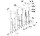
図1に示すように、平面視において、ワーク10は、駆動手段8によるワークの移動方向M及びその直交方向Nに複数行及び複数列に等間隔に並んで配置されており、即ち行列状に配置されている。このワーク行列状配置において、複数個のワーク10がワークの移動方向Mに一列に並んでなるワーク群を「ワーク行15」とし、複数個のワーク10がワークの移動方向Mの直交方向Nに一列に並んでなるワーク群を「ワーク列16」とする。本実施形態では、ワーク行15の全行数は12行であり、ワーク列16の全列数は12列であり、即ち12行×12列である。したがって、ワーク10の全個数は144個である。
As shown in FIG. 1, in a plan view, the
さらに、このワーク行列状配置では、ワーク行15におけるワーク10、10間のピッチP1と、ワーク列16におけるワーク10、10間のピッチP2とは、互いに等しく設定されており、望ましくはそれぞれワーク10の外径Uに対して1.5〜2.5倍の範囲に設定されるのが良い。
Furthermore, in this work matrix arrangement, the pitch P1 between the
上ノズル2及び下ノズル4は、平面視において、ワークの移動方向Mの直交方向Nに複数個交互に一列に等間隔に並んで配置されている。したがって、上ノズル2の配置位置と下ノズル4の配置位置とはワークの移動方向Mの直交方向Nにずれている。さらに、このように複数個の上ノズル2及び下ノズル4が交互に一列に並んでなるノズル群を「ノズル列6」とするとき、このノズル列6が更にワークの移動方向Mに等間隔に複数列配置されている。本実施形態では、ノズル列6の全列数は4列である。
A plurality of
平面視において、ノズル列6における上ノズル2及び下ノズル4間のピッチP4は、ワーク列16におけるワーク10、10間のピッチP2に対して1/2倍に設定されている。さらに、平面視において、各下ノズル4は、駆動手段8により移動されるワークの移動領域Zの内側に配置されており、詳述するとワークの移動領域Zの内側の幅方向中間位置に配置されている。一方、各上ノズル2は、ワークの移動領域Zの外側に配置されており、詳述するとワーク列16における互いに隣り合う2個のワーク10、10間の中間位置に配置されている。
In a plan view, the pitch P4 between the
また、複数列(本実施形態では4列)のノズル列6、6間のピッチP3は、ワーク行15におけるワーク10、10間のピッチP1に対して2〜11倍の範囲に設定されており、本実施形態ではP3はP1に対して3倍に設定されている。
The pitch P3 between the
各上ノズル2及び各下ノズル4は、各上ノズル2から噴射される上洗浄液3の噴射広がり方向Hと各下ノズル4から噴射される下洗浄液5の噴射広がり方向Jとが互いに平行になるように配置されている。すなわち、各上ノズル2及び各下ノズル4は、それぞれ上洗浄液3及び下洗浄液5を、上洗浄液3の噴射広がり方向Hと下洗浄液5の噴射広がり方向Jとが互いに平行になるように噴射するものである。ここで、上述したように、平面視において、上ノズル2の配置位置と下ノズル4の配置位置とがワークの移動方向Mの直交方向Nにずれていることから、各上ノズル2及び各下ノズル4からそれぞれ上洗浄液3及び下洗浄液5を噴射しても、上洗浄液3と下洗浄液5は互いに直接干渉することはなく、すなわち上洗浄液3と下洗浄液5は互いに直接衝突することはない。
In each
さらに、各上ノズル2及び各下ノズル4からそれぞれ上洗浄液3及び下洗浄液5が、上洗浄液3及び下洗浄液5の噴射広がり方向H、Jがともにワークの移動方向Mに対して斜め方向になるように噴射される。ワークの移動方向Mに対して上洗浄液3及び下洗浄液5の噴射広がり方向H、Jがなす角度α、αは、ともに望ましくは25〜80°の範囲に設定され、具体的にはα、αはともに例えば45°に設定される。
Further, the
各上ノズル2から噴射される上洗浄液3の単位時間当たりの噴射流量V1は、各下ノズル4から噴射される下洗浄液5の単位時間当たりの噴射流量V2よりも大きく設定されている(即ち、V1>V2)。望ましくはV1はV2に対して1.5〜3.0倍の範囲に設定されるのが良い。具体的には、V1は例えば4.5〜39L/minの範囲に設定され、V2は例えば3〜13L/minの範囲に設定される。
The injection flow rate V1 per unit time of the
図2に示すように、各上ノズル2から噴射される上洗浄液3の噴射広がり角度θ1は、各下ノズル4から噴射される下洗浄液5の噴射広がり角度θ2よりも小さく設定されている(即ち、θ1<θ2)。望ましくはθ2はθ1に対して1.2〜3.2倍の範囲に設定されるのが良い。具体的には、θ1は例えば25〜65°の範囲に設定され、θ2は例えば40〜80°の範囲に設定される。
As shown in FIG. 2, the spray spread angle θ1 of the
さらに、各下ノズル4とワーク10との間の鉛直方向の距離S2は、各上ノズル2とワーク10との間の鉛直方向の距離S1よりも短く設定されている(即ち、S2<S1)。望ましくはS1はS2に対して3〜7倍の範囲に設定されるのが良い。具体的には、S2は例えば10〜45mmの範囲に設定され、S1は例えば70〜150mmの範囲に設定される。
Further, the vertical distance S2 between each
このようにS2がS1よりも短く設定され、換言するとS1がS2よりも長く設定されることにより、図1に示すように、平面視において、ワーク配置位置における各上ノズル2から噴射される上洗浄液3の噴射広がり幅Wが、ワーク配置位置における各下ノズル4から噴射される下洗浄液5の噴射広がり幅Yよりも大きく設定されている。
As described above, S2 is set shorter than S1, in other words, S1 is set longer than S2, and as shown in FIG. The spray spread width W of the cleaning
詳述すると、上洗浄液3の噴射広がり幅Wにおけるワーク移動方向Mの直交方向Nの長さW1は、ワーク列16におけるワーク10、10間のピッチP2に対して2倍以上(更に詳述すると、2〜3倍の範囲に設定されている。これにより、上ノズル2から上洗浄液3を噴射した状態でワーク10を所定方向Mに移動させた場合に、上洗浄液3が、互いに隣り合う2つのワーク行15、15のうち一方のワーク行15の少なくとも1個(本実施形態では1又は2個)のワーク10の上面10a、外周面10b及び内周面10d(詳述すると内周面10dの上部)と、他方のワーク行15の少なくとも1個(本実施形態では1又は2個)のワーク10の上面10a、外周面10b及び内周面10d(詳述すると内周面10dの上部)とに当たるとともに、ワーク10の移動によって、ワーク10の上面10a全面、外周面10b全面及び内周面10d全面(詳述すると内周面10dの上部全面)が上洗浄液3で洗浄されるものとなされている。
More specifically, the length W1 in the orthogonal direction N of the workpiece movement direction M in the spray spreading width W of the
一方、下洗浄液5の噴射広がり幅Yにおけるワーク移動方向Mの直交方向Nの長さY1は、ワーク10の外径Uに対して等しいか又は長く設定されており、すなわちワーク列16におけるワーク10、10間のピッチP2に対して1倍以上(詳述すると、1〜1.8倍の範囲に設定されている。これにより、図2に示すように、下ノズル4から下洗浄液5を噴射した状態でワーク10を所定方向Mに移動させた場合に、下洗浄液5が、各ワーク行15における1個のワーク10の下面10c及び内周面10d(詳述すると内周面10dの下部)に当たるとともに、ワーク10の移動によって、ワーク10の下面10c全面及び内周面10d全面(詳述すると内周面10dの下部全面)が下洗浄液5で洗浄されるものとなされている。
On the other hand, the length Y1 in the orthogonal direction N of the workpiece movement direction M in the spray spreading width Y of the
駆動手段8によるワーク10の移動速度は、例えば8〜50mm/sの範囲である。ワーク10の移動距離は、ワーク行15におけるワーク10、10間のピッチP1の2倍の長さに対して等しいか又は長く設定され、望ましくはP1×2倍〜P1×3倍の範囲に設定されるのが良い。
The moving speed of the
さらに、ノズル列6における上ノズル2及び下ノズル4間のピッチP4と、ワークの移動方向Mに対して上洗浄液3及び下洗浄液5の噴射広がり方向H、Jがなす角度α、αとは、下洗浄液5がワーク10の下面10cに当たるときは、平面視において当該下洗浄液5を噴射した下ノズル4の両側に配置された2つの上ノズル2、2から噴射された上洗浄液3、3のうち少なくとも一方が必ず当該ワーク10の上面10a及び外周面10bからなる領域の少なくとも一部に当たるように設定されている。
Further, the pitches P4 between the
次に、本実施形態の洗浄装置1を用いたワーク10の洗浄方法について以下に説明する。
Next, a method for cleaning the
図3に二点鎖線で示すように、洗浄装置1のワーク支持部材7に複数個のワーク10をその軸Qが鉛直になるように支持させる。これにより、平面視において、複数個のワーク10をワークの移動方向M及びその直交方向Nに複数行及び複数列に並べた行列状に配置する。
As shown by a two-dot chain line in FIG. 3, a plurality of
次いで、洗浄装置1の各上ノズル2から上洗浄液3を下向きに扇形膜状に噴射するとともに、各下ノズル4から下洗浄液5を上向きに扇形膜状に噴射する。そしてこの状態を維持したままで、駆動手段8によって複数個のワーク10をワーク支持部材7を介して所定方向Mに一括して移動させる。
Next, the
すると、図1に示すように、上洗浄液3が、互いに隣り合う2つのワーク行15、15のうち一方のワーク行15の少なくとも1個(本実施形態では1又は2個)のワーク10の上面10a、外周面10b及び内周面10d(詳述すると内周面10dの上部)と他方のワーク行15の少なくとも1個(本実施形態では1又は2個)のワーク10の上面10a、外周面10b及び内周面10d(詳述すると内周面10dの上部)とに当たるとともに、ワーク10の移動によって、ワーク10の上面10a全面、外周面10b全面及び内周面10d全面(詳述すると内周面10dの上部全面)とが上洗浄液3で洗浄される。これと同時に、下洗浄液5が、各ワーク行15における1個のワーク10の下面10c及び内周面10d(詳述すると内周面10dの下部)に当たるとともに、ワーク10の移動によって、ワーク10の下面10c全面及び内周面10d(詳述すると内周面10dの下部全面)が下洗浄液5で洗浄される。以上の工程を「洗浄工程」という。
Then, as shown in FIG. 1, the
この洗浄工程では、下洗浄液5がワーク10の下面10cに当たるときは、平面視において当該下洗浄液5を噴射した下ノズル4の両側に配置された2つの上ノズル2、2から噴射された上洗浄液3、3のうち少なくとも一方が必ず当該ワーク10の上面10a及び外周面10bからなる領域の少なくとも一部に当たる。そのため、下洗浄液5のワーク下面10cへの当たり力(衝突力)によりワーク10が浮き上がる不具合を防止することができる。これにより、ワーク10の下面10cを確実に洗浄することができるし、更にワーク10の下面10cがワーク支持部材7のワーク載置部7aに衝突することによるワーク下面10cの傷付きを防止することができる。
In this cleaning process, when the
さらに、上ノズル2及び下ノズル4からそれぞれ上洗浄液3及び下洗浄液5を、上洗浄液3と下洗浄液5が互いに干渉しないように噴射することにより、上洗浄液3及び下洗浄液5の洗浄力をそれぞれ向上させることができる。
Further, the
さらに、上ノズル2から噴射される上洗浄液3の単位時間当たりの噴射流量V1が、下ノズル4から噴射される下洗浄液5の単位時間当たりの噴射流量V2よりも大きいことにより、ワーク10の浮き上がりを確実に防止することができる。
Further, since the injection flow rate V1 per unit time of the
さらに、ワーク10は筒状(詳述すると円筒状)であり且つその軸Qを鉛直にして配置されており、洗浄工程では、ワーク10の上面10a、外周面10b及び内周面10d(詳述すると内周面10dの上部)を上洗浄液3で洗浄するとともに、ワーク10の下面10c及び内周面10d(詳述すると内周面10dの下部)を下洗浄液5で洗浄することにより、ワーク10が小径な筒状(円筒状)であっても当該ワーク10の全面、即ちワーク10の上面10a、外周面10b、下面10c及び内周面10dを洗浄することができる。
Furthermore, the
さらに、上ノズル2及び下ノズル4はそれぞれフラットスプレーノズルから構成されており、洗浄工程では、上ノズル2及び下ノズル4からそれぞれ上洗浄液3及び下洗浄液5を扇形膜状に噴射している。そのため、上洗浄液3及び下洗浄液5のワーク10への当たり力が、フルコーンスプレーノズルから噴射される洗浄液のワーク10への当たり力よりも高くなっている。これにより、上洗浄液3及び下洗浄液5の洗浄力をそれぞれ更に向上させることができる。
Furthermore, the
さらに、上ノズル2及び下ノズル4からそれぞれ上洗浄液3及び下洗浄液5を、上洗浄液3の噴射広がり方向Hと下洗浄液5の噴射広がり方向Jとが互いに平行になるように噴射することにより、上洗浄液3と下洗浄液5との干渉を確実に防止できるし、更には、上洗浄液3と下洗浄液5を互いに近接して噴射することができ、これにより、ワーク10を効果的に洗浄することができるし、洗浄装置1の小型化を図ることができる。
Further, by spraying the
さらに、平面視において、ワーク10は、ワークの移動方向Mの直交方向Nに複数個並んで配置されるとともに、上ノズル2と下ノズル4は、ワーク10の移動方向Mの直交方向Nに複数個交互に並んで配置されているので、複数個のワーク10を一括して洗浄することができる。
Furthermore, in plan view, a plurality of
さらに、平面視において、上ノズル2は、ワークの移動領域Zの外側に配置される一方、下ノズル4は、ワークの移動領域Zの内側に配置されているので、上洗浄液3でワーク10の上面10a及び外周面10bを確実に洗浄することができるし、ワーク10が小径な筒状(円筒状)であっても当該ワーク10の下面10c及び内周面10dを下洗浄液5で確実に洗浄することができる。
Further, in the plan view, the
さらに、洗浄工程では、平面視において、上ノズル2及び下ノズル4からそれぞれ上洗浄液3及び下洗浄液5を、上洗浄液3及び下洗浄液5の噴射広がり方向H、Jがともにワークの移動方向Mに対して斜め方向になるように噴射するので、ワークの移動方向Mの直交方向Nに複数個並んでワーク10が配置された場合において、互いに隣り合う2個のワーク10、10を1つの上ノズル2から噴射された上洗浄液3で洗浄することが可能となる。これにより、ワーク10を効率良く洗浄することができる。
Further, in the cleaning process, the
さらに、平面視において、ワーク10は、ワークの移動方向M及びその直交方向Nに複数行及び複数列に複数個並んで配置されており、洗浄工程では、上洗浄液3が互いに隣り合う2つのワーク行15、15のうち一方のワーク行15の少なくとも1個のワーク10と他方のワーク行15の少なくとも1個のワーク10とに当たるように、上洗浄液3を噴射するので、より多くのワーク10を一括して洗浄することができ、もってワーク10を更に効率良く洗浄することができる。
Furthermore, in plan view, the
また、ワーク配置位置における上ノズル2から噴射される上洗浄液3の噴射広がり幅Wが、ワーク配置位置における下ノズル4から噴射される下洗浄液5の噴射広がり幅Yよりも大きいことにより、上ノズル2及び下ノズル4からそれぞれ上洗浄液3及び下洗浄液5を、下洗浄液5がワーク10の下面10cに当たるときは上洗浄液3が必ずワーク10の上面10a及び外周面10bからなる領域の少なくとも一部に当たるように噴射するという、上洗浄液3及び下洗浄液5の噴射状態を確実に実現することができる。
Further, since the spray spreading width W of the
さらに、下ノズル4とワーク10との間の鉛直方向の距離S2が、上ノズル2とワーク10との間の鉛直方向の距離S1よりも短いので、ワーク10の下面10cを確実に洗浄することができる。
Furthermore, since the vertical distance S2 between the
また、ワーク10は感光ドラム基体であるから、ワーク10としての感光ドラム基体を洗浄することができる。特に、ワーク10としての基体は、その軸を鉛直にして配置されることで基体の軸方向両端面がそれぞれ上面及び下面となるので、切粉が付着している基体の両端面を確実に洗浄し得て切粉を確実に除去することができる。
Further, since the
以上で本発明の一実施形態について説明したが、本発明は上記実施形態に限定されるものではなく、様々に変更可能である。 Although one embodiment of the present invention has been described above, the present invention is not limited to the above embodiment and can be variously modified.
例えば、上記実施形態では、上ノズル2及び下ノズル4の配置位置をそれぞれ固定した状態でワーク10を移動させる方式により、ワーク10の洗浄を行っているが、本発明では、その他に、ワーク10の配置位置を固定した状態で上ノズル2及び下ノズル4を移動させる方式により、ワーク10の洗浄を行うものであっても良い。
For example, in the above-described embodiment, the
もとより本発明では、ワーク10は感光ドラム基体以外のものであっても良い。
Of course, in the present invention, the
本発明は、感光ドラム基体等のワークの洗浄方法及び洗浄装置に利用可能である。 The present invention is applicable to a method and apparatus for cleaning a workpiece such as a photosensitive drum substrate.
1:洗浄装置
2:上スプレーノズル
3:上洗浄液
4:下スプレーノズル
5:下洗浄液
6:ノズル列
7:ワーク支持部材
10:ワーク
10a:上面
10b:外周面
10c:下面
10d:内周面
15:ワーク行
16:ワーク列
M:ワークの移動方向
N:ワークの移動方向の直交方向
Z:ワークの移動領域
S1:上ノズルとワークとの間の鉛直方向の距離
S2:下ノズルとワークとの間の鉛直方向の距離
1: Cleaning device 2: Upper spray nozzle 3: Upper cleaning liquid 4: Lower spray nozzle 5: Lower cleaning liquid 6: Nozzle row 7: Workpiece support member 10:
Claims (17)
前記上ノズル及び前記下ノズルはそれぞれフラットスプレーノズルから構成されており、
前記洗浄工程では、前記上ノズル及び前記下ノズルからそれぞれ前記上洗浄液及び前記下洗浄液を、下洗浄液がワークの下面に当たるときは上洗浄液が必ずワークの上面及び外周面からなる領域の少なくとも一部に当たるように且つ扇形膜状に噴射するものとし、
さらに、前記洗浄工程では、平面視において、前記上ノズル及び前記下ノズルからそれぞれ前記上洗浄液及び前記下洗浄液を、前記上洗浄液の噴射広がり方向と前記下洗浄液の噴射広がり方向とが互いに平行になるように噴射することを特徴とする洗浄方法。 In a state where the upper cleaning liquid is sprayed downward from the upper spray nozzle disposed on the upper side of the work and the lower cleaning liquid is ejected upward from the lower spray nozzle disposed on the lower side of the work, the work is directed to both the upper and lower nozzles. A cleaning step of cleaning at least the upper surface of the upper surface and the outer peripheral surface of the workpiece with the upper cleaning liquid and moving the lower surface of the workpiece with the lower cleaning liquid by moving in a relatively horizontal direction;
The upper nozzle and the lower nozzle are each composed of a flat spray nozzle,
In the cleaning step, the upper cleaning liquid and the lower cleaning liquid are applied from the upper nozzle and the lower nozzle, respectively, and when the lower cleaning liquid hits the lower surface of the work, the upper cleaning liquid always hits at least a part of the region formed by the upper surface and the outer peripheral surface of the work. And spray in the form of a fan-shaped film ,
Further, in the cleaning step, in the plan view, the upper cleaning liquid and the lower cleaning liquid are respectively supplied from the upper nozzle and the lower nozzle, and the jet spreading direction of the upper cleaning liquid and the jet spreading direction of the lower cleaning liquid are parallel to each other. The cleaning method is characterized by spraying .
前記洗浄工程では、前記上洗浄液が互いに隣り合う2つのワーク行のうち一方のワーク行の少なくとも1個のワークと他方のワーク行の少なくとも1個のワークとに当たるように、前記上洗浄液を噴射する請求項1記載の洗浄方法。 In plan view, the workpieces are arranged in a plurality of rows and a plurality of columns in the relative movement direction of the workpiece and the orthogonal direction thereof,
In the cleaning step, the upper cleaning liquid is sprayed so that the upper cleaning liquid hits at least one work in one work row and at least one work in the other work row among the two work rows adjacent to each other. The cleaning method according to claim 1 .
前記上ノズル及び前記下ノズルはそれぞれフラットスプレーノズルから構成されており、
前記洗浄工程では、前記上ノズル及び前記下ノズルからそれぞれ前記上洗浄液及び前記下洗浄液を、下洗浄液がワークの下面に当たるときは上洗浄液が必ずワークの上面及び外周面からなる領域の少なくとも一部に当たるように且つ扇形膜状に噴射するものとし、
平面視において、ワークは、前記ワークの相対移動方向の直交方向に複数個並んで配置されるとともに、
平面視において、前記上ノズルと前記下ノズルは、前記ワークの相対移動方向の直交方向に複数個交互に並んで配置されていることを特徴とする洗浄方法。 In a state where the upper cleaning liquid is sprayed downward from the upper spray nozzle disposed on the upper side of the work and the lower cleaning liquid is ejected upward from the lower spray nozzle disposed on the lower side of the work, the work is directed to both the upper and lower nozzles. A cleaning step of cleaning at least the upper surface of the upper surface and the outer peripheral surface of the workpiece with the upper cleaning liquid and moving the lower surface of the workpiece with the lower cleaning liquid by moving in a relatively horizontal direction;
The upper nozzle and the lower nozzle are each composed of a flat spray nozzle,
In the cleaning step, the upper cleaning liquid and the lower cleaning liquid are applied from the upper nozzle and the lower nozzle, respectively, and when the lower cleaning liquid hits the lower surface of the work, the upper cleaning liquid always hits at least a part of the region formed by the upper surface and the outer peripheral surface of the work. And spray in the form of a fan-shaped film ,
In plan view, a plurality of workpieces are arranged side by side in a direction orthogonal to the relative movement direction of the workpiece,
In the plan view, a plurality of the upper nozzles and the lower nozzles are alternately arranged in a direction orthogonal to the relative movement direction of the workpiece.
前記上ノズル及び前記下ノズルはそれぞれフラットスプレーノズルから構成されており、
前記洗浄工程では、前記上ノズル及び前記下ノズルからそれぞれ前記上洗浄液及び前記下洗浄液を、下洗浄液がワークの下面に当たるときは上洗浄液が必ずワークの上面及び外周面からなる領域の少なくとも一部に当たるように且つ扇形膜状に噴射するものとし、
平面視において、前記上ノズルは、前記ワークの相対移動領域の外側に配置される一方、前記下ノズルは、前記ワークの相対移動領域の内側に配置されていることを特徴とする洗浄方法。 In a state where the upper cleaning liquid is sprayed downward from the upper spray nozzle disposed on the upper side of the work and the lower cleaning liquid is ejected upward from the lower spray nozzle disposed on the lower side of the work, the work is directed to both the upper and lower nozzles. A cleaning step of cleaning at least the upper surface of the upper surface and the outer peripheral surface of the workpiece with the upper cleaning liquid and moving the lower surface of the workpiece with the lower cleaning liquid by moving in a relatively horizontal direction;
The upper nozzle and the lower nozzle are each composed of a flat spray nozzle,
In the cleaning step, the upper cleaning liquid and the lower cleaning liquid are applied from the upper nozzle and the lower nozzle, respectively, and when the lower cleaning liquid hits the lower surface of the work, the upper cleaning liquid always hits at least a part of the region formed by the upper surface and the outer peripheral surface of the work. And spray in the form of a fan-shaped film ,
In the plan view, the upper nozzle is disposed outside the relative movement area of the workpiece, while the lower nozzle is disposed inside the relative movement area of the workpiece.
前記洗浄工程では、前記上洗浄液が互いに隣り合う2つのワーク行のうち一方のワーク行の少なくとも1個のワークと他方のワーク行の少なくとも1個のワークとに当たるように、前記上洗浄液を噴射する請求項5記載の洗浄方法。 In plan view, the workpieces are arranged in a plurality of rows and a plurality of columns in the relative movement direction of the workpiece and the orthogonal direction thereof,
In the cleaning step, the upper cleaning liquid is sprayed so that the upper cleaning liquid hits at least one work in one work row and at least one work in the other work row among the two work rows adjacent to each other. The cleaning method according to claim 5 .
前記上ノズル及び前記下ノズルはそれぞれフラットスプレーノズルから構成されており、
前記洗浄工程では、前記上ノズル及び前記下ノズルからそれぞれ前記上洗浄液及び前記下洗浄液を、下洗浄液がワークの下面に当たるときは上洗浄液が必ずワークの上面及び外周面からなる領域の少なくとも一部に当たるように且つ扇形膜状に噴射するものとし、
さらに、前記洗浄工程では、平面視において、前記上ノズル及び前記下ノズルからそれぞれ前記上洗浄液及び前記下洗浄液を、上洗浄液及び下洗浄液の噴射広がり方向がともに前記ワークの相対移動方向に対して斜め方向になるように噴射することを特徴とする洗浄方法。 In a state where the upper cleaning liquid is sprayed downward from the upper spray nozzle disposed on the upper side of the work and the lower cleaning liquid is ejected upward from the lower spray nozzle disposed on the lower side of the work, the work is directed to both the upper and lower nozzles. A cleaning step of cleaning at least the upper surface of the upper surface and the outer peripheral surface of the workpiece with the upper cleaning liquid and moving the lower surface of the workpiece with the lower cleaning liquid by moving in a relatively horizontal direction;
The upper nozzle and the lower nozzle are each composed of a flat spray nozzle,
In the cleaning step, the upper cleaning liquid and the lower cleaning liquid are applied from the upper nozzle and the lower nozzle, respectively, and when the lower cleaning liquid hits the lower surface of the work, the upper cleaning liquid always hits at least a part of the region formed by the upper surface and the outer peripheral surface of the work. And spray in the form of a fan-shaped film ,
Further, in the cleaning step, in the plan view, the upper cleaning liquid and the lower cleaning liquid are respectively discharged from the upper nozzle and the lower nozzle, and the spray spreading directions of the upper cleaning liquid and the lower cleaning liquid are both oblique with respect to the relative movement direction of the workpiece. A cleaning method characterized by spraying in a direction.
前記洗浄工程では、前記上洗浄液が互いに隣り合う2つのワーク行のうち一方のワーク行の少なくとも1個のワークと他方のワーク行の少なくとも1個のワークとに当たるように、前記上洗浄液を噴射する請求項7記載の洗浄方法。 In plan view, the workpieces are arranged in a plurality of rows and a plurality of columns in the relative movement direction of the workpiece and the orthogonal direction thereof,
In the cleaning step, the upper cleaning liquid is sprayed so that the upper cleaning liquid hits at least one work in one work row and at least one work in the other work row among the two work rows adjacent to each other. The cleaning method according to claim 7 .
前記上ノズル及び前記下ノズルはそれぞれフラットスプレーノズルから構成されており、
前記洗浄工程では、前記上ノズル及び前記下ノズルからそれぞれ前記上洗浄液及び前記下洗浄液を、下洗浄液がワークの下面に当たるときは上洗浄液が必ずワークの上面及び外周面からなる領域の少なくとも一部に当たるように且つ扇形膜状に噴射するものとし、
平面視において、ワークは、前記ワークの相対移動方向及びその直交方向に複数行及び複数列に並んで配置されており、
さらに、前記洗浄工程では、前記上洗浄液が互いに隣り合う2つのワーク行のうち一方のワーク行の少なくとも1個のワークと他方のワーク行の少なくとも1個のワークとに当たるように、前記上洗浄液を噴射することを特徴とする洗浄方法。 In a state where the upper cleaning liquid is sprayed downward from the upper spray nozzle disposed on the upper side of the work and the lower cleaning liquid is ejected upward from the lower spray nozzle disposed on the lower side of the work, the work is directed to both the upper and lower nozzles. A cleaning step of cleaning at least the upper surface of the upper surface and the outer peripheral surface of the workpiece with the upper cleaning liquid and moving the lower surface of the workpiece with the lower cleaning liquid by moving in a relatively horizontal direction;
The upper nozzle and the lower nozzle are each composed of a flat spray nozzle,
In the cleaning step, the upper cleaning liquid and the lower cleaning liquid are applied from the upper nozzle and the lower nozzle, respectively, and when the lower cleaning liquid hits the lower surface of the work, the upper cleaning liquid always hits at least a part of the region formed by the upper surface and the outer peripheral surface of the work. And spray in the form of a fan-shaped film ,
In plan view, the workpieces are arranged in a plurality of rows and a plurality of columns in the relative movement direction of the workpiece and the orthogonal direction thereof,
Further, in the cleaning step, the upper cleaning liquid is applied so that the upper cleaning liquid hits at least one work in one work row and at least one work in the other work row among the two work rows adjacent to each other. A cleaning method characterized by spraying.
前記上ノズル及び前記下ノズルはそれぞれフラットスプレーノズルから構成されており、
前記洗浄工程では、前記上ノズル及び前記下ノズルからそれぞれ前記上洗浄液及び前記下洗浄液を、下洗浄液がワークの下面に当たるときは上洗浄液が必ずワークの上面及び外周面からなる領域の少なくとも一部に当たるように且つ扇形膜状に噴射するものとし、
ワーク配置位置における前記上ノズルから噴射される前記上洗浄液の噴射広がり幅が、ワーク配置位置における前記下ノズルから噴射される前記下洗浄液の噴射広がり幅よりも大きいことを特徴とする洗浄方法。 In a state where the upper cleaning liquid is sprayed downward from the upper spray nozzle disposed on the upper side of the work and the lower cleaning liquid is ejected upward from the lower spray nozzle disposed on the lower side of the work, the work is directed to both the upper and lower nozzles. A cleaning step of cleaning at least the upper surface of the upper surface and the outer peripheral surface of the workpiece with the upper cleaning liquid and moving the lower surface of the workpiece with the lower cleaning liquid by moving in a relatively horizontal direction;
The upper nozzle and the lower nozzle are each composed of a flat spray nozzle,
In the cleaning step, the upper cleaning liquid and the lower cleaning liquid are applied from the upper nozzle and the lower nozzle, respectively, and when the lower cleaning liquid hits the lower surface of the work, the upper cleaning liquid always hits at least a part of the region formed by the upper surface and the outer peripheral surface of the work. And spray in the form of a fan-shaped film ,
A cleaning method, wherein a spray spreading width of the upper cleaning liquid sprayed from the upper nozzle at a work placement position is larger than a spray spreading width of the lower cleaning liquid sprayed from the lower nozzle at a work placement position.
ワークの下側に配置されるとともに下洗浄液を上向きに噴射する下スプレーノズルと、
ワークを前記上下両ノズルに対して相対的に水平方向に移動させる駆動手段と、を備え、
前記上ノズル及び前記下ノズルからそれぞれ前記上洗浄液及び前記下洗浄液が噴射された状態で、前記駆動手段によってワークを相対移動させることにより、ワークの上面及び外周面のうち少なくとも上面を前記上洗浄液で洗浄するとともにワークの下面を前記下洗浄液で洗浄するように構成され、
前記上ノズル及び前記下ノズルはそれぞれフラットスプレーノズルから構成されており、
前記上ノズル及び前記下ノズルからそれぞれ前記上洗浄液及び前記下洗浄液が、下洗浄液がワークの下面に当たるときは上洗浄液が必ずワークの上面及び外周面からなる領域の少なくとも一部に当たるように且つ扇形膜状に噴射され、
さらに、平面視において、前記上ノズル及び前記下ノズルからそれぞれ前記上洗浄液及び前記下洗浄液が、前記上洗浄液の噴射広がり方向と前記下洗浄液の噴射広がり方向とが互いに平行になるように噴射されることを特徴とする洗浄装置。 An upper spray nozzle that is disposed on the upper side of the work and sprays the upper cleaning liquid downward;
A lower spray nozzle disposed below the workpiece and spraying a lower cleaning liquid upward;
Drive means for moving the workpiece in the horizontal direction relative to the upper and lower nozzles, and
In a state where the upper cleaning liquid and the lower cleaning liquid are respectively ejected from the upper nozzle and the lower nozzle, the work is relatively moved by the driving means, so that at least the upper surface and the outer peripheral surface of the work are covered with the upper cleaning liquid. It is configured to clean the lower surface of the workpiece with the lower cleaning liquid as well as cleaning,
The upper nozzle and the lower nozzle are each composed of a flat spray nozzle,
The upper nozzle and the upper cleaning liquid and the lower cleaning liquid from each of the lower nozzle, and the fan-shaped film to impinge on at least a part of the region composed of the upper surface and the outer peripheral surface of always the upper cleaning solution workpiece when the lower cleaning liquid hits the bottom surface of the workpiece is injected into the Jo,
Further, in a plan view, the upper cleaning liquid and the lower cleaning liquid are sprayed from the upper nozzle and the lower nozzle, respectively, so that the jet spreading direction of the upper cleaning liquid and the jet spreading direction of the lower cleaning liquid are parallel to each other. A cleaning apparatus characterized by that.
ワークの下側に配置されるとともに下洗浄液を上向きに噴射する下スプレーノズルと、
ワークを前記上下両ノズルに対して相対的に水平方向に移動させる駆動手段と、を備え、
前記上ノズル及び前記下ノズルからそれぞれ前記上洗浄液及び前記下洗浄液が噴射された状態で、前記駆動手段によってワークを相対移動させることにより、ワークの上面及び外周面のうち少なくとも上面を前記上洗浄液で洗浄するとともにワークの下面を前記下洗浄液で洗浄するように構成され、
前記上ノズル及び前記下ノズルはそれぞれフラットスプレーノズルから構成されており、
前記上ノズル及び前記下ノズルからそれぞれ前記上洗浄液及び前記下洗浄液が、下洗浄液がワークの下面に当たるときは上洗浄液が必ずワークの上面及び外周面からなる領域の少なくとも一部に当たるように且つ扇形膜状に噴射され、
平面視において、ワークは、前記ワークの相対移動方向の直交方向に複数個並んで配置されるとともに、
平面視において、前記上ノズルと前記下ノズルは、前記ワークの相対移動方向の直交方向に複数個交互に並んで配置されていることを特徴とする洗浄装置。 An upper spray nozzle that is disposed on the upper side of the work and sprays the upper cleaning liquid downward;
A lower spray nozzle disposed below the workpiece and spraying a lower cleaning liquid upward;
Drive means for moving the workpiece in the horizontal direction relative to the upper and lower nozzles, and
In a state where the upper cleaning liquid and the lower cleaning liquid are respectively ejected from the upper nozzle and the lower nozzle, the work is relatively moved by the driving means, so that at least the upper surface and the outer peripheral surface of the work are covered with the upper cleaning liquid. It is configured to clean the lower surface of the workpiece with the lower cleaning liquid as well as cleaning,
The upper nozzle and the lower nozzle are each composed of a flat spray nozzle,
The upper nozzle and the upper cleaning liquid and the lower cleaning liquid from each of the lower nozzle, and the fan-shaped film to impinge on at least a part of the region composed of the upper surface and the outer peripheral surface of always the upper cleaning solution workpiece when the lower cleaning liquid hits the bottom surface of the workpiece is injected into the Jo,
In plan view, a plurality of workpieces are arranged side by side in a direction orthogonal to the relative movement direction of the workpiece,
In the plan view, a plurality of the upper nozzles and the lower nozzles are alternately arranged in a direction orthogonal to the relative movement direction of the workpiece.
ワークの下側に配置されるとともに下洗浄液を上向きに噴射する下スプレーノズルと、
ワークを前記上下両ノズルに対して相対的に水平方向に移動させる駆動手段と、を備え、
前記上ノズル及び前記下ノズルからそれぞれ前記上洗浄液及び前記下洗浄液が噴射された状態で、前記駆動手段によってワークを相対移動させることにより、ワークの上面及び外周面のうち少なくとも上面を前記上洗浄液で洗浄するとともにワークの下面を前記下洗浄液で洗浄するように構成され、
前記上ノズル及び前記下ノズルはそれぞれフラットスプレーノズルから構成されており、
前記上ノズル及び前記下ノズルからそれぞれ前記上洗浄液及び前記下洗浄液が、下洗浄液がワークの下面に当たるときは上洗浄液が必ずワークの上面及び外周面からなる領域の少なくとも一部に当たるように且つ扇形膜状に噴射され、
平面視において、前記上ノズルは、前記ワークの相対移動領域の外側に配置される一方、前記下ノズルは、前記ワークの相対移動領域の内側に配置されていることを特徴とする洗浄装置。 An upper spray nozzle that is disposed on the upper side of the work and sprays the upper cleaning liquid downward;
A lower spray nozzle disposed below the workpiece and spraying a lower cleaning liquid upward;
Drive means for moving the workpiece in the horizontal direction relative to the upper and lower nozzles, and
In a state where the upper cleaning liquid and the lower cleaning liquid are respectively ejected from the upper nozzle and the lower nozzle, the work is relatively moved by the driving means, so that at least the upper surface and the outer peripheral surface of the work are covered with the upper cleaning liquid. It is configured to clean the lower surface of the workpiece with the lower cleaning liquid as well as cleaning,
The upper nozzle and the lower nozzle are each composed of a flat spray nozzle,
The upper nozzle and the upper cleaning liquid and the lower cleaning liquid from each of the lower nozzle, and the fan-shaped film to impinge on at least a part of the region composed of the upper surface and the outer peripheral surface of always the upper cleaning solution workpiece when the lower cleaning liquid hits the bottom surface of the workpiece is injected into the Jo,
In a plan view, the upper nozzle is disposed outside the relative movement area of the workpiece, while the lower nozzle is disposed inside the relative movement area of the workpiece.
ワークの下側に配置されるとともに下洗浄液を上向きに噴射する下スプレーノズルと、
ワークを前記上下両ノズルに対して相対的に水平方向に移動させる駆動手段と、を備え、
前記上ノズル及び前記下ノズルからそれぞれ前記上洗浄液及び前記下洗浄液が噴射された状態で、前記駆動手段によってワークを相対移動させることにより、ワークの上面及び外周面のうち少なくとも上面を前記上洗浄液で洗浄するとともにワークの下面を前記下洗浄液で洗浄するように構成され、
前記上ノズル及び前記下ノズルはそれぞれフラットスプレーノズルから構成されており、
前記上ノズル及び前記下ノズルからそれぞれ前記上洗浄液及び前記下洗浄液が、下洗浄液がワークの下面に当たるときは上洗浄液が必ずワークの上面及び外周面からなる領域の少なくとも一部に当たるように且つ扇形膜状に噴射され、
さらに、平面視において、前記上ノズル及び前記下ノズルからそれぞれ前記上洗浄液及び前記下洗浄液が、上洗浄液及び下洗浄液の噴射広がり方向がともに前記ワークの相対移動方向に対して斜め方向になるように噴射されることを特徴とする洗浄装置。 An upper spray nozzle that is disposed on the upper side of the work and sprays the upper cleaning liquid downward;
A lower spray nozzle disposed below the workpiece and spraying a lower cleaning liquid upward;
Drive means for moving the workpiece in the horizontal direction relative to the upper and lower nozzles, and
In a state where the upper cleaning liquid and the lower cleaning liquid are respectively ejected from the upper nozzle and the lower nozzle, the work is relatively moved by the driving means, so that at least the upper surface and the outer peripheral surface of the work are covered with the upper cleaning liquid. It is configured to clean the lower surface of the workpiece with the lower cleaning liquid as well as cleaning,
The upper nozzle and the lower nozzle are each composed of a flat spray nozzle,
The upper nozzle and the upper cleaning liquid and the lower cleaning liquid from each of the lower nozzle, and the fan-shaped film to impinge on at least a part of the region composed of the upper surface and the outer peripheral surface of always the upper cleaning solution workpiece when the lower cleaning liquid hits the bottom surface of the workpiece is injected into the Jo,
Further, in the plan view, the upper cleaning liquid and the lower cleaning liquid are respectively ejected from the upper nozzle and the lower nozzle so that the jet spreading directions of the upper cleaning liquid and the lower cleaning liquid are oblique to the relative movement direction of the workpiece. A cleaning device characterized by being sprayed.
ワークの下側に配置されるとともに下洗浄液を上向きに噴射する下スプレーノズルと、
ワークを前記上下両ノズルに対して相対的に水平方向に移動させる駆動手段と、を備え、
前記上ノズル及び前記下ノズルからそれぞれ前記上洗浄液及び前記下洗浄液が噴射された状態で、前記駆動手段によってワークを相対移動させることにより、ワークの上面及び外周面のうち少なくとも上面を前記上洗浄液で洗浄するとともにワークの下面を前記下洗浄液で洗浄するように構成され、
前記上ノズル及び前記下ノズルはそれぞれフラットスプレーノズルから構成されており、
前記上ノズル及び前記下ノズルからそれぞれ前記上洗浄液及び前記下洗浄液が、下洗浄液がワークの下面に当たるときは上洗浄液が必ずワークの上面及び外周面からなる領域の少なくとも一部に当たるように且つ扇形膜状に噴射され、
前記ワークは、前記ワークの相対移動方向及びその直交方向に複数行及び複数列に並んで配置されており、
さらに、前記上洗浄液が互いに隣り合う2つのワーク行のうち一方のワーク行の少なくとも1個のワークと他方のワーク行の少なくとも1個のワークとに当たるように、前記上洗浄液が噴射されることを特徴とする洗浄装置。 An upper spray nozzle that is disposed on the upper side of the work and sprays the upper cleaning liquid downward;
A lower spray nozzle disposed below the workpiece and spraying a lower cleaning liquid upward;
Drive means for moving the workpiece in the horizontal direction relative to the upper and lower nozzles, and
In a state where the upper cleaning liquid and the lower cleaning liquid are respectively ejected from the upper nozzle and the lower nozzle, the work is relatively moved by the driving means, so that at least the upper surface and the outer peripheral surface of the work are covered with the upper cleaning liquid. It is configured to clean the lower surface of the workpiece with the lower cleaning liquid as well as cleaning,
The upper nozzle and the lower nozzle are each composed of a flat spray nozzle,
The upper nozzle and the upper cleaning liquid and the lower cleaning liquid from each of the lower nozzle, and the fan-shaped film to impinge on at least a part of the region composed of the upper surface and the outer peripheral surface of always the upper cleaning solution workpiece when the lower cleaning liquid hits the bottom surface of the workpiece is injected into the Jo,
The workpiece is arranged in a plurality of rows and a plurality of columns in the relative movement direction of the workpiece and the orthogonal direction thereof,
Further, the upper cleaning liquid is sprayed such that the upper cleaning liquid hits at least one work in one work row and at least one work in the other work row among the two work rows adjacent to each other. Characteristic cleaning device.
ワークの下側に配置されるとともに下洗浄液を上向きに噴射する下スプレーノズルと、
ワークを前記上下両ノズルに対して相対的に水平方向に移動させる駆動手段と、を備え、
前記上ノズル及び前記下ノズルからそれぞれ前記上洗浄液及び前記下洗浄液が噴射された状態で、前記駆動手段によってワークを相対移動させることにより、ワークの上面及び外周面のうち少なくとも上面を前記上洗浄液で洗浄するとともにワークの下面を前記下洗浄液で洗浄するように構成され、
前記上ノズル及び前記下ノズルはそれぞれフラットスプレーノズルから構成されており、
前記上ノズル及び前記下ノズルからそれぞれ前記上洗浄液及び前記下洗浄液が、下洗浄液がワークの下面に当たるときは上洗浄液が必ずワークの上面及び外周面からなる領域の少なくとも一部に当たるように且つ扇形膜状に噴射され、
ワーク配置位置における前記上ノズルから噴射される前記上洗浄液の噴射広がり幅が、ワーク配置位置における前記下ノズルから噴射される前記下洗浄液の噴射広がり幅よりも大きいことを特徴とする洗浄装置。 An upper spray nozzle that is disposed on the upper side of the work and sprays the upper cleaning liquid downward;
A lower spray nozzle disposed below the workpiece and spraying a lower cleaning liquid upward;
Drive means for moving the workpiece in the horizontal direction relative to the upper and lower nozzles, and
In a state where the upper cleaning liquid and the lower cleaning liquid are respectively ejected from the upper nozzle and the lower nozzle, the work is relatively moved by the driving means, so that at least the upper surface and the outer peripheral surface of the work are covered with the upper cleaning liquid. It is configured to clean the lower surface of the workpiece with the lower cleaning liquid as well as cleaning,
The upper nozzle and the lower nozzle are each composed of a flat spray nozzle,
The upper nozzle and the upper cleaning liquid and the lower cleaning liquid from each of the lower nozzle, and the fan-shaped film to impinge on at least a part of the region composed of the upper surface and the outer peripheral surface of always the upper cleaning solution workpiece when the lower cleaning liquid hits the bottom surface of the workpiece is injected into the Jo,
The cleaning apparatus according to claim 1, wherein an ejection spread width of the upper cleaning liquid ejected from the upper nozzle at a work placement position is larger than an ejection spread width of the lower cleaning liquid ejected from the lower nozzle at a work placement position.
Priority Applications (4)
| Application Number | Priority Date | Filing Date | Title |
|---|---|---|---|
| JP2010118371A JP5490610B2 (en) | 2010-05-24 | 2010-05-24 | Cleaning method |
| CN201180025373.9A CN102905803B (en) | 2010-05-24 | 2011-05-17 | Cleaning method |
| US13/699,427 US20150053242A1 (en) | 2010-05-24 | 2011-05-17 | Cleaning method |
| PCT/JP2011/061312 WO2011148827A1 (en) | 2010-05-24 | 2011-05-17 | Cleaning method |
Applications Claiming Priority (1)
| Application Number | Priority Date | Filing Date | Title |
|---|---|---|---|
| JP2010118371A JP5490610B2 (en) | 2010-05-24 | 2010-05-24 | Cleaning method |
Publications (3)
| Publication Number | Publication Date |
|---|---|
| JP2011245364A JP2011245364A (en) | 2011-12-08 |
| JP2011245364A5 JP2011245364A5 (en) | 2012-12-27 |
| JP5490610B2 true JP5490610B2 (en) | 2014-05-14 |
Family
ID=45003818
Family Applications (1)
| Application Number | Title | Priority Date | Filing Date |
|---|---|---|---|
| JP2010118371A Active JP5490610B2 (en) | 2010-05-24 | 2010-05-24 | Cleaning method |
Country Status (4)
| Country | Link |
|---|---|
| US (1) | US20150053242A1 (en) |
| JP (1) | JP5490610B2 (en) |
| CN (1) | CN102905803B (en) |
| WO (1) | WO2011148827A1 (en) |
Families Citing this family (6)
| Publication number | Priority date | Publication date | Assignee | Title |
|---|---|---|---|---|
| JP5643556B2 (en) * | 2009-07-10 | 2014-12-17 | キヤノン株式会社 | A method for rinsing and cleaning a cylindrical substrate for an electrophotographic photoreceptor and a method for producing an electrophotographic photoreceptor. |
| CN103230891A (en) * | 2013-05-03 | 2013-08-07 | 山东瑞帆果蔬机械科技有限公司 | Cross-flow cleaning spray device |
| CN103941562A (en) * | 2014-05-09 | 2014-07-23 | 深圳市华星光电技术有限公司 | Developer |
| JP2017000913A (en) * | 2015-06-04 | 2017-01-05 | 日本電気硝子株式会社 | Method and apparatus for processing tube glass |
| JP6420778B2 (en) * | 2016-01-15 | 2018-11-07 | 株式会社スギノマシン | Excess thermal spray coating removal device, shield plate, and shield unit |
| GB2609028B (en) * | 2021-07-19 | 2024-03-27 | Tiny Air Ltd | Apparatus for pre-cleaning of surgical instruments |
Family Cites Families (11)
| Publication number | Priority date | Publication date | Assignee | Title |
|---|---|---|---|---|
| US3262460A (en) * | 1964-02-17 | 1966-07-26 | Cincinnati Cleaning And Finish | Conveyor type cleaning device for fragile containers and the like |
| US4092991A (en) * | 1975-10-16 | 1978-06-06 | Metalwash Machinery Corporation | Cleaning machine |
| JPH0444222Y2 (en) * | 1987-01-08 | 1992-10-19 | ||
| JP2754300B2 (en) * | 1991-12-06 | 1998-05-20 | 大和製罐株式会社 | DI can surface treatment method and apparatus |
| US5564448A (en) * | 1994-12-14 | 1996-10-15 | Eagle-Picher Industries, Inc. | Container washing apparatus and system |
| US5660196A (en) * | 1995-12-20 | 1997-08-26 | Oven Systems, Inc. | Quick disconnect riser pipe assembly for can washer |
| TW436332B (en) * | 1996-08-19 | 2001-05-28 | Siemens Ag | Process and equipment for cleaning of contaminated object |
| US6269823B1 (en) * | 1998-05-04 | 2001-08-07 | Eagle-Picher Industries, Inc. | Can washing apparatus with plastic risers |
| EP0983730A3 (en) * | 1998-09-03 | 2001-02-21 | Ryubi Company Ltd. | A food washing apparatus |
| JP4150195B2 (en) * | 2002-03-08 | 2008-09-17 | 古河スカイ株式会社 | Method for producing aluminum photosensitive drum substrate |
| JP2008093546A (en) * | 2006-10-10 | 2008-04-24 | Kn Lab Analysis:Kk | Tunnel type washing apparatus |
-
2010
- 2010-05-24 JP JP2010118371A patent/JP5490610B2/en active Active
-
2011
- 2011-05-17 CN CN201180025373.9A patent/CN102905803B/en not_active Expired - Fee Related
- 2011-05-17 US US13/699,427 patent/US20150053242A1/en not_active Abandoned
- 2011-05-17 WO PCT/JP2011/061312 patent/WO2011148827A1/en active Application Filing
Also Published As
| Publication number | Publication date |
|---|---|
| CN102905803B (en) | 2015-07-22 |
| CN102905803A (en) | 2013-01-30 |
| JP2011245364A (en) | 2011-12-08 |
| WO2011148827A1 (en) | 2011-12-01 |
| US20150053242A1 (en) | 2015-02-26 |
Similar Documents
| Publication | Publication Date | Title |
|---|---|---|
| JP5490610B2 (en) | Cleaning method | |
| JP6093569B2 (en) | Substrate cleaning device | |
| JP4936146B2 (en) | Substrate processing apparatus and substrate processing apparatus cleaning method using the same | |
| JP2013026381A (en) | Substrate processing apparatus and substrate processing method | |
| WO2019163651A1 (en) | Substrate cleaning apparatus and substrate cleaning method | |
| JP6233569B2 (en) | Wafer cleaning apparatus and wafer cleaning method | |
| JP4109175B2 (en) | Semiconductor manufacturing equipment | |
| JP5588768B2 (en) | Shock absorber cleaning device, cleaning method and manufacturing method | |
| JP2007252729A (en) | Basket and method for washing dishes | |
| JP2010274245A (en) | Washing apparatus, drying apparatus, and washing system | |
| JP2006000011A (en) | Continuous washing machine for root vegetables such as japanese radish | |
| KR101910968B1 (en) | Washing Device For Engine Cylinder Block Using Robot Arm | |
| JPH08332461A (en) | Method of cleaning in air and device therefor | |
| JP4256913B1 (en) | Dishwashing apparatus and dishwashing method | |
| JP2009525853A (en) | Cleaning assembly | |
| JP4556224B2 (en) | Cleaning method | |
| JP2012135706A (en) | Apparatus for washing inside of container | |
| JP2006297207A (en) | Washing device for substrate | |
| JPH06151398A (en) | Wafer cleaning equipment | |
| JP3226900U (en) | Cleaning equipment | |
| JP6966917B2 (en) | Board processing method and board processing equipment | |
| JP3391576B2 (en) | Degreasing equipment for processed sheet metal products | |
| JP2010051947A (en) | Method and apparatus for rinsing holes/capped-holes of small diameters in article surface | |
| JP2007125531A (en) | Washing apparatus | |
| JP2010063804A (en) | Dishwasher |
Legal Events
| Date | Code | Title | Description |
|---|---|---|---|
| A521 | Request for written amendment filed |
Free format text: JAPANESE INTERMEDIATE CODE: A523 Effective date: 20121114 |
|
| A621 | Written request for application examination |
Free format text: JAPANESE INTERMEDIATE CODE: A621 Effective date: 20130204 |
|
| A131 | Notification of reasons for refusal |
Free format text: JAPANESE INTERMEDIATE CODE: A131 Effective date: 20130903 |
|
| A521 | Request for written amendment filed |
Free format text: JAPANESE INTERMEDIATE CODE: A523 Effective date: 20131022 |
|
| TRDD | Decision of grant or rejection written | ||
| A01 | Written decision to grant a patent or to grant a registration (utility model) |
Free format text: JAPANESE INTERMEDIATE CODE: A01 Effective date: 20140204 |
|
| A61 | First payment of annual fees (during grant procedure) |
Free format text: JAPANESE INTERMEDIATE CODE: A61 Effective date: 20140226 |
|
| R150 | Certificate of patent or registration of utility model |
Ref document number: 5490610 Country of ref document: JP Free format text: JAPANESE INTERMEDIATE CODE: R150 |
|
| RD02 | Notification of acceptance of power of attorney |
Free format text: JAPANESE INTERMEDIATE CODE: R3D02 |
|
| S802 | Written request for registration of partial abandonment of right |
Free format text: JAPANESE INTERMEDIATE CODE: R311802 |
|
| R350 | Written notification of registration of transfer |
Free format text: JAPANESE INTERMEDIATE CODE: R350 |
|
| S111 | Request for change of ownership or part of ownership |
Free format text: JAPANESE INTERMEDIATE CODE: R313111 |
|
| R350 | Written notification of registration of transfer |
Free format text: JAPANESE INTERMEDIATE CODE: R350 |
|
| S531 | Written request for registration of change of domicile |
Free format text: JAPANESE INTERMEDIATE CODE: R313531 |
|
| R350 | Written notification of registration of transfer |
Free format text: JAPANESE INTERMEDIATE CODE: R350 |