JP5489809B2 - Image processing apparatus and image processing apparatus control method - Google Patents
Image processing apparatus and image processing apparatus control method Download PDFInfo
- Publication number
- JP5489809B2 JP5489809B2 JP2010069926A JP2010069926A JP5489809B2 JP 5489809 B2 JP5489809 B2 JP 5489809B2 JP 2010069926 A JP2010069926 A JP 2010069926A JP 2010069926 A JP2010069926 A JP 2010069926A JP 5489809 B2 JP5489809 B2 JP 5489809B2
- Authority
- JP
- Japan
- Prior art keywords
- image
- interpolation
- shift amount
- line
- processing apparatus
- Prior art date
- Legal status (The legal status is an assumption and is not a legal conclusion. Google has not performed a legal analysis and makes no representation as to the accuracy of the status listed.)
- Expired - Fee Related
Links
Images


Landscapes
- Testing, Inspecting, Measuring Of Stereoscopic Televisions And Televisions (AREA)
Description
本発明は、画像処理装置および画像処理装置の制御方法に関する。 The present invention relates to an image processing apparatus and a control method for the image processing apparatus.
従来、インタレース映像をプログレッシブ映像へ変換する技術は走査線補間技術として知られている。また、特許文献1には、立体映像を構成する2つの映像(インタレース映像;右目用映像と左目用映像)からプログレッシブ映像を生成する技術が開示されている。具体的には、特許文献1に開示の技術では、右目用映像と左目用映像とは互いに相補的な関係にある。そして、右目用映像の補間ライン(プログレッシブ映像を生成するために右目用映像に対して生成されるライン)の上下ラインと、左目用映像の上記補間ラインに相当するラインの映像信号を用いて、該補間ラインを生成する。
Conventionally, a technique for converting interlaced video to progressive video is known as a scanning line interpolation technique.
立体映像において、右目用映像と左目用映像とは非常に類似している(相関性が高い)が、それらの映像間には物体の奥行きに応じた視差が存在する。
上述した走査線補間技術はインタレース方式の右目用映像と左目用映像のそれぞれに対して適用可能であるが、それらの映像間の相関性を有効に利用することはできない。そのため、上述した走査線補間技術では高画質なプログレッシブ映像を生成することができない(画像のライン間を精度良く補間することができない)。
また、右目用映像と左目用映像とが互いに相補的な関係にあるとは限らない。右目用映像と左目用映像とが互いに相補的な関係にあったとしても、右目用映像の補間ラインに相当する左目用映像のラインの映像が必ずしも補間ラインの位置に対応する映像とは限らない。そのため、特許文献1の技術では、高画質なプログレッシブ映像を生成できないことや、プログレッシブ映像自体を生成できないことがある。
In the stereoscopic video, the right-eye video and the left-eye video are very similar (highly correlated), but there is a parallax corresponding to the depth of the object between the videos.
The scanning line interpolation technique described above can be applied to each of the interlaced right-eye video and left-eye video, but the correlation between these videos cannot be used effectively. For this reason, the above-described scanning line interpolation technique cannot generate a high-quality progressive video (it cannot accurately interpolate between lines of an image).
Also, the right-eye video and the left-eye video are not necessarily complementary to each other. Even if the right-eye video and the left-eye video are complementary to each other, the video of the left-eye video line corresponding to the interpolation line of the right-eye video is not necessarily the video corresponding to the position of the interpolation line. . For this reason, the technique of
本発明は、画像のライン間を精度良く補間することのできる画像処理装置および画像処理装置の制御方法を提供することを目的とする。 An object of the present invention is to provide an image processing apparatus and an image processing apparatus control method capable of accurately interpolating between lines of an image.
本発明の画像処理装置は、同一対象を異なる視点から撮影した第1画像と第2画像を用いて、前記第1画像のライン間を補間する画像処理装置であって、前記第1画像と前記第2画像を比較し、それらの画像間の垂直方向のずれ量を算出する算出手段と、前記ずれ量が誤りであるか否かを判定する判定手段と、前記ずれ量と前記判定手段の判定結果に基づいて、前記第1画像のライン間に補間ラインを生成する生成手段と、を有し、前記生成手段は、前記ずれ量が誤りではないと判定された場合、補間ラインの生成位置に対し、前記第2画像において該生成位置から前記ずれ量の分だけずれた位置に存在するラインを用いて補間ラインを生成する2画像間補間処理により補間画素を生成し、前記ずれ量が誤りであると判定された場合、フィールド内補間処理により補間画素を生成することを特徴とする。 An image processing apparatus of the present invention is an image processing apparatus that interpolates between lines of the first image using a first image and a second image obtained by photographing the same object from different viewpoints, and the first image and the second image A calculating means for comparing the second images and calculating a vertical shift amount between the images ; a determination means for determining whether or not the shift amount is an error; and a determination between the shift amount and the determination means Generating means for generating an interpolation line between the lines of the first image based on the result , and if the deviation is determined not to be an error , the generating means determines the interpolation line generation position. On the other hand, an interpolation pixel is generated by an inter-image interpolation process that generates an interpolation line using a line existing at a position shifted by the shift amount from the generation position in the second image, and the shift amount is incorrect. If it is determined that there is a fee, And generating an interpolation pixel by de interpolation process.
本発明の画像処理装置の制御方法は、同一対象を異なる視点から撮影した第1画像と第2画像を用いて、前記第1画像のライン間を補間する画像処理装置の制御方法であって、前記第1画像と前記第2画像を比較し、それらの画像間の垂直方向のずれ量を算出する算出ステップと、前記ずれ量が誤りであるか否かを判定する判定ステップと、前記ずれ量と前記判定ステップの判定結果に基づいて、前記第1画像のライン間に補間ラインを生成する生成ステップと、を有し、前記生成ステップでは、前記ずれ量が誤りではないと判定された場合、補間ラインの生成位置に対し、前記第2画像において該生成位置から前記ずれ
量の分だけずれた位置に存在するラインを用いて補間ラインを生成する2画像間補間処理により補間画素を生成し、前記ずれ量が誤りであると判定された場合、フィールド内補間処理により補間画素を生成することを特徴とする。
A control method for an image processing apparatus according to the present invention is a control method for an image processing apparatus that interpolates between lines of the first image using a first image and a second image obtained by photographing the same object from different viewpoints, A calculating step for comparing the first image with the second image and calculating a vertical shift amount between the images ; a determination step for determining whether the shift amount is an error; and the shift amount And a generation step of generating an interpolation line between the lines of the first image based on the determination result of the determination step, and in the generation step, when it is determined that the shift amount is not an error, Generating an interpolation pixel by an inter-image interpolation process for generating an interpolation line using a line existing at a position shifted from the generation position in the second image by the shift amount with respect to a generation position of the interpolation line ; Said If the amount is is judged to be false, and generates an interpolation pixel by intra-field interpolation process.
本発明によれば、画像のライン間を精度良く補間することができる。 According to the present invention, it is possible to accurately interpolate between lines of an image.
以下、本実施形態に係る画像処理装置及びその制御方法について説明する。本実施形態に係る画像処理装置は、同一対象を異なる視点から撮影した第1画像と第2画像を用いて、第1画像のライン間を補間する。 Hereinafter, an image processing apparatus and a control method thereof according to the present embodiment will be described. The image processing apparatus according to the present embodiment interpolates between the lines of the first image using the first image and the second image obtained by photographing the same object from different viewpoints.
<実施例1>
(構成)
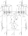
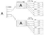
図1に本実施例に係る立体映像表示システムの構成を示す。
再生機1は光ディスクや磁気ディスクなどに記録された映像を再生する再生装置等を備える。再生機1は、同一対象を異なる視点から撮影した2つの映像(左入力映像(左目用の映像)と右入力映像(右目用の映像))から成る立体映像を再生し、左入力画像(信号)S1と右入力画像(信号)S2を出力する。左入力画像S1(第1画像)と右入力画像S2(第2画像)は、それぞれ、インタレース映像である左入力映像、右入力映像の1つのフィールドである。
IP変換部2は本実施例に係る画像処理装置である。IP変換部2は、左入力映像と右入力映像をそれぞれプログレッシブ映像に変換する。具体的には、左入力画像S1のライン間に補間ラインを生成することにより、左入力画像S1を左出力画像S15に変換する。右入力画像S2も同様に右出力画像S25に変換する。
立体表示機3は、左出力画像S15と右出力画像S25を取得して、立体映像を表示する。
<Example 1>
(Constitution)
FIG. 1 shows a configuration of a stereoscopic video display system according to the present embodiment.
The
The
The
次に、IP変換部2の構成を図2に示す。
左動き検出部11は、左入力画像S1の動きを検出する(動き検出手段)。具体的には、左入力画像S1(左注目フィールド)の前後のフィールドを用いて左入力画像S1にお
ける補間画素(補間ラインを構成する画素)の生成位置毎の動きの有無を検出する。そして、検出結果として左動き検出信号S11を出力する。
Next, the configuration of the
The
左フィールド内補間画像生成部12、左フィールド間補間画像生成部13、左右間補間画像生成部14、及び、左画素選択部15は、本発明の生成手段を構成する。
左フィールド内補間画像生成部12は、左入力画像S1に対し、フィールド内補間処理を実行する。具体的には、左入力画像S1における補間ラインの生成位置の上下のラインから補間ラインを生成し、生成した補間ラインで構成される左フィールド内補間画像S12を出力する。
左フィールド間補間画像生成部13は、左入力画像S1に対し、フィールド間補間処理を実行する。具体的には、左入力画像S1の前後のフィールドから左入力画像S1の補間ラインを生成し、生成した補間ラインで構成される左フィールド間補間画像S13を出力する。
左右間補間画像生成部14は、後述する左視差S41と上下オフセットS43を参照して、左入力画像S1と右入力画像S2から左入力画像S1の補間ラインを生成し、生成した補間ラインで構成される左右間補間画像S14を出力する。
左画素選択部15は、画素位置毎に、左動き検出信号S11と左視差S41に応じて、左入力画像S1、左フィールド内補間画像S12、左フィールド間補間画像S13、左右間補間画像S14のいずれかの画素を選択する。それにより、左出力画像S15を生成し出力する。
The left-field interpolated
The left intra-field
The inter-left-field interpolated
The left-right interpolated
For each pixel position, the left
右動き検出部21は、右入力画像S2(右注目フィールド)の前後のフィールドを用いて右入力画像S2における補間画素の生成位置毎の動きの有無を検出する。そして、検出結果として右動き検出信号S21を出力する。
The right
右フィールド内補間画像生成部22は、右入力画像S2における補間ラインの生成位置の上下のラインから補間ラインを生成し、生成した補間ラインで構成される右フィールド内補間画像S22を出力する。
右フィールド間補間画像生成部23は、右入力画像S2の前後のフィールドから右入力画像S2の補間ラインを生成し、生成した補間ラインで構成される右フィールド間補間画像S23を出力する。
右左間補間画像生成部24は、後述する右視差S42と上下オフセットS43を参照して、左入力画像S1と右入力画像S2から右入力画像S2の補間ラインを生成し、生成した補間ラインで構成される右左間補間画像S24を出力する。
右画素選択部25は、右動き検出信号S21と右視差S42に応じて、右入力画像S2、右フィールド内補間画像S22、右フィールド間補間画像S23、右左間補間画像S24のいずれかの画素を選択して右出力画像S25を出力する。
The inter-right field interpolated
The inter-right field interpolated
The right / left interpolated
The right
左右比較部30とオフセット検出部40は、本発明の算出手段を構成する。
左右比較部30は左入力画像S1と右入力画像S2を比較し、比較結果として左右ベクトルS31と右左ベクトルS32を出力する。本実施例では、左右比較部30は、左入力画像S1を複数の分割領域(ブロック)に分割し、分割領域毎に左右ベクトルS31を検出する。また、左入力画像S1と同様に右入力画像S2を複数の分割領域に分割し、分割領域毎に右左ベクトルS32を検出する。
オフセット検出部40は左右ベクトルS31と右左ベクトルS32を解析して左右画像間の垂直方向のずれ量を算出し、上下オフセットS43、左視差S41、右視差S42を出力する。
The left /
The left /
The offset
(動き検出方法)
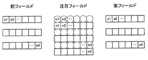
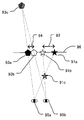
次に、左動き検出部11における動き検出方法の具体例を説明する。動き検出方法の概
念図を図3に示す。図3において、n1,n2,・・・,nXは左入力画像S1(左注目フィールド)の画素である。a1,a2,・・・,aXは左入力画像S1の1つ後のフィールドの画素である。b1,b2,・・・,bXは左入力画像S1の1つ前のフィールドの画素である。m1は、画素a1,b1の位置と等しい左入力画像S1内の位置(補間画素の生成位置)に対する動き情報である。動き情報m1は以下のように算出される(eは所定の閾値)。
|a1−b1|≦eであれば、m1=0(動きなし)
|a1−b1|>eであれば、m1=1(動きあり)
画素a2,・・・aX(画素b2,・・・,bX)の位置と等しい左注目フィールド内の各位置に対する動き情報m2,・・・,mXも同様に算出される。そして、それらの算出結果が左動き検出信号S11として出力される。
右動き検出部21における動き検出方法も同様である。
(Motion detection method)
Next, a specific example of a motion detection method in the left
If | a1-b1 | ≦ e, m1 = 0 (no motion)
If | a1-b1 |> e, m1 = 1 (with motion)
Motion information m2,..., MX for each position in the left field of interest equal to the position of the pixels a2,... AX (pixels b2,..., BX) is calculated in the same manner. Then, those calculation results are output as the left motion detection signal S11.
The motion detection method in the
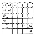
(フィールド内補間画像の生成方法)
次に、左フィールド内補間画像生成部12における左フィールド内補間画像の生成方法の具体例を説明する。生成方法の概念図を図4に示す。c1,c2,・・・,cXは補間により生成すべき画素(補間画素)である。左フィールド内補間画像生成部12は、上下に隣接する画素の平均値を補間画素の値とする。ただし、左補間画素の生成位置が最上位ラインもしくは最下位ライン上の位置のように上側もしくは下側に画素が存在しない位置である場合には、存在する一方の画素の値をそのまま補間画素の値とする。すなわち、図4の場合には、
c1=n1
cK=(n1+nK)/2
となる。全ての補間画素の値を算出することにより、それら補間画素から成る左フィールド内補間画像S12が生成される。
右フィールド内補間画像生成部22における右フィールド内補間画像の生成方法も同様である。
(Generation method of intra-field interpolation image)
Next, a specific example of a method for generating an inter-left field interpolated image in the inter-left field interpolated
c1 = n1
cK = (n1 + nK) / 2
It becomes. By calculating the values of all the interpolated pixels, a left-field interpolated image S12 composed of these interpolated pixels is generated.
The method for generating the inter-right field interpolated image in the inter-right field interpolated
(フィールド間補間画像の生成方法)
次に、左フィールド間補間画像生成部13における左フィールド間補間画像の生成方法の具体例を説明する。生成方法の概念図を図5に示す。d1,d2,・・・,dXは補間画素である。左フィールド間補間画像生成部13は、補間画素の値を以下のように算出する。
d1=(a1+b1)/2
補間画素d2,・・・,dXの値も同様に算出することにより、それら補間画素から成る左フィールド間補間画像S13が生成される。
右フィールド間補間画像生成部23における右フィールド間補間画像の生成方法も同様である。
(Generation method of inter-field interpolation image)
Next, a specific example of a method for generating an inter-left field interpolated image in the inter-left field interpolated
d1 = (a1 + b1) / 2
By calculating the values of the interpolated pixels d2,..., DX in the same manner, an inter-left-field interpolated image S13 composed of these interpolated pixels is generated.
The method for generating the inter-right field interpolated image in the inter-right field interpolated
(比較方法)
次に、左右比較部30における左入力画像と右入力画像の比較方法の具体例を説明する。左右比較部30の構成図を図6に示す。
左画像蓄積部111は、左入力画像S1を不図示のフレームメモリに蓄積する。また、左注目ブロック読出しアドレスS1110に応じて左注目ブロック画素S1111をフレームメモリから読み出して出力する。左探索ブロック読出しアドレスS1112に応じて左探索ブロック画素S1113をフレームメモリから読み出して出力する。
左注目ブロック抽出部112は、注目ブロック領域S130に基づいて左注目ブロックを順に選択し、選択したブロックの左注目ブロック読出しアドレスS1110を生成する。そして、左画像蓄積部111から左注目ブロック画素S1111を読み出し、左注目ブロックS112を出力する。
左右ブロック比較部113は、左注目ブロックS112と右探索ブロックS124を比較して左右ブロック一致度S113を出力する。一致度の算出方法の詳細は後述する。
左探索ブロック抽出部114は、左探索ベクトルS131に応じて左探索ブロック読出しアドレスS1112を生成する。そして、左画像蓄積部111から左探索ブロック画素S1113を読み出し、左探索ブロックS114を出力する。
左ベクトル選択部115は、各右探索ベクトルS132の左右ブロック一致度S113を検査し、最も一致度の高かった右探索ベクトルを左右ベクトルS31として出力する。
(Comparison method)
Next, a specific example of a method for comparing the left input image and the right input image in the left /
The left
The left attention
The left / right
The left search
The left
右画像蓄積部121は、右入力画像S2を不図示のフレームメモリに蓄積する。また、右注目ブロック読出しアドレスS1210に応じて右注目ブロック画素S1211をフレームメモリから読み出して出力する。右探索ブロック読出しアドレスS1212に応じて右探索ブロック画素S1213をフレームメモリから読み出して出力する。
右注目ブロック抽出部122は、注目ブロック領域S130に基づいて右注目ブロックを順に選択し、選択したブロックの右注目ブロック読出しアドレスS1210を生成する。そして、右画像蓄積部121から右注目ブロック画素S1211を読み出し、右注目ブロックS122を出力する。
右左ブロック比較部123は、右注目ブロックS122と左探索ブロックS114を比較して右左ブロック一致度S123を出力する。一致度の算出方法の詳細は後述する。
右探索ブロック抽出部124は、右探索ベクトルS132に応じて右探索ブロック読出しアドレスS1212を生成する。そして、右画像蓄積部121から右探索ブロック画素S1213を読み出し、右探索ブロックS124を出力する。
右ベクトル選択部125は、各左探索ベクトルS131の右左ブロック一致度S123を検査し、最も一致度の高かった左探索ベクトルを右左ベクトルS32として出力する。
The right
The right attention
The right / left
The right search
The right
ベクトル発生部130は、注目ブロック領域S130、左探索ベクトルS131、右探索ベクトルS132を順に発生して出力する。発生方法の詳細は後述する。
The
また、左右比較部30は不図示の制御部によって各部の動作および信号の流れが制御される。左右比較部30における処理(左右比較処理)の流れの一例を示すフローチャートを図7に示す。
ステップP301では画像の蓄積が行われる。左入力画像S1は左画像蓄積部111、右入力画像S2は右画像蓄積部121によりフレームメモリへ蓄積される。なお、フレームメモリは左画像蓄積部111と右画像蓄積部121とで個別に設けられていてもよいし、左画像蓄積部111と右画像蓄積部121とで共通のフレームメモリであってもよい。
In the left /
In step P301, image accumulation is performed. The left input image S1 is stored in the frame memory by the left
ステップP302では注目ブロック領域S130の選択を行う。注目ブロック領域の選択の概念図を図8に示す。IP変換部2で扱う全画像領域81を複数のブロック領域に分割し、各ブロック領域を順に注目ブロック領域82(注目ブロック領域S130)として選択する。本実施例ではブロック領域のサイズを8×8画素とする。すなわち、注目ブロック領域(注目するブロックの領域)として最初に対角座標(0,0),(7,7)の領域が選択され、次のステップP303へ移る。そして、制御ループが戻って次に注目ブロック領域を選択するときには、対角座標(8,0),(15,7)の領域が選択される。同様に順に選択を続け
、全画像領域81に右端に達したら、次に下の段、すなわち対角座標(0,8),(7,15)の領
域が選択される。以下同様にして順に全画像領域81の全ての領域が選択される。
In step P302, the target block area S130 is selected. FIG. 8 shows a conceptual diagram of selection of a target block area. The
ステップP303では注目ブロックの抽出を行う。左注目ブロック抽出部112は、左入力画像S1の画素のうち、選択された注目ブロック領域S130内の画素(左注目ブロック画素S1111)を読出す左注目ブロック読出しアドレスS1110を生成する。左画像蓄積部111は、左注目ブロック読出しアドレスS1110に従い、左注目ブロック画素S1111をフレームメモリから読み出す。左注目ブロック抽出部112は、読み出
された画素を再構成して左注目ブロックS112(左入力画像S1のうち、選択された注目ブロック領域の画像)を生成する。
右注目ブロック抽出部122においても同様の動作が行われる。
ステップP304では探索ベクトルの発生を行う。探索ベクトルと探索ブロックの概念図を図9に示す。探索領域83は左探索ベクトルS131、右探索ベクトルS132をそれぞれ独立に設定する。
In step P303, the target block is extracted. The left target
The same operation is performed in the right target
In step P304, a search vector is generated. FIG. 9 shows a conceptual diagram of search vectors and search blocks. The
以下、ステップP304の処理について具体的に説明する。
立体映像の左右視差(左入力画像S1と右入力画像S2の水平方向の視差)は、観察者の左右の目が寄る方向(画面より手前に飛び出す方向)に大きくすることは可能であるが、その逆方向の視差を大きくすることはできない。それは、人間の目が一般的に並行よりも離れた視線を作ることができないことに起因する。この視差の限界を視差限界という。
視差限界の概念図を図10に示す。図10の例において、観察者の左眼95aは、立体映像装置96の不図示の仕組みにより、左眼用の画像において手前に飛び出すオブジェクト91aと左眼用の画面において奥に引っ込むオブジェクト93aを選択的に観察する。観察者の右目95bも同様に、右眼用の画像において手前に飛び出すオブジェクト91bと右眼用の画面において奥に引っ込むオブジェクト93bを選択的に観察する。観察者は画面より手前に飛び出すオブジェクト91a、91b間に存在する左右視差92によって、画面より手前に飛び出すオブジェクトの虚像91cを認識する。同様に、画面よりも奥に引っ込むオブジェクト93a、93b間に存在する左右視差94によって、画面よりも奥に引っ込むオブジェクトの虚像93cを認識する。
Hereinafter, the process of step P304 will be specifically described.
Although the right and left parallax of the stereoscopic video (the horizontal parallax between the left input image S1 and the right input image S2) can be increased in the direction in which the left and right eyes of the observer are close (the direction of popping out from the screen), The parallax in the opposite direction cannot be increased. This is due to the fact that the human eye is generally unable to produce a gaze that is more distant than parallel. This parallax limit is called parallax limit.
A conceptual diagram of the parallax limit is shown in FIG. In the example of FIG. 10, the observer's
図10より、画面より手前に飛び出すオブジェクトの左右視差92は大きくしても虚像を構成できることがわかる。一方、画面よりも奥に引っ込むオブジェクトの左右視差94は、表示される画面上において人間の目の間隔(約5cm以下)に制限しないと虚像を構成することができないことがわかる。
From FIG. 10, it can be seen that a virtual image can be formed even if the left-
このことから、注目ブロックに対応するブロックを探索するための探索範囲は、左右非対称にすることができる。すなわち、右入力画像から左注目ブロックに対応するブロックを探索する範囲は、注目点(例えば、注目ブロックの位置)から左へ大きく、右へ小さくすることができる。左入力画像から右注目ブロックを探索する範囲は注目点から左へ小さく右へ大きくすることができる。こうすることで注目ブロックに対応するブロックの探索効率を向上することが可能となる。具体例として、本実施例では、表示領域(画面)の横幅が100cm、水平方向の画素数が2000画素、垂直方向の画素数が1000画素の表示装置に立体映像が表示されるものとする。この場合、水平方向の画素ピッチは0.5mm/画素であり、人間の目の間隔を5cmとすると、画面よりも奥に引っ込むオブジェクト間の視差限界は100画素に相当する。画面よりも手前に飛び出すオブジェクト間の視差限界は特に存在しないが、通常は目の疲労を考慮して立体映像作成時に視差限界が考慮される。この値は再生する立体映像の内容や再生環境によって適宜設定するべきである。本実施例では画面よりも手前に飛び出すオブジェクト間の視差限界を水平表示幅の30%、すなわち600画素とする。また、立体映像の左右映像間において上下(垂直方向)の視差は基本的に存在しない。しかし、撮影環境の設定で完全に上下のずれを0にすることは難しく、ある程度のずれは存在してしまう。本実施例では上下のずれは垂直表示幅の1%以内、すなわち10画素の範囲で存在するとする。この値も再生する立体映像の内容に応じて適宜設定されるべきである。よって、本実施例では右入力画像から左注目ブロックを探索する右探索ベクトルS132の探索範囲は注目点を中心として、左方向に600画素、右方向に100画素、上方向に5画素、下方向に5画素の範囲とする。また、左入力画像から右注目ブロックを探索する左探索ベクトルS131の探索範囲は左100画素、右600画素、上5画素、下5画素とする。 Therefore, the search range for searching for a block corresponding to the block of interest can be asymmetrical. That is, the range for searching for the block corresponding to the left target block from the right input image can be increased from the target point (for example, the position of the target block) to the left and decreased to the right. The range in which the right attention block is searched from the left input image can be decreased from the attention point to the left and increased to the right. By doing so, it becomes possible to improve the search efficiency of the block corresponding to the block of interest. As a specific example, in this embodiment, it is assumed that a stereoscopic image is displayed on a display device having a display area (screen) having a horizontal width of 100 cm, a horizontal pixel count of 2000 pixels, and a vertical pixel count of 1000 pixels. In this case, when the pixel pitch in the horizontal direction is 0.5 mm / pixel and the human eye interval is 5 cm, the parallax limit between objects that are retracted deeper than the screen corresponds to 100 pixels. There is no particular parallax limit between objects that pop out before the screen, but usually the parallax limit is taken into account when creating a stereoscopic image in consideration of eye fatigue. This value should be set appropriately according to the content of the stereoscopic video to be played back and the playback environment. In this embodiment, the parallax limit between objects popping out from the screen is 30% of the horizontal display width, that is, 600 pixels. In addition, there is basically no vertical (vertical) parallax between the left and right stereoscopic images. However, it is difficult to completely set the vertical shift to 0 in the setting of the shooting environment, and there is a certain shift. In this embodiment, it is assumed that the vertical deviation exists within 1% of the vertical display width, that is, in the range of 10 pixels. This value should also be set as appropriate according to the content of the stereoscopic video to be reproduced. Therefore, in this embodiment, the search range of the right search vector S132 for searching the left target block from the right input image is 600 pixels in the left direction, 100 pixels in the right direction, 5 pixels in the upward direction, and the downward direction with the target point as the center. The range is 5 pixels. The search range of the left search vector S131 for searching for the right target block from the left input image is assumed to be 100 pixels left, 600 pixels right, 5 pixels above, and 5 pixels below.
探索ブロックを指し示す探索ベクトル84(左探索ベクトル、右探索ベクトル)は探索領域83の範囲内を、半画素づつずらしながら順に発生される。すなわち、注目点の座標を(0,0)とすると、最初に、左探索ベクトルS131(-100,-5)と、右探索ベクトルS132(-600,-5)が発生されて次のステップP305へ移る。次に制御ループが戻った時は左
探索ベクトルS131(-99.5,-5)と右探索ベクトルS132(-599.5,-5)が発生される。
以下同様に、{左探索ベクトル,右探索ベクトル}={(-99,-5),(-599,-5)},{(-98.5,-5),(-598.5,-5)},・・・と順に発生される。そして、探索領域の右端{(600,-5),(100,-5)}に達したら、次は下に半画素ずらして{(-100,-4.5),(-600,-4.5)},{(-99.5,-4.5),(-599.5,-4.5)},・・・,{(600,5),(100,5)}と順に発生される。このよう
に、探索領域全てについて左探索ベクトルS131と右探索ベクトルS132を発生する。
Search vectors 84 (left search vector, right search vector) pointing to the search block are generated in order while shifting within the
In the same manner, {left search vector, right search vector} = {(-99, -5), (-599, -5)}, {(-98.5, -5), (-598.5, -5)}, ... are generated in order. When the right end {(600, -5), (100, -5)} of the search area is reached, the next is shifted by half a pixel {(-100, -4.5), (-600, -4.5)} , {(-99.5, -4.5), (-599.5, -4.5)}, ..., {(600,5), (100,5)}. In this way, the left search vector S131 and the right search vector S132 are generated for all search regions.
ステップP305では探索ベクトルに基づく探索ブロックの選択を行う。左探索ブロック抽出部114は、注目ブロック領域S130と左探索ベクトルS131に基づいて不図示の左探索ブロック領域(左探索ブロックの領域)を算出する。具体的には、注目ブロック領域S130の対角座標が(x1,y1),(x2,y2)、左探索ベクトルS131が(lvx,lvy)で
あるとき、左探索ブロック領域の対角座標(lx1,iy1),(lx2,ly2)は、
lx1=x1+lvx
ly1=y1+lvy
lx2=x2+lvx
ly2=y2+lvy
と算出される。
右探索ブロック抽出部124においても同様に右探索ブロック領域が算出される。
In step P305, a search block is selected based on the search vector. The left search
lx1 = x1 + lvx
ly1 = y1 + lvy
lx2 = x2 + lvx
ly2 = y2 + lvy
Is calculated.
Similarly, the right search
ステップP306では探索ブロック領域に基づいて探索ブロックの抽出を行う。左探索ブロック抽出部114は、左入力画像S1のうち、算出された左探索ブロック領域内の画素(左探索ブロック画素S1113)を読み出す左探索ブロック読出しアドレスS1112を生成する。左探索ブロック領域の対角座標の水平方向成分や垂直方向成分が整数でない場合は、左探索ブロック領域内の画素の他に、左探索ブロック領域のその方向(座標値が整数でない方向)に隣接する全ての画素を読み出す。例えば、左探索ブロック領域が対角座標を(10.5,0.5),(17.5,7.5)とする8×8画素の領域であった場合、対角座標を(10,0),(18,8)とする領域内の9×9画素を読み出すアドレスを生成する。左画像蓄積部111は、左探索ブロック読出しアドレスS1112に従い、左探索ブロック画素S1113をフレームメモリから読み出す。左探索ブロック抽出部114は、読み出された左探索ブロック画素S1113を再構成して左探索ブロックS114(左入力画像S1のうち、算出された左探索ブロック領域内の画像)を生成する。左探索ブロック領域の対角座標の水平方向成分や垂直方向成分が整数でない場合は、左探索ブロックを構成する画素の値はそれに隣接する画素の値の平均値とする。例えば、左探索ブロック領域(10.5,0.5),(17.5,7.5)のときに読み出された領域(10,0),(18,8)内の画素値をp(10,0)〜p(18,8)とすると、左探索ブロックS114を構成する8×8の画素値q(0,0)〜q(7,7)は、
q(0,0)={p(10,0)+p(11,0)+p(10,1)+p(11,1)}/4
q(0,1)={p(10,1)+p(11,1)+p(10,2)+p(11,2)}/4
・・・(以下同様)・・・
q(7,7)={p(17,7)+p(18,7)+p(17,8)+p(18,8)}/4
と算出される。
右探索ブロック抽出部においても同様の動作が行われる。
In step P306, a search block is extracted based on the search block region. The left search
q (0,0) = {p (10,0) + p (11,0) + p (10,1) + p (11,1)} / 4
q (0,1) = {p (10,1) + p (11,1) + p (10,2) + p (11,2)} / 4
... (the same applies hereinafter) ...
q (7,7) = {p (17,7) + p (18,7) + p (17,8) + p (18,8)} / 4
Is calculated.
The same operation is performed in the right search block extraction unit.
ステップP307では注目ブロックと探索ブロックの比較が行われる。左右ブロック比較部113は、左注目ブロックS112と右探索ブロックS124のブロックマッチングを行って左右ブロック一致度S113を算出する。左注目ブロックS112を構成する8
×8の画素値をt(0,0)〜t(7,7)、右探索ブロックS124を構成する8×8の画素値をu(0,0)〜u(7,7)とすると、左右ブロック一致度S113(SAD)は、
SAD=Σ|t(x,y)−u(x,y)|
と算出される。SADの値は小さいほど、両ブロックがよく一致していることを示す。
右左ブロック比較部123においても同様にして右左ブロック一致度S123が算出される。
In step P307, the block of interest and the search block are compared. The left / right
If the pixel value of × 8 is t (0,0) to t (7,7) and the pixel value of 8 × 8 constituting the right search block S124 is u (0,0) to u (7,7), The left and right block matching degree S113 (SAD) is
SAD = Σ | t (x, y) −u (x, y) |
Is calculated. A smaller SAD value indicates a better match between the two blocks.
Similarly, the right / left
ステップP308では探索ベクトルのうちブロック一致度が最小となるベクトルの選択を行う。左ベクトル選択部は、入力された左右ブロック一致度S113と一時保持した一致度とを比較する。入力された方の一致度の値が小さければ(すなわち、注目ブロックと探索ブロックとがよりよく一致していれば)、一時保持した一致度とベクトルを入力された左右ブロック一致度S113と右探索ベクトルS132に置き換える。このような比較、置き換えを繰り返すことで左右ブロック一致度S113が最小となる右探索ベクトルS132(即ち、左注目ブロックS112と最もよく一致する右探索ブロックS124を示す右探索ベクトルS132)が選択される。
右ベクトル選択部においても同様に右左ブロック一致度S123が最小となる左探索ベクトルS131が選択される。
In step P308, a vector having the smallest block matching degree is selected from the search vectors. The left vector selection unit compares the inputted left and right block matching degree S113 with the temporarily held matching degree. If the input match value is smaller (that is, if the target block and the search block are better matched), the right-and-left block match degree S113 and the right search are input. Replace with the vector S132. By repeating such comparison and replacement, the right search vector S132 that minimizes the left-right block matching degree S113 (that is, the right search vector S132 indicating the right search block S124 that best matches the left target block S112) is selected. .
Similarly, in the right vector selection unit, the left search vector S131 that minimizes the right / left block matching degree S123 is selected.
ステップP309では探索の終了判断を行う。ベクトル発生部130における探索ベクトルの発生がすべて終了していればステップP310へ進む。まだ探索が終了していなければステップP304へ戻り、引き続き探索を行う。
ステップP310ではブロック一致度が最小となるベクトルの出力を行う。左ベクトル選択部115は一時保持したベクトルを左右ベクトルS31として出力する。右ベクトル選択部125も同様に一時保持したベクトルを右左ベクトルS32として出力する。
ステップP311では1画面分の終了判定を行う。全ての注目ブロックが選択されて1画面分の左右比較がすべて終了したら、左右比較部30における左右比較処理を終了する。まだ終了していなければステップP302へ戻り、引き続き左右比較処理を行う。
In step P309, a search end determination is made. If the generation of all search vectors in
In step P310, a vector having the smallest block matching degree is output. The left
In step P311, end determination for one screen is performed. When all the blocks of interest are selected and all the left and right comparisons for one screen are completed, the left and right comparison processing in the left and
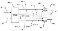
(オフセット検出方法)
次に、オフセット検出部40における視差の分離とオフセット検出方法の詳細を説明する。オフセット検出部40の構成図を図11に示す。
ベクトル分離部140は、左右ベクトルS31を成分分離して、水平方向成分を左原視差S141、垂直方向成分を左上下差S143(垂直方向のずれ量)として出力する。また、右左ベクトルS32を同様に分離して、水平方向成分を右原視差S142、垂直方向成分を右上下差S144(垂直方向のずれ量)として出力する。
符号反転部144は、右上下差S144の符号を反転して反転右上下差S145を出力する。
(Offset detection method)
Next, details of the parallax separation and the offset detection method in the offset
The
The
フィルタ143は、左上下差S143と反転右上下差S145を不図示のメモリに蓄積する。そして、左入力画像S1の注目ブロックとその周囲のブロックのそれぞれに対する左上下差を不図示のメモリから読み出す。また、右入力画像S2のブロックのうち、注目ブロックと位置が同じブロックとその周囲のブロックのそれぞれに対する反転右上下差を不図示のメモリから読み出す。そして、読み出した計18箇所の上下差にフィルタリングを施すことにより、それらの代表値を算出(決定)する。例えば、代表値として、メディアン(中間値)、平均値、最大値、最小値などを算出する。そして、代表値を上下オフセットS43として出力する。
The
一般に、注目ブロックの上下差と周囲のブロックの上下差はほぼ等しくなる。そのため、算出された上下差が正しければ、該上下差はフィルタリングにより得られた代表値とほぼ一致するはずである。
そこで、左検査部141は、ブロック毎に上下オフセットS43と左上下差S143を比較し、一致すれば左原視差S141を左視差S41として出力する。一致しなければ、左上下差(左右ベクトル)は誤りであると判断し、左視差S41として「ベクトル無し」を出力する。なお、上下オフセットS43と左上下差S143は完全に一致していなくてもよい。上下オフセットS43と左上下差S143の差が所定の値以下の場合に、それらが一致しているとみなしてもよい。
右検査部142は上下オフセットS43と反転右上下差S145を比較し、一致すれば右原視差S142を右視差S42に出力する。一致しなければ、右上下差(右左ベクトル)は誤りであると判断し、右視差S42として「ベクトル無し」を出力する。
In general, the vertical difference of the block of interest and the vertical difference of surrounding blocks are substantially equal. Therefore, if the calculated vertical difference is correct, the vertical difference should substantially match the representative value obtained by filtering.
Accordingly, the
The
このように、上下差にフィルタリングを施すことによってベクトル(左右ベクトルS31、右左ベクトルS32)の誤検出による画像の乱れを抑制することが可能となる。具体的には、注目ブロック領域S130に対する左右ベクトルS31と右左ベクトルS32は常に反転した関係になるとは限らない。しかし、同一個所に対する垂直方向のずれ量は左右画像間で同じになる。本実施例では、左右それぞれの画像から得られた左右ベクトルS31と右左ベクトルS32から垂直方向成分を分離して更にフィルタリングすることで、上下オフセットS43を安定して抽出することが可能となる。 In this way, by filtering the vertical difference, it is possible to suppress image disturbance due to erroneous detection of vectors (left and right vector S31, right and left vector S32). Specifically, the left / right vector S31 and the right / left vector S32 with respect to the block region of interest S130 are not always in an inverted relationship. However, the amount of vertical shift with respect to the same location is the same between the left and right images. In the present embodiment, the vertical offset S43 can be stably extracted by separating the vertical component from the left and right vectors S31 and right and left vectors S32 obtained from the left and right images and further filtering.
(補間画像生成方法)
次に、左右間補間画像生成部14における補間画像生成方法(2画像間補間処理)の詳細について説明する。左右間補間画像生成部14は上下オフセットS43(左上下差S143)の値によって3種類の補間方法を使い分ける。なお、右左間補間画像生成部24における2画像間補間処理も同様の考え方を適用すればよいため、説明は省略する。但し、右上下差S144ではなく上下オフセットS43が右左間補間画像生成部24に入力される場合、右左間補間画像生成部24は上下オフセットS43を符号を反転して用いる。
(Interpolated image generation method)
Next, details of the interpolation image generation method (inter-image interpolation process) in the left-right interpolation
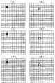
まず、上下オフセットS43の値が整数ライン分でかつ奇数であった場合の補間方法について説明する。この場合における補間方法の概念図を図12(A),(B)に示す。図12(A)は左入力画像S1を示す。図12(B)は右入力画像S2を表す。白部は入力されたラインを示す。斜線部は飛び越し走査によって飛び越された、補間が必要なライン(存在しないライン)を示す。Xは生成する補間画素である。丸印は、補間画素Xの生成位置に対しベクトル(上下オフセットS43と左視差S41)が指し示した位置である。
上下オフセットS43が奇数の場合には、右入力画像S2において、左入力画像S1の補間ラインの生成位置から上下オフセットS43の分だけずれた位置にラインが存在する。そのような場合には、右入力画像S2における該ラインを用いて補間ラインを生成する。具体的には、左視差と上下オフセットが指し示した丸印の位置に、右入力画像S2の画素bが存在するため、補間画素Xの値として画素bの値を用いる。
First, an interpolation method when the value of the vertical offset S43 is an integer line and an odd number will be described. A conceptual diagram of the interpolation method in this case is shown in FIGS. FIG. 12A shows the left input image S1. FIG. 12B represents the right input image S2. The white part indicates the input line. The hatched portion indicates a line that needs to be interpolated (a line that does not exist) that has been skipped by interlaced scanning. X is an interpolation pixel to be generated. A circle is a position indicated by a vector (vertical offset S43 and left parallax S41) with respect to the generation position of the interpolation pixel X.
When the vertical offset S43 is an odd number, a line exists in the right input image S2 at a position shifted by the vertical offset S43 from the interpolation line generation position of the left input image S1. In such a case, an interpolation line is generated using the line in the right input image S2. Specifically, since the pixel b of the right input image S2 exists at the position of the circle indicated by the left parallax and the vertical offset, the value of the pixel b is used as the value of the interpolation pixel X.
次に、上下オフセットS43の値が整数ライン分でかつ偶数であった場合の補間方法について説明する。この場合における補間方法の概念図を図12(C),(D)に示す。図12(C)は左入力画像S1を示す。図12(D)は右入力画像S2を表す。wは補間画素Xの上のラインに位置する画素、yは補間画素Xの下のラインに位置する画素である。その他の図画の意味は図12(A),(B)と同様である。
上下オフセットS43が偶数の場合には、右入力画像S2において、左入力画像S1の補間ラインの生成位置から上下オフセットS43の分だけずれた位置にラインが存在しない。そのような場合には、左入力画像S1における該補間ラインの生成位置の上下のラインを用いて補間ラインを生成する。具体的には、左視差と上下オフセットが指し示した丸印の位置に右入力画像S2の画素が存在しないため、補間画素Xの値として、
X=(w+y)/2
で算出される値を用いる。
Next, an interpolation method when the value of the vertical offset S43 is an integer line and an even number will be described. A conceptual diagram of the interpolation method in this case is shown in FIGS. FIG. 12C shows the left input image S1. FIG. 12D represents the right input image S2. w is a pixel located on the line above the interpolation pixel X, and y is a pixel located on the line below the interpolation pixel X. The meanings of other drawings are the same as those shown in FIGS.
When the vertical offset S43 is an even number, no line exists in the right input image S2 at a position shifted by the vertical offset S43 from the interpolation line generation position of the left input image S1. In such a case, an interpolation line is generated using lines above and below the generation position of the interpolation line in the left input image S1. Specifically, since the pixel of the right input image S2 does not exist at the position of the circle indicated by the left parallax and the vertical offset, as the value of the interpolation pixel X,
X = (w + y) / 2
The value calculated in (1) is used.
次に、上下オフセットS43の値が整数ライン分でなかった場合の補間方法について説明する。この場合における補間方法の概念図を図12(E),(F)に示す。図12(E)は左入力画像S1を示す。図12(F)は右入力画像S2を表す。bは左視差と上下オフセットが指し示した位置の上のラインの画素、cは左視差と上下オフセットが指し示した位置の下のラインの画素である。その他の図画の意味は図12(A)〜(D)と同様である。
このような場合には、補間ラインの生成位置に対し、左入力画像S1における該生成位置の上下のライン、及び、右入力画像S2における該生成位置から上下オフセットの分だけずれた位置の上下のラインを用いて、補間ラインを生成する。具体的には、上下オフセットが整数ライン分でない場合には、左視差と上下オフセットが指し示した位置(1画素分の領域)の一部に右入力画像S2の画素bが存在する。そのため、補間画素Xの値として、左入力画像S1の線形補間から求めた値と右入力画像S2の線形補間から求めた値の平均値を用いる。例えば、左視差と上下オフセットが指し示した領域の半分に画素bが重なっている場合(視差とオフセットが指し示した位置から画素bまでの距離と画素cまでの距離が1:3である場合)には、補間画素Xの値として、
X={(w+y)/2+(3b/4+c/4)}/2
で算出される値を用いる。
Next, an interpolation method when the value of the vertical offset S43 is not an integer line will be described. A conceptual diagram of the interpolation method in this case is shown in FIGS. FIG. 12E shows the left input image S1. FIG. 12F represents the right input image S2. b is a pixel on the line above the position indicated by the left parallax and the vertical offset, and c is a pixel on the line below the position indicated by the left parallax and the vertical offset. The meanings of the other drawings are the same as those shown in FIGS.
In such a case, with respect to the generation position of the interpolation line, the line above and below the generation position in the left input image S1 and the position above and below the position shifted by the vertical offset from the generation position in the right input image S2. An interpolation line is generated using the line. Specifically, when the vertical offset is not an integer line, the pixel b of the right input image S2 exists at a part of the position (region for one pixel) indicated by the left parallax and the vertical offset. Therefore, as the value of the interpolation pixel X, an average value of a value obtained from linear interpolation of the left input image S1 and a value obtained from linear interpolation of the right input image S2 is used. For example, when the pixel b overlaps half of the area indicated by the left parallax and the vertical offset (when the distance from the position indicated by the parallax and the offset to the pixel b and the distance to the pixel c is 1: 3). Is the value of the interpolated pixel X,
X = {(w + y) / 2 + (3b / 4 + c / 4)} / 2
The value calculated in (1) is used.
(画素選択方法)
次に左画素選択部15における画素選択方法(ライン補間処理)の詳細について説明する。
左入力画像S1に元から含まれていて補間の必要がない画素はそのまま選択される。
補間が必要な画素の選択方法は以下の通りである。
左動き検出信号S11の判定が“動きなし”であった位置に対しては、補間画素として左フィールド間補間画像S13の画素が選択される。
左動き検出信号S11の判定が“動きあり”で、かつ左視差S41が存在している位置に対しては、補間画素として左右間補間画像S14の画素が選択される。
左動き検出信号S11の判定が“動きあり”で、かつ左視差S41が存在しない位置に対しては、補間画素として左フィールド内補間画像S12の画素が選択される。
即ち、補間ラインを生成する際に、画像の動きのない領域内にはフィールド間補間処理により補間画素を生成し、画像の動きのある領域内には2画像間補間処理により補間画素を生成する。更に、画像の動きのある領域内であって、且つ、算出されたずれ量(左上下差)が誤りであると判断された分割領域内(ブロック内)には、フィールド内補間処理により補間画素を生成する。
それにより、左出力画像S15の各画素が選択されて出力される。
なお、ライン補間に伴う画素クロックの変動や各補間処理に伴う処理遅れ時間については、不図示のラインメモリまたはフレームメモリを用いて適宜調整を行う。
なお、右画素選択部25における画素選択方法も同様である。
(Pixel selection method)
Next, details of the pixel selection method (line interpolation process) in the left
Pixels that are originally included in the left input image S1 and need not be interpolated are selected as they are.
The method for selecting pixels that require interpolation is as follows.
For the position where the determination of the left motion detection signal S11 is “no motion”, the pixel of the inter-left field interpolated image S13 is selected as the interpolation pixel.
For the position where the determination of the left motion detection signal S11 is “with motion” and the left parallax S41 is present, the pixel of the left-right interpolated image S14 is selected as the interpolation pixel.
For a position where the determination of the left motion detection signal S11 is “with motion” and the left parallax S41 does not exist, a pixel of the intra-left-field interpolation image S12 is selected as an interpolation pixel.
That is, when generating an interpolation line, an interpolation pixel is generated by inter-field interpolation processing in a region where there is no image motion, and an interpolation pixel is generated by interpolation processing between two images in a region where the image moves. . Furthermore, in a region where there is a motion of the image, and in a divided region (in a block) where the calculated shift amount (left top and bottom difference) is determined to be incorrect, interpolated pixels are obtained by intra-field interpolation processing. Is generated.
Thereby, each pixel of the left output image S15 is selected and output.
Note that pixel clock fluctuations associated with line interpolation and processing delay times associated with each interpolation process are appropriately adjusted using a line memory or a frame memory (not shown).
The pixel selection method in the right
従来の動き適応型走査線補間処理では、画像の動きのある領域(動画領域)の補間画素の値は上下ラインの平均となるため、垂直方向の解像度が低下してしまう。一方、本実施例によれば、第1画像のライン間を補間する際に、該第1画像と対となる第2画像のラインを用いて補間ラインが生成される。それにより、従来に比べて動画領域の垂直方向の解像度が向上されたプログレッシブ映像を得ることができる。更に、本実施例によれば、第1画像に補間ラインを生成する際に、第1画像と第2画像の垂直方向のずれ量を考慮して、用いる第2画像のラインが選択される。そのため、第1画像のライン間を精度良く補間することができる(補間ラインに対応するラインとして誤ったラインを選択することを抑制できる)。
また、本実施例の構成によれば、立体映像を構成する2つの映像をそれぞれ高画質なプ
ログレッシブ映像に変換できるため、高画質なプログレッシブ方式の立体映像を得ることができる。
また、本実施例によれば、上記対となる画像から補間ラインの生成位置に対応するライン(高画質化のためのライン)が見つからなかった場合には、従来のライン補間処理と同等の動作が行われる。そのため、従来のライン補間処理と比べ、常に同等以上の画質を得ることが可能である。
また、本実施例では、ブロック毎に、そのブロックの上下オフセットを用いて補間ラインを生成することにより、画面内に一様でないオフセットが存在する場合にも対応することができる。例えば、ブロック単位で補間ラインを生成することにより、第1画像に対し第2画像が傾いた画像である場合や、第1画像に対し第2画像が拡大/縮小された画像である場合などにも対応することが可能となる。
In the conventional motion-adaptive scanning line interpolation processing, the value of the interpolation pixel in the region (moving image region) where the image moves is the average of the upper and lower lines, so the vertical resolution is lowered. On the other hand, according to the present embodiment, when interpolating between the lines of the first image, an interpolation line is generated using the line of the second image that is paired with the first image. Thereby, it is possible to obtain a progressive video in which the resolution in the vertical direction of the moving image area is improved as compared with the conventional case. Furthermore, according to the present embodiment, when generating an interpolation line in the first image, the line of the second image to be used is selected in consideration of the amount of vertical shift between the first image and the second image. Therefore, it is possible to interpolate between the lines of the first image with high precision (selecting an incorrect line as a line corresponding to the interpolation line can be suppressed).
In addition, according to the configuration of the present embodiment, since the two videos constituting the stereoscopic video can be converted into high-quality progressive video, high-quality progressive stereoscopic video can be obtained.
Further, according to the present embodiment, when a line corresponding to the generation position of the interpolation line (a line for improving the image quality) is not found from the paired images, an operation equivalent to the conventional line interpolation processing is performed. Is done. Therefore, it is possible to always obtain the same or better image quality as compared with the conventional line interpolation processing.
Further, in this embodiment, by generating an interpolation line for each block using the vertical offset of the block, it is possible to cope with a case where there is a non-uniform offset in the screen. For example, when an interpolation line is generated in units of blocks, the second image is an inclined image with respect to the first image, or the second image is an enlarged / reduced image with respect to the first image. Can also be supported.
なお、3つ以上の映像から構成されるインテグラル方式の立体映像についても、そのうちから2つの映像(通常は隣り合う視点の映像)を取り出すことで、本発明によるライン間の補間を実施することも可能である。
なお、対象とする画像は立体映像を構成する映像のフィールドに限らない。例えば、映像ではなく1枚の画像であってもよい。対を成す2つ以上の画像が相関性のある画像(同一対象を異なる視点から撮影した画像)であればよい。
なお、本実施例では、左入力画像S1と右入力画像S2(第1画像と第2画像)の両方のライン間を補間する構成としたが、一方の画像のライン間を補間する構成であってもよい。その場合には、補間の対象となる画像が第1画像となる。
なお、本実施例では、第1映像と第2映像の両方がインタレース映像である場合について説明したが、第2映像はプログレッシブ映像であってもよい。
なお、本実施例では、補間画素の生成位置毎に画像の動きを検出する構成としたが、動き検出の方法はこれに限らない。例えば、ブロックマッチング法などを用いて、所定の大きさの領域毎に動きの有無を検出してもよい。
なお、左右ベクトルや右左ベクトルが、第2画像の水平方向に隣接する画素間を指し示す場合には、該水平方向に隣接する画素を用いて補間画素を生成してもよい。
なお、各補間処理は、上述した方法に限らない。例えば、図5において、左フィールド間補間画像生成部13は、画素a1や画素b1の値を補間画素d1の値としてもよい。
なお、本実施例では、分割領域毎に垂直方向のずれを算出する構成としたが、全画像領域に対して1つのずれ量を算出する構成であってもよい。そのような構成であっても、従来に比べより高精度なライン間補間処理を実現できる。
なお、本実施例では、算出された垂直方向のずれが誤り否かを判断する構成としたが、そのような判断を行わずとも、従来に比べより高精度なライン間補間処理を実現できる。また、そのような判断に用いる代表値の決定方法は、上述した方法に限らない。例えば、代表値を決定する際に、第2画像に対して算出されたずれ量は含めなくてもよい。
In addition, with regard to the integral type stereoscopic video composed of three or more videos, the interpolation between the lines according to the present invention is performed by taking out two videos (usually videos of adjacent viewpoints) from among them. Is also possible.
Note that the target image is not limited to a video field that forms a stereoscopic video. For example, one image may be used instead of a video. It is sufficient that two or more images forming a pair are correlated images (images of the same object taken from different viewpoints).
In the present embodiment, the configuration is such that the lines between both the left input image S1 and the right input image S2 (the first image and the second image) are interpolated. May be. In that case, the image to be interpolated is the first image.
In addition, although the present Example demonstrated the case where both a 1st image | video and a 2nd image | video were interlaced images, a 2nd image | video may be a progressive image | video.
In the present embodiment, the image motion is detected for each interpolation pixel generation position, but the motion detection method is not limited to this. For example, the presence or absence of motion may be detected for each area of a predetermined size using a block matching method or the like.
When the left / right vector and the right / left vector indicate between pixels adjacent in the horizontal direction of the second image, an interpolation pixel may be generated using the pixels adjacent in the horizontal direction.
Each interpolation process is not limited to the method described above. For example, in FIG. 5, the inter-left field interpolated
In the present embodiment, the vertical shift is calculated for each divided area, but one shift amount may be calculated for all image areas. Even with such a configuration, it is possible to realize inter-line interpolation processing with higher accuracy than in the past.
In this embodiment, it is determined whether or not the calculated vertical shift is an error. However, even if such a determination is not made, it is possible to realize inter-line interpolation processing with higher accuracy than in the prior art. Moreover, the method of determining the representative value used for such determination is not limited to the method described above. For example, when determining the representative value, the shift amount calculated for the second image may not be included.
<実施例2>
実施例1では再生機1から左右独立した映像ストリーム(左入力映像と右入力映像)が出力される構成であった。本発明は、放送等で用いられているサイドバイサイド方式の立体映像(1つの映像ストリームの左右に左入力映像と右入力映像を左右に並べた立体映像)に対しても実施することができる。
実施例2に係る立体映像表示システムの構成図を図13に示す。
放送受信機4はサイドバイサイド方式による放送を受信してサイドバイサイド立体映像S4を出力する。
左ラインバッファ5は、サイドバイサイド立体映像S4を入力して、ラインの左半分の画素をメモリに書き込む。読出し側ではメモリに書かれた画素を読み出して左入力画像S1を出力する。
右ラインバッファ6は、サイドバイサイド立体映像S4を入力して、ラインの右半分の
画素をメモリに書き込む。読出し側ではメモリに書かれた画素を読み出して右入力画像S2を出力する。
IP変換部2は実施例1と同様のライン補間処理を行う。
また、以上の動作タイミングの制御は不図示の制御部が行う。この動作タイミングの概念図を図14に示す。図中、1Hは1ラインを走査する期間を表し、Filx1(x1は1以上
の整数)はx番目のフィールドを表す。oddはそのフィールドが奇数番目のラインのみを有すること(oddフィールドであること)を表し、evenはそのフィールドが偶数番目のライ
ンのみを有すること(evenフィールドであること)を表す。Linex2(x2は1以上の整数)はx2番目のラインを表し、Left,Rightはそのラインがそれぞれ左入力画像、右入力画像
のラインであることを表す。
このようにして、サイドバイサイド方式立体映像についても本発明を実施することが可能である。
<Example 2>
In the first embodiment, the left and right independent video streams (left input video and right input video) are output from the
FIG. 13 shows a configuration diagram of a stereoscopic video display system according to the second embodiment.
The broadcast receiver 4 receives a side-by-side broadcast and outputs a side-by-side stereoscopic video S4.
The
The
The
The above operation timing is controlled by a control unit (not shown). A conceptual diagram of this operation timing is shown in FIG. In the figure, 1H represents a period during which one line is scanned, and Filx1 (x1 is an integer of 1 or more) represents the xth field. odd represents that the field has only odd-numbered lines (is an odd field), and even represents that the field has only even-numbered lines (is an even field). Linex2 (x2 is an integer equal to or greater than 1) represents the x2th line, and Left and Right represent that the lines are the left input image and the right input image, respectively.
In this way, the present invention can also be implemented for side-by-side stereoscopic video.
<実施例3>
本発明は、フィールドシーケンシャル方式の立体映像に対しても実施することができる。フィールドシーケンシャル方式は、左入力映像のフィールドと右入力映像のフィールとを交互に繰り返す方式である。
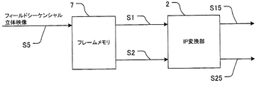
実施例3に係る立体映像表示システムの構成図を図15に示す。
不図示の映像入力部から入力されたフィールドシーケンシャル立体映像S5はフレームメモリ7に蓄えられる。不図示の制御手段は入力された映像信号のフィールドを並び替えて左入力画像S1および右入力画像S2を出力する。このときの動作タイミングの概念図を図16(A)に示す。
IP変換部2は実施例1と同様のライン補間処理を行う。
<Example 3>
The present invention can also be implemented for field sequential 3D video. The field sequential method is a method in which the field of the left input video and the field of the right input video are alternately repeated.
FIG. 15 shows a configuration diagram of a stereoscopic video display system according to the third embodiment.
A field sequential stereoscopic video S5 input from a video input unit (not shown) is stored in the frame memory 7. Control means (not shown) rearranges the fields of the input video signal and outputs the left input image S1 and the right input image S2. A conceptual diagram of the operation timing at this time is shown in FIG.
The
また、フィールド格納順序が異なるフィールドシーケンシャル方式の立体映像についても同様にフレームメモリでの並び替えを用いることによって本発明を実施することが可能である。フィールド格納順序が異なる場合の動作タイミングの概念図を図16(B)に示す。このフィールド格納順序の場合は、左入力画像S1としては常にoddフィールド、右
入力画像S2のフィールドとしては常にevenフィールドの状態で入力される。
この場合は、実施例1に説明した状況と比較してオフセットが1ずれていると考えて動作を修正する。具体的には、左右間補間画像生成部14は、上下オフセットS43の値が整数ライン分でかつ偶数であった場合に、右入力画像のラインを用いた補間を行う。また、上下オフセットS43の値が整数でかつ奇数であった場合には、左入力画像のラインを用いて補間ラインを生成する。右左間補間画像生成部24の動作も同様に修正する。
また、この場合には、フィールド間補間処理を行うことができないため、左画素選択部15は、“動きなし”の位置に対して、左右間補間画像S14の画素を選択する。右画素選択部25の動作も同様に修正する。
このようにして、フィールドシーケンシャル方式の立体映像についても本発明を実施することが可能である。
In addition, the present invention can be implemented by using rearrangement in the frame memory in the same manner for field sequential 3D images having different field storage orders. FIG. 16B shows a conceptual diagram of operation timing when the field storage order is different. In this field storage order, the left input image S1 is always input in the odd field, and the right input image S2 is always input in the even field.
In this case, the operation is corrected assuming that the offset is deviated by 1 compared to the situation described in the first embodiment. Specifically, the left-right interpolated
Further, in this case, since inter-field interpolation processing cannot be performed, the left
In this manner, the present invention can also be implemented for field sequential 3D video.
<実施例4>
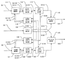
以上説明した実施例では入力された立体映像に自然に存在する上下オフセットを検出するものとしたが、映像コンテンツの上下オフセットを予め厳密に調整しておくことでさらに高精度な走査線補間を行うことも可能である。
実施例4における映像コンテンツ作成システムの概念図を図17に示す。図中、Lx3(x3は1以上の整数)はプログレッシブ方式の左入力画像のラインを表し、Rx4(x4は1以上の整数)はプログレッシブ方式の右入力画像のラインを表す。ODDは、プログレッシブ方
式の左入力画像、右入力画像からインタレース化により作成された奇数番目のラインのみを有する画像を表す。EVENは、プログレッシブ方式の左入力画像、右入力画像からインタレース化により作成された奇数番目のラインのみを有する画像を表す。Fx5(x5は1以上
の整数)は、その画像がインタレース化された左入力映像、右入力映像のx5番目のフィールドであることを表す。なお、図17では、簡単のため、プログレッシブ方式の左入力画像と右入力画像が6つのラインで構成されている例を示しているが、これに限定するものではない(ライン数はいくつでもよい)。
本実施例では、左入力映像と右入力映像を作成するステレオ撮像機に対して、上下オフセットが出ないように予め光軸のアライメントを行っておく。また、本実施例では、この撮像機において、プログレッシブ方式の立体映像(プログレッシブ方式の左入力映像と右入力映像)が作成されるものとする。そして、一方の映像(本実施例では左入力映像)に対しては通常のインタレース化を行い、他方の映像(右入力映像)に対しては1ライン分の上下オフセットをつけたオフセットインタレース化を行う。さらに、映像コンテンツ(インタレース化された立体映像)に左入力画像S1と右入力画像S2の間の垂直方向のずれ量を表すメタデータを付加する。本実施例では、1ライン分の上下オフセットの存在を示すメタデータ「上下オフセット=1」が付加される。
<Example 4>
In the embodiment described above, the vertical offset that naturally exists in the input stereoscopic video is detected. However, by precisely adjusting the vertical offset of the video content in advance, more accurate scanning line interpolation is performed. It is also possible.
A conceptual diagram of a video content creation system in the fourth embodiment is shown in FIG. In the figure, Lx3 (x3 is an integer of 1 or more) represents a line of a progressive left input image, and Rx4 (x4 is an integer of 1 or more) represents a line of a progressive right input image. ODD represents an image having only odd-numbered lines created by interlaced from a progressive left input image and a right input image. EVEN represents an image having only odd-numbered lines created by interlaced from a progressive left input image and a right input image. Fx5 (x5 is an integer of 1 or more) represents that the image is the x5th field of the left input video and the right input video that are interlaced. Note that FIG. 17 shows an example in which the progressive left input image and the right input image are composed of six lines for the sake of simplicity, but the present invention is not limited to this (the number of lines may be any number). ).
In this embodiment, the optical axes are aligned in advance so as not to cause a vertical offset with respect to the stereo imaging device that creates the left input video and the right input video. Further, in this embodiment, it is assumed that a progressive stereoscopic video (progressive left input video and right input video) is created in this imaging device. Then, normal interlacing is performed on one video (left input video in this embodiment), and offset interlace with a vertical offset of one line is applied to the other video (right input video). To do. Further, metadata representing the vertical shift amount between the left input image S1 and the right input image S2 is added to the video content (interlaced stereoscopic video). In this embodiment, metadata “up / down offset = 1” indicating the presence of up / down offset for one line is added.
IP変換部ではメタデータを用いて高精度なライン補間処理を行う。具体的には、左右比較部43において、メタデータが表すずれ量(上下オフセット)が用いられる。上記実施例と同じ機能や信号については同じ符号を付し、説明は省略する。
不図示のメタデータ取得部より取得したメタデータS3は左右比較部43に入力される。ベクトル発生部413は、探索ベクトルを発生する際に、垂直方向成分の値を予め取得したメタデータによる上下オフセットの値に限定する。
The IP conversion unit performs highly accurate line interpolation processing using metadata. Specifically, the left /
Metadata S3 acquired from a metadata acquisition unit (not shown) is input to the left /
本実施例の構成によれば、安定した左右の視差の探索が可能となる(左右ベクトルS31、右左ベクトルS32の誤検出を抑制できる)。また探索範囲が狭くなるので本発明を実施するためのハードウェア規模を小さくすることが可能となる。
また、常に1ラインずれた理想的な上下オフセットが得られるため、左右間補間画像生成部14は、常に右入力画像の画素を用いた補間を行うことができる(右左間補間画像生成部24も同様に、常に左入力画像の画素を用いた補間を行うことができる)。それにより、ライン補間処理の結果(例えば、プログレッシブ映像)をより高画質化することができる。
According to the configuration of the present embodiment, it is possible to search for stable left and right parallax (error detection of the left and right vector S31 and the right and left vector S32 can be suppressed). Moreover, since the search range is narrowed, the hardware scale for carrying out the present invention can be reduced.
In addition, since an ideal vertical offset shifted by one line is always obtained, the interpolated
なお、立体映像の上下オフセットが1ライン程度残存した状態でも、通常の立体映像再生システムにおいて特に違和感無く再生することができる。そのため、本実施例の映像コンテンツ作成システムで作成された立体映像コンテンツは通常の立体映像再生システムにおいても何ら不具合は無く再生することができる。
なお、本実施例では、ステレオ撮像機に対して、上下オフセットが出ないように予め光軸のアライメントを行っておくものとしたが、ステレオ撮像機の光軸を厳密に1ラインずらしておいてもよい。それにより、1ライン分の上下オフセットを得ることができる。また、その場合には、ステレオ撮像機で作成された左入力映像と右入力映像の両方に対して通常のインタレース化を行えばよい。
また、ステレオ撮像機の光軸が厳密に合わせられていない場合には、上下オフセットが1ライン分になるように、左入力映像と右入力映像を画像処理により調整してもよい。
Even in the state where the vertical offset of the stereoscopic video remains about one line, it can be reproduced without any particular discomfort in a normal stereoscopic video reproduction system. For this reason, the stereoscopic video content created by the video content creation system of the present embodiment can be reproduced without any problem even in a normal stereoscopic video reproduction system.
In this embodiment, the optical axis is aligned in advance so as not to cause a vertical offset with respect to the stereo image pickup device, but the optical axis of the stereo image pickup device is shifted by exactly one line. Also good. Thereby, a vertical offset for one line can be obtained. In this case, normal interlacing may be performed on both the left input video and the right input video created by the stereo imaging device.
Further, when the optical axis of the stereo image pickup device is not strictly aligned, the left input video and the right input video may be adjusted by image processing so that the vertical offset is one line.
12 左フィールド内補間画像生成部
13 左フィールド間補間画像生成部
14 左右間補間画像生成部
15 左画素選択部
30 左右比較部
40 オフセット検出部
12 Interpolated image generating unit in
Claims (20)
前記第1画像と前記第2画像を比較し、それらの画像間の垂直方向のずれ量を算出する算出手段と、
前記ずれ量が誤りであるか否かを判定する判定手段と、
前記ずれ量と前記判定手段の判定結果に基づいて、前記第1画像のライン間に補間ラインを生成する生成手段と、
を有し、
前記生成手段は、
前記ずれ量が誤りではないと判定された場合、補間ラインの生成位置に対し、前記第2画像において該生成位置から前記ずれ量の分だけずれた位置に存在するラインを用いて補間ラインを生成する2画像間補間処理により補間画素を生成し、
前記ずれ量が誤りであると判定された場合、フィールド内補間処理により補間画素を生成することを特徴とする画像処理装置。 An image processing apparatus that interpolates between lines of the first image using a first image and a second image obtained by photographing the same object from different viewpoints,
A calculating means for comparing the first image with the second image and calculating a vertical shift amount between the images;
Determination means for determining whether or not the deviation amount is an error;
Generating means for generating an interpolation line between lines of the first image based on the deviation amount and the determination result of the determining means;
Have
The generating means includes
If it is determined that the shift amount is not an error, an interpolation line is generated using a line that exists at a position shifted from the generation position by the shift amount in the second image with respect to the generation position of the interpolation line. Interpolating between two images by generating interpolation pixels,
When it is determined that the deviation amount is an error, an image processing apparatus is characterized in that an interpolation pixel is generated by intra-field interpolation processing .
前記生成手段は、分割領域毎に補間ラインを生成することを特徴とする請求項1に記載の画像処理装置。 The calculation means divides the first image into a plurality of divided areas, calculates the shift amount for each divided area,
The image processing apparatus according to claim 1, wherein the generation unit generates an interpolation line for each divided region.
補間ラインの生成位置に対し、前記第2画像において該生成位置から前記ずれ量の分だけずれた位置にラインが存在する場合には、前記第2画像における該ラインを用いて補間ラインを生成し、
補間ラインの生成位置に対し、前記第2画像において該生成位置から前記ずれ量の分だけずれた位置にラインが存在しない場合には、前記第1画像における該生成位置の上下のラインを用いて補間ラインを生成する処理であることを特徴とする請求項1または2に記載の画像処理装置。 The interpolation between the two images includes
When a line exists in the second image at a position shifted from the generation position by the amount of shift with respect to the generation position of the interpolation line, an interpolation line is generated using the line in the second image. ,
When there is no line in the second image at a position shifted from the generation position by the shift amount with respect to the generation position of the interpolation line, the lines above and below the generation position in the first image are used. The image processing apparatus according to claim 1, wherein the image processing apparatus generates an interpolation line.
補間ラインの生成位置に対し、前記ずれ量が整数ライン分でない場合には、前記第1画像における該生成位置の上下のライン、及び、前記第2画像における該生成位置から前記ずれ量の分だけずれた位置の上下のラインを用いて、補間ラインを生成する処理であることを特徴とする請求項3に記載の画像処理装置。 The interpolation between the two images further includes:
When the shift amount is not an integer line amount relative to the generation position of the interpolation line, the shift amount is equal to the shift amount from the generation position in the second image and the lines above and below the generation position in the first image. The image processing apparatus according to claim 3, wherein the image processing apparatus is a process of generating an interpolation line using upper and lower lines at a shifted position.
前記画像処理装置は、前記第1画像の動きを検出する動き検出手段を更に有し、
前記生成手段は、補間ラインを生成する際に、
前記第1画像の動きのない領域内にはフィールド間補間処理により補間画素を生成し、
前記第1画像の動きのある領域内には前記2画像間補間処理により補間画素を生成することを特徴とする請求項1〜4のいずれか1項に記載の画像処理装置。 The first image is a field of interlaced video;
The image processing apparatus further includes motion detection means for detecting the motion of the first image,
The generating means generates an interpolation line when:
An interpolated pixel is generated by inter-field interpolation processing in a region where the first image does not move,
5. The image processing apparatus according to claim 1, wherein an interpolation pixel is generated by an inter-two-image interpolation process in an area in which the first image moves. 6.
前記判定手段は、注目する分割領域に対するずれ量と、前記注目する分割領域とその周囲の分割領域のそれぞれに対するずれ量の代表値とを比較することにより、前記注目する分割領域に対するずれ量が誤りか否かを判断することを特徴とする請求項1〜6のいずれか1項に記載の画像処理装置。 The determination unit compares the shift amount with respect to the target divided region with a representative value of the shift amount with respect to each of the target split region and the surrounding split regions, so that the shift amount with respect to the target split region is incorrect. 7. The image processing apparatus according to claim 1, wherein the image processing apparatus determines whether the image processing is in progress.
前記判定手段は、前記第2画像の分割領域のうち、前記注目する分割領域と位置が同じ分割領域とその周囲の分割領域に対するずれ量の符号を反転したものを更に含めて、前記代表値を決定することを特徴とする請求項7に記載の画像処理装置。 The calculation means divides the second image into a plurality of divided areas in the same manner as the first image, and further calculates the shift amount for each divided area of the second image,
The determination means further includes the representative value including the one obtained by inverting the sign of the shift amount with respect to the divided area having the same position as the noticed divided area and the surrounding divided areas among the divided areas of the second image. The image processing apparatus according to claim 7 , wherein the determination is performed.
前記算出手段は、前記メタデータが表すずれ量を用いることを特徴とする請求項1〜8のいずれか1項に記載の画像処理装置。 An acquisition unit for acquiring metadata representing a vertical shift amount between the first image and the second image;
It said calculating means, an image processing apparatus according to any one of claims 1-8, characterized by using the shift amount at which the metadata represented.
前記算出手段は、前記第1画像を複数の分割領域に分割し、前記第2画像との間でブロックマッチングを行うことにより、分割領域毎にずれ量を算出するものであって、 The calculating means calculates the amount of deviation for each divided region by dividing the first image into a plurality of divided regions and performing block matching with the second image,
前記第1画像が左目用画像である場合、ブロックマッチングで探索する範囲は注目する分割領域の位置に対して左側の方が右側より広く、 When the first image is a left-eye image, the search range by block matching is wider on the left side than the right side with respect to the position of the divided region of interest.
前記第1画像が右目用画像である場合、ブロックマッチングで探索する範囲は注目する分割領域の位置に対して右側の方が左側より広い When the first image is a right-eye image, the search range by block matching is wider on the right side than the left side with respect to the position of the divided region of interest.
ことを特徴とする請求項1〜9のいずれか1項に記載の画像処理装置。The image processing apparatus according to claim 1, wherein the image processing apparatus is an image processing apparatus.
前記第1画像と前記第2画像を比較し、それらの画像間の垂直方向のずれ量を算出する算出ステップと、
前記ずれ量が誤りであるか否かを判定する判定ステップと、
前記ずれ量と前記判定ステップの判定結果に基づいて、前記第1画像のライン間に補間ラインを生成する生成ステップと、
を有し、
前記生成ステップでは、
前記ずれ量が誤りではないと判定された場合、補間ラインの生成位置に対し、前記第2画像において該生成位置から前記ずれ量の分だけずれた位置に存在するラインを用いて補間ラインを生成する2画像間補間処理により補間画素を生成し、
前記ずれ量が誤りであると判定された場合、フィールド内補間処理により補間画素を生成することを特徴とする画像処理装置の制御方法。 A control method of an image processing apparatus that interpolates between lines of the first image using a first image and a second image obtained by photographing the same object from different viewpoints,
A calculation step of comparing the first image with the second image and calculating a vertical shift amount between the images;
A determination step of determining whether or not the deviation amount is an error;
A generation step of generating an interpolation line between lines of the first image based on the amount of deviation and the determination result of the determination step;
Have
In the generating step,
If it is determined that the shift amount is not an error, an interpolation line is generated using a line that exists at a position shifted from the generation position by the shift amount in the second image with respect to the generation position of the interpolation line. Interpolating between two images by generating interpolation pixels,
An image processing apparatus control method, comprising: generating an interpolation pixel by intra-field interpolation processing when it is determined that the shift amount is an error .
前記生成ステップでは、分割領域毎に補間ラインを生成することを特徴とする請求項11に記載の画像処理装置の制御方法。 In the calculating step, the first image is divided into a plurality of divided areas, and the shift amount is calculated for each divided area.
The method of controlling an image processing apparatus according to claim 11 , wherein in the generation step, an interpolation line is generated for each divided region.
補間ラインの生成位置に対し、前記第2画像において該生成位置から前記ずれ量の分だけずれた位置にラインが存在する場合には、前記第2画像における該ラインを用いて補間ラインを生成し、
補間ラインの生成位置に対し、前記第2画像において該生成位置から前記ずれ量の分だけずれた位置にラインが存在しない場合には、前記第1画像における該生成位置の上下のラインを用いて補間ラインを生成する処理であることを特徴とする請求項11または12に記載の画像処理装置の制御方法。 The interpolation between the two images includes
When a line exists in the second image at a position shifted from the generation position by the amount of shift with respect to the generation position of the interpolation line, an interpolation line is generated using the line in the second image. ,
When there is no line in the second image at a position shifted from the generation position by the shift amount with respect to the generation position of the interpolation line, the lines above and below the generation position in the first image are used. method of controlling an image processing apparatus according to claim 11 or 12, characterized in that a process of generating the interpolation line.
補間ラインの生成位置に対し、前記ずれ量が整数ライン分でない場合には、前記第1画像における該生成位置の上下のライン、及び、前記第2画像における該生成位置から前記ずれ量の分だけずれた位置の上下のラインを用いて、補間ラインを生成する処理であることを特徴とする請求項13に記載の画像処理装置の制御方法。 The interpolation between the two images further includes:
When the shift amount is not an integer line amount relative to the generation position of the interpolation line, the shift amount is equal to the shift amount from the generation position in the second image and the lines above and below the generation position in the first image. The method of controlling an image processing apparatus according to claim 13 , wherein the process is a process of generating an interpolation line by using lines above and below the shifted position.
前記画像処理装置の制御方法は、前記第1画像の動きを検出する動き検出ステップを更に有し、
前記生成ステップでは、補間ラインを生成する際に、
前記第1画像の動きのない領域内にはフィールド間補間処理により補間画素を生成し、
前記第1画像の動きのある領域内には前記2画像間補間処理により補間画素を生成することを特徴とする請求項11〜14のいずれか1項に記載の画像処理装置の制御方法。 The first image is a field of interlaced video;
The control method of the image processing apparatus further includes a motion detection step of detecting a motion of the first image,
In the generating step, when generating the interpolation line,
An interpolated pixel is generated by inter-field interpolation processing in a region where the first image does not move,
The method of controlling an image processing apparatus according to any one of claims 11 to 14 , wherein an interpolation pixel is generated by an interpolation process between the two images in an area in which the first image moves.
前記判定ステップでは、注目する分割領域に対するずれ量と、前記注目する分割領域とその周囲の分割領域のそれぞれに対するずれ量の代表値とを比較することにより、前記注目する分割領域に対するずれ量が誤りか否かを判断することを特徴とする請求項11〜16のいずれか1項に記載の画像処理装置の制御方法。 In the determination step, the shift amount with respect to the target divided region is compared with a representative value of the shift amount with respect to each of the target split region and each of the surrounding split regions, so that the shift amount with respect to the target split region is erroneous. 17. The method of controlling an image processing apparatus according to claim 11, further comprising:
前記判定ステップでは、前記第2画像の分割領域のうち、前記注目する分割領域と位置が同じ分割領域とその周囲の分割領域に対するずれ量の符号を反転したものを更に含めて、前記代表値を決定することを特徴とする請求項17に記載の画像処理装置の制御方法。 In the calculating step, the second image is divided into a plurality of divided areas in the same manner as the first image, and the shift amount is further calculated for each divided area of the second image,
In the determination step, the representative value is further included by further inverting the sign of the shift amount with respect to the divided area having the same position as the noticed divided area and the surrounding divided areas among the divided areas of the second image. 18. The method according to claim 17 , wherein the control method is determined.
前記算出ステップでは、前記メタデータが表すずれ量を用いることを特徴とする請求項11〜18のいずれか1項に記載の画像処理装置の制御方法。 An acquisition step of acquiring metadata representing an amount of vertical displacement between the first image and the second image;
In the calculation step, a method of controlling an image processing apparatus according to any one of claims 11-18, which comprises using a shift amount which the metadata represented.
前記算出ステップでは、前記第1画像を複数の分割領域に分割し、前記第2画像との間でブロックマッチングを行うことにより、分割領域毎にずれ量を算出し、 In the calculating step, the first image is divided into a plurality of divided areas, and block matching is performed with the second image, thereby calculating a shift amount for each divided area,
前記第1画像が左目用画像である場合、ブロックマッチングで探索する範囲は注目する分割領域の位置に対して左側の方が右側より広く、 When the first image is a left-eye image, the search range by block matching is wider on the left side than the right side with respect to the position of the divided region of interest.
前記第1画像が右目用画像である場合、ブロックマッチングで探索する範囲は注目する分割領域の位置に対して右側の方が左側より広い When the first image is a right-eye image, the search range by block matching is wider on the right side than the left side with respect to the position of the divided region of interest.
ことを特徴とする請求項11〜19のいずれか1項に記載の画像処理装置の制御方法。The method for controlling an image processing apparatus according to claim 11, wherein:
Priority Applications (1)
| Application Number | Priority Date | Filing Date | Title |
|---|---|---|---|
| JP2010069926A JP5489809B2 (en) | 2010-03-25 | 2010-03-25 | Image processing apparatus and image processing apparatus control method |
Applications Claiming Priority (1)
| Application Number | Priority Date | Filing Date | Title |
|---|---|---|---|
| JP2010069926A JP5489809B2 (en) | 2010-03-25 | 2010-03-25 | Image processing apparatus and image processing apparatus control method |
Publications (3)
| Publication Number | Publication Date |
|---|---|
| JP2011205346A JP2011205346A (en) | 2011-10-13 |
| JP2011205346A5 JP2011205346A5 (en) | 2013-05-02 |
| JP5489809B2 true JP5489809B2 (en) | 2014-05-14 |
Family
ID=44881524
Family Applications (1)
| Application Number | Title | Priority Date | Filing Date |
|---|---|---|---|
| JP2010069926A Expired - Fee Related JP5489809B2 (en) | 2010-03-25 | 2010-03-25 | Image processing apparatus and image processing apparatus control method |
Country Status (1)
| Country | Link |
|---|---|
| JP (1) | JP5489809B2 (en) |
Families Citing this family (2)
| Publication number | Priority date | Publication date | Assignee | Title |
|---|---|---|---|---|
| WO2013108295A1 (en) * | 2012-01-20 | 2013-07-25 | パナソニック株式会社 | Video signal processing device and video signal processing method |
| JP2014187601A (en) * | 2013-03-25 | 2014-10-02 | Sony Corp | Image processing unit, image processing method and program |
Family Cites Families (11)
| Publication number | Priority date | Publication date | Assignee | Title |
|---|---|---|---|---|
| JPH06269025A (en) * | 1993-03-16 | 1994-09-22 | Fujitsu Ltd | Coding system for multi-eye stereoscopic video image |
| JPH089342A (en) * | 1994-06-16 | 1996-01-12 | Mitsubishi Electric Corp | High-vision signal receiver |
| JP3157384B2 (en) * | 1994-06-20 | 2001-04-16 | 三洋電機株式会社 | 3D image device |
| JPH1013860A (en) * | 1996-04-26 | 1998-01-16 | Victor Co Of Japan Ltd | Stereoscopic picture interpolating device and its method |
| JP2000156846A (en) * | 1998-11-19 | 2000-06-06 | Victor Co Of Japan Ltd | Device and method for converting moving image format |
| JP4424640B2 (en) * | 2000-10-20 | 2010-03-03 | 日本テレビ放送網株式会社 | Stereo video signal generation method and transmission method, and system thereof |
| JP2003296740A (en) * | 2002-04-08 | 2003-10-17 | Victor Co Of Japan Ltd | Object monitoring method and object monitoring camera device |
| JP4440067B2 (en) * | 2004-10-15 | 2010-03-24 | キヤノン株式会社 | Image processing program for stereoscopic display, image processing apparatus, and stereoscopic display system |
| JP2006128842A (en) * | 2004-10-27 | 2006-05-18 | Texnai:Kk | Stereoscopic video signal generator |
| JP4780046B2 (en) * | 2007-06-19 | 2011-09-28 | 日本ビクター株式会社 | Image processing method, image processing apparatus, and image processing program |
| JP5127633B2 (en) * | 2008-08-25 | 2013-01-23 | 三菱電機株式会社 | Content playback apparatus and method |
-
2010
- 2010-03-25 JP JP2010069926A patent/JP5489809B2/en not_active Expired - Fee Related
Also Published As
| Publication number | Publication date |
|---|---|
| JP2011205346A (en) | 2011-10-13 |
Similar Documents
| Publication | Publication Date | Title |
|---|---|---|
| JP5127633B2 (en) | Content playback apparatus and method | |
| JP5575891B2 (en) | Automatic 3D video format conversion method and apparatus | |
| JP5529870B2 (en) | 2D / 3D playback mode determination method, 2D / 3D playback mode determination device, and storage medium | |
| JP4438795B2 (en) | Video conversion device, video display device, and video conversion method | |
| JP5421647B2 (en) | Imaging apparatus and control method thereof | |
| JP2004159294A (en) | Frame interpolation and apparatus using the frame interpolation | |
| JP2010062695A (en) | Image processing apparatus, image processing method, and program | |
| JP2009244502A (en) | Image processing apparatus, image display apparatus, imaging apparatus and image processing method | |
| US8941718B2 (en) | 3D video processing apparatus and 3D video processing method | |
| JP5454569B2 (en) | 3D image data processing apparatus and 3D image data processing method | |
| JP5424926B2 (en) | Video processing apparatus and video processing method | |
| JP5489809B2 (en) | Image processing apparatus and image processing apparatus control method | |
| JP2005020606A (en) | Digital camera | |
| JP2009200985A (en) | Video processing apparatus | |
| US8330799B2 (en) | Image output apparatus and image output method | |
| US20150002624A1 (en) | Video signal processing device and video signal processing method | |
| JP2007129400A (en) | Film mode detector and video display | |
| JP5123643B2 (en) | Video processing device | |
| JP2013126123A (en) | Image processing device, imaging apparatus, and image processing method | |
| JP5700998B2 (en) | 3D image display apparatus and control method thereof | |
| WO2011114745A1 (en) | Video playback device | |
| JP2007288483A (en) | Image converting apparatus | |
| JP5090857B2 (en) | Image processing apparatus, image processing method, and program | |
| US8902286B2 (en) | Method and apparatus for detecting motion vector, and method and apparatus for processing image signal | |
| JP2009124261A5 (en) |
Legal Events
| Date | Code | Title | Description |
|---|---|---|---|
| A521 | Request for written amendment filed |
Free format text: JAPANESE INTERMEDIATE CODE: A523 Effective date: 20130314 |
|
| A621 | Written request for application examination |
Free format text: JAPANESE INTERMEDIATE CODE: A621 Effective date: 20130314 |
|
| A977 | Report on retrieval |
Free format text: JAPANESE INTERMEDIATE CODE: A971007 Effective date: 20131031 |
|
| A131 | Notification of reasons for refusal |
Free format text: JAPANESE INTERMEDIATE CODE: A131 Effective date: 20131112 |
|
| A521 | Request for written amendment filed |
Free format text: JAPANESE INTERMEDIATE CODE: A523 Effective date: 20140107 |
|
| TRDD | Decision of grant or rejection written | ||
| A01 | Written decision to grant a patent or to grant a registration (utility model) |
Free format text: JAPANESE INTERMEDIATE CODE: A01 Effective date: 20140128 |
|
| A61 | First payment of annual fees (during grant procedure) |
Free format text: JAPANESE INTERMEDIATE CODE: A61 Effective date: 20140225 |
|
| LAPS | Cancellation because of no payment of annual fees |