JP5488407B2 - Vehicle control device - Google Patents
Vehicle control device Download PDFInfo
- Publication number
- JP5488407B2 JP5488407B2 JP2010247282A JP2010247282A JP5488407B2 JP 5488407 B2 JP5488407 B2 JP 5488407B2 JP 2010247282 A JP2010247282 A JP 2010247282A JP 2010247282 A JP2010247282 A JP 2010247282A JP 5488407 B2 JP5488407 B2 JP 5488407B2
- Authority
- JP
- Japan
- Prior art keywords
- power
- storage device
- charging
- power storage
- vehicle
- Prior art date
- Legal status (The legal status is an assumption and is not a legal conclusion. Google has not performed a legal analysis and makes no representation as to the accuracy of the status listed.)
- Active
Links
Images


Classifications
-
- Y—GENERAL TAGGING OF NEW TECHNOLOGICAL DEVELOPMENTS; GENERAL TAGGING OF CROSS-SECTIONAL TECHNOLOGIES SPANNING OVER SEVERAL SECTIONS OF THE IPC; TECHNICAL SUBJECTS COVERED BY FORMER USPC CROSS-REFERENCE ART COLLECTIONS [XRACs] AND DIGESTS
- Y02—TECHNOLOGIES OR APPLICATIONS FOR MITIGATION OR ADAPTATION AGAINST CLIMATE CHANGE
- Y02E—REDUCTION OF GREENHOUSE GAS [GHG] EMISSIONS, RELATED TO ENERGY GENERATION, TRANSMISSION OR DISTRIBUTION
- Y02E60/00—Enabling technologies; Technologies with a potential or indirect contribution to GHG emissions mitigation
- Y02E60/10—Energy storage using batteries
-
- Y—GENERAL TAGGING OF NEW TECHNOLOGICAL DEVELOPMENTS; GENERAL TAGGING OF CROSS-SECTIONAL TECHNOLOGIES SPANNING OVER SEVERAL SECTIONS OF THE IPC; TECHNICAL SUBJECTS COVERED BY FORMER USPC CROSS-REFERENCE ART COLLECTIONS [XRACs] AND DIGESTS
- Y02—TECHNOLOGIES OR APPLICATIONS FOR MITIGATION OR ADAPTATION AGAINST CLIMATE CHANGE
- Y02T—CLIMATE CHANGE MITIGATION TECHNOLOGIES RELATED TO TRANSPORTATION
- Y02T10/00—Road transport of goods or passengers
- Y02T10/60—Other road transportation technologies with climate change mitigation effect
- Y02T10/62—Hybrid vehicles
Description
本発明は、車両の制御装置に関し、より特定的には、車両外部からの電力を用いて充電が可能な車両における、車両に搭載された蓄電装置の充放電制御に関する。 The present invention relates to a vehicle control device, and more particularly to charge / discharge control of a power storage device mounted on a vehicle in a vehicle that can be charged using electric power from outside the vehicle.
近年、環境に配慮した車両として、蓄電装置(たとえば二次電池やキャパシタなど)を搭載し、蓄電装置に蓄えられた電力から生じる駆動力を用いて走行する車両が注目されている。このような車両には、たとえば電気自動車、ハイブリッド自動車、燃料電池車などが含まれる。そして、これらの車両に搭載される蓄電装置を発電効率の高い商用電源により充電する技術が提案されている。 2. Description of the Related Art In recent years, attention has been paid to a vehicle that is mounted with a power storage device (for example, a secondary battery or a capacitor) and travels using driving force generated from electric power stored in the power storage device as an environment-friendly vehicle. Such vehicles include, for example, electric vehicles, hybrid vehicles, fuel cell vehicles, and the like. And the technique which charges the electrical storage apparatus mounted in these vehicles with a commercial power source with high electric power generation efficiency is proposed.
ハイブリッド車においても、電気自動車と同様に、車両外部の電源(以下、単に「外部電源」とも称する。)から車載の蓄電装置の充電(以下、単に「外部充電」とも称する。)が可能な車両が知られている。たとえば、家屋に設けられたコンセントと車両に設けられた充電口とを充電ケーブルで接続することにより、一般家庭の電源から蓄電装置の充電が可能ないわゆる「プラグイン・ハイブリッド車」が知られている。これにより、ハイブリッド自動車の燃料消費効率を高めることが期待できる。 In a hybrid vehicle as well as an electric vehicle, a vehicle capable of charging an in-vehicle power storage device (hereinafter also simply referred to as “external charging”) from a power source outside the vehicle (hereinafter also simply referred to as “external power source”). It has been known. For example, a so-called “plug-in hybrid vehicle” is known in which a power storage device can be charged from a general household power source by connecting an outlet provided in a house and a charging port provided in the vehicle with a charging cable. Yes. This can be expected to increase the fuel consumption efficiency of the hybrid vehicle.
このように電力を用いて走行する車両においては、各電流経路に設けられた部品は、一般的には、通常運転時(走行時)および外部充電時に流れる電流によって生じる発熱に耐え得るように、設計される。 In a vehicle that travels using electric power in this way, the components provided in each current path generally can withstand the heat generated by the current that flows during normal operation (during travel) and external charging. Designed.
特開2004−048885号公報(特許文献1)は、パルス幅変調を用いて電動機等の負荷に電力を供給する電力変換装置において、スイッチングパワー素子に流れる電流値の二乗を一次遅れ系に通した出力値に基づいて、電力変換装置に対する電圧指令値として2相変調用の電圧指令値を選択するか否かを判定する技術を開示する。一般的に、スイッチングパワー素子における発熱は電流値の二乗にほぼ比例し、発熱した熱の放熱は一次遅れ系で近似できることが知られている。そして、熱的時定数を事前に測定して記憶し、上述のように電流値の二乗を一次遅れ系の熱モデルに通した出力値を計算することによって、熱的な負荷を推定することができる。 Japanese Patent Laying-Open No. 2004-048885 (Patent Document 1) is a power conversion device that supplies electric power to a load such as an electric motor using pulse width modulation, and passes the square of a current value flowing through a switching power element through a first-order lag system. Disclosed is a technique for determining whether or not to select a voltage command value for two-phase modulation as a voltage command value for a power converter based on an output value. In general, it is known that heat generation in a switching power element is approximately proportional to the square of a current value, and heat dissipation of the generated heat can be approximated by a first-order lag system. The thermal time constant can be measured and stored in advance, and the thermal load can be estimated by calculating the output value obtained by passing the square of the current value through the thermal model of the first-order lag system as described above. it can.
したがって、特開2004−048885号公報(特許文献1)によれば、上述の手法により推定された熱的負荷に基づいて2相変調を選択することができる。これによって、熱的負荷が高い場合にはスイッチングロスの少ない2相変調を選択して効率低下を抑制する一方で、熱的負荷が低い場合には電流制御精度の劣る2相変調を選択しないようにすることで高精度な電流制御を行なうことが可能となる。 Therefore, according to Japanese Unexamined Patent Application Publication No. 2004-048885 (Patent Document 1), two-phase modulation can be selected based on the thermal load estimated by the above-described method. As a result, when the thermal load is high, two-phase modulation with less switching loss is selected to suppress the reduction in efficiency, but when the thermal load is low, two-phase modulation with poor current control accuracy is not selected. This makes it possible to perform highly accurate current control.
上述のように外部充電が可能な車両においては、車両走行時と外部充電時とで電流経路および流れる電流の値が異なる場合があり、各電流経路の状態に適した耐熱保護対策が必要となる。特に、近年では、一般家庭の電源よりも大きな電流を用いて短時間に蓄電装置の充電を行なう技術が開発されつつあり、このような場合には、さらなる部品の保護対策が必要となる。 As described above, in a vehicle that can be externally charged, the current path and the value of the flowing current may differ between when the vehicle is traveling and when externally charged, and heat protection measures suitable for the state of each current path are required. . In particular, in recent years, a technique for charging a power storage device in a short time using a current larger than that of a general household power source has been developed. In such a case, further measures for protecting parts are required.
部品の発熱に対する保護対策として、より大きな発熱に耐え得る能力を有する部品を選択することが考えられるが、このような部品はコスト的にも高価となるだけでなく、たとえば電源用のケーブルなどの場合、導体の断面積が大きくなることで部品配置が制限されたり、曲げ等の加工がしにくくなることで取り付けが困難となったりするおそれがある。一方、部品の耐熱仕様のレベルを上げずに、流れる電流を制限して発熱自体を抑制する手法も考えられるが、最大の発熱に対応できるように一律に電流制限した場合には、過剰な保護制限となるおそれがあり、かえって車両の動力性能の低下や充電時間が延長されるなどの問題の要因になる可能性がある。 As a protective measure against the heat generation of the parts, it is conceivable to select a part having the ability to withstand a larger heat generation. However, such a part is not only expensive in cost, but also, for example, a power cable In such a case, there is a possibility that the placement of components may be limited due to an increase in the cross-sectional area of the conductor, or attachment may be difficult due to difficulty in processing such as bending. On the other hand, it is possible to limit the flowing current and suppress the heat generation without increasing the heat resistance specification level of the parts. However, if the current is uniformly limited to cope with the maximum heat generation, excessive protection will occur. There is a possibility that it may become a limitation, which may cause problems such as a decrease in the power performance of the vehicle and an increase in the charging time.
本発明は、このような課題を解決するためになされたものであって、その目的は、外部充電が可能な車両において、車両の動力特性への影響を抑制しつつ、電流経路の各部品を発熱から適切に保護することである。 The present invention has been made to solve such a problem, and the object of the present invention is to control each component of the current path in a vehicle capable of external charging while suppressing the influence on the power characteristics of the vehicle. Appropriate protection from fever.
本発明による車両の制御装置は、電気機器および走行用の電力を供給する蓄電装置が搭載されるとともに電気機器によって蓄電装置の充電および放電の少なくとも一方が可能な車両についての制御装置であり、生成部と、演算部と、修正部と、駆動制御部とを備える。生成部は、蓄電装置に入出力される電流の少なくとも1つの電流経路にそれぞれ関連する少なくとも1つの部品に流れる電流に基づいて少なくとも1つの部品の温度に関連する情報を表わすような少なくとも1つの評価関数を生成する。演算部は、少なくとも1つの評価関数の出力値と予め定められたしきい値との比較に基づいて、蓄電装置に入出力可能な充放電電力の少なくとも1つの第1の制限値を演算する。修正部は、蓄電装置の充電状態に基づいて定められた蓄電装置に入出力可能な充放電電力の第2の制限値を、少なくとも1つの第1の制限値に基づいて修正する。駆動制御部は、蓄電装置の充放電電力が、修正部により修正された第2の制限値の範囲内となるように、電気機器を駆動する。電気機器は、蓄電装置からの電力を用いて車両の駆動力を発生させるための回転電機と、エンジンとを含む。車両は、エンジンおよび回転電機からの駆動力を利用して走行する第1の走行モードと、エンジンを停止して回転電機からの駆動力を利用した走行を優先的に行なう第2の走行モードとを選択的に切換えて走行することが可能である。そして、生成部は、第1および第2の走行モードのうちの選択された走行モードに対応した少なくとも1つの評価関数を生成する。 A vehicle control device according to the present invention is a control device for a vehicle in which an electric device and a power storage device that supplies electric power for traveling are mounted and at least one of charging and discharging of the power storage device can be performed by the electric device. A calculation unit, a correction unit, and a drive control unit. The generator generates at least one evaluation that represents information related to a temperature of at least one component based on a current flowing in at least one component respectively associated with at least one current path of current input to and output from the power storage device. Generate a function. The calculation unit calculates at least one first limit value of charge / discharge power that can be input / output to / from the power storage device based on a comparison between an output value of at least one evaluation function and a predetermined threshold value. The correction unit corrects the second limit value of charge / discharge power that can be input / output to / from the power storage device determined based on the state of charge of the power storage device, based on at least one first limit value. The drive control unit drives the electric device so that the charge / discharge power of the power storage device is within the range of the second limit value corrected by the correction unit. The electric device includes a rotating electric machine for generating a driving force of the vehicle using electric power from the power storage device, and an engine. The vehicle travels using the driving force from the engine and the rotating electrical machine, and the second traveling mode preferentially travels using the driving force from the rotating electrical machine with the engine stopped. It is possible to travel by selectively switching between. Then, the generation unit generates at least one evaluation function corresponding to the selected travel mode from the first and second travel modes.
好ましくは、生成部は、少なくとも1つの電流経路への通電が停止されてからの経過時間に基づいて、少なくとも1つの評価関数の初期値を設定する。 Preferably, the generation unit sets an initial value of at least one evaluation function based on an elapsed time after the energization of at least one current path is stopped.
好ましくは、しきい値は、少なくとも1つの部品の各々について、蓄電装置の充電電力に対応する第1のしきい値と、蓄電装置の放電電力に対応する第2のしきい値とを含む。演算部は、各少なくとも1つの部品に対応する評価関数の出力値が、各少なくとも1つの部品に対応する第1のしきい値を上回る場合には、蓄電装置に充電可能な電力が少なくなるように、対応する第1の制限値における充電電力の制限値を設定し、各少なくとも1つの部品に対応する評価関数の出力値が、各少なくとも1つの部品に対応する第2のしきい値を上回る場合には、蓄電装置から放電可能な電力が少なくなるように、対応する第1の制限値における放電電力についての制限値を設定する。 Preferably, the threshold value includes, for each of at least one component, a first threshold value corresponding to the charging power of the power storage device and a second threshold value corresponding to the discharging power of the power storage device. When the output value of the evaluation function corresponding to each at least one component exceeds the first threshold value corresponding to each at least one component, the arithmetic unit is configured to reduce the power that can be charged in the power storage device. A limit value of the charging power at the corresponding first limit value is set, and the output value of the evaluation function corresponding to each at least one component exceeds the second threshold value corresponding to each at least one component In this case, a limit value for the discharge power at the corresponding first limit value is set so that the power that can be discharged from the power storage device is reduced.
好ましくは、修正部は、少なくとも1つの部品について演算されたそれぞれの少なくとも1つの第1の制限値のうちで、その大きさが最小となる制限値を第2の制限値とするように修正する。 Preferably, the correcting unit corrects the limit value having the smallest size among the at least one first limit value calculated for at least one component as the second limit value. .
好ましくは、車両は、外部の交流電源からの電力を用いて蓄電装置の充電ができるように構成される。電気機器は、交流電源からの電力を蓄電装置の充電電力に変換して蓄電装置を充電するための充電装置と、充電装置から蓄電装置への電力の供給と遮断とを切換えるための第1の切換装置をさらに含む。 Preferably, the vehicle is configured to charge the power storage device using electric power from an external AC power source. The electrical device converts a power from the AC power source into a charging power for the power storage device to charge the power storage device, and a first for switching between supply and interruption of power from the charging device to the power storage device. A switching device is further included.
好ましくは、車両は、外部の直流電源からの電力を用いて蓄電装置の充電ができるようにさらに構成される。直流電源を用いて充電が実行される際の充電電流の大きさは、交流電源を用いて充電が実行される際の充電電流の大きさよりも大きく設定される。電気機器は、直流電源から蓄電装置への電力の供給と遮断とを切換えるための第2の切換装置をさらに含む。 Preferably, the vehicle is further configured to charge the power storage device using electric power from an external DC power source. The magnitude of the charging current when charging is performed using the DC power supply is set to be larger than the magnitude of the charging current when charging is performed using the AC power supply. The electric device further includes a second switching device for switching between supply and interruption of power from the DC power supply to the power storage device.
好ましくは、車両は、外部の直流電源からの電力を用いて蓄電装置の充電ができるようにさらに構成される。電気機器は、直流電源から蓄電装置への電力の供給と遮断とを切換えるための切換装置をさらに含む。 Preferably, the vehicle is further configured to charge the power storage device using electric power from an external DC power source. The electric device further includes a switching device for switching between supply and interruption of power from the DC power supply to the power storage device.
好ましくは、電気機器は、蓄電装置からの電力を用いて回転電機を駆動するための電力変換装置を含む。蓄電装置は、複数の電池パックを含む。少なくとも1つの電流経路は、複数の電池パックの各々に流れる電流に関連する第1の電流経路と、複数の電池パックのそれぞれの正極端から電力変換装置の正極端へ向かう経路が合流する第1の合流点と電力変換装置の正極端とを結ぶ第2の電流経路と、直流電源からの全体の充電電流が流れる第3の電流経路と、複数の電池パックのそれぞれの負極端から電力変換装置の負極端へ向かう経路が合流する第2の合流点と電力変換装置の負極端とを結ぶ第4の電流経路とを含む。 Preferably, the electric device includes a power conversion device for driving the rotating electrical machine using electric power from the power storage device. The power storage device includes a plurality of battery packs. The at least one current path is a first current path related to a current flowing through each of the plurality of battery packs and a first path where the paths from the respective positive electrode ends of the plurality of battery packs toward the positive electrode end of the power conversion device merge. A second current path connecting the merging point of the power converter and the positive electrode end of the power conversion device, a third current path through which the entire charging current from the DC power source flows, and the power conversion device from each negative electrode end of the plurality of battery packs The 4th current path which connects the 2nd junction where the path which goes to the negative electrode end joins and the negative electrode end of a power converter is included.
本発明によれば、外部充電が可能な車両において、車両の動力特性への影響を抑制しつつ、電流経路の各部品を発熱から適切に保護することができる。 ADVANTAGE OF THE INVENTION According to this invention, in the vehicle which can be externally charged, each component of an electric current path can be appropriately protected from heat_generation | fever, suppressing the influence on the motive power characteristic of a vehicle.
以下において、本発明の実施の形態について、図面を参照しながら詳細に説明する。なお、図中の同一または相当部分については、同一符号を付してその説明は繰り返さない。 Hereinafter, embodiments of the present invention will be described in detail with reference to the drawings. In addition, about the same or equivalent part in a figure, the same code | symbol is attached | subjected and the description is not repeated.
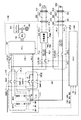
図1は、本実施の形態に従うECU300が搭載されたハイブリッド車両100の全体構ブロック図である。
FIG. 1 is an overall structural block diagram of
図1を参照して、車両100は、蓄電装置110と、システムメインリレー(以下、SMR(System Main Relay)とも称する。)115と、負荷装置170と、制御装置(以下、ECU(Electronic Control Unit)とも称する。)300とを備える。また、負荷装置170は、PCU(Power Control Unit)120と、モータジェネレータ130と、動力伝達ギア140と、駆動輪150と、エンジン160とを含む。
Referring to FIG. 1,
蓄電装置110は、充放電可能に構成された電力貯蔵要素である。本実施の形態においては、蓄電装置110は、負荷装置170に対して並列に接続された電池パックBP1,BP2を含む。電池パックBP1,BP2の各々は、たとえば、リチウムイオン電池、ニッケル水素電池または鉛蓄電池などの二次電池、あるいは電気二重層キャパシタなどの蓄電素子のセルを含んで構成され、これらの複数のセルが積層されることによって所望の電圧が出力される。
The
蓄電装置110は、さらに、電池パックBP1,BP2の各々に流れる電流を検出するための電流センサ111,112と、電池パックBP1,BP2に流れるトータルの電流を検出するための電流センサ113とを含む。これらの電流センサによって検出された電流値IB0,IB1,IB2は、ECU300へ出力される。また、蓄電装置110には、電池パックBP1,BP2の各々の電圧を検出するための電圧センサ(図示せず)がさらに設けられ、検出された電圧VB1,VB2はECU300へ出力される。ECU300においては、これらの電流IB0,IB1,IB2および電圧VB1,VB2の検出値に基づいて、蓄電装置110の充電状態SOC(State of Charge)を演算する。
蓄電装置110は、SMR115を介して、モータジェネレータ130を駆動するためのPCU120に接続される。そして、蓄電装置110は、車両100の駆動力を発生させるための電力をPCU120に供給する。また、蓄電装置110は、モータジェネレータ130で発電された電力を蓄電する。蓄電装置110の出力は、たとえば200Vである。
SMR115は、複数のリレーSMR−11,SMR−12,SMR−2,SMR−Gを含む。SMR−11の一方端は電池パックBP1の正極端子に接続され、他方端はPCU120に接続された電力線PL1に接続される。SMR−12の一方端は電池パックBP2の正極端子に接続され、他方端はPCU120に接続された電力線PL1に接続される。SMR−Gの一方端は、並列に接続された電池パックBP1,BP2の負極側の接続ノードNPに接続され、他方端はPCU120に接続された接地線NL1に接続される。抵抗R1に直列接続されたSMR−2は、SMR−Gに並列に接続される。SMR−2は、蓄電装置110からPCU120への電力供給開始時の突入電流の低減、あるいは電力遮断時のSMR−Gの溶着防止のためのリレーである。SMR115に含まれるこれらのリレーは、ECU300からの制御信号SE1に基づいて制御され、蓄電装置110とPCU120との間での電力の供給と遮断とを切換える。
The
PCU120は、いずれも図示しないが、蓄電装置110から供給される直流電圧を所定の電圧に昇圧するためのコンバータ、およびコンバータから出力される直流電力を交流電力に変換してモータジェネレータ130を駆動するためのインバータなどを含む。コンバータおよびインバータは、ECU300からの制御信号PWC,PWIに従ってそれぞれ制御される。
Although not shown,
モータジェネレータ130は交流回転電機であり、たとえば、永久磁石が埋設されたロータを備える永久磁石型同期電動機である。
モータジェネレータ130の出力トルクは、減速機や動力分割機構によって構成される動力伝達ギア140を介して駆動輪150に伝達されて、車両100を走行させる。モータジェネレータ130は、車両100の回生制動動作時には、駆動輪150の回転力によって発電することができる。そして、その発電電力は、PCU120によって蓄電装置110の充電電力に変換される。
The output torque of
モータジェネレータ130は、動力伝達ギア140を介してさらにエンジン160とも接続される。車両100が、モータジェネレータ130およびエンジン160からの駆動力を利用して、SOCを所定の値に維持しながら走行するHV(Hybrid Vehicle)走行を行なうCS(Charge Sustaining)モードの場合には、ECU300によってモータジェネレータ130からの駆動力とエンジン160からの駆動力との割合が適切に調整され、合成された駆動力を用いて車両100の走行が実行される。モータジェネレータ130からの駆動力のみを用いて走行するEV(Electric Vehicle)走行を優先的に行なうCD(Charge Depleting)モード選択することも可能である。ECU300は、運転者の操作信号SELに基づいて、上記のCSモードおよびCDモードの切換えを実行する。
なお、本実施の形態においては、車両100に1つのモータジェネレータが設けられる構成を一例として示すが、モータジェネレータを複数備える構成としてもよい。たとえば、2つのモータジェネレータが備えられる場合には、一方のモータジェネレータを専ら駆動輪を駆動するための電動機として機能させ、他方のモータジェネレータを専らエンジンの駆動力により発電する発電機として機能させる構成としてもよい。
In the present embodiment, a configuration in which one motor generator is provided in
また、本実施の形態においては、車両100は、上述のように、ハイブリッド自動車を例として説明するが、車両100の構成は、車両駆動力を発生するための電動機を搭載する車両であればその構成は限定されない。車両100は、図1のような電気自動車のほかに、エンジンを搭載しない電気自動車あるいは燃料電池自動車などを含む。
In the present embodiment,
車両100は、外部交流電源400からの電力を用いて蓄電装置110を充電するための構成として、充電装置200と、充電リレーCHR_ACと、接続部210とをさらに備える。外部交流電源400としては、一般家庭の電源や充電専用の充電ステーションなどが考えられ、その電圧は、たとえば、100Vまたは200Vである。
接続部210は、外部交流電源400からの電力を受けるために、車両100のボディに設けられる。接続部210には、充電ケーブル250の充電コネクタ251が接続される。そして、充電ケーブル250の電源プラグ252が、外部交流電源400のコンセント410に接続されることによって、外部交流電源400からの電力が、充電ケーブル250の電線部253を介して車両100に伝達される。また、図示されないが、充電ケーブル250の電線部253には、外部交流電源400から車両100への電力の供給と遮断とを切換えるための、充電回路遮断装置(以下「CCID(Charging Circuit Interrupt Device)」とも称する。)が介挿される場合がある。
充電装置200は、電力線ACL1,ACL2を介して接続部210に接続される。また、充電装置200は、CHR_ACを介して蓄電装置110と接続される。そして、充電装置200は、ECU300からの制御信号PWDに基づいて、外部交流電源400から供給される交流電力を、蓄電装置110が充電可能な直流電力に変換する。
CHR_ACに含まれるリレーの一方端は、蓄電装置110の正極端子および負極端子にそれぞれ接続される。CHR_ACに含まれるリレーの他方端は、充電装置200に接続された電力線PL2および接地線NL2にそれぞれ接続される。そして、CHR_ACは、ECU300からの制御信号SE2に基づいて、充電装置200から蓄電装置110への電力の供給と遮断とを切換える。
One end of the relay included in CHR_AC is connected to the positive terminal and the negative terminal of
車両100は、上記の外部交流電源400を用いた外部充電よりも短時間で蓄電装置110の充電を行なう急速充電のための構成として、充電リレーCHR_DCと、接続部220とをさらに有する。
接続部220は、外部直流電源500からの電力を受けるために、車両100のボディに設けられる。接続部220には、充電ケーブル260の充電コネクタ261が接続される。そして、充電ケーブル260の電源プラグ262が、外部直流電源500のコンセント510に接続されることによって、外部直流電源500からの電力が、充電ケーブル260の電線部263を介して車両100に伝達される。
充電リレーCHR_DCに含まれる一方のリレーは、その一方端が電源線PL3を介して接続部220に接続され、他方端が電力線PL1に接続される。充電リレーCHR_DCに含まれる他方のリレーは、その一方端が接地線NL3を介して接続部220に接続され、他方端が蓄電装置110の接続ノードNPに接続される。充電リレーCHR_DCは、ECU300からの制御信号SE3に基づいて、外部直流電源500から蓄電装置110への電力の供給と遮断とを切換える。
One relay included in charging relay CHR_DC has one end connected to
急速充電の場合に流れる充電電流ICH_DCの大きさは、外部交流電源400を用いた外部充電の場合に流れる充電電流ICH_ACの大きさよりも大きく、たとえば、ICH_ACが10A〜20Aであるのに対して、ICH_DCは50〜100Aに設定される。
The magnitude of the charging current ICH_DC that flows in the case of rapid charging is larger than the magnitude of the charging current ICH_AC that flows in the case of external charging using the external
外部直流電源500の電圧は、図1の構成においては、蓄電装置110の電圧とほぼ同じであり、たとえば200Vである。そのため、外部直流電源500から蓄電装置110までの間には電力変換装置は必要とされず、外部直流電源500からの電力は、いくつかのリレーを介して直接的に蓄電装置110へ供給される。
The voltage of external
なお、外部直流電源500の電圧は、必ずしも蓄電装置110の電圧とほぼ同じとする必要はなく、蓄電装置110の電圧よりも大きくまたは小さくするようにしてもよい。また、直流でなくとも、外部交流電源400よりも大きな電流が供給可能な交流電源とすることもできる。しかしながら、そのような場合には、外部電源から蓄電装置110までの経路に電力変換装置(DC/DC変換器、または、AC/DC変換器)が必要となるが、供給される電流が大電流であるために、それに耐え得る電流容量を有した電力変換装置が必要となるのでコスト増加の要因になり得る。さらに、電力変換動作によって、効率の低下にもつながる。そのため、図1のように、蓄電装置110の電圧とほぼ同じ電圧を供給可能な直流電源を蓄電装置110と直接的に接続する構成とすることがより望ましい。
Note that the voltage of external
ECU300は、いずれも図1には図示しないがCPU(Central Processing Unit)、記憶装置および入出力バッファなどを含み、各センサ等からの信号の入力および各機器への制御信号の出力を行なうとともに、車両100および各機器の制御を行なう。なお、これらの制御については、ソフトウェアによる処理に限られず、専用のハードウェア(電子回路)で処理することも可能である。なお、図1ではECU300は1つの制御装置として示されているが、各機器または機能ごとに個別の制御装置を設ける構成としてもよい。
ECU300は、運転者によるイグニッションスイッチの操作に関する操作信号IGを受ける。ECU300は、操作信号IGに基づいて、車両100の走行のための各種の制御を開始する。
図1に示されるような車両においては、走行時、外部交流電源400を用いた外部充電時、および外部直流電源500を用いた外部充電時の各々の場合で、流れる電流の電流経路が異なる。そして、上記の各場合において流れる電流の大きさも異なるので、各電流経路に備えられる部品については、そこに流れる電流の大きさに対応した耐熱保護が必要とされる。
In the vehicle as shown in FIG. 1, the current path of the flowing current is different in each case of traveling, external charging using external
図2は、保護が必要とされる対象部品のグループについての、通電タイミングと参照すべき電流を説明するための図である。対象部品のグループは、電流経路に対応して大きく4つに分類される。 FIG. 2 is a diagram for explaining energization timing and a current to be referred to for a group of target parts that need to be protected. The group of target parts is roughly classified into four corresponding to the current paths.
第1のグループ(グループA)は、個々の電池パックに流れる電流に対する電流経路であり、図1においてGR_Aで示される。具体的な対象部品としては、電池パックBP1,BP2およびSMR−11,SMR−12が含まれる。グループAについては、走行時、外部交流電源400を用いた外部充電時、および外部直流電源500を用いた外部充電時のいずれの場合においても通電される。そして、このときに対象部品に流れる電流は、電流センサ111,112で検出された電流IB1,IB2である。
The first group (group A) is a current path for a current flowing through each battery pack, and is indicated by GR_A in FIG. Specific target parts include battery packs BP1 and BP2 and SMR-11 and SMR-12. The group A is energized in any of the cases of traveling, external charging using the external
第2のグループ(グループB)は、電池パックBP1,BP2からの経路が合流した部分であり、図1においてはGR_Bで示される。グループBもグループAと同様に、走行時および交流,直流いずれの外部充電時にも電流が流れるが、流れる電流の大きさはグループAよりも大きく、電流センサ113で検出される電流IB0(すなわち、IB1+IB2)である。 The second group (group B) is a portion where the paths from the battery packs BP1 and BP2 merge and is indicated by GR_B in FIG. In the group B as well as the group A, current flows during traveling and external charging of both AC and DC, but the magnitude of the flowing current is larger than that of the group A, and the current IB0 detected by the current sensor 113 (that is, IB1 + IB2).
第3のグループ(グループC)は、外部直流電源500を用いた外部充電時、すなわち急速充電時にのみ電流が流れる経路であり、図1においてはGR_Cで示される。具体的な部品としては、急速充電用の充電リレーCHR_DCおよびそれに接続されるケーブル等が含まれる。
The third group (group C) is a path through which current flows only during external charging using the external
第4のグループ(グループD)は、走行時および外部交流電源400を用いた外部充電時にのみ電流が流れる経路であり、図1においてはGR_Dで示される。このグループにおける具体的な部品は、SMR−2,SMR−Gが含まれる。このうち、SMR−2は抵抗R1と直列接続されているため、SMR−Gに比べると流れる電流は少なくなる。したがって、グループDにおいては、特にSMR−Gの耐熱保護が必要となる。
The fourth group (group D) is a path through which current flows only during traveling and during external charging using the external
なお、グループCおよびグループDにおいて参照される電流は、グループBと同様に電流センサ113で検出される電流IB0である。
The current referred to in group C and group D is current IB0 detected by
上述のように、急速充電の場合には、走行時および外部交流電源400を用いた外部充電時に流れる電流よりも大きい電流が充電電流として流れるので、本来的には、この急速充電時の充電電流による発熱に耐え得る保護が必要である。しかしながら、たとえば、図2におけるグループAおよびグループBのように、走行時、および、いずれの外部充電時にも電流が流れる電流経路について、急速充電に対応可能な保護レベルの部品を使用すると、急速充電以外の動作の場合にはオーバースペックとなり、コストアップの要因となり得る。
As described above, in the case of rapid charging, a current larger than the current flowing during running and external charging using the external
一方、急速充電に対応可能な保護レベルよりも低い保護レベルの部品を用いつつ、急速充電においてもその低い保護レベルで部品を保護できるように、一律に電流を制限する手法も可能であるが、かえって急速充電時以外の場合の動作の性能低下や、充電時間の延長などの問題を招くおそれがある。 On the other hand, while using parts with a protection level lower than the protection level that can handle fast charging, a method of uniformly limiting the current is also possible so that parts can be protected at that low protection level even during fast charging. On the contrary, there is a risk of causing problems such as a decrease in performance in cases other than rapid charging, and an increase in charging time.
そのため、本実施の形態においては、各部品に流れる電流と通電時間とに基づいて各部品の発熱状態を表わす評価関数を用いるとともに、その評価関数の出力値に基づいて蓄電装置への充放電電力の制限値を修正することによって各部品に流れる電流を制限する手法を採用する。このような構成にすることによって、各時点において、部品ごとの発熱状態に対応して部品に流れる電流を制御することができるので、過剰な部品保護による車両の動力性能の低下を抑制しつつ、適切に部品を保護することが可能となる。 Therefore, in the present embodiment, an evaluation function representing the heat generation state of each component is used based on the current flowing through each component and the energization time, and the charge / discharge power to the power storage device is determined based on the output value of the evaluation function. A method is adopted in which the current flowing through each component is limited by correcting the limit value. By adopting such a configuration, it is possible to control the current flowing through the component corresponding to the heat generation state of each component at each time point, while suppressing a decrease in the power performance of the vehicle due to excessive component protection, It becomes possible to protect the parts appropriately.
一般的に、部品の発熱は、部品を流れる電流値の二乗に比例することが知られており、また、部品からの放熱については、一次遅れ系で近似できることが知られている。この関係を評価関数Fとして表わすと、たとえば式(1)のようになる。
F(n+1)={(K(n)−1)×F(n)+I(n)2}/K(n) … (1)
ここで、nは制御開始からの制御周期の回数、すなわち経過時間を表わす。また、I(n)は制御周期回数nのときの部品に流れる電流値を表わし、K(n)は一次遅れ近似を行なうための係数、すなわち時定数に相当する係数である。この係数K(n)は、部品ごとに異なる値を有しており、予め実験等によって定められたマップ等によって設定される。また、係数K(n)は、電流の増加時および減少時によって、異なる値を持つようにしてもよい。
In general, it is known that the heat generation of a component is proportional to the square of the current value flowing through the component, and it is known that the heat radiation from the component can be approximated by a first-order lag system. When this relationship is expressed as an evaluation function F, for example, the following equation (1) is obtained.
F (n + 1) = {(K (n) −1) × F (n) + I (n) 2 } / K (n) (1)
Here, n represents the number of control cycles from the start of control, that is, the elapsed time. Further, I (n) represents the value of the current flowing through the component at the control cycle number n, and K (n) is a coefficient for performing first-order delay approximation, that is, a coefficient corresponding to a time constant. The coefficient K (n) has a different value for each part, and is set by a map or the like determined in advance through experiments or the like. The coefficient K (n) may have different values depending on when the current increases and decreases.
図3は、ある部品について電流を流した場合の、部品温度の時間的変化の一例を示した図である。図3においては、時刻t0のとき初期温度T0であった部品に、時刻t0からt1の間、電流を流した場合の図である。 FIG. 3 is a diagram showing an example of a temporal change in component temperature when a current is passed through a certain component. In FIG. 3, it is a figure at the time of flowing an electric current from the time t0 to t1 to the components which were the initial temperature T0 at the time t0.
図3に示されるように、通電開始後、時間とともに部品の温度は、時間に対してほぼ一次遅れの曲線で上昇する。そして、時刻t1で通電を停止すると、それ以降は、時刻t1における温度を初期値として、一次遅れ系の曲線で部品温度が低下する。 As shown in FIG. 3, after the start of energization, the temperature of the component rises with a curve that is almost linearly delayed with respect to time. Then, when the energization is stopped at time t1, the temperature of the component is reduced by a first-order lag curve with the temperature at time t1 as an initial value thereafter.
また、図3には、部品に流れる電流を変化させた場合の曲線が曲線W1からW4で示されるが、電流Iが大きくなるほど部品温度が高くなっており、電流Iの二乗値(I2)に比例して大きくなる。 Also, in FIG. 3, curves when the current flowing through the component is changed are indicated by curves W1 to W4. As the current I increases, the component temperature increases, and the square value (I 2 ) of the current I increases. Increases in proportion to
保護対象となる部品に対して、実験によって、図3に示されたような曲線をそれぞれ求め、その曲線に適合するように式(1)の評価関数Fの係数Kを定める。これにより、通電電流と通電時間とに基づいて部品の発熱を推定することができる。そして、各部品に対して、評価関数の出力値が当該部品の耐熱限界にから定まるしきい値を超えないように電流を調整することで、部品の発熱を制御することができる。 With respect to the parts to be protected, curves such as those shown in FIG. 3 are obtained by experiments, and the coefficient K of the evaluation function F of Equation (1) is determined so as to fit the curves. Thereby, the heat_generation | fever of components can be estimated based on an energization current and energization time. For each component, the heat generation of the component can be controlled by adjusting the current so that the output value of the evaluation function does not exceed the threshold value determined from the heat resistance limit of the component.
図4は、本実施の形態における、充放電電力制限値の修正制御の概要を説明するための図である。図4においては、横軸に時間が示され、縦軸にはある電流経路の部品についての評価関数の出力値、蓄電装置の充放電電力制限値Win,Wout、および当該部品の温度が示される。なお、本実施の形態においては、充放電電力については、放電電力を正値で表わし、充電電力を負値で表わすものとする。 FIG. 4 is a diagram for explaining the outline of the correction control of the charge / discharge power limit value in the present embodiment. In FIG. 4, the horizontal axis indicates time, and the vertical axis indicates the output value of the evaluation function for the component of a certain current path, the charge / discharge power limit values Win and Wout of the power storage device, and the temperature of the component. . In the present embodiment, with regard to charge / discharge power, discharge power is represented by a positive value, and charge power is represented by a negative value.
図4を参照して、時刻t20から部品への通電を開始すると、時間とともに徐々に部品温度が上昇する。また、当該部品についての評価関数Fの出力値も、部品温度に対応して、同じように増加する。時刻t20から時刻t21までの間の充放電電力制限値Win,Woutは、蓄電装置110のSOCに基づいて定められる制限値Swin,Swoutに設定される。
Referring to FIG. 4, when energization of a component is started from time t20, the component temperature gradually increases with time. In addition, the output value of the evaluation function F for the part also increases correspondingly with the part temperature. Charge / discharge power limit values Win, Wout between time t20 and time t21 are set to limit values Swin, Swout determined based on the SOC of
そして、評価関数Fの出力値がしきい値TH1となる時刻t21となったところで、充電電力がさらに制限されるように、充電電力制限値Winの値がMwinに修正される。なお、上述のように、充電電力は負値で表わされているため、「充電電力が制限される」とは、その大きさ、すなわち絶対値が小さくされることを意味する(すなわち、|Swin|>|Mwin|)。これにより、図4に示す動作が外部充電である場合には、たとえば、充電装置200の出力を低減したり、または充電リレーCHR_AC,CHR_DCを間欠的に遮断したりすることによって、充電電力が制限される。その結果、部品に流れる電流が低減され、部品の発熱を抑制することができる。
Then, at time t21 when the output value of the evaluation function F becomes the threshold value TH1, the value of the charging power limit value Win is corrected to Mwin so that the charging power is further limited. As described above, since the charging power is represented by a negative value, “the charging power is limited” means that the magnitude, that is, the absolute value is reduced (that is, | Swin |> | Mwin |). Thereby, when the operation shown in FIG. 4 is external charging, the charging power is limited by, for example, reducing the output of the
また、走行時においても、たとえば長い下り坂が継続するような場合には、モータジェネレータ130による回生制動によって発電された充電電力が長時間回路に流れることが考えられる。このような場合においても、評価関数の出力値が上記のしきい値TH1を上回るときには、PCU120内のコンバータやインバータなどの電力変換装置の効率を低下させる等の処理によって、該当部品への電流を低減するようにしてもよい。
Further, even during traveling, for example, when a long downhill continues, it is conceivable that the charging power generated by the regenerative braking by the
次に、評価関数Fの出力値がしきい値TH2となる時刻t22となると、放電電力制限値Woutの値がMwoutに修正される。これによって、図4に示す動作が走行時の場合には、制限された放電電力制限値に基づいて、PCU120に供給される電力が設定(低減)されるので、部品の発熱が抑制される。
Next, at time t22 when the output value of the evaluation function F reaches the threshold value TH2, the value of the discharge power limit value Wout is corrected to Mwout. Accordingly, when the operation shown in FIG. 4 is during travel, the power supplied to the
このようにして、制限された充放電電力制限値Win,Woutに基づいて、充電動作または放電動作が行なわれるので、時刻t22から時刻t23までは部品温度の上昇が抑制される。その後、通電が停止され、評価関数の出力値がしきい値を下回ると、それに応じて充放電電力制限値Win,Woutが、SOCに基づいて定められる制限値Swin,Swoutに戻される。 In this way, since the charging operation or the discharging operation is performed based on the limited charge / discharge power limit values Win and Wout, an increase in the component temperature is suppressed from time t22 to time t23. Thereafter, when the energization is stopped and the output value of the evaluation function falls below the threshold value, the charge / discharge power limit values Win and Wout are returned to the limit values Swin and Swout determined based on the SOC accordingly.
なお、図4においては、充電電力制限値Winについてのしきい値TH1が、放電電力制限値Woutについてのしきい値TH2より小さく設定(TH1<TH2)されているが、これは一例であって、部品に応じて、充電電力制限値Winについてのしきい値TH1が、放電電力制限値Woutについてのしきい値TH2より大きく設定されるようにしてもよい。 In FIG. 4, the threshold value TH1 for the charging power limit value Win is set smaller than the threshold value TH2 for the discharging power limit value Wout (TH1 <TH2), but this is an example. Depending on the component, the threshold value TH1 for the charging power limit value Win may be set larger than the threshold value TH2 for the discharging power limit value Wout.
また、図1に示したハイブリッド車両では、上述のように、モータジェネレータ130からの駆動力のみを優先的に用いて走行するCDモードと、モータジェネレータ130およびエンジン160からの駆動力を利用して走行するCSモードとを有する場合がある。
In the hybrid vehicle shown in FIG. 1, as described above, the CD mode in which only the driving force from
図5に、CDモードでの走行時とCSモードでの走行時のSOCの変化の一例を示すが、一般的に、CDモードでは、エンジン160からの駆動力を用いないために、CSモードでの走行に比べてSOCの変化量が大きい。すなわち、蓄電装置110から入出力される電流が、CDモードのほうがCSモードよりも大きく、かつ長時間流れることになる。したがって、電流経路の部品に対する影響は、CSモードの走行よりもCDモードでの走行のほうが大きくなる場合がある。そのため、そのような部品に対しては、同じ部品であっても、CDモードであるかCSモードであるかによって、異なった評価関数Fを用いることが好ましい。
FIG. 5 shows an example of the change in the SOC when traveling in the CD mode and when traveling in the CS mode. In general, in the CD mode, the driving force from the
さらに、たとえば、部品への通電を停止した直後に、その部品への通電を再開したような場合には、通電再開時には、部品の温度がまだ十分に低下していないことが考えられる。そのような場合には、通電電流の大きさおよび通電時間が同じであっても、部品の温度が十分に低下している場合と比較して部品の温度が高くなり、適切に保護できない場合が起こり得る。そのため、本実施の形態においては、さらに、部品への通電を停止してからの時間に基づいて、評価関数の初期値を変更する。 Furthermore, for example, when energization of a component is resumed immediately after the energization of the component is stopped, it is conceivable that the temperature of the component has not yet sufficiently decreased when energization is resumed. In such a case, even if the energizing current and energizing time are the same, the temperature of the component may be higher than when the temperature of the component is sufficiently lowered and may not be properly protected. Can happen. Therefore, in the present embodiment, the initial value of the evaluation function is further changed based on the time after the energization of the parts is stopped.
図6は、本実施の形態における、評価関数の初期値の設定手法を説明するための図である。 FIG. 6 is a diagram for explaining a method for setting an initial value of an evaluation function in the present embodiment.
図6を参照して、時刻t31までは、走行または外部充電が実行されており、通電によりある部品の温度が上昇した状態である場合を考える。そして、時刻t31において、イグニッションがオフとされ、あるいは充電動作が停止されることによって、当該部品への通電が停止すると、部品の温度は、図6中における破線の曲線W30のように低下する。 Referring to FIG. 6, a case is considered in which traveling or external charging is being executed and the temperature of a certain component is increased by energization until time t31. Then, at time t31, when the ignition is turned off or the charging operation is stopped to stop energization of the part, the temperature of the part decreases as indicated by a broken line W30 in FIG.
ここで、時刻t32において部品への通電が再開されると、その時点においては、部品温度は十分に低下しておらず、T1の温度を有している。そうすると、時刻t32から通電を再開した場合には、部品温度は図6における曲線W31のように変化する。 Here, when energization of the component is resumed at time t32, at that time, the component temperature is not sufficiently lowered and has a temperature of T1. Then, when energization is resumed from time t32, the component temperature changes as shown by a curve W31 in FIG.
一方で、時刻t32よりも時間が経過した時刻t33において部品の通電が再開された場合には、部品温度はT2(T2<T1)の温度を有しており、この場合には、部品温度は図6における曲線W32のように変化する。 On the other hand, when energization of the component is resumed at time t33 when time has elapsed from time t32, the component temperature has a temperature of T2 (T2 <T1). In this case, the component temperature is It changes like a curve W32 in FIG.
そのため、図3において説明したように、通電停止後の部品温度についての評価関数に基づいて、通電停止から通電再開までの時間に応じて、通電時の評価関数の初期値を設定する。これによって、通電時の評価関数を図6における曲線W31およびW32に適合させることができ、これによって、通電の停止と再開とを繰り返したような場合であっても、適切に部品温度を評価して保護することが可能となる。 Therefore, as described in FIG. 3, the initial value of the evaluation function at the time of energization is set according to the time from the energization stop to the energization restart based on the evaluation function for the component temperature after the energization is stopped. As a result, the evaluation function at the time of energization can be adapted to the curves W31 and W32 in FIG. 6, and accordingly, even when the energization is stopped and restarted, the component temperature is appropriately evaluated. Can be protected.
図7は、本実施の形態において、ECU300で実行される充放電電力制限値の修正制御を説明するための機能ブロック図である。図7で説明されるブロック図に記載された各機能ブロックは、ハードウェア的あるいはソフトウェア的な処理によって実現される。
FIG. 7 is a functional block diagram for illustrating correction control of the charge / discharge power limit value executed by
図1および図7を参照して、ECU300は、電流検出部310と、モード選択部320と、停止時間判定部330と、評価関数生成部340と、Mwin/Mwout演算部350と、修正部360と、Win/Wout設定部365と、駆動制御部370と、記憶部380とを含む。また、駆動制御部370は、充電制御部371と、PCU制御部372とを含む。
Referring to FIGS. 1 and 7,
電流検出部310は、電流センサ111〜113の検出値IB0〜IB2を受ける。そして、電流検出部310は、受信した電流検出値をMwin/Mwout演算部350へ出力する。
モード選択部320は、運転者の操作によるCSモードおよびCDモードのいずれかの選択を示す操作信号SELを受ける。そして、モード選択部320は、操作信号SELに基づいてCSモードまたはCDモードを選択し、その選択結果であるモード信号MODを評価関数生成部340へ出力する。
The
停止時間判定部330は、運転者による車両100の運転動作を示すイグニッションスイッチの操作信号IGと、図示しない上位ECUまたは外部電源から、外部充電実行中であることを示す充電信号CHGとを受ける。停止時間判定部330は、これらの信号に基づいて、上述のように、評価関数の初期値を決定するために必要な、走行および外部充電における通電が停止してからの時間を演算する。そして、停止時間判定部330は、その停止時間TIMを評価関数生成部340へ出力する。また、停止時間判定部330は、現在車両100が走行中であるか、あるいは、外部交流電源400を用いた外部充電であるかまたは外部直流電源500を用いた外部充電であるかの車両状態を判定し、その状態信号STATを評価関数生成部340へ出力する。
Stop
評価関数生成部340は、モード選択部320からのモード信号MODと、停止時間判定部330からの停止時間TIMおよび車両の状態信号STATとを受ける。
Evaluation
評価関数生成部340は、車両の状態信号STATおよびモード信号MODに基づいて、各部品についての評価関数が予め記憶された記憶部380から、保護対象となる各部品についての評価関数を生成する。評価関数生成部340は、停止時間TIMから生成した各部品についての評価関数における初期値を決定する。そして、評価関数生成部340は、生成した評価関数FnをMwin/Mwout演算部350へ出力する。
Based on the vehicle state signal STAT and the mode signal MOD, the evaluation
Mwin/Mwout演算部350は、電流検出部310からの電流検出値IB0〜IB2を、評価関数生成部340からの評価関数Fnへ適用して、各部品についての耐熱保護から定まる充放電電力制限値Mwin/Mwoutを演算により求める。そして、その演算結果MW(n)を修正部360へ出力する。
The Mwin /
Win/Wout設定部365は、蓄電装置110のSOCを受ける。そして、Win/Wout設定部365は、SOCに基づいて定まる充放電電力制限値Swin/Swoutを演算し、その演算結果を充放電電力制限値の初期値Win#/Wout#として修正部360へ出力する。
Win / Wout setting unit 365 receives the SOC of
修正部360は、Mwin/Mwout演算部350からの各部品についての充放電電力制限値MW(n)と、Win/Wout設定部365からの充放電電力制限値の初期値Win#/Wout#とを受ける。
The
修正部360は、各部品についての充放電電力制限値MW(n)のうち、充電電力制限値Mwinおよび放電電力制限値Mwoutのそれぞれについて、各制限値の大きさ(すなわち、絶対値)が最小となる値を決定する。修正部360は、充電電力制限値Mwinおよび放電電力制限値Mwoutについての各最小値と、充放電電力制限値の初期値Win#/Wout#とをさらに比較して、より大きさが小さくなる制限値を充放電電力制限値Win/Woutに設定する。そして、修正部360は、最終的に設定された充放電電力制限値Win/Woutを駆動制御部370(すなわち、充電制御部371およびPCU制御部372)へ出力する。
The
充電制御部371は、修正部360からの充放電電力制限値Win/Woutを受ける。充電制御部371は、外部充電が行なわれる場合に、充放電電力制限値Win/WoutとSOCとに基づいて、充電装置200および充電リレーCHR_AC,CHR_DCを制御するための制御信号PWD,SE2,SE3を生成する。充電制御部371は、これらの制御信号を、充電装置200および充電リレーCHR_AC,CHR_DCにそれぞれ出力して、外部充電を実行する。
PCU制御部372は、修正部360からの充放電電力制限値Win/Woutと、運転者の運転動作に基づくトルク指令値および回転速度指令値とに基づいて、PCU120内のコンバータおよびインバータの制御信号PWC,PWIを生成する。PCU制御部372は、これらの制御信号をPCU120へ出力して車両の駆動力を制御する。
The
図8は、本実施の形態の充放電電力制限値の修正制御において、ECU300で実行される各対象部品についての充放電電力制限値Mwin/Mwoutの演算処理を説明するためのフローチャートである。図8および後述する図9に示すフローチャート中の各ステップについては、ECU300に予め格納されたプログラムのメインルーチンから呼び出されて所定周期で実行することによって実現される。あるいは、一部のステップについては、専用のハードウェア(電子回路)を構築して処理を実現することも可能である。
FIG. 8 is a flowchart for illustrating a calculation process of charge / discharge power limit values Mwin / Mwout for each target component executed by
図1および図8を参照して、ECU300は、ステップ(以下、ステップをSと略す。)10にて、対象部品についての評価関数の初期値がすでに決定されているか否かを判定する。
Referring to FIGS. 1 and 8,
評価関数の初期値が未決定の場合(S10にてNO)は、処理がS20に進められて、ECU300は、図6で説明したように、通電停止からの時間に基づいて評価関数の初期値を決定する。その後、処理がS30に進められる。
If the initial value of the evaluation function has not been determined (NO in S10), the process proceeds to S20, and
一方、評価関数の初期値がすでに決定されている場合(S10にてYES)は、S20がスキップされて、処理がS30に進められる。 On the other hand, when the initial value of the evaluation function has already been determined (YES in S10), S20 is skipped and the process proceeds to S30.
S30では、ECU300は、初期値に基づいて、対象部品についての評価関数を生成する。
In S30,
そして、S40にて、ECU300は、対象部品について、図2で説明した参照電流を用いて評価関数の出力値を演算し、その演算結果としきい値との比較に基づいて、充放電電力制限値Mwin/Mwoutを演算する。
In S40,
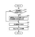
図9は、本実施の形態において、ECU300で実行される充放電電力制限値の修正制御処理の全体を説明するためのフローチャートである。
FIG. 9 is a flowchart for illustrating the entire charge / discharge power limit correction control process executed by
図1および図9を参照して、ECU300は、S100にて車両100が現在走行中であるか否かを判定する。
Referring to FIGS. 1 and 9,
車両100が現在走行中の場合(S100にてYES)は、S110に処理が進められ、ECU300は、次に走行モードがCDモードであるか否かを判定する。
If
走行モードがCDモードである場合(S110にてYES)は、処理がS120に進められ、ECU300は、評価関数としてCDモード用の評価関数を選択する。
If the running mode is the CD mode (YES in S110), the process proceeds to S120, and
一方、走行モードがCDモードでない場合、すなわちCSモードの場合(S110にてNO)は、処理がS125に進められ、ECU300は、CSモード用の評価関数を選択する。
On the other hand, when the travel mode is not the CD mode, that is, in the CS mode (NO in S110), the process proceeds to S125, and
そして、ECU300は、S130にて、図2のグループDのSMR−Gについて、選択された評価関数に参照電流の電流検出値を適用して、図8で説明した処理に従って充放電電力制限値Mwin/Mwout(MW(1))を演算する。
Then, in S130,
ECU300は、次にS140にて、図2のグループAの電池パックラインについて、選択された評価関数に参照電流の電流検出値を適用して、図8で説明した処理に従って充放電電力制限値Mwin/Mwout(MW(2))を演算する。
Next, in S140,
ECU300は、S150にて、図2のグループBの合流部ラインについて、選択された評価関数に参照電流の電流検出値を適用して、図8で説明した処理に従って充放電電力制限値Mwin/Mwout(MW(3))を演算する。
In S150,
そして、ECU300は、S160にて、上記で算出された、各グループの充放電電力制限値を比較して、充電電力制限値Mwinおよび放電電力制限値Mwoutの大きさの最小をそれぞれ演算する。なお、走行時においては、グループCの急速充電ラインの充放電電力制限値Mwin/Mwout(MW(4))が演算されていないが、演算されていない充放電電力制限値Mwin/Mwoutについては、たとえば、SOCから定まる充放電電力制限値、あるいは十分に大きな値をデフォルト値として設定するようにしてもよい。
In S160,
その後、ECU300は、S170にて、SOCから定まる充放電電力制限値Swin/Swoutと、S160で算出した、対象部品の耐熱保護から定められる充放電電力制限値Mwin/Mwoutとを比較する。そして、ECU300は、対象部品の耐熱保護から定められた充放電電力制限値Mwin/Mwoutの大きさが、SOCから定まる充放電電力制限値Swin/Swoutの大きさよりも小さい場合には、充放電電力制限値Mwin/Mwoutにより充放電電力制限値Win/Woutを修正する。
Thereafter, in S170,
一方、走行中でない場合(S100にてNO)は、処理がS115に進められ、ECU300は、外部充電中であるか否かを次に判定する。
On the other hand, when the vehicle is not traveling (NO in S100), the process proceeds to S115, and
外部充電中でない場合(S115にてNO)は、走行も外部充電も行なわれておらず、通電されていないので、ECU300はメインルーチンに処理を戻す。
If external charging is not in progress (NO in S115), neither traveling nor external charging is performed and power is not supplied, and
外部充電中の場合(S115にてYES)は、処理がS116に進められて、ECU300は、外部直流電源500を用いた急速充電中であるか否かを判定する。
If external charging is in progress (YES in S115), the process proceeds to S116, and
急速充電中の場合(S116にてYES)は、処理がS117に進められ、ECU300は、図2のグループCの急速充電ラインについて、選択された評価関数に参照電流の電流検出値を適用して、図8で説明した処理に従って充放電電力制限値Mwin/Mwout(MW(4))を演算する。そして、ECU300は、処理をS140に進める。
If rapid charging is in progress (YES in S116), the process proceeds to S117, and
急速充電中でない場合(S116にてNO)は、外部交流電源400を用いた充電であるので、処理がS130に進められて、ECU300は、図2のグループDのSMR−Gについて、充放電電力制限値Mwin/Mwout(MW(1))を演算する。そして、処理がS140に進められる。
If rapid charging is not in progress (NO in S116), charging is performed using external
S140以降の処理は、上述と同様であり、ECU300は、S140およびS150にて、電池パックラインおよび合流部ラインの充放電電力制限値MW(2)、MW(3)をそれぞれ演算し、S160にて演算された対象部品ごとの充放電電力制限値を比較して、修正値の充放電電力制限値を演算する。そして、S170にて、ECU300は、この修正値とSOCから定まる充放電電力制限値Swin/Swoutとを比較して、充放電電力制限値Win/Woutを設定する。
The processes after S140 are the same as described above, and
以上のような処理に従って制御を行なうことによって、走行時および外部充電時において、評価関数を用いて各電流経路の部品についての発熱を逐次評価するとともに、最も耐熱保護が必要とされる部品が適切に保護されるように蓄電装置からの充放電電力を制限することができる。これによって、高い耐熱性能を有するが高価であるような部品を採用することなく、また過剰な耐熱保護による車両の動作性能の低下を抑制しつつ、各部品の耐熱保護を適切に行なうことが可能となる。 By performing the control according to the above processing, the heat generation of the components in each current path is sequentially evaluated using the evaluation function during traveling and external charging, and the components that require the most heat protection are appropriate. Thus, the charge / discharge power from the power storage device can be limited so as to be protected. As a result, it is possible to appropriately protect each component without using components that have high heat resistance but are expensive, and while suppressing deterioration in vehicle performance due to excessive heat protection. It becomes.
(変形例)
上述の図1に示した車両100では、急速充電の電流経路における負極側の配線部が、蓄電装置に直接接続される構成の例を示した。
(Modification)
In the
しかしながら、車両の構成によっては、たとえば、蓄電装置が車両後部のトランクや後部座席下部などに配置され、それ以外の機器が車両前部のボンネット内に配置される場合がある。このような場合に、図1の構成では、急速充電用の配線部を車両前部から蓄電装置の位置まで延長することが必要となる。ところが、急速充電の場合には上述のように比較的大きな電流が流れるため、配線部の導体の断面積も大きくなり得る。そうすると、配線部の長さが長くなるほど重量およびコストが増加するとともに、さらに取り付け作業において曲げ等の加工が困難となり、作業効率の低下を招くおそれがある。 However, depending on the configuration of the vehicle, for example, the power storage device may be disposed in the trunk at the rear of the vehicle, the lower part of the rear seat, or the like, and other devices may be disposed in the hood at the front of the vehicle. In such a case, in the configuration of FIG. 1, it is necessary to extend the rapid charging wiring portion from the front portion of the vehicle to the position of the power storage device. However, in the case of rapid charging, since a relatively large current flows as described above, the cross-sectional area of the conductor of the wiring portion can also be increased. Then, as the length of the wiring portion becomes longer, the weight and cost increase, and further, processing such as bending becomes difficult in the mounting operation, and work efficiency may be reduced.
そのため、図10の車両100Aに示すように、急速充電の負極側の配線部を、接地線NL1に接続することによって、配線部の長さを短縮化する構成が採用される場合がある。
Therefore, as shown in
このような構成の場合には、SMR−Gが含まれるグループDについても、急速充電時に電流が流れることになる。そのため、この場合には、SMR−Gについての評価関数を必要に応じて急速充電に対応したものに変更するとともに、図9のフローチャートにおいて、急速充電時にもS130の処理を実行するように変更することによって、上述と同様の制御が可能となる。 In the case of such a configuration, a current flows through the group D including the SMR-G at the time of quick charging. Therefore, in this case, the evaluation function for SMR-G is changed to one corresponding to rapid charging as necessary, and in the flowchart of FIG. 9, the processing of S130 is also changed during rapid charging. Thus, the same control as described above is possible.
なお、図1および図10以外の接続構成を有する場合においても、走行時および外部充電時の各電流経路に対応して、評価関数ならびにフローチャートを適宜変更することによって、本実施の形態を適用することが可能である。 Even in the case of connection configurations other than those shown in FIGS. 1 and 10, the present embodiment is applied by appropriately changing the evaluation function and the flowchart corresponding to each current path during traveling and during external charging. It is possible.
なお、本実施の形態においては、外部交流電源および外部直流電源の両方からの電力によって外部充電が可能な構成を例として説明したが、外部交流電源または外部直流電源のいずれか一方のみを備える構成についても、上述の手法を適用することが可能である。 In the present embodiment, the configuration in which external charging is possible with the power from both the external AC power source and the external DC power source has been described as an example, but the configuration having only one of the external AC power source and the external DC power source The above-described method can also be applied to.
今回開示された実施の形態はすべての点で例示であって制限的なものではないと考えられるべきである。本発明の範囲は上記した説明ではなく特許請求の範囲によって示され、特許請求の範囲と均等の意味および範囲内でのすべての変更が含まれることが意図される。 The embodiment disclosed this time should be considered as illustrative in all points and not restrictive. The scope of the present invention is defined by the terms of the claims, rather than the description above, and is intended to include any modifications within the scope and meaning equivalent to the terms of the claims.
100,100A 車両、110 蓄電装置、111,112,113 電流センサ、115 SMR、120 PCU、130 モータジェネレータ、140 動力伝達ギア、150 駆動輪、160 エンジン、170 負荷装置、200 充電装置、210,220 接続部、250,260 充電ケーブル、251,261 充電コネクタ、252,262 電源プラグ、253,263 電線部、300 ECU、310 電流検出部、320 モード選択部、330 停止時間判定部、340 評価関数生成部、350 Mwin/Mwout演算部、360 修正部、365 Win/Wout設定部、370 駆動制御部、371 充電制御部、372 PCU制御部、380 記憶部、400 外部交流電源、410,510 コンセント、500 外部直流電源、ACL1,ACL2,PL1〜PL3 電力線、BP1,BP2 電池パック、CHR_AC,CHR_DC 充電リレー、NL1〜NL3 接地線、NP 接続ノード、R1 抵抗、SMR−11,SMR−12,SMR−2,SMR−G リレー。 100, 100A Vehicle, 110 Power storage device, 111, 112, 113 Current sensor, 115 SMR, 120 PCU, 130 Motor generator, 140 Power transmission gear, 150 Drive wheel, 160 Engine, 170 Load device, 200 Charging device, 210, 220 Connection unit, 250, 260 Charging cable, 251, 261 Charging connector, 252, 262 Power plug, 253, 263 Electric wire unit, 300 ECU, 310 Current detection unit, 320 Mode selection unit, 330 Stop time determination unit, 340 Evaluation function generation Unit, 350 Mwin / Mwout calculation unit, 360 correction unit, 365 Win / Wout setting unit, 370 drive control unit, 371 charge control unit, 372 PCU control unit, 380 storage unit, 400 external AC power supply, 410, 510 outlet, 5 0 External DC power supply, ACL1, ACL2, PL1-PL3 power line, BP1, BP2 battery pack, CHR_AC, CHR_DC charging relay, NL1-NL3 ground line, NP connection node, R1 resistance, SMR-11, SMR-12, SMR-2 , SMR-G relay.
Claims (8)
前記蓄電装置に入出力される電流の少なくとも1つの電流経路にそれぞれ関連する少なくとも1つの部品に流れる電流に基づいて前記少なくとも1つの部品の温度に関連する情報を表わすような少なくとも1つの評価関数を生成するように構成された生成部と、
前記少なくとも1つの評価関数の出力値と予め定められたしきい値との比較に基づいて、前記蓄電装置に入出力可能な充放電電力の少なくとも1つの第1の制限値を演算するように構成された演算部と、
前記蓄電装置の充電状態に基づいて定められた前記蓄電装置に入出力可能な充放電電力の第2の制限値を、前記少なくとも1つの第1の制限値に基づいて修正するように構成された修正部と、
前記蓄電装置の充放電電力が、前記修正部により修正された前記第2の制限値の範囲内となるように、前記電気機器を駆動するための駆動制御部とを備え、
前記電気機器は、前記蓄電装置からの電力を用いて前記車両の駆動力を発生させるための回転電機と、エンジンとを含み、
前記車両は、前記エンジンおよび前記回転電機からの駆動力を利用して走行する第1の走行モードと、前記エンジンを停止して前記回転電機からの駆動力を利用した走行を優先的に行なう第2の走行モードとを選択的に切換えて走行することが可能であり、
前記生成部は、前記第1および第2の走行モードのうちの選択された走行モードに対応した前記少なくとも1つの評価関数を生成する、車両の制御装置。 A control device for a vehicle in which an electric device and a power storage device that supplies electric power for traveling are mounted and at least one of charging and discharging of the power storage device can be performed by the electric device,
At least one evaluation function representing information related to the temperature of the at least one component based on a current flowing in at least one component respectively associated with at least one current path of current input to and output from the power storage device; A generator configured to generate;
Based on a comparison between an output value of the at least one evaluation function and a predetermined threshold value, at least one first limit value of charge / discharge power that can be input to and output from the power storage device is calculated. The calculated arithmetic unit,
A second limit value of charge / discharge power that can be input / output to / from the power storage device determined based on a state of charge of the power storage device is configured to be corrected based on the at least one first limit value. Correction part,
A drive control unit for driving the electric device such that the charge / discharge power of the power storage device is within the range of the second limit value corrected by the correction unit;
The electrical device includes a rotating electrical machine for generating a driving force of the vehicle using electric power from the power storage device, and an engine,
The vehicle preferentially travels using the driving force from the engine and the rotating electrical machine, and preferentially travels using the driving force from the rotating electrical machine with the engine stopped. It is possible to drive by selectively switching between two driving modes,
The said control part is a vehicle control apparatus which produces | generates the said at least 1 evaluation function corresponding to the driving mode selected among the said 1st and 2nd driving modes.
前記演算部は、各前記少なくとも1つの部品に対応する評価関数の出力値が、各前記少なくとも1つの部品に対応する前記第1のしきい値を上回る場合には、前記蓄電装置に充電可能な電力が少なくなるように、対応する前記第1の制限値における前記充電電力の制限値を設定し、各前記少なくとも1つの部品に対応する評価関数の出力値が、各前記少なくとも1つの部品に対応する前記第2のしきい値を上回る場合には、前記蓄電装置から放電可能な電力が少なくなるように、対応する前記第1の制限値における前記放電電力についての制限値を設定する、請求項1または2に記載の車両の制御装置。 The threshold value includes, for each of the at least one component, a first threshold value corresponding to charging power of the power storage device and a second threshold value corresponding to discharging power of the power storage device. ,
The computing unit can charge the power storage device when an output value of an evaluation function corresponding to each of the at least one component exceeds the first threshold value corresponding to each of the at least one component. A limit value of the charging power at the corresponding first limit value is set so as to reduce power, and an output value of an evaluation function corresponding to each of the at least one component corresponds to each of the at least one component The limit value for the discharge power in the corresponding first limit value is set so that the power that can be discharged from the power storage device is reduced when the second threshold value is exceeded. The vehicle control device according to 1 or 2.
前記電気機器は、
前記交流電源からの電力を前記蓄電装置の充電電力に変換して前記蓄電装置を充電するための充電装置と、
前記充電装置から前記蓄電装置への電力の供給と遮断とを切換えるための第1の切換装置をさらに含む、請求項1に記載の車両の制御装置。 The vehicle is configured to be able to charge the power storage device using electric power from an external AC power source,
The electrical equipment is
A charging device for charging the power storage device by converting power from the AC power source into charging power for the power storage device;
2. The vehicle control device according to claim 1, further comprising a first switching device for switching between supply and interruption of electric power from the charging device to the power storage device.
前記直流電源を用いて充電が実行される際の充電電流の大きさは、前記交流電源を用いて充電が実行される際の充電電流の大きさよりも大きく設定され、
前記電気機器は、前記直流電源から前記蓄電装置への電力の供給と遮断とを切換えるための第2の切換装置をさらに含む、請求項5に記載の車両の制御装置。 The vehicle is further configured to be able to charge the power storage device using power from an external DC power source,
The magnitude of the charging current when charging is performed using the DC power supply is set larger than the magnitude of the charging current when charging is performed using the AC power supply,
The vehicle control device according to claim 5, wherein the electrical device further includes a second switching device for switching between supply and interruption of power from the DC power source to the power storage device.
前記電気機器は、前記直流電源から前記蓄電装置への電力の供給と遮断とを切換えるための切換装置をさらに含む、請求項1に記載の車両の制御装置。 The vehicle is further configured to be able to charge the power storage device using power from an external DC power source,
The vehicle control device according to claim 1, wherein the electrical device further includes a switching device for switching between supply and interruption of power from the DC power source to the power storage device.
前記蓄電装置は、複数の電池パックを含み、
前記少なくとも1つの電流経路は、
前記複数の電池パックの各々に流れる電流に関連する第1の電流経路と、
前記複数の電池パックのそれぞれの正極端から前記電力変換装置の正極端へ向かう経路が合流する第1の合流点と前記電力変換装置の正極端とを結ぶ第2の電流経路と、
前記直流電源からの全体の充電電流が流れる第3の電流経路と、
前記複数の電池パックのそれぞれの負極端から前記電力変換装置の負極端へ向かう経路が合流する第2の合流点と前記電力変換装置の負極端とを結ぶ第4の電流経路とを含む、請求項6に記載の車両の制御装置。 The electrical device includes a power conversion device for driving the rotating electrical machine using power from the power storage device,
The power storage device includes a plurality of battery packs,
The at least one current path is
A first current path related to a current flowing through each of the plurality of battery packs;
A second current path connecting a first junction where a path from each positive electrode end of each of the plurality of battery packs toward the positive electrode end of the power converter joins the positive electrode end of the power converter;
A third current path through which the entire charging current from the DC power supply flows;
And a fourth current path connecting a second junction where paths from each negative electrode end of each of the plurality of battery packs toward a negative electrode end of the power conversion device merge with a negative electrode end of the power conversion device. Item 7. The vehicle control device according to Item 6.
Priority Applications (1)
| Application Number | Priority Date | Filing Date | Title |
|---|---|---|---|
| JP2010247282A JP5488407B2 (en) | 2010-11-04 | 2010-11-04 | Vehicle control device |
Applications Claiming Priority (1)
| Application Number | Priority Date | Filing Date | Title |
|---|---|---|---|
| JP2010247282A JP5488407B2 (en) | 2010-11-04 | 2010-11-04 | Vehicle control device |
Publications (2)
| Publication Number | Publication Date |
|---|---|
| JP2012096712A JP2012096712A (en) | 2012-05-24 |
| JP5488407B2 true JP5488407B2 (en) | 2014-05-14 |
Family
ID=46389126
Family Applications (1)
| Application Number | Title | Priority Date | Filing Date |
|---|---|---|---|
| JP2010247282A Active JP5488407B2 (en) | 2010-11-04 | 2010-11-04 | Vehicle control device |
Country Status (1)
| Country | Link |
|---|---|
| JP (1) | JP5488407B2 (en) |
Families Citing this family (17)
| Publication number | Priority date | Publication date | Assignee | Title |
|---|---|---|---|---|
| JP5605315B2 (en) * | 2011-06-15 | 2014-10-15 | 三菱自動車工業株式会社 | Hybrid vehicle |
| JP2013255325A (en) * | 2012-06-06 | 2013-12-19 | Toyota Motor Corp | Power storage system |
| JP5803848B2 (en) * | 2012-08-24 | 2015-11-04 | トヨタ自動車株式会社 | Storage device control device |
| WO2014099354A1 (en) * | 2012-12-18 | 2014-06-26 | Emerald Automotive, Llc | Optimization of extended range electric vehicle |
| JP6047407B2 (en) * | 2013-01-10 | 2016-12-21 | 日立オートモティブシステムズ株式会社 | Vehicle control system |
| EP3006290B1 (en) | 2013-05-29 | 2017-07-19 | Nissan Motor Co., Ltd | Control device for plug-in hybrid vehicle |
| CN110091733B (en) * | 2013-06-11 | 2022-11-22 | 松下知识产权经营株式会社 | Charging device and vehicle |
| JP6015626B2 (en) * | 2013-10-28 | 2016-10-26 | トヨタ自動車株式会社 | Power storage system |
| JP5867483B2 (en) * | 2013-11-08 | 2016-02-24 | トヨタ自動車株式会社 | Power storage system |
| US10224724B2 (en) | 2014-10-21 | 2019-03-05 | Toshiba Mitsubishi-Electric Industrial Systems Corporation | Charge/discharge management device |
| JP7110099B2 (en) * | 2015-09-11 | 2022-08-01 | インバーテッドパワー ピーティーワイ リミテッド | Controller for inductive loads with one or more inductive windings |
| JP6640650B2 (en) * | 2016-05-18 | 2020-02-05 | 日立建機株式会社 | Construction machinery |
| DE102017102054A1 (en) * | 2017-02-02 | 2018-08-02 | Dr. Ing. H.C. F. Porsche Aktiengesellschaft | A method for controlling the power output of an electric battery device of an electrically driven vehicle |
| JP7013884B2 (en) * | 2018-01-22 | 2022-02-01 | トヨタ自動車株式会社 | vehicle |
| JP7070294B2 (en) | 2018-09-27 | 2022-05-18 | トヨタ自動車株式会社 | Vehicle control device |
| JP7177005B2 (en) * | 2019-06-10 | 2022-11-22 | 本田技研工業株式会社 | Power supply system and its control method |
| JP7441112B2 (en) | 2020-05-18 | 2024-02-29 | 本田技研工業株式会社 | Charging control system |
-
2010
- 2010-11-04 JP JP2010247282A patent/JP5488407B2/en active Active
Also Published As
| Publication number | Publication date |
|---|---|
| JP2012096712A (en) | 2012-05-24 |
Similar Documents
| Publication | Publication Date | Title |
|---|---|---|
| JP5488407B2 (en) | Vehicle control device | |
| JP5293773B2 (en) | Charging device for power storage device, vehicle equipped with the same, and method for controlling charging device | |
| JP6011541B2 (en) | Charge control device and charge control method | |
| US9007028B2 (en) | Control device for electric power storage device and vehicle equipped with the same | |
| JP5144819B2 (en) | Vehicle and vehicle control method | |
| JP5515897B2 (en) | Vehicle control device and vehicle equipped with the same | |
| JP5370492B2 (en) | Vehicle and vehicle control method | |
| JP5413507B2 (en) | VEHICLE CONTROL DEVICE AND VEHICLE CONTROL METHOD | |
| US9561738B2 (en) | Control apparatus of electrically-driven vehicle | |
| JP5661121B2 (en) | Vehicle and vehicle control method | |
| JP5817741B2 (en) | Vehicle and vehicle control method | |
| JP5747724B2 (en) | Vehicle and vehicle control method | |
| JP5477304B2 (en) | Power supply system, vehicle equipped with the same, and control method of power supply system | |
| JP2013192278A (en) | Electric vehicle | |
| JP2011091894A (en) | Vehicle power supply system, and vehicle mounted with the same | |
| JP5783129B2 (en) | Electric vehicle | |
| JP5718660B2 (en) | Vehicle and vehicle control method | |
| JP5447170B2 (en) | Storage device control device and vehicle equipped with the same | |
| JP2010220381A (en) | Charge control device for electric vehicle, electric vehicle with charge control device, and charge control method for electric vehicle | |
| US10464550B2 (en) | Abnormality detection of current sensor for electrically heated catalyst device in hybrid vehicle | |
| JP5533535B2 (en) | Power supply system and control method thereof | |
| JP6874648B2 (en) | Battery system | |
| JP5814156B2 (en) | Electric vehicle and control method thereof | |
| JP6524936B2 (en) | Charging device | |
| JP2013244875A (en) | Vehicle |
Legal Events
| Date | Code | Title | Description |
|---|---|---|---|
| A621 | Written request for application examination |
Free format text: JAPANESE INTERMEDIATE CODE: A621 Effective date: 20130605 |
|
| A977 | Report on retrieval |
Free format text: JAPANESE INTERMEDIATE CODE: A971007 Effective date: 20140116 |
|
| TRDD | Decision of grant or rejection written | ||
| A01 | Written decision to grant a patent or to grant a registration (utility model) |
Free format text: JAPANESE INTERMEDIATE CODE: A01 Effective date: 20140128 |
|
| A61 | First payment of annual fees (during grant procedure) |
Free format text: JAPANESE INTERMEDIATE CODE: A61 Effective date: 20140210 |
|
| R151 | Written notification of patent or utility model registration |
Ref document number: 5488407 Country of ref document: JP Free format text: JAPANESE INTERMEDIATE CODE: R151 |