JP5488016B2 - Wireless communication method, wireless communication system, and wireless communication apparatus - Google Patents
Wireless communication method, wireless communication system, and wireless communication apparatus Download PDFInfo
- Publication number
- JP5488016B2 JP5488016B2 JP2010026572A JP2010026572A JP5488016B2 JP 5488016 B2 JP5488016 B2 JP 5488016B2 JP 2010026572 A JP2010026572 A JP 2010026572A JP 2010026572 A JP2010026572 A JP 2010026572A JP 5488016 B2 JP5488016 B2 JP 5488016B2
- Authority
- JP
- Japan
- Prior art keywords
- antennas
- inverse matrix
- transmission
- antenna
- matrix
- Prior art date
- Legal status (The legal status is an assumption and is not a legal conclusion. Google has not performed a legal analysis and makes no representation as to the accuracy of the status listed.)
- Expired - Fee Related
Links
Images


Classifications
-
- H—ELECTRICITY
- H04—ELECTRIC COMMUNICATION TECHNIQUE
- H04B—TRANSMISSION
- H04B7/00—Radio transmission systems, i.e. using radiation field
- H04B7/02—Diversity systems; Multi-antenna system, i.e. transmission or reception using multiple antennas
- H04B7/04—Diversity systems; Multi-antenna system, i.e. transmission or reception using multiple antennas using two or more spaced independent antennas
- H04B7/0413—MIMO systems
-
- H—ELECTRICITY
- H04—ELECTRIC COMMUNICATION TECHNIQUE
- H04B—TRANSMISSION
- H04B7/00—Radio transmission systems, i.e. using radiation field
- H04B7/02—Diversity systems; Multi-antenna system, i.e. transmission or reception using multiple antennas
- H04B7/04—Diversity systems; Multi-antenna system, i.e. transmission or reception using multiple antennas using two or more spaced independent antennas
- H04B7/06—Diversity systems; Multi-antenna system, i.e. transmission or reception using multiple antennas using two or more spaced independent antennas at the transmitting station
- H04B7/0686—Hybrid systems, i.e. switching and simultaneous transmission
- H04B7/0691—Hybrid systems, i.e. switching and simultaneous transmission using subgroups of transmit antennas
-
- H—ELECTRICITY
- H04—ELECTRIC COMMUNICATION TECHNIQUE
- H04B—TRANSMISSION
- H04B7/00—Radio transmission systems, i.e. using radiation field
- H04B7/02—Diversity systems; Multi-antenna system, i.e. transmission or reception using multiple antennas
- H04B7/04—Diversity systems; Multi-antenna system, i.e. transmission or reception using multiple antennas using two or more spaced independent antennas
- H04B7/08—Diversity systems; Multi-antenna system, i.e. transmission or reception using multiple antennas using two or more spaced independent antennas at the receiving station
- H04B7/0868—Hybrid systems, i.e. switching and combining
- H04B7/0874—Hybrid systems, i.e. switching and combining using subgroups of receive antennas
Landscapes
- Engineering & Computer Science (AREA)
- Computer Networks & Wireless Communication (AREA)
- Signal Processing (AREA)
- Mobile Radio Communication Systems (AREA)
- Radio Transmission System (AREA)
Description
本発明は、Multiple Input Multiple Output(MIMO:多入力多出力)通信が可能な無線通信システムに用いられる技術に関する。 The present invention relates to a technique used in a wireless communication system capable of Multiple Input Multiple Output (MIMO) communication.
近年、無線通信システムにおいて伝送速度の高速化、通信容量の大容量化、受信品質の改善等を図るための技術として、MIMO通信技術が提案されている。このMIMO通信技術では、複数アンテナを有する送信機及び複数アンテナを有する受信機を用いて、送信機の複数アンテナから独立したデータストリームを送信し、受信機の各アンテナで受信する。そして、受信される信号から、伝播路上で混ざり合った複数の送信信号(データストリーム)を、通信路(チャンネル)の状態(環境)を表すチャンネル行列を用いて個々に分離する。 In recent years, a MIMO communication technique has been proposed as a technique for increasing the transmission speed, increasing the communication capacity, improving the reception quality, and the like in a wireless communication system. In this MIMO communication technique, a data stream independent of a plurality of antennas of a transmitter is transmitted using a transmitter having a plurality of antennas and a receiver having a plurality of antennas, and is received by each antenna of the receiver. Then, a plurality of transmission signals (data streams) mixed on the propagation path are individually separated from the received signal using a channel matrix representing the state (environment) of the communication path (channel).
この上述の無線通信システムにおいて、使用するアンテナ数が多大になると多数の信号を送信・受信して処理を行うため、アンテナに接続される回路等のサイズやコストや消費電力等が増大し、また、システム全体の複雑度も増大する。このため、コストや複雑度や消費電力等を減らすため、全てのアンテナから使用するアンテナの組み合わせを選択する技術が提案されている(例えば、特許文献1を参照)。 In this wireless communication system described above, when a large number of antennas are used, a large number of signals are transmitted / received to perform processing, which increases the size, cost, power consumption, etc. of circuits connected to the antennas. Also, the complexity of the entire system increases. For this reason, in order to reduce cost, complexity, power consumption, etc., the technique which selects the combination of the antennas used from all the antennas is proposed (for example, refer patent document 1).
上述の無線通信システムでは、アンテナの組み合わせを選択する際に、高レベルの通信性能(例えば高レベルの通信容量やダイバーシティゲイン等)を維持できる適切なアンテナの組み合わせを選択する。しかし、適切なアンテナの組み合わせを選択するための選択基準は一般に複雑度が大きい。また、搭載されたアンテナ数が多大になると、アンテナの組み合わせ数が多大となる。このため、適切なアンテナの組み合わせを全ての組み合わせから選択する処理が複雑となり、処理時間が膨大となってしまう。 In the wireless communication system described above, when selecting a combination of antennas, an appropriate combination of antennas that can maintain a high level of communication performance (for example, a high level of communication capacity, diversity gain, etc.) is selected. However, the selection criteria for selecting an appropriate antenna combination is generally complex. Further, when the number of mounted antennas becomes large, the number of antenna combinations increases. For this reason, the process of selecting an appropriate antenna combination from all the combinations becomes complicated, and the processing time becomes enormous.
上記事情に鑑み、MIMO通信において、通信に使用するアンテナの適切な組み合わせを少ない処理時間で選択可能な無線通信方法、無線通信システム及び無線通信装置を提供する。 In view of the above circumstances, there are provided a wireless communication method, a wireless communication system, and a wireless communication apparatus capable of selecting an appropriate combination of antennas used for communication in a small processing time in MIMO communication.
上記課題を解決するために、N個(Nは2以上の整数)の送信アンテナを有し、L個(Lは2以上、N以下の整数)の送信アンテナを使って送信処理する第1の無線通信装置と、L個の受信アンテナを有する第2の無線通信装置を用いてMIMO(Multiple Input Multiple Output)通信が可能な無線通信方法において、第2の無線通信装置は、前記N個の送信アンテナから選択した1番目の送信アンテナについてのチャンネル行列を用いて、該チャンネル行列の逆行列を算出する第1の逆行列算出処理を行い、前記N個の送信アンテナのうち既に選択した1〜n番目(n=1,2,…,L−1)の送信アンテナ以外の送信アンテナから選択したn+1番目の送信アンテナについて、1〜n+1番目の送信アンテナからなるグループについてのチャンネル行列の逆行列を、1〜n番目の送信アンテナからなるグループについてのチャンネル行列の逆行列を用いた演算により算出する第2の逆行列算出処理を行い、前記N個の送信アンテナから前記L個の送信アンテナを選択する組み合わせのうち、前記第1及び第2の逆行列算出処理により算出した逆行列に関する値が所定のアンテナ選択基準を満たす前記L個の送信アンテナの組み合わせを該MIMO
通信に用いるL個の送信アンテナとして決定する無線通信方法を提供する。
In order to solve the above problem, N (N is an integer of 2 or more) have a transmitting antenna, L number (L is 2 or more, N an integer) first to be transmitted processed using transmit antennas In a wireless communication method capable of MIMO (Multiple Input Multiple Output) communication using a wireless communication device and a second wireless communication device having L reception antennas , the second wireless communication device transmits the N transmissions. Using the channel matrix for the first transmission antenna selected from the antennas, a first inverse matrix calculation process for calculating an inverse matrix of the channel matrix is performed, and 1 to n already selected from the N transmission antennas. th (n = 1,2, ..., L- 1) for (n + 1) th transmit antenna selected from a transmitting antenna other than the transmission antennas, channel row for the group of the 1 to n + 1 th transmit antenna The inverse matrix, performing a second inverse-matrix determining processing which is calculated by calculation using the inverse matrix of the channel matrix for the group of the 1~n th transmit antenna, from the N transmit antennas the L among the combinations of selecting a transmission antenna, the first and second of said L number of combinations of the MIMO transmit antennas an inverse matrix value determined satisfies an antenna selection criterion by the inverse matrix calculation process
Provided is a wireless communication method for determining L transmission antennas used for communication .
開示の無線通信方法、無線通信システム及び無線通信装置によれば、MIMO通信において、通信に使用するアンテナの適切な組み合わせを少ない処理時間で選択することができる。 According to the disclosed wireless communication method, wireless communication system, and wireless communication apparatus, in MIMO communication, an appropriate combination of antennas used for communication can be selected with a short processing time.
開示の無線通信方法、無線通信システム及び無線通信装置の実施形態について、添付の図面を参照して説明する。
(第1実施形態)
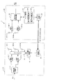
まず、第1実施形態について、図1〜図6を参照して説明する。図1は、開示の無線通信システムの一例である第1実施形態の無線通信システム1の構成を示すブロック図である。図1に示す無線通信システム1はMIMO通信を行うことが可能であり、少なくとも1台の送信側の無線通信装置(送信機)としての基地局10と、少なくとも1台の受信側の無線通信装置(受信機)としての移動局20とを備える。
Embodiments of a disclosed wireless communication method, wireless communication system, and wireless communication apparatus will be described with reference to the accompanying drawings.
(First embodiment)
First, a first embodiment will be described with reference to FIGS. FIG. 1 is a block diagram illustrating a configuration of a
基地局10は、空間多重変調部11と、Lt個(Ltは2以上の整数)の送信RF(Radio Frequency)部12−1〜12−Lt(以下、区別しない場合は送信RF部12と表記する)と、アンテナスイッチ13と、Nt個(Ntは2以上の整数でNt>Lt)の送信アンテナ14−1〜14−Nt(以下、区別しない場合は送信アンテナ14と表記する)と、アンテナ選択制御部15とを備える。送信RF部12がLt個であることは、基地局10で一度に処理可能な送信データストリーム数がLtであることを意味する。基地局10では、Nt個のアンテナからLt個のアンテナを選択して、このLt個のアンテナを使用して送信を行う。
The
また、移動局20は、Nr個(Nrは2以上の整数)の受信アンテナ21−1〜21−Nr(以下、区別しない場合は受信アンテナ21と表記する)と、Lr(Lrは2以上の整数でLr≦Nr)個の受信RF部22−1〜22−Lr(以下、区別しない場合は受信RF部22と表記する)と、MIMO受信信号処理部23と、アンテナ選択部24とを備える。受信RF部22がLr個であることは、移動局20で一度に処理可能な受信データストリーム数がLrであることを意味する。なお、第1実施形態では、受信アンテナ21の個数NrはLrと同じとし、全ての受信アンテナ21を使用して受信を行うものとする。また、以下、受信データストリーム数Lrと送信データストリーム数Ltとは同じLとする。
Further, the
さらに、基地局10はアップリンク受信部32を備え、移動局20はアップリンク送信部31を備えている。そして、基地局10と移動局20との間には、移動局20のアップリンク送信部31から基地局10のアップリンク受信部32へのアップリンクのチャンネルの1つであるフィードバックチャンネル30が設けられている。後述のアンテナインデックス等の情報の転送は、フィードバックチャンネル30を用いて行われる。
Further, the
基地局10において、空間多重変調部11は、送信データを入力し、送信データに所定の誤り訂正符号化を行って得られた符号化系列を所定の変調方式でマッピングして変調し、L個の送信データストリームを出力する。所定の誤り訂正符号化としては、例えばターボ符号化等が用いられる。また、所定の変調方式としては、例えばQPSK(Quadrature Phase Shift Keying)や16QAM(Quadrature Amplitude Modulation)等が用いられる。なお、空間多重変調部11は、データチャンネルの信号以外に、チャンネル推定(チャンネル行列の算出)に使用する既知の信号(パイロット信号あるいはプリアンブル信号)や、制御情報を伝送する制御チャンネルの信号等の多重処理も行う。
In the
送信RF部12は、それぞれ、L個の送信データストリームに関してDA(Digital to Analog)変換や無線周波数(RF)への周波数変換(アップコンバート)等を含む所要の無線送信処理を行い、L個の送信RF信号を出力する。
Each of the
アンテナスイッチ13は、アンテナ選択制御部15による制御に応じて、送信に使用するL個の送信アンテナ14を選択して送信RF部12との接続を行う。
The
送信アンテナ14は、それぞれ、アンテナスイッチ13を介して接続された送信RF部12からの送信RF信号を移動局20に向けて空間へ放射する。
Each of the
アンテナ選択制御部15は、移動局20から送信されたアンテナインデックスに従ってアンテナスイッチ13を制御して送信RF部12と送信アンテナ14との接続を制御する。
The antenna
一方、移動局20において、受信アンテナ21は、それぞれ、基地局10の送信アンテナ14から送信されたRF信号を受信する。
On the other hand, in the
また、受信RF部22は、それぞれ、受信アンテナ21での受信RF信号について、ベースバンド周波数への周波数変換(ダウンコンバート)やAD(Analog to Digital)変換等を含む所要の無線受信処理を施す。
In addition, the
MIMO受信信号処理部23は、受信RF部22で処理された受信信号(デジタルベースバンド信号)、すなわち、空間多重された受信信号を、送信データストリーム毎に分離して、復調、復号を行い、受信データを出力する。第1実施形態において、分離処理は、例えば、チャンネル行列の逆行列を用いて、ZF(Zero Forcing)線形デコードやMMSE(Minimum Mean Square Error:最小二乗誤差法)デコード等の線形デコードにより行われる。なお、信号を分離する手法は、これに限られず、他の一般の手法を用いてもよい。
The MIMO reception
チャンネル行列は、送信アンテナ14と受信アンテナ21との間のチャンネルの状態を表す行列であり、例えば、受信したパイロット信号(あるいは、プリアンブル信号。以下、同じ)と既知のパイロット信号(パイロットレプリカ)との相関演算により算出される。なお、チャンネル行列Hは、Nt個の送信アンテナ14とNr個の受信アンテナ21との間のチャンネルの状態を表すNr×Ntの行列を示す。また、チャンネル行列Hpは、送信アンテナ14のサブセットpに対応する、選択されたL個の送信アンテナ14と、Nr個の受信アンテナ21との間のチャンネルの状態を表すNr×Lの行列を示す。なお、サブセットpは、Nt個の送信アンテナ14からL個の送信アンテナ14を選択する1つの組み合わせであり、p∈P(P:送信アンテナ12の全ての取り得るサブセットの集合)である。
The channel matrix is a matrix that represents the state of the channel between the
詳細には、MIMO受信信号処理部23は、受信RF部22から受信アンテナ21−1〜21−Nrに対応する受信信号yi(i=1,2,…,Nr)をそれぞれ入力する。このとき、受信信号yと送信信号sとの関係は、チャンネル行列を用いて次式(1)で表される。
Specifically, the MIMO reception

MIMO受信信号処理部23は、次式(2)に示すように、受信信号yにL×Nrサイズのフィルタ行列Gを適用して、送信信号sの推定値を取得する。そして、MIMO受信信号処理部23は、この分離された信号を復調、復号して受信データを出力する。
As shown in the following equation (2), the MIMO reception
このとき、ZF線形デコードでは、式(3)でδ=0としたフィルタ行列Gが用いられる。また、MMSEデコードでは、式(3)でδ=1としたフィルタ行列Gが用いられる。 At this time, in the ZF linear decoding, a filter matrix G in which δ = 0 in Equation (3) is used. In the MMSE decoding, a filter matrix G in which δ = 1 is used in Expression (3) is used.
アンテナ選択部24は、チャンネル行列の逆行列に関する値を用いて、所定のアンテナ選択基準に基づき、通信に使用するL個の送信アンテナ14を選択する。アンテナ選択基準としては、通信性能を向上させる基準、例えば、SINR(Signal to Interference Noise Ratio)最小値を最大にすることに相当する基準、システム容量を最大にすることに相当する基準、又はMSE(Mean Square Error)を最小にすることに相当する基準等が用いられる。
The
詳細には、例えば、チャンネル行列Hpを用いて、j番目のデータストリームの線形デコードに対するSINRは、次式(4)で示される。 Specifically, for example, using the channel matrix Hp, SINR for linear decoding of the j-th data stream is expressed by the following equation (4).
このとき、SINRの最小値を最大にする基準は、次式(5)で示される。 At this time, the standard for maximizing the minimum value of SINR is expressed by the following equation (5).
そして、MSEを最小にする基準は、式(10)で示される。 The criterion for minimizing MSE is given by equation (10).
上記の式(4)〜(10)に示すように、アンテナ選択基準を満たす送信アンテナ14のサブセットpは、アンテナ行列Hpの逆行列に関する値を算出することにより得ることができる。
As shown in the above equations (4) to (10), the subset p of the
具体的には、第1実施形態では、MSEを最小にすることに相当する、逆行列の対角の和を最小にするアンテナ選択基準(a)が用いられる。または、第1実施形態では、追加したアンテナのSINRを最大にする基準に相当する、逆行列の対角の最後の要素値を最小にするアンテナ選択基準(b)が用いられる。なお、他に、アンテナ選択基準として、逆行列の対角の積が最小となる基準、逆行列の対角の各要素値を反転した値の総和が最大となる基準、又は逆行列の対角の要素値の最大値を最小にする基準を用いてもよい。逆行列に関する値がこれらのアンテナ選択基準を満たすように、通信に使用する送信アンテナ14を選択することで、システム容量の増大やBERの低減を図り通信性能を向上させることができる。
Specifically, in the first embodiment, the antenna selection criterion (a) that minimizes the sum of diagonals of the inverse matrix, which corresponds to minimizing MSE, is used. Alternatively, in the first embodiment, the antenna selection criterion (b) that minimizes the last element value of the diagonal of the inverse matrix, which corresponds to the criterion that maximizes the SINR of the added antenna, is used. In addition, as other antenna selection criteria, a criterion that minimizes the diagonal product of the inverse matrix, a criterion that maximizes the sum of values obtained by inverting each element value of the inverse matrix, or a diagonal of the inverse matrix A criterion for minimizing the maximum value of the element values may be used. By selecting the
このとき、アンテナ選択部24は、Nt個の送信アンテナ14からL個の送信アンテナ14を選択するサブセットpのうち、第1の逆行列算出部25及び第2の逆行列算出部26により算出した逆行列に関する値がアンテナ選択基準を満たすL個の送信アンテナ14を用いて通信を行う。
At this time, the
第1の逆行列算出部25は、Nt個のアンテナから選択した1番目のアンテナについてのチャンネル行列H1を用いて、チャンネル行列H1の逆行列B1を算出する。すなわち、チャンネル行列H1から直接演算により逆行列B1を算出する。
The first inverse
第2の逆行列算出部26は、Nt個の送信アンテナ14のうち既に選択した1〜n番目の送信アンテナ14以外の送信アンテナ14から選択したn+1番目の送信アンテナ14について、1〜n+1番目の送信アンテナ14からなるグループについてのチャンネル行列Hn+1の逆行列Bn+1を、1〜n番目のアンテナからなるグループについてのチャンネル行列Hnの逆行列Bnを用いた演算により算出する。すなわち、逆行列Bnから更新演算により逆行列Bn+1を算出する。
The second inverse
そして、アンテナ選択部24は、1番目の送信アンテナ14として、電力値が最大となる送信アンテナ14を選択して第1の逆行列算出部25により逆行列B1を算出する。また、アンテナ選択部24は、Nt個の送信アンテナのうち既に選択した1〜n番目の送信アンテナ以外の送信アンテナ14から、n+1番目の送信アンテナの候補として送信アンテナ14を1つずつ選択する。そして、アンテナ選択部24は、選択した各候補について第2の逆行列算出処理26により1〜n+1番目の送信アンテナ14からなるグループについてのチャンネル行列の逆行列をそれぞれ算出し、算出した逆行列に関する値が上述のアンテナ選択基準を満たす候補をn+1番目の送信アンテナとして選択する。そして、アンテナ選択部24は、このように送信アンテナを選択する処理を繰り返すことにより、通信に使用するL個のアンテナを選択する。
Then, the
さらに、移動局20のアップリンク送信部31は、選択したL個の送信アンテナ14のアンテナインデックスを、フィードバックチャンネル30を介して基地局10に送信する。
Further, the
なお、MIMO受信信号処理部23による分離処理において、MMSEデコード又はZF線形デコードで用いる式(3)の逆行列Hpとして、アンテナ選択部24におけるアンテナ選択処理で算出した逆行列Hpを用いてもよい。または、MIMO受信信号処理部23による分離処理において、MMSEデコード又はZF線形デコードで用いる式(3)の逆行列Hpを算出する際に、第1及び第2の逆行列算出部25,26を用いて算出してもよい。
In the separation process by the MIMO reception
以下、第1実施形態のMIMO通信1システムの動作、特に、アンテナ選択処理に着目した動作について、図2〜図3を参照して説明する。
Hereinafter, the operation of the
図2のフローチャートに示すように、基地局10及び移動局20は、事前に、自己の送信・受信アンテナ数やデータストリームの処理能力などに関する情報を互いに送受することにより、通信相手のアンテナ数や処理能力を把握する(ステップS11,S21)。
As shown in the flowchart of FIG. 2, the
次に、基地局10は、パイロット信号を移動局20に向けて送信し(ステップS12)、移動局20は、MIMO受信信号処理部23にて、受信したパイロット信号とパイロットレプリカとの相関演算によりチャンネル行列Hを推定する(ステップS22)。
Next, the
次に、移動局20は、アンテナ選択部24にて、逆行列に関する値が所定のアンテナ選択基準を満たすL個の送信アンテナ14のサブセットpを選択する。
Next, the
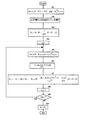
詳細には、アンテナ選択部24は、図3に示すフローチャートのようにL個の送信アンテナ14のサブセットpを決定する。
Specifically, the
まず、アンテナ選択部24は、全ての送信アンテナΩの各送信アンテナjに対し、(j∈Ω={1,2,…,Nt})、次式(11)を用いて電力値g(j)を算出する(S31)。
First, the
次に、アンテナ選択部24は、電力値g(j)が最大となる送信アンテナ14−Jをサブセットpの1番目の送信アンテナ14として選択する(S32)。電力値が最大の送信アンテナ14は、通信性能を向上させる送信アンテナ14のサブセットpに含まれることが想定される。
Next, the
次に、アンテナ選択部24は、第1の逆行列算出部25にて、1番目に選択した送信アンテナ14についてのチャンネル行列H1、チャンネル行列H1の逆行列B1、残された送信アンテナ14の集合Ωを設定する。すなわち、1番目の送信アンテナ14についてのチャンネル行列H1=hJを用いて、チャンネル行列H1の逆行列B1=1/g(J)を直接演算して算出する。そして、残された送信アンテナ14の集合Ω=Ω−{J}を設定する(S33)。
Next, the
次に、アンテナ選択部24は、選択したアンテナ数のカウント値nに1を設定する(S34)。
Next, the
次に、アンテナ選択部24は、残された送信アンテナ14の集合Ωから、n+1番目の送信アンテナ14の候補として送信アンテナjを1つずつ選択する。そして、アンテナ選択部24は、第2の逆行列算出部25にて、選択した各候補jについて、1〜n+1番目のアンテナからなるグループについてのチャンネル行列Hn+1の逆行列Bn+1を、1〜n番目の送信アンテナ14からなるグループについてのチャンネル行列Hnの逆行列Bnを用いてそれぞれ算出する(S35)。
Next, the
具体的には、逆行列Bn+1は、逆行列についての関係式を用いて、次式(12)〜(16)により算出される。 Specifically, the inverse matrix Bn + 1 is calculated by the following expressions (12) to (16) using a relational expression for the inverse matrix.
次に、アンテナ選択部24は、第2の逆行列算出部26にて、S35で算出した逆行列Bn+1に関する値が上述のアンテナ選択基準(a)又は(b)を満たす候補Jをn+1番目の送信アンテナとして選択する(S36)。具体的には、アンテナ選択基準(a)を用いる場合、次式(17)を満たす候補Jを選択する。
Next, the
次に、アンテナ選択部24は、選択したアンテナ数のカウント値nにn+1を設定する(S38)。次に、アンテナ選択部24は、選択したアンテナ数nがL−1以下であるか否かを判断する(S39)。S39の判断結果がYES(n≦L−1)の場合、S35に戻り、アンテナ選択部24は、S35〜S38の処理を繰り返す。
Next, the
S39の判断結果がNO(n>L−1)の場合、S40に進む。これにより、Nt個の送信アンテナ14からL個の送信アンテナ14を選択するサブセットpと、サブセットpについてのチャンネル行列Hpと、逆行列Bpとが取得され(S40)、アンテナ選択処理が終了される。
If the determination result in S39 is NO (n> L-1), the process proceeds to S40. As a result, the subset p for selecting the
図2に戻り、移動局20は、選択されたL個の送信アンテナ14のインデックスを、アップリンク送信部31からフィードバックチャンネル30を介して送信する(S24)。
Returning to FIG. 2, the
次に、基地局10は、送信アンテナ14のインデックスをアップリンク受信部32で受信する(S13)。次に、基地局10は、アンテナ選択制御部15にて、アンテナインデックスに従ってアンテナスイッチ13を制御して送信RF部12と送信アンテナ14との接続を行う(S14)。そして、基地局10は、接続した送信アンテナ14を介してデータを送信し(S15)、移動局20は、送信されたデータを受信アンテナ21で受信し、受信RF部22で変換し、MIMO受信信号処理部23で処理して、受信データを出力する。
Next, the
上述のアンテナ選択処理について、図4の例を用いて具体的に説明する。図4の例では、アンテナ選択部24は、Nt=5個の送信アンテナ14からL=3個の送信アンテナ14を選択する。まず、j∈Ω={1,2,3,4,5}について電力値g(j)が算出され(S31)、電力値g(j)が最大となる送信アンテナ14−1が1番目の送信アンテナ14として選択される(S32)。次に、チャンネル行列H1=h1、逆行列B1=1/g(1)、残された送信アンテナ14の集合Ω={2,3,4,5}が設定される(S33)。そして、選択したアンテナ数のカウント値nに1が設定される(S34)。
The above-described antenna selection process will be specifically described with reference to the example of FIG. In the example of FIG. 4, the
次に、チャンネル行列H1、逆行列B1を用いて、送信アンテナのグループ{1,2}{1,3}{1,4}{1,5}についての逆行列B2(2)、B2(3)、B2(4)、B2(5)がそれぞれ算出され(S35)、アンテナ選択基準を満たす送信アンテナ14−3が2番目の送信アンテナ14として選択される(S36)。次に、1〜2番目の送信アンテナ14についてのチャンネル行列H2=H1+{h3}、逆行列B2=B2(3)、残された送信アンテナ14の集合Ω={2,4,5}が更新される(S37)。そして、選択したアンテナ数のカウント値nに2が設定される(S38)。
Next, using the channel matrix H1 and the inverse matrix B1, inverse matrices B2 (2) and B2 (3) for the transmit antenna group {1,2} {1,3} {1,4} {1,5} are used. ), B2 (4) and B2 (5) are calculated (S35), and the transmission antenna 14-3 satisfying the antenna selection criteria is selected as the second transmission antenna 14 (S36). Next, the channel matrix H2 = H1 + {h3} and the inverse matrix B2 = B2 (3) for the first and
次に、S39の判定結果がYES(2≦3−1)となるのでS35に戻る。そして、チャンネル行列H2、逆行列B2を用いて、送信アンテナ14のグループ{1,3,2}{1,3,4}{1,3,5}についての逆行列B3(2)、B3(4)、B3(5)がそれぞれ算出され、アンテナ選択基準を満たす送信アンテナ14−5が3番目の送信アンテナ14として選択される(S36)。次に、1〜3番目の送信アンテナ14についてのチャンネル行列H3=H2+{h5}、逆行列B3=B3(5)、残された送信アンテナ14の集合Ω={2,4}が更新される(S37)。そして、選択したアンテナ数のカウント値nに3が設定される(S38)。
Next, since the determination result in S39 is YES (2 ≦ 3-1), the process returns to S35. Then, using the
次に、S39の判定結果がNO(3>3−1)となるので、S40に進む。これにより、5個の送信アンテナ14から3個の送信アンテナ14を選択するサブセットp={1,3,5}と、サブセットpについてのチャンネル行列Hpと、逆行列Bpとが取得され、アンテナ選択処理が終了される。
Next, since the determination result of S39 is NO (3> 3-1), the process proceeds to S40. As a result, the subset p = {1, 3, 5} for selecting the three
このように、第1実施形態のアンテナ選択処理によれば、1番目の送信アンテナ14を選択するときのみ直接演算で逆行列を算出し、2番目以降の送信アンテナ14を選択するときには、直接演算より簡易な更新演算で逆行列を算出するので処理時間が低減される。さらに、アンテナ選択基準を満たす送信アンテナ14を順次選択していくことで計算の複雑度が小さくなり処理時間が低減される。そして、このように選択された送信アンテナ14でデータを送信することで、システムの通信性能は、BERとシステム容量の観点から改善される。
Thus, according to the antenna selection processing of the first embodiment, the inverse matrix is calculated by direct calculation only when the
上記の無線通信システム1における通信性能のシミュレーション結果を図6及び図7に示す。以下のシミュレーションでは、送信アンテナ14の個数Nt=9,送信データストリーム数(送信アンテナの使用数)Lt=L=3、受信アンテナ数Nr=L=3として計算した。
The simulation results of the communication performance in the
図5は、無線通信システム1の容量のシミュレーション結果を示すグラフであり、横軸はSNR[dB]を示し、縦軸は容量[bps/Hz]を示す。図5中、“○”で示されているデータは、第1実施形態でMMSEに基づいたアンテナ選択基準(a)基づいて選択した3個の送信アンテナ14を用いた場合を示す。また、図5中、“△”で示されているデータは、第1実施形態でSINRに基づいたアンテナ選択基準(b)に基づいて選択した3個の送信アンテナ14を用いた場合を示す。なお、図5中、“*”で示されているデータは、比較例として、最適値探索計算を行って容量が最大とする3個の送信アンテナ14を選択した例を示す。また、図5中、“□”で示されているデータは、送信アンテナ14を選択せず、予め定められた所定の3個の送信アンテナ14を用いた例を示す。さらに、図5中、「相関なし」として示された上方の4データは、アンテナ間に相関がない場合を示し、「相関あり」として示された下方の4データは、アンテナ間に相関がある場合を示す。
FIG. 5 is a graph showing a simulation result of the capacity of the
図5に示すように、第1実施形態のアンテナ選択基準(a)(b)を用いた場合と最適値探索計算を行った場合とでは、同レベルの容量を示し、送信アンテナ14を選択しない場合に比較して容量が増大している。この傾向は、相関がある場合も相関がない場合も同様である。よって、第1実施形態によれば、最適値探索計算を行って最適な3個の送信アンテナ14を選んだ場合と同様、容量の増大を図り通信性能を向上させることができる。
As shown in FIG. 5, when the antenna selection criteria (a) and (b) of the first embodiment are used and when the optimum value search calculation is performed, the same level of capacity is shown and the
次に、図6は、無線通信システム1のBERのシミュレーション結果を示すグラフであり、横軸はSNR[dB]を示し、縦軸はBERを示す。図6中、“+”で示されているデータは、第1実施形態でMMSEに基づいたアンテナ選択基準(a)に基づいて選択した3個の送信アンテナ14を用いた場合を示す。また、図6中、“□”で示されているデータは、第1実施形態でSINRに基づいたアンテナ選択基準(b)に基づいて選択した3個の送信アンテナ14を用いた場合を示す。なお、図6中、“△”で示されているデータは、比較例として、最適値探索計算を行って容量が最大となる3個の送信アンテナ14を選択して用いた場合を示す。また、図6中、“×”で示されているデータは、比較例として、最適値探索計算を行ってMSEが最小となる3個の送信アンテナ14を選択して用いた場合を示す。また、図6中、“○”で示されているデータは、比較例として、最適値探索計算を行ってSINRの最小値が最大となる3個の送信アンテナ14を選択して用いた場合を示す。また、図6中、“*”で示されているデータは、送信アンテナ14を選択せず、予め定められた所定の3個の送信アンテナ14を用いた例を示す。さらに、図6中、「相関あり」として示された上方の6データは、アンテナ間に相関がある場合を示し、「相関なし」として示された下方の6データは、アンテナ間に相関がない場合を示す。
Next, FIG. 6 is a graph showing a simulation result of the BER of the
図6に示すように、第1実施形態のアンテナ選択基準(a)(b)を用いた場合と最適値探索計算を行った場合とでは、若干の相違はあるものの、ほぼ同レベルのBERが得られ、選択しない場合に比較してBERが低減されている。この傾向は相関がある場合も相関がない場合も同様である。よって、本実施形態によれば、最適値探索計算を行って最適な3個の送信アンテナ14を選んだ場合と同様、BERの低減を図り通信性能を向上させることができる。
As shown in FIG. 6, although there is a slight difference between the case where the antenna selection criteria (a) and (b) of the first embodiment are used and the case where the optimum value search calculation is performed, the BER at almost the same level is obtained. As a result, the BER is reduced as compared with the case where no selection is made. This tendency is the same when there is a correlation and when there is no correlation. Therefore, according to the present embodiment, the BER can be reduced and the communication performance can be improved as in the case where the optimum three
以上から、第1実施形態によれば、MIMO通信可能な無線通信システム1について、少ない処理時間で適切な送信アンテナ14の組み合わせを選択することができる。
(第2実施形態)
次に、第2実施形態について、図7を参照して説明する。なお、第2実施形態の無線通信システムは、第1実施形態の無線通信システム1と、アンテナ選択部24の処理のみが相違する。以下では、他の構成については説明を省略する。
As described above, according to the first embodiment, it is possible to select an appropriate combination of
(Second Embodiment)
Next, a second embodiment will be described with reference to FIG. Note that the wireless communication system of the second embodiment is different from the
第2実施形態では、アンテナ選択部24は、まず、Nt個の送信アンテナ14からL個の送信アンテナ14を選択する全ての取り得るM=Nt!/(L!(Nt−L)!)個のサブセットPを算出する。そして、アンテナ選択部24は、各サブセットp∈Pについて、第1及び第2の逆行列算出部25,26により逆行列Bpを算出する。このとき、アンテナ選択部24は、2番目以降のサブセットpについてのチャンネル行列Hpの逆行列Bpを、算出済みのサブセットq(q=1,2,...,p−1)についてのチャンネル行列Hqの逆行列Bqに関する算出結果を用いて算出する。
In the second embodiment, the
具体的には、アンテナ選択部24は、算出対象のサブセットpと、算出済みのサブセットqとを比較する。そして、最も多く共通するサブセットqについて1〜n番目の送信アンテナからなるグループが共通の場合、第2の逆行列算出部26は、算出対象のサブセットpの1〜n+1番目のアンテナからなるグループについてのチャンネル行列Hp,n+1の逆行列Bp,n+1を、算出済みのサブセットの1〜n番目のアンテナからなるグループについてのチャンネル行列Hq,nの逆行列Bq,nを用いて算出する。そして、アンテナ選択部24は、算出したM個の逆行列Bpに基づいて、算出した逆行列Bpに関する値がアンテナ選択基準を満たすL個の送信アンテナ14のサブセットpを選択する。
Specifically, the
第2実施形態では、アンテナ選択基準として、行列の対角の和を最小にするアンテナ選択基準、逆行列の対角の積が最小となる基準、逆行列の対角の各要素値を反転した値の総和が最大となる基準、又は逆行列の対角の要素値の最大値を最小にする基準が用いられる。逆行列に関する値がこれらのアンテナ選択基準を満たすように、通信に使用する送信アンテナ14を選択することで、システム容量の増大やBERの低減を図り通信性能を向上させることができる。
In the second embodiment, as the antenna selection criterion, the antenna selection criterion that minimizes the sum of the diagonals of the matrix, the criterion that minimizes the product of the diagonals of the inverse matrix, and each element value of the diagonals of the inverse matrix are inverted. A criterion that maximizes the sum of the values or a criterion that minimizes the maximum value of the diagonal elements of the inverse matrix is used. By selecting the
上述のアンテナ選択処理について、図7の例を用いて具体的に説明する。図7の例では、アンテナ選択部24は、Nt=5個の送信アンテナ14からL=3個の送信アンテナ14を選択する。まず、5個の送信アンテナ14から3個の送信アンテナ14を選択する全ての取り得るM=10個のサブセットPが算出される。そして、各サブセット1〜10について、第1及び第2の逆行列算出部25,26により逆行列B1〜B10が算出される。1番目の送信アンテナ14についてのみ直接演算で逆行列を算出し、2番目以降の送信アンテナ14のグループについては、直接演算より簡易な更新演算で逆行列を算出するので処理時間が低減される。
The above-described antenna selection process will be specifically described with reference to the example of FIG. In the example of FIG. 7, the
このとき、図7において、各サブセット1〜10は順に算出されるものとする。そして、図7中、破線で囲んだ送信アンテナ14のグループについての逆行列は、他のサブセットについて算出した逆行列をそのまま用いる。例えば、2番目のサブセット{1,2,4}、3番目のサブセット{1,2,5}については、1番目のサブセットの{1,2}について算出した逆行列を用いて、逆行列が算出される。また、4番目のサブセット{1,3,4}、6番目のサブセット{1,4,5}については、1番目のサブセットの{1}について算出した逆行列を用いて、逆行列が算出される。また、5番目のサブセット{1,3,5}については、4番目のサブセットの{1,3}について算出した逆行列を用いて、逆行列が算出される。また、8番目のサブセット{2,3,4}については、7番目のサブセットの{2,3}について算出した逆行列を用いて、逆行列が算出される。また、9番目のサブセット{2,4,5}については、7番目のサブセットの{2}について算出した逆行列を用いて、逆行列が算出される。これにより、演算を省略して処理時間を低減することができる。
At this time, in FIG. 7, each
以上から、第2実施形態によれば、MIMO通信可能な無線通信システム1について、少ない処理時間で適切な送信アンテナ14の組み合わせを選択することができる。
(第3実施形態)
次に、第3実施形態について、図8を参照して説明する。なお、第3実施形態の無線通信システムは、第1実施形態の無線通信システム1と、アンテナ選択部24の処理のみが相違する。以下では、他の構成については説明を省略する。
As described above, according to the second embodiment, it is possible to select an appropriate combination of
(Third embodiment)
Next, a third embodiment will be described with reference to FIG. The wireless communication system of the third embodiment is different from the
第3実施形態では、アンテナ選択部24は、Nt個の送信アンテナのうち既に選択した1〜n番目の送信アンテナ以外の送信アンテナ14から、n+1番目の送信アンテナの候補として送信アンテナ14を1つずつ選択する。そして、アンテナ選択部24は、選択した各候補について、第2の逆行列算出処理26により、1〜n+1番目の送信アンテナ14からなるグループについてのチャンネル行列の逆行列に関する値(例えば、後述のf(j))を算出する。アンテナ選択部24は、算出した逆行列に関する値が上述のアンテナ選択基準を満たす候補をn+1番目の送信アンテナとして選択する。そして、アンテナ選択部24は、このように送信アンテナを選択する処理を繰り返すことにより、通信に使用するL個のアンテナを選択する。
In the third embodiment, the
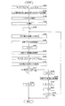
詳細には、アンテナ選択部24は、図8に示すフローチャートのように、L個の送信アンテナ14のサブセットpを決定する。なお、図8のS81〜S84,S88〜S90の処理は、第1実施形態の図3のS31〜S34,S38〜S40の処理と同様であるので、下記では説明を省略する。
Specifically, the
図8のS85で、アンテナ選択部24は、残された送信アンテナ14の集合Ωから、n+1番目の送信アンテナ14の候補として送信アンテナjを1つずつ選択する。そして、アンテナ選択部24は、第2の逆行列算出部25にて、選択した各候補jについて、1〜n+1番目のアンテナからなるグループについてのチャンネル行列Hn+1の逆行列Bn+1に関する値f(j)を、1〜n番目の送信アンテナ14からなるグループについてのチャンネル行列Hnの逆行列Bnを用いてそれぞれ算出する(S85)。具体的には、値f(j)は、逆行列についての関係式を用いて、次式(19)〜(21)により算出される。
In S85 of FIG. 8, the
次に、アンテナ選択部24は、第2の逆行列算出部26にて、S85で算出した逆行列に関する値f(j)が次式(22)を満たす候補Jをn+1番目の送信アンテナとして選択する(S86)。
Next, the
次に、アンテナ選択部24は、1〜n+1番目の送信アンテナ14についてのチャンネル行列Hn+1、チャンネル行列Hn+1の逆行列Bn+1、残された送信アンテナの集合Ωを更新する。すなわち、チャンネル行列Hn+1=Hn+{hJ}、逆行列Bn+1=Bn+1(J)、残された送信アンテナ14の集合Ω=Ω−{J}を設定する(S87)。第3実施形態では、S85では逆行列Bn+1そのものでなく逆行列に関する値f(j)を算出し、S86で候補Jが選択されてから逆行列Bn+1を算出することで、演算を省略して処理時間を低減することができる。
Next, the
そして、第1実施形態と同様、S88〜S90の処理が実行されることにより、Nt個の送信アンテナ14からL個の送信アンテナ14を選択するサブセットpと、サブセットpについてのチャンネル行列Hpと、逆行列Bpとが取得され、アンテナ選択処理が終了される。
Then, as in the first embodiment, by executing the processing of S88 to S90, the subset p for selecting the
以上から、第3実施形態によれば、MIMO通信可能な無線通信システム1について、少ない処理時間で適切な送信アンテナ14の組み合わせを選択することができる。
(第4実施形態)
次に、第4実施形態について、図9〜図10を参照して説明する。なお、第4実施形態の無線通信システムは、第1実施形態の無線通信システム1と、アンテナ選択部24の処理のみが相違する。以下では、他の構成については説明を省略する。
From the above, according to the third embodiment, it is possible to select an appropriate combination of
(Fourth embodiment)
Next, a fourth embodiment will be described with reference to FIGS. Note that the wireless communication system of the fourth embodiment is different from the
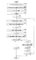
図9は、第4実施形態におけるアンテナ選択処理を示すフローチャートである。第4実施形態では、アンテナ選択部24は、第2実施形態と同様、まず、Nt個の送信アンテナ14からL個の送信アンテナ14を選択する全ての取り得るM=Nt!/(L!(Nt−L)!)個のサブセットPを算出する(S91)。そして、アンテナ選択部24は、各サブセットp∈Pについて、第1及び第2の逆行列算出部25,26により逆行列Bpを算出する。このとき、アンテナ選択部24は、1番目のサブセットについてのチャンネル行列Hpの逆行列Bpを、第2実施形態と同様に算出する(S92)。1番目の送信アンテナ14についてのみ直接演算で逆行列を算出し、2番目以降の送信アンテナ14のグループについては、直接演算より簡易な更新演算で逆行列を算出するので処理時間が低減される。また、アンテナ選択部24は、2番目以降のサブセットpについてのチャンネル行列Hpの逆行列Bpを、算出済みのサブセットq(q=1,2,...,p−1)についてのチャンネル行列Hqの逆行列Bqに関する算出結果を用いて算出する。
FIG. 9 is a flowchart showing antenna selection processing in the fourth embodiment. In the fourth embodiment, the
具体的には、アンテナ選択部24は、算出対象のサブセットpと、算出済みのサブセットqとを比較する(S93)。そして、比較の結果に応じて(S94)、例えば、最も多く共通するサブセットqについて1〜n番目の送信アンテナからなるグループが共通の場合でnが所定値以上のときは、第2の逆行列算出部26は、第2実施形態と同様、算出対象のサブセットpの1〜n+1番目のアンテナからなるグループについてのチャンネル行列Hp,n+1の逆行列Bp,n+1を、算出済みのサブセットの1〜n番目の送信アンテナからなるグループについてのチャンネル行列Hq,nの逆行列Bq,nを用いて算出する(S95)。
Specifically, the
また、比較の結果に応じて(S94)、例えば、最も多く共通するサブセットqについて1〜n番目の送信アンテナからなるグループが共通の場合でnが所定値未満のときは、第2の逆行列算出部26は、相違する送信アンテナ数が最も少ないサブセットqのチャンネル行列Hqの逆行列Bqに対して、相違する送信アンテナに対応する要素を入れ替える入替処理を実行して、算出対象のサブセットpについての逆行列Bpを算出する(S96)。
Further, according to the comparison result (S94), for example, when the group consisting of the 1st to nth transmission antennas is common for the most common subset q, and when n is less than a predetermined value, the second inverse matrix The
この入替処理では、サブセットpとサブセットqで、j番目の送信アンテナが相違する場合、まず、逆行列Bqから、サブセットqのj番目の送信アンテナに対応する要素を削除し、次いで、サブセットpのj番目の送信アンテナに対応する要素を追加して、逆行列Bpを算出する。 In this replacement process, when the j-th transmission antenna is different between the subset p and the subset q, first, the element corresponding to the j-th transmission antenna of the subset q is deleted from the inverse matrix Bq, and then the subset p An inverse matrix Bp is calculated by adding an element corresponding to the j-th transmission antenna.
1〜n+1番目のアンテナからなるグループについてのチャンネル行列Hn+1の逆行列Bn+1から、j番目の送信アンテナに対応する要素を削除するには、まず、第2の逆行列算出部26は、次式(23)のように、逆行列Bn+1のj行とj列と、逆行列Bn+1の最後の行と列とを交換した行列Bn+1'を算出する。
In order to delete the element corresponding to the jth transmission antenna from the inverse matrix Bn + 1 of the channel matrix Hn + 1 for the group of 1st to (n + 1) th antennas, first, the second inverse
式(23)の行列Bn+1'を用いて、上述の式(12)〜(16)と同様、逆行列についての関係式から、j番目の送信アンテナに対応する要素を削除した逆行列Bn'が次式(24)のように算出される。 Using the matrix Bn + 1 ′ of Expression (23), the inverse matrix Bn in which the element corresponding to the j-th transmission antenna is deleted from the relational expression regarding the inverse matrix, as in Expressions (12) to (16) above. 'Is calculated as in the following equation (24).
そして、アンテナ選択部24は、M個の逆行列Bpを算出すると(S97)、算出したM個の逆行列Bpに基づいて、第2実施形態と同様に、算出した逆行列Bpに関する値がアンテナ選択基準を満たすL個の送信アンテナ14のサブセットpを選択する(S98)。
Then, when the
上述のアンテナ選択処理について、図10の例を用いて具体的に説明する。図10の例では、アンテナ選択部24は、Nt=8個の送信アンテナ14からL=7個の送信アンテナ14を選択する。まず、8個の送信アンテナ14から7個の送信アンテナ14を選択する全ての取り得るM=8個のサブセットPが算出される。そして、各サブセット1〜8について、第1及び第2の逆行列算出部25,26により逆行列B1〜B8が算出される。1番目の送信アンテナ14についてのみ直接演算で逆行列を算出し、2番目以降の送信アンテナ14のグループについては、直接演算より簡易な更新演算で逆行列を算出するので処理時間が低減される。
The above-described antenna selection processing will be specifically described using the example of FIG. In the example of FIG. 10, the
このとき、図10において、各サブセット1〜8は順に算出されるものとする。そして、破線で囲んだ送信アンテナ14のグループについての逆行列は、他のサブセットについて算出した逆行列をそのまま用いる。例えば、2番目のサブセットについての逆行列は、1番目のサブセットのグループ{1,2,3,4,5,6}について算出した逆行列を用いて算出される。また、3番目のサブセットについての逆行列は、1番目のサブセットのグループ{1,2,3,4,5}について算出した逆行列を用いて算出される。これにより、演算を省略して処理時間を低減することができる。
At this time, in FIG. 10, each subset 1-8 shall be calculated in order. Then, as the inverse matrix for the group of
さらに、4番目以降のサブセットについての逆行列は、算出済みのサブセットについての逆行列に、相違する送信アンテナ14(図10中、実線で囲んだ送信アンテナ14)に対応する要素を入れ替える入替処理を行って算出する。例えば、4番目のサブセットについての逆行列は、3番目のサブセットについての逆行列について、送信アンテナ{5}を削除して送信アンテナ{6}を追加する処理を行って算出される。これにより、演算を省略して処理時間を低減することができる。
Further, the inverse matrix for the fourth and subsequent subsets is a replacement process for replacing elements corresponding to different transmission antennas 14 (
以上から、第4実施形態によれば、MIMO通信可能な無線通信システム1について、少ない処理時間で適切な送信アンテナ14の組み合わせを選択することができる。
(第5実施形態)
次に、第5実施形態について図9を参照して説明する。なお、第5実施形態の無線通信システムは、第1実施形態の無線通信システム1と、アンテナ選択部24の処理のみが相違する。以下では、他の構成については説明を省略する。また、第5実施形態のアンテナ選択部24の処理は、図9の第4実施形態のアンテナ選択部24の処理と、相違する送信アンテナに対応する要素を入れ替える入替処理(S96)の詳細のみが相違する。
As described above, according to the fourth embodiment, an appropriate combination of
(Fifth embodiment)
Next, a fifth embodiment will be described with reference to FIG. Note that the wireless communication system of the fifth embodiment is different from the
第5実施形態において、アンテナ選択部24は、第4実施形態と同様、まず、Nt個の送信アンテナ14からL個の送信アンテナ14を選択する全ての取り得るM=Nt!/(L!(Nt−L)!)個のサブセットPを算出する。そして、アンテナ選択部24は、各サブセットp∈Pについて、第1及び第2の逆行列算出部25,26により逆行列Bpを算出する。アンテナ選択部24は、2番目以降のサブセットpについてのチャンネル行列Hpの逆行列Bpを、算出済みのサブセットq(q=1,2,...,p−1)についてのチャンネル行列Hqの逆行列Bqに関する算出結果を用いて算出する。
In the fifth embodiment, the
具体的には、アンテナ選択部24は、算出対象のサブセットpと、算出済みのサブセットqとを比較する。そして、比較の結果に応じて、例えば、最も多く共通するサブセットqについて1〜n番目の送信アンテナからなるグループが共通の場合でnが所定値未満のときは、第2の逆行列算出部26は、相違する送信アンテナ数が最も少ないサブセットqのチャンネル行列Hqの逆行列Bqに対して、相違する送信アンテナに対応する要素を入れ替える入替処理を実行して、算出対象のサブセットpについての逆行列Bpを算出する。これにより、演算を省略して処理時間を低減することができる。
Specifically, the
このとき、第5実施形態の入替処理では、サブセットpとサブセットqで、j番目の送信アンテナが相違する場合、逆行列Bqのj番目の送信アンテナに対応する要素自体を変更して逆行列Bpが算出される。すなわち、逆行列Bqのj列を変更することにより逆行列Bpが算出される。 At this time, in the replacement processing of the fifth embodiment, when the j-th transmission antenna is different between the subset p and the subset q, the element corresponding to the j-th transmission antenna of the inverse matrix Bq is changed to change the inverse matrix Bp. Is calculated. That is, the inverse matrix Bp is calculated by changing j columns of the inverse matrix Bq.
ここで、行列Qのj列を列ベクトルhで入れ替えた行列Pは、次式(26)のように行列Dを算出し、行列Dを用いて、行列の数学的な関係式に基づいて次式(27)により算出される。 Here, the matrix P obtained by replacing the j column of the matrix Q with the column vector h calculates the matrix D as in the following equation (26), and uses the matrix D to calculate the following based on the mathematical relational expression of the matrix: Calculated by equation (27).
(第6実施形態)
次に、第6実施形態について、図11〜図12を参照して説明する。図11は、開示の無線通信システムの一例である第6実施形態の無線通信システム40の構成を示すブロック図である。図11に示す無線通信システム40はMIMO通信を行うことが可能であり、少なくとも1台の送信側の無線通信装置(送信機)としての基地局50と、少なくとも1台の受信側の無線通信装置(受信機)としての移動局60とを備える。
(Sixth embodiment)
Next, a sixth embodiment will be described with reference to FIGS. FIG. 11 is a block diagram illustrating a configuration of a
基地局50は、空間多重変調部51と、Lt個(Ltは2以上の整数)の送信RF(Radio Frequency)部52−1〜52−Lt(以下、区別しない場合は送信RF部52と表記する)と、Nt個(Ntは2以上の整数でNt=Lt)の送信アンテナ53−1〜53−Nt(以下、区別しない場合は送信アンテナ53と表記する)とを備える。送信RF部52がLt個であることは、基地局50で一度に処理可能な送信データストリーム数がLtであることを意味する。なお、第6実施形態では、送信アンテナ53の個数NtはLrと同じとし、全ての送信アンテナ53を使用する。
The
また、移動局60は、Nr個(Nrは2以上の整数)の受信アンテナ61−1〜61−Nr(以下、区別しない場合は受信アンテナ61と表記する)と、アンテナスイッチ62と、Lr(Lrは2以上の整数でLr<Nr)個の受信RF部63−1〜63−Lr(以下、区別しない場合は受信RF部63と表記する)と、MIMO受信信号処理部64と、アンテナ選択部65と、アンテナ選択制御部66とを備える。受信RF部63がLr個であることは、移動局60で一度に処理可能な受信データストリーム数がLrであることを意味する。移動局60では、Nr個のアンテナからLr個のアンテナを選択して、このLr個のアンテナを使用して受信を行う。また、以下、受信データストリーム数Lrと送信データストリーム数Ltとは同じLとする。
In addition, the
基地局50において、空間多重変調部51、送信RF部52、送信アンテナ53の詳細は、第1実施形態の基地局10における空間多重変調部11、送信RF部12、送信アンテナ14と同様である。
In the
一方、移動局60において、受信アンテナ61、受信RF部63、MIMO受信信号処理部64の詳細は、第1実施形態の移動局20における受信アンテナ21、受信RF部22、MIMO受信信号処理部23と同様である。
On the other hand, in the
また、移動局60において、アンテナスイッチ62は、アンテナ選択制御部66による制御に応じて、受信に使用するL個の受信アンテナ61を選択して受信RF部63との接続を行う。
In the
アンテナ選択制御部66は、アンテナ選択部65から送信されたアンテナインデックスに従ってアンテナスイッチ62を制御して受信RF部63と受信アンテナ61との接続を制御する。
The antenna
アンテナ選択部65は、チャンネル行列の逆行列に関する値を用いて、所定のアンテナ選択基準に基づき、通信に使用するL個の受信アンテナ61を選択する。アンテナ選択基準としては、通信性能を向上させる基準、例えば、SINR最小値を最大にすることに相当する基準、システム容量を最大にすることに相当する基準、又はMSEを最小にすることに相当する基準等が用いられる。
The
このとき、アンテナ選択部65は、Nr個の送信アンテナ61からL個の受信アンテナ61を選択するサブセットpのうち、第1の逆行列算出部67及び第2の逆行列算出部68により算出した逆行列に関する値がアンテナ選択基準を満たすL個の受信アンテナ61を用いて通信を行う。具体的には、第2実施形態と同様、アンテナ選択基準として、行列の対角の和を最小にするアンテナ選択基準、逆行列の対角の積が最小となる基準、逆行列の対角の各要素値を反転した値の総和が最大となる基準、又は逆行列の対角の要素値の最大値を最小にする基準が用いられる。逆行列に関する値がこれらのアンテナ選択基準を満たすように、通信に使用する受信アンテナ61を選択することで、システム容量の増大やBERの低減を図り通信性能を向上させることができる。
At this time, the
図12は、第6実施形態におけるアンテナ選択処理を示すフローチャートである。第6実施形態では、アンテナ選択部65は、まず、第2実施形態と同様、Nr個の受信アンテナ14からL個の受信アンテナ61を選択する全ての取り得るM=Nr!/(L!(Nr−L)!)個のサブセットPを算出する(S121)。そして、アンテナ選択部65は、各サブセットp∈Pについて、第1及び第2の逆行列算出部67,68により逆行列Bpを算出する。このとき、アンテナ選択部65は、1番目のサブセットについてのチャンネル行列Hpの逆行列Bpを、第2実施形態と同様に算出する(S122)。1番目の受信アンテナ61についてのみ直接演算で逆行列を算出し、2番目以降の受信アンテナ61のグループについては、直接演算より簡易な更新演算で逆行列を算出するので処理時間が低減される。
FIG. 12 is a flowchart showing antenna selection processing in the sixth embodiment. In the sixth embodiment, the
また、アンテナ選択部65は、2番目以降のサブセットpについてのチャンネル行列Hpの逆行列Bpを、算出済みのサブセットq(q=1,2,...,p−1)についてのチャンネル行列Hqの逆行列Bqに関する算出結果を用いて算出する。
Further, the
具体的には、アンテナ選択部65は、算出対象のサブセットpと、算出済みのサブセットqとを比較する(S123)。そして、第2の逆行列算出部68は、相違する受信アンテナ数が最も少ないサブセットqのチャンネル行列Hqの逆行列Bqに対して、相違する受信アンテナに対応する要素を入れ替える入替処理を実行して、算出対象のサブセットpについての逆行列Bpを算出する(S124)。これにより、演算を省略して処理時間を低減することができる。
Specifically, the
この入替処理では、サブセットpとサブセットqで、j番目の受信アンテナが相違する場合、逆行列Bqのj番目の受信アンテナに対応する要素自体を変更して逆行列Bpが算出される。すなわち、逆行列Bqのj行を変更することにより逆行列Bpが算出される。 In this replacement process, when the j-th receiving antenna is different between the subset p and the subset q, the inverse matrix Bp is calculated by changing the element corresponding to the j-th receiving antenna of the inverse matrix Bq. That is, the inverse matrix Bp is calculated by changing j rows of the inverse matrix Bq.
ここで、行列Qのj行を行ベクトルhで入れ替えた行列Pは、次式(28)のように行列Dを算出し、行列Dを用いて、行列の数学的な関係式に基づいて次式(29)により算出される。 Here, the matrix P obtained by replacing the j rows of the matrix Q with the row vector h calculates the matrix D as in the following equation (28), and uses the matrix D to calculate the following based on the mathematical relational expression of the matrix: Calculated by equation (29).
以上から、第6実施形態によれば、MIMO通信可能な無線通信システム40について、少ない処理時間で適切な受信アンテナ61の組み合わせを選択することができる。
As described above, according to the sixth embodiment, an appropriate combination of receiving
なお、他の実施形態として、Nt個の送信アンテナ14からL個の送信アンテナ14を選択する全ての組み合わせ数Mが所定の基準数以上の場合は、第1実施形態と同様にL個の送信アンテナ14を選択し、Mが基準数未満の場合は、第2実施形態と同様にL個の送信アンテナ14を選択するものとしてもよい。この場合、組み合わせ数Mが基準数以上で比較的多い場合、電力が最大となるアンテナを1番目のアンテナとして選択し、2番目以降の送信アンテナ14をアンテナ選択基準を満たすように順次選択していく。また、組み合わせ数Mが基準数未満で比較的少ない場合、N個のアンテナからL個のアンテナを選択する全ての組み合わせについて、第1及び第2の逆行列算出部25,26により逆行列を算出してL個のアンテナを選択する。
As another embodiment, when the number of all combinations M for selecting
また、他の実施形態として、基地局10がアンテナ選択部、第1及び第2の逆行列算出部を備えるものとしてもよい。この場合、例えば、移動局20がチャンネル行列に関する情報を基地局10へ送信し、この情報を用いてアンテナ選択部24、第1及び第2の逆行列算出部25,26はチャンネル行列の逆行列を算出する。
(第7実施形態)
次に、第7実施形態について、図13を参照して説明する。なお、第7実施形態の無線通信システムは、第1実施形態の無線通信システム1と、アンテナ選択部24の処理のみが相違する。以下では、他の構成については説明を省略する。
As another embodiment, the
(Seventh embodiment)
Next, a seventh embodiment will be described with reference to FIG. Note that the radio communication system of the seventh embodiment is different from the
図13は、第7実施形態におけるアンテナ選択処理を示すフローチャートである。第7実施形態では、アンテナ選択部24は、まず、上述の式(11)を用いて、全ての送信アンテナΩの各送信アンテナjに対し(j∈Ω={1,2,…,Nt})、電力値g(j)を算出する(S1301)。
FIG. 13 is a flowchart showing antenna selection processing in the seventh embodiment. In the seventh embodiment, the
次に、アンテナ選択部24は、電力値g(j)が最大となる送信アンテナを含むL個の送信アンテナ14のサブセットωを選択する(S1302)。なお、L個の送信アンテナ14は、例えば、任意に選択してもよいし、電力値g(j)が大きい順に選択してもよい。
Next, the
次に、アンテナ選択部24は、サブセットωについてのチャンネル行列Hと、残された送信アンテナ14の集合Ω=Ω−ωを設定する(S1303)。
Next, the
次に、アンテナ選択部24は、サブセットωについてのチャンネル行列Hの逆行列Bを算出する(S1304)。そして、アンテナ選択部24は、カウント値nに1を設定する(S1305)。
Next, the
次に、アンテナ選択部24は、次式(30)により、サブセットωについての逆行列Bに基づいて、サブセットωのうちのSINRが最小となる送信アンテナIを特定する(S1306)。式(30)は、サブセットωに含まれる送信アンテナiのうち、逆行列Bの対角要素が示すMSEが最大となる送信アンテナIを特定することに相当する。
Next, the
次に、アンテナ選択部24は、送信アンテナIに対応するMSE(I)が、送信アンテナJに対応するMSE(J)=1/f(J)より大きいか否かを判定する(S1312)。
Next, the
MSE(I)≦1/f(J)の場合(S1312がNO)、アンテナ選択部24は、サブセットωに削除した送信アンテナIを戻し、逆行列Bに送信アンテナIに対応する要素を戻し(S1313)、アンテナ選択処理を終了する。
If MSE (I) ≦ 1 / f (J) (NO in S1312), the
MSE(I)>1/f(J)の場合(S1312がYES)、アンテナ選択部24は、サブセットωに送信アンテナJを追加し(S1314)、上述の式(25)を用いて、送信アンテナJに対応する要素を追加する処理を行って逆行列Bを更新する(S1315)。次に、アンテナ選択部24は、残された送信アンテナ14の集合Ω=(Ω−J)+Iを設定し(S1306)、カウント値nにn+1を設定する(S1305)。そして、アンテナ選択部24は、カウント値nがL以下であるか否かを判定する(S1318)。n≦Lの場合(S1318がYES)、アンテナ選択部24はS1306に戻り処理を繰り返し、n≦Lの場合(S1318がYES)、アンテナ選択部24はアンテナ選択処理を終了する。
When MSE (I)> 1 / f (J) (YES in S1312), the
第7実施形態によれば、MIMO通信可能な無線通信システム1について、少ない処理時間で適切な送信アンテナ14の組み合わせを選択することができる。
According to the seventh embodiment, an appropriate combination of
なお、第7実施形態では、S1301〜S1302で、g(j)を算出し、g(j)の最大値を含むL個のアンテナを選択するものとしたが、g(j)を算出せず、任意のL個のアンテナを選択して、S1303〜S1318の処理を行うものとしてもよい。 In the seventh embodiment, g (j) is calculated in S1301 to S1302, and L antennas including the maximum value of g (j) are selected. However, g (j) is not calculated. Alternatively, any L antennas may be selected and the processing of S1303 to S1318 may be performed.
また、第7実施形態では、S1316で、残された送信アンテナ14の集合ΩにIを戻したが、Iを戻さずJを削除するのみで処理を継続してもよい。
(第8実施形態)
次に、第8実施形態について、図14を参照して説明する。なお、第8実施形態の無線通信システムは、第1実施形態の無線通信システム1と、アンテナ選択部24の処理のみが相違する。以下では、他の構成については説明を省略する。
In the seventh embodiment, I is returned to the set Ω of the remaining
(Eighth embodiment)
Next, an eighth embodiment will be described with reference to FIG. Note that the radio communication system of the eighth embodiment is different from the
図14は、第8実施形態におけるアンテナ選択処理を示すフローチャートである。第8実施形態では、アンテナ選択部24は、第7実施形態と同様に、まず、上述の式(11)を用いて、全ての送信アンテナΩの各送信アンテナjに対し(j∈Ω={1,2,…,Nt})、電力値g(j)を算出する(S1401)。
FIG. 14 is a flowchart showing antenna selection processing in the eighth embodiment. In the eighth embodiment, as in the seventh embodiment, the
次に、アンテナ選択部24は、電力値g(j)が最大となる送信アンテナを含むL個の送信アンテナ14のサブセットωを選択する(S1402)。なお、L個の送信アンテナ14は、例えば、任意に選択してもよいし、電力値g(j)が大きい順に選択してもよい。
Next, the
次に、アンテナ選択部24は、サブセットωについてのチャンネル行列Hと、残された送信アンテナ14の集合Ω=Ω−ωを設定する(S1403)。次に、アンテナ選択部24は、サブセットωについてのチャンネル行列Hの逆行列Bを算出する(S1404)。そして、アンテナ選択部24は、カウント値nに1を設定する(S1405)。
Next, the
次に、アンテナ選択部24は、上述の式(30)により、サブセットωについての逆行列Bに基づいて、サブセットωのうちのSINRが最小となる送信アンテナIを特定する(S1406)。次に、アンテナ選択部24は、特定した送信アンテナIに対応する第1実施形態で述べたようなアンテナ選択基準を示す値E(I)を保存する(S1407)。具体的には、例えば、逆行列の対角の和が最小となる基準A、逆行列の対角の積が最小となる基準、逆行列の対角のよう措置の最大値が最小となる基準、又は逆行列の対角の各要素値を反転した値の総和が最大となる基準Dが用いられる。
Next, the
次に、アンテナ選択部24は、サブセットωから送信アンテナIを削除する(S1408)。次に、アンテナ選択部24は、上述の式(24)を用いて、送信アンテナIに対応する要素を削除する処理を行い、逆行列Bを更新する(S1409)。次に、アンテナ選択部24は、残された送信アンテナ14の集合Ωから1つずつ送信アンテナを選択し、選択した送信アンテナを追加したアンテナセットについて、上述の式(12)〜(16)を用いて逆行列B(j)を算出し(S1410)、逆行列B(j)に基づいてアンテナ選択基準に関するE(j)が最良となる送信アンテナJを特定する(S1411)。すなわち、
次に、アンテナ選択部24は、送信アンテナIに対応するE(I)より、送信アンテナJに対応するE(J)が良いか否かを判定する(S1412)。具体的には、例えば、選択基準A,B,Cを用いる場合、E(J)>E(I)のときが(J)がE(I)より良いことを示し、選択基準Dを用いる場合、E(J)<E(I)のときが(J)がE(I)より良いことを示す。
Next, the
Next, the
E(J)がE(I)と同じか悪い場合(S1412がNO)、アンテナ選択部24は、サブセットωに削除した送信アンテナIを戻し、逆行列Bに送信アンテナIに対応する要素を戻し(S1413)、アンテナ選択処理を終了する。
When E (J) is the same as or worse than E (I) (NO in S1412), the
E(J)がE(I)より良い場合(S1412がYES)、アンテナ選択部24は、サブセットωに送信アンテナJを追加し(S1414)、上述の式(25)を用いて、送信アンテナJに対応する要素を追加する処理を行って逆行列Bを更新する(S1415)。次に、アンテナ選択部24は、残された送信アンテナ14の集合Ω=(Ω−J)+Iを設定し(S1406)、カウント値nにn+1を設定する(S1405)。そして、アンテナ選択部24は、カウント値nがL以下であるか否かを判定する(S1418)。n≦Lの場合(S1418がYES)、アンテナ選択部24はS1406に戻り処理を繰り返し、n≦Lの場合(S1418がYES)、アンテナ選択部24はアンテナ選択処理を終了する。
When E (J) is better than E (I) (YES in S1412), the
第8実施形態によれば、MIMO通信可能な無線通信システム1について、少ない処理時間で適切な送信アンテナ14の組み合わせを選択することができる。
According to the eighth embodiment, an appropriate combination of
なお、第8実施形態では、S1401〜S1402で、g(j)を算出し、g(j)の最大値を含むL個のアンテナを選択するものとしたが、g(j)を算出せず、任意のL個のアンテナを選択して、S1403〜S1418の処理を行うものとしてもよい。 In the eighth embodiment, g (j) is calculated in S1401 to S1402 and L antennas including the maximum value of g (j) are selected. However, g (j) is not calculated. Alternatively, any L antennas may be selected and the processing of S1403 to S1418 may be performed.
また、第8実施形態では、S1416で、残された送信アンテナ14の集合ΩにIを戻したが、Iを戻さずJを削除するのみで処理を継続してもよい。
In the eighth embodiment, I is returned to the remaining set Ω of the
また、第1〜第8実施形態では、1つの基地局と1つの移動局とを例に説明したが、これには限られない。例えば、第1〜第5実施形態について、マルチユーザMIMOシステムにおけるアップリンク時のユーザ選択に用いてもよい。また、例えば、第6実施形態について、マルチユーザMIMOシステムにおけるダウンリンク時のユーザ選択に用いてもよい。 In the first to eighth embodiments, one base station and one mobile station have been described as examples. However, the present invention is not limited to this. For example, the first to fifth embodiments may be used for user selection during uplink in a multiuser MIMO system. Further, for example, the sixth embodiment may be used for user selection at the time of downlink in the multi-user MIMO system.
また、第1〜第8実施形態における無線通信システムを、OFDM(Orthogonal Frequency Division Multiplexing)無線通信システムのサブキャリアシステムとして用いてもよい。 Moreover, you may use the radio | wireless communications system in 1st-8th embodiment as a subcarrier system of an OFDM (Orthogonal Frequency Division Multiplexing) radio | wireless communications system.
以上の実施形態に関し、更に以下の付記を開示する。 Regarding the above embodiment, the following additional notes are disclosed.
(付記1)
N個(Nは2以上の整数)のアンテナを有する無線通信装置を用いてMIMO(Multiple Input Multiple Output)通信が可能な無線通信方法において、前記N個のアンテナから選択した1番目のアンテナについてのチャンネル行列を用いて、該チャンネル行列の逆行列を算出する第1の逆行列算出処理を行い、前記N個のアンテナのうち既に選択した1〜n番目(n=1,2,…,L−1、Lはアンテナの所定の使用数で2以上N以下の整数)のアンテナ以外のアンテナから選択したn+1番目のアンテナについて、1〜n+1番目のアンテナからなるグループについてのチャンネル行列の逆行列を、1〜n番目のアンテナからなるグループについてのチャンネル行列の逆行列を用いた演算により算出する第2の逆行列算出処理を行い、前記N個のアンテナから前記L個のアンテナを選択する組み合わせのうち、前記第1及び第2の逆行列算出処理により算出した逆行列に関する値が所定のアンテナ選択基準を満たすL個のアンテナの組み合わせを用いて通信を行う、
無線通信方法。
(Appendix 1)
In a wireless communication method capable of MIMO (Multiple Input Multiple Output) communication using a wireless communication apparatus having N antennas (N is an integer of 2 or more), the first antenna selected from the N antennas A first inverse matrix calculation process for calculating an inverse matrix of the channel matrix is performed using the channel matrix, and the first to nth (n = 1, 2,..., L−) already selected from the N antennas. 1, L is a predetermined number of antennas and is an integer of 2 or more and N or less) For an n + 1-th antenna selected from an antenna other than an antenna, an inverse matrix of a channel matrix for a group consisting of 1 to n + 1-th antennas, Performing a second inverse matrix calculation process for calculating by using an inverse matrix of a channel matrix for a group of 1st to nth antennas, and said N antennas Among the combinations for selecting the L antennas from the above, communication is performed using a combination of L antennas whose values related to the inverse matrices calculated by the first and second inverse matrix calculation processes satisfy a predetermined antenna selection criterion. Do,
Wireless communication method.
(付記2)
前記N個のアンテナのうち既に選択した1〜n番目のアンテナ以外のアンテナから、n+1番目のアンテナの候補としてアンテナを1つずつ選択し、選択した各候補について前記第2の逆行列算出処理により1〜n+1番目のアンテナからなるグループについての逆行列をそれぞれ算出し、算出した該逆行列に関する値が所定の第1のアンテナ選択基準を満たす前記候補をn+1番目のアンテナとして決定する処理を繰り返すことにより得られる、L個のアンテナの組み合わせを用いて通信を行う付記1に記載の無線通信方法。
(Appendix 2)
From the antennas other than the 1st to nth antennas already selected from the N antennas, antennas are selected one by one as candidates for the (n + 1) th antenna, and for each selected candidate, the second inverse matrix calculation process is performed. Repeating the process of calculating an inverse matrix for each of the groups of 1 to n + 1th antennas and determining the candidate satisfying a predetermined first antenna selection criterion as a value of the calculated first matrix as the (n + 1) th antenna. The wireless communication method according to
(付記3)
前記N個のアンテナのうち電力が最大となるアンテナを、前記1番目のアンテナとして選択する付記1又は2に記載の無線通信方法。
(Appendix 3)
The wireless communication method according to
(付記4)
前記N個のアンテナから前記L個のアンテナを選択する複数の組み合わせについて、前記第1及び第2の逆行列算出処理により算出した逆行列に基づいて、算出した該逆行列に関する値が所定の第2のアンテナ選択基準を満たすL個のアンテナの組み合わせを用いて通信を行う付記1に記載の無線通信方法。
(Appendix 4)
For a plurality of combinations for selecting the L antennas from the N antennas, a value related to the inverse matrix calculated based on the inverse matrices calculated by the first and second inverse matrix calculation processes is a predetermined value. The wireless communication method according to
(付記5)
前記N個のアンテナから前記L個のアンテナを選択する各組み合わせについてのチャンネル行列の逆行列を算出する際に、他の組み合わせについて既に算出したチャンネル行列の逆行列を用いる付記4に記載の無線通信方法。
(Appendix 5)
The wireless communication according to
(付記6)
前記N個のアンテナから前記L個のアンテナを選択する一の組み合わせについて、前記第2の逆行列算出処理により1〜n+1番目のアンテナからなるグループについてのチャンネル行列の逆行列を算出する際に、他の組み合わせについて前記第1及び第2の逆行列算出処理により既に算出した1〜n番目のアンテナからなるグループについてのチャンネル行列の逆行列を用いて算出する付記4に記載の無線通信方法。
(Appendix 6)
When calculating the inverse matrix of the channel matrix for the group of 1 to n + 1 antennas by the second inverse matrix calculation process for one combination of selecting the L antennas from the N antennas, The wireless communication method according to
(付記7)
前記N個のアンテナから前記L個のアンテナを選択する一の組み合わせについてのチャンネル行列の逆行列を算出する際に、他の組み合わせについて既に算出したチャンネル行列の逆行列に対して該一の組み合わせと該他の組み合わせとで相違するアンテナに対応する要素を入れ替える入替処理を行って算出する付記5又は6に記載の無線通信方法。
(Appendix 7)
When calculating an inverse matrix of a channel matrix for one combination that selects the L antennas from the N antennas, the one combination with respect to the inverse matrix of the channel matrix that has already been calculated for another combination The wireless communication method according to
(付記8)
前記N個のアンテナから前記L個のアンテナを選択する全ての組み合わせ数Mが所定の基準数以上の場合、前記1番目のアンテナとして電力が最大となるアンテナを選択し、前記N個のアンテナのうち既に選択した1〜n番目のアンテナ以外のアンテナから、n+1番目のアンテナの候補としてアンテナを1つずつ選択し、選択した各候補について前記第2の逆行列算出処理により1〜n+1番目のアンテナからなるグループについての逆行列をそれぞれ算出し、算出した該逆行列に関する値が所定の第1のアンテナ選択基準を満たす前記候補をn+1番目のアンテナとして決定する処理を繰り返すことにより得られる、L個のアンテナの組み合わせを用いて通信を行い、組み合わせ数Mが所定の基準数未満の場合、前記N個のアンテナから前記L個のアンテナを選択する全ての組み合わせについて、前記第1及び第2の逆行列算出処理により算出した逆行列に基づいて、算出した該逆行列に関する値が所定の第2のアンテナ選択基準を満たすL個のアンテナの組み合わせを用いて通信を行う付記1に記載の無線通信方法。
(Appendix 8)
When all the combinations M for selecting the L antennas from the N antennas are equal to or larger than a predetermined reference number, the antenna having the maximum power is selected as the first antenna, and the N antennas Among the antennas other than the already selected
(付記9)
前記N個のアンテナから前記L個のアンテナを選択する一の組み合わせについて、前記第2の逆行列算出処理により1〜n+1番目のアンテナからなるグループについてのチャンネル行列の逆行列を算出する際に、他の組み合わせについて前記第1及び第2の逆行列算出処理により既に算出した1〜n番目のアンテナからなるグループについてのチャンネル行列の逆行列を用いて算出する付記8に記載の無線通信方法。
(Appendix 9)
When calculating the inverse matrix of the channel matrix for the group of 1 to n + 1 antennas by the second inverse matrix calculation process for one combination of selecting the L antennas from the N antennas, The wireless communication method according to
(付記10)
前記第1のアンテナ選択基準として、前記逆行列の対角の最後の要素値が最小となる基準、前記逆行列の対角の和が最小となる基準、前記逆行列の対角の積が最小となる基準、前記逆行列の対角の各要素値を反転した値の総和が最大となる基準、又は前記逆行列の対角の要素値の最大値が最小となる基準を用いる付記2、3、8、9のうちいずれかに記載の無線通信方法。
(Appendix 10)
As the first antenna selection criterion, a criterion that minimizes the last element value of the diagonal of the inverse matrix, a criterion that minimizes the sum of the diagonals of the inverse matrix, and a product of diagonals of the inverse matrix that are minimum
(付記11)
前記第2のアンテナ選択基準として、前記逆行列の対角の和が最小となる基準、前記逆行列の対角の積が最小となる基準、前記逆行列の対角の各要素値を反転した値の総和が最大となる基準、又は前記逆行列の対角の要素値の最大値が最小となる基準を用いる付記4〜8のうちいずれかに記載の無線通信方法。
(Appendix 11)
As the second antenna selection criterion, the criterion that minimizes the sum of the diagonals of the inverse matrix, the criterion that minimizes the product of the diagonals of the inverse matrix, and the diagonal element values of the inverse matrix are inverted. The wireless communication method according to any one of
(付記12)
受信信号の処理に使用するMMSE(Minimum Mean Square Error)デコード又はZF(Zero Forcing)線形デコードで用いる逆行列として、前記アンテナ選択基準を満たす前記逆行列を用いる付記1〜11のうちいずれかに記載の無線通信方法。
(Appendix 12)
The supplementary matrix according to any one of
(付記13)
受信信号の処理に使用するMMSE(Minimum Mean Square Error)デコード又はZF(Zero Forcing)線形デコードで用いる逆行列を、前記第1及び第2の逆行列算出処理を用いて算出する付記1〜11のうちいずれかに記載の無線通信方法。
(Appendix 13)
(付記14)
N個(Nは2以上の整数)のアンテナを有する無線通信装置を用いてMIMO(Multiple Input Multiple Output)通信が可能な無線通信システムにおいて、前記N個のアンテナから選択した1番目のアンテナについてのチャンネル行列を用いて、該チャンネル行列の逆行列を算出する第1の逆行列算出部と、前記N個のアンテナのうち既に選択した1〜n番目(n=1,2,…,L−1、Lはアンテナの所定の使用数で2以上N以下の整数)のアンテナ以外のアンテナから選択したn+1番目のアンテナについて、1〜n+1番目のアンテナからなるグループについてのチャンネル行列の逆行列を、1〜n番目のアンテナからなるグループについてのチャンネル行列の逆行列を用いた演算により算出する第2の逆行列算出部と、前記N個のアンテナから前記L個のアンテナを選択する組み合わせのうち、前記第1及び第2の逆行列算出部により算出した逆行列に関する値が所定のアンテナ選択基準を満たす組み合わせを、通信に用いる前記L個のアンテナとして決定するアンテナ選択部と、前記アンテナ選択部により選択した前記L個のアンテナを用いて通信を行う制御を実行するアンテナ選択制御部と、を備える無線通信システム。
(Appendix 14)
In a wireless communication system capable of MIMO (Multiple Input Multiple Output) communication using a wireless communication apparatus having N antennas (N is an integer of 2 or more), the first antenna selected from the N antennas A first inverse matrix calculation unit for calculating an inverse matrix of the channel matrix using a channel matrix, and 1 to n th (n = 1, 2,..., L−1) already selected from the N antennas. , L is a predetermined number of antennas and is an integer greater than or equal to 2 and less than or equal to N). For an n + 1-th antenna selected from antennas, an inverse matrix of a channel matrix for a group of 1 to n + 1-th antennas is 1 A second inverse matrix calculation unit for calculating by a calculation using an inverse matrix of a channel matrix for a group of n-th antennas, and the N antennas to Of the combinations for selecting L antennas, the combination for which the values related to the inverse matrices calculated by the first and second inverse matrix calculation units satisfy a predetermined antenna selection criterion is determined as the L antennas used for communication. A radio communication system comprising: an antenna selection unit that performs communication; and an antenna selection control unit that performs control for performing communication using the L antennas selected by the antenna selection unit.
(付記15)
MIMO(Multiple Input Multiple Output)通信が可能な無線通信システムで用いられる、N個(Nは2以上の整数)のアンテナを有する無線通信装置と通信を行う無線通信装置であって、前記N個のアンテナから選択した1番目のアンテナについてのチャンネル行列を用いて、該チャンネル行列の逆行列を算出する第1の逆行列算出部と、前記N個のアンテナのうち既に選択した1〜n番目(n=1,2,…,L−1、Lはアンテナの所定の使用数で2以上N以下の整数)のアンテナ以外のアンテナから選択したn+1番目のアンテナについて、1〜n+1番目のアンテナからなるグループについてのチャンネル行列の逆行列を、1〜n番目のアンテナからなるグループについてのチャンネル行列の逆行列を用いた演算により算出する第2の逆行列算出部と、前記N個のアンテナから前記L個のアンテナを選択する組み合わせのうち、前記第1及び第2の逆行列算出部により算出した逆行列に関する値が所定のアンテナ選択基準を満たす組み合わせを、通信に用いる前記L個のアンテナとして決定するアンテナ選択部と、前記アンテナ選択部により選択した前記L個のアンテナに関する情報を前記N個のアンテナを有する無線通信装置に送信する送信部と、を備える無線通信装置。
(Appendix 15)
A wireless communication apparatus that communicates with a wireless communication apparatus having N (N is an integer of 2 or more) antennas used in a wireless communication system capable of MIMO (Multiple Input Multiple Output), A first inverse matrix calculation unit for calculating an inverse matrix of the channel matrix using a channel matrix for the first antenna selected from the antennas, and 1 to n th (n = 1, 2,..., L−1, L is a predetermined number of antennas, and an n + 1-th antenna selected from antennas other than an antenna of 2 to N) is a group of 1 to n + 1-th antennas. A second inverse matrix calculating unit that calculates an inverse matrix of the channel matrix for the group of 1 to n by a calculation using the inverse matrix of the channel matrix for the group of antennas And a combination of selecting the L antennas from the N antennas, a combination satisfying a predetermined antenna selection criterion with a value related to the inverse matrix calculated by the first and second inverse matrix calculators. A radio comprising: an antenna selection unit that determines the L antennas to be used for transmission; and a transmission unit that transmits information on the L antennas selected by the antenna selection unit to a radio communication apparatus having the N antennas. Communication device.
(付記16)
MIMO(Multiple Input Multiple Output)通信が可能な無線通信システムで用いられる、N個(Nは2以上の整数)のアンテナを有する無線通信装置であって、前記N個のアンテナから選択した1番目のアンテナについてのチャンネル行列を用いて、該チャンネル行列の逆行列を算出する第1の逆行列算出部と、前記N個のアンテナのうち既に選択した1〜n番目(n=1,2,…,L−1、Lはアンテナの所定の使用数で2以上N以下の整数)のアンテナ以外のアンテナから選択したn+1番目のアンテナについて、1〜n+1番目のアンテナからなるグループについてのチャンネル行列の逆行列を、1〜n番目のアンテナからなるグループについてのチャンネル行列の逆行列を用いた演算により算出する第2の逆行列算出部と、前記N個のアンテナから前記L個のアンテナを選択する組み合わせのうち、前記第1及び第2の逆行列算出部により算出した逆行列に関する値が所定のアンテナ選択基準を満たす組み合わせを、通信に用いる前記L個のアンテナとして決定するアンテナ選択部と、前記アンテナ選択部により選択した前記L個のアンテナを用いて通信を行う制御を実行するアンテナ選択制御部と、を備える無線通信装置。
(Appendix 16)
A wireless communication apparatus having N (N is an integer of 2 or more) antennas used in a wireless communication system capable of MIMO (Multiple Input Multiple Output) communication, wherein the first selected from the N antennas A first inverse matrix calculation unit for calculating an inverse matrix of the channel matrix using a channel matrix for the antenna, and 1 to n th (n = 1, 2,..., Already selected from the N antennas). L−1 and L are the predetermined number of antennas and are an integer of 2 or more and N or less). For the (n + 1) th antenna selected from the other antennas, the inverse matrix of the channel matrix for the group of 1 to n + 1th antennas. A second inverse matrix calculation unit that calculates the inverse matrix of a channel matrix for a group of 1st to nth antennas, and the N antennas Among the combinations for selecting the L antennas, the L antennas used for communication are combinations in which the values related to the inverse matrices calculated by the first and second inverse matrix calculation units satisfy a predetermined antenna selection criterion. And an antenna selection control unit that performs control to perform communication using the L antennas selected by the antenna selection unit.
1,40…無線通信システム、10,50…基地局(無線通信装置)、11,51…空間多重変調部、12−1〜12−Lt,52−1〜52−Lt…送信RF部、13,62…アンテナスイッチ、14−1〜14−Nt,53−1〜53−Nt…送信アンテナ、15,66…アンテナ選択制御部、20,60…移動局(無線通信装置)、21−1〜21−Nr,61−1〜61−Nr…受信アンテナ、22−1〜22−Lr,63−1〜63−Lr…受信RF部、23,64…MIMO受信信号処理部、24,65…アンテナ選択部、25,67…第1の逆行列算出部、26,68…第2の逆行列算出部、30…フィードバックチャンネル、31…アップリンク送信部、32…アップリンク受信部。
DESCRIPTION OF
Claims (12)
前記N個の送信アンテナから選択した1番目の送信アンテナについてのチャンネル行列を用いて、該チャンネル行列の逆行列を算出する第1の逆行列算出処理を行い、
前記N個の送信アンテナのうち既に選択した1〜n番目(n=1,2,…,L−1)の送信アンテナ以外の送信アンテナから選択したn+1番目の送信アンテナについて、1〜n+1番目の送信アンテナからなるグループについてのチャンネル行列の逆行列を、1〜n番目の送信アンテナからなるグループについてのチャンネル行列の逆行列を用いた演算により算出する第2の逆行列算出処理を行い、
前記N個の送信アンテナから前記L個の送信アンテナを選択する組み合わせのうち、前記第1及び第2の逆行列算出処理により算出した逆行列に関する値が所定のアンテナ選択基準を満たす前記L個の送信アンテナの組み合わせを該MIMO通信に用いるL個の送信アンテナとして決定する、
無線通信方法。 A first wireless communication apparatus having N (N is an integer of 2 or more) transmission antennas and performing transmission processing using L (L is an integer of 2 or more and N or less) transmission antennas; In a wireless communication method capable of MIMO (Multiple Input Multiple Output) communication using a second wireless communication apparatus having a receiving antenna, the second wireless communication apparatus includes:
Using a channel matrix for the first transmitting antenna selected from the N transmitting antennas, performing a first inverse matrix calculating process for calculating an inverse matrix of the channel matrix;
Among the N transmitting antennas, the (n + 1) th transmitting antenna selected from the transmitting antennas other than the 1st to nth (n = 1, 2,..., L−1) transmitting antennas already selected Performing a second inverse matrix calculation process for calculating an inverse matrix of the channel matrix for the group of transmission antennas by calculation using the inverse matrix of the channel matrix for the group of 1 to nth transmission antennas;
Among the combinations of selecting the L transmission antennas from the N transmission antennas, the values for the inverse matrices calculated by the first and second inverse matrix calculation processes satisfy the predetermined antenna selection criterion. Determining a combination of transmission antennas as L transmission antennas to be used for the MIMO communication;
Wireless communication method.
第2の無線通信装置は、
前記N個の送信アンテナから選択した1番目の送信アンテナについてのチャンネル行列を用いて、該チャンネル行列の逆行列を算出する第1の逆行列算出部と、
前記N個の送信アンテナのうち既に選択した1〜n番目(n=1,2,…,L−1)の送信アンテナ以外の送信アンテナから選択したn+1番目の送信アンテナについて、1〜n+1番目の送信アンテナからなるグループについてのチャンネル行列の逆行列を、1〜n番目のアンテナからなるグループについてのチャンネル行列の逆行列を用いた演算により算出する第2の逆行列算出部と、
前記N個の送信アンテナから前記L個の送信アンテナを選択する組み合わせのうち、前記第1及び第2の逆行列算出部により算出した逆行列に関する値が所定のアンテナ選択基準を満たす組み合わせを、該MIMO通信に用いる前記L個の送信アンテナとして決定するアンテナ選択部とを備え、
第1の無線通信装置は、
前記アンテナ選択部により選択された前記L個の送信アンテナを用いて該MIMO通信を行う制御を実行するアンテナ選択制御部を備える、
無線通信システム。 A first wireless communication apparatus having N (N is an integer of 2 or more) transmission antennas and performing transmission processing using L (L is an integer of 2 or more and N or less) transmission antennas; In a wireless communication system capable of MIMO (Multiple Input Multiple Output) communication using a second wireless communication device having a receiving antenna,
The second wireless communication device is
A first inverse matrix calculation unit for calculating an inverse matrix of the channel matrix using a channel matrix for a first transmission antenna selected from the N transmission antennas;
Among the N transmitting antennas, the (n + 1) th transmitting antenna selected from the transmitting antennas other than the 1st to nth (n = 1, 2,..., L−1) transmitting antennas already selected A second inverse matrix calculator that calculates an inverse matrix of the channel matrix for the group of transmitting antennas by calculation using the inverse matrix of the channel matrix for the group of 1 to n-th antennas;
Among the combinations for selecting the L transmission antennas from the N transmission antennas, a combination in which a value related to the inverse matrix calculated by the first and second inverse matrix calculation units satisfies a predetermined antenna selection criterion, An antenna selection unit that determines the L transmission antennas used for MIMO communication,
The first wireless communication device
An antenna selection control unit that performs control to perform the MIMO communication using the L transmission antennas selected by the antenna selection unit ;
Wireless communication system.
前記N個の送信アンテナから選択した1番目の送信アンテナについてのチャンネル行列を用いて、該チャンネル行列の逆行列を算出する第1の逆行列算出部と、
前記N個の送信アンテナのうち既に選択した1〜n番目(n=1,2,…,L−1)の送信アンテナ以外の送信アンテナから選択したn+1番目の送信アンテナについて、1〜n+1番目の送信アンテナからなるグループについてのチャンネル行列の逆行列を、1〜n番目の送信アンテナからなるグループについてのチャンネル行列の逆行列を用いた演算により算出する第2の逆行列算出部と、
前記N個の送信アンテナから前記L個の送信アンテナを選択する組み合わせのうち、前記第1及び第2の逆行列算出部により算出した逆行列に関する値が所定のアンテナ選択基準を満たす組み合わせを、該MIMO通信に用いる前記L個の送信アンテナとして決定するアンテナ選択部と、
前記アンテナ選択部により選択された前記L個の送信アンテナに関する情報を第1の無線通信装置に送信する送信部と、
を備える無線通信装置。 A first wireless communication apparatus that has N (N is an integer of 2 or more) transmission antennas and performs transmission processing using L (L is an integer of 2 or more and N or less) transmission antennas and MIMO (Multiple Input) A wireless communication apparatus having L reception antennas for performing multiple output communication,
A first inverse matrix calculation unit for calculating an inverse matrix of the channel matrix using a channel matrix for a first transmission antenna selected from the N transmission antennas;
Among the N transmitting antennas, the (n + 1) th transmitting antenna selected from the transmitting antennas other than the 1st to nth (n = 1, 2,..., L−1) transmitting antennas already selected A second inverse matrix calculation unit for calculating an inverse matrix of a channel matrix for a group of transmission antennas by calculation using an inverse matrix of the channel matrix for a group of 1 to nth transmission antennas;
Among the combinations for selecting the L transmission antennas from the N transmission antennas, a combination in which a value related to the inverse matrix calculated by the first and second inverse matrix calculation units satisfies a predetermined antenna selection criterion, An antenna selector that determines the L transmission antennas used for MIMO communication;
A transmission unit that transmits information on the L transmission antennas selected by the antenna selection unit to the first wireless communication device;
A wireless communication device comprising:
前記N個の受信アンテナから選択した1番目の受信アンテナについてのチャンネル行列を用いて、該チャンネル行列の逆行列を算出する第1の逆行列算出部と、
前記N個の受信アンテナのうち既に選択した1〜n番目(n=1,2,…,L−1)の受信アンテナ以外の受信アンテナから選択したn+1番目の受信アンテナについて、1〜n+1番目の受信アンテナからなるグループについてのチャンネル行列の逆行列を、1〜n番目の受信アンテナからなるグループについてのチャンネル行列の逆行列を用いた演算により算出する第2の逆行列算出部と、
前記N個の受信アンテナから前記L個の受信アンテナを選択する組み合わせのうち、前記第1及び第2の逆行列算出部により算出した逆行列に関する値が所定のアンテナ選択基準を満たす組み合わせを、MIMO通信に用いる前記L個の受信アンテナとして決定するアンテナ選択部と、
前記アンテナ選択部により選択された前記L個の受信アンテナを用いてMIMO通信を行う制御を実行するアンテナ選択制御部と、
を備える無線通信装置。 A first receiving apparatus having N receiving antennas (N is an integer of 2 or more), receiving reception processing using L receiving antennas (L is an integer of 2 or more and N or less), and having L transmitting antennas. A wireless communication device that performs MIMO (Multiple Input Multiple Output) communication with a wireless communication device of
A first inverse matrix calculation unit for calculating an inverse matrix of the channel matrix using a channel matrix for a first reception antenna selected from the N reception antennas;
Of the N receiving antennas, the (n + 1) th receiving antennas selected from the receiving antennas other than the 1st to nth (n = 1, 2,..., L−1) receiving antennas already selected A second inverse matrix calculation unit that calculates an inverse matrix of the channel matrix for the group of reception antennas by calculation using an inverse matrix of the channel matrix for the group of 1 to nth reception antennas;
Among the combinations of selecting the L reception antennas from the N reception antennas, a combination in which a value related to the inverse matrix calculated by the first and second inverse matrix calculation units satisfies a predetermined antenna selection criterion An antenna selection unit that determines the L reception antennas used for communication;
An antenna selection control unit that performs control for performing MIMO communication using the L reception antennas selected by the antenna selection unit;
A wireless communication device comprising:
Priority Applications (4)
| Application Number | Priority Date | Filing Date | Title |
|---|---|---|---|
| JP2010026572A JP5488016B2 (en) | 2009-03-30 | 2010-02-09 | Wireless communication method, wireless communication system, and wireless communication apparatus |
| EP10158161.9A EP2237444B1 (en) | 2009-03-30 | 2010-03-29 | Wireless communication method, wireless communication system, and wireless communication apparatus |
| CN2010101416637A CN101854197B (en) | 2009-03-30 | 2010-03-29 | Wireless communication method, wireless communication system, and wireless communication apparatus |
| US12/748,766 US8086273B2 (en) | 2009-03-30 | 2010-03-29 | Wireless communication method, wireless communication system, and wireless communication apparatus |
Applications Claiming Priority (3)
| Application Number | Priority Date | Filing Date | Title |
|---|---|---|---|
| JP2009081191 | 2009-03-30 | ||
| JP2009081191 | 2009-03-30 | ||
| JP2010026572A JP5488016B2 (en) | 2009-03-30 | 2010-02-09 | Wireless communication method, wireless communication system, and wireless communication apparatus |
Publications (2)
| Publication Number | Publication Date |
|---|---|
| JP2010259049A JP2010259049A (en) | 2010-11-11 |
| JP5488016B2 true JP5488016B2 (en) | 2014-05-14 |
Family
ID=42307917
Family Applications (1)
| Application Number | Title | Priority Date | Filing Date |
|---|---|---|---|
| JP2010026572A Expired - Fee Related JP5488016B2 (en) | 2009-03-30 | 2010-02-09 | Wireless communication method, wireless communication system, and wireless communication apparatus |
Country Status (4)
| Country | Link |
|---|---|
| US (1) | US8086273B2 (en) |
| EP (1) | EP2237444B1 (en) |
| JP (1) | JP5488016B2 (en) |
| CN (1) | CN101854197B (en) |
Families Citing this family (13)
| Publication number | Priority date | Publication date | Assignee | Title |
|---|---|---|---|---|
| KR100679860B1 (en) * | 2005-08-19 | 2007-02-07 | 한국전자통신연구원 | Low-complexity joint transmit/receive antenna selection method for mimo systems |
| US8498599B2 (en) * | 2008-01-31 | 2013-07-30 | Telefonaktiebolaget L M Ericsson (Publ) | Signal power measurement methods and apparatus |
| JP5625573B2 (en) * | 2010-07-15 | 2014-11-19 | 富士通株式会社 | Wireless communication system, wireless communication apparatus, and wireless communication method |
| JP5721400B2 (en) * | 2010-11-12 | 2015-05-20 | シャープ株式会社 | Wireless communication apparatus and wireless communication method |
| JP5724496B2 (en) * | 2011-03-17 | 2015-05-27 | 富士通株式会社 | Wireless communication system and wireless communication method |
| JP5873735B2 (en) | 2012-02-28 | 2016-03-01 | 富士通株式会社 | Wireless communication apparatus, wireless communication system, and wireless communication method |
| CN104365030B (en) * | 2012-06-18 | 2018-11-02 | 英派尔科技开发有限公司 | Adaptive model for mimo wireless communication system switches spatial modulation |
| KR101932197B1 (en) | 2012-07-03 | 2018-12-24 | 삼성전자주식회사 | Method and apparatus for determining the number of antenna in the mimo communication system |
| JP6151074B2 (en) * | 2013-04-15 | 2017-06-21 | 京セラ株式会社 | Communication system and communication control method |
| KR102527018B1 (en) * | 2015-10-12 | 2023-04-27 | 압툼 인크. | Hybrid coupler based radio frequency multiplexer |
| KR102045621B1 (en) * | 2017-07-05 | 2019-11-15 | 원광대학교산학협력단 | Method and apparatus for operating antenna subset in next generation mobile communication network |
| CN111224696B (en) * | 2018-11-26 | 2021-04-20 | 深圳市通用测试系统有限公司 | Wireless performance test method and system for wireless terminal |
| KR20200080849A (en) * | 2018-12-27 | 2020-07-07 | 삼성전자주식회사 | Method for determinig optimal beam and an electronic device thereof |
Family Cites Families (22)
| Publication number | Priority date | Publication date | Assignee | Title |
|---|---|---|---|---|
| US7068628B2 (en) * | 2000-05-22 | 2006-06-27 | At&T Corp. | MIMO OFDM system |
| US6771706B2 (en) * | 2001-03-23 | 2004-08-03 | Qualcomm Incorporated | Method and apparatus for utilizing channel state information in a wireless communication system |
| EP1444793B1 (en) * | 2001-11-07 | 2006-03-01 | Koninklijke Philips Electronics N.V. | Method of selecting a subset of antennas among a plurality of antennas in a diversity system |
| US6862271B2 (en) * | 2002-02-26 | 2005-03-01 | Qualcomm Incorporated | Multiple-input, multiple-output (MIMO) systems with multiple transmission modes |
| WO2003085869A1 (en) * | 2002-04-09 | 2003-10-16 | Panasonic Mobile Communications Co., Ltd. | Ofdm communication method and ofdm communication device |
| US7636381B2 (en) * | 2004-07-30 | 2009-12-22 | Rearden, Llc | System and method for distributed input-distributed output wireless communications |
| US7599420B2 (en) * | 2004-07-30 | 2009-10-06 | Rearden, Llc | System and method for distributed input distributed output wireless communications |
| US7327983B2 (en) * | 2004-06-25 | 2008-02-05 | Mitsubishi Electric Research Laboratories, Inc. | RF-based antenna selection in MIMO systems |
| WO2006098011A1 (en) * | 2005-03-16 | 2006-09-21 | Fujitsu Limited | Radio communication device in multi-input system and channel estimation and separation method |
| CN101147334B (en) * | 2005-03-30 | 2012-07-18 | 富士通株式会社 | Wireless communication system and wireless communication method |
| JP4476184B2 (en) * | 2005-06-24 | 2010-06-09 | 日本放送協会 | Receiving antenna selection method and apparatus |
| JP2007013455A (en) | 2005-06-29 | 2007-01-18 | Sony Corp | Channel matrix arithmetic unit, channel matrix arithmetic method, and computer program |
| JP4421524B2 (en) | 2005-06-30 | 2010-02-24 | 日本電信電話株式会社 | Wireless communication system and wireless communication method |
| KR100679860B1 (en) * | 2005-08-19 | 2007-02-07 | 한국전자통신연구원 | Low-complexity joint transmit/receive antenna selection method for mimo systems |
| US7839842B2 (en) * | 2005-09-21 | 2010-11-23 | Broadcom Corporation | Method and system for a range reduction scheme for user selection in a multiuser MIMO downlink transmission |
| US7720173B2 (en) * | 2005-10-17 | 2010-05-18 | Samsung Electronics Co., Ltd | Apparatus and method for transmitting/receiving data in multi-user multi-antenna communication system |
| JP2007142922A (en) * | 2005-11-21 | 2007-06-07 | Matsushita Electric Ind Co Ltd | Reception diversity method and apparatus |
| CN101009509B (en) * | 2006-01-26 | 2012-09-05 | 华为技术有限公司 | Method for determining antenna selection scheme and signal detection in the multi-antenna communication system |
| JP4734210B2 (en) * | 2006-10-04 | 2011-07-27 | 富士通株式会社 | Wireless communication method |
| JP4883091B2 (en) * | 2006-11-22 | 2012-02-22 | 富士通株式会社 | MIMO-OFDM communication system and MIMO-OFDM communication method |
| CN101662322A (en) * | 2008-08-27 | 2010-03-03 | 三星电子株式会社 | System for transmitting and receiving channel state information |
| JP5434639B2 (en) * | 2010-02-02 | 2014-03-05 | 富士通株式会社 | Wireless base station and communication method |
-
2010
- 2010-02-09 JP JP2010026572A patent/JP5488016B2/en not_active Expired - Fee Related
- 2010-03-29 EP EP10158161.9A patent/EP2237444B1/en not_active Not-in-force
- 2010-03-29 US US12/748,766 patent/US8086273B2/en not_active Expired - Fee Related
- 2010-03-29 CN CN2010101416637A patent/CN101854197B/en not_active Expired - Fee Related
Also Published As
| Publication number | Publication date |
|---|---|
| EP2237444B1 (en) | 2015-06-17 |
| US8086273B2 (en) | 2011-12-27 |
| EP2237444A3 (en) | 2013-08-21 |
| US20100248656A1 (en) | 2010-09-30 |
| CN101854197B (en) | 2013-09-25 |
| JP2010259049A (en) | 2010-11-11 |
| CN101854197A (en) | 2010-10-06 |
| EP2237444A2 (en) | 2010-10-06 |
Similar Documents
| Publication | Publication Date | Title |
|---|---|---|
| JP5488016B2 (en) | Wireless communication method, wireless communication system, and wireless communication apparatus | |
| CN102577151B (en) | A method for signalling a precoding in a cooperative beamforming transmission mode | |
| CN102428658B (en) | Method and apparatus for codebook-based precoding in MIMO systems | |
| JP5873735B2 (en) | Wireless communication apparatus, wireless communication system, and wireless communication method | |
| AU2010214706B2 (en) | Wireless transmission method, and wireless transmitter and wireless receiver | |
| CN104202118B (en) | Precoding codebook and feedback representation | |
| CN101340724B (en) | User selection method and user selection device for multiuser mimo communication | |
| JP4504293B2 (en) | Wireless communication apparatus, wireless communication system, and wireless communication method provided with multiple antennas | |
| CN107453795B (en) | Beam allocation method of multi-user millimeter wave communication system, device and system thereof | |
| CN101075835B (en) | MIMO wireless data communication method and MIMO wireless data communication apparatus | |
| CN101990293B (en) | Precoding method, codebook set and base station | |
| CN100589339C (en) | Method for selecting transmitting antenna in space multiplexing multi-input and multi-output system | |
| WO2002082689A2 (en) | Feedback method for controlling a multiple-input, multiple-output communications channel | |
| WO2016181326A1 (en) | Systems and methods of beam training for hybrid beamforming | |
| CN101997655A (en) | Method and device for realizing downlink multiple input multiple output (MIMO) | |
| KR102053565B1 (en) | Base station, wireless communication apparatus, wireless communication system, wireless communication method, and recording medium | |
| CN102047719A (en) | Mobile communication system, mobile communication device, and mobile communication method | |
| CN103081375B (en) | For equipment and the method for HSPA WCDMA uplink pilot | |
| US8737510B2 (en) | Wireless communication system, device and method | |
| CN101771514A (en) | Multi-level feedback method of channel information and system thereof | |
| CN101247158B (en) | Multi-aerial system transmitting mode and modulation mode selection method of non-ideal communication channel | |
| CN110226294A (en) | Method and apparatus for Transmit weight | |
| CN102868490B (en) | Low-complexity sphere decoding detection method | |
| JP5884862B2 (en) | Base station, radio communication system, radio communication method and program | |
| CN104539332A (en) | Codebook-based precoding method and device for MIMO system |
Legal Events
| Date | Code | Title | Description |
|---|---|---|---|
| A621 | Written request for application examination |
Free format text: JAPANESE INTERMEDIATE CODE: A621 Effective date: 20121005 |
|
| A977 | Report on retrieval |
Free format text: JAPANESE INTERMEDIATE CODE: A971007 Effective date: 20130821 |
|
| A131 | Notification of reasons for refusal |
Free format text: JAPANESE INTERMEDIATE CODE: A131 Effective date: 20130903 |
|
| A977 | Report on retrieval |
Free format text: JAPANESE INTERMEDIATE CODE: A971007 Effective date: 20131010 |
|
| A521 | Written amendment |
Free format text: JAPANESE INTERMEDIATE CODE: A523 Effective date: 20131101 |
|
| A131 | Notification of reasons for refusal |
Free format text: JAPANESE INTERMEDIATE CODE: A131 Effective date: 20131126 |
|
| A521 | Written amendment |
Free format text: JAPANESE INTERMEDIATE CODE: A523 Effective date: 20131218 |
|
| TRDD | Decision of grant or rejection written | ||
| A01 | Written decision to grant a patent or to grant a registration (utility model) |
Free format text: JAPANESE INTERMEDIATE CODE: A01 Effective date: 20140128 |
|
| A61 | First payment of annual fees (during grant procedure) |
Free format text: JAPANESE INTERMEDIATE CODE: A61 Effective date: 20140210 |
|
| R150 | Certificate of patent or registration of utility model |
Ref document number: 5488016 Country of ref document: JP Free format text: JAPANESE INTERMEDIATE CODE: R150 |
|
| LAPS | Cancellation because of no payment of annual fees |