KR20200080849A - Method for determinig optimal beam and an electronic device thereof - Google Patents
Method for determinig optimal beam and an electronic device thereof Download PDFInfo
- Publication number
- KR20200080849A KR20200080849A KR1020180170763A KR20180170763A KR20200080849A KR 20200080849 A KR20200080849 A KR 20200080849A KR 1020180170763 A KR1020180170763 A KR 1020180170763A KR 20180170763 A KR20180170763 A KR 20180170763A KR 20200080849 A KR20200080849 A KR 20200080849A
- Authority
- KR
- South Korea
- Prior art keywords
- received
- signal quality
- electronic device
- beams
- received signal
- Prior art date
Links
- 238000000034 method Methods 0.000 title claims abstract description 38
- 238000005259 measurement Methods 0.000 claims abstract description 53
- 239000011159 matrix material Substances 0.000 claims description 103
- 230000001131 transforming effect Effects 0.000 claims description 4
- 238000004891 communication Methods 0.000 description 64
- 230000005540 biological transmission Effects 0.000 description 57
- 230000006870 function Effects 0.000 description 17
- 230000008859 change Effects 0.000 description 9
- 238000010408 sweeping Methods 0.000 description 9
- 238000010586 diagram Methods 0.000 description 6
- 230000005855 radiation Effects 0.000 description 6
- 238000005516 engineering process Methods 0.000 description 5
- 230000009466 transformation Effects 0.000 description 5
- 238000004590 computer program Methods 0.000 description 4
- 238000001514 detection method Methods 0.000 description 4
- 238000012545 processing Methods 0.000 description 4
- 238000004422 calculation algorithm Methods 0.000 description 3
- 230000008569 process Effects 0.000 description 3
- 230000007423 decrease Effects 0.000 description 2
- 238000013461 design Methods 0.000 description 2
- 230000006866 deterioration Effects 0.000 description 2
- 230000002093 peripheral effect Effects 0.000 description 2
- 230000036544 posture Effects 0.000 description 2
- 230000004044 response Effects 0.000 description 2
- 239000013598 vector Substances 0.000 description 2
- 230000001133 acceleration Effects 0.000 description 1
- 238000003491 array Methods 0.000 description 1
- 230000000903 blocking effect Effects 0.000 description 1
- 238000004364 calculation method Methods 0.000 description 1
- 230000010267 cellular communication Effects 0.000 description 1
- 230000001413 cellular effect Effects 0.000 description 1
- 239000012141 concentrate Substances 0.000 description 1
- 239000004020 conductor Substances 0.000 description 1
- 230000001419 dependent effect Effects 0.000 description 1
- 230000007613 environmental effect Effects 0.000 description 1
- 238000002474 experimental method Methods 0.000 description 1
- 239000000446 fuel Substances 0.000 description 1
- 238000011478 gradient descent method Methods 0.000 description 1
- 230000006872 improvement Effects 0.000 description 1
- 230000010354 integration Effects 0.000 description 1
- 238000012986 modification Methods 0.000 description 1
- 230000004048 modification Effects 0.000 description 1
- 238000012544 monitoring process Methods 0.000 description 1
- 230000000737 periodic effect Effects 0.000 description 1
- 238000011084 recovery Methods 0.000 description 1
- 230000035807 sensation Effects 0.000 description 1
- 230000005236 sound signal Effects 0.000 description 1
- 230000000638 stimulation Effects 0.000 description 1
- 239000000758 substrate Substances 0.000 description 1
- 230000001960 triggered effect Effects 0.000 description 1
Images


Classifications
-
- H—ELECTRICITY
- H04—ELECTRIC COMMUNICATION TECHNIQUE
- H04B—TRANSMISSION
- H04B17/00—Monitoring; Testing
- H04B17/30—Monitoring; Testing of propagation channels
- H04B17/309—Measuring or estimating channel quality parameters
-
- H—ELECTRICITY
- H04—ELECTRIC COMMUNICATION TECHNIQUE
- H04B—TRANSMISSION
- H04B7/00—Radio transmission systems, i.e. using radiation field
- H04B7/02—Diversity systems; Multi-antenna system, i.e. transmission or reception using multiple antennas
- H04B7/04—Diversity systems; Multi-antenna system, i.e. transmission or reception using multiple antennas using two or more spaced independent antennas
- H04B7/08—Diversity systems; Multi-antenna system, i.e. transmission or reception using multiple antennas using two or more spaced independent antennas at the receiving station
- H04B7/0868—Hybrid systems, i.e. switching and combining
- H04B7/088—Hybrid systems, i.e. switching and combining using beam selection
-
- H—ELECTRICITY
- H04—ELECTRIC COMMUNICATION TECHNIQUE
- H04B—TRANSMISSION
- H04B17/00—Monitoring; Testing
- H04B17/30—Monitoring; Testing of propagation channels
- H04B17/373—Predicting channel quality or other radio frequency [RF] parameters
-
- H—ELECTRICITY
- H04—ELECTRIC COMMUNICATION TECHNIQUE
- H04B—TRANSMISSION
- H04B17/00—Monitoring; Testing
- H04B17/30—Monitoring; Testing of propagation channels
- H04B17/382—Monitoring; Testing of propagation channels for resource allocation, admission control or handover
-
- H—ELECTRICITY
- H04—ELECTRIC COMMUNICATION TECHNIQUE
- H04B—TRANSMISSION
- H04B7/00—Radio transmission systems, i.e. using radiation field
- H04B7/02—Diversity systems; Multi-antenna system, i.e. transmission or reception using multiple antennas
- H04B7/04—Diversity systems; Multi-antenna system, i.e. transmission or reception using multiple antennas using two or more spaced independent antennas
- H04B7/0408—Diversity systems; Multi-antenna system, i.e. transmission or reception using multiple antennas using two or more spaced independent antennas using two or more beams, i.e. beam diversity
-
- H—ELECTRICITY
- H04—ELECTRIC COMMUNICATION TECHNIQUE
- H04B—TRANSMISSION
- H04B7/00—Radio transmission systems, i.e. using radiation field
- H04B7/02—Diversity systems; Multi-antenna system, i.e. transmission or reception using multiple antennas
- H04B7/04—Diversity systems; Multi-antenna system, i.e. transmission or reception using multiple antennas using two or more spaced independent antennas
- H04B7/06—Diversity systems; Multi-antenna system, i.e. transmission or reception using multiple antennas using two or more spaced independent antennas at the transmitting station
- H04B7/0686—Hybrid systems, i.e. switching and simultaneous transmission
- H04B7/0695—Hybrid systems, i.e. switching and simultaneous transmission using beam selection
-
- H—ELECTRICITY
- H04—ELECTRIC COMMUNICATION TECHNIQUE
- H04B—TRANSMISSION
- H04B7/00—Radio transmission systems, i.e. using radiation field
- H04B7/02—Diversity systems; Multi-antenna system, i.e. transmission or reception using multiple antennas
- H04B7/04—Diversity systems; Multi-antenna system, i.e. transmission or reception using multiple antennas using two or more spaced independent antennas
- H04B7/08—Diversity systems; Multi-antenna system, i.e. transmission or reception using multiple antennas using two or more spaced independent antennas at the receiving station
- H04B7/0837—Diversity systems; Multi-antenna system, i.e. transmission or reception using multiple antennas using two or more spaced independent antennas at the receiving station using pre-detection combining
- H04B7/0842—Weighted combining
- H04B7/0848—Joint weighting
- H04B7/0854—Joint weighting using error minimizing algorithms, e.g. minimum mean squared error [MMSE], "cross-correlation" or matrix inversion
-
- H—ELECTRICITY
- H04—ELECTRIC COMMUNICATION TECHNIQUE
- H04B—TRANSMISSION
- H04B7/00—Radio transmission systems, i.e. using radiation field
- H04B7/02—Diversity systems; Multi-antenna system, i.e. transmission or reception using multiple antennas
- H04B7/04—Diversity systems; Multi-antenna system, i.e. transmission or reception using multiple antennas using two or more spaced independent antennas
- H04B7/06—Diversity systems; Multi-antenna system, i.e. transmission or reception using multiple antennas using two or more spaced independent antennas at the transmitting station
- H04B7/0613—Diversity systems; Multi-antenna system, i.e. transmission or reception using multiple antennas using two or more spaced independent antennas at the transmitting station using simultaneous transmission
- H04B7/0615—Diversity systems; Multi-antenna system, i.e. transmission or reception using multiple antennas using two or more spaced independent antennas at the transmitting station using simultaneous transmission of weighted versions of same signal
- H04B7/0617—Diversity systems; Multi-antenna system, i.e. transmission or reception using multiple antennas using two or more spaced independent antennas at the transmitting station using simultaneous transmission of weighted versions of same signal for beam forming
-
- H—ELECTRICITY
- H04—ELECTRIC COMMUNICATION TECHNIQUE
- H04L—TRANSMISSION OF DIGITAL INFORMATION, e.g. TELEGRAPHIC COMMUNICATION
- H04L7/00—Arrangements for synchronising receiver with transmitter
- H04L7/0008—Synchronisation information channels, e.g. clock distribution lines
Abstract
Description
본 발명의 다양한 실시 예들은 최적의 빔(optimal beam)을 결정하기 위한 방법 및 그 전자 장치에 관한 것이다.Various embodiments of the present invention relate to a method for determining an optimal beam and an electronic device thereof.
4G(4th generation) 통신 시스템 상용화 이후 증가 추세에 있는 무선 데이터 트래픽 수요를 충족시키기 위해, 개선된 5G(5th generation) 통신 시스템 또는 pre-5G 통신 시스템을 개발하기 위한 노력이 이루어지고 있다. 5G 통신 시스템은 넓은 대역폭을 확보하기 위해 밀리미터 파(mmWave) 주파수(예: 24~86GHz 이상) 대역을 사용할 수 있다. Efforts have been made to develop an improved 5G (5th generation) communication system or a pre-5G communication system to meet an increasing trend in wireless data traffic demand after commercialization of a 4G (4th generation) communication system. 5G communication system can use the millimeter wave (mmWave) frequency (eg, 24 ~ 86 GHz or more) band to secure a wide bandwidth.
수신 신호의 세기는 파장의 제곱에 비례하며, 파장이 짧을수록 회절성이 약해지고 장애물 투과가 어렵다. 이러한 고주파의 성질에서 비롯된 수신단에서의 높은 신호 감쇠를 극복하기 위하여 빔포밍 기술이 사용될 수 있다. 빔포밍 기술은 복수의 안테나들을 이용하여 신호의 에너지를 특정 방향에 집중시키는 기술이다. The intensity of the received signal is proportional to the square of the wavelength, and the shorter the wavelength, the weaker the diffraction properties and the more difficult it is to transmit obstacles. Beamforming technology may be used to overcome high signal attenuation at the receiving end resulting from such high-frequency properties. Beamforming technology is a technology that concentrates energy of a signal in a specific direction using a plurality of antennas.
무선 통신에 지향성 안테나를 이용한 배열구조로 빔포밍 기술을 이용하는 경우, 신호의 세기가 향상되는 동시에 빔 폭이 좁아질 수 있다. 빔포밍 기술을 이용함으로써, 송신기는 특정 위치를 향해 전파를 집중해서 송신할 수 있으며, 또한 수신기는 특정 위치에서 오는 신호에 집중해서 수신할 수 있다. 빔 폭이 좁기 때문에 어떠한 방향으로 신호를 송신, 또는 어떠한 방향으로부터 신호를 수신하는지에 따라 무선 통신 성능이 크게 달라질 수 있다. 그러므로, 무선 통신 성능 향상을 위해 최적의 기지국-전자 장치(101) 간 송수신 빔 쌍(beam pair)이 탐색될 필요가 있다.When a beamforming technique is used as an array structure using a directional antenna for wireless communication, the signal strength may be improved and the beam width may be narrowed. By using beamforming technology, the transmitter can focus and transmit radio waves toward a specific location, and the receiver can focus and receive signals from a specific location. Since the beam width is narrow, wireless communication performance may vary greatly depending on which direction the signal is transmitted or from which direction. Therefore, in order to improve wireless communication performance, an optimal transmission/reception beam pair between the base station and the
예를 들어, 송신 빔의 수를 'NT'라 하고, 수신 빔의 수를 'NR'라 하면, 전자 장치는 각 송신빔에 대응하는 NT개의 SSB(synchronization signal/physical broadcast channel block)들을 포함하는 구성된 SSB 집합(set)을 NR회 수신하고, 최적의 송수신빔 쌍을 찾아낼 수 있다. SSB 집합의 전송 주기는 약 5~160 ms 이며, 일반적으로 20 ms로 설정될 수 있다. SSB 집합의 전송 주기를 TSSB라 하면, 수신 빔 탐색 시간은 NR × TSSB만큼 소요될 수 있다. 따라서, 전자 장치에서 모든 수신 빔을 이용하여 신호 세기를 검색하면 시간이 오래 걸리고, 소모전류가 많이 발생할 수 있다. For example, if the number of transmit beams is referred to as'NT' and the number of receive beams is referred to as'NR', the electronic device includes NT synchronization signals/physical broadcast channel blocks (SSBs) corresponding to each transmit beam. The configured SSB set can be received NR times, and an optimal transmission/reception beam pair can be found. The transmission period of the SSB set is about 5 to 160 ms, and can be generally set to 20 ms. If the transmission period of the SSB set is TSSB, the reception beam search time may take as much as NR × TSSB. Accordingly, when the signal strength is searched using all the received beams in the electronic device, it may take a long time and a lot of current consumption may occur.
본 발명의 다양한 실시 예들은 모든 수신 빔을 탐색하지 않고 최적의 빔을 결정하기 위한 방법 및 그 전자 장치를 제공한다.Various embodiments of the present invention provide a method and electronic device for determining an optimal beam without searching for all received beams.
본 발명의 다양한 실시 예들에 따르면, 전자 장치의 동작 방법은, 수신 빔들 중 일부를 통해 동기 신호 또는 기준 신호를 수신하는 동작, 상기 수신 빔들 중 일부에 대한 측정 결과에 기반하여 상기 수신 빔들에 대한 수신 신호 품질 값들을 결정하는 동작, 및 상기 수신 신호 품질 값들에 기반하여 최적의 수신 빔을 결정하는 동작을 포함할 수 있다.According to various embodiments of the present disclosure, an operation method of an electronic device may include receiving a synchronization signal or a reference signal through some of the received beams, and receiving the received beams based on measurement results of some of the received beams The method may include determining signal quality values, and determining an optimal receive beam based on the received signal quality values.
본 발명의 다양한 실시 예들에 따르면, 전자 장치는, 메모리 및 상기 메모리와 동작적으로 연결된 프로세서를 포함할 수 있다. 상기 프로세서는, 수신 빔들 중 일부를 통해 동기 신호 또는 기준 신호를 수신하고, 상기 수신 빔들 중 일부에 대한 측정 결과에 기반하여 상기 수신 빔들에 대한 수신 신호 품질 값들을 결정하고, 상기 수신 신호 품질 값들에 기반하여 최적의 수신 빔을 결정할 수 있다.According to various embodiments of the present disclosure, an electronic device may include a memory and a processor operatively connected to the memory. The processor receives a synchronization signal or a reference signal through some of the received beams, determines received signal quality values for the received beams based on a measurement result of some of the received beams, and determines the received signal quality values. Based on this, the optimal reception beam can be determined.
다양한 실시 예들에 따른 방법 및 그 전자 장치는, 수신 빔들 중 일부에 대한 측정 결과를 이용하여 최적의 빔을 결정함으로써, 최적의 빔을 결정하기 위한 측정 횟수를 감소시킬 수 있다. The method and the electronic device according to various embodiments of the present disclosure may reduce the number of times for determining an optimal beam by determining an optimal beam using measurement results of some of the received beams.
도 1은 본 발명의 다양한 실시 예들에서의 네트워크 환경 내의 전자 장치의 블록도이다.
도 2는 무선 연결을 위하여 방향성 빔을 사용하는 네트워크에서 기지국과 전자 장치 간의 무선 통신 연결을 위한 동작의 일 실시 예를 도시한다.
도 3은 일 실시 예에 따른 5G(5th generation) 네트워크 통신을 위한 전자 장치의 블록도이다.
도 4는 다양한 실시 예들에 따른 5G 네트워크에서 기지국의 SSB(synchronization signal/physical broadcast channel block) 송신에 대한 예이다.
도 5는 다양한 실시 예들에 따른 5G 네트워크에서 전자 장치의 SSB 수신에 대한 예이다.
도 6은 다양한 실시 예들에 따른 5G 네트워크에서 기지국의 수신 빔 결정을 위한 수신 빔 스위핑(beam sweeping)의 예이다.
도 7은 다양한 실시 예들에 따른 전자 장치의 수신 빔에 따른 수신 신호 품질 변화의 예이다.
도 8은 다양한 실시 예들에 따른 전자 장치에서 최적의 수신 빔을 결정하기 위한 흐름도이다.
도 9는 다양한 실시 예들에 따른 전자 장치에서 동기 신호를 수신하기 위한 흐름도이다.
도 10은 다양한 실시 예들에 따른 전자 장치에서 측정을 위해 선택된 수신 빔들의 예이다.
도 11은 다양한 실시 예들에 따른 측정 값들에 대한 기저 변환(change of basis)의 결과의 예이다.
도 12는 다양한 실시 예들에 따른 전자 장치에서 기저 변환을 이용하여 최적의 수신 빔을 결정하기 위한 흐름도이다.
도 13은 다양한 실시 예들에 따른 기저 변환된 행렬의 원소를 계산하는 순서의 예이다.
도 14는 다양한 실시 예들에 따른 전자 장치에서 최적의 수신 빔을 결정하기 위한 다른 흐름도이다.
도 15는 다양한 실시 예들에 따른 샘플링된 수신 빔들에 대한 측정 값들의 예이다.
도 16은 다양한 실시 예들에 따른 기저 변환된 행렬로부터 결정된 예측된 측정 값들의 예이다.
도 17은 다양한 실시 예들에 따른 샘플링된 수신 빔들에 대한 측정 값들의 예들이다.
도 18은 다양한 실시 예들에 따른 최적의 빔 결정 동작들을 위한 논리적 구조의 블록도이다.
도 19 및 도 20은 다양한 실시 예들에 따른 최적의 빔 선택 기법의 성능 그래프들이다.1 is a block diagram of an electronic device in a network environment in various embodiments of the present invention.
2 shows an embodiment of an operation for wireless communication connection between a base station and an electronic device in a network using a directional beam for wireless connection.
3 is a block diagram of an electronic device for 5G (5th generation) network communication according to an embodiment.
4 is an example of transmission of a synchronization signal/physical broadcast channel block (SSB) of a base station in a 5G network according to various embodiments.
5 is an example of SSB reception of an electronic device in a 5G network according to various embodiments.
6 is an example of reception beam sweeping for determining a reception beam of a base station in a 5G network according to various embodiments.
7 is an example of a change in reception signal quality according to a reception beam of an electronic device according to various embodiments of the present disclosure.
8 is a flowchart for determining an optimal reception beam in an electronic device according to various embodiments of the present disclosure.
9 is a flowchart for receiving a synchronization signal in an electronic device according to various embodiments of the present disclosure.
10 is an example of received beams selected for measurement in an electronic device according to various embodiments of the present disclosure.
11 is an example of the results of a change of basis for measured values according to various embodiments.
12 is a flowchart for determining an optimal receive beam using a base transform in an electronic device according to various embodiments of the present disclosure.
13 is an example of an order of calculating elements of a base transformed matrix according to various embodiments.
14 is another flowchart for determining an optimal reception beam in an electronic device according to various embodiments of the present disclosure.
15 is an example of measurement values for sampled receive beams according to various embodiments.
16 is an example of predicted measurement values determined from a base transform matrix according to various embodiments.
17 is an example of measurement values for sampled receive beams according to various embodiments.
18 is a block diagram of a logical structure for optimal beam determination operations according to various embodiments.
19 and 20 are performance graphs of an optimal beam selection technique according to various embodiments.
이하 다양한 실시 예들이 첨부된 도면을 참고하여 상세히 설명된다.Hereinafter, various embodiments will be described in detail with reference to the accompanying drawings.
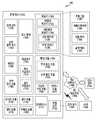
도 1은 다양한 실시 예들에 따른, 네트워크 환경(100) 내의 전자 장치(101)의 블록도이다. 도 1을 참고하면, 네트워크 환경(100)에서 전자 장치(101)는 제1 네트워크(198)(예: 근거리 무선 통신 네트워크)를 통하여 전자 장치(102)와 통신하거나, 또는 네트워크(199)(예: 원거리 무선 통신 네트워크)를 통하여 전자 장치(104) 또는 서버(108)와 통신할 수 있다. 일 실시 예에 따르면, 전자 장치(101)는 서버(108)를 통하여 전자 장치(104)와 통신할 수 있다. 일 실시 예에 따르면, 전자 장치(101)는 프로세서(120), 메모리(130), 입력 장치(150), 음향 출력 장치(155), 표시 장치(160), 오디오 모듈(170), 센서 모듈(176), 인터페이스(177), 햅틱 모듈(179), 카메라 모듈(180), 전력 관리 모듈(188), 배터리(189), 통신 모듈(190), 가입자 식별 모듈(196), 또는 안테나 모듈(197)을 포함할 수 있다. 어떤 실시 예에서는, 전자 장치(101)에는, 이 구성요소들 중 적어도 하나(예: 표시 장치(160) 또는 카메라 모듈(180))가 생략되거나, 하나 이상의 다른 구성 요소가 추가될 수 있다. 어떤 실시 예에서는, 이 구성요소들 중 일부들은 하나의 통합된 회로로 구현될 수 있다. 예를 들면, 센서 모듈(176)(예: 지문 센서, 홍채 센서, 또는 조도 센서)은 표시 장치(160)(예: 디스플레이)에 임베디드된 채 구현될 수 있다1 is a block diagram of an
프로세서(120)는, 예를 들면, 소프트웨어(예: 프로그램(140))를 실행하여 프로세서(120)에 연결된 전자 장치(101)의 적어도 하나의 다른 구성요소(예: 하드웨어 또는 소프트웨어 구성요소)을 제어할 수 있고, 다양한 데이터 처리 또는 연산을 수행할 수 있다. 일 실시 예에 따르면, 데이터 처리 또는 연산의 적어도 일부로서, 프로세서(120)는 다른 구성요소(예: 센서 모듈(176) 또는 통신 모듈(190))로부터 수신된 명령 또는 데이터를 휘발성 메모리(132)에 로드하고, 휘발성 메모리(132)에 저장된 명령 또는 데이터를 처리하고, 결과 데이터를 비휘발성 메모리(134)에 저장할 수 있다. 일 실시 예에 따르면, 프로세서(120)는 메인 프로세서(121)(예: 중앙 처리 장치 또는 어플리케이션 프로세서), 및 이와는 독립적으로 또는 함께 운영 가능한 보조 프로세서(123)(예: 그래픽 처리 장치, 이미지 시그널 프로세서, 센서 허브 프로세서, 또는 커뮤니케이션 프로세서)를 포함할 수 있다. 추가적으로 또는 대체적으로, 보조 프로세서(123)은 메인 프로세서(121)보다 저전력을 사용하거나, 또는 지정된 기능에 특화되도록 설정될 수 있다. 보조 프로세서(123)는 메인 프로세서(121)와 별개로, 또는 그 일부로서 구현될 수 있다.The
보조 프로세서(123)는, 예를 들면, 메인 프로세서(121)가 인액티브(예: 슬립) 상태에 있는 동안 메인 프로세서(121)를 대신하여, 또는 메인 프로세서(121)가 액티브(예: 어플리케이션 실행) 상태에 있는 동안 메인 프로세서(121)와 함께, 전자 장치(101)의 구성요소들 중 적어도 하나의 구성요소(예: 표시 장치(160), 센서 모듈(176), 또는 통신 모듈(190))와 관련된 기능 또는 상태들의 적어도 일부를 제어할 수 있다. 일 실시 예에 따르면, 보조 프로세서(123)(예: 이미지 시그널 프로세서 또는 커뮤니케이션 프로세서)는 기능적으로 관련 있는 다른 구성 요소(예: 카메라 모듈(180) 또는 통신 모듈(190))의 일부로서 구현될 수 있다. The
메모리(130)는, 전자 장치(101)의 적어도 하나의 구성요소(예: 프로세서(120) 또는 센서모듈(176))에 의해 사용되는 다양한 데이터를 저장할 수 있다. 데이터는, 예를 들어, 소프트웨어(예: 프로그램(140)) 및, 이와 관련된 명령에 대한 입력 데이터 또는 출력 데이터를 포함할 수 있다. 메모리(130)는, 휘발성 메모리(132) 또는 비휘발성 메모리(134)를 포함할 수 있다. The memory 130 may store various data used by at least one component of the electronic device 101 (eg, the
프로그램(140)은 메모리(130)에 소프트웨어로서 저장될 수 있으며, 예를 들면, 운영 체제(142), 미들 웨어(144) 또는 어플리케이션(146)을 포함할 수 있다. The program 140 may be stored as software in the memory 130, and may include, for example, an operating system 142, middleware 144, or an
입력 장치(150)는, 전자 장치(101)의 구성요소(예: 프로세서(120))에 사용될 명령 또는 데이터를 전자 장치(101)의 외부(예: 사용자)로부터 수신할 수 있다. 입력 장치(150)은, 예를 들면, 마이크, 마우스, 키보드, 또는 디지털 펜(예:스타일러스 펜)을 포함할 수 있다. The
음향 출력 장치(155)는 음향 신호를 전자 장치(101)의 외부로 출력할 수 있다. 음향 출력 장치(155)는, 예를 들면, 스피커 또는 리시버를 포함할 수 있다. 스피커는 멀티미디어 재생 또는 녹음 재생과 같이 일반적인 용도로 사용될 수 있고, 리시버는 착신 전화를 수신하기 위해 사용될 수 있다. 일 실시 예에 따르면, 리시버는 스피커와 별개로, 또는 그 일부로서 구현될 수 있다.The
표시 장치(160)는 전자 장치(101)의 외부(예: 사용자)로 정보를 시각적으로 제공할 수 있다. 표시 장치(160)은, 예를 들면, 디스플레이, 홀로그램 장치, 또는 프로젝터 및 해당 장치를 제어하기 위한 제어 회로를 포함할 수 있다. 일 실시 예에 따르면, 표시 장치(160)는 터치를 감지하도록 설정된 터치 회로(touch circuitry), 또는 상기 터치에 의해 발생되는 힘의 세기를 측정하도록 설정된 센서 회로(예: 압력 센서)를 포함할 수 있다. The display device 160 may visually provide information to the outside of the electronic device 101 (eg, a user). The display device 160 may include, for example, a display, a hologram device, or a projector and a control circuit for controlling the device. According to an embodiment, the display device 160 may include a touch circuitry configured to sense a touch, or a sensor circuit (eg, a pressure sensor) configured to measure the strength of the force generated by the touch. have.
오디오 모듈(170)은 소리를 전기 신호로 변환시키거나, 반대로 전기 신호를 소리로 변환시킬 수 있다. 일 실시 예에 따르면, 오디오 모듈(170)은, 입력 장치(150)를 통해 소리를 획득하거나, 음향 출력 장치(155), 또는 전자 장치(101)와 직접 또는 무선으로 연결된 외부 전자 장치(예: 전자 장치(102)) (예: 스피커 또는 헤드폰))를 통해 소리를 출력할 수 있다.The
센서 모듈(176)은 전자 장치(101)의 작동 상태(예: 전력 또는 온도), 또는 외부의 환경 상태(예: 사용자 상태)를 감지하고, 감지된 상태에 대응하는 전기 신호 또는 데이터 값을 생성할 수 있다. 일 실시 예에 따르면, 센서 모듈(176)은, 예를 들면, 제스처 센서, 자이로 센서, 기압 센서, 마그네틱 센서, 가속도 센서, 그립 센서, 근접 센서, 컬러 센서, IR(infrared) 센서, 생체 센서, 온도 센서, 습도 센서, 또는 조도 센서를 포함할 수 있다. The
인터페이스(177)는 전자 장치(101)이 외부 전자 장치(예: 전자 장치(102))와 직접 또는 무선으로 연결되기 위해 사용될 수 있는 하나 이상의 지정된 프로토콜들을 지원할 수 있다. 일 실시 예에 따르면, 인터페이스(177)는, 예를 들면, HDMI(high definition multimedia interface), USB(universal serial bus) 인터페이스, SD카드 인터페이스, 또는 오디오 인터페이스를 포함할 수 있다.The
연결 단자(178)는, 그를 통해서 전자 장치(101)가 외부 전자 장치(예: 전자 장치(102))와 물리적으로 연결될 수 있는 커넥터를 포함할 수 있다. 일 실시 예에 따르면, 연결 단자(178)은, 예를 들면, HDMI 커넥터, USB 커넥터, SD 카드 커넥터, 또는 오디오 커넥터(예: 헤드폰 커넥터)를 포함할 수 있다.The
햅틱 모듈(179)은 전기적 신호를 사용자가 촉각 또는 운동 감각을 통해서 인지할 수 있는 기계적인 자극(예: 진동 또는 움직임) 또는 전기적인 자극으로 변환할 수 있다. 일 실시 예에 따르면, 햅틱 모듈(179)은, 예를 들면, 모터, 압전 소자, 또는 전기 자극 장치를 포함할 수 있다.The haptic module 179 may convert electrical signals into mechanical stimuli (eg, vibration or movement) or electrical stimuli that the user can perceive through tactile or motor sensations. According to one embodiment, the haptic module 179 may include, for example, a motor, a piezoelectric element, or an electrical stimulation device.
카메라 모듈(180)은 정지 영상 및 동영상을 촬영할 수 있다. 일 실시 예에 따르면, 카메라 모듈(180)은 하나 이상의 렌즈들, 이미지 센서들, 이미지 시그널 프로세서들, 또는 플래시들을 포함할 수 있다.The
전력 관리 모듈(188)은 전자 장치(101)에 공급되는 전력을 관리할 수 있다. 일 실시 예에 따르면, 전력 관리 모듈(388)은, 예를 들면, PMIC(power management integrated circuit)의 적어도 일부로서 구현될 수 있다.The
배터리(189)는 전자 장치(101)의 적어도 하나의 구성 요소에 전력을 공급할 수 있다. 일 실시 예에 따르면, 배터리(189)는, 예를 들면, 재충전 불가능한 1차 전지, 재충전 가능한 2차 전지 또는 연료 전지를 포함할 수 있다.The
통신 모듈(190)은 전자 장치(101)와 외부 전자 장치(예: 전자 장치(102), 전자 장치(104), 또는 서버(108))간의 직접(예: 유선) 통신 채널 또는 무선 통신 채널의 수립, 및 수립된 통신 채널을 통한 통신 수행을 지원할 수 있다. 통신 모듈(190)은 프로세서(120)(예: 어플리케이션 프로세서)와 독립적으로 운영되고, 직접(예: 유선) 통신 또는 무선 통신을 지원하는 하나 이상의 커뮤니케이션 프로세서를 포함할 수 있다. 일 실시 예에 따르면, 통신 모듈(190)은 무선 통신 모듈(192)(예: 셀룰러 통신 모듈, 근거리 무선 통신 모듈, 또는 GNSS(global navigation satellite system) 통신 모듈) 또는 유선 통신 모듈(194)(예: LAN(local area network) 통신 모듈, 또는 전력선 통신 모듈)을 포함할 수 있다. 이들 통신 모듈 중 해당하는 통신 모듈은 제1 네트워크(198)(예: 블루투스, WiFi direct 또는 IrDA(infrared data association) 같은 근거리 통신 네트워크) 또는 네트워크(199)(예: 셀룰러 네트워크, 인터넷, 또는 컴퓨터 네트워크(예: LAN 또는 WAN)와 같은 원거리 통신 네트워크)를 통하여 외부 전자 장치와 통신할 수 있다. 이런 여러 종류의 통신 모듈들은 하나의 구성 요소(예: 단일 칩)으로 통합되거나, 또는 서로 별도의 복수의 구성 요소들(예: 복수 칩들)로 구현될 수 있다. 무선 통신 모듈(192)은 가입자 식별 모듈(196)에 저장된 가입자 정보(예: 국제 모바일 가입자 식별자(IMSI))를 이용하여 제1 네트워크(198) 또는 네트워크(199)와 같은 통신 네트워크 내에서 전자 장치(101)를 확인 및 인증할 수 있다. The communication module 190 is a direct (eg, wired) communication channel or a wireless communication channel between the
안테나 모듈(197)은 신호 또는 전력을 외부(예: 외부 전자 장치)로 송신하거나 외부로부터 수신할 수 있다. 일 실시 예에 따르면, 안테나 모듈은 서브스트레이트(예: PCB) 위에 형성된 도전체 또는 도전성 패턴으로 이루어진 방사체를 포함하는 하나의 안테나를 포함할 수 있다. 일 실시 예에 따르면, 안테나 모듈(197)은 복수의 안테나들을 포함할 수 있다. 이런 경우, 제1 네트워크(198) 또는 네트워크(199)와 같은 통신 네트워크에서 사용되는 통신 방식에 적합한 적어도 하나의 안테나가, 예를 들면, 통신 모듈(190)에 의하여 상기 복수의 안테나들로부터 선택될 수 있다. 신호 또는 전력은 상기 선택된 적어도 하나의 안테나를 통하여 통신 모듈(190)과 외부 전자 장치 간에 송신되거나 수신될 수 있다. 어떤 실시 예에 따르면, 방사체 이외에 다른 부품(예: RFIC)이 추가로 안테나 모듈(197)의 일부로 형성될 수 있다.The
상기 구성요소들 중 적어도 일부는 주변 장치들간 통신 방식(예: 버스, GPIO(general purpose input and output), SPI(serial peripheral interface), 또는 MIPI(mobile industry processor interface))를 통해 서로 연결되고 신호(예: 명령 또는 데이터)를 상호간에 교환할 수 있다.At least some of the components are connected to each other through a communication method between peripheral devices (for example, a bus, a general purpose input and output (GPIO), a serial peripheral interface (SPI), or a mobile industry processor interface (MIPI)). Ex: command or data) can be exchanged with each other.
일 실시 예에 따르면, 명령 또는 데이터는 네트워크(199)에 연결된 서버(108)를 통해서 전자 장치(101)와 외부의 전자 장치(104)간에 송신 또는 수신될 수 있다. 전자 장치(102, 104) 각각은 전자 장치(101)와 동일한 또는 다른 종류의 장치일 수 있다. 일 실시 예에 따르면, 전자 장치(101)에서 실행되는 동작들의 전부 또는 일부는 외부 전자 장치들(102, 104, or 108) 중 하나 이상의 외부 장치들에서 실행될 수 있다. 예를 들면, 전자 장치(101)가 어떤 기능이나 서비스를 자동으로, 또는 사용자 또는 다른 장치로부터의 요청에 반응하여 수행해야 할 경우에, 전자 장치(101)는 기능 또는 서비스를 자체적으로 실행시키는 대신에 또는 추가적으로, 하나 이상의 외부 전자 장치들에게 그 기능 또는 그 서비스의 적어도 일부를 수행하라고 요청할 수 있다. 상기 요청을 수신한 하나 이상의 외부 전자 장치들은 요청된 기능 또는 서비스의 적어도 일부, 또는 상기 요청과 관련된 추가 기능 또는 서비스를 실행하고, 그 실행의 결과를 전자 장치(101)로 전달할 수 있다. 전자 장치(101)는 상기 결과를, 그대로 또는 추가적으로 처리하여, 상기 요청에 대한 응답의 적어도 일부로서 제공할 수 있다. 이를 위하여, 예를 들면, 클라우드 컴퓨팅, 분산 컴퓨팅, 또는 클라이언트-서버 컴퓨팅 기술이 이용될 수 있다. According to an embodiment, the command or data may be transmitted or received between the
도 2는, 무선 연결을 위하여 방향성 빔을 사용하는 네트워크에서 기지국(220)과 전자 장치(101) 간의 무선 통신 연결을 위한 동작의 일 실시 예를 도시한다. 먼저, 상기 기지국(gNB(gNodeB), TRP(transmission reception point))(220)은, 상기 무선 통신 연결을 위하여, 전자 장치(101)와 빔 디텍션(beam detection) 동작을 수행할 수 있다. 도시된 실시 예에서, 빔 디텍션을 위하여, 상기 기지국(220)은, 복수의 송신 빔들, 예를 들어, 방향이 상이한 제1 내지 제5 송신 빔들(231-1 내지 231-5)을 순차적으로 송신함으로써, 적어도 한번의 송신 빔 스위핑(230)을 수행할 수 있다.2 illustrates an embodiment of an operation for wireless communication connection between a
상기 제1 내지 제5 송신 빔들(231-1 내지 231-5)은 적어도 하나의 SS/PBCH BLOCK(synchronization sequences(SS)/ physical broadcast channel(PBCH) Block)을 포함할 수 있다. 상기 SS/PBCH Block 은, 주기적으로 전자 장치(101)의 채널, 또는 빔 세기를 측정하는데 이용될 수 있다.The first to fifth transmission beams 231-1 to 231-5 may include at least one synchronization sequence (SS)/physical broadcast channel (PBCH) block. The SS/PBCH block may be periodically used to measure a channel or beam intensity of the
또 다른 실시 예에서, 제1 내지 제5 송신 빔들(231-1 내지 231-5)은 적어도 하나의 CSI-RS(channel state information-reference signal)을 포함할 수 있다. CSI-RS은 기지국(220)이 유동적(flexible)으로 설정할 수 있는 기준/참조 신호로서 주기적(periodic)/반주기적(semi-persistent) 또는 비주기적(aperiodic)으로 전송될 수 있다. 상기 전자 장치(101)는 상기 CSI-RS를 이용하여 채널, 빔 세기를 측정할 수 있다. In another embodiment, the first to fifth transmission beams 231-1 to 231-5 may include at least one channel state information-reference signal (CSI-RS). The CSI-RS is a reference/reference signal that the
상기 송신 빔들은 선택된 빔 폭을 가지는 방사 패턴을 형성할 수 있다. 예를 들어, 상기 송신 빔들은 제1 빔 폭을 가지는 넓은(broad) 방사 패턴, 또는 상기 제1 빔 폭보다 좁은 제2 빔폭을 가지는 좁은(sharp) 방사 패턴을 가질 수 있다. 예를 들면, SS/PBCH Block을 포함하는 송신 빔들은 CSI-RS를 포함하는 송신 빔 보다 넓은 방사 패턴을 가질 수 있다.The transmission beams may form a radiation pattern having a selected beam width. For example, the transmission beams may have a broad radiation pattern having a first beam width, or a sharp radiation pattern having a second beam width that is narrower than the first beam width. For example, the transmission beams including the SS/PBCH block may have a wider radiation pattern than the transmission beam including the CSI-RS.
상기 전자 장치(101)는, 상기 기지국이(220)이 송신 빔 스위핑(230)을 하는 동안, 수신 빔 스위핑(240)을 할 수 있다. 예를 들면, 전자 장치(101)는 기지국(220)이 첫 번째 송신 빔 스위핑(230)을 수행하는 동안, 제1 수신 빔(245-1)을 제1 방향으로 고정하여 상기 제1 내지 제5 송신 빔들(231-1 내지 231-5) 중 적어도 하나에서 전송되는 SS/PBCH Block의 신호를 수신할 수 있다. 전자 장치(101)는 기지국(220)이 두 번째 송신 빔 스위핑(230)을 수행하는 동안, 제2 수신 빔(245-2)을 제2 방향으로 고정하여 제1 내지 제5 송신 빔들(231-1 내지 231-5)에서 전송되는 SS/PBCH Block의 신호를 수신할 수 있다. 이와 같이, 전자 장치(101)는 수신 빔 스위핑(240)을 통한 신호 수신 동작 결과에 기반하여, 통신 가능한 수신 빔(예: 제2 수신 빔(245-2))과 송신 빔(예: 제3 송신 빔(231-3))을 선택할 수 있다.The
위와 같이, 통신 가능한 송수신 빔들이 결정된 후, 기지국(220)과 전자 장치(101)는 셀 설정을 위한 기본적인 정보들을 송신 및/또는 수신하고, 이를 기반으로 추가적인 빔 운용을 위한 정보를 설정할 수 있다. 예를 들면, 상기 빔 운용 정보는, 설정된 빔에 대한 상세 정보, SS/PBCH Block, CSI-RS 또는 추가적인 기준 신호에 대한 설정 정보를 포함할 수 있다.As described above, after the transmit/receive beams capable of communication are determined, the
또한, 전자 장치(101)는 송신 빔에 포함된 SS/PBCH Block, CSI-RS 중 적어도 하나를 이용하여 채널 및 빔의 세기를 지속적으로 모니터링 할 수 있다. 전자 장치(101)는 상기 모니터링 동작을 이용하여 빔 퀄리티가 좋은 빔을 적응적으로 선택할 수 있다. 선택적으로, 전자 장치(101)의 이동 또는 빔의 차단이 발생하여 통신 연결이 해제되면, 위의 빔 스위핑 동작을 재수행하여 통신 가능한 빔을 결정할 수 있다.Also, the
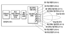
도 3은, 일 실시 예에 따른, 5G 네트워크 통신을 위한 전자 장치(101)의 블록도이다. 상기 전자 장치(101)는, 도 3에 도시된 다양한 부품을 포함할 수 있으나, 도 3에서는, 간략한 설명을 위하여, 프로세서(120), 제2 커뮤니케이션 프로세서(314), 제4 RFIC(328), 적어도 하나의 제3 안테나 모듈(346)을 포함하는 것으로 도시되었다. 3 is a block diagram of an
도시된 실시 예에서, 상기 제3 안테나 모듈(346)은 제1 내지 제4 위상 변환기들(313-1내지 313-4) 및/또는 제1 내지 제 4 안테나 엘리먼트들(317-1 내지 317-4)을 포함할 수 있다. 상기 제1 내지 제 4 안테나 엘리먼트들(317-1 내지 317-4)의 각 하나는 제1 내지 제4 위상 변환기들(313-1내지 313-4) 중 개별적인 하나에 전기적으로 연결될 수 있다. 상기 제1 내지 제 4 안테나 엘리먼트들(317-1 내지 317-4)은 적어도 하나의 안테나 어레이(315)를 형성할 수 있다.In the illustrated embodiment, the third antenna module 346 includes first to fourth phase converters 313-1 to 313-4 and/or first to fourth antenna elements 317-1 to 317- 4). Each one of the first to fourth antenna elements 317-1 to 317-4 may be electrically connected to an individual one of the first to fourth phase converters 313-1 to 313-4. The first to fourth antenna elements 317-1 to 317-4 may form at least one antenna array 315.
상기 제2 커뮤니케이션 프로세서(314)는 제1 내지 제4 위상 변환기들(313-1내지 313-4)을 제어함에 의하여, 제1 내지 제 4 안테나 엘리먼트들(317-1 내지 317-4)을 통하여 송신 및/또는 수신된 신호들의 위상을 제어할 수 있고, 이에 따라 선택된 방향으로 송신 빔 및/또는 수신 빔을 생성 할 수 있다.The
일 실시 예에 따르면, 제3 안테나 모듈(346)은 사용되는, 안테나 엘리먼트의 수에 따라 위에 언급된 넓은 방사 패턴의 빔(351)(이하 "넓은 빔") 또는 좁은 방사 패턴의 빔(352)(이하 "좁은 빔")을 형성할 수 있다. 예를 들어, 제3 안테나 모듈(346)은, 제1 내지 제 4 안테나 엘리먼트들(317-1 내지 317-4)을 모두 사용할 경우 좁은 빔(352)을 형성할 수 있고, 제1 안테나 엘리먼트(317-1)와 제2 안테나 엘리먼트(317-2) 만을 사용할 경우 넓은 빔(351)을 형성할 수 있다. 상기 넓은 빔(351)은 좁은 빔(352) 보다 넓은 coverage를 가지나, 적은 안테나 이득(antenna gain)을 가지므로 빔 탐색 시 더 효과적일 수 있다. 반면에, 좁은 빔(352)은 넓은 빔(351) 보다 좁은 coverage를 가지나 안테나 이득이 더 높아서 통신 성능을 향상 시킬 수 있다.According to one embodiment, the third antenna module 346 is used in accordance with the number of antenna elements, the above-mentioned wide radiation pattern beam 351 (hereinafter "wide beam") or narrow radiation pattern beam 352 (Hereinafter referred to as "narrow beam"). For example, the third antenna module 346 may form a narrow beam 352 when all of the first to fourth antenna elements 317-1 to 317-4 are used, and the first antenna element ( When only the 317-1) and the second antenna element 317-2 are used, a wide beam 351 can be formed. The wide beam 351 has a wider coverage than the narrow beam 352, but has less antenna gain, so it may be more effective when searching for a beam. On the other hand, the narrow beam 352 has a narrower coverage than the wide beam 351, but the antenna gain is higher, thereby improving communication performance.
일 실시 예에 따르면, 상기 제2 커뮤니케이션 프로세서(314)는 센서 모듈(176)(예: 9축 센서, grip sensor, 또는 GPS)을 빔 탐색에 활용할 수 있다. 예를 들면, 전자 장치(101)는 센서 모듈(176)을 이용하여 전자 장치(101)의 위치 및/또는 움직임을 기반으로 빔의 탐색 위치 및/또는 빔 탐색 주기를 조절 할 수 있다. 또 다른 예로, 전자 장치(101)가 사용자에게 파지되는 경우, grip sensor를 이용하여, 사용자의 파지 부분을 파악함으로써, 복수의 제3 안테나 모듈(346) 들 중 통신 성능이 보다 좋은 안테나 모듈을 선택할 수 있다. According to one embodiment, the
본 발명의 다양한 실시 예들에 따르면, 전자 장치(예: 전자 장치(101), 기지국(220))는, 메모리(예: 메모리(130)), 상기 메모리와 동작적으로 연결된 프로세서(예: 프로세서(120))를 포함하며, 상기 프로세서는, 수신 빔들 중 일부를 통해 동기 신호 또는 기준 신호를 수신하고, 상기 수신 빔들 중 일부에 대한 측정 결과에 기반하여 상기 수신 빔들에 대한 수신 신호 품질 값들을 결정하고, 상기 수신 신호 품질 값들에 기반하여 최적의 수신 빔을 결정할 수 있다.According to various embodiments of the present invention, an electronic device (eg, the
본 발명의 다양한 실시 예들에 따르면, 상기 프로세서(예: 프로세서(120))는, 상기 수신 빔들 간 상관도에 기반하여 상기 수신 신호 품질 값들을 예측할 수 있다.According to various embodiments of the present invention, the processor (eg, the processor 120) may predict the received signal quality values based on the correlation between the received beams.
본 발명의 다양한 실시 예들에 따르면, 상기 수신 빔들 중 일부는, 상기 일부에 속하는 수신 빔들 간 상관도들이 최소화되도록 결정될 수 있다.According to various embodiments of the present invention, some of the received beams may be determined such that correlations between received beams belonging to the part are minimized.
본 발명의 다양한 실시 예들에 따르면, 상기 프로세서(예: 프로세서(120))는, 제1 행렬을 결정하고, 상기 제1 행렬을 역-기저 변환함으로써 제2 행렬을 결정하고, 상기 제2 행렬에 포함된 원소들의 값들을 확인할 수 있다.According to various embodiments of the present invention, the processor (eg, the processor 120) determines a first matrix, determines a second matrix by inverse-base transforming the first matrix, and stores the second matrix in the second matrix. You can check the values of the elements included.
본 발명의 다양한 실시 예들에 따르면, 상기 프로세서(예: 프로세서(120))는, 상기 제2 행렬에 포함된 원소들 중 상기 수신 빔들 중 일부에 속하는 적어도 하나의 수신 빔의 위치에 대응하는 적어도 하나의 원소의 값 및 상기 수신 빔들 중 일부에 대한 적어도 하나의 수신 신호 품질 값 간 오차를 최소화하도록 상기 제1 행렬을 결정할 수 있다.According to various embodiments of the present invention, the processor (eg, the processor 120) may include at least one corresponding to a position of at least one received beam belonging to a part of the received beams among elements included in the second matrix. The first matrix may be determined to minimize an error between an element value of and at least one received signal quality value for some of the received beams.
본 발명의 다양한 실시 예들에 따르면, 상기 프로세서(예: 프로세서(120))는, 상기 제1 행렬의 원소들 중 일부 원소들의 값들을 추정하고, 나머지 원소들의 값들을 0으로 결정할 수 있다.According to various embodiments of the present invention, the processor (eg, the processor 120) may estimate values of some of the elements of the first matrix and determine values of the remaining elements as 0.
본 발명의 다양한 실시 예들에 따르면, 상기 프로세서(예: 프로세서(120))는, 좌측 첫번째 및 상단 첫번째의 원소로부터 시작하여 지그재그 순서로 상기 일부 원소들의 값들을 추정할 수 있다.According to various embodiments of the present invention, the processor (eg, the processor 120) may estimate values of some of the elements in a zigzag order, starting from the first left and top first elements.
본 발명의 다양한 실시 예들에 따르면, 상기 일부 원소들의 개수는, 상기 수신 빔들 간 상관도에 기반하여 예측된 수신 신호 품질 값들 중 최대 값에 대응하는 제1 수신 빔에 대하여 측정된 제1 수신 신호 품질 값이, 상기 수신 빔들 중 일부에 대한 측정 결과에 포함된 수신 신호 품질 값들 중 최대 값에 대응하는 제2 수신 빔에 대하여 측정된 제2 수신 신호 품질 값보다 작은 경우의 발생 빈도에 기반하여 조절될 수 있다. According to various embodiments of the present invention, the number of some of the elements is the first received signal quality measured for the first received beam corresponding to the maximum value among the predicted received signal quality values based on the correlation between the received beams The value is adjusted based on the frequency of occurrence when the second received beam quality value measured for the second received beam corresponding to the maximum value among the received signal quality values included in the measurement result for some of the received beams Can.
본 발명의 다양한 실시 예들에 따르면, 상기 프로세서(예: 프로세서(120))는, 상기 수신 신호 품질 값들 중 최대 값에 대응하는 제1 수신 빔을 이용하여 동기 신호 또는 기준 신호를 수신하고, 상기 동기 신호 또는 상기 기준 신호에 대한 측정을 수행함으로써, 상기 제1 수신 빔에 대한 제1 수신 신호 품질 값을 확인하고, 상기 제1 수신 신호 품질 값에 기반하여 상기 최적의 수신 빔을 결정할 수 있다.According to various embodiments of the present invention, the processor (eg, processor 120) receives a synchronization signal or a reference signal using a first reception beam corresponding to a maximum value among the received signal quality values, and the synchronization By performing measurement on the signal or the reference signal, the first received signal quality value for the first received beam may be checked, and the optimal received beam may be determined based on the first received signal quality value.
본 발명의 다양한 실시 예들에 따르면, 상기 프로세서(예: 프로세서(120))는, 상기 수신 빔들 중 일부에 대한 측정 결과에 포함되는 수신 신호 품질 값들 중 최대 값에 대응하는 제2 수신 빔에 대한 제2 수신 신호 품질 값을 확인하고, 상기 제1 수신 신호 품질 값 보다 상기 제2 수신 신호 품질 값이 크면, 상기 제1 수신 빔을 상기 최적의 수신 빔으로서 선택하고, 상기 제1 수신 신호 품질 값 보다 상기 제2 수신 신호 품질 값이 작거나 같으면, 상기 제2 수신 빔을 상기 최적의 수신 빔으로서 선택할 수 있다.According to various embodiments of the present invention, the processor (eg, processor 120) may include a second received beam corresponding to a maximum value among received signal quality values included in a measurement result of some of the received beams. 2 Check the received signal quality value, and if the second received signal quality value is greater than the first received signal quality value, select the first received beam as the optimal received beam, than the first received signal quality value If the second received signal quality value is less than or equal to, the second received beam may be selected as the optimal received beam.
안테나 어레이(315)의 위상 변화를 이용하여 다양한 빔들이 형성될 수 있다. 다양한 실시 예들에 따르면, 기지국(예: 도 2의 기지국(220))에서의 송수신뿐만 아니라 전자 장치(101)에서의 송수신에도 빔포밍이 사용될 수 있다. 신호의 도달 거리를 늘리기 위해 좁은 빔 폭으로 빔포밍이 수행될 수 있으며, 빔 폭이 좁기 때문에 기지국의 송신 빔과 전자 장치(101)의 수신 빔을 모두 조정하여 최적의 송수신 빔 쌍을 찾아야 효율적인 통신이 가능할 수 있다. 송신 빔 또는 수신 빔을 찾는 절차는 '빔 탐색'이라 지칭될 수 있다.Various beams may be formed using the phase change of the antenna array 315. According to various embodiments, beamforming may be used not only for transmission and reception at the base station (eg, the
빔 탐색을 위해, 기지국(220)은, 이하 도 4의 일 실시 예와 같이, SSB(synchronization signal/physical broadcast channel block)를 반복적으로 송신할 수 있다. For the beam search, the
도 4는 다양한 실시 예들에 따른 5G 네트워크에서 기지국의 SSB 송신에 대한 예이다. 4 is an example of SSB transmission of a base station in a 5G network according to various embodiments.
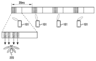
도 4는 기지국에서 4개의 서로 다른 송신 빔을 운용하는 경우 4개의 SSB를 서로 다른 빔으로 전송하는 예이다. 도 4를 참고하면, 기지국(220)은 형성 가능한 송신 빔들의 개수(예: 4개)만큼의 SSB들을 하나의 집합(set)으로 하여 주기적으로 송신할 수 있다. 하나의 집합의 SSB들은 'SSB 버스트(burst)' 또는 'SSB 집합'이라 지칭될 수 있다. SSB 집합의 전송 주기는 다양하게 설정될 수 있으며, 예를 들어, 20ms로 설정될 수 있다.4 is an example of transmitting four SSBs in different beams when the base station operates four different transmit beams. Referring to FIG. 4, the
일 실시예에 따르면, 각 SSB는 각 송신 빔에 대응할 수 있다. 각 SSB는 대응하는 송신 빔에 대한 식별 정보를 포함할 수 있다. 예를 들어, 송신 빔에 대한 식별 정보는 SSB의 인덱스일 수 있다, SSB의 인덱스는 SSB에 포함되는 방송 채널을 통해 송신되는 시스템 정보 또는 DMRS(demodulation reference signal) 중 적어도 하나를 이용하여 표현될 수 있다.According to an embodiment, each SSB may correspond to each transmission beam. Each SSB may include identification information for a corresponding transmission beam. For example, the identification information for the transmission beam may be the index of the SSB, the index of the SSB may be expressed using at least one of system information or a demodulation reference signal (DMRS) transmitted through a broadcast channel included in the SSB. have.
도 5는 다양한 실시 예들에 따른 5G 네트워크에서 전자 장치의 SSB 수신에 대한 예이다. 도 5는 전자 장치(101)에서 4개의 수신 빔들을 운용하는 경우 최적의 송수신 빔 쌍을 찾기 위한 동작의 예이다. 5 is an example of SSB reception of an electronic device in a 5G network according to various embodiments. 5 is an example of an operation for finding an optimal transmission/reception beam pair when the four reception beams are operated by the
도 5를 참고하면, 일 실시예에 따른 전자 장치(101)는 각 SSB를 수신 및 측정하고, 측정 결과에 기반하여 기지국(220)의 송신 빔과 전자 장치(101)의 수신 빔을 결정할 수 있다. 일 실시예에 따르면, SSB 집합의 송신 주기는 일반적으로 20 ms로 설정될 수 있다. 다른 예로, SSB 집합의 송신 주기는 5 내지 160 ms의 범위에서 조절될 수 있다. 전자 장치(101)는 각 SSB 집합에 대하여 형성 가능한 수신 빔을 하나씩 이용하여 SSB 집합에 포함된 신호에 대한 측정을 수행하고, SSB 집합의 송신을 위해 사용된 기지국(220)의 송신 빔들에 대한 최적의 수신 빔을 찾을 수 있다. 이하 설명되는 다양한 실시 예들에 따라, 전자 장치(101)는 일부 수신 빔들에 대한 측정 결과를 이용하여 최적의 수신 빔을 찾음으로써, 모든 수신 빔들의 개수를 탐색하는 경우보다 짧은 시간 동안, 적은 전력 소모만으로 최적의 수신 빔을 결정할 수 있다.Referring to FIG. 5, the
6은 다양한 실시 예들에 따른 5G 네트워크에서 기지국의 수신 빔 결정을 위한 수신 빔 스위핑(beam sweeping)의 예이다. 도 6을 참고하면, 일 실시예에 따른 전자 장치(101)의 수신 빔뿐만 아니라, 상향링크 통신을 위한 기지국(예: 도 2의 기지국(220))의 수신 빔을 결정하는 절차가 수행될 수 있다. 예를 들어, 상향링크 채널 및 하향링크 채널의 상호성(reciprocity)이 보장됨으로 인해 송신 시 이용한 빔을 수신 시 에도 이용할 수 있는 경우, 전자 장치(101)의 최적의 수신 빔과 동일한 방향의 송신 빔 및 기지국의 최적의 송신 빔과 동일한 방향의 수신 빔이 상향링크 통신을 위한 최적의 송신 빔 및 수신 빔으로 사용될 수 있다. 다른 예로, 채널 상호성이 확보되지 아니하는 경우, 별도의 빔 결정 절차가 요구될 수 있다. 6 is an example of reception beam sweeping for determining a reception beam of a base station in a 5G network according to various embodiments. Referring to FIG. 6, a procedure for determining a reception beam of a base station (eg, the
일 실시예에 따르면, 전자 장치(101)는 적어도 하나의 송신 빔(예: 송신 빔#0)을 이용하여 SRS(sounding reference signal)들(예: SRS#0, SRS#1, SRS#2, SRS#3)을 송신할 수 있다. 각 SRS는 하나의 송신 빔(예: 송신 빔#2)을 통해 서로 다른 시간 또는 주파수 자원들(602a, 602b, 602c, 602d)에서 송신될 수 있다. 기지국(220)은 하나의 송신 빔을 이용하여 송신된 SRS들(예: SRS#0, SRS#1, SRS#2, SRS#3) 각각을 다른 수신 빔들(예: 수신 빔 #0, 수신 빔 #1, 수신 빔 #2, 수신 빔 #3)을 이용하여 수신할 수 있다. 기지국(220)은 서로 다른 자원들(602a, 602b, 602c, 602d)에서 송신되는 각 SRS마다 서로 다른 수신 빔들을 적용하고, 수신 신호 품질을 측정하고, 측정된 수신 신호 품질에 기반하여 전자 장치(101)의 하나의 송신 빔에 대응하는 최적의 수신 빔을 결정할 수 있다. 도 6과 같은 동작이 전자 장치(101)에서 형성 가능한 송신 빔들의 개수만큼 반복되면, 상향링크 통신을 위한 최적의 빔 쌍이 결정될 수 있다. According to an embodiment, the
전자 장치(101)가 고속으로 이동하는 상황이 아닌 이상, SSB 집합 또는 SRS들의 전송 주기 당 전자 장치(101)의 이동 거리에 비해 기지국 및 전자 장치(101) 사이의 거리가 더 클 수 있다. 그러므로, 최적의 빔 쌍으로 선택된 기지국의 송신 빔 또는 수신 빔은 크게 변화하지 아니할 수 있다. 예를 들어, 전자 장치(101) 및 기지국의 거리가 30m일 경우, 전자 장치(101)가 20 ms 동안 100 km/h로 이동하더라도 기지국의 송신 빔 또는 수신 빔의 방위각 변화량은 1˚일 수 있고, 기지국의 송신 빔 또는 수신 빔은 자주 바뀌지 않는다고 가정할 수 있다. 다른 예로, 사용자가 전자 장치(101)을 사용하면서 다양한 자세를 취할 수 있으므로, 전자 장치(101)의 수신 빔 또는 송신 빔은 크게 변화할 수 있다. Unless the
사용자가 전자 장치(101)을 사용하는 자세가 변화하는 경우, 전자 장치(101) 및 기지국 사이의 각도가 변화하고, 기존에 설정되었던 최적의 수신 빔은 더 이상 최적이 아니게 될 수 있다. 본 발명의 다양한 실시 예들에 따르면, 전자 장치(101)는 형성 가능한 모든 수신 빔들의 개수보다 적은 개수의 수신 빔들을 사용하여 수신 신호 품질을 측정한 뒤, 기저 변환(change of basis)을 이용하여 적은 개수의 기저(basis)만으로 최적의 수신 빔 위치 및 세기를 예측할 수 있다. 이를 통해, 전류 소모 및 검색 시간이 절감될 수 있다. When the posture of the user using the
이하 설명의 편의를 위해, 전자 장치(101)의 수신 빔을 결정하는 경우가 예로서 설명된다. 그러나, 후술하는 다양한 실시 예들은 상향링크 통신을 위한 기지국의 수신 빔을 결정하기 위해 실시될 수도 있다. For convenience of description, a case in which the reception beam of the
도 7은 다양한 실시 예들에 따른 전자 장치의 수신 빔에 따른 수신 신호 품질 변화의 예이다. 도 7을 참고하면, 일 실시예에 따른 전자 장치(예: 도 1의 전자 장치(101))에서 형성 가능한 NR개의 수신 빔들이 존재하는 경우, 각 수신 빔은 3차원 좌표 상의 단위 크기를 갖는 방향 벡터로 표현될 수 있다. 특정 송신 빔에 대한 각 수신 빔의 수신 신호 품질을 측정하면, 서로 인접한 수신 빔 사이에는 수신 신호 품질의 상관도(correlation)가 크며, 서로 멀리 떨어진 수신 빔 사이에는 상관도가 작을 수 있다. 두 수신 빔들 간 인접도는 방향 벡터 사이 각도의 절대값의 대소에 따라 결정될 수 있다. 7 is an example of a change in reception signal quality according to a reception beam of an electronic device according to various embodiments of the present disclosure. Referring to FIG. 7, when there are NR receive beams that can be formed in an electronic device (for example, the
예를 들어, 원점 기준으로 [-60˚, +60˚] 구간을 6개 빔들을 이용하여 탐색하는 전자 장치(101)을 가정했을 때, 이하 도 7과 같이, 특정 송신 빔에 대하여 어느 하나의 수신 빔에서 최대의 수신 세기 값이 관측되고, 그 수신 빔에서 멀어질수록 낮은 수신 세기가 관측될 수 있다. 수신 빔 각도 약 +13˚에서 최대의 수신 신호 품질 -70dBm이 관측되고, 약 +13˚에서 멀어질수록 관측되는 수신 신호 품질이 낮아질 수 있다. 가장 큰 차이를 가지는 -60˚의 경우, 수신 신호 품질은 최소값인 약 -87dBm일 수 있다.For example, assuming that the
도 8은 다양한 실시 예들에 따른 전자 장치에서 최적의 수신 빔을 결정하기 위한 흐름도(800)이다. 8 is a
도 8에 예시된 흐름도(800)의 동작 주체는 전자 장치(101) 또는 전자 장치(101)의 구성요소(예: 도 1의 프로세서(120))로 이해될 수 있다.The subject of operation of the
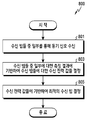
도 8을 참고하면, 일 실시 예에 따라, 동작 801에서, 전자 장치(101)(예: 도 1의 프로세서(120))는 수신 빔들 중 일부를 통해 동기 신호(예: PSS(primary synchronization signal) 또는 SSS(secondary synchronization signal))를 수신할 수 있다. 동기 신호는 SSB에 포함된 수신 신호 품질 측정을 위한 신호의 일 예이다. 동기 신호를 대체하여 또는 병행하여, 전자 장치는 SSB에 포함된 PBCH 내의 기준 신호(reference signal)를 수신할 수 있다. 수신 빔들 중 일부는 미리 정의되거나, 또는 적응적으로 선택될 수 있다. 전자 장치(101)는 수신 빔들 중 일부인 적어도 하나의 수신 빔을 이용하여 수신된 적어도 하나의 동기 신호에 대한 측정 결과(예: 수신 신호 품질 값들)을 획득할 수 있다.Referring to FIG. 8, according to an embodiment, in
일 실시 예에 따라, 동작 803에서, 전자 장치(101)는 수신 빔들 중 일부에 대한 측정 결과에 기반하여 수신 빔들에 대한 수신 신호 품질 값들을 결정할 수 있다. 일부 적어도 하나의 수신 빔에 대한 측정 결과로부터 결정되는 수신 빔들에 대한 수신 신호 품질 값들은 예측된 값들로 이해될 수 있다. 예측을 통해, 동기 신호를 수신하기 위해 사용된 수신 빔들(예: 동작 801에서 사용된 적어도 하나의 수신 빔)의 개수보다 더 많은 수신 빔들(예: 전체 수신 빔들)에 대한 수신 신호 품질 값들이 결정될 수 있다.According to an embodiment, in
일 실시 예에 따라, 동작 805에서, 전자 장치(101)는 수신 신호 품질 값들에 기반하여 최적의 수신 빔을 결정할 수 있다. 예를 들어, 전자 장치(101)는 수신 빔들 간 상관도에 기반하여 적어도 하나의 수신 신호 품질 값을 예측할 수 있다. 전자 장치(101)는 측정된 적어도 하나의 수신 신호 품질 값 또는 예측된 적어도 하나의 수신 신호 품질 값에 기반하여 최적의 수신 빔을 결정할 수 있다.According to an embodiment, in
도 8을 참고하여 설명한 일 실시 예에 따라, 전자 장치는 최적의 수신 빔을 결정할 수 있다. 도 8과 같은 동작들은 다양한 상황에서 수행될 수 있다. 예를 들어, 도 8과 같은 동작들은 최초로 빔 쌍을 결정하는 경우, 또는 빔 쌍 중 적어도 하나를 변경하고자 하는 경우에 수행될 수 있다.According to an embodiment described with reference to FIG. 8, the electronic device may determine an optimal reception beam. The operations as shown in FIG. 8 can be performed in various situations. For example, the operations shown in FIG. 8 may be performed when determining a beam pair for the first time or when changing at least one of the beam pairs.
일 실시 예에 따라, 도 8과 같은 동작들은 전자 장치가 기지국에 초기 접속(initial access)하는 경우에 수행될 수 있다. 이 경우, 전자 장치는 기지국 송신 신호에 대한 최적 수신 빔을 검출하고, 하향링크 동기를 획득할 수 있다. 예를 들어, 전자 장치는 에너지 검출을 통해 기지국이 사용하는 주파수 대역을 확인하고, 래스터(raster) 단위로 동기 신호의 검출을 시도함으로써 하향링크 동기를 획득할 수 있다. 기지국의 송신 빔도 함께 결정하고자 하는 경우, 전자 장치는 복수의 송신 빔들에 대하여 도 8과 같은 동작들을 반복하고, 최대의 수신 신호 품질 값을 제공하는 송신 빔을 선택할 수 있다.According to an embodiment, operations such as FIG. 8 may be performed when the electronic device performs initial access to a base station. In this case, the electronic device may detect an optimal reception beam for the base station transmission signal and acquire downlink synchronization. For example, the electronic device may acquire downlink synchronization by identifying a frequency band used by the base station through energy detection and attempting to detect a synchronization signal in a raster unit. If the transmission beam of the base station is also determined together, the electronic device may repeat the operations as shown in FIG. 8 for a plurality of transmission beams and select a transmission beam that provides the maximum received signal quality value.
다른 실시 예에 따라, 도 8과 같은 동작들은 통신 중 수신 빔을 재선택하는 경우에 수행될 수 있다. 예를 들어, 통신 품질의 열화, 링크 실패(link failure)의 검출, 패킷 오류율 증가 중 어느 하나에 의해 수신 빔의 재선택이 트리거링될 수 있다. 도 8과 같이 일부 수신 빔에 대한 측정만을 수행함으로써, 수신 빔의 재선택이 빠르게 이루어질 수 있다.According to another embodiment, operations as shown in FIG. 8 may be performed when the reception beam is reselected during communication. For example, reselection of the reception beam may be triggered by any one of deterioration of communication quality, detection of link failure, and increase in packet error rate. As shown in FIG. 8, re-selection of the reception beam can be quickly performed by performing measurement on only some reception beams.
또 다른 실시 예에 따라, 도 8과 같은 동작들은 통신 중 수신 빔을 추적(tracking)하는 경우에 수행될 수 있다. 예를 들어, SSB 집합의 송신 주기가 도래한 경우, 통신 품질의 열화가 없더라도, 전자 장치는 도 8과 같은 동작들을 수행함으로써 더 우수한 품질을 제공하는 수신 빔이 존재하는지 여부를 확인할 수 있다. 이 경우, 동작 801에서 사용되는 일부 수신 빔으로서, 전자 장치는 현재 사용 중인 수신 빔을 중심으로 주변의 적어도 하나의 수신 빔을 선택할 수 있다. 이를 통해, 하나의 수신 빔보다 넓은 범위가 관측됨으로써, 최적의 수신 빔이 지속적으로 추적될 수 있다.According to another embodiment, operations such as FIG. 8 may be performed when tracking a received beam during communication. For example, when the transmission period of the SSB set arrives, even if there is no deterioration in communication quality, the electronic device may check whether a reception beam providing better quality exists by performing the operations as shown in FIG. 8. In this case, as some received beams used in
도 8을 참고하여 설명한 바와 같이, 전자 장치는 수신 빔들 중 일부에 대한 수신 신호 품질 값들을 이용하여 모든 수신 빔들에 대한 수신 신호 품질 값들을 획득할 수 있다. 예를 들어, NR개 수신 빔들 중 NS개(NS≤NR)의 수신 빔들이 측정을 위해 사용될 수 있다. NR개 수신 빔들 중 샘플링된 NS개의 수신 빔들을 이용하여 전체 공간에 대한 정보를 얻으려면, 최대한 서로 상관도가 작은 빔을 선택하는 것이 바람직할 수 있다. 이하 도 9를 참고하여, 수신 빔들 간 상관도에 기반하여 선택된 수신 빔들을 이용하여 동기 신호를 수신하는 일 실시 예가 설명된다.As described with reference to FIG. 8, the electronic device may acquire received signal quality values for all received beams by using received signal quality values for some of the received beams. For example, of the NR reception beams, NS (NS≦NR) reception beams may be used for measurement. In order to obtain information about the entire space using the sampled NS received beams among the NR received beams, it may be desirable to select a beam having a small correlation with each other as much as possible. Hereinafter, an embodiment of receiving a synchronization signal using selected reception beams based on a correlation between reception beams will be described with reference to FIG. 9.
도 9는 다양한 실시 예들에 따른 전자 장치에서 동기 신호를 수신하기 위한 흐름도(900)이다. 9 is a
도 10은 다양한 실시 예들에 따른 전자 장치에서 측정을 위해 선택된 수신 빔들의 예이다. 10 is an example of received beams selected for measurement in an electronic device according to various embodiments of the present disclosure.
도 9에 예시된 흐름도(900)의 동작 주체는 전자 장치(101) 또는 전자 장치(101)의 구성요소(예: 도 1의 프로세서(120))로 이해될 수 있다.The operating subject of the
도 9 및 도 10을 참고하면, 일 실시 예에 따라, 동작 901에서, 전자 장치(101)(예: 도 1의 프로세서(120))는 수신 빔들 간 상관도를 확인할 수 있다. 수신 빔들 간 상관도는 수신 빔들 각각의 지향 각도에 기반하여 확인할 수 있다. 예를 들어, 2개의 수신 빔들 간 상관도는 2개의 수신 빔들의 지향 각도들의 차이에 따라 달라질 수 있다. 예를 들어, 지향 각도들의 차이가 클수록, 상관도는 낮아질 수 있다.9 and 10, according to an embodiment, in
일 실시 예에 따라, 동작 903에서, 전자 장치(101)는 상관도에 기반하여 적어도 하나의 수신 빔을 선택할 수 있다. 예를 들어, 전자 장치(101)는 선택된 수신 빔들 간 상관도들이 최소화되도록 수신 빔들을 선택할 수 있다. 일 실시 예에 따라, 전자 장치(101)는 선택된 수신 빔들로부터 도출 가능한 2개의 수신 빔들 간 상관도의 최대 값이 임계치 미만이 되도록, 수신 빔들을 선택할 수 있다. 다른 실시 예에 따라, 전자 장치(101)는 선택된 수신 빔들로부터 도출 가능한 수신 빔 쌍들의 상관도들의 평균이 최소화되도록 또는 임계치 미만이 되도록, 수신 빔들을 선택할 수 있다. 예를 들어, 전자 장치(101)는 NR개 수신 빔 중 NS개의 수신 빔을 선택하되, 선택된 수신 빔들이 서로 최대한 멀리 떨어지도록 할 수 있다. 예를 들어, 도 10과 같이, NR이 6이고, NS가 3인 경우, 최대한 멀리 떨어진 수신 빔#0, 수신 빔#2, 수신 빔#5이 선택될 수 있다. NS가 클수록 예측 정확도는 높아지지만 탐색 시간 및 소모전류가 증가하므로, NS는 수신 빔들의 개수 및 각 수신 빔이 커버하는 영역에 따라 적절히 결정되는 것이 바람직할 수 있다.According to an embodiment, in
일 실시 예에 따라, 동작 905에서, 전자 장치(101)는 선택된 적어도 하나의 수신 빔을 통해 동기 신호를 수신할 수 있다. 전자 장치(101)는 SSB 집합 별로 수신 빔을 변경하며 동기 신호 또는 기준 신호를 수신할 수 있다. 예를 들어, 도 10과 같이 수신 빔#0, 수신 빔#2, 수신 빔#5이 선택된 경우, 전자 장치(101)는 수신 빔#0, 수신 빔#2, 수신 빔#5에 대한 기지국의 송신 빔 별 수신 신호 품질 값들을 획득할 수 있다.According to an embodiment, in
도 9를 참고하여 설명한 실시 예에서, 전자 장치는 수신 빔들 간 상관도를 확인하고, 상관도에 기반하여 적어도 하나의 수신 빔을 선택할 수 있다. 수신 빔들 간 상관도는 지향 각도들에 의존하며, 수신 빔들의 지향 각도들은 안테나 또는 RF 회로의 설계에 따라 결정될 수 있다. 예를 들어, 수신 빔들의 지향 각도는 하드웨어에 의존적이므로, 전자 장치의 설계 시점에 결정될 수 있다. 수신 빔들 간 상관도 역시 고정적일 수 있으므로, 측정을 위한 수신 빔들의 일부는 미리 정의될 수 있다. 이 경우, 동작 901 및 동작 903은, 전자 장치가 미리 정의된 수신 빔들의 부분집합(subset)을 확인하는 동작으로 대체될 수 있다. In the embodiment described with reference to FIG. 9, the electronic device may check correlation between received beams and select at least one received beam based on the correlation. The correlation between receive beams depends on the directing angles, and the directing angles of the receive beams can be determined according to the design of the antenna or RF circuit. For example, since the directing angle of the reception beams is hardware-dependent, it may be determined at design time of the electronic device. Since the correlation between received beams may also be fixed, some of the received beams for measurement may be predefined. In this case,
다른 실시 예에 따라, 수신 빔들로부터 도출 가능한 복수의 부분집합들이 미리 정의되고, 상황에 따라 어느 하나의 부분집합이 선택적으로 사용될 수 있다. 예를 들어, 상황은 수신 빔 결정에 허용되는 시간, 서비스의 긴급성, 배터리 잔량 중 적어도 하나를 포함할 수 있다. 이 경우, 동작 901 및 동작 903은, 전자 장치가 미리 정의된 수신 빔들의 복수의 부분집합들 중 어느 하나를 선택하는 동작으로 대체될 수 있다. According to another embodiment, a plurality of subsets that can be derived from the received beams are predefined, and any one subset can be selectively used depending on the situation. For example, the situation may include at least one of the time allowed for determining the received beam, the urgency of the service, and the remaining battery power. In this case,
다양한 실시 예들에 따르면, 수신 빔들 중 선택된 일부 수신 빔들에 대한 측정 결과에 기반하여, 나머지 수신 빔들에 대한 측정 결과가 예측될 수 있다. 나머지 수신 빔들에 대한 측정 결과는 다양한 기법에 의해 예측될 수 있으며, 일 실시 예에 따라, 기저 변환 기법이 사용될 수 있다.According to various embodiments, based on a measurement result of some of the received beams selected from the received beams, a measurement result of the remaining received beams may be predicted. Measurement results for the remaining received beams may be predicted by various techniques, and according to an embodiment, a base transform technique may be used.
다양한 실시 예들에 따르면, 측정된 NS개 수신 빔들에 대한 수신 신호 품질 값 및 기저 변환을 이용해 전체 NR개 수신 빔에 대한 수신 신호 품질이 얻어질 수 있다. 변환에 사용될 기저(basis)는 서로 직교하는 것이라면 무엇이든 사용 가능하나, 예측의 효율성을 최대화하기 위해 전체 차원 중 정보가 집중된 특정 몇 개의 기저가 사용될 수 있다. 본 발명의 다양한 실시 예들에 따르면, 이산 코사인 변환(discrete cosine transform, DCT)가 사용될 수 있다. DCT는 이산 푸리에 변환(discrete Fourier transform, DFT)과 유사하며, 결과값이 항상 실수 범위 내에 존재할 수 있다. DCT는 계산 과정을 분해하여 적은 복잡도로 구현 가능할 수 있다. According to various embodiments, the received signal quality for all NR received beams may be obtained by using the received signal quality value and base transform for the measured NS received beams. The basis to be used for the transformation may be any orthogonal to each other. However, in order to maximize the efficiency of prediction, several specific bases in which information is concentrated in the whole dimension may be used. According to various embodiments of the present invention, a discrete cosine transform (DCT) may be used. DCT is similar to the discrete Fourier transform (DFT), and the result can always be within the real range. DCT can be implemented with less complexity by decomposing the calculation process.
일 실시 예에 따르면, 특정 N×M 크기의 제1 행렬을 역(inverse) DCT(iDCT)한 값과 전자 장치에 의해 측정된 NS개의 수신 빔들에 대한 수신 신호 품질 사이의 오차가 최소가 되도록 하면, 제1 행렬로부터 복원해야 하는 제2 행렬이 추정될 수 있다. 이 경우, 제2 행렬은 예측된 수신 신호 품질 값들을 나타내는 행렬이 될 수 있다. 제2 행렬을 추정하기 위한 비용 함수(cost function)은 이하 <수학식 1>과 같이 정의될 수 있다.According to an embodiment, when an error between a value obtained by inverse DCT (iDCT) of a first matrix having a specific N×M size and NS received beams measured by an electronic device is minimized, , A second matrix to be reconstructed from the first matrix can be estimated. In this case, the second matrix may be a matrix representing predicted received signal quality values. A cost function for estimating the second matrix may be defined as <
![]()
![]()
<수학식 1>에서, ![]()
![]()
![]()
![]()
![]()
![]()
![]()
![]()
![]()
![]()
![]()
![]()
![]()
![]()
일 실시 예에 따르면, <수학식 1>과 같은 비용 함수를 만족하는 제1 행렬은 이하 <수학식 2>와 같이 결정되 수 있다.According to an embodiment, a first matrix satisfying a cost function such as <

<수학식 2>에서, ![]()
![]()
![]()
![]()
![]()
![]()
![]()
![]()
![]()
![]()
![]()
![]()
![]()
![]()
![]()
![]()
일 실시 예에 따르면, 제1 행렬이 추정되면, 예측된 수신 신호 품질 값들을 포함하는 행렬은 이하 <수학식 3>과 같이 결정될 수 있다.According to an embodiment, when the first matrix is estimated, a matrix including predicted received signal quality values may be determined as in
![]()
![]()
<수학식 3>에서, ![]()
![]()
![]()
![]()
![]()
![]()
![]()
![]()
![]()
![]()
![]()
![]()
N×M개의 수신 빔들 중 NS개의 수신 빔들에 대한 수신 신호 품질만을 측정했으므로, <수학식 1>과 같은 비용 함수는 미결정 시스템(underdetermined system)일 수 있다. 비용 함수가 미결정 시스템이므로, <수학식 2>를 만족하는 제1 행렬의 해(solution)는 단일하지 아니할 수 있다. 하나의 해를 특정하기 위해, 수신 빔들에 대한 수신 신호 품질들 간 상관도가 활용될 수 있다. 수신 신호 품질들을 포함하는 행렬의 2차원 DCT한 결과의 일 예는 이하 도 11과 같을 수 있다. Since only the received signal quality of NS received beams among N×M received beams is measured, a cost function such as
도 11은 다양한 실시 예들에 따른 측정 값들에 대한 기저 변환의 결과의 예이다.11 is an example of a result of basis transformation for measured values according to various embodiments.
도 11을 참고하면, 행렬 1110은 수신 신호 품질 값들을 포함하고, 행렬 1120은 행렬 1110의 DCT 결과일 수 있다. 행렬 1120을 하나의 신호로 이해하면, DC(direct current) 성분이 좌상단 끝(1120a)에 있고, 그 외 저주파 성분들이 좌상단 끝(1120a)의 근처에, 고주파 성분은 우하단 끝(1120b)의 근처에 배치된 것으로 해석될 수 있다. Referring to FIG. 11,
일 실시 예에 따르면, 저주파 성분을 알면 신호의 대략적인 윤곽을 파악할 수 있으므로, 신호 복원을 위해서 상대적으로 더 중요한 변수는 좌상단에 위치한 저주파 성분들일 수 있다. 신호는 본 발명에서 수신 신호 품질 값들의 집합에 해당하므로, 전체 iDCT된 제1 행렬을 추정하는 대신, 제1 행렬의 중요한(dominant) 원소부터 하나씩 추정하는 방식이 사용될 수 있다. 전자 장치는 제1 행렬의 좌상단 끝에 위치한 DC 성분을 나타내는 원소부터 비용 함수를 최소화하도록 추정한 후, 미리 정의된 순서(예: 지그재그(zigzag) 순서)로 이동하며 다음 원소의 값을 추정할 수 있다. 미리 정의된 순서로 이동하며 원소를 결정하는 동작을 수도 코드(pseudo code)로 표현하면, 이하 <표 1>과 같을 수 있다.According to an embodiment, when the low frequency component is known, a rough outline of the signal can be grasped, so a relatively more important variable for signal recovery may be low frequency components located in the upper left. Since the signal corresponds to the set of received signal quality values in the present invention, instead of estimating the entire iDCT first matrix, a method of estimating the dominant elements of the first matrix one by one can be used. The electronic device estimates the cost function to be minimized from the element representing the DC component located at the upper left end of the first matrix, and then moves in a predefined order (eg, a zigzag order) to estimate the value of the next element. . If the operation of moving in a predefined order and determining an element is expressed by a pseudo code, it may be as shown in Table 1 below.

일 실시 예에 따르면, <표 1>에서, i는 제1 행렬의 원소들의 인덱스, W는 추정할 DCT 계수(coefficient)의 개수, ![]()
![]()
![]()
![]()
![]()
![]()
![]()
![]()
![]()
![]()
![]()
![]()
![]()
![]()
![]()
![]()
도 12는 다양한 실시 예들에 따른 전자 장치에서 기저 변환을 이용하여 최적의 수신 빔을 결정하기 위한 흐름도(1200)이다. 도 13은 다양한 실시 예들에 따른 기저 변환된 행렬의 원소를 계산하는 순서의 예이다. 도 12에 예시된 흐름도(1200)의 동작 주체는 전자 장치(101) 또는 전자 장치(101)의 구성요소(예: 도 1의 프로세서(120))로 이해될 수 있다.12 is a
도 12 및 도 13을 참고하면, 일 실시 예에 따라, 동작 1201에서, 전자 장치(101)(예: 도 1의 프로세서(120))는 수신 빔들 중 일부에 대한 측정 값을 결정할 수 있다. 전자 장치(101)는 수신 빔들 중 일부를 이용하여 동기 신호 또는 기준 신호를 수신하고, 수신된 동기 신호 또는 기준 신호에 대한 일부 수신 빔 별 측정 값을 결정할 수 있다. 12 and 13, according to an embodiment, in operation 1201, the electronic device 101 (eg, the
일 실시 예에 따라, 동작 1203에서, 전자 장치(101)는 일부에 대한 측정 값과의 오차를 최소화하는 기저 변환된 행렬을 결정할 수 있다. 전자 장치(101)는 기저 변환된 행렬을 역-기저 변환한 결과 중 측정을 위해 선택된 일부 수신 빔들의 위치에 대응되는 원소들의 값들 및 일부 수신 빔들에 대한 측정 값들 간 오차를 최소화하도록, 기저 변환된 행렬을 결정할 수 있다. 일 실시 예에 따라, 전자 장치(101)는 기저 변환된 행렬의 원소들을 순차적으로 결정할 수 있다. 예를 들어, 도 13과 같이, 전자 장치(101)는 지그재그 순서로, 예를 들어, 좌측 첫번째 및 상단 첫번째 원소(1301), 좌측 두번째 및 상단 첫번째 원소(1302), 좌측 첫번째 및 상단 두번째 원소(1303)의 순서로 원소들의 값을 결정할 수 있다. 일 실시 예에 따라, 기저 변환 행렬의 모든 원소가 아닌 일부(예: W개의 원소들)만이 추정될 수 있다.According to an embodiment, in operation 1203, the
일 실시 예에 따라, 동작 1205에서, 전자 장치(101)는 기저 변환 행렬로부터 수신 빔들에 대한 측정 값들을 결정할 수 있다. 기저 변환 행렬이 결정된 후, 전자 장치(101)는 기저 변환 행렬을 역-기저 변환함으로써 수신 빔들에 대한 측정 값들의 예측치를 포함하는 행렬을 결정할 수 있다. 예를 들어, 전자 장치(101)는 기저 변환 행렬에 대한 iDCT를 수행할 수 있다.According to an embodiment, in operation 1205, the
다양한 실시 예들에 따르면, 기저 변환 행렬을 결정함에 있어서, 전자 장치는 원소들을 순차적으로 추정할 수 있다. 각 원소의 값은 수학적 알고리즘에 기반하여 추정될 수 있다. 예를 들어, 각 원소의 값은 비용 함수에 대한 경사 하강법(gradient descent)을 이용하여 추정될 수 있다. 예를 들어, 전자 장치는 추정하고자 하는 원소의 값을 초기 값으로 설정하고 오차를 계산한 후, 그 원소의 값을 오차가 감소하는 방향으로 조정(예: 증가 또는 감소)하고, 반복적으로 그 원소의 값을 조정하며 오차가 최소화되는 값을 찾을 수 있다. 다양한 실시 예들에 따라, 초기 값은 다양하게 정의될 수 있다. 예를 들어, 초기 값은 고정된 값으로 정의될 수 있고, 또는 초기 값은 이전의 최적의 빔에 기반하여 적응적으로 선택될 수 있다. According to various embodiments, in determining the basis transformation matrix, the electronic device may sequentially estimate elements. The value of each element can be estimated based on a mathematical algorithm. For example, the value of each element can be estimated using a gradient descent for the cost function. For example, the electronic device sets the value of the element to be estimated as an initial value, calculates an error, and then adjusts the value of the element in the direction in which the error decreases (for example, increases or decreases), repeatedly repeats the element By adjusting the value of, you can find the value that minimizes the error. According to various embodiments, the initial value may be variously defined. For example, the initial value can be defined as a fixed value, or the initial value can be adaptively selected based on the previous optimal beam.
다양한 실시 예들에 따르면, 기저 변환 행렬을 결정함에 있어서, 전자 장치(101)는 모든 원소들을 추정하거나, 일부 원소들만 추정할 수 있다. 추정된 일부 원소들 외 나머지 원소들의 값들은 0으로 결정될 수 있다. 일부 원소들만 추정하는 경우, 예를 들어, 일부 원소들의 개수 W가 측정된 수신 빔의 개수 NS에 비해 지나치게 크면, 오버피팅(overfitting)으로 인해 성능이 열화될 수 있다. 결정된 기저 변환 행렬을 iDCT하면, 예측된 수신 신호 품질 값들을 포함하는 행렬이 얻어지며, 최대의 수신 신호 품질 값의 위치에 대응하는 수신 빔이 최적의 수신 빔으로서 결정될 수 있다. According to various embodiments, in determining the basis transformation matrix, the
도 14는 다양한 실시 예들에 따른 전자 장치에서 최적의 수신 빔을 결정하기 위한 다른 흐름도(1400)이다. 14 is another
도 15는 다양한 실시 예들에 따른 샘플링된 수신 빔들에 대한 측정 값들의 예이다.15 is an example of measurement values for sampled receive beams according to various embodiments.
도 16은 다양한 실시 예들에 따른 기저 변환된 행렬로부터 결정된 예측된 측정 값들의 예이다. 16 is an example of predicted measurement values determined from a base transform matrix according to various embodiments.
도 14에 예시된 흐름도(1400)의 동작 주체는 전자 장치(101) 또는 전자 장치(101)의 구성요소(예: 도 1의 프로세서(120))로 이해될 수 있다.The subject of operation of the
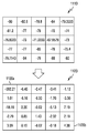
도 14 내지 도 16을 참고하면, 일 실시 예에 따라, 동작 1401에서, 전자 장치(101)(예: 도 1의 프로세서(120))는 전체 NR개의 수신 빔들 중 NS개의 수신 빔들을 선택할 수 있다. 예를 들어, 도 15와 같이, 5개의 수평 각도들(예: -40°, -20°, 0°, +20°, +40°) 및 5개의 수직 각도들(예: -40°, -20°, 0°, +20°, +40°)이 지원되고, 총 25개의 수신 빔들 중 7개의 수신 빔들이 선택될 수 있다. 도 15의 경우, 수평 축에서 3개의 각도들이, 수직 축에서 2개의 각도들이 선택되었으며, 수평 축 및 수직 축 각각에서 등간격으로 각도들이 선택됨으로써, 선택된 각도들 간 거리가 최대일 수 있다. 그 결과, 전체 수신 신호 품질 값들(1510) 중 일부 7개의 수신 신호 품질 값들(1520)만이 측정될 수 있다.14 to 16, according to an embodiment, in operation 1401, the electronic device 101 (eg, the
일 실시 예에 따라, 동작 1403에서, 전자 장치(101)는 비용 함수를 최소화하는 DCT 계수들을 결정할 수 있다. 예를 들어, 전자 장치(101)는 상기 7개 수신 신호 품질 값들에 기반하여 DCT 계수들을 경사하강법으로 추정할 수 있다. 추정되는 계수들의 개수 W가 10인 경우, 도 16의 행렬(1610)과 같이 좌측상단의 원소로부터 10개의 원소들의 값만을 포함하는 기저 변환 행렬(예: DCT 행렬)이 추정될 수 있다.According to an embodiment, in operation 1403, the
일 실시 예에 따라, 동작 1405에서, 전자 장치(101)는 iDCT를 수행함으로써 최적 수신 빔을 예측할 수 있다. 예를 들어, 도 16을 참고하면, 전자 장치(101)는 행렬(1610)에 대한 iDCT를 수행함으로써, 행렬(1620)을 획득할 수 있다. 행렬(1620)의 각 원소의 위치는 각 수신 빔을, 각 원소의 값은 해당 수신 빔에 대한 예측되는 수신 신호 품질을 의미할 수 있다. 도 16의 행렬(1620)을 참고하면, 3행-4열의 값이 -70.9651dBm으로서 최대이므로, 3행-4열에 대응하는 수신 빔이 최적의 수신 빔으로서 예측될 수 있다.According to an embodiment, in operation 1405, the
일 실시 예에 따라, 동작 1407에서, 전자 장치(101)는 예측된 수신 빔으로 수신 신호 품질을 측정할 수 있다. 동작 1405에서 선택된 최적의 수신 빔은 예측에 기반하므로, 결과를 정확하게 확인하기 위해, 전자 장치(101)는 예측된 최적의 수신 빔에 대한 수신 신호 품질을 실제로 측정할 수 있다. 예를 들어, 전자 장치(101)는 예측된 수신 빔을 이용하여 기지국에서 송신되는 동기 신호 또는 기준 신호를 수신하고, 수신 신호 품질을 측정할 수 있다.According to an embodiment, in
일 실시 예에 따라, 동작 1409에서, 전자 장치(101)는 예측된 수신 빔의 수신 신호 품질 및 NS개 수신 빔들의 수신 신호 품질들 중 최대 값을 비교할 수 있다. 예를 들어, 도 15를 참고하면, 예측된 수신 빔의 측정된 수신 신호 품질은 -67.9579dBm이고, NS개 수신 빔들의 수신 신호 품질들 중 최대 값은 -71.3333dBm일 수 있다. According to an embodiment, in
일 실시예에 따라, 예측된 수신 빔의 수신 신호 품질 및 NS개 수신 빔들의 수신 신호 품질들 중 최대 값보다 크면(1409-예), 동작 1411에서, 전자 장치(101)는 예측된 수신 빔을 선택할 수 있다. 예를 들어, 도 15 및 도 16의 예와 같은 경우, -67.9579dBm이 -71.3333dBm보다 크므로, 전자 장치(101)는 예측에 기반하여 선택된 수신 빔을 최적의 수신 빔으로서 결정할 수 있다.According to an embodiment, if the received signal quality of the predicted received beam and the received signal quality of the NS received beams are greater than the maximum value (1409-YES), in operation 1411, the
일 실시 예에 따라, 예측된 수신 빔의 수신 신호 품질이 NS개 수신 빔들의 수신 신호 품질들 중 최대 값보다 작거나 같으면(1409-아니오), 동작 1413에서, 전자 장치(101)는 NS개 수신 빔들 중 최대의 수신 신호 품질을 가지는 수신 빔을 선택할 수 있다. 예를 들어, 도 15 및 도 16의 예와 달리, NS개 수신 빔들의 수신 신호 품질들 중 최대 값이 예측에 기반하여 선택된 수신 빔의 수신 신호 품질보다 크면, 전자 장치(101)는 NS개 수신 빔들 중 최대 수신 신호 품질을 가지는 수신 빔을 최적의 수신 빔으로 결정할 수 있다.According to an embodiment, if the received signal quality of the predicted received beam is less than or equal to a maximum value of received signal quality of the NS received beams (1409-No), in operation 1413, the
도 14를 참고하여 설명한 실시 예에서, 전자 장치는 예측에 기반하여 선택된 수신 빔에 대한 수신 신호 품질을 측정할 수 있다. 만일, 예측에 기반하여 선택된 수신 빔이, 동작 1401에서 선택된 NS개 수신 빔들 중 하나인 경우, 다른 실시 예에 따라, 전자 장치는 동작 1407을 생략하고, 동작 1409을 수행할 수 있다. 예측된 수신 빔이 이미 측정된 수신 빔이므로, 전자 장치는 재측정하는 동작을 생략함으로써, 최적의 빔을 결정하기 위한 시간을 줄일 수 있다. 도 14를 참고하여 설명한 실시 예에서, 전자 장치는 NS개의 수신 빔들을 선택할 수 있다. NS는 고정된 값으로 정의되거나 또는 적응적으로 선택되도록 정의될 수 있다. 일 실시 예에 따라, 이하 도 17과 같이, 관측할 수신 빔의 개수 NS는 상황에 따라 조절될 수 있다. In the embodiment described with reference to FIG. 14, the electronic device may measure the received signal quality for the selected received beam based on the prediction. If the received beam selected based on the prediction is one of the NS received beams selected in operation 1401, according to another embodiment, the electronic device may skip
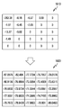
도 17은 다양한 실시 예들에 따른 샘플링된 수신 빔들에 대한 측정 값들의 예들이다. 도 17은 전체 수신 빔들의 수신 신호 품질 값들(1710) 중 9개의 수신 신호 품질 값들(1720a), 8개의 수신 신호 품질 값들(1720b), 7개의 수신 신호 품질 값들(1720c)이 사용되는 경우들을 예시한다.17 is an example of measurement values for sampled receive beams according to various embodiments. FIG. 17 illustrates cases in which 9 received
예를 들어, 예측된 수신 빔이 관측된 NS개 수신 빔보다 좋지 않은 빈도가 높다면(예: 도 14의 동작 1409에서 아니오로 판단되는 빈도가 제1 임계치 이상이면), 전자 장치는 예측의 정확도 향상을 위해 NS를 늘릴 수 있다. 도 17을 참고하면, 8개의 수신 신호 품질 값들(1720b)에 기반하여 예측된 결과가 번복되는 상황이 일정 수준 이상 반복되면, 9개의 수신 신호 품질 값들(1720a)을 사용하도록 NS가 증가할 수 있다.For example, if the predicted receive beam has a higher frequency than the observed NS receive beams (for example, if the frequency determined to be No in
예를 들어, 예측된 수신 빔이 관측된 NS개 수신 빔보다 좋은 빈도가 높다면(예: 도 14의 동작 1409에서 예로 판단되는 빈도가 제2 임계치 이상이면), 전자 장치는 시간 절약을 위해 NS를 줄일 수 있다. 도 17을 참고하면, 8개의 수신 신호 품질 값들(1720b)에 기반하여 예측된 결과가 유지되는 상황이 일정 수준 이상 반복되면, 7개의 수신 신호 품질 값들(1720a)을 사용하도록 NS가 감소할 수 있다.For example, if the predicted reception beam has a higher frequency than the observed NS reception beams (for example, if the frequency determined as YES in
본 발명의 다양한 실시 예들에 따르면, 전자 장치(예: 도 1의 전자 장치(101), 도 2의 기지국(220))의 동작 방법은, 수신 빔들 중 일부를 통해 동기 신호 또는 기준 신호를 수신하는 동작, 상기 수신 빔들 중 일부에 대한 측정 결과에 기반하여 상기 수신 빔들에 대한 수신 신호 품질 값들을 결정하는 동작, 상기 수신 신호 품질 값들에 기반하여 최적의 수신 빔을 결정하는 동작을 포함할 수 있다.According to various embodiments of the present invention, an operation method of an electronic device (for example, the
본 발명의 다양한 실시 예들에 따르면, 상기 수신 신호 품질 값들을 결정하는 동작은, 상기 수신 빔들 간 상관도에 기반하여 상기 수신 신호 품질 값들을 예측하는 동작을 포함할 수 있다.According to various embodiments of the present invention, the operation of determining the received signal quality values may include the operation of predicting the received signal quality values based on the correlation between the received beams.
본 발명의 다양한 실시 예들에 따르면, 상기 수신 빔들 중 일부는, 상기 일부에 속하는 수신 빔들 간 상관도들이 최소화되도록 결정될 수 있다.According to various embodiments of the present invention, some of the received beams may be determined such that correlations between received beams belonging to the part are minimized.
본 발명의 다양한 실시 예들에 따르면, 상기 수신 신호 품질 값들을 결정하는 동작은, 제1 행렬을 결정하는 동작, 상기 제1 행렬을 역-기저 변환함으로써 제2 행렬을 결정하는 동작, 상기 제2 행렬에 포함된 원소들의 값들을 확인하는 동작을 포함할 수 있다.According to various embodiments of the present invention, the operation of determining the received signal quality values includes: determining a first matrix, determining a second matrix by inverse-base transforming the first matrix, and the second matrix It may include the operation of checking the values of the elements included in.
본 발명의 다양한 실시 예들에 따르면, 상기 제1 행렬을 결정하는 동작은,According to various embodiments of the present invention, the determining of the first matrix may include:
상기 제2 행렬에 포함된 원소들 중 상기 수신 빔들 중 일부에 속하는 적어도 하나의 수신 빔의 위치에 대응하는 적어도 하나의 원소의 값 및 상기 수신 빔들 중 일부에 대한 적어도 하나의 수신 신호 품질 값 간 오차를 최소화하도록 상기 제1 행렬을 결정하는 동작을 포함할 수 있다.Error between at least one element value corresponding to the position of at least one received beam belonging to some of the received beams among elements included in the second matrix and at least one received signal quality value for some of the received beams And determining the first matrix to minimize.
본 발명의 다양한 실시 예들에 따르면, 상기 제1 행렬을 결정하는 동작은, 상기 제1 행렬의 원소들 중 일부 원소들의 값들을 추정하는 동작, 나머지 원소들의 값들을 0으로 결정하는 동작을 포함할 수 있다.According to various embodiments of the present invention, the operation of determining the first matrix may include the operation of estimating the values of some of the elements of the first matrix, and the operation of determining the values of the remaining elements as 0. have.
본 발명의 다양한 실시 예들에 따르면, 상기 일부 원소들의 값들을 추정하는 동작은, 좌측 첫번째 및 상단 첫번째의 원소로부터 시작하여 지그재그 순서로 상기 일부 원소들의 값들을 추정하는 동작을 포함할 수 있다.According to various embodiments of the present invention, the operation of estimating the values of some of the elements may include estimating the values of some of the elements in a zigzag order starting from the first left and top first elements.
본 발명의 다양한 실시 예들에 따르면, 상기 일부 원소들의 개수는, 상기 수신 빔들 간 상관도에 기반하여 예측된 수신 신호 품질 값들 중 최대 값에 대응하는 제1 수신 빔에 대하여 측정된 제1 수신 신호 품질 값이, 상기 수신 빔들 중 일부에 대한 측정 결과에 포함된 수신 신호 품질 값들 중 최대 값에 대응하는 제2 수신 빔에 대하여 측정된 제2 수신 신호 품질 값보다 작은 경우의 발생 빈도에 기반하여 조절될 수 있다.According to various embodiments of the present invention, the number of some of the elements is the first received signal quality measured for the first received beam corresponding to the maximum value among the predicted received signal quality values based on the correlation between the received beams The value is adjusted based on the frequency of occurrence when the second received beam quality value measured for the second received beam corresponding to the maximum value among the received signal quality values included in the measurement result for some of the received beams Can be.
본 발명의 다양한 실시 예들에 따르면, 상기 수신 신호 품질 값들에 기반하여 상기 최적의 수신 빔을 결정하는 동작은, 상기 수신 신호 품질 값들 중 최대 값에 대응하는 제1 수신 빔을 이용하여 동기 신호 또는 기준 신호를 수신하는 동작, 상기 동기 신호 또는 상기 기준 신호에 대한 측정을 수행함으로써, 상기 제1 수신 빔에 대한 제1 수신 신호 품질 값을 확인하는 동작, 상기 제1 수신 신호 품질 값에 기반하여 상기 최적의 수신 빔을 결정하는 동작을 포함할 수 있다.According to various embodiments of the present invention, the operation of determining the optimal received beam based on the received signal quality values may include a synchronization signal or a reference using a first received beam corresponding to a maximum value among the received signal quality values. Receiving a signal, determining a first received signal quality value for the first received beam by performing measurement on the synchronization signal or the reference signal, and based on the first received signal quality value It may include the operation of determining the received beam of.
본 발명의 다양한 실시 예들에 따르면, 상기 제1 수신 신호 품질 값에 기반하여 상기 최적의 수신 빔을 결정하는 동작은,According to various embodiments of the present invention, the operation of determining the optimal received beam based on the first received signal quality value may include:
상기 수신 빔들 중 일부에 대한 측정 결과에 포함되는 수신 신호 품질 값들 중 최대 값에 대응하는 제2 수신 빔에 대한 제2 수신 신호 품질 값을 확인하는 동작, 상기 제1 수신 신호 품질 값 보다 상기 제2 수신 신호 품질 값이 크면, 상기 제1 수신 빔을 상기 최적의 수신 빔으로서 선택하는 동작, 상기 제1 수신 신호 품질 값 보다 상기 제2 수신 신호 품질 값이 작거나 같으면, 상기 제2 수신 빔을 상기 최적의 수신 빔으로서 선택하는 동작을 포함할 수 있다.Checking a second received signal quality value for a second received beam corresponding to a maximum value among received signal quality values included in a measurement result of some of the received beams, the second being greater than the first received signal quality value If the received signal quality value is large, the operation of selecting the first received beam as the optimal received beam, if the second received signal quality value is less than or equal to the first received signal quality value, the second received beam is And selecting the optimal reception beam.
도 18은 다양한 실시 예들에 따른 최적의 빔 결정 동작들을 위한 논리적 구조의 블록도이다. 도 18에 예시된 모듈들 중 적어도 일부는 프로세서(예: 도 1의 프로세서(120))에 상주된(resided) 명령어/코드이거나, 또는, 프로세서를 구성하는 회로(circuitry)의 일부로 이해될 수 있다.18 is a block diagram of a logical structure for optimal beam determination operations according to various embodiments. At least some of the modules illustrated in FIG. 18 may be instructions/code residing on a processor (eg,
도 18을 참고하면, 빔 선택 모듈(1810)에서 빔 선택 동작 및 측정 동작(예: 도 14의 동작 1401)이 수행되며, NS 개의 RSRP 값들이 출력될 수 있다. NS 개의 RSRP 값들은 DCT 계수 추정 모듈(1820)로 입력되고, DCT 계수 추정 모듈(1820)에서 DCT 행렬의 W개의 원소 값들의 추정 동작(예: 도 14의 동작 1403)이 수행될 수 있다. W개의 계수 값들은 빔 선택 모듈(1830)로 입력되고, 빔 선택 모듈(1830)에서 iDCT 연산을 이용하는 예측에 기반한 수신 빔 선택 동작(예: 도 14의 동작 1405)이 수행될 수 있다. 예측에 기반하여 선택된 수신 빔의 인덱스는 RSRP 측정 모듈(1840)로 입력되고, RSRP 측정 모듈(1840)에서 예측에 기반하여 선택된 수신 빔에 대한 RSRP 측정 동작(예: 도 14의 동작 1407)이 수행될 수 있다. 예측에 기반하여 선택된 수신 빔에 대한 RSRP 값은 최적의 빔 판단 모듈(1850)에 입력되고, 최적의 빔 판단 모듈(1850)에서 빔 선택 모듈(1810)에 의해 측정된 RSRP 값 및 RSRP 측정 모듈(1840)에 의해 측정된 RSRP 값의 비교 동작 및 최적의 빔 결정 동작(예: 도 14의 동작 1409, 동작 1411, 동작 1413)이 수행된 후, 최적의 빔의 인덱스가 출력될 수 있다.Referring to FIG. 18, a beam selection operation and a measurement operation (eg, operation 1401 of FIG. 14) are performed by the
상술 및 후술할 다양한 실시 예들은 RSRP라는 대표적인 수신 신호 품질 값을 통해 설명되었다. 다양한 실시 예들은 SNR(signal to noise ratio), SINR(signal to interference and noise ratio), CINR(carrier to interference and noise ratio), RSRQ(reference signal received quality) 및/또는 RSSI(received signal strength indicator)와 같은 신호의 품질을 나타내는 다른 파라미터 값, 혹은 다른 RS(reference signal)에 관련된 값을 이용하여 실시될 수 있다.Various embodiments described above and below have been described through a representative received signal quality value called RSRP. Various embodiments include signal to noise ratio (SNR), signal to interference and noise ratio (SINR), carrier to interference and noise ratio (CINR), reference signal received quality (RSRQ) and/or received signal strength indicator (RSSI), and It may be implemented using different parameter values representing the same signal quality or values related to different RS (reference signal).
상술한 다양한 실시 예들은 전자 장치의 안테나가 2차원 어레이의 형태인 경우를 전제로 설명되었다. 그러나, 상술한 다양한 실시 예들은 다른 환경에서도 유사하게 적용될 수 있다.The various embodiments described above have been described on the assumption that the antenna of the electronic device is in the form of a two-dimensional array. However, the various embodiments described above can be similarly applied in other environments.
예를 들어. 하나의 1차원 어레이 안테나를 사용하는 경우, 복수의 1차원 어레이 안테나들을 사용하는 경우, 또는 복수의 2차원 어레이 안테나들을 사용하는 경우에도, 상술한 실시 예들이 적용될 수 있다. 복수의 1차원 혹은 2차원 어레이 안테나들을 사용하는 경우, 어레이 안테나들이 전자 장치의 상측, 하측, 좌측 및/또는 우측에 배치되어 충분한 상관관계를 가지면, 상술한 실시 예들이 적용될 수 있다. 복수의 2차원 어레이 안테나들을 사용하는 경우, 안테나 어레이들에서 형성되는 빔들이 보어사이트(boresight)가 동일 방향을 향하여 충분한 상관관계를 가지면, 상술한 실시 예들이 적용될 수 있다.For example. In the case of using a single one-dimensional array antenna, a plurality of one-dimensional array antennas, or a plurality of two-dimensional array antennas, the above-described embodiments may be applied. When a plurality of one-dimensional or two-dimensional array antennas are used, if the array antennas are disposed on the upper, lower, left and/or right side of the electronic device and have a sufficient correlation, the above-described embodiments may be applied. When using a plurality of two-dimensional array antennas, if the beams formed in the antenna arrays have a sufficient correlation in which the boresight is directed in the same direction, the above-described embodiments can be applied.
예를 들어, 서로 다른 종류의 어레이 안테나들이 혼용되는 경우에도, 상술한 실시 예들이 적용될 수 있다. 1차원 어레이 패치(patch) 안테나 및 1차원 다이폴(dipole) 안테나가 사용되고, 각 안테나에서 형성되는 빔이 수평 또는 수직 방향에서 스티어링(steering)되는 경우, 상술한 실시 예들이 적용될 수 있다. 2차원 어레이 패치 안테나 및 1차원 어레이 다이폴 안테나가 사용되고, 각 안테나에서 형성되는 빔이 수평 또는 수직 방향에서 스티어링되는 경우, 상술한 실시 예들이 적용될 수 있다. For example, even when different types of array antennas are mixed, the above-described embodiments may be applied. When a one-dimensional array patch antenna and a one-dimensional dipole antenna are used, and the beam formed in each antenna is steered in a horizontal or vertical direction, the above-described embodiments may be applied. When a two-dimensional array patch antenna and a one-dimensional array dipole antenna are used, and the beam formed from each antenna is steered in the horizontal or vertical direction, the above-described embodiments may be applied.
도 19 및 도 20은 다양한 실시 예들에 따른 최적의 빔 선택 기법의 성능 그래프들이다. 도 19 및 도 20에서. 예측된 수신 빔에 대한 RSRP 및 실제 최적의 수신 빔에 대한 RSRP의 차이는 RMS(root-mean-square) 오차(error)로 표현될 수 있다. RSRP 분포는 결합 가우시안(joint Gaussian) 분포에 따르며, 'K-best' 알고리즘은 단순히 NS개의 수신 빔들의 RSRP들 중 최대값을 가지는 수신 빔을 선택하는 기법으로서, 성능의 하한에 해당할 수 있다. 도 19는 수평 방향으로 5개 각도들, 수직 방향으로 5개 각도들이 지원되는 경우를, 도 19은 수평 방향으로 5개 각도들, 수직 방향으로 1개 각도가 지원되는 경우의 실험 결과일 수 있다. 도 19 및 도 20을 참고하면, 1차원, 2차원 빔 모두 적절한 개수의 DCT 계수들을 선택함으로써 K-best 알고리즘보다 우수한 성능이 확보됨이 확인될 수 있다.19 and 20 are performance graphs of an optimal beam selection technique according to various embodiments. In Figures 19 and 20. The difference between RSRP for the predicted receive beam and RSRP for the actual optimal receive beam may be expressed as a root-mean-square (RMS) error. The RSRP distribution is based on a joint Gaussian distribution, and the'K-best' algorithm is simply a method of selecting a reception beam having a maximum value among RSRPs of NS reception beams, which may correspond to a lower limit of performance. 19 may be an experiment result when 5 angles are supported in the horizontal direction and 5 angles are supported in the horizontal direction, and FIG. 19 is 5 angles in the horizontal direction and 1 angle is supported in the vertical direction. . Referring to FIGS. 19 and 20, it can be confirmed that performance is superior to the K-best algorithm by selecting an appropriate number of DCT coefficients for both the 1D and 2D beams.
본 문서에 개시된 다양한 실시 예들에 따른 전자 장치는 다양한 형태의 장치가 될 수 있다. 전자 장치는, 예를 들면, 휴대용 통신 장치(예: 스마트폰), 컴퓨터 장치, 휴대용 멀티미디어 장치, 휴대용 의료 장치, 카메라, 웨어러블 장치, 또는 가전 장치를 포함할 수 있다. 본 문서의 실시 예에 따른 전자 장치는 전술한 장치들에 한정되지 않는다.An electronic device according to various embodiments disclosed in the present disclosure may be various types of devices. The electronic device may include, for example, a portable communication device (eg, a smart phone), a computer device, a portable multimedia device, a portable medical device, a camera, a wearable device, or a home appliance device. The electronic device according to the exemplary embodiment of the present document is not limited to the aforementioned devices.
본 문서의 다양한 실시 예들 및 이에 사용된 용어들은 본 문서에 기재된 기술적 특징들을 특정한 실시 예들로 한정하려는 것이 아니며, 해당 실시 예의 다양한 변경, 균등물, 또는 대체물을 포함하는 것으로 이해되어야 한다. 도면의 설명과 관련하여, 유사한 또는 관련된 구성요소에 대해서는 유사한 참조 부호가 사용될 수 있다. 아이템에 대응하는 명사의 단수 형은 관련된 문맥상 명백하게 다르게 지시하지 않는 한, 아이템 한 개 또는 복수 개를 포함할 수 있다. 본 문서에서, "A 또는 B", "A 및 B 중 적어도 하나","A 또는 B 중 적어도 하나,""A, B 또는 C," "A, B 및 C 중 적어도 하나,"및 "A, B, 또는 C 중 적어도 하나"와 같은 문구들 각각은 그 문구들 중 해당하는 문구에 함께 나열된 항목들 중 어느 하나, 또는 그들의 모든 가능한 조합을 포함할 수 있다. "제1", "제2", 또는 "첫째" 또는 "둘째"와 같은 용어들은 단순히 해당 구성요소를 다른 해당 구성요소와 구분하기 위해 사용될 수 있으며, 해당 구성요소들을 다른 측면(예: 중요성 또는 순서)에서 한정하지 않는다. 어떤(예: 제1) 구성요소가 다른(예: 제2) 구성요소에, "기능적으로" 또는 "통신적으로"라는 용어와 함께 또는 이런 용어 없이, "커플드" 또는 "커넥티드"라고 언급된 경우, 그것은 어떤 구성요소가 다른 구성요소에 직접적으로(예: 유선으로), 무선으로, 또는 제3 구성요소를 통하여 연결될 수 있다는 것을 의미한다.It should be understood that various embodiments of the document and terms used therein are not intended to limit the technical features described in this document to specific embodiments, and include various modifications, equivalents, or substitutes of the corresponding embodiments. In connection with the description of the drawings, similar reference numerals may be used for similar or related components. The singular form of a noun corresponding to an item may include one item or plural items, unless the context clearly indicates otherwise. In this document, "A or B", "at least one of A and B", "at least one of A or B," "A, B or C," "at least one of A, B and C," and "A Each of the phrases such as "at least one of,, B, or C" may include any one of the items listed together in the corresponding phrase of the phrases, or all possible combinations thereof. Terms such as “first”, “second”, or “first” or “second” can be used to simply distinguish a component from other components, and to separate components from other aspects (eg, importance or Order). Any (eg, first) component is referred to as “coupled” or “connected” to another (eg, second) component, with or without the term “functionally” or “communically” When mentioned, it means that one component can be connected directly to another component (eg, by wire), wirelessly, or through a third component.
본 문서에서 사용된 용어 "모듈"은 하드웨어, 소프트웨어 또는 펌웨어로 구현된 유닛을 포함할 수 있으며, 예를 들면, 로직, 논리 블록, 부품, 또는 회로 등의 용어와 상호 호환적으로 사용될 수 있다. 모듈은, 일체로 구성된 부품 또는 하나 또는 그 이상의 기능을 수행하는, 부품의 최소 단위 또는 그 일부가 될 수 있다. 예를 들면, 일 실시 예에 따르면, 모듈은 ASIC(application-specific integrated circuit)의 형태로 구현될 수 있다. As used herein, the term "module" may include units implemented in hardware, software, or firmware, and may be used interchangeably with terms such as, for example, logic, logic blocks, components, or circuits. The module may be an integrally configured component or a minimum unit of components or a part thereof performing one or more functions. For example, according to an embodiment, the module may be implemented in the form of an application-specific integrated circuit (ASIC).
본 문서의 다양한 실시 예들은 장치(machine)(예: 전자 장치(101)) 의해 읽을 수 있는 저장 매체(storage medium)(예: 내장 메모리(136) 또는 외장 메모리(138))에 저장된 하나 이상의 명령어들을 포함하는 소프트웨어(예: 프로그램(140))로서 구현될 수 있다. 예를 들면, 장치(예: 전자 장치(101))의 프로세서(예: 프로세서(120))는, 저장 매체로부터 저장된 하나 이상의 명령어들 중 적어도 하나의 명령을 호출하고, 그것을 실행할 수 있다. 이것은 장치가 호출된 적어도 하나의 명령어에 따라 적어도 하나의 기능을 수행하도록 운영되는 것을 가능하게 한다. 하나 이상의 명령어들은 컴파일러에 의해 생성된 코드 또는 인터프리터에 의해 실행될 수 있는 코드를 포함할 수 있다. 장치로 읽을 수 있는 저장매체 는, 비일시적(non-transitory) 저장매체의 형태로 제공될 수 있다. 여기서, '비일시적'은 저장매체가 실재(tangible)하는 장치이고, 신호(signal)(예: EM파)를 포함하지 않는다는 것을 의미할 뿐이며, 이 용어는 데이터가 저장매체에 반영구적으로 저장되는 경우와 임시적으로 저장되는 경우를 구분하지 않는다.Various embodiments of the present disclosure may include one or more instructions stored in a storage medium (eg, internal memory 136 or external memory 138) readable by a machine (eg, electronic device 101). It may be implemented as software (e.g., program 140) that includes. For example, a processor (eg, processor 120) of a device (eg, electronic device 101) may call and execute at least one of one or more commands stored from a storage medium. This enables the device to be operated to perform at least one function according to at least one command called. The one or more instructions may include code generated by a compiler or code that can be executed by an interpreter. The device-readable storage medium may be provided in the form of a non-transitory storage medium. Here,'non-transitory' means that the storage medium is a tangible device and does not include a signal (eg, EM wave), and this term is used when data is stored semi-permanently on the storage medium. And the case of temporary storage.
일 실시 예에 따르면, 본 문서에 개시된 다양한 실시 예들에 따른 방법은 컴퓨터 프로그램 제품(computer program product)에 포함되어 제공될 수 있다. 컴퓨터 프로그램 제품은 상품으로서 판매자 및 구매자 간에 거래될 수 있다. 컴퓨터 프로그램 제품은 장치로 읽을 수 있는 저장 매체(예: CD-ROM(compact disc read only memory))의 형태로 배포되거나, 또는 어플리케이션 스토어(예: 플레이 스토어TM)를 통해 또는 두개의 사용자 장치들(예: 스마트폰들) 간에 직접, 온라인으로 배포(예: 다운로드 또는 업로드)될 수 있다. 온라인 배포의 경우에, 컴퓨터 프로그램 제품의 적어도 일부는 제조사의 서버, 어플리케이션 스토어의 서버, 또는 중계 서버의 메모리와 같은 장치로 읽을 수 있는 저장 매체에 적어도 일시 저장되거나, 임시적으로 생성될 수 있다.According to an embodiment, a method according to various embodiments disclosed in this document may be provided as being included in a computer program product. Computer program products can be traded between sellers and buyers as products. The computer program product may be distributed in the form of a device-readable storage medium (eg compact disc read only memory (CD-ROM)), or through an application store (eg Play Store TM ) or two user devices ( For example, it can be distributed directly (e.g., downloaded or uploaded) between smartphones). In the case of online distribution, at least a portion of the computer program product may be stored at least temporarily in a storage medium readable by a device such as a memory of a manufacturer's server, an application store's server, or a relay server, or may be temporarily generated.
다양한 실시 예들에 따르면, 기술한 구성요소들의 각각의 구성요소(예: 모듈 또는 프로그램)는 단수 또는 복수의 개체를 포함할 수 있다. 다양한 실시 예들에 따르면, 전술한 해당 구성요소들 중 하나 이상의 구성요소들 또는 동작들이 생략되거나, 또는 하나 이상의 다른 구성요소들 또는 동작들이 추가될 수 있다. 대체적으로 또는 추가적으로, 복수의 구성요소들(예: 모듈 또는 프로그램)은 하나의 구성요소로 통합될 수 있다. 이런 경우, 통합된 구성요소는 복수의 구성요소들 각각의 구성요소의 하나 이상의 기능들을 통합 이전에 복수의 구성요소들 중 해당 구성요소에 의해 수행되는 것과 동일 또는 유사하게 수행할 수 있다. 다양한 실시 예들에 따르면, 모듈, 프로그램 또는 다른 구성요소에 의해 수행되는 동작들은 순차적으로, 병렬적으로, 반복적으로, 또는 휴리스틱하게 실행되거나, 동작들 중 하나 이상이 다른 순서로 실행되거나, 생략되거나, 또는 하나 이상의 다른 동작들이 추가될 수 있다.According to various embodiments, each component (eg, module or program) of the described components may include a singular or a plurality of entities. According to various embodiments, one or more components or operations of the above-described corresponding components may be omitted, or one or more other components or operations may be added. Alternatively or additionally, a plurality of components (eg, modules or programs) may be integrated into one component. In this case, the integrated component may perform one or more functions of each component of the plurality of components the same or similar to that performed by the corresponding component among the plurality of components prior to integration. According to various embodiments, operations performed by a module, program, or other component may be executed sequentially, in parallel, repeatedly, or heuristically, or one or more of the operations may be executed in a different order, omitted, or the like. Or one or more other actions can be added.
Claims (20)
수신 빔들 중 일부를 통해 동기 신호 또는 기준 신호를 수신하는 동작;
상기 수신 빔들 중 일부에 대한 측정 결과에 기반하여 상기 수신 빔들에 대한 수신 신호 품질 값들을 결정하는 동작; 및
상기 수신 신호 품질 값들에 기반하여 최적의 수신 빔을 결정하는 동작을 포함하는 방법.
In the operation method of the electronic device,
Receiving a synchronization signal or a reference signal through some of the reception beams;
Determining received signal quality values for the received beams based on a measurement result of some of the received beams; And
And determining an optimal receive beam based on the received signal quality values.
상기 수신 신호 품질 값들을 결정하는 동작은,
상기 수신 빔들 간 상관도에 기반하여 상기 수신 신호 품질 값들을 예측하는 동작을 포함하는 방법.
According to claim 1,
Determining the received signal quality values,
And predicting the received signal quality values based on the correlation between the received beams.
상기 수신 빔들 중 일부는, 상기 일부에 속하는 수신 빔들 간 상관도들이 최소화되도록 결정되는 방법.
According to claim 1,
A method in which some of the received beams are determined such that correlations between received beams belonging to the portion are minimized.
상기 수신 신호 품질 값들을 결정하는 동작은,
제1 행렬을 결정하는 동작;
상기 제1 행렬을 역-기저 변환함으로써 제2 행렬을 결정하는 동작; 및
상기 제2 행렬에 포함된 원소들의 값들을 확인하는 동작을 포함하는 방법.
According to claim 1,
Determining the received signal quality values,
Determining a first matrix;
Determining a second matrix by inverse-base transforming the first matrix; And
And checking values of elements included in the second matrix.
상기 제1 행렬을 결정하는 동작은,
상기 제2 행렬에 포함된 원소들 중 상기 수신 빔들 중 일부에 속하는 적어도 하나의 수신 빔의 위치에 대응하는 적어도 하나의 원소의 값 및 상기 수신 빔들 중 일부에 대한 적어도 하나의 수신 신호 품질 값 간 오차를 최소화되도록 상기 제1 행렬을 결정하는 동작을 포함하는 방법.
According to claim 4,
Determining the first matrix,
Error between at least one element value corresponding to the position of at least one received beam belonging to some of the received beams among elements included in the second matrix and at least one received signal quality value for some of the received beams And determining the first matrix to be minimized.
상기 제1 행렬을 결정하는 동작은,
상기 제1 행렬의 원소들 중 일부 원소들의 값들을 추정하는 동작; 및
나머지 원소들의 값들을 0으로 결정하는 동작을 포함하는 방법.
According to claim 4,
Determining the first matrix,
Estimating values of some of the elements of the first matrix; And
And including determining the values of the remaining elements as zero.
상기 일부 원소들의 값들을 추정하는 동작은,
좌측 첫번째 및 상단 첫번째의 원소로부터 시작하여 지그재그 순서로 상기 일부 원소들의 값들을 추정하는 동작을 포함하는 방법.
The method of claim 6,
Estimating the values of some of the elements,
And estimating the values of some of the elements in a zigzag order starting from the first left and top first elements.
상기 일부 원소들의 개수는,
상기 수신 빔들 간 상관도에 기반하여 예측된 수신 신호 품질 값들 중 최대 값에 대응하는 제1 수신 빔에 대하여 측정된 제1 수신 신호 품질 값이, 상기 수신 빔들 중 일부에 대한 측정 결과에 포함된 수신 신호 품질 값들 중 최대 값에 대응하는 제2 수신 빔에 대하여 측정된 제2 수신 신호 품질 값보다 작은 경우의 발생 빈도에 기반하여 조절되는 방법.
The method of claim 6,
The number of some of the elements,
The first received signal quality value measured for the first received beam corresponding to the maximum value among the predicted received signal quality values based on the correlation between the received beams is included in the measurement result for some of the received beams A method of adjusting based on the frequency of occurrence when the second received beam quality value of the second received beam corresponding to the maximum value among the signal quality values is smaller than the measured value.
상기 수신 신호 품질 값들에 기반하여 상기 최적의 수신 빔을 결정하는 동작은,
상기 수신 신호 품질 값들 중 최대 값에 대응하는 제1 수신 빔을 이용하여 동기 신호 또는 기준 신호를 수신하는 동작;
상기 동기 신호 또는 상기 기준 신호에 대한 측정을 수행함으로써, 상기 제1 수신 빔에 대한 제1 수신 신호 품질 값을 확인하는 동작; 및
상기 제1 수신 신호 품질 값에 기반하여 상기 최적의 수신 빔을 결정하는 동작을 포함하는 방법.
According to claim 1,
Determining the optimal received beam based on the received signal quality values,
Receiving a synchronization signal or a reference signal using a first received beam corresponding to a maximum value among the received signal quality values;
Determining a first received signal quality value for the first received beam by performing measurement on the synchronization signal or the reference signal; And
And determining the optimal receive beam based on the first received signal quality value.
상기 제1 수신 신호 품질 값에 기반하여 상기 최적의 수신 빔을 결정하는 동작은,
상기 수신 빔들 중 일부에 대한 측정 결과에 포함되는 수신 신호 품질 값들 중 최대 값에 대응하는 제2 수신 빔에 대한 제2 수신 신호 품질 값을 확인하는 동작;
상기 제1 수신 신호 품질 값 보다 상기 제2 수신 신호 품질 값이 크면, 상기 제1 수신 빔을 상기 최적의 수신 빔으로서 선택하는 동작; 및
상기 제1 수신 신호 품질 값 보다 상기 제2 수신 신호 품질 값이 작거나 같으면, 상기 제2 수신 빔을 상기 최적의 수신 빔으로서 선택하는 동작을 포함하는 방법.
The method of claim 9,
Determining the optimal received beam based on the first received signal quality value,
Checking a second received signal quality value for a second received beam corresponding to a maximum value among received signal quality values included in a measurement result of some of the received beams;
If the second received signal quality value is greater than the first received signal quality value, selecting the first received beam as the optimal received beam; And
And if the second received signal quality value is less than or equal to the first received signal quality value, selecting the second received beam as the optimal received beam.
메모리;
상기 메모리와 동작적으로 연결된 프로세서를 포함하며,
상기 프로세서는,
수신 빔들 중 일부를 통해 동기 신호 또는 기준 신호를 수신하고;
상기 수신 빔들 중 일부에 대한 측정 결과에 기반하여 상기 수신 빔들에 대한 수신 신호 품질 값들을 결정하고;
상기 수신 신호 품질 값들에 기반하여 최적의 수신 빔을 결정하는 전자 장치.
In the electronic device,
Memory;
It includes a processor operatively connected to the memory,
The processor,
Receive a synchronization signal or a reference signal through some of the received beams;
Determine received signal quality values for the received beams based on a measurement result of some of the received beams;
An electronic device that determines an optimal receive beam based on the received signal quality values.
상기 프로세서는, 상기 수신 빔들 간 상관도에 기반하여 상기 수신 신호 품질 값들을 예측하는 전자 장치.
The method of claim 11,
The processor is an electronic device that predicts the received signal quality values based on the correlation between the received beams.
상기 수신 빔들 중 일부는, 상기 일부에 속하는 수신 빔들 간 상관도들이 최소화되도록 결정되는 전자 장치.
The method of claim 11,
An electronic device in which some of the received beams are determined such that correlations between received beams belonging to the part are minimized.
상기 프로세서는,
제1 행렬을 결정하고;
상기 제1 행렬을 역-기저 변환함으로써 제2 행렬을 결정하고;
상기 제2 행렬에 포함된 원소들의 값들을 확인하는 전자 장치.
The method of claim 11,
The processor,
Determine a first matrix;
Determine a second matrix by inverse-base transforming the first matrix;
An electronic device that checks values of elements included in the second matrix.
상기 프로세서는, 상기 제2 행렬에 포함된 원소들 중 상기 수신 빔들 중 일부에 속하는 적어도 하나의 수신 빔의 위치에 대응하는 적어도 하나의 원소의 값 및 상기 수신 빔들 중 일부에 대한 적어도 하나의 수신 신호 품질 값 간 오차를 최소화되도록 상기 제1 행렬을 결정하는 전자 장치.
The method of claim 14,
The processor may include at least one element value corresponding to a position of at least one received beam belonging to some of the received beams among elements included in the second matrix, and at least one received signal for some of the received beams An electronic device that determines the first matrix to minimize errors between quality values.
상기 프로세서는,
상기 제1 행렬의 원소들 중 일부 원소들의 값들을 추정하고;
나머지 원소들의 값들을 0으로 결정하는 전자 장치.
The method of claim 14,
The processor,
Estimate values of some of the elements of the first matrix;
An electronic device that determines the values of the remaining elements as zero.
상기 프로세서는, 좌측 첫번째 및 상단 첫번째의 원소로부터 시작하여 지그재그 순서로 상기 일부 원소들의 값들을 추정하는 전자 장치.
The method of claim 16,
The processor is an electronic device that estimates the values of the some elements in a zigzag order starting from the first left and top first elements.
상기 일부 원소들의 개수는, 상기 수신 빔들 간 상관도에 기반하여 예측된 수신 신호 품질 값들 중 최대 값에 대응하는 제1 수신 빔에 대하여 측정된 제1 수신 신호 품질 값이, 상기 수신 빔들 중 일부에 대한 측정 결과에 포함된 수신 신호 품질 값들 중 최대 값에 대응하는 제2 수신 빔에 대하여 측정된 제2 수신 신호 품질 값보다 작은 경우의 발생 빈도에 기반하여 조절되는 전자 장치.
The method of claim 16,
The number of some of the elements may include a first received signal quality value measured for a first received beam corresponding to a maximum value among the predicted received signal quality values based on the correlation between the received beams. An electronic device that is adjusted based on the frequency of occurrence when the second received beam corresponding to the maximum value among the received signal quality values included in the measurement result is smaller than the measured second received signal quality value.
상기 프로세서는,
상기 수신 신호 품질 값들 중 최대 값에 대응하는 제1 수신 빔을 이용하여 동기 신호 또는 기준 신호를 수신하고;
상기 동기 신호 또는 상기 기준 신호에 대한 측정을 수행함으로써, 상기 제1 수신 빔에 대한 제1 수신 신호 품질 값을 확인하고;
상기 제1 수신 신호 품질 값에 기반하여 상기 최적의 수신 빔을 결정하는 전자 장치.
The method of claim 11,
The processor,
A synchronization signal or a reference signal is received using a first reception beam corresponding to a maximum value among the received signal quality values;
Confirming a first received signal quality value for the first received beam by performing measurement on the synchronization signal or the reference signal;
An electronic device that determines the optimal receive beam based on the first received signal quality value.
상기 프로세서는,
상기 수신 빔들 중 일부에 대한 측정 결과에 포함되는 수신 신호 품질 값들 중 최대 값에 대응하는 제2 수신 빔에 대한 제2 수신 신호 품질 값을 확인하고;
상기 제1 수신 신호 품질 값 보다 상기 제2 수신 신호 품질 값이 크면, 상기 제1 수신 빔을 상기 최적의 수신 빔으로서 선택하고;
상기 제1 수신 신호 품질 값 보다 상기 제2 수신 신호 품질 값이 작거나 같으면, 상기 제2 수신 빔을 상기 최적의 수신 빔으로서 선택하는 전자 장치.The method of claim 19,
The processor,
Checking a second received signal quality value for a second received beam corresponding to a maximum value among received signal quality values included in a measurement result of some of the received beams;
If the second received signal quality value is greater than the first received signal quality value, select the first received beam as the optimal received beam;
If the second received signal quality value is less than or equal to the first received signal quality value, the electronic device selects the second received beam as the optimal received beam.
Priority Applications (3)
| Application Number | Priority Date | Filing Date | Title |
|---|---|---|---|
| KR1020180170763A KR20200080849A (en) | 2018-12-27 | 2018-12-27 | Method for determinig optimal beam and an electronic device thereof |
| PCT/KR2019/018309 WO2020138888A1 (en) | 2018-12-27 | 2019-12-23 | Method for determining optimal beam and an electronic device thereof |
| US16/728,165 US11424813B2 (en) | 2018-12-27 | 2019-12-27 | Method for determining optimal beam and an electronic device thereof |
Applications Claiming Priority (1)
| Application Number | Priority Date | Filing Date | Title |
|---|---|---|---|
| KR1020180170763A KR20200080849A (en) | 2018-12-27 | 2018-12-27 | Method for determinig optimal beam and an electronic device thereof |
Publications (1)
| Publication Number | Publication Date |
|---|---|
| KR20200080849A true KR20200080849A (en) | 2020-07-07 |
Family
ID=71123401
Family Applications (1)
| Application Number | Title | Priority Date | Filing Date |
|---|---|---|---|
| KR1020180170763A KR20200080849A (en) | 2018-12-27 | 2018-12-27 | Method for determinig optimal beam and an electronic device thereof |
Country Status (3)
| Country | Link |
|---|---|
| US (1) | US11424813B2 (en) |
| KR (1) | KR20200080849A (en) |
| WO (1) | WO2020138888A1 (en) |
Families Citing this family (4)
| Publication number | Priority date | Publication date | Assignee | Title |
|---|---|---|---|---|
| CN110753388B (en) * | 2018-07-23 | 2021-08-20 | 华为技术有限公司 | Beam management method and related equipment |
| WO2022015031A1 (en) * | 2020-07-13 | 2022-01-20 | Samsung Electronics Co., Ltd. | Method and apparatus for selecting beam pairs in a beamforming based communication system |
| US11522620B2 (en) * | 2021-01-27 | 2022-12-06 | Nanning Fulian Fugui Precision Industrial Co., Ltd. | Method for adjusting antenna and communication device using same |
| US20230053589A1 (en) * | 2021-08-17 | 2023-02-23 | Qualcomm Incorporated | Quality metric signaling for beam strength prediction |
Family Cites Families (10)
| Publication number | Priority date | Publication date | Assignee | Title |
|---|---|---|---|---|
| JP5488016B2 (en) * | 2009-03-30 | 2014-05-14 | 富士通株式会社 | Wireless communication method, wireless communication system, and wireless communication apparatus |
| US20120045024A1 (en) * | 2010-02-24 | 2012-02-23 | Qualcomm Incorporated | Methods and apparatus for iterative decoding in multiple-input-multiple-output (mimo) communication systems |
| JP2015185953A (en) | 2014-03-20 | 2015-10-22 | 株式会社Nttドコモ | Beam selection method, base station, and user device |
| KR102318220B1 (en) | 2015-07-01 | 2021-10-27 | 삼성전자주식회사 | Beam selection apparatus and method in a wireless communication system |
| US10630410B2 (en) * | 2016-05-13 | 2020-04-21 | Telefonaktiebolaget Lm Ericsson (Publ) | Network architecture, methods, and devices for a wireless communications network |
| JP2019528022A (en) | 2016-08-11 | 2019-10-03 | ドコモ イノヴェーションズ インクDocomo Innovations, Inc. | Method for selecting reception resource and CSI-RS transmission method |
| KR20180087563A (en) * | 2017-01-25 | 2018-08-02 | 엘지전자 주식회사 | Method and apparatus for configuring optimal beam in hybrid beamforming system |
| CN108696889B (en) * | 2017-03-30 | 2021-09-10 | 财团法人工业技术研究院 | Method for beam measurement and feedback, and base station and user equipment using same |
| EP3471296A4 (en) * | 2017-06-16 | 2020-03-25 | LG Electronics Inc. -1- | Method for measuring synchronization signal block and apparatus therefor |
| US10277349B1 (en) * | 2018-04-30 | 2019-04-30 | Nxp Usa, Inc. | Method and apparatus for fast and robust cell search for 5G and millimeter-wave wireless communication systems |
-
2018
- 2018-12-27 KR KR1020180170763A patent/KR20200080849A/en not_active Application Discontinuation
-
2019
- 2019-12-23 WO PCT/KR2019/018309 patent/WO2020138888A1/en active Application Filing
- 2019-12-27 US US16/728,165 patent/US11424813B2/en active Active
Also Published As
| Publication number | Publication date |
|---|---|
| US20200212991A1 (en) | 2020-07-02 |
| US11424813B2 (en) | 2022-08-23 |
| WO2020138888A1 (en) | 2020-07-02 |
Similar Documents
| Publication | Publication Date | Title |
|---|---|---|
| CN111480303B (en) | Beam steering control device and method based on mobile sensor | |
| US11290166B2 (en) | Electronic device for controlling beam based on data obtained by camera and method for the same | |
| KR102518402B1 (en) | Method for beam selection for communication and electronic device thereof | |
| KR20200080849A (en) | Method for determinig optimal beam and an electronic device thereof | |
| CN112640328B (en) | Method and electronic device for forming beam in wireless communication system | |
| KR102154326B1 (en) | Method and apparatus for beamforming in wireless communication system | |
| US11888236B2 (en) | Method and device for selecting reception beam on basis of artificial neural network | |
| US20200137740A1 (en) | Method and device for performing beam searching in mobile communication system | |
| US11018440B2 (en) | Apparatus and method for determining beam index of antenna array | |
| US11502739B2 (en) | Method for selecting beam and electronic device thereof | |
| US11924787B2 (en) | Electronic device for performing beamforming-based communication, and method therefor | |
| US11943023B2 (en) | Method for controlling plurality of antenna modules, and electronic device therefor | |
| US11581936B2 (en) | Method and apparatus for beam management in antenna array sharing radar and communication systems | |
| KR102530503B1 (en) | Method for generating beam book and an electronic device thereof | |
| KR20210029046A (en) | Method for measuring a beam in electronic device and electronic device | |
| US11736178B2 (en) | Electronic device for selecting antenna module and/or beam and operating method thereof | |
| KR102563984B1 (en) | Method for forming a beam in electronic device and electronic device | |
| US20230319592A1 (en) | Device and method for controlling antenna in wireless communication system | |
| KR20220138223A (en) | Electronic device for selecting antenna module and/or beam and operating mehtod thereof | |
| KR20220064649A (en) | Method for setting a reception beam in electronic device and electronic device | |
| KR20230085683A (en) | Electronic device for channel estimation based on fading channel and operating method thereof | |
| KR20240048440A (en) | Electronic device and operation method of electronic device determining operation mode of uwb module | |
| CN117368841A (en) | Arrival angle AOA acquisition method and electronic equipment |
Legal Events
| Date | Code | Title | Description |
|---|---|---|---|
| A201 | Request for examination | ||
| E902 | Notification of reason for refusal |