JP5487678B2 - Actuator - Google Patents
Actuator Download PDFInfo
- Publication number
- JP5487678B2 JP5487678B2 JP2009084104A JP2009084104A JP5487678B2 JP 5487678 B2 JP5487678 B2 JP 5487678B2 JP 2009084104 A JP2009084104 A JP 2009084104A JP 2009084104 A JP2009084104 A JP 2009084104A JP 5487678 B2 JP5487678 B2 JP 5487678B2
- Authority
- JP
- Japan
- Prior art keywords
- carbon powder
- actuator
- ion conductive
- conductive polymer
- layer
- Prior art date
- Legal status (The legal status is an assumption and is not a legal conclusion. Google has not performed a legal analysis and makes no representation as to the accuracy of the status listed.)
- Active
Links
- OKTJSMMVPCPJKN-UHFFFAOYSA-N Carbon Chemical compound [C] OKTJSMMVPCPJKN-UHFFFAOYSA-N 0.000 claims description 105
- 150000002500 ions Chemical class 0.000 claims description 90
- 229920001940 conductive polymer Polymers 0.000 claims description 62
- 239000002608 ionic liquid Substances 0.000 claims description 22
- 239000002245 particle Substances 0.000 claims description 21
- 230000008961 swelling Effects 0.000 claims description 20
- 229910052799 carbon Inorganic materials 0.000 claims description 11
- 239000002184 metal Substances 0.000 claims description 11
- 229910052751 metal Inorganic materials 0.000 claims description 11
- 239000000843 powder Substances 0.000 claims description 11
- 150000001768 cations Chemical class 0.000 description 15
- 238000000034 method Methods 0.000 description 15
- 229920000642 polymer Polymers 0.000 description 12
- 230000000694 effects Effects 0.000 description 9
- 238000012986 modification Methods 0.000 description 9
- 230000004048 modification Effects 0.000 description 9
- NWUYHJFMYQTDRP-UHFFFAOYSA-N 1,2-bis(ethenyl)benzene;1-ethenyl-2-ethylbenzene;styrene Chemical compound C=CC1=CC=CC=C1.CCC1=CC=CC=C1C=C.C=CC1=CC=CC=C1C=C NWUYHJFMYQTDRP-UHFFFAOYSA-N 0.000 description 8
- 239000003456 ion exchange resin Substances 0.000 description 8
- 229920003303 ion-exchange polymer Polymers 0.000 description 8
- 239000003973 paint Substances 0.000 description 8
- 150000001450 anions Chemical class 0.000 description 7
- 238000009826 distribution Methods 0.000 description 7
- 238000000576 coating method Methods 0.000 description 6
- 239000011347 resin Substances 0.000 description 6
- 229920005989 resin Polymers 0.000 description 6
- 239000011248 coating agent Substances 0.000 description 5
- 239000002904 solvent Substances 0.000 description 5
- XLYOFNOQVPJJNP-UHFFFAOYSA-N water Substances O XLYOFNOQVPJJNP-UHFFFAOYSA-N 0.000 description 5
- LFQSCWFLJHTTHZ-UHFFFAOYSA-N Ethanol Chemical compound CCO LFQSCWFLJHTTHZ-UHFFFAOYSA-N 0.000 description 4
- 125000000524 functional group Chemical group 0.000 description 4
- 239000000463 material Substances 0.000 description 4
- 229920006395 saturated elastomer Polymers 0.000 description 4
- YCKRFDGAMUMZLT-UHFFFAOYSA-N Fluorine atom Chemical compound [F] YCKRFDGAMUMZLT-UHFFFAOYSA-N 0.000 description 3
- 238000005452 bending Methods 0.000 description 3
- 230000000052 comparative effect Effects 0.000 description 3
- 239000006185 dispersion Substances 0.000 description 3
- 229910052731 fluorine Inorganic materials 0.000 description 3
- 239000011737 fluorine Substances 0.000 description 3
- 239000000203 mixture Substances 0.000 description 3
- 150000003839 salts Chemical class 0.000 description 3
- 125000000020 sulfo group Chemical group O=S(=O)([*])O[H] 0.000 description 3
- 239000004215 Carbon black (E152) Substances 0.000 description 2
- RAXXELZNTBOGNW-UHFFFAOYSA-O Imidazolium Chemical compound C1=C[NH+]=CN1 RAXXELZNTBOGNW-UHFFFAOYSA-O 0.000 description 2
- 229920000557 Nafion® Polymers 0.000 description 2
- 125000003178 carboxy group Chemical group [H]OC(*)=O 0.000 description 2
- 239000003729 cation exchange resin Substances 0.000 description 2
- 239000002322 conducting polymer Substances 0.000 description 2
- 230000007423 decrease Effects 0.000 description 2
- 230000005684 electric field Effects 0.000 description 2
- 229930195733 hydrocarbon Natural products 0.000 description 2
- 150000002430 hydrocarbons Chemical class 0.000 description 2
- WABPQHHGFIMREM-UHFFFAOYSA-N lead(0) Chemical compound [Pb] WABPQHHGFIMREM-UHFFFAOYSA-N 0.000 description 2
- 238000004519 manufacturing process Methods 0.000 description 2
- BASFCYQUMIYNBI-UHFFFAOYSA-N platinum Chemical compound [Pt] BASFCYQUMIYNBI-UHFFFAOYSA-N 0.000 description 2
- IJGRMHOSHXDMSA-UHFFFAOYSA-N Atomic nitrogen Chemical compound N#N IJGRMHOSHXDMSA-UHFFFAOYSA-N 0.000 description 1
- 238000004438 BET method Methods 0.000 description 1
- 239000004698 Polyethylene Substances 0.000 description 1
- 239000004793 Polystyrene Substances 0.000 description 1
- 125000001931 aliphatic group Chemical group 0.000 description 1
- 230000015572 biosynthetic process Effects 0.000 description 1
- 238000007796 conventional method Methods 0.000 description 1
- 230000003247 decreasing effect Effects 0.000 description 1
- 229910001873 dinitrogen Inorganic materials 0.000 description 1
- 238000007598 dipping method Methods 0.000 description 1
- 238000006073 displacement reaction Methods 0.000 description 1
- 238000001035 drying Methods 0.000 description 1
- 238000002296 dynamic light scattering Methods 0.000 description 1
- PCHJSUWPFVWCPO-UHFFFAOYSA-N gold Chemical compound [Au] PCHJSUWPFVWCPO-UHFFFAOYSA-N 0.000 description 1
- 229910052737 gold Inorganic materials 0.000 description 1
- 239000010931 gold Substances 0.000 description 1
- 238000010438 heat treatment Methods 0.000 description 1
- 238000007731 hot pressing Methods 0.000 description 1
- 239000007788 liquid Substances 0.000 description 1
- 239000012528 membrane Substances 0.000 description 1
- 239000007769 metal material Substances 0.000 description 1
- 238000002156 mixing Methods 0.000 description 1
- 238000007747 plating Methods 0.000 description 1
- 229910052697 platinum Inorganic materials 0.000 description 1
- -1 polyethylene Polymers 0.000 description 1
- 229920000573 polyethylene Polymers 0.000 description 1
- 229920002223 polystyrene Polymers 0.000 description 1
- 230000002265 prevention Effects 0.000 description 1
- JUJWROOIHBZHMG-UHFFFAOYSA-O pyridinium Chemical compound C1=CC=[NH+]C=C1 JUJWROOIHBZHMG-UHFFFAOYSA-O 0.000 description 1
- 238000007650 screen-printing Methods 0.000 description 1
- 238000007789 sealing Methods 0.000 description 1
- 239000007787 solid Substances 0.000 description 1
- 238000001179 sorption measurement Methods 0.000 description 1
- 238000001228 spectrum Methods 0.000 description 1
- 239000007921 spray Substances 0.000 description 1
- 238000005507 spraying Methods 0.000 description 1
- 238000004544 sputter deposition Methods 0.000 description 1
- 230000001629 suppression Effects 0.000 description 1
- 238000007740 vapor deposition Methods 0.000 description 1
Images


Classifications
-
- H—ELECTRICITY
- H01—ELECTRIC ELEMENTS
- H01B—CABLES; CONDUCTORS; INSULATORS; SELECTION OF MATERIALS FOR THEIR CONDUCTIVE, INSULATING OR DIELECTRIC PROPERTIES
- H01B1/00—Conductors or conductive bodies characterised by the conductive materials; Selection of materials as conductors
- H01B1/20—Conductive material dispersed in non-conductive organic material
- H01B1/24—Conductive material dispersed in non-conductive organic material the conductive material comprising carbon-silicon compounds, carbon or silicon
-
- H—ELECTRICITY
- H01—ELECTRIC ELEMENTS
- H01B—CABLES; CONDUCTORS; INSULATORS; SELECTION OF MATERIALS FOR THEIR CONDUCTIVE, INSULATING OR DIELECTRIC PROPERTIES
- H01B1/00—Conductors or conductive bodies characterised by the conductive materials; Selection of materials as conductors
- H01B1/06—Conductors or conductive bodies characterised by the conductive materials; Selection of materials as conductors mainly consisting of other non-metallic substances
- H01B1/12—Conductors or conductive bodies characterised by the conductive materials; Selection of materials as conductors mainly consisting of other non-metallic substances organic substances
- H01B1/122—Ionic conductors
Landscapes
- Physics & Mathematics (AREA)
- Spectroscopy & Molecular Physics (AREA)
- Chemical & Material Sciences (AREA)
- Dispersion Chemistry (AREA)
- Micromachines (AREA)
Description
本発明は、高分子アクチュエータに関する。より詳しくは、印加電界に応じて湾曲又は変形する高分子アクチュエータに関する。 The present invention relates to a polymer actuator. More specifically, the present invention relates to a polymer actuator that bends or deforms according to an applied electric field.
イオン伝導性高分子(イオン交換樹脂)を用いた高分子アクチュエータは、軽量で発生力が大きいこと等から、新しいアクチュエータとして注目されている。一般に、高分子アクチュエータは、イオン伝導性高分子(イオン交換樹脂)膜に水等のイオン伝導媒体とイオンを含有させたイオン伝導性高分子層の両面に、電極層を設けた構成となっている。そして、この高分子アクチュエータでは、1対の電極層間に電圧を印加することにより、イオン伝導性高分子層内でイオンの移動が生じ、これによりイオン伝導性高分子層が湾曲又は変形する。 A polymer actuator using an ion conductive polymer (ion exchange resin) is attracting attention as a new actuator because it is lightweight and has a large generated force. In general, a polymer actuator has a structure in which electrode layers are provided on both surfaces of an ion conductive polymer (ion exchange resin) film and an ion conductive polymer layer in which an ion conductive medium such as water and ions are contained. Yes. Then, this polymer actuator, by applying a voltage to the pair of electrode layers, the movement of ions occurs in the ion conductive polymer layer, thereby the ion-conductive polymer layer is bent or deformed.
しかしながら、このような従来の高分子アクチュエータは、イオン伝導媒体が水であるため、水分が蒸発して乾燥すると動作しなくなるという問題がある。そこで、従来、イオン液体(イオン性液体)を使用した高分子アクチュエータが提案されている(例えば、特許文献1〜4参照。)。イオン液体は、常温で液体の塩であり、不揮発性であることから、このイオン液体を使用することにより、信頼性を向上させることができる。
However, such a conventional polymer actuator has a problem in that it does not operate when water is evaporated and dried because the ion conductive medium is water. Therefore, conventionally, a polymer actuator using an ionic liquid (ionic liquid) has been proposed (for example, see
更に、特許文献1,2に記載の高分子アクチュエータでは、イオン伝導性高分子中にカーボン粉末を分散させた組成物を、イオン伝導性高分子膜の両面に塗布することにより、電極層を形成している。このように、イオン伝導性高分子とカーボン粉末とで電極層を構成することで、生産性が向上すると共に、製造コストを低減することが可能となる。
Furthermore, in the polymer actuators described in
しかしながら、前述した従来の技術には、以下に示す問題点がある。即ち、特許文献1〜4に記載されているようなイオン液体を使用した従来の高分子アクチュエータは、水等のイオン伝導媒体が不要となるため、適用範囲を拡大することが可能であるが、その一方で、変形量が少なく、動作効率が低いという問題点がある。
However, the conventional techniques described above have the following problems. That is, the conventional polymer actuator using an ionic liquid as described in
そこで、本発明は、高効率で変形量の大きい高分子アクチュエータを提供することを主目的とする。 Accordingly, the main object of the present invention is to provide a high-efficiency and high-deformation polymer actuator.
本発明に係るアクチュエータは、イオン伝導性高分子からなるイオン伝導性高分子層と、該イオン伝導性高分子層の両面に設けられ、少なくともイオン伝導性高分子及び2種以上のカーボン粉末を含有する1対の電極層と、前記イオン伝導性高分子層及び前記電極層に含有されるイオン液体と、を備え、前記電極層は、より多くのイオンが集まるカーボン粉末が外側に存在し、内側よりも外側の方が電圧印加時の膨潤量が大きいものである。
本発明においては、電極層をイオン伝導性高分子とカーボン粉末とで構成し、その内側(イオン伝導性高分子層側)と外側とで、カーボン粉末の種類を変えているため、内側と外側とで電圧印加時の膨潤量が異なる。このため、電極層間に電圧を印加し、電極層が膨潤した際に、内側と外側とで反発が生じず、より大きな変形量が得られる。
このアクチュエータにおける電極層は、内側に存在するカーボン粉末と、外側に存在するカーボン粉末の両方が混在する領域を有し、各カーボン粉末の比率が徐々に変化していてもよい。
また、例えば、前記電極層の内側に存在するカーボン粉末は、外側に存在するカーボン粉末よりも比表面積が小さくてもよい。
その場合、前記電極層は、イオン伝導性高分子層から離れるに従い、存在するカーボン粉末の比表面積が大きくなるようにすることもできる。
又は、例えば、前記電極層の内側に存在するカーボン粉末は、外側に存在するカーボン粉末よりも、粒径が大きくてもよい。
その場合、前記電極層は、イオン伝導性高分子層から離れるに従い、存在するカーボン粉末の粒径が小さくなるようにすることもできる。
更に、各電極層上に金属導電層を設けてもよい。
An actuator according to the present invention includes an ion conductive polymer layer made of an ion conductive polymer and both surfaces of the ion conductive polymer layer, and includes at least an ion conductive polymer and two or more kinds of carbon powders. A pair of electrode layers, and an ion conductive polymer layer and an ionic liquid contained in the electrode layer, wherein the electrode layer has a carbon powder that collects more ions on the outside, The outer side has a larger amount of swelling when a voltage is applied .
In the present invention, the electrode layer is composed of an ion conductive polymer and carbon powder, and the type of carbon powder is changed between the inside (ion conductive polymer layer side) and the outside, so the inside and outside And the amount of swelling when a voltage is applied differs. For this reason, when a voltage is applied between the electrode layers and the electrode layers swell, there is no repulsion between the inside and the outside, and a larger amount of deformation can be obtained.
The electrode layer in this actuator may have a region where both the carbon powder present inside and the carbon powder present outside are mixed, and the ratio of each carbon powder may be gradually changed.
Further, for example, the carbon powder existing inside the electrode layer may have a specific surface area smaller than that of the carbon powder existing outside.
In that case, the specific surface area of the carbon powder which exists can also be made to become large as the said electrode layer leaves | separates from an ion conductive polymer layer.
Alternatively, for example, the carbon powder present inside the electrode layer may have a larger particle size than the carbon powder present outside.
In that case, the particle diameter of the carbon powder which exists can also be made small as the said electrode layer leaves | separates from an ion conductive polymer layer.
Furthermore, a metal conductive layer may be provided on each electrode layer.
本発明によれば、電極層の内側と外側とで含まれるカーボン粉末の種類を変えているため、高効率で変形量の大きい高分子アクチュエータを実現できる。 According to the present invention, since the types of carbon powders included in the inner side and the outer side of the electrode layer are changed, a high-efficiency and large deformation polymer actuator can be realized.
以下、本発明の実施の形態について、添付の図面を参照して詳細に説明する。なお、本発明は、以下に示す各実施形態に限定されるものではない。また、説明は、以下の順序で行う。
1.第1の実施の形態 (比表面積が異なるカーボン粉末を用いた例)
2.第2の実施の形態 (粒径が異なるカーボン粉末を用いた例)
3.変形例 (金属導電層を設けた例)
Hereinafter, embodiments of the present invention will be described in detail with reference to the accompanying drawings. In addition, this invention is not limited to each embodiment shown below. The description will be given in the following order.
1. First Embodiment (Example using carbon powders having different specific surface areas)
2. Second Embodiment (Example using carbon powders with different particle sizes)
3. Modification (Example with metal conductive layer)
<1.第1の実施の形態>
[全体構成]
先ず、本発明の第1の実施形態に係るアクチュエータについて説明する。図1は本実施形態のアクチュエータの構成を模式的に示す断面図である。図1に示すように、本実施形態のアクチュエータ1は、イオン伝導性高分子層2を挟むように1対の電極層5a,5bが設けられている。これらイオン伝導性高分子層2及び電極層5a,5bは、その内部にイオン液体を、印加電界に応じて移動可能な状態で含有している。そして、各電極層5a,5bは、リード線(図示せず)等を介して外部電源(図示せず)に接続される。
<1. First Embodiment>
[overall structure]
First, the actuator according to the first embodiment of the present invention will be described. FIG. 1 is a cross-sectional view schematically showing the configuration of the actuator of this embodiment. As shown in FIG. 1, the
[イオン伝導性高分子層2]
イオン伝導性高分子層2は、高分子鎖間をイオンが伝搬することにより電気伝導性を示すイオン伝導性高分子からなるフィルム又は膜等で構成されている。このようなイオン伝導性高分子としては、例えばフッ素系又は炭化水素系のイオン交換樹脂等が挙げられる。イオン交換樹脂は、特定のイオンを選択的に通過させる特性を持つものであり、陰イオン(アニオン)交換樹脂、陽イオン(カチオン)交換樹脂及び両イオン交換樹脂がある。
[Ion conductive polymer layer 2]
The ion
本実施形態のアクチュエータ1においては、これらのイオン交換樹脂のいずれも使用することができるが、例えば、陽イオン交換樹脂を使用すると、電極層間に電圧を印加したときに、イオン液体中の陽イオンのみをより早く移動させることができる。このような陽イオン交換樹脂としては、ポリエチレン、ポリスチレン及びフッ素系樹脂等に、スルホ基(−SO3H)又はカルボキシル基(−COOH)等の官能基が導入されたものが挙げられるが、特に、フッ素系樹脂にこれらの官能基が導入されたものが好適である。
In the
なお、イオン伝導性高分子層2の形状は、シート状に限定されるものではなく、例えば、短冊形状、円盤形状、円柱状及び円筒状等の任意の形状を選択することができる。また、イオン伝導性高分子層2の厚さも特に限定されるものではなく、アクチュエータ1の形状及び大きさ等に応じて適宜設定することができるが、例えば短冊形状の場合は、その厚さを30〜200μmとすることが望ましい。
The shape of the ion
[電極層5a,5b]
電極層5a,5bは、主としてイオン伝導性高分子と比表面積が異なる2種以上のカーボン粉末とで構成されており、その内側と外側とで含まれるカーボン粉末の比表面積が異なっている。カーボン粉末は、比表面積が大きくなるに従い、その周囲に集まるイオンの数が多くなるため、比表面積が大きなカーボン粉末が存在している部分は、膨潤量も大きくなる。そこで、内側に比表面積が小さいカーボン粉末を存在させ、外側に比表面積が大きいカーボン粉末を存在させることにより、電極層5a,5bの外側の膨潤量をより大きくすることができる。これにより、電極層5a,5bの内側の膨潤による反発を抑制し、効率よく大きな変形量を得ることができる。
[
The electrode layers 5a and 5b are mainly composed of an ion conductive polymer and two or more types of carbon powders having different specific surface areas, and the specific surface areas of the carbon powders contained on the inside and outside thereof are different. As the specific surface area of the carbon powder increases, the number of ions gathered around the carbon powder increases. Therefore, a portion where the carbon powder having a large specific surface area has a large amount of swelling. Therefore, the amount of swelling outside the electrode layers 5a and 5b can be increased by making the carbon powder having a small specific surface area on the inside and the carbon powder having a large specific surface area on the outside. Thereby, the repulsion by swelling inside
このとき、電極層5a,5bの内側に存在するカーボン粉末の比表面積が、外側に存在するカーボン粉末の比表面積よりも少しでも小さければ、上述した効果が得られる。ただし、アクチュエータ1が湾曲したときの形状と、電極層5a,5bの内側と外側の膨潤率の差が一致したときが、最適な条件となる。この条件は、アクチュエータ1の全体が均一に湾曲した状態から、導くことができる。
At this time, if the specific surface area of the carbon powder existing inside the electrode layers 5a and 5b is slightly smaller than the specific surface area of the carbon powder existing outside, the above-described effect can be obtained. However, the optimum condition is when the shape when the
図2(a)は電圧が印加されていない状態のアクチュエータ1を模式的に示す断面図であり、図2(b)はその一方の電極層5bの状態を模式的に示す断面図である。また、図3(a)は湾曲状態のアクチュエータ1を模式的に示す断面図であり、図3(b)はその一方の電極層5bの状態を模式的に示す断面図である。図2(a)及び図3(a)に示すように、全体の厚さがD(mm)、長さがL(mm)で、電極層5a,5bの厚さがDE(mm)であるアクチュエータ1の最大湾曲量を角度θ(°)とすると、その中心を円弧とする円の半径R(mm)は、下記数式1で表すことができる。
FIG. 2A is a cross-sectional view schematically showing the

また、図2(b)及び図3(b)に示すように、電極層5a,5bが、比表面積が異なるn(nは1以上の自然数。)種のカーボン粉末で形成され、カーボン粉末の種類ごとにn層に分けられる場合、各層の膨潤はそれらの中心部の伸び率と比例する。ここで、アクチュエータ1が湾曲したときの内側からi番目の層の中心部の長さLiは、下記数式2で表される。
Further, as shown in FIGS. 2B and 3B, the electrode layers 5a and 5b are formed of n types (n is a natural number of 1 or more) of carbon powders having different specific surface areas. When each type is divided into n layers, the swelling of each layer is proportional to the elongation at the center. Here, the length L i of the central portion of the i-th layer from the inside when the
そして、内側からi番目の層の伸び量Xiは、アクチュエータ1の中心部の長さLと、i番目の層の中心部の長さLiとの差であるから、下記数式3で表される。
The table extension amount X i of the i-th layer from the inside, and the length L of the central portion of the
更に、i番目の層と最外層(n番目の層)との伸び率の比Aiは、下記数式4で表される。 Further, the elongation ratio A i between the i-th layer and the outermost layer (n-th layer) is expressed by the following mathematical formula 4.
よって、電極層5a,5bの最外層に存在するカーボン粉末の比表面積がS(m2/g)のとき、内側からi番目の層のカーボン粉末の比表面積Siは、下記数式5で表すことができる。なお、ここでいう比表面積は、BET法(窒素ガス吸着)により測定した値である。 Therefore, when the specific surface area of the carbon powder existing in the outermost layer of the electrode layers 5a and 5b is S (m 2 / g), the specific surface area S i of the carbon powder of the i-th layer from the inside is expressed by the following formula 5. be able to. Here, the specific surface area is a value measured by the BET method (nitrogen gas adsorption).
例えば、アクチュエータ1の厚さDが100μm、電圧層5a,5bの厚さが3μm、電極層5a,5bの分割数(カーボン粉末の種類)nが3で、最外層に含まれるカーボン粉末の比表面積が500m2/gである場合、最内層に含まれるカーボン粉末の比表面積は約280m2/g、中間層に含まれるカーボン粉末の比表面積は約390m2/gとなる。なお、これらは理想的な場合での条件であり、この条件から外れても、電極層5a,5bの内側に存在するカーボン粉末の比表面積が、外側に存在するカーボン粉末の比表面積よりも小さければ、本発明の効果は得られる。
For example, the thickness D of the
また、本実施形態のアクチュエータ1における電極層5a,5bは、内側に存在するカーボン粉末と、外側に存在するカーボン粉末の両方が混在する領域を有し、各カーボン粉末の比率が徐々に変化していることが望ましい。具体的には、イオン伝導性高分子層2から離れるに従い、即ち内側から外側に向かって、存在するカーボン粉末の比表面積が大きくなることが望ましい。このような傾斜分布を設けることにより、各層間での膨張量の差を小さくすることができるため、アクチュエータ内での歪みが小さくなり、動作効率が向上する。
In addition, the electrode layers 5a and 5b in the
一方、電極層5a,5bを構成するイオン伝導性高分子には、前述したイオン伝導性高分子膜と同じものを使用することができるが、それ以外にもフッ素系又は炭化水素系等の各種イオン交換樹脂を使用することができる。 On the other hand, as the ion conductive polymer constituting the electrode layers 5a and 5b, the same ones as the ion conductive polymer film described above can be used, but other types such as fluorine type or hydrocarbon type can also be used. An ion exchange resin can be used.
なお、電極層5a,5bの厚さ及び形状は、前述したイオン伝導性高分子層2の形状及び大きさ等に応じて適宜設定することができる。例えば、イオン伝導性高分子層2の厚さが50μmである場合は、電極層5a,5bの厚さは10〜100μmとすることができる。
In addition, the thickness and shape of the electrode layers 5a and 5b can be appropriately set according to the shape and size of the ion
[イオン液体]
イオン液体(イオン性液体)は、イオン(アニオン,カチオン)のみから構成される塩であり、常温(室温)溶融塩とも言われ、不燃性・不揮発性・高イオン伝導性・高耐熱性等の性質を示す。このようなイオン液体としては、例えばイミダゾリウム系イオン液体、ピリジウム系イオン液体及び脂肪族系イオン液体等がある。本実施形態のアクチュエータ1においては、このイオン液体をイオン伝導性高分子層2及び電極層5a,5bに含有させているため、水等のイオン伝導媒体が不要となる。その結果、封止等の揮発防止処理が不要となると共に、アクチュエータ1の適用範囲を広げることができる。
[Ionic liquid]
An ionic liquid (ionic liquid) is a salt composed only of ions (anions, cations) and is also referred to as a normal temperature (room temperature) molten salt, which is nonflammable, non-volatile, highly ionic conductive, highly heat resistant, etc. Show properties. Examples of such ionic liquids include imidazolium ionic liquids, pyridinium ionic liquids, and aliphatic ionic liquids. In the
[製造方法]
前述した構成のアクチュエータ1は、例えば、以下に示す方法により製造することができる。先ず、比表面積が異なる2種以上のカーボン粉末を用意し、それぞれイオン伝導性高分子と共に溶媒に分散して塗料化し、カーボン粉末の種類(比表面積)が異なる複数の塗料を調整する。その際使用する溶媒としては、イオン伝導性高分子が溶解可能で、かつ揮発性があるものであればよい。また、分散溶媒は、複数の溶媒を混合して使用してもよく、更に、分散後に、必要に応じて、エタノール等で希釈して使用することもできる。
[Production method]
The
また、イオン伝導性高分子とカーボン粉末の配合比は、質量比で、イオン伝導性高分子:カーボン粉末=1:1〜1:10とすることができるが、この範囲に限定されるものではなく、イオン伝導性高分子やカーボン粉末の種類等に応じて適宜設定することができる。 The mixing ratio of the ion conductive polymer and the carbon powder can be a mass ratio of ion conductive polymer: carbon powder = 1: 1 to 1:10, but is not limited to this range. And can be appropriately set according to the type of ion conductive polymer or carbon powder.
次に、各塗料を、イオン伝導性高分子層2を構成するイオン伝導性高分子膜又はイオン伝導性高分子フィルムの両面に塗布した後、溶媒を除去し、所定厚さの電極層5a,5bを形成する。具体的には、一のカーボン粉末を含む塗料を塗布し、乾燥した後、他のカーボン粉末を含む塗料を塗布する。塗布の方法は、特に限定されるものではなく、ロールコート法、スプレーコート法、ディッピング法及びスクリーン印刷等の公知の方法を適用することができる。
Next, after each paint is applied to both surfaces of the ion conductive polymer film or the ion conductive polymer film constituting the ion
なお、電極層の形成方法は、異なる種類のカーボン粉末を含有する塗料を塗布する方法に限定されるものではなく、各種方法を適用することができる。例えば、イオン伝導性高分子及びカーボン粉末からなり、含有するカーボン粉末の種類が異なる複数種のシート(フィルム・膜)を作製し、これらを所定の順番で積層し、熱圧着等により一体化することにより、電極層を形成することもできる。 In addition, the formation method of an electrode layer is not limited to the method of apply | coating the coating material containing a different kind of carbon powder, Various methods can be applied. For example, a plurality of types of sheets (films / membranes) made of an ion conductive polymer and carbon powder and containing different types of carbon powders are prepared, laminated in a predetermined order, and integrated by thermocompression bonding or the like. Thus, an electrode layer can also be formed.
また、その際、比表面積が小さいカーボン粉末を含む塗料を塗布した後、比表面積が大きいカーボン粉末を含む塗料を塗布することが望ましい。更に、カーボン粉末の比表面積が異なる3種以上の塗料を使用する場合は、含有するカーボン粉末の比表面積が小さいものから順に塗布することが望ましい。これにより、電極層5a,5b内に、その内側から外側に向かって、存在するカーボン粉末の比表面積が大きくなる傾斜分布を形成することができる。 At that time, it is desirable to apply a paint containing carbon powder having a large specific surface area after applying a paint containing carbon powder having a small specific surface area. Furthermore, when using 3 or more types of coating materials from which the specific surface area of carbon powder differs, it is desirable to apply | coat in an order from the thing with the small specific surface area of the carbon powder to contain. Thereby, in the electrode layers 5a and 5b, a gradient distribution in which the specific surface area of the existing carbon powder increases from the inside to the outside can be formed.
その後、イオン伝導高分子層2及び電極層5a,5bに、イオン液体を含有させる。具体的には、イオン伝導高分子層2の両面に電極層5a,5bを形成したものを、イオン液体中に浸漬して、その内部にイオン液体を含浸させる。
Thereafter, the ionic liquid is contained in the ion
[動作]
次に、本実施形態のアクチュエータ1の動作について、イオン伝導性高分子層2及び電極層5a,5bを構成するイオン伝導性高分子に、陽イオン(カチオン)交換樹脂を使用した場合を例にして説明する。図4(a)〜(c)は図1に示すアクチュエータ1の動作を模式的に示す断面図であり、図4(a)は電圧を印加していない状態、図4(b)は電圧印加によりイオンが移動している状態、図4(c)は電圧印加によりイオンが移動し飽和した状態を示す。また、図5(a)〜(c)は従来のアクチュエータの動作を模式的に示す断面図であり、図5(a)は電圧を印加していない状態、図5(b)は電圧印加によりイオンが移動している状態、図5(c)は電圧印加によりイオンが移動し飽和した状態を示す。
[Operation]
Next, with respect to the operation of the
図4(a)に示すように、本実施形態のアクチュエータ1は、電圧が印加されていないときは、その内部にイオンが均一に分布し、真っ直ぐな状態になっている。なお、図4(a)においては、陽(+)イオンのみ示しているが、陰(−)イオンも同様にアクチュエータ1内に均一に分布している。
As shown in FIG. 4A, in the
一方、外部電源(図示せず)により、各電極層5a,5b間に電圧を印加すると、マイナス電極側に陽イオンが移動し、プラス電極側に陰イオンが移動する。例えば、図4(b)に示すように、電極層5aにプラスの電位、電極層5bにマイナスの電位を印加すると、電極層5aに陰イオン(図示せず)が集まり、電極層5bに陽イオンが集まる。このとき、陽イオン(カチオン)交換樹脂内では、陰イオンは移動しにくいため、主に陽イオンが移動することとなる。そして、この陽イオンの偏在による濃度差により、電極層5a,5bに体積差が生じ、アクチュエータ1全体が湾曲(変形する)する。即ち、陽イオンが増加した電極層5bは膨潤し、陽イオンが減少した電極層5aは収縮する。
On the other hand, when a voltage is applied between the electrode layers 5a and 5b by an external power source (not shown), positive ions move to the negative electrode side and negative ions move to the positive electrode side. For example, as shown in FIG. 4 (b), a positive potential to the
なお、イオン伝導性高分子層2及び電極層5a,5bを構成するイオン伝導性高分子に、陰イオン(アニオン)交換樹脂を使用した場合や、電極層5a,5b間に印加する電圧の極性を逆にした場合は、アクチュエータ1の湾曲方向は逆になる。また、このアクチュエータ1では、DC電圧の極性を切り替えることで、湾曲方向を容易に制御することができる。更に、図4(b)では、陽イオンの全てが電極層5bに移動しているが、本発明はこれに限定されるものではなく、電極層5aに陽イオンが残留していてもよい。
In addition, when an anion (anion) exchange resin is used for the ion conductive polymer constituting the ion
ここで、図5(a)〜(c)に示すように、電極層105a,105bの内側と外側とでカーボン粉末の種類を変えていない従来のアクチュエータ100では、電圧を印加したときに、電極層105a,105bの内側と外側とで膨潤量が同等となる。このため、電極層105a,105bの厚さが厚いと、その外側が膨潤して湾曲(変形)しても、内側の膨潤による力によって押し戻され、結果的にアクチュエータ100全体の湾曲量(変形量)が小さくなってしまう。
Here, as shown in FIGS. 5A to 5C, in the
これに対して、本実施形態のアクチュエータ1では、内側電極層3a、3bと外側電極層4a、4bとでカーボン粉末の比表面積を変えているため、内側電極層3a、3bの押し戻しを抑制することができる。具体的には、図4(c)に示すように、比表面積が大きいカーボン粉末を含む外側電極層4a,4bでは、カーボン粉末の周囲に電気二重層を形成し、より多くのイオンが集まるため、膨潤量が大きくなる。一方、比表面積が小さいカーボン粉末を含む内側電極層3a,3bでは、外側電極層4a,4bよりも集まるイオンの量が少なく、その分膨潤量も少なくなる。これにより、内側電極層3a、3bの膨潤に起因する反発力を低減することができる。
On the other hand, in the
このように、本実施形態のアクチュエータ1では、電極層5a,5bの内側と外側とで含有されるカーボン粉末の比表面積が異なるため、電極層5a,5bの内側と外側とで電圧印加時の膨潤量を変えることができる。このため、例えば、内側電極層3a,3bに配合するカーボン粉末を、外側電極層4a,4bに配合するカーボン粉末よりも、比表面積が小さいものにすることにより、内側電極層3a,3bの膨潤量を小さくすることができる。その結果、電圧印加時に生じる反発力が低減するため、変形効率が向上し、変形量を増加させることができる。
Thus, in the
<2.第2の実施の形態>
[全体構成]
次に、本発明の第2の実施形態に係るアクチュエータについて説明する。前述した第1の実施形態では、比表面積が異なる2種以上のカーボン粉末を使用したアクチュエータを例に説明したが、本発明はこれに限定されるものではなく、粒径が異なる2種以上のカーボン粉末を使用することもできる。具体的には、本実施形態のアクチュエータでは、イオン伝導性高分子層を挟むように1対の電極層が設けられており、各電極層は、主としてイオン伝導性高分子と粒径が異なる2種以上のカーボン粉末とで構成されている。
<2. Second Embodiment>
[overall structure]
Next, an actuator according to a second embodiment of the present invention will be described. In the first embodiment described above, the actuator using two or more kinds of carbon powders having different specific surface areas has been described as an example. However, the present invention is not limited to this, and two or more kinds of actuators having different particle sizes are used. Carbon powder can also be used. Specifically, in the actuator of the present embodiment, a pair of electrode layers are provided so as to sandwich the ion conductive polymer layer, and each electrode layer mainly has a particle size different from that of the ion conductive polymer. It consists of carbon powder of more than seeds.
[電極層]
本実施形態のアクチュエータにおける電極層は、その内側と外側とで含まれるカーボン粉末の粒径が異なっている。なお、ここでいう粒径とは、動的光散乱法(FFTパワースペクトル法)による粒度分布や、SEM(Scanning Electron Microscope:走査型電子顕微鏡)写真上で計測した粒子の外径の平均値である。カーボン粉末は、粒径が小さくなるに従い、単位体積あたりの比表面積が大きくなるため、その周囲に集まるイオンの数が多くなる。即ち、粒径が小さいカーボン粉末を含む層ほど、膨潤量が大きくなる。そこで、内側に粒径が大きいカーボン粉末を存在させ、外側に粒径が小さいカーボン粉末を存在させることにより、電極層の内側の膨潤量を抑え、外側の膨潤量をより大きくすることができる。その結果、電極層の内側の膨潤による反発を抑制し、効率よく大きな変形量を得ることができる。
[Electrode layer]
The electrode layer in the actuator of the present embodiment has different particle sizes of the carbon powder contained inside and outside. The particle size here is the average value of the particle size distribution measured by dynamic light scattering method (FFT power spectrum method) or the particle diameter measured on SEM (Scanning Electron Microscope) photo. is there. Since the specific surface area per unit volume of the carbon powder increases as the particle size decreases, the number of ions gathered around the carbon powder increases. That is, the amount of swelling increases as the layer contains carbon powder having a smaller particle size. Therefore, by allowing the carbon powder having a large particle diameter to be present on the inner side and the carbon powder having a small particle diameter to be present on the outer side, the swelling amount on the inner side of the electrode layer can be suppressed, and the outer swelling amount can be further increased. As a result, repulsion due to swelling inside the electrode layer can be suppressed, and a large amount of deformation can be obtained efficiently.
このとき、電極層の外側に存在するカーボン粉末の粒径が、内側に存在するカーボン粉末の粒径よりも少しでも小さければ、上述した効果は得られるが、最内層と最外層とで粒径に2〜10倍程度の差があることが好ましい。更に、カーボン粉末の比表面積が、上記数式5に示す条件を満たすことがより好ましい。これにより、反発力抑制の効果をより高めることができる。 At this time, if the particle size of the carbon powder existing on the outer side of the electrode layer is slightly smaller than the particle size of the carbon powder existing on the inner side, the above-described effect can be obtained, but the particle size of the innermost layer and the outermost layer can be obtained There is preferably a difference of about 2 to 10 times. Furthermore, it is more preferable that the specific surface area of the carbon powder satisfies the condition shown in the above formula 5. Thereby, the effect of repulsive force suppression can be heightened more.
なお、カーボン粉末の種類は変えず、電極層の内側と外側とでカーボン粉末の含有量を変えることにより、具体的には、内側のカーボン粉末含有量を少なくすることにより、同様の効果を得ることは可能である。しかしながら、その場合、カーボン粉末含有量が少なくなるため、電極層の抵抗値が上昇し、アクチュエータの特性が劣化する虞がある。 The same effect is obtained by changing the content of the carbon powder between the inside and outside of the electrode layer, specifically, by reducing the content of the inner carbon powder, without changing the type of the carbon powder. It is possible. However, in this case, since the carbon powder content is reduced, the resistance value of the electrode layer is increased, and the actuator characteristics may be deteriorated.
また、本実施形態のアクチュエータでは、前述した第1の実施形態のアクチュエータと同様に、小径のカーボン粉末と、大径のカーボン粉末の両方が混在する領域を有し、各カーボン粉末の比率が徐々に変化していることが望ましい。具体的には、イオン伝導性高分子層から離れるに従い、即ち内側から外側に向かって、存在するカーボン粉末の粒径が小さくなることが望ましい。このような傾斜分布を設けることにより、各層間での膨張量の差が低減し、アクチュエータ内での歪みが小さくなるため、動作効率を向上することができる。 In addition, the actuator of this embodiment has a region where both small-diameter carbon powder and large-diameter carbon powder are mixed, as in the actuator of the first embodiment described above, and the ratio of each carbon powder gradually increases. It is desirable to have changed. Specifically, it is desirable that the particle size of the existing carbon powder decreases as the distance from the ion conductive polymer layer increases, that is, from the inside toward the outside. By providing such an inclination distribution, the difference in the expansion amount between the respective layers is reduced, and the distortion in the actuator is reduced, so that the operation efficiency can be improved.
このように、本実施形態のアクチュエータでは、電極層の内側と外側とで含有されるカーボン粉末の粒径が異なるため、電極層の内側と外側とで電圧印加時の膨潤量に差をつけることができる。このため、例えば、内側電極層に配合するカーボン粉末を、外側電極層に配合するカーボン粉末よりも、粒径が大きいものにすることにより、内側電極層の膨潤量を小さくすることができる。その結果、電圧印加時に生じる反発力が低減するため、変形効率が向上し、変形量を増加させることができる。 As described above, in the actuator of the present embodiment, the particle size of the carbon powder contained on the inner side and the outer side of the electrode layer is different, so that the amount of swelling during voltage application is different between the inner side and the outer side of the electrode layer. Can do. For this reason, for example, the amount of swelling of the inner electrode layer can be reduced by making the carbon powder blended in the inner electrode layer larger in particle diameter than the carbon powder blended in the outer electrode layer. As a result, the repulsive force generated when a voltage is applied is reduced, so that the deformation efficiency can be improved and the deformation amount can be increased.
なお、本実施形態のアクチュエータにおける上記以外の構成、動作及び効果は、前述した第1の実施形態のアクチュエータと同様である。 The configuration, operation, and effects of the actuator of this embodiment other than those described above are the same as those of the actuator of the first embodiment described above.
<3.変形例>
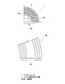
次に、前述した第1及び第2の実施形態の変形例に係るアクチュエータについて説明する。図6は本変形例のアクチュエータの構成を模式的に示す断面図である。なお、図6においては、図1に示すアクチュエータ1の構成要素と同じものには、同じ符号を付し、その詳細な説明は省略する。図6に示すように、本変形例のアクチュエータ10は、イオン伝導性高分子層2を挟むように1対の電極層5a,5bが設けられており、更に各電極層5a,5b上には、金属導電層6a,6bが形成されている。このアクチュエータ10では、金属導電層6a,6bにリード線(図示せず)が接合され、電極層5a,5bは、金属導電層6a,6b及びリード線等を介して外部電源(図示せず)に接続される。
<3. Modification>
Next, actuators according to modifications of the first and second embodiments described above will be described. FIG. 6 is a cross-sectional view schematically showing the configuration of the actuator of this modification. In FIG. 6, the same components as those of the
[金属導電層6a,6b]
金属導電層6a,6bは、金又は白金等の導電性に優れ、酸化しにくい金属材料で形成することができる。また、その厚さは、特に限定されるものではないが、リード線からの電圧が電極層5a,5bに均等に印加されるように、連続した膜となる程度の厚さであることが望ましい。また、その形成方法も特に限定されるものではなく、めっき法、蒸着法及びスパッタ法等公知の製膜方法を適用することができる。
[Metal
The metal
本変形例のアクチュエータ10では、電極層5a,5b上に金属導電層6a,6bを設けているため、表面抵抗が充分に低くなり、アクチュエータ全体に均一に電圧が印加されることとなる。これにより、アクチュエータ全体を均一に変形させることができる。
In the
なお、本変形例では、図1に示す第1の実施形態のアクチュエータ1に、金属導電層6a,6bを設けた場合を例に説明しているが、当然ながら、前述した第2の実施形態のアクチュエータに適用した場合でも、同様の効果が得られる。また、本変形例のアクチュエータ10における上記以外の構成、動作及び効果は、前述した第1及び第2の実施形態のアクチュエータと同様である。
In this modification, the case where the metal
以下、本発明の実施例により、本発明の効果について具体的に説明する。先ず、本発明の実施例として、図1に示すアクチュエータ1を作製した。その際、イオン伝導性高分子層2を構成するイオン伝導性フィルムには、デュポン社製、イオン伝導性フィルム Nafion(登録商標) NRE−212 (厚さ:50μm,官能基:スルホ基)を使用した。また、電極層5a,5bを構成するイオン伝導性高分子には、デュポン社製 イオン交換樹脂 Nafion(登録商標)の分散液(DE2020,官能基:スルホ基)を使用し、カーボン粉末は比表面積が800m2/gのもの(カーボン粉末A)と1200m2/gのもの(カーボン粉末B)を使用した。
Hereinafter, the effects of the present invention will be described in detail by way of examples of the present invention. First, as an example of the present invention, an
そして、イオン伝導性高分子と各カーボン粉末とを、質量比で、1:1となるように調合し、更に、固形分濃度が5質量%となるように、エタノールを添加して希釈した。その後、この組成物を、アジター(往復型シェイカー)で8時間分散し、カーボン粉末の比表面積が異なる2種類の塗料を作製した。 And ion-conducting polymer and each carbon powder were prepared so that it might become 1: 1 by mass ratio, and also ethanol was added and diluted so that solid content concentration might be 5 mass%. Thereafter, this composition was dispersed with an agitator (reciprocating shaker) for 8 hours to prepare two types of paints having different specific surface areas of carbon powder.
次に、比表面積が小さいカーボン粉末Aを含む塗料を、スプレーコーターにより、イオン伝導性フィルムの両面に塗布し、乾燥させた後、ホットプレスにより熱処理を行った。この工程を繰り返し、厚さ25μmの内側電極層3a,3bを形成した。その後、同様の方法で、内側電極層3a,3b上に、比表面積が大きいカーボン粉末Bを含む塗料を塗布し、乾燥及び熱処理を行い、厚さ25μmの外側電極層4a,4bを形成した。そして、このイオン伝導性フィルムの両面に電極層を形成したものを、イミダゾリウム系イオン液体中に浸漬し、その内部にイオン液体を含浸させて、実施例のアクチュエータとした。
Next, the coating material containing the carbon powder A having a small specific surface area was applied to both surfaces of the ion conductive film by a spray coater, dried, and then heat-treated by hot pressing. This process was repeated to form
また、本発明の比較例として、図5に示す従来のアクチュエータ100を作製した。その際、電極層105a,105bに含有するカーボン粉末を、比表面積が800m2/gのもののみにした以外は、前述した実施例のアクチュエータと同様にした。
Further, as a comparative example of the present invention, a
次に、前述した方法で作製した実施例及び比較例のアクチュエータの各電極層5a,5b,105a,105bにリード線を接続し、その特性を確認した。具体的には、アクチュエータの一端を固定し、1対の電極層それぞれに印加するプラス又はマイナスの電位を0.1Hzの周期で切り替えながら、電極層間に2Vの電圧を印加し、固定した根元から15mm離れた位置の変形量をレーザー変位計で測定した。また、各電極層へのプラス又はマイナス電位の印加切り替えを1Hzとして、同様に変形量を測定した。その結果、本実施例のアクチュエータは、比較例のアクチュエータに比べて、高効率で、変形量が大きいことが確認された。
Next, lead wires were connected to the
1、10、100 アクチュエータ
2、12 イオン伝導性高分子層
3a、3b 内側電極層
4a、4b 外側電極層
5a、5b、105a、105b 電極層
6a、6b 金属導電層
1, 10, 100
Claims (7)
該イオン伝導性高分子層の両面に設けられ、少なくともイオン伝導性高分子及び2種以上のカーボン粉末を含有する1対の電極層と、
前記イオン伝導性高分子層及び前記電極層に含有されるイオン液体と、を備え、
前記電極層は、より多くのイオンが集まるカーボン粉末が外側に存在し、内側よりも外側の方が電圧印加時の膨潤量が大きいアクチュエータ。 An ion conductive polymer layer made of an ion conductive polymer;
A pair of electrode layers provided on both surfaces of the ion conductive polymer layer and containing at least an ion conductive polymer and two or more carbon powders ;
An ionic liquid contained in the ion conductive polymer layer and the electrode layer,
The electrode layer is an actuator in which carbon powder that collects more ions is present on the outer side, and the outer side is larger than the inner side in the amount of swelling during voltage application .
Priority Applications (3)
| Application Number | Priority Date | Filing Date | Title |
|---|---|---|---|
| JP2009084104A JP5487678B2 (en) | 2009-03-31 | 2009-03-31 | Actuator |
| US12/724,532 US8350448B2 (en) | 2009-03-31 | 2010-03-16 | Actuator |
| CN201010145128.9A CN101854128B (en) | 2009-03-31 | 2010-03-24 | Actuator |
Applications Claiming Priority (1)
| Application Number | Priority Date | Filing Date | Title |
|---|---|---|---|
| JP2009084104A JP5487678B2 (en) | 2009-03-31 | 2009-03-31 | Actuator |
Publications (3)
| Publication Number | Publication Date |
|---|---|
| JP2010239732A JP2010239732A (en) | 2010-10-21 |
| JP2010239732A5 JP2010239732A5 (en) | 2012-04-12 |
| JP5487678B2 true JP5487678B2 (en) | 2014-05-07 |
Family
ID=42783264
Family Applications (1)
| Application Number | Title | Priority Date | Filing Date |
|---|---|---|---|
| JP2009084104A Active JP5487678B2 (en) | 2009-03-31 | 2009-03-31 | Actuator |
Country Status (3)
| Country | Link |
|---|---|
| US (1) | US8350448B2 (en) |
| JP (1) | JP5487678B2 (en) |
| CN (1) | CN101854128B (en) |
Families Citing this family (8)
| Publication number | Priority date | Publication date | Assignee | Title |
|---|---|---|---|---|
| JP5402140B2 (en) * | 2009-03-24 | 2014-01-29 | ソニー株式会社 | Actuator |
| JP2013062964A (en) * | 2011-09-14 | 2013-04-04 | Seiko Epson Corp | Actuator and method of manufacturing the same |
| JP6030841B2 (en) * | 2012-03-26 | 2016-11-24 | 住友理工株式会社 | Capacitive sensor |
| CN104114567B (en) | 2012-03-30 | 2016-06-22 | 住友理工株式会社 | Reactive ion liquid and employ its ion immobilization metal oxide particle, ion immobilization elastomer and transducer |
| JP6322900B2 (en) * | 2013-04-26 | 2018-05-16 | デクセリアルズ株式会社 | POLYMER ELEMENT, ITS MANUFACTURING METHOD, LENS MODULE, AND IMAGING DEVICE |
| JP6296530B2 (en) | 2013-07-18 | 2018-03-20 | 国立研究開発法人科学技術振興機構 | Biocompatible electrode structure and manufacturing method thereof, and device and manufacturing method thereof |
| WO2016208385A1 (en) * | 2015-06-23 | 2016-12-29 | 富士フイルム株式会社 | Electroacoustic conversion film and electroacoustic transducer |
| CN108630340B (en) * | 2017-03-22 | 2020-06-26 | 北京赛特超润界面科技有限公司 | Preparation method of PEDOT (Poly ethylene terephthalate): PSS (Polytetrafluoroethylene) @ ionic liquid gel composite self-supporting flexible transparent electrode |
Family Cites Families (28)
| Publication number | Priority date | Publication date | Assignee | Title |
|---|---|---|---|---|
| US5977685A (en) * | 1996-02-15 | 1999-11-02 | Nitta Corporation | Polyurethane elastomer actuator |
| US6545384B1 (en) * | 1997-02-07 | 2003-04-08 | Sri International | Electroactive polymer devices |
| AU2003254887A1 (en) * | 2002-08-09 | 2004-02-25 | Eamex Corporation | Process for producing conductive polymer |
| US7038357B2 (en) * | 2003-08-21 | 2006-05-02 | Engineering Services Inc. | Stretched rolled electroactive polymer transducers and method of producing same |
| US6876125B2 (en) * | 2003-08-26 | 2005-04-05 | Delphi Technologies, Inc. | Elastomeric polyphosphazene transducers, methods of making, and methods of use thereof |
| JP4038685B2 (en) * | 2003-12-08 | 2008-01-30 | 独立行政法人科学技術振興機構 | Actuator element |
| JP2005176412A (en) * | 2003-12-08 | 2005-06-30 | Hitachi Ltd | Actuator film material, actuator film, and actuator using it |
| JP4277103B2 (en) * | 2004-02-03 | 2009-06-10 | 国立大学法人信州大学 | Polymer actuator using carbon nanofibers |
| EP1784890A4 (en) * | 2004-06-14 | 2010-04-07 | Massachusetts Inst Technology | Electrochemical methods, devices, and structures |
| US20060266642A1 (en) * | 2005-03-14 | 2006-11-30 | Barbar Akle | Direct assembly process for fabrication of ionomeric polymer devices |
| JP3959104B2 (en) * | 2005-08-05 | 2007-08-15 | 松下電器産業株式会社 | Polymer actuator |
| JP4802680B2 (en) * | 2005-11-18 | 2011-10-26 | ソニー株式会社 | Actuator |
| US8574716B2 (en) * | 2006-01-23 | 2013-11-05 | Hitachi Chemical Co., Ltd. | Ionic polymer devices and methods of fabricating the same |
| US20070184238A1 (en) * | 2006-02-06 | 2007-08-09 | Energy Related Devices, Inc. | Laminate actuators and valves |
| US7909037B2 (en) * | 2006-04-20 | 2011-03-22 | Pavad Medical | Tethered airway implants and methods of using the same |
| JP5156940B2 (en) | 2006-06-08 | 2013-03-06 | 国立大学法人福井大学 | Polymer actuator and manufacturing method thereof |
| CA2657435A1 (en) * | 2006-07-10 | 2008-07-03 | Medipacs, Inc. | Super elastic epoxy hydrogel |
| DE602007012262D1 (en) * | 2006-07-26 | 2011-03-10 | Massachusetts Inst Technology | ELECTROCHEMICAL ACTUATOR |
| JP2008086185A (en) | 2006-08-30 | 2008-04-10 | Eamex Co | Polymer actuator element and manufacturing method therefor |
| JP4946570B2 (en) | 2007-03-29 | 2012-06-06 | Tdk株式会社 | Polymer actuator |
| JP5186160B2 (en) * | 2007-08-31 | 2013-04-17 | 東海ゴム工業株式会社 | Flexible electrode and actuator using the same |
| JP4501085B2 (en) * | 2007-10-04 | 2010-07-14 | ソニー株式会社 | Optical element module and imaging apparatus |
| CN101249959A (en) * | 2008-02-22 | 2008-08-27 | 哈尔滨工业大学深圳研究生院 | Carbon/carbon composite nano-tube material having large specific surface area and preparation thereof |
| WO2009122466A1 (en) * | 2008-04-04 | 2009-10-08 | パナソニック株式会社 | Electroconductive polymer actuator, process for producing the electroconductive polymer actuator, and method for driving the electroconductive polymer actuator |
| WO2010029992A1 (en) * | 2008-09-12 | 2010-03-18 | アルプス電気株式会社 | Polymer actuator |
| JP5402140B2 (en) * | 2009-03-24 | 2014-01-29 | ソニー株式会社 | Actuator |
| WO2010137604A1 (en) * | 2009-05-26 | 2010-12-02 | アルプス電気株式会社 | Macromolecule actuator device |
| JP5631042B2 (en) * | 2009-08-27 | 2014-11-26 | キヤノン株式会社 | Actuator |
-
2009
- 2009-03-31 JP JP2009084104A patent/JP5487678B2/en active Active
-
2010
- 2010-03-16 US US12/724,532 patent/US8350448B2/en active Active
- 2010-03-24 CN CN201010145128.9A patent/CN101854128B/en active Active
Also Published As
| Publication number | Publication date |
|---|---|
| JP2010239732A (en) | 2010-10-21 |
| US8350448B2 (en) | 2013-01-08 |
| CN101854128A (en) | 2010-10-06 |
| CN101854128B (en) | 2014-05-28 |
| US20100244633A1 (en) | 2010-09-30 |
Similar Documents
| Publication | Publication Date | Title |
|---|---|---|
| JP5487678B2 (en) | Actuator | |
| JP5402140B2 (en) | Actuator | |
| Yan et al. | Electroactive ionic soft actuators with monolithically integrated gold nanocomposite electrodes | |
| US7583009B2 (en) | Actuator | |
| Montazami et al. | Thickness dependence of curvature, strain, and response time in ionic electroactive polymer actuators fabricated via layer-by-layer assembly | |
| CN111854595B (en) | Ion sensor based on MXene electrode and preparation method thereof | |
| TW201108481A (en) | Electrically switchable polymer film arrangement and its use | |
| US20090032394A1 (en) | Ionic polymer devices and methods of fabricating the same | |
| JP5473483B2 (en) | Actuator | |
| US8378551B2 (en) | Actuator and method of manufacturing the same | |
| JP2016527559A (en) | Electrochromic membrane and related manufacturing method | |
| WO2011070988A1 (en) | Actuator | |
| CN110863962A (en) | Nano-particle agglomeration type nano-porous electrochemical driver and preparation and test method thereof | |
| Che et al. | An electrochemically driven actuator based on a nanostructured carbon material | |
| Eslamian et al. | Organic semiconductor nanotubes for electrochemical devices | |
| KR20100024041A (en) | Ionic polymer-metal composite and method of fabricating the same | |
| Meis et al. | Investigation of spray-coated silver-microparticle electrodes for ionic electroactive polymer actuators | |
| Jang et al. | Nanostructured metal/carbon hybrids for electrocatalysis by direct carbonization of inverse micelle multilayers | |
| JP5644737B2 (en) | Coating apparatus and electrode manufacturing method | |
| JP2018106882A (en) | Fuel cell and water electrolysis device | |
| KR20200074769A (en) | Conductive polymer coated graphene-AgNWs nano-composites electrode and method of manufacture therof | |
| Alekseyev et al. | The structure of silver modified flexible graphene electrodes for actuators in biomimetic systems | |
| Wu et al. | Advanced ionic actuators with high-performance and high-reproducibility based on free-standing bacterial cellulose-reinforced poly (diallyldimethylammonium chloride) membranes and PEDOT/PSS electrodes | |
| JP6420192B2 (en) | Carbon-containing film, method for producing carbon-containing film, polymer actuator element, and method for producing polymer actuator element | |
| JP5233068B2 (en) | Actuator, brake device, fluid control device, lens position adjusting device |
Legal Events
| Date | Code | Title | Description |
|---|---|---|---|
| A521 | Request for written amendment filed |
Free format text: JAPANESE INTERMEDIATE CODE: A523 Effective date: 20120229 |
|
| A621 | Written request for application examination |
Free format text: JAPANESE INTERMEDIATE CODE: A621 Effective date: 20120229 |
|
| A977 | Report on retrieval |
Free format text: JAPANESE INTERMEDIATE CODE: A971007 Effective date: 20130612 |
|
| A131 | Notification of reasons for refusal |
Free format text: JAPANESE INTERMEDIATE CODE: A131 Effective date: 20130618 |
|
| A521 | Request for written amendment filed |
Free format text: JAPANESE INTERMEDIATE CODE: A523 Effective date: 20130819 |
|
| TRDD | Decision of grant or rejection written | ||
| A01 | Written decision to grant a patent or to grant a registration (utility model) |
Free format text: JAPANESE INTERMEDIATE CODE: A01 Effective date: 20140128 |
|
| A61 | First payment of annual fees (during grant procedure) |
Free format text: JAPANESE INTERMEDIATE CODE: A61 Effective date: 20140210 |
|
| R151 | Written notification of patent or utility model registration |
Ref document number: 5487678 Country of ref document: JP Free format text: JAPANESE INTERMEDIATE CODE: R151 |
|
| S111 | Request for change of ownership or part of ownership |
Free format text: JAPANESE INTERMEDIATE CODE: R313113 |
|
| R350 | Written notification of registration of transfer |
Free format text: JAPANESE INTERMEDIATE CODE: R350 |
|
| R250 | Receipt of annual fees |
Free format text: JAPANESE INTERMEDIATE CODE: R250 |
|
| R250 | Receipt of annual fees |
Free format text: JAPANESE INTERMEDIATE CODE: R250 |
|
| R250 | Receipt of annual fees |
Free format text: JAPANESE INTERMEDIATE CODE: R250 |
|
| R250 | Receipt of annual fees |
Free format text: JAPANESE INTERMEDIATE CODE: R250 |
|
| R250 | Receipt of annual fees |
Free format text: JAPANESE INTERMEDIATE CODE: R250 |
|
| R250 | Receipt of annual fees |
Free format text: JAPANESE INTERMEDIATE CODE: R250 |
|
| R250 | Receipt of annual fees |
Free format text: JAPANESE INTERMEDIATE CODE: R250 |
|
| R250 | Receipt of annual fees |
Free format text: JAPANESE INTERMEDIATE CODE: R250 |