JP5486205B2 - Illumination method using task lighting apparatus and task lighting apparatus - Google Patents
Illumination method using task lighting apparatus and task lighting apparatus Download PDFInfo
- Publication number
- JP5486205B2 JP5486205B2 JP2009075796A JP2009075796A JP5486205B2 JP 5486205 B2 JP5486205 B2 JP 5486205B2 JP 2009075796 A JP2009075796 A JP 2009075796A JP 2009075796 A JP2009075796 A JP 2009075796A JP 5486205 B2 JP5486205 B2 JP 5486205B2
- Authority
- JP
- Japan
- Prior art keywords
- light
- face
- light emitting
- emitting unit
- task lighting
- Prior art date
- Legal status (The legal status is an assumption and is not a legal conclusion. Google has not performed a legal analysis and makes no representation as to the accuracy of the status listed.)
- Active
Links
Images


Classifications
-
- Y—GENERAL TAGGING OF NEW TECHNOLOGICAL DEVELOPMENTS; GENERAL TAGGING OF CROSS-SECTIONAL TECHNOLOGIES SPANNING OVER SEVERAL SECTIONS OF THE IPC; TECHNICAL SUBJECTS COVERED BY FORMER USPC CROSS-REFERENCE ART COLLECTIONS [XRACs] AND DIGESTS
- Y02—TECHNOLOGIES OR APPLICATIONS FOR MITIGATION OR ADAPTATION AGAINST CLIMATE CHANGE
- Y02B—CLIMATE CHANGE MITIGATION TECHNOLOGIES RELATED TO BUILDINGS, e.g. HOUSING, HOUSE APPLIANCES OR RELATED END-USER APPLICATIONS
- Y02B20/00—Energy efficient lighting technologies, e.g. halogen lamps or gas discharge lamps
- Y02B20/40—Control techniques providing energy savings, e.g. smart controller or presence detection
Description
本発明は、タスク用照明器具によるサーカディアンリズムを整えるための照明方法及びそれに用いられるタスク用照明器具に関する。 The present invention relates to a lighting method for adjusting a circadian rhythm by a task lighting fixture and a task lighting fixture used therefor.
従来から、約24時間周期の生体リズムであるサーカディアンリズムを整えるために、日中、特に午前中に顔面に高照度の光を浴び、夕刻から夜間にかけて、特に遅い時間帯になるにつれ、できるだけ顔面に光を浴びないようにすることが人にとって重要であるとされている。 Traditionally, in order to adjust the circadian rhythm, which is a biological rhythm with a period of about 24 hours, the face is exposed to high illuminance light during the day, especially in the morning, and as the face becomes as late as possible, especially during the late hours from evening to night. It is said that it is important for people not to be exposed to light.
夜間に分泌され、サーカディアンリズムに関連すると考えられているホルモン、メラトニンは、光を浴びることでその分泌が抑制されることが従前から知られていたが、非特許文献1によれば、その作用に波長特性があり、波長の短い光でメラトニンの分泌がより抑制されると報告されている。一般に光は、相関色温度が高い程、短波長成分を多く含むので、夜間には、目に入射する光をできるだけ低い色温度の光にすることによって、メラトニン分泌の抑制が防止され、サーカディアンリズムの乱れが防がれる。逆に、日中に短波長の光を目に浴びることは、よりサーカディアンリズムを整える作用があることがわかってきている。従って、日中はできるだけ高い色温度の光をできるだけ高照度で目に浴びるようにし、夜間はできるだけ目に光を浴びないように、もし浴びるとしても、できるだけ低い色温度の光をできるだけ低照度で浴びるようにすることが望ましい。 A hormone secreted at night and thought to be related to circadian rhythm, melatonin, was previously known to be secreted by exposure to light. Has a wavelength characteristic, and it is reported that melatonin secretion is further suppressed by light having a short wavelength. In general, the higher the correlated color temperature, the more the short wavelength component, the more the light incident on the eyes, the lower the color temperature, so that the suppression of melatonin secretion is prevented and the circadian rhythm is suppressed. Disturbance is prevented. Conversely, it has been found that exposure to light of short wavelengths during the day has the effect of adjusting the circadian rhythm. Therefore, try to keep the light of the highest possible color temperature in the daytime with the highest possible illuminance, and to keep the light out of the eyes as much as possible at night. It is desirable to make it soak.
サーカディアンリズムを考慮した照明装置として、照明器具を室内の高所と低所に設置し、高所に設置した照明器具を高色温度で点灯し、低所に設置した照明器具を低色温度で点灯する制御をする室内照明装置が知られている(例えば、特許文献1参照)。 As lighting equipment that takes into account circadian rhythms, lighting fixtures are installed at high and low indoor locations, lighting fixtures installed at high locations are lit at high color temperatures, and lighting fixtures installed at low locations are at low color temperatures. An indoor lighting device that controls lighting is known (for example, see Patent Document 1).
しかしながら、上述した室内照明装置においては、夜間のできるだけ光を浴びたくない時間帯において、低所すなわち顔面に近い位置の照明器具が点灯するため、目が必要以上に光を浴び、サーカディアンリズムが乱れる。また、日中に点灯する高色温度の照明器具が高所に設置されており、顔面からの距離が遠いために光のロスが大きく、省エネルギーでない。また、高所と低所の2箇所に設置した照明器具を制御する必要があり、高コストである。 However, in the indoor lighting device described above, the lighting fixture in a low place, that is, a position close to the face, is lit in a time zone where the light is not desired as much as possible at night, so the eyes are exposed to light more than necessary, and the circadian rhythm is disturbed. . In addition, lighting devices with high color temperature that are lit during the day are installed in high places, and the distance from the face is far away, so the loss of light is large and energy is not saved. Moreover, it is necessary to control the lighting fixtures installed at two places, the high place and the low place, which is expensive.
一方、室内空間全体を均一照度で照明する全般照明と異なり、空間全体を照明するアンビエント照明と、机上面等の作業面を照明するタスク照明とに分けたタスクアンドアンビエント照明が知られている。例えば、図23に示されるように、アンビエント照明のためのアンビエント用照明器具102が天井101に配設され、タスク照明のためのタスク用照明器具103が机上に立設される。タスクアンドアンビエント照明は、アンビエント照明の照度を抑え、タスク照明で視作業に必要な照度を作業面に確保することにより、省エネルギーを図っている。
On the other hand, unlike general illumination that illuminates the entire indoor space with uniform illuminance, task-and-ambient illumination that is divided into ambient illumination that illuminates the entire space and task illumination that illuminates a work surface such as a desk surface is known. For example, as shown in FIG. 23, an
上述したタスクアンドアンビエント照明は、全体として省エネルギーに寄与するが、空間全体の照度を低下して作業面に光を集中するため、日中において顔面への光が不足する傾向があり、サーカディアンリズムを乱す虞がある。一方、夕刻と夜間において、作業面からの反射光により顔面へ不要な量の光が供給され、サーカディアンリズムが乱れる虞がある。 The task-and-ambient lighting described above contributes to energy conservation as a whole, but it reduces the illuminance of the entire space and concentrates the light on the work surface. There is a risk of disturbance. On the other hand, in the evening and at night, an unnecessary amount of light is supplied to the face by the reflected light from the work surface, which may disturb the circadian rhythm.
本発明は、上記問題を解決するものであり、タスクアンドアンビエント照明に用いられるタスク用照明器具において、省エネルギーとサーカディアンリズムの調整を両立させることを目的とする。 This invention solves the said problem, and aims at making energy saving and adjustment of a circadian rhythm compatible in the task lighting fixture used for task and ambient lighting.
上記目的を達成するために請求項1の発明は、作業面を照明するタスク用照明器具による照明方法であって、前記タスク用照明器具が照明をする時間帯は、少なくとも第1の作業時間帯と第2の作業時間帯とに分けられ、前記タスク用照明器具は、前記第1の作業時間帯では、作業をする人の顔面に直射光を照射し、その直射光は、顔面鉛直面の単位面積当たり、メラトニンの分泌を抑制する該直射光の放射束が700W以上とされ、前記第2の作業時間帯では、顔面に直射光を照射せず、作業面に照射する照明光は、色温度が5000K以下とされるものである。
In order to achieve the above object, the invention according to
ここで、前記第1の作業時間帯は、例えば、日中の時間帯であり、前記第2の作業時間帯は、例えば、夕刻から夜間にかけての時間帯である。 Here, the first work time zone is, for example, a day time zone, and the second work time zone is, for example, a time zone from evening to night.
請求項2の発明は、請求項1に記載のタスク用照明器具による照明方法において、前記タスク用照明器具は、顔面に直射光を照射する発光部を備え、前記発光部は、平均輝度が20000cd/m2以下とされるものである。 According to a second aspect of the present invention, in the illumination method using the task lighting device according to the first aspect, the task lighting device includes a light emitting unit that irradiates the face with direct light, and the light emitting unit has an average luminance of 20000 cd. / M 2 or less.
請求項3の発明は、作業面を照明するタスク用照明器具であって、前記タスク用照明器具は、作業をする人の顔面に直射光を照射する顔面向け発光部と、作業面に照明光を照射する作業面向け発光部と、を備え、前記直射光は、顔面鉛直面の単位面積当たり、メラトニンの分泌を抑制する該直射光の放射束が700W以上とされ、前記照明光は、色温度が5000K以下とされるものである。
The invention of
請求項4の発明は、請求項3に記載のタスク用照明器具において、前記顔面向け発光部は、特定の波長域の光を透過させるフィルタを備え、該フィルタを介して顔面に直射光を照射するものである。 According to a fourth aspect of the present invention, in the task lighting device according to the third aspect, the face light emitting section includes a filter that transmits light in a specific wavelength range, and direct light is irradiated onto the face through the filter. To do.
請求項5の発明は、請求項3に記載のタスク用照明器具において、前記顔面向け発光部及び前記作業面向け発光部は、一体の発光部であって、前記発光部は、作業面に対する位置を変化させることによって、顔面に対する直射光の照射の有無を切り替えるものである。 According to a fifth aspect of the present invention, in the task lighting device according to the third aspect, the light emitting unit for the face and the light emitting unit for the work surface are an integrated light emitting unit, and the light emitting unit is positioned relative to the work surface. By changing, the presence or absence of direct light irradiation on the face is switched.
請求項6の発明は、請求項3に記載のタスク用照明器具において、複数の前記タスク用照明器具が同一系統のダクトから給電されるものである。 A sixth aspect of the present invention is the task lighting fixture according to the third aspect, wherein the plurality of task lighting fixtures are fed from a duct of the same system.
請求項7の発明は、請求項3に記載のタスク用照明器具において、照明光の平均演色評価指数(Ra)が80以上とされるものである。 According to a seventh aspect of the present invention, in the task lighting fixture according to the third aspect, the average color rendering index (Ra) of the illumination light is 80 or more.
請求項1の発明によれば、タスク用照明器具によって省エネルギーのタスクアンドアンビエント照明を行い、タスク用照明器具が照射する光の照射を時間帯に応じて変えることによって、第1の作業時間帯ではサーカディアンリズムの調整効果を得て、第2の作業時間帯ではサーカディアンリズムへの影響を小さくするので、省エネルギーとサーカディアンリズムの調整を両立させることができる。 According to the first aspect of the present invention, energy saving task-and-ambient illumination is performed by the task lighting device, and the irradiation of the light emitted by the task lighting device is changed according to the time zone. Since the circadian rhythm adjustment effect is obtained and the influence on the circadian rhythm is reduced in the second work time zone, both energy saving and circadian rhythm adjustment can be achieved.
請求項2の発明によれば、直射光によるグレアを抑制することができる。
According to invention of
請求項3の発明によれば、請求項1の発明と同じ効果を得ることができる。
According to the invention of
請求項4の発明によれば、可視光の波長域のうち、比較的短い波長域の透過率が高く、長い波長域の透過率が低いフィルタを選択することによって、短波長の直射光でサーカディアンリズム調整効果を維持すると共に、短波長以外の直射光をカットして平均輝度を下げ、グレアを抑制することができる。
According to the invention of
請求項5の発明によれば、顔面に対する直射光の照射と作業面に対する照明光の照射を一体の発光部で兼用するので、器具構成が簡易化される。
According to the invention of
請求項6の発明によれば、複数のタスク用照明器具を一括して点灯、消灯等することができる。
According to the invention of
請求項7の発明によれば、作業面の視認性を維持することができる。
According to the invention of
(第1の実施形態)
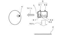
本発明の第1の実施形態に係るタスク用照明器具(以下、照明器具という)による照明方法を図1乃至図6を参照して説明する。図1に示されるように、照明器具1は、作業面2の近傍に立設された支持部3に取り付けられ、作業面2を照明する。照明器具1による照明時間帯は、少なくとも第1の作業時間帯と第2の作業時間帯とに分けられている。第1の作業時間帯は、日中、特に午前中の時間帯であり、第2の作業時間帯は、夕刻から夜間にかけての時間帯である。
(First embodiment)
A lighting method using a task lighting device (hereinafter referred to as a lighting device) according to a first embodiment of the present invention will be described with reference to FIGS. As shown in FIG. 1, the
照明器具1は、作業をする人すなわち使用者4の顔面に直射光51Lを照射する顔面向け発光部51と、作業面2に照明光52Lを照射する作業面向け発光部52とを備える。顔面向け発光部51と作業面向け発光部52とは、一体であっても、別体として構成してもよい(総称して発光部5という)。発光部5は、蛍光灯又はLED等の光源を有する。なお、51Lと52Lの閉曲線は、それぞれ、顔面向け発光部51と作業面向け発光部52の配光曲線を示す。
The
照明器具1は、第1の作業時間帯、例えば日中では、使用者4の顔面に直射光を照射する。その直射光は、顔面鉛直面の単位面積当たりのメラトニンの分泌を抑制する放射束(以下、メラトニン作用放射束)が700W(ワット:以下、単位表記は省略)以上とされる。第2の作業時間帯、例えば夕刻〜夜間では、顔面への直射光は、消灯又は減光される。特に夜間は、顔面への直射光が消灯されることが望ましい。第2の作業時間帯における作業面2に照射する照明光は、相関色温度が5000K以下とされ、照明光の作業面からの反射光が目に反射することもあり得るため、3000K以下が望ましい。
The
メラトニン作用放射束Mは、光束をΦ、相対メラトニン作用係数をmとすると、下記の数式1により求められる。
The melatonin acting radiant flux M is obtained by the
![]()
![]()
この相対メラトニン作用係数mは、k1、k2を定数、λを波長、B(λ)をアクションスペクトル、V(λ)を標準視感効率、S(λ)を照明器具1からの分光放射束、Swhite(λ)を蛍光灯等の任意の一般的な白色光源の分光放射束とすると、下記の数式2により求められる。
The relative melatonin action coefficient m is k 1 , k 2 are constants, λ is a wavelength, B (λ) is an action spectrum, V (λ) is a standard luminous efficiency, and S (λ) is a spectral emission from the

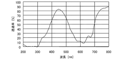
図2に示されるように、メラトニン抑制に関するアクションスペクトルB(λ)は、400nm乃至600nmの波長域において、波長λに対して上に凸の曲線となり、波長λが464nmにピークを有する(非特許文献1参照)。この曲線は、実験結果を4次関数で近似したものであり、決定係数R2すなわち相関係数Rの自乗が0.91である。 As shown in FIG. 2, the action spectrum B (λ) relating to melatonin suppression becomes a convex curve upward with respect to the wavelength λ in the wavelength range of 400 nm to 600 nm, and the wavelength λ has a peak at 464 nm (non-patented). Reference 1). This curve approximates the experimental result with a quartic function, and the square of the determination coefficient R 2, that is, the correlation coefficient R is 0.91.
顔面に直射光を照射する顔面向け発光部51は、その平均輝度が20000cd/m2以下とされ、10000cd/m2以下が望ましく、5000cd/m2以下がさらに望ましい。
Facial for emitting
図3は、上記照明器具1による実験結果を示す。ここに、メラトニン作用放射束、作業面色温度及び発光面輝度に対する、日中の生体リズム(サーカディアンリズム)調整効果、夜間の生体リズムへの影響及び被験者グレア感を示す。被験者の顔面に対する直射光のメラトニン作用放射束は、400から900まで100刻みに変化させ、作業面に対する照明光の色温度は、3000Kから7000Kまで1000K刻みに変化させ、発光部の発光面輝度は、照明光の色温度に応じて変化させた。
FIG. 3 shows a result of the experiment using the
日中の生体リズム調整効果は、「効果大」(◎)、「効果中程度」(○)、「効果小」(△)、「効果なし」(×)の4段階で評価した。実験結果によれば、メラトニン作用放射束が700と800のときに評価が「効果中程度」(○)となり、メラトニン作用放射束が900のときに評価が「効果大」(◎)となった。すなわち、メラトニン作用放射束を700以上にすれは、日中の生体リズム調整効果が得られる。 The biological rhythm adjustment effect during the day was evaluated in four stages: “high effect” (◎), “medium effect” (◯), “small effect” (Δ), and “no effect” (×). According to the experimental results, when the melatonin radiant flux was 700 and 800, the evaluation was “medium effect” (◯), and when the melatonin radiant flux was 900, the evaluation was “high effect” (◎). . That is, if the melatonin action radiant flux is set to 700 or more, the biological rhythm adjustment effect during the day can be obtained.
夜間の生体リズムへの影響は、「影響なし」(◎)、「影響小」(○)、「影響中程度」(△)、「影響大」(×)の4段階で評価した。実験結果によれば、作業面色温度が5000Kと4000Kのときに評価が「影響小」(○)となり、作業面色温度が3000Kのときに評価が「影響なし」(◎)となった。すなわち、作業面色温度を5000K以下にすれば、夜間の生体リズムへの影響が小さい。 The influence on the biological rhythm at night was evaluated in four stages: “no influence” (◎), “small influence” (◯), “medium influence” (Δ), and “high influence” (×). According to the experimental results, the evaluation was “small influence” (◯) when the work surface color temperatures were 5000K and 4000K, and the evaluation was “no effect” (◎) when the work surface color temperature was 3000K. That is, if the work surface color temperature is set to 5000K or less, the influence on the nighttime biological rhythm is small.
被験者のグレア感は、「グレア感なし」(○)、「グレア感中程度」(△)、「グレア感大」(×)の3段階で評価した。実験結果によれば、発光面輝度が18000cd/m2と20000cd/m2のときに評価が「グレア感なし」(○)となった。すなわち、発光面輝度を20000cd/m2以下にすれば、照明器具によるグレアが抑制される。 The subject's glare feeling was evaluated in three stages: “no glare feeling” (◯), “medium glare feeling” (Δ), and “large glare feeling” (×). According to the experimental results, the evaluation was “no glare” (◯) when the light emitting surface luminance was 18000 cd / m 2 and 20000 cd / m 2 . That is, when the luminance of the light emitting surface is set to 20000 cd / m 2 or less, glare due to the lighting fixture is suppressed.
上述したように、照明器具1によって省エネルギーのタスクアンドアンビエント照明を行い、照明器具1が照射する光の照射を時間帯に応じて変えることによって、第1の作業時間帯ではサーカディアンリズムの調整効果を得て、第2の作業時間帯ではサーカディアンリズムへの影響を小さくするので、省エネルギーとサーカディアンリズムの調整を両立させることができる。また、作業をする人の顔面に直射光を照射する発光部の平均輝度を所定値(20000cd/m2)以下にするので、直射光によるグレアを抑制することができる。
As described above, energy-saving task-and-ambient lighting is performed by the
作業をする人の顔面に直射光を照射する発光部は、光源の光出力を制限することによって平均輝度を20000cd/m2以下にしてもよいが、フィルタによって特定波長域以外の直射光を減衰させることによって平均輝度を20000cd/m2以下にしてもよい。 The light emitting unit that irradiates the face of the person who performs the work with direct light may limit the light output of the light source to reduce the average luminance to 20000 cd / m 2 or less, but the filter attenuates direct light outside the specific wavelength range. The average luminance may be set to 20000 cd / m 2 or less.
例えば、図4に示されるように、発光部5は、使用者4の顔面に対する直射光51Lと作業面2に対する照明光52Lを照射する光源6と、特定の波長域の光を透過させるフィルタ7とを備え、フィルタ7を介して顔面に直射光51Lを照射する。
For example, as shown in FIG. 4, the
また、図5に示されるように、発光部5は、使用者4の顔面に直射光51Lを照射する光源61を有する顔面向け発光部51と、作業面2に照明光52Lを照射する光源62を有する作業面向け発光部52とを備え、特定の波長域の光を透過させるフィルタ7が顔面向け発光部51に設けられ、フィルタ7を介して顔面に直射光51Lを照射するようにしてもよい。
As shown in FIG. 5, the
フィルタ7は、図6に示されるように、可視光の波長域のうち、比較的短い波長域の透過率が高く、それよりも長い波長域の透過率が低いものが選択される。これにより、短波長の直射光によるサーカディアンリズム調整効果を維持すると共に、短波長以外の直射光をカットして平均輝度を下げ、グレアを抑制することができる。
As shown in FIG. 6, the
(第2の実施形態)
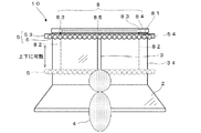
本発明の第2の実施形態に係る照明器具を図7乃至図16を参照して説明する。図7に示されるように、本実施形態の照明器具10は、使用者の顔面への直射光及び作業面への照明光を照射する発光部5と、発光部5を調光制御する第1の制御部54と、発光部5を上下動自在に支持する支持部3と、発光部5を可動させる可動部8と、発光部5の可動を制御する第2の制御部81と、発光部の作業面に対する高さを検知する高さ検知部9とを備える。
(Second Embodiment)
A lighting apparatus according to a second embodiment of the present invention will be described with reference to FIGS. As shown in FIG. 7, the
図8及び図9に示されるように、発光部5は、使用者4に向かって左右に長い長尺状の灯具53と、灯具53に取り付けられた蛍光灯、LED又は有機EL等から成る光源6とを有し、使用者4の顔面に直射光を照射する顔面向け発光部と、作業面2に照明光を照射する作業面向け発光部とを兼ねた一体のものとして構成される。第1の制御部54は、インバータ等を有し、光源6の光出力を調整して発光部5を調光制御する。
As shown in FIGS. 8 and 9, the
支持部3は、例えば、作業面2の奥位置に立設されたパーティション34に上下方向に取り付けられたガイドレールであり、発光部5を上下に可動自在に支持する。灯具53は、ロープ又はワイヤ等の索体82によってパーティション34の上部に取り付けられたドラム83から吊り下げられる。ドラム83は、モータ84によって回転され、索体82を巻き取って灯具53を支持部3に沿って上昇させ、逆回転されることによって灯具53を下降させる。このドラム83は、パーティション34の左右に一対として設けられており、両ドラム83を連結する回転軸85によって回転が同期される。これらのモータ84、ドラム83、回転軸85及び索体82が、可動部8を構成する。第2の制御部81は、モータ84の回転及び停止を制御して、発光部5の作業面2に対する位置を制御する。
The
高さ検知部9は、例えばリミットスイッチであり、支持部3の上端及び下端の近傍に取り付けられ、発光部5が上位置又は下位置にあることを検知する。この上位置は、着席した使用者4の目線よりも高い位置に設定され、下位置は、使用者4の目線よりも低く作業面2よりも高い位置に設定される。
The
上記のように構成された照明器具10は、作業面2に対する発光部5の位置を変化させることによって、使用者4の顔面に対する直射光の照射の有無を切り替える。第1の作業時間帯、例えば日中では、発光部5(実線で示す)は、着席した使用者4の目線よりも高い位置(上位置)に上昇され、使用者4の顔面と作業面2に光を照射する。第2の作業時間帯、例えば夕刻〜夜間では、発光部5(2点鎖線で示す)は、着席した使用者4の目線よりも低い位置(下位置)に下降され、使用者4の顔面に光を照射せず、作業面2のみに光を照射する。発光部5は、下位置にあるとき、作業面2との距離が近いので、第1の制御部54によって光源6の光出力を下げてもよい。発光部5の高さを変化させることにより、作業面2の照度を確保しつつ、顔面への直射光の有無を切り替え、顔面への照度が可変とされる。発光部5の上昇と下降は、タイマー等により自動制御してもよいし、手動で操作してもよい。
The
このように、顔面に対する直射光の照射と作業面2に対する照明光の照射を一体の発光部5で兼用するので、器具構成が簡易化される。
In this way, since the integrated
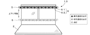
次に、発光部5が照射する光のメラトニン作用放射束及び色温度の切替について説明する。図10に示されるように、発光部5の光源6は、高色温度の光源61と低色温度又は白色の光源62とから成り、例えば、複数の高色温度の光源61と低色温度又は白色の光源62とが交互に配列されている。
Next, switching of the melatonin action radiant flux and color temperature of the light emitted by the
第1の作業時間帯では、発光部5は、第1の制御部54によって高色温度の光源61を点灯すると共に低色温度又は白色の光源62を消灯し、高色温度の光を照射する。第2の作業時間帯では、発光部5は、低色温度又は白色の光源62を点灯すると共に高色温度の光源61を消灯し、低色温度又は白色の光を照射する。高色温度の光源61と低色温度又は白色の光源62の光源の点灯及び消灯は、発光部5の位置を高さ検知部9によって検知して自動で切り替えてもよいし、手動で切り替えてもよい。
In the first work time zone, the
図11に示されるように、第1の作業時間帯では、発光部5は、着席した使用者4の目線よりも高い位置から、使用者4の顔面と作業面2に高色温度の光を照射する。このときに顔面に照射される直射光は、顔面鉛直面の単位面積当たりのメラトニン作用放射束が700以上とされる。第2の作業時間帯では、発光部5は、着席した使用者4の目線よりも低い位置から、作業面2のみに低色温度又は白色の光を照射する。このときに作業面2に照射される照明光は、色温度が5000K以下とされる。
As shown in FIG. 11, in the first work time zone, the
この照明光は、平均演色評価指数(Ra)を80以上とすることが望ましい。これにより、作業面の視認性を維持することができる。 The illumination light preferably has an average color rendering index (Ra) of 80 or more. Thereby, the visibility of the work surface can be maintained.
また、図12に示されるように、第1の作業時間帯では、発光部5は、高色温度の光源61と低色温度又は白色の光源62を共に点灯し、高色温度かつ高照度の光を照射するようにしてもよい。第2の作業時間帯では、発光部5は、高色温度の光源61を消灯して低色温度又は白色の光源62を点灯し、低色温度又は白色の光を照射する。
In addition, as shown in FIG. 12, in the first work time zone, the
また、図13に示されるように、発光部5に色温度が可変の光源63を用い、第1の制御部54で光源63の光出力と色温度を制御するように構成してもよい。第1の作業時間帯では、発光部5は、光源63が、高色温度の光を照射する。第2の作業時間帯では、同じ光源63が、低色温度又は白色の光を照射する。光源63の光出力は、第1の作業時間帯よりも第2の作業時間帯のほうが低くされる。
Further, as shown in FIG. 13, a
色温度が可変の光源63は、例えば、図14に示されるように、赤色(R)、緑色(G)及び青色(B)の発光ダイオード(LED)を組み合わせたものであり、各LEDからの光が混色された光を照射する。このRGBの各LEDの光出力の調整により、光源63の色温度が可変とされる。
The
図15に示されるように、発光部5は、作業面2からの高さに応じて光源6の照射範囲を変えるように構成してもよい。灯具53は、光源6からの光を反射する反射板55を備える。発光部5は、その位置が下がると、灯具53又は反射板55を使用者4側に向けて回動させる。この回動は、発光部5の上下可動機構に連動して行われる。例えば、支持部3にラック・ギア、発光部5にピニオン・ギアを設け(図示せず)、発光部5の支持部3に沿った上下動によって、ピニオン・ギアを回転させ、その回転により減速ギアを介して反射板55を回動させる。これにより、作業面2の明るさのムラが低減される。なお、このラック・アンド・ピニオンを発光部5の上下可動機構として用いてもよい。
As shown in FIG. 15, the
また、図16に示されるように、発光部5を上下に動かすことに替えて、灯具53又は反射板55を回動することによって、使用者4の顔面に対する直射光の照射の有無を切り替えるように構成してもよい。例えば、第1の作業時間帯では、発光部5は、着席した使用者4の目線よりも高い位置から、使用者4の顔面と作業面2に光を照射する。第2の作業時間帯では、発光部5は、モータ等によって反射板55を作業面2の方向に回動し、同じ位置から作業面2のみに光を照射する。なお、本変形例の制御では、高さ検知部に替えて、反射板の角度を検知する角度検知部が用いられる。また、発光部5は、反射板55を回動することに替えて、反射板55を使用者4の顔面方向にせり出すように構成してもよい。
In addition, as shown in FIG. 16, instead of moving the
(第3の実施形態)
本発明の第3の実施形態に係る照明器具を図17乃至図19を参照して説明する。図17及び図18に示されるように、室内に複数の机41が配置されており、第1の照明ダクト56と、第2の照明ダクト57が、自立可能な支持部35によって机41の上方に略水平に支持される。各机41の机上面が作業面である。第1の照明ダクト56は、着席した使用者の目線よりも高い位置に支持され、第2の照明ダクト57は、着席した使用者の目線よりも低い位置に支持される。
(Third embodiment)
A lighting apparatus according to a third embodiment of the present invention will be described with reference to FIGS. As shown in FIG. 17 and FIG. 18, a plurality of
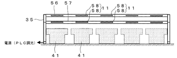
第1及び第2の照明ダクト56、57は、図19(a)に示されるダクトに、図19(b)で示される光源モジュール58が着脱自在に取り付けられたものである。光源モジュール58は、LED等から成る光源6を有し、本実施形態では照明器具11の発光部として機能する。第1及び第2の照明ダクト56、57には、複数の照明器具11が各机41に対応して配置される。同一系統のダクトに配置された照明器具11は、その系統のダクトから給電される。なお、ダクトには、図19(c)に示される人センサモジュール91及び図19(d)に示される明るさセンサモジュール92を取り付けてもよい。人センサモジュール91は、使用者の有無を検知し、明るさセンサモジュール92は、作業面の明るさを検知し、それらの検知結果は、光源モジュール58の点灯、調光、消灯の制御に用いられる。
In the first and
上記のように構成された照明器具11の動作について説明する。第1の作業時間帯では、第1の照明ダクト56に配置された光源モジュール58は、使用者の顔面と作業面に高色温度の光を照射する。このときに照射される光は、顔面鉛直面の単位面積当たりのメラトニン作用放射束が700以上とされる。第2の作業時間帯では、第1の照明ダクト56に配置された光源モジュール58は消灯し、第2の照明ダクト57に配置された光源モジュール58は、着席した使用者の目線よりも低い位置から、作業面のみに低色温度の光を照射する。このときに照射される光は、色温度が5000K以下とされる。光源モジュール58は、例えばPLC(電力線通信)によりアドレッシングを行って、点灯を自動制御してもよい。
Operation | movement of the lighting fixture 11 comprised as mentioned above is demonstrated. In the first work time zone, the
これにより、光源モジュール58の着脱によって照明器具11の増減が容易となり、また、複数の照明器具11を一括して点灯、消灯等することができる。
Accordingly, the lighting fixtures 11 can be easily increased or decreased by attaching and detaching the
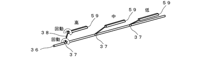
本実施形態の変形例に係る照明器具を図20乃至図22を参照して説明する。図20及び図21に示されるように、複数の第1の照明ダクト59を支持する支持バー36と、第2の照明ダクト57が、自立可能な支持部35によって机41の上方に略水平に支持される。第1の照明ダクト59は、各机41毎に配置され、着席した使用者の目線よりも高い位置に略水平に支持される。第2の照明ダクト57は、複数の机41に共通に設けられ、着席した使用者の目線よりも低い位置に支持される。
The lighting fixture which concerns on the modification of this embodiment is demonstrated with reference to FIG. As shown in FIGS. 20 and 21, the
図22に示されるように、各々の第1の照明ダクト59は、アーム38を介して支持バー36に枢設される。アーム38の一端は、支持バー36に着脱自在に取り付けられ、回動機構37によって支持バー36の周りを回動自在とされる。アーム38の他端には、第1の照明ダクト59が取り付けられ、第1の照明ダクト59は、支持バー36に対して平行保って回動自在である。第1の照明ダクト59は、アーム38及び支持バー36を介して給電される。これにより、第1の照明ダクト59は、作業面からの高さが個別に調整される。
As shown in FIG. 22, each
なお、本発明は、上記の実施形態の構成に限られず、発明の要旨を変更しない範囲で種々の変形が可能である。例えば、第2の実施形態において、発光部5を上下動させる機構は、クロスリンク等のリンク機構又はボールねじを用いたものであってもよい。
In addition, this invention is not restricted to the structure of said embodiment, A various deformation | transformation is possible in the range which does not change the summary of invention. For example, in the second embodiment, the mechanism for moving the
1、10、11 タスク用照明器具
5 発光部
51 顔面向け発光部
52 作業面向け発光部
7 フィルタ
56、57、59 ダクト
1, 10, 11
Claims (7)
前記タスク用照明器具が照明をする時間帯は、少なくとも第1の作業時間帯と第2の作業時間帯とに分けられ、
前記タスク用照明器具は、前記第1の作業時間帯では、作業をする人の顔面に直射光を照射し、その直射光は、顔面鉛直面の単位面積当たり、メラトニンの分泌を抑制する該直射光の放射束が700W以上とされ、
前記第2の作業時間帯では、顔面に直射光を照射せず、作業面に照射する照明光は、色温度が5000K以下とされることを特徴とするタスク用照明器具による照明方法。 A lighting method using a task lighting device for illuminating a work surface,
The time zone in which the task lighting device illuminates is divided into at least a first work time zone and a second work time zone,
The task lighting device irradiates the face of the person who performs the work with direct light in the first working time period, and the direct light suppresses the secretion of melatonin per unit area of the vertical face. The radiant flux of light is 700 W or more,
In the second working time zone, the illumination light by the task lighting device is characterized in that the direct illumination light is not applied to the face and the illumination light applied to the work surface has a color temperature of 5000K or less.
前記発光部は、平均輝度が20000cd/m2以下とされることを特徴とする請求項1に記載のタスク用照明器具による照明方法。 The task lighting device includes a light emitting unit that irradiates the face with direct light,
The lighting method according to claim 1, wherein the light emitting unit has an average luminance of 20000 cd / m 2 or less.
前記タスク用照明器具は、作業をする人の顔面に直射光を照射する顔面向け発光部と、作業面に照明光を照射する作業面向け発光部と、を備え、
前記直射光は、顔面鉛直面の単位面積当たり、メラトニンの分泌を抑制する該直射光の放射束が700W以上とされ、
前記照明光は、色温度が5000K以下とされることを特徴とするタスク用照明器具。 A task lighting device for illuminating a work surface,
The task lighting apparatus includes a light emitting unit for a face that irradiates the face of a person who performs the work with direct light, and a light emitting unit for the work surface that irradiates the work surface with illumination light.
The direct light has a radiant flux of 700 W or more for suppressing the secretion of melatonin per unit area of the vertical face of the face,
The task lighting apparatus according to claim 1, wherein the illumination light has a color temperature of 5000K or less.
前記発光部は、作業面に対する位置を変化させることによって、顔面に対する直射光の照射の有無を切り替えることを特徴とする請求項3に記載のタスク用照明器具。 The light emitting unit for the face and the light emitting unit for the work surface are integrated light emitting units,
The task lighting apparatus according to claim 3, wherein the light emitting unit switches the presence / absence of direct light irradiation on the face by changing a position with respect to the work surface.
Priority Applications (1)
| Application Number | Priority Date | Filing Date | Title |
|---|---|---|---|
| JP2009075796A JP5486205B2 (en) | 2009-03-26 | 2009-03-26 | Illumination method using task lighting apparatus and task lighting apparatus |
Applications Claiming Priority (1)
| Application Number | Priority Date | Filing Date | Title |
|---|---|---|---|
| JP2009075796A JP5486205B2 (en) | 2009-03-26 | 2009-03-26 | Illumination method using task lighting apparatus and task lighting apparatus |
Publications (2)
| Publication Number | Publication Date |
|---|---|
| JP2010231924A JP2010231924A (en) | 2010-10-14 |
| JP5486205B2 true JP5486205B2 (en) | 2014-05-07 |
Family
ID=43047575
Family Applications (1)
| Application Number | Title | Priority Date | Filing Date |
|---|---|---|---|
| JP2009075796A Active JP5486205B2 (en) | 2009-03-26 | 2009-03-26 | Illumination method using task lighting apparatus and task lighting apparatus |
Country Status (1)
| Country | Link |
|---|---|
| JP (1) | JP5486205B2 (en) |
Families Citing this family (7)
| Publication number | Priority date | Publication date | Assignee | Title |
|---|---|---|---|---|
| JP6173432B2 (en) * | 2012-04-11 | 2017-08-02 | フィリップス ライティング ホールディング ビー ヴィ | Illumination apparatus and illumination method including face illumination elements to be selectively applied |
| JP6451924B2 (en) * | 2014-04-11 | 2019-01-16 | 日本電気株式会社 | Task lighting device and task ambient lighting system |
| JP6394872B2 (en) * | 2014-08-29 | 2018-09-26 | 東芝ライテック株式会社 | Ceiling lighting device and lighting control system |
| WO2019068665A1 (en) * | 2017-10-05 | 2019-04-11 | Signify Holding B.V. | Circadian lighting arrangement |
| WO2019105880A1 (en) * | 2017-11-28 | 2019-06-06 | Signify Holding B.V. | Lighting fixture design |
| CN114179716A (en) * | 2022-01-12 | 2022-03-15 | 广州小鹏汽车科技有限公司 | Method and device for controlling irradiation lamp in vehicle, vehicle and storage medium |
| CN114449706B (en) * | 2022-02-10 | 2023-11-24 | 佛山电器照明股份有限公司 | Control method of upper and lower light emitting lamps and upper and lower light emitting lamps |
Family Cites Families (9)
| Publication number | Priority date | Publication date | Assignee | Title |
|---|---|---|---|---|
| JPH044506A (en) * | 1990-04-20 | 1992-01-09 | Toshiba Lighting & Technol Corp | Method and device for illumination |
| JP3012098U (en) * | 1994-12-07 | 1995-06-06 | 株式会社寺田電機製作所 | Desk cable duct |
| JP2000021582A (en) * | 1998-06-30 | 2000-01-21 | Amanuma Akihiko | Lighting system |
| JP2003332085A (en) * | 2002-05-07 | 2003-11-21 | Endo Lighting Corp | Power source device for inorganic electroluminescence |
| JP4956101B2 (en) * | 2005-09-06 | 2012-06-20 | パナソニック株式会社 | Lighting system |
| JP2007147361A (en) * | 2005-11-25 | 2007-06-14 | Matsushita Electric Works Ltd | Alarm apparatus |
| JP2008258356A (en) * | 2007-04-04 | 2008-10-23 | Sharp Corp | Illuminating light source and illuminator comprising the same |
| JP2009032484A (en) * | 2007-07-26 | 2009-02-12 | Panasonic Electric Works Co Ltd | Illuminating device |
| JP5251088B2 (en) * | 2007-08-03 | 2013-07-31 | 東芝ライテック株式会社 | Lighting device |
-
2009
- 2009-03-26 JP JP2009075796A patent/JP5486205B2/en active Active
Also Published As
| Publication number | Publication date |
|---|---|
| JP2010231924A (en) | 2010-10-14 |
Similar Documents
| Publication | Publication Date | Title |
|---|---|---|
| JP5486205B2 (en) | Illumination method using task lighting apparatus and task lighting apparatus | |
| US7614763B2 (en) | Operating table lamp | |
| US9655191B2 (en) | Lighting device and lighting system | |
| JP4932838B2 (en) | Surgical lighting lamp | |
| JP6605487B2 (en) | Apparatus and method for providing downlight and wallwashing lighting effects | |
| JP5010864B2 (en) | Lighting equipment for plant growth | |
| JP3933175B2 (en) | Lighting device | |
| WO2008069101A1 (en) | Light source, light source system and illumination device | |
| CN1575394A (en) | Color temperature-regulable led light | |
| CN201973569U (en) | Multiple light source array LED operation shadowless lamp | |
| KR101780472B1 (en) | Illumination device | |
| CN101025257A (en) | Colour, temperature adjustable operation lamp | |
| JPH10144126A (en) | Lighting system | |
| WO2015057055A2 (en) | Movable daylight simulation lighting apparatus | |
| KR20120024648A (en) | Task light with glare control member | |
| CN106066014A (en) | Possess angle adjustable Tunnel Lamp and the tunnel face illuminator of multiple-working mode | |
| JP2016178018A5 (en) | Lighted building | |
| KR100807345B1 (en) | Illumination system | |
| CN205191336U (en) | Adjustable angle tunnel lamp and tunnel face lighting system that possess multiple mode | |
| KR20040066650A (en) | Led lamp for controlling color temperature | |
| CN206159842U (en) | Oled lamp | |
| CN219264071U (en) | Reflection lamp | |
| JP2012155905A (en) | Lighting apparatus | |
| CN211554496U (en) | Auxiliary device is observed to radiological image film | |
| RU52318U1 (en) | LIGHT SOURCE FOR SURGICAL LUMINAIRES |
Legal Events
| Date | Code | Title | Description |
|---|---|---|---|
| A621 | Written request for application examination |
Free format text: JAPANESE INTERMEDIATE CODE: A621 Effective date: 20120113 |
|
| A711 | Notification of change in applicant |
Free format text: JAPANESE INTERMEDIATE CODE: A712 Effective date: 20120117 |
|
| A977 | Report on retrieval |
Free format text: JAPANESE INTERMEDIATE CODE: A971007 Effective date: 20130322 |
|
| A131 | Notification of reasons for refusal |
Free format text: JAPANESE INTERMEDIATE CODE: A131 Effective date: 20130402 |
|
| A521 | Written amendment |
Free format text: JAPANESE INTERMEDIATE CODE: A523 Effective date: 20130530 |
|
| A131 | Notification of reasons for refusal |
Free format text: JAPANESE INTERMEDIATE CODE: A131 Effective date: 20131112 |
|
| TRDD | Decision of grant or rejection written | ||
| A01 | Written decision to grant a patent or to grant a registration (utility model) |
Free format text: JAPANESE INTERMEDIATE CODE: A01 Effective date: 20140218 |
|
| A61 | First payment of annual fees (during grant procedure) |
Free format text: JAPANESE INTERMEDIATE CODE: A61 Effective date: 20140221 |
|
| R151 | Written notification of patent or utility model registration |
Ref document number: 5486205 Country of ref document: JP Free format text: JAPANESE INTERMEDIATE CODE: R151 |