JP5482825B2 - Magazine for connecting fasteners and driving tool equipped with this magazine - Google Patents
Magazine for connecting fasteners and driving tool equipped with this magazine Download PDFInfo
- Publication number
- JP5482825B2 JP5482825B2 JP2012115337A JP2012115337A JP5482825B2 JP 5482825 B2 JP5482825 B2 JP 5482825B2 JP 2012115337 A JP2012115337 A JP 2012115337A JP 2012115337 A JP2012115337 A JP 2012115337A JP 5482825 B2 JP5482825 B2 JP 5482825B2
- Authority
- JP
- Japan
- Prior art keywords
- magazine
- fastener
- cap
- main body
- guide post
- Prior art date
- Legal status (The legal status is an assumption and is not a legal conclusion. Google has not performed a legal analysis and makes no representation as to the accuracy of the status listed.)
- Active
Links
Images


Landscapes
- Portable Nailing Machines And Staplers (AREA)
Description
本発明は、コイル状に巻回した連結ファスナーを装填するマガジン及びこのマガジンを備えた打ち込み工具に関する。 The present invention relates to a magazine in which a connecting fastener wound in a coil shape is loaded, and a driving tool including the magazine.
この種のマガジンを備えた打ち込み工具として、例えば多数のファスナーをワイヤを介して連結してなる連結ファスナーを使用するファスナー打機は従来から良く知られている。マガジン本体の内部にはコイル状の連結ファスナーを保持するネイルサポートが配置されている。ネイルサポートは使用するファスナーの長さに合わせてその高さ位置を変更することができるようになされており、高さ変更のための目印となる刻印はマガジンの内壁面に通常設けられている。 As a driving tool provided with this type of magazine, for example, a fastener driving machine using a connected fastener formed by connecting a number of fasteners via wires has been well known. A nail support for holding a coiled connecting fastener is disposed inside the magazine body. The nail support is designed so that its height position can be changed in accordance with the length of the fastener to be used, and an inscription as a mark for changing the height is usually provided on the inner wall surface of the magazine.
連結ファスナーの上方に突出したネイルポストの上端部分を摘んで回転させることによりネイルサポートの高さ位置を変更することができるようにしたものが知られている(特許文献1参照)。 It is known that the height position of the nail support can be changed by picking and rotating the upper end portion of the nail post protruding above the connecting fastener (see Patent Document 1).
また、マガジンを開放したとき、同時にネイルサポートが傾斜するタイプのものも知られている(特許文献2参照)。ネイルサポートが傾斜すると、マガジン本体からネイルサポートが大きく露出するので、連結ファスナーを装填する作業が容易となる。 Also, a type in which the nail support is inclined at the same time when the magazine is opened is known (see Patent Document 2). When the nail support is tilted, the nail support is largely exposed from the magazine body, so that the work of loading the connecting fastener becomes easy.
さらに、ファスナー打機のマガジンに連結ファスナーを装填するには、マガジン本体に収納した連結ファスナーの先頭のファスナーをノーズ部に形成された射出口に収納してからマガジンキャップを閉め、ノーズ部のドアを閉めるという作業が必要である。しかも、コイル状に巻回された連結ファスナーはワイヤの曲がり癖のため、射出口に先頭ファスナーを収納させた状態を保持しておかなければならない。 Furthermore, in order to load a connected fastener into the magazine of the fastener driving machine, the front fastener of the connected fastener stored in the magazine body is stored in the injection port formed in the nose portion, the magazine cap is closed, and the door of the nose portion It is necessary to close the door. In addition, the connecting fastener wound in a coil shape must keep the state in which the leading fastener is housed in the injection port because of the bending of the wire.
マガジンに連結ファスナーを装填する場合、ファスナー打機を地面や床において装填するときは両手が使えるので問題ないが、片手でファスナー打機を持ち、他方の手で装填作業を行うときは、マガジン本体に収納した連結ファスナーの先頭のファスナーを射出口に収納し、先頭ファスナーを押えてこの状態を保持したままマガジンキャップを閉め、ノーズ部のドアを閉めるという作業は困難である。特に、先頭ファスナーを押えながら、マガジンキャップを閉めるという動作は、射出口とマガジンキャップとの間に距離があるので、片手だけによる操作は困難である。 When loading a zipper into the magazine, there is no problem when loading the zipper on the ground or floor, so you can use both hands, but when holding the zipper with one hand and loading with the other hand, the magazine body It is difficult to store the front fastener of the connected fasteners stored in the outlet, close the magazine cap while holding this state by pressing the front fastener, and close the nose door. In particular, the operation of closing the magazine cap while pressing the front fastener is difficult to operate with only one hand because there is a distance between the injection port and the magazine cap.
本発明は、マガジンに連結ファスナーを装填した後に、そのマガジンキャップを片手で容易に閉じることができる連結ファスナーのマガジンを提供することをその第1の課題とする。 It is a first object of the present invention to provide a magazine for a connected fastener that can be easily closed with one hand after the magazine is loaded with the connected fastener.
さらに、本発明は、上記マガジンを備えた打ち込み工具を提供することをその第2の課題とする。 Furthermore, this invention makes it the 2nd subject to provide the driving tool provided with the said magazine.
前記第1の課題を解決するため、請求項1に係る発明は、多数のファスナーを連結してコイル状に巻回した連結ファスナーを収納する有底半円筒状のマガジン主体と、該マガジン主体の底部に回動自在に支持された有底半円筒状のマガジンキャップと、を備え、上記マガジンキャップは、上記マガジン主体の半円状の底部にその直径方向に設けられた支軸を中心に回動可能に設けられているとともに、上記支軸は底面視において上記連結ファスナーの送り方向に対して一定の角度をなし、上記マガジンキャップが開き方向に回動するにつれて上記ファスナーが打ち出されるノーズ部側に近づくように傾くことを特徴とする。
In order to solve the first problem, an invention according to
請求項2に係る発明は、請求項1において、上記マガジン主体の中央底部にはガイドポストが立設されており、上記ガイドポストは、上記マガジンキャップの開閉に伴って上記マガジン主体に対して傾斜することを特徴とする。 According to a second aspect of the present invention, in the first aspect , a guide post is erected on the center bottom of the magazine main body, and the guide post is inclined with respect to the magazine main body as the magazine cap is opened and closed. It is characterized by doing.
さらに、第2の課題を解決するため、請求項3に係る発明は、請求項1又は2に記載の連結ファスナーのマガジンを備えたことを特徴とする。
Furthermore, in order to solve the second problem, the invention according to
請求項1に係る発明によれば、マガジンキャップは、マガジン主体に設けられた支軸を中心に回動可能に設けられ、開き方向に回動するにつれてファスナーが打ち出されるノーズ部側に近づく構成であるから、打ち込み工具を片手に持ち、他方の手で開いたドアとマガジンキャップを閉じる場合、他方の手の親指をノーズ部の近くにある連結ファスナーの先端側に当てて先頭ファスナーがワイヤの曲り癖によって外に飛び出さないように保持しつつ、他の指でマガジンキャップを閉じ操作するときに上記他の指をマガジンキャップに無理なく当てて容易確実に閉じ作動させることができる。 According to the first aspect of the present invention, the magazine cap is provided so as to be rotatable about a support shaft provided in the magazine main body, and approaches the nose portion side where the fastener is driven out as it rotates in the opening direction. Therefore, if you hold the driving tool in one hand and close the door and magazine cap opened with the other hand, put the thumb of the other hand against the tip side of the connecting fastener near the nose and the leading fastener bends the wire. While holding the bag so that it does not jump out by the scissors, when the magazine cap is closed with another finger, the other finger can be applied to the magazine cap without difficulty and can be operated easily and reliably.
請求項3に係る発明によれば、打ち込み工具の使い勝手が非常によくなる。
According to the invention which concerns on
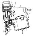
以下、本発明を図面に基づいて説明する。なお、図1はファスナー打機の全体の側面図、図2はマガジンを開放した状態の側面図であり、図3は連結ファスナーの装填時の側面図である。 Hereinafter, the present invention will be described with reference to the drawings. 1 is a side view of the entire fastener driving machine, FIG. 2 is a side view of a state where the magazine is opened, and FIG. 3 is a side view of when the connecting fastener is loaded.
図1において符号Aはファスナー打機を示す。ファスナー打機Aはボディ1の後部にグリップ2を、ボディ1の下部には射出口を有するノーズ部7をそれぞれ一体に設け、ノーズ部7の後部には射出口にファスナーを供給するマガジン6を連設したもので、ボディ1内には打撃機構が設けられ、グリップ2の後端から取り込んだ圧縮空気をボディ1とグリップ2の内部に貯留しておき、トリガ3を引き操作することにより、圧縮空気で打撃機構を作動させ、マガジン6からノーズ部7の内部に供給されたファスナーを打出すように構成されている。
In FIG. 1, symbol A indicates a fastener driving machine. The zipper A has a
なお、連結ファスナー5は多数のファスナーaをワイヤ11を介して連結したもので、コイル状に巻回されてマガジン6に収納されている。連結ファスナー5の先頭ファスナーは図示しないファスナー送り機構によりファスナー供給通路10を通って前方のノーズ部7の射出口9に順次供給される。ファスナー供給通路10はドア8によって開閉可能となっている。
Note that the connecting
次に、マガジン6は、主にマガジン本体4とネイルサポート12とガイドポスト13とから構成されている。
Next, the
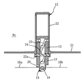
図2〜図4に示されるように、マガジン本体4は、マガジン主体4aとマガジンキャップ14とからなり、マガジン主体4aは、上底部15aと下底部16aと半円筒部17aとからなる有底半円筒状の形状をなしている。マガジンキャップ14も、上底部15bと下底部16bと半円筒部17bとからなる有底半円筒状の形状をなしている。マガジン主体4aの下底部16aには支軸18が設けられ、この支軸18にマガジンキャップ14が回動自在に支持されている。これにより、マガジンキャップ14を回動させることにより、マガジン本体4は中央から割れて大きく開口する。
2 to 4, the magazine
ガイドポスト13は円筒状で、マガジン本体4の中央部に配置され、マガジン主体4aの支軸18の中央部に回動自在に支持され、捩りコイルバネ19(図8参照)によりマガジン主体から離れる方向にマガジンキャップ14の下底部16aに対して垂直になるように付勢されている。ガイドポスト13の下部には、図5に示されるように、マガジンキャップ14の下底部16bに直角に係合するように係合片20が形成されている。
The
ネイルサポート12は、連結ファスナー5を載置する円形のサポート部材21の中央部にネイルポスト22を立設して成るもので、ネイルポスト22はガイドポスト13の外側に嵌合され、上下方向に沿ってスライド可能に支持されている。
The
マガジンキャップ14が閉じているときは、ガイドポスト13に支持されているネイルサポート12のサポート部材21の外周縁と、マガジンキャップ14の半円筒部17bの内壁と接触して垂直に起立している。また、マガジンキャップ14が開口方向に回動すると、ガイドポスト13も所定の角度まで支軸18ととともに回動する。つまり、図5の左側がマガジン主体側、右側がマガジンキャップ側であるが、ガイドポスト13は同図の右方向に倒れる。50〜60度ほど傾斜すると、支軸18の左下の三角形状の突起29の斜辺がマガジン主体の下底部16aに当り、傾斜が規制される。そこで、連結ファスナーをネイルサポート12に載せると、その重みでマガジン主体4aの方向に起き上がる。そのときに、ガイドポスト13の係合片20とマガジン主体4aの下底部16aが係合すると同時に、ネイルサポート12のサポート部材21の外周縁とマガジン主体4aの半円筒部17aの内壁と接触し、直立状態になる。マガジンキャップ14が閉じ方向に回動すると、マガジンキャップ14の下底部16bにガイドポスト13の係合片20が係合するので、ガイドポスト13も一体に回動し、マガジン主体4aの下底部16aに対して垂直に起立して連結ファスナー5を保持する。
When the
上記マガジン構成によれば、コイル状に巻きまわした連結ファスナー5をマガジン6に装填する場合、マガジン本体4のマガジンキャップ14を支軸18を中心に下方に回動してマガジン本体4を図2のように開放する。このときにネイルサポート12が傾くので、ネイルポスト22を連結ファスナー5の中心孔に挿入し、さらにマガジンキャップ14を上方向に回動して図1のように閉じればよい。
According to the above-described magazine configuration, when the connecting
ところで、ネイルサポート12はガイドポスト13のまわりに回転可能で、回転することによって、装填された連結ファスナー5のファスナーの長さに応じてマガジン本体4内における高さ位置を調整できるように構成されている。すなわち、図4及び図5に示されるように、ガイドポスト13には、互いに対向する壁部に、水平溝23aと傾斜溝23bとを交互に螺旋状に連続するガイド溝23が、水平溝23aと傾斜溝23bが互いに向き合うように貫通形成されている。傾斜溝23bは、ファスナーが消費されるに伴って連結ファスナー5が回転する先に設けられている。ファスナーが消費されると連結ファスナー5は上から見て右回転するので、傾斜溝23bは水平溝23aに向かって左側に形成されるようにする。
By the way, the
サポート部材21の下方にはネイルポスト22の延長部22aが形成され、延長部22aにはガイドピン24が嵌挿され、ガイドピン24はガイドポスト13の対向するガイド溝23を貫通している。
An
上記ネイルポスト22の支持機構によれば、ネイルサポート12を回転させると、ガイドピン24はガイド溝23に沿って摺動する。水平溝23aに沿って摺動するときはネイルサポート12の高さ位置は同じであるが、傾斜溝23bに沿って摺動すると、ガイド溝23とともにネイルサポート12も上方又は下方に移動しながら回転するからその高さ位置も変化する。上記実施形態では、4個の水平溝23aが90°間隔に形成されているから、ネイルサポート12の高さ位置を4段階に切り替え調整することができる。
According to the support mechanism for the
また、マガジン主体4aの内壁には図6に示すように、水平溝23aに対応する高さ位置を示す目盛25が刻印されている。これにより、ネイルサポート12がどの高さ位置にあるかを目視することができる。
Further, as shown in FIG. 6, a
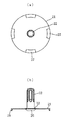
さらに、ネイルサポート12のサポート部材21の外周縁には、図7(b)に示されるように、等間隔に4個の高さ位置表示部26が下方に突出形成されている。これらの高さ位置表示部26は連結ファスナーのファスナーの軸長に適したサポート部材21の高さを示すもので、ガイドポスト13の水平溝23aが正面に対応するように位置決めするとともに、ガイドピン24の延長方向に4個中2個の高さ位置表示部26が対応するように形成するのが好ましい。
Further, as shown in FIG. 7B, four height
また、サポート部材21には高さの調整位置が表示されているので、連結ファスナー5を装填した後、連結ファスナー5が邪魔してマガジン主体4aの目盛25が見えないときでも、高さ位置表示部26を見てネイルサポート12を容易に所望の適正な高さ位置に調整することができる。しかも、扱いに慣れれば、図6に示されるように、連結ファスナー5のファスナー頭とマガジン主体4aの上底部15aとの間の間隔Hを見ることによっても、所定の高さ位置を感覚的に知ることができるので、特に目盛などを見なくても容易に調整操作することができる。
Since the height adjustment position is displayed on the
さらに、高さ位置表示部26はあるいはサポート部材21より下方に突出した部分の外面に設けられているので、連結ファスナーが直接に接触することがなく、磨耗しないので鮮明な表示を保つことができる。
Further, since the height
なお、高さ位置表示部26はサポート部材21の外周縁の端面かそれよりも下方の、連結ファスナーが接触しにくい部位に形成されていればよく、その形状は突起に限定されない。例えば、外周縁の端面に目印を付して表示する構成であってもよい。
In addition, the height
次に、サポート部材21の外周縁には、図7に示されるように、回転操作用の指当て部27が形成されている。この指当て部27は指が滑らないように、凹面部によって構成するか滑り止めを施すかするのが好ましい。これによれば、連結ファスナー5を装填した後に高さ位置を調整する際に指当て部27に指を当てて回すことができるので、確実に回転操作をすることができる。指当て部27を高さ位置表示部26に設けることにより、指の位置でネイルサポート12が調整位置にあるかどうかを知ることができる。
Next, on the outer peripheral edge of the
なお、指当て部27はサポート部材21の外周縁に限定されず、図7(b)に示されるように、ネイルポスト22に指当て部27aを形成してもよい。その形状も図示したものに限定されない。
Note that the
また、マガジンキャップ14はマガジン主体4aに対して横方向に回転して開閉するように構成することもできる。
The
次に、コイル状に巻き回した連結ファスナー5をマガジン6に装填する場合、上述のようにマガジンキャップ14を開くほかに、ノーズ部7のドア8を開き、マガジン本体4に収納した連結ファスナー5の先端側を引き出し、先頭のファスナーをノーズ部7の射出口9の内側に納めた後、ドア8とマガジンキャップ14を閉じる操作をしなければならないが、これを片手で簡単に操作できるようにするため、マガジンキャップ14の回動方向を次のように設定している。
Next, when the connecting
すなわち、図8に示されるように、マガジンキャップ14を回動可能に支持する支軸18は、連結ファスナー5の送り方向に対して一定の角度αをなすように設けられている。この角度αは、マガジンキャップ14が開き方向に回動するにつれてノーズ部7側に近づきながら傾くようにする角度であり、15°〜30°程度でよい。なお、図8はマガジン6の底面図である。
That is, as shown in FIG. 8, the
上記構成のマガジンキャップ14の開閉機構によって、コイル状に巻きまわした連結ファスナー5をマガジン6に装填する場合、まずノーズ部7のドア8を開いてファスナー供給通路を開放するとともに、マガジン本体4のマガジンキャップ14を支軸18を中心に図9のように下方に回動してマガジン本体4を開放する。このとき、マガジンキャップ14の支軸18は、連結ファスナー5の送り方向に対して一定の角度をなしているから、支軸が送り方向に設けられているものに比べ、図8の矢印のようにマガジンキャップ14が開き方向に回動するにつれて、その上底部15bはノーズ部7側(図の左側)に近づくように傾いていく。マガジンキャップ14はドア8にも近づいていく。そして、ネイルポスト22に連結ファスナー5の中心孔を挿入し、さらに連結ファスナー5をマガジン6の外側に引き出してファスナー供給通路に添わせつつ、その先頭ファスナーをノーズ部7の射出口9に収納する。その後、ドア8とマガジンキャップ14を閉じればよい。
When the connecting
ところで、ファスナー打機Aを片手(右利きの場合右手)に持ち、他方の手(左手)でファスナー打機Aの装填作業を行う場合、左手で図3のようにドア8とマガジンキャップ14を開き、連結ファスナー5をマガジン6内に収納し、さらに連結ファスナー5の一部を引き出して先頭ファスナーをノーズ部7の射出口9に収納する。その後、ドア8とマガジンキャップ14を閉じるときは、射出口9に収納した先頭ファスナーがワイヤの曲り癖によって外に飛び出さないように、図9に示されるように、左手の親指で連結ファスナー5の先端側をファスナー供給通路10に押し付けて保持し、薬指又は薬指と小指を開放状態にあるマガジンキャップ14の下底部16bの裏側に当て、手を握りこんでマガジンキャップ14を上側に持ち上げるようにすると、合成樹脂製で軽いマガジンキャップ14は支軸18を中心に回動して閉じ状態となる。このとき、閉じ状態に保持できる程度にすれば足りる。次に、マガジンキャップ14から指を離し、左手の親指で連結ファスナー5の先端側をファスナー供給通路に押し付けたまま、自由になった人差し指をノーズ部7側にまわし、人差し指でドア8を閉じる。マガジンキャップ14とドア8を閉めた後、両方を上からしっかりとロックすればよい。
By the way, when the zipper A is held in one hand (right hand if right-handed) and the zipper A is loaded with the other hand (left hand), the
なお、マガジンキャップ14の閉じ方は上述の例に限定されない。例えば、薬指や小指を使わずに、手首をマガジンキャップ14に当てて押し回すようにして閉じてもよい。
The method for closing the
上述のように、左手の親指で連結ファスナー5の先端側をファスナー供給通路に押し付けたまま、薬指又は薬指と小指をマガジンキャップ14の下底部16の裏側に当てる際、親指はノーズ部7の射出口9の近傍に当てなければならないので、マガジンキャップ14はできるだけノーズ部7に近い位置にあるのが好ましい。これに対応し、マガジンキャップ14は開き方向に回動するにつれてノーズ部7側に近づくように傾いていくから、閉じるときも薬指や小指をマガジンキャップ14に無理なく当てて容易確実に閉じ作動させることができる。
As described above, when the ring finger or the ring finger and the little finger are applied to the back side of the lower bottom portion 16 of the
なお、本発明は連結ファスナーのマガジンとファスナー打機に限定されない。打ち込みネジなどの連結ファスナーとその打ち込み工具などにも適用することができる。 In addition, this invention is not limited to the magazine of a connection fastener, and a fastener driving machine. The present invention can also be applied to a connecting fastener such as a driving screw and its driving tool.
1 ファスナー打機
6 マガジン
4 マガジン本体
4a マガジン主体
7 ノーズ部
12 ネイルサポート
13 ガイドポスト
14 マガジンキャップ
18 支軸
21 サポート部材
22 ネイルポスト
23 ガイド溝
23a 水平溝
23b 傾斜溝
24 ガイドピン
DESCRIPTION OF
Claims (3)
該マガジン主体の底部に回動自在に支持された有底半円筒状のマガジンキャップと、
を備え、
上記マガジンキャップは、上記マガジン主体の半円状の底部にその直径方向に設けられた支軸を中心に回動可能に設けられているとともに、上記支軸は底面視において上記連結ファスナーの送り方向に対して一定の角度をなし、上記マガジンキャップが開き方向に回動するにつれて上記ファスナーが打ち出されるノーズ部側に近づくように傾くことを特徴とする連結ファスナーのマガジン。 A magazine main body with a bottomed semi-cylindrical shape that houses a connected fastener wound in a coil shape by connecting a number of fasteners,
A bottomed semi-cylindrical magazine cap rotatably supported at the bottom of the magazine main body;
With
The magazine cap is provided on a semicircular bottom portion of the magazine main body so as to be rotatable about a support shaft provided in a diametrical direction thereof, and the support shaft is fed in the feeding direction of the connecting fastener in a bottom view. A magazine for a connected fastener, characterized in that the magazine cap is inclined so as to approach the nose portion side where the fastener is driven out as the magazine cap rotates in the opening direction.
上記ガイドポストは、上記マガジンキャップの開閉に伴って上記マガジン主体に対して傾斜することを特徴とする、請求項1記載の連結ファスナーのマガジン。 A guide post is erected on the center bottom of the magazine.
The guide post, and wherein the inclined with respect to the magazine main with the opening and closing of the magazine cap magazine connected fastener assembly according to claim 1, wherein.
Priority Applications (1)
| Application Number | Priority Date | Filing Date | Title |
|---|---|---|---|
| JP2012115337A JP5482825B2 (en) | 2012-05-21 | 2012-05-21 | Magazine for connecting fasteners and driving tool equipped with this magazine |
Applications Claiming Priority (1)
| Application Number | Priority Date | Filing Date | Title |
|---|---|---|---|
| JP2012115337A JP5482825B2 (en) | 2012-05-21 | 2012-05-21 | Magazine for connecting fasteners and driving tool equipped with this magazine |
Related Parent Applications (1)
| Application Number | Title | Priority Date | Filing Date |
|---|---|---|---|
| JP2009261713A Division JP5381635B2 (en) | 2009-11-17 | 2009-11-17 | Magazine for connecting fasteners and driving tool equipped with this magazine |
Publications (3)
| Publication Number | Publication Date |
|---|---|
| JP2012179710A JP2012179710A (en) | 2012-09-20 |
| JP2012179710A5 JP2012179710A5 (en) | 2012-12-06 |
| JP5482825B2 true JP5482825B2 (en) | 2014-05-07 |
Family
ID=47011378
Family Applications (1)
| Application Number | Title | Priority Date | Filing Date |
|---|---|---|---|
| JP2012115337A Active JP5482825B2 (en) | 2012-05-21 | 2012-05-21 | Magazine for connecting fasteners and driving tool equipped with this magazine |
Country Status (1)
| Country | Link |
|---|---|
| JP (1) | JP5482825B2 (en) |
Families Citing this family (1)
| Publication number | Priority date | Publication date | Assignee | Title |
|---|---|---|---|---|
| JP6136191B2 (en) * | 2012-10-25 | 2017-05-31 | マックス株式会社 | Connecting fastener magazine and driving tool |
Family Cites Families (2)
| Publication number | Priority date | Publication date | Assignee | Title |
|---|---|---|---|---|
| JPS5457682U (en) * | 1977-09-30 | 1979-04-20 | ||
| JP2550735Y2 (en) * | 1993-05-31 | 1997-10-15 | 兼松日産農林株式会社 | Magazine for fastener driving tools |
-
2012
- 2012-05-21 JP JP2012115337A patent/JP5482825B2/en active Active
Also Published As
| Publication number | Publication date |
|---|---|
| JP2012179710A (en) | 2012-09-20 |
Similar Documents
| Publication | Publication Date | Title |
|---|---|---|
| US7210578B2 (en) | Display unit for storing tool assembly | |
| TWM342924U (en) | Folding knife with trigger on knife handle | |
| US20150026899A1 (en) | Multi-Tool Wrench | |
| US9409289B2 (en) | System, method, and apparatus, for a handle attachment for a mobile device | |
| JP5482825B2 (en) | Magazine for connecting fasteners and driving tool equipped with this magazine | |
| JP5381635B2 (en) | Magazine for connecting fasteners and driving tool equipped with this magazine | |
| JP5998847B2 (en) | Nailer | |
| JP5482826B2 (en) | Magazine for connecting fasteners and driving tool equipped with this magazine | |
| JP2012179710A5 (en) | ||
| US20080296187A1 (en) | Tool bit caddy and method of operating the same | |
| US9134447B1 (en) | Magnetic stud finder with flexible member carrying multiple magnetic elements | |
| JP2012152899A5 (en) | ||
| US7841245B1 (en) | Electronic torque wrench | |
| JP6136191B2 (en) | Connecting fastener magazine and driving tool | |
| JP3151289U (en) | Suitcase carry bar handle structure | |
| JP5607983B2 (en) | compass | |
| JP2022106256A (en) | Tool holder | |
| JP2010053532A (en) | Agricultural work prop driving implement | |
| JP4254461B2 (en) | Nailing machine magazine for nailing machine | |
| JP4897601B2 (en) | Tool holder | |
| JP5994567B2 (en) | Pneumatic tool | |
| JP6777353B1 (en) | Golf club case | |
| US1212376A (en) | Line-reel. | |
| EP2590785B1 (en) | Magazine for a nailing tool | |
| JP2004351576A (en) | Magazine for storing nail for nailing machine |
Legal Events
| Date | Code | Title | Description |
|---|---|---|---|
| A521 | Written amendment |
Free format text: JAPANESE INTERMEDIATE CODE: A523 Effective date: 20121023 |
|
| A621 | Written request for application examination |
Free format text: JAPANESE INTERMEDIATE CODE: A621 Effective date: 20121023 |
|
| A977 | Report on retrieval |
Free format text: JAPANESE INTERMEDIATE CODE: A971007 Effective date: 20131017 |
|
| A131 | Notification of reasons for refusal |
Free format text: JAPANESE INTERMEDIATE CODE: A131 Effective date: 20131022 |
|
| A521 | Written amendment |
Free format text: JAPANESE INTERMEDIATE CODE: A523 Effective date: 20131220 |
|
| TRDD | Decision of grant or rejection written | ||
| A01 | Written decision to grant a patent or to grant a registration (utility model) |
Free format text: JAPANESE INTERMEDIATE CODE: A01 Effective date: 20140121 |
|
| A61 | First payment of annual fees (during grant procedure) |
Free format text: JAPANESE INTERMEDIATE CODE: A61 Effective date: 20140203 |
|
| R150 | Certificate of patent or registration of utility model |
Ref document number: 5482825 Country of ref document: JP Free format text: JAPANESE INTERMEDIATE CODE: R150 |