JP5481020B2 - Tire pressure monitoring method - Google Patents
Tire pressure monitoring method Download PDFInfo
- Publication number
- JP5481020B2 JP5481020B2 JP2007184060A JP2007184060A JP5481020B2 JP 5481020 B2 JP5481020 B2 JP 5481020B2 JP 2007184060 A JP2007184060 A JP 2007184060A JP 2007184060 A JP2007184060 A JP 2007184060A JP 5481020 B2 JP5481020 B2 JP 5481020B2
- Authority
- JP
- Japan
- Prior art keywords
- tire
- air pressure
- signal
- user
- error
- Prior art date
- Legal status (The legal status is an assumption and is not a legal conclusion. Google has not performed a legal analysis and makes no representation as to the accuracy of the status listed.)
- Expired - Fee Related
Links
Images

Classifications
-
- B—PERFORMING OPERATIONS; TRANSPORTING
- B60—VEHICLES IN GENERAL
- B60C—VEHICLE TYRES; TYRE INFLATION; TYRE CHANGING; CONNECTING VALVES TO INFLATABLE ELASTIC BODIES IN GENERAL; DEVICES OR ARRANGEMENTS RELATED TO TYRES
- B60C23/00—Devices for measuring, signalling, controlling, or distributing tyre pressure or temperature, specially adapted for mounting on vehicles; Arrangement of tyre inflating devices on vehicles, e.g. of pumps or of tanks; Tyre cooling arrangements
- B60C23/02—Signalling devices actuated by tyre pressure
- B60C23/04—Signalling devices actuated by tyre pressure mounted on the wheel or tyre
- B60C23/0408—Signalling devices actuated by tyre pressure mounted on the wheel or tyre transmitting the signals by non-mechanical means from the wheel or tyre to a vehicle body mounted receiver
-
- B—PERFORMING OPERATIONS; TRANSPORTING
- B60—VEHICLES IN GENERAL
- B60C—VEHICLE TYRES; TYRE INFLATION; TYRE CHANGING; CONNECTING VALVES TO INFLATABLE ELASTIC BODIES IN GENERAL; DEVICES OR ARRANGEMENTS RELATED TO TYRES
- B60C23/00—Devices for measuring, signalling, controlling, or distributing tyre pressure or temperature, specially adapted for mounting on vehicles; Arrangement of tyre inflating devices on vehicles, e.g. of pumps or of tanks; Tyre cooling arrangements
- B60C23/02—Signalling devices actuated by tyre pressure
- B60C23/04—Signalling devices actuated by tyre pressure mounted on the wheel or tyre
- B60C23/0401—Signalling devices actuated by tyre pressure mounted on the wheel or tyre characterised by the type of alarm
Description
本発明は一般的にはタイヤの監視・警告方法に関し、より詳細にはタイヤキャビティ空気圧に対応したタイヤ空気圧監視方法に関する。 The present invention generally relates to a tire monitoring / warning method, and more particularly to a tire pressure monitoring method corresponding to tire cavity air pressure.
タイヤの空気圧を正しく維持するとハンドリング性能が改善され、燃費効率が向上し、また車のタイヤの耐用年数が伸びることは十分証明されている。さらにタイヤの空気圧を正しく維持することは車の安全運転にとって重要な考慮事項である。このことは反駁を許さないほど重要であるにもかかわらず、一般のドライバの多くはタイヤ空気圧の監視や保守を十分頻繁に行なっているとは言えないであろう。またたとえ保守を十分に行なったタイヤであっても、破損が継続した後に車を運転していると空気圧が低下し、ドライバにとって潜在的に危険な状況となることがある。さらに「エキステンデッド・モビリテイ・タイヤ」(EMT)が登場して、ますます市場に広がるようになると、車のドライバにとって空気圧の低下や空気漏れを検出して、適切な処置を取ることが困難となることがある。その結果、製造者の推奨限度より低い空気圧でタイヤを長期間使用することにもなる。
複数のタイヤ空気圧監視システムが開発されてはいるが、その使用は限られたものである。一般的にこうしたシステムは、内部の空気圧と温度をリアルタイムに監視するセンサーをタイヤに搭載している。その情報は無線周波数(RF)を用いて無線でドライバに送信され、車の運転室に表示されるようになっている。この遠隔検出モジュールは、たとえば空気圧センサーおよび/または温度センサーのようなタイヤ状態モニター、信号処理装置、およびRF送信器によって構成されている。こうしたシステムはバッテリー給電式となっているか、さもなければ検出モジュールが「受動的」になっている。すなわち電子制御ユニット(「ECU」)に接続された遠隔送信器との電磁結合を通じて検出モジュールに給電している。このECUはタイヤ空気圧監視専用となっているか、あるいは車の他の機能と共有されている。たとえばECUはダッシュボード・コントローラやその他のオンボード・コンピュータとなる場合がある。こうしたタイヤ監視システムの事例については、本出願の譲受人が所有する米国特許第6,868,358号および第6,591,671号に詳述されている。なおこれらの特許についてはその全てをここに取り込んでいる。
タイヤ監視システムの目的は、1本またはそれ以上のタイヤに空気圧異常が発生した場合、ドライバにそのことを警告することにある。一般的にはタイヤの空気圧と温度が報告されるパラメータとなっている。その情報を役立てるためには、情報を迅速に伝達すると共に、情報には信頼性がなくてはならない。さらに、タイヤの空気圧情報を表示するだけでは、ユーザーが状況を改善する上で役立たない。したがって、タイヤ空気圧の異常を表示するのみならず、ユーザーがこうした異常を十分に解消するのを支援するようなタイヤ監視システムが必要となる。
Proper maintenance of tire pressure has been proven to improve handling performance, improve fuel efficiency, and increase the useful life of car tires. In addition, maintaining the correct tire pressure is an important consideration for safe driving. Although this is unimportantly important, many common drivers may not be able to monitor and maintain tire pressures often enough. Even if the tire has been sufficiently maintained, if the car is driven after the damage continues, the air pressure may drop, which may be a potentially dangerous situation for the driver. In addition, as “Extended Mobility Tires” (EMT) have emerged and become increasingly popular in the market, it is difficult for car drivers to detect low pressures and air leaks and take appropriate measures. It may become. As a result, tires can be used for a long time at a lower air pressure than the manufacturer's recommended limit.
Although multiple tire pressure monitoring systems have been developed, their use is limited. In general, such systems have sensors on tires that monitor the internal air pressure and temperature in real time. The information is transmitted wirelessly to the driver using radio frequency (RF) and displayed in the car cab. The remote detection module is constituted by a tire condition monitor such as a pneumatic sensor and / or a temperature sensor, a signal processing device, and an RF transmitter. These systems are battery powered or the detection module is “passive”. That is, the detection module is powered through electromagnetic coupling with a remote transmitter connected to an electronic control unit (“ECU”). This ECU is dedicated to tire pressure monitoring or shared with other functions of the car. For example, the ECU may be a dashboard controller or other on-board computer. Examples of such tire monitoring systems are detailed in US Pat. Nos. 6,868,358 and 6,591,671 owned by the assignee of the present application. All of these patents are incorporated here.
The purpose of the tire monitoring system is to alert the driver when an abnormal air pressure occurs in one or more tires. Generally, the tire pressure and temperature are reported parameters. In order to make use of the information, the information must be transmitted quickly and the information must be reliable. Furthermore, simply displaying tire pressure information does not help the user improve the situation. Therefore, there is a need for a tire monitoring system that not only displays abnormalities in tire pressure, but also assists the user to sufficiently resolve such abnormalities.
本発明は、不適切なタイヤ空気圧について警告するのみならず、ユーザーにとって適切なタイヤ空気圧が得やすくなる、単純にしてかつ統合化したタイヤ空気圧監視システムを提供する。
本発明は、その原理および記述された実施態様によって、車の各タイヤの空気圧を監視する方法を提供する。車は、その制御装置に各タイヤの空気圧を示す信号を供給するタイヤ空気圧監視装置を有している。車の制御装置はユーザーI/Oを有している。そしてこの方法では、最初にいずれかのタイヤの空気圧エラーを検出し、次いで当該タイヤの空気圧エラーを示す1番目の感覚認知信号をユーザーに提供する。次いで、予想されるタイヤの空気入れ作業を示すユーザー入力が検出される。その後、当該タイヤの空気圧が所定のタイヤ空気圧にほぼ等しくなると、それに対応して2番目の感覚認知信号がユーザーに提供される。このようにして、この方法では、タイヤ空気圧エラーを表示した後、タイヤの空気入れの適切な時期をユーザーが決めるのを支援する。
本発明の1つの様相では、1番目の感覚認知信号は視覚表示であり、ユーザー入力は視覚表示にある入力ボタンである。また2番目の感覚認知信号は視覚表示または聴覚信号である。
別の実施態様によると、この方法では1番目のタイヤの空気圧の変化を検出し、そのタイヤが当該タイヤとほぼ同一であるか否かを決める。そして1番目のタイヤが当該タイヤとは異なっていると、それに対応して3番目の感覚認知信号がユーザーに提供される。本発明の1つの様相では、3番目の感覚認知信号は視覚表示または聴覚信号である。
本発明のこれらのおよびその他の目的と利点は、以下の図面と共に次の詳細説明を読むとより明らかになるであろう。
The present invention provides a simple and integrated tire pressure monitoring system that not only warns about inadequate tire pressure, but also makes it easier for the user to obtain the proper tire pressure.
The present invention, in accordance with its principles and described embodiments, provides a method for monitoring the air pressure of each tire of a vehicle. The vehicle has a tire air pressure monitoring device that supplies a signal indicating the air pressure of each tire to the control device. The vehicle control device has user I / O. In this method, first, a tire pressure error is detected, and then a first sensory recognition signal indicating the tire pressure error is provided to the user. A user input is then detected indicating an expected tire filling operation. Thereafter, when the tire pressure becomes substantially equal to a predetermined tire pressure, a second sensory recognition signal is provided to the user correspondingly. In this way, the method assists the user in determining an appropriate time for inflating the tire after displaying the tire pressure error.
In one aspect of the invention, the first sensory perception signal is a visual display and the user input is an input button on the visual display. The second sensory recognition signal is a visual display or an auditory signal.
According to another embodiment, the method detects a change in air pressure of the first tire and determines whether the tire is substantially identical to the tire. If the first tire is different from the tire, a third sensory recognition signal is provided to the user correspondingly. In one aspect of the invention, the third sensory perception signal is a visual display or an auditory signal.
These and other objects and advantages of the present invention will become more apparent upon reading the following detailed description in conjunction with the following drawings.
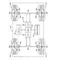
図1を参照すると、タイヤ状態監視・制御システム20が搭載されているのは、ファントム表示した車22、たとえばそれぞれ4個のホイール(図示されていない)に取り付けた4本の空気タイヤ24a、24b、24cおよび24dを有する乗用車である。車22には、たとえばRS−485のような両方向性多重化シリアルデータバス26およびLAN、またはツイストペアの絶縁線で構成することがある同等のデータバスが装備されている。シリアルデータバス26はECU28の内部にあるシリアルデータバス・インタフェース30に接続されている。このECUは、たとえば車搭載型コンピュータ、インダッシュ・コントローラまたは同等のコンピュータやコントローラとなる場合がある。なおこのECUは、たとえばインダッシュ・タッチスクリーン、LCDスクリーンまたは同等の表示部のような表示ユニット32を有しており、そのユニットは図示したようにECU28に直接接続されているか、それともシリアルデータバス26を経由してECU28に間接的に接続されている。車にデータバスが装備されていない場合、車にデータバスを追加することがあるが、それも本発明の範囲内である。たとえば車に既存のデータバスが無い場合、この用途に適した既知のシリアル通信基準に従って専用のデータバスを装備することがある。
4本のタイヤ24a−24dには、それぞれ既知の電子モジュール(「タグ」)34a−34dと、各タイヤの空気圧および/または空気温度のような1つまたは2つ以上の状態を監視することができる、それぞれ既知のタイヤ状態センサー33a−33dが装備されている。各タグは、車の各タイヤ内部について監視した1つまたは2つ以上の状態を示す無線周波数(RF)信号か、またはその関数として変調した無線周波数(RF)信号を送信するように働く。1つの実施例では、タグ34a−34dは無線周波数特定タグに用いるようなトランスポンダであるが、代替として1つまたは2つ以上の状態センサーと無線周波数送信器のみで構成することもある。
システム20はまた、各タイヤ24a−24dに関連した4個の既知のモニターまたは呼出しユニット36a−36dを有しており、かつそれらのユニットは、たとえば既知の方法で車22のそれぞれのホイールウェルに取り付けるなど、各タイヤに近接して配置することが好ましい。モニター36a−36dは電源(図示されていない)に接続されており、またECU28と個別通信を行なうためシリアルデータバス26にも接続されている。モニター36a−36dは、各タグ34a−34dに信号を送信し、またそこから信号を受信するためのそれぞれのアンテナ38a−38dと、それぞれの送信器/受信器(図示されていない)とを有している。モニター36a−36dは、たとえば米国カリフォルニア州サンタクララのナショナル・セミコンダクタ社が市販しているDS36277型ドミナントモード・マルチポイント・トランシーバーのような、データトランシーバーを用いて実現することができる。
各タグに向けたモニターの送信信号には受動タグを活性化するキャリア信号が含まれることがあり、また低パワーのスリープモードにある能動タグに対する「起動」信号が含まれることもある。各アンテナ38a−38dを含むモニター36a−36dの全ての構成要素を単一のパッケージに封入することができるが、これも本発明の範囲内である。また代替として、アンテナをこうしたパッケージの外部に配置することもできる。
タグ34a−34dのRF信号によって搬送されたタイヤの監視状態データは、たとえば復調するなど、解読してECU28に供給し、タッチスクリーン表示32を経由してユーザーに提供することができる。既知の方法によれば、タッチスクリーン32を経由して視覚の警告や警報をユーザーに提供することができる。また別の既知の実施形態によれば、ECU28によって聴覚の警告や警報をユーザーに提供し、聴覚信号発生装置40を作動させることができる。この聴覚信号は合成音声メッセージおよび/またはビープ音、チャイム、ブザーあるいはさまざまな長さや周波数を有するその他の音またはその他の聴覚信号の形態を取ることがある。たとえば聴覚や視覚による警告や警報のような感覚認知信号の正確な形態は、車の製造者によって決められることが多い。さらに車の制御には、「スマート」サスペンションシステムに関連入力を供給するなどタイヤの動的状態に関する情報を利用することがある。
図2は、インダッシュ・タッチスクリーン32を用いて実現することができるタイヤ情報表示に関する多数の代替構成案の1つを示したものである。4本の垂直バー44、46、48および50からなるアレー表示を用いて、図1に示す車22の4本の各タイヤ24a−24dを表すことができる。そしてアイコン52、54および56を採用して、タイヤ空気圧に関する良好、要注意および不可の各範囲を指示することができる。タイヤ空気圧を表しているアイコン52−56の表示は、垂直バー44−50で示してある。アイコンと関連した表示の選択は車の製造者によって変わることがある。外気温度もまた58に示すように表示することがある。
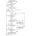
図1のタイヤ空気圧監視システム20を利用する方法を、ECU28または同等のコンピュータを用いて実行するタイヤ空気圧サイクルプログラムすなわちサブルーチン302として図3に示す。ECU28は最初304において、タイヤ状態モニター33a−33dのいずれかが、いずれかのタイヤの空気圧エラーを検出したか否かを既知の方法で確定する。次いでタイヤ空気圧エラーは306において、図2に示すものに類似した表示構成のタッチスクリーン32を用いて表示される。表示44−50のいずれかが、表示46および48に示すように空気圧要注意および空気圧不可を表示すると、ECU28はフィルリクエスト・プッシュボタン60をタッチスクリーン32に表示する。この実施例では、タイヤ24a−24dのいずれかの空気圧を変更する前にユーザーがフィルリクエスト・プッシュボタン60を作動する。フィルリクエスト・プッシュボタン60が作動すると、308においてECU28がそのことを検出する。フィルリクエスト・プッシュボタン60が可視状態となるのは、車22が停止しており、かつ駐車位置にあることをECU28が検出した場合か、さらに、車22が駐車位置にある間に燃料供給作業が検出された場合のみである。後者の場合にフィルリクエスト・プッシュボタン60が可視状態となるのは、燃料供給ドアが開いていることをECU28が検出した場合のみである。
ECU28はその後310において各タイヤ24a−24dの空気圧を監視し、これらタイヤのいずれかの空気圧が変化したか否かを検出する。タイヤ空気圧の変化が検出されると、ECU28は312において、空気圧が変化しているタイヤが空気圧の調整を必要としているタイヤの1つ、たとえば表示46および48のそれぞれが示すタイヤ24bまたは24cであるかどうかを決定する。またたとえば表示44および50に示すように、空気圧が良好なタイヤ24aまたは24dのようなその他のタイヤのいずれかの空気圧が変化している場合、ECU28は314において誤タイヤ警報信号を発生する。こうした信号は、聴覚信号発生装置40による聴覚警報や、たとえば表示44、50の色を変えるか、または表示44、50を点滅させて生成する表示32上の視覚警報の双方、またはいずれかとなることがある。
もしECU28が312において、変化しているタイヤ空気圧が、たとえばタイヤ24bまたは24cのように空気圧エラーのあるタイヤに対応していると決定した場合、ECU28は316において、タイヤ空気圧の変化が良好なレベルに到達するまで監視を継続する。そして良好なレベルに到達すると、ECU28は318において、良好アイコン52が表示32に示す正しい空気圧信号を出力する。さらに良好なタイヤ空気圧のレベルに到達すると、表示46、48は、べた一色のまたは点滅する緑色に切り替わることがある。さらに聴覚信号発生装置40によって良好なタイヤ空気圧を示す聴覚信号が生成されることがある。するとECU28は320において、全てのタイヤの空気圧が良好であるか否かを確定する。そしてタイヤ空気圧エラーがまだ存続している場合、ステップ304−320に関連して説明した方法を反復する。ECU28が24a−24dの全タイヤの空気圧が良好な状態にあることを確定すると、ECU28は322において、適切な視覚表示および/または聴覚信号を発生する。
本発明についてさまざまな実施形態の記述をもとに説明し、またこれら実施形態についてもかなり詳細に記述してきたが、添付した特許請求の範囲をこうした詳細内容に制限したり、またいかなる方法においても限定したりすることは出願者の意図するところではない。当業者には、直ちにさらなる利点や修正が明らかとなるであろう。したがって最も広範囲にわたる様相のもとにある本発明は、図示し、また説明した特定の詳細内容に限定されるものではない。そのため、ここに記述した詳細内容から外れることがあっても、それは以下の特許請求の精神および範囲を逸脱するものではない。
Referring to FIG. 1, the tire condition monitoring /
Each of the four
The
The monitor transmit signal for each tag may include a carrier signal that activates the passive tag, and may also include a “wakeup” signal for the active tag in a low power sleep mode. All components of the
The tire monitoring status data conveyed by the RF signals of the tags 34 a-34 d can be decoded and supplied to the
FIG. 2 illustrates one of many alternative configurations for tire information display that can be implemented using the in-
A method utilizing the tire
Thereafter, the
If the
While the invention has been described in terms of various embodiments, and has been described in considerable detail, the appended claims are limited to such details or in any manner. It is not the intention of the applicant to limit. Further advantages and modifications will immediately become apparent to those skilled in the art. Accordingly, the invention in its broadest aspects is not limited to the specific details shown and described. Thus, departures from the details described herein do not depart from the spirit and scope of the following claims.
20 タイヤ状態監視・制御システム
22 車
24a−24d 空気タイヤ
26 両方向性多重化シリアルデータバス
28 ECU
30 シリアルデータバス・インタフェース
32 インダッシュ・タッチスクリーン、LCDスクリーンまたは同等の表示部のような表示ユニット
33a−33d タイヤ状態センサー
34a−34d 電子モジュール(タグ)
36a−36d モニターまたは呼出しユニット
40 聴覚信号発生装置
44、46、48、50 垂直バーからなるアレー表示
52 アイコン(空気圧良好)
54 アイコン(空気圧要注意)
56 アイコン(空気圧不可)
58 外気温度表示
60 フィルリクエスト・プッシュボタン
20 Tire Condition Monitoring /
30 Serial
36a-36d Monitor or calling
54 icon (pneumatic pressure caution)
56 icon (no air pressure)
58
Claims (12)
いずれか1つのタイヤのタイヤ空気圧エラーを検出することと、
前記のいずれか1つのタイヤの前記タイヤ空気圧エラーを示し、視覚表示を含む第1の感覚認知信号をユーザーに提供することと、
次いで、予想されるタイヤ空気入れ作業を示すユーザー入力を検出することと、
次いで、前記タイヤ空気入れ作業が行われた第1のタイヤの空気圧の変化を検出することと、
前記第1のタイヤが、前記タイヤ空気圧エラーが検出された前記のいずれか1つのタイヤであるかどうかを判定することと、
前記第1のタイヤが、前記タイヤ空気圧エラーが検出された前記のいずれか1つのタイヤとは異なっていることに応答して第2の感覚認知信号を前記ユーザーに提供することと、
次いで、前記タイヤ空気圧エラーが検出された前記のいずれか1つのタイヤの空気圧が所定のタイヤ空気圧にほぼ等しくなったことに応答して第3の感覚認知信号を前記ユーザーに提供することと、
を有する、車の各タイヤの空気圧を監視する方法。 A method for monitoring the air pressure of each tire of a vehicle, comprising a tire air pressure monitoring device that outputs a signal indicating the air pressure of each tire to a vehicle control device, the vehicle control device having a user I / O Because
Detecting a tire pressure error in any one tire;
Providing the user with a first sensory perception signal indicating the tire pressure error of any one of the tires and including a visual indication;
Then detecting user input indicative of an expected tire filling operation;
Next, detecting a change in air pressure of the first tire that has been subjected to the tire inflation operation;
Determining whether the first tire is any one of the tires in which the tire pressure error is detected ;
Providing the user with a second sensory recognition signal in response to the first tire being different from any one of the tires in which the tire pressure error is detected ;
Then providing a third sensory recognition signal to the user in response to the air pressure of any one of the tires in which the tire air pressure error is detected being substantially equal to a predetermined tire air pressure;
A method for monitoring the air pressure of each tire of a vehicle.
前記車の制御装置によって前記ユーザーI/Oを作動させ、空気圧エラーを有する少なくとも1つのタイヤを特定し、視覚表示を含むタイヤ空気圧エラー信号を出力することと、
次いで、前記車の制御装置によって前記ユーザーI/Oを監視し、予想されるタイヤ空気入れ作業を示すユーザー入力を検出することと、
前記車の制御装置によって、前記タイヤ空気入れ作業が行われた第1のタイヤのタイヤ空気圧の変化を求めることと、
前記車の制御装置によって前記第1のタイヤが前記空気圧エラーを有する前記タイヤとして特定された前記の少なくとも1つのタイヤであるかどうかを判定することと、
前記車の制御装置によって前記ユーザーI/Oを作動させ、前記第1のタイヤが前記空気圧エラーを有する前記タイヤとして特定された前記の少なくとも1つのタイヤとは異なっていることに応答して誤タイヤ信号を出力すること、
次いで、前記車の制御装置によって前記ユーザーI/Oを作動させ、前記空気圧エラーを有する前記タイヤとして特定された前記の少なくとも1つのタイヤの空気圧が所定のタイヤ空気圧にほぼ等しくなったことに応答してタイヤ充満信号を供給すること、
を有する、車の各タイヤの空気圧を監視する方法。 A method of monitoring the air pressure of each tire of a vehicle, comprising a tire air pressure monitoring device for supplying a signal indicating the air pressure of each tire to a vehicle control device, the vehicle control device having a user I / O Because
Activating the user I / O by the vehicle controller to identify at least one tire having a pneumatic error and outputting a tire pneumatic error signal including a visual indication;
Then monitoring the user I / O by the vehicle controller and detecting a user input indicating an anticipated tire filling operation;
Determining a change in tire air pressure of the first tire on which the tire filling operation has been performed by the vehicle control device;
Determining whether the first tire is the at least one tire identified as the tire having the air pressure error by the vehicle control device;
Incorrect tire in response to actuating said user I / O by said vehicle control device and said first tire being different from said at least one tire identified as said tire having said air pressure error Outputting a signal,
Then, the user I / O is actuated by the vehicle control device in response to the air pressure of the at least one tire identified as the tire having the air pressure error being substantially equal to a predetermined tire air pressure. Supplying tire filling signal,
A method for monitoring the air pressure of each tire of a vehicle.
少なくとも1つのタイヤのタイヤ空気圧エラーの存在を求めることと、
求められた前記タイヤ空気圧エラーに応答して前記の少なくとも1つのタイヤを特定し、視覚表示によって示されるタイヤ空気圧エラー信号を発生することと、
次いで、タイヤ空気入れ作業を示すユーザー入力を検出することと、
前記タイヤ空気入れ作業が行われた第1のタイヤのタイヤ空気圧の変化を求めることと、
前記第1のタイヤが、前記タイヤ空気圧エラーの存在が求められた前記の少なくとも1つのタイヤであるかどうかを判定することと、
前記第1のタイヤが、前記タイヤ空気圧エラーの存在が認められた前記の少なくとも1つのタイヤとは異なっていることに応答して誤タイヤ信号を発生すること、
次いで、前記タイヤ空気圧エラーの存在が求められた前記の少なくとも1つのタイヤの空気圧がタイヤ充満空気圧にほぼ等しくなったことに応答してタイヤ充満信号を発生すること、
を有する、車の各タイヤの空気圧を監視する方法。 A method of monitoring the pressure of a car tire,
Determining the presence of a tire pressure error in at least one tire;
Identifying the at least one tire in response to the determined tire pressure error and generating a tire pressure error signal indicated by a visual display;
Then detecting user input indicating a tire filling operation;
Determining a change in tire air pressure of the first tire in which the tire inflation operation has been performed ;
And said first tire, to determine whether the presence of the tire pressure error is at least one tire of the obtained,
Generating a false tire signal in response to the first tire being different from the at least one tire in which the presence of the tire pressure error is observed ;
Generating a tire full signal in response to the air pressure of the at least one tire determined to be present of the tire air pressure error approximately equal to the tire full air pressure;
A method for monitoring the air pressure of each tire of a vehicle.
Applications Claiming Priority (2)
| Application Number | Priority Date | Filing Date | Title |
|---|---|---|---|
| US11/457,562 US7528705B2 (en) | 2006-07-14 | 2006-07-14 | Tire pressure monitoring method |
| US11/457,562 | 2006-07-14 |
Publications (3)
| Publication Number | Publication Date |
|---|---|
| JP2008018937A JP2008018937A (en) | 2008-01-31 |
| JP2008018937A5 JP2008018937A5 (en) | 2010-06-24 |
| JP5481020B2 true JP5481020B2 (en) | 2014-04-23 |
Family
ID=38626693
Family Applications (1)
| Application Number | Title | Priority Date | Filing Date |
|---|---|---|---|
| JP2007184060A Expired - Fee Related JP5481020B2 (en) | 2006-07-14 | 2007-07-13 | Tire pressure monitoring method |
Country Status (3)
| Country | Link |
|---|---|
| US (1) | US7528705B2 (en) |
| EP (1) | EP1878595B1 (en) |
| JP (1) | JP5481020B2 (en) |
Families Citing this family (17)
| Publication number | Priority date | Publication date | Assignee | Title |
|---|---|---|---|---|
| JP5540426B2 (en) * | 2009-06-26 | 2014-07-02 | 横浜ゴム株式会社 | Tire condition monitoring system |
| DE102009058881A1 (en) | 2009-12-18 | 2011-06-22 | Continental Automotive GmbH, 30165 | Filling and filling assistant |
| US20110202229A1 (en) * | 2010-02-18 | 2011-08-18 | General Motors Llc | In-vehicle tire gauge system and methods |
| US8564428B2 (en) | 2010-06-15 | 2013-10-22 | Honda Motor Co., Ltd. | Memorizing location of tires in TPMS and smart entry system |
| DE102010042432A1 (en) * | 2010-10-14 | 2012-04-19 | Robert Bosch Gmbh | Device and method for signaling functional failures of a vehicle |
| JP2012224159A (en) * | 2011-04-18 | 2012-11-15 | Tokai Rika Co Ltd | Tire air pressure monitoring system |
| JP6034576B2 (en) * | 2012-03-12 | 2016-11-30 | 矢崎総業株式会社 | Vehicle display device |
| US9120357B2 (en) * | 2013-03-15 | 2015-09-01 | Continental Automotive Systems, Inc. | Methods, systems and devices for integration of tire pressure monitoring sensors with a tire pressure monitoring system |
| GB201315427D0 (en) * | 2013-08-29 | 2013-10-16 | Agco Int Gmbh | Tyre pressure measurement on a vehicle |
| KR20170093238A (en) | 2014-12-16 | 2017-08-14 | 티알더블유 오토모티브 유.에스. 엘엘씨 | Tire fill assist method and apparatus |
| TWI651217B (en) * | 2016-11-10 | 2019-02-21 | 系統電子工業股份有限公司 | Buffer temporary storage device for vehicle tire pressure warning device and system thereof |
| DE102016225496A1 (en) * | 2016-12-19 | 2018-06-21 | Continental Automotive Gmbh | Electronic wheel unit and control device for a wheel monitoring system of a vehicle, wheel monitoring system for a vehicle and method for wheel monitoring in a vehicle |
| MX2021000652A (en) * | 2018-07-19 | 2021-03-25 | Nissan North America Inc | Vehicle tire pressure monitoring system. |
| US11273801B2 (en) | 2018-12-18 | 2022-03-15 | The Goodyear Tire & Rubber Company | Control system for an air maintenance tire system |
| GB2584851A (en) * | 2019-06-17 | 2020-12-23 | Airbus Operations Ltd | Indicating errors in a tyre monitoring system |
| US11377105B2 (en) * | 2019-08-13 | 2022-07-05 | Nissan North America, Inc. | Off-road vehicle speed control assembly |
| US11673434B2 (en) * | 2020-07-31 | 2023-06-13 | Rivian Ip Holdings, Llc | External vehicle tire pressure signaling |
Family Cites Families (16)
| Publication number | Priority date | Publication date | Assignee | Title |
|---|---|---|---|---|
| US5218861A (en) * | 1991-03-27 | 1993-06-15 | The Goodyear Tire & Rubber Company | Pneumatic tire having an integrated circuit transponder and pressure transducer |
| US5293919A (en) * | 1991-11-18 | 1994-03-15 | Hughes Aircraft Company | Self-regulating tire pressure system and method |
| US5500065A (en) * | 1994-06-03 | 1996-03-19 | Bridgestone/Firestone, Inc. | Method for embedding a monitoring device within a tire during manufacture |
| US6124647A (en) * | 1998-12-16 | 2000-09-26 | Donnelly Corporation | Information display in a rearview mirror |
| US6294989B1 (en) * | 1998-12-16 | 2001-09-25 | Donnelly Corporation | Tire inflation assistance monitoring system |
| US6445287B1 (en) * | 2000-02-28 | 2002-09-03 | Donnelly Corporation | Tire inflation assistance monitoring system |
| US6591671B2 (en) * | 1999-08-16 | 2003-07-15 | The Goodyear Tire & Rubber Company | Monitoring pneumatic tire conditions |
| US6255940B1 (en) * | 1999-10-01 | 2001-07-03 | The Goodyear Tire & Rubber Company | Apparatus for monitoring a condition of a tire |
| EP1263626A2 (en) * | 2000-03-02 | 2002-12-11 | Donnelly Corporation | Video mirror systems incorporating an accessory module |
| US6647773B2 (en) * | 2002-03-01 | 2003-11-18 | Lear Corporation | System and method for integrated tire pressure monitoring and passive entry |
| JP3931693B2 (en) * | 2002-03-13 | 2007-06-20 | マツダ株式会社 | Vehicle air pressure warning device |
| US6868358B2 (en) * | 2002-07-24 | 2005-03-15 | The Goodyear Tire & Rubber Company | Method for processing information in a tire pressure monitoring system |
| JP2004168185A (en) | 2002-11-20 | 2004-06-17 | Honda Motor Co Ltd | Tire air pressure monitoring device |
| JP3976271B2 (en) * | 2004-01-27 | 2007-09-12 | 本田技研工業株式会社 | Tire pressure monitoring device |
| JP2005212620A (en) * | 2004-01-29 | 2005-08-11 | Honda Motor Co Ltd | Tire air pressure monitoring device |
| US7323975B2 (en) * | 2005-04-19 | 2008-01-29 | General Motors Corporation | Tire pressure monitoring system and method therefor |
-
2006
- 2006-07-14 US US11/457,562 patent/US7528705B2/en not_active Expired - Fee Related
-
2007
- 2007-07-13 EP EP07013804A patent/EP1878595B1/en not_active Expired - Fee Related
- 2007-07-13 JP JP2007184060A patent/JP5481020B2/en not_active Expired - Fee Related
Also Published As
| Publication number | Publication date |
|---|---|
| EP1878595A2 (en) | 2008-01-16 |
| EP1878595A3 (en) | 2011-11-09 |
| EP1878595B1 (en) | 2013-01-02 |
| JP2008018937A (en) | 2008-01-31 |
| US7528705B2 (en) | 2009-05-05 |
| US20080018444A1 (en) | 2008-01-24 |
Similar Documents
| Publication | Publication Date | Title |
|---|---|---|
| JP5481020B2 (en) | Tire pressure monitoring method | |
| CN101391563B (en) | Tire inflation pressure detecting apparatus | |
| JP6331679B2 (en) | Tire pressure detector | |
| JP4412361B2 (en) | Wheel position detecting device, tire air pressure detecting device and transmitter / receiver provided with the same | |
| EP1452350A1 (en) | Method for allocating the positions of the tyres in a tyre monitoring system | |
| US20050270148A1 (en) | Trailer tire monitoring system and method | |
| KR20080026048A (en) | Wheel position detecting device and tire air pressure detecting device using the same | |
| US8674821B2 (en) | Tire pressure monitoring apparatus | |
| US8667837B2 (en) | Wireless tire pressure sensing device, method for setting a standard tire pressure thereof, and wireless tire pressure sensing activation device | |
| JP2003175711A (en) | Tire state monitoring device | |
| WO2012160780A1 (en) | Tire pressure detection device | |
| US20040193340A1 (en) | Tire status monitoring apparatus | |
| CN201863655U (en) | Tire pressure detection system | |
| US6999861B2 (en) | Tire status monitoring apparatus and receiver therefor | |
| JP2013043543A (en) | Valve id registration system | |
| JP2004299534A (en) | Tire air pressure monitoring system | |
| US8026803B2 (en) | Apparatus and process for monitoring a vehicle condition | |
| KR100949028B1 (en) | Tire pressure monitoring system for recognizing positions of tires automatically and operation method of the same | |
| WO2018029944A1 (en) | Tire-pressure monitoring system | |
| KR200274178Y1 (en) | Tire status warning apparatus | |
| JP7124416B2 (en) | Sensor ID registration system | |
| JP5459625B2 (en) | Tire information detection device | |
| US9457625B2 (en) | Tire pressure management system with enhanced wireless security and control method thereof | |
| JP2005162118A (en) | Tire pneumatic pressure monitor | |
| JP2003220809A (en) | Device for detecting tire mounting position |
Legal Events
| Date | Code | Title | Description |
|---|---|---|---|
| A521 | Written amendment |
Free format text: JAPANESE INTERMEDIATE CODE: A523 Effective date: 20100512 |
|
| A621 | Written request for application examination |
Free format text: JAPANESE INTERMEDIATE CODE: A621 Effective date: 20100512 |
|
| A131 | Notification of reasons for refusal |
Free format text: JAPANESE INTERMEDIATE CODE: A131 Effective date: 20120911 |
|
| A521 | Written amendment |
Free format text: JAPANESE INTERMEDIATE CODE: A523 Effective date: 20121121 |
|
| A131 | Notification of reasons for refusal |
Free format text: JAPANESE INTERMEDIATE CODE: A131 Effective date: 20130625 |
|
| A521 | Written amendment |
Free format text: JAPANESE INTERMEDIATE CODE: A523 Effective date: 20130902 |
|
| TRDD | Decision of grant or rejection written | ||
| A01 | Written decision to grant a patent or to grant a registration (utility model) |
Free format text: JAPANESE INTERMEDIATE CODE: A01 Effective date: 20140128 |
|
| A61 | First payment of annual fees (during grant procedure) |
Free format text: JAPANESE INTERMEDIATE CODE: A61 Effective date: 20140217 |
|
| R150 | Certificate of patent or registration of utility model |
Ref document number: 5481020 Country of ref document: JP Free format text: JAPANESE INTERMEDIATE CODE: R150 |
|
| R250 | Receipt of annual fees |
Free format text: JAPANESE INTERMEDIATE CODE: R250 |
|
| R250 | Receipt of annual fees |
Free format text: JAPANESE INTERMEDIATE CODE: R250 |
|
| R250 | Receipt of annual fees |
Free format text: JAPANESE INTERMEDIATE CODE: R250 |
|
| LAPS | Cancellation because of no payment of annual fees |