JP5475751B2 - Vehicle window wiper - Google Patents
Vehicle window wiper Download PDFInfo
- Publication number
- JP5475751B2 JP5475751B2 JP2011501186A JP2011501186A JP5475751B2 JP 5475751 B2 JP5475751 B2 JP 5475751B2 JP 2011501186 A JP2011501186 A JP 2011501186A JP 2011501186 A JP2011501186 A JP 2011501186A JP 5475751 B2 JP5475751 B2 JP 5475751B2
- Authority
- JP
- Japan
- Prior art keywords
- vehicle window
- heating
- substrate
- rod
- window wiper
- Prior art date
- Legal status (The legal status is an assumption and is not a legal conclusion. Google has not performed a legal analysis and makes no representation as to the accuracy of the status listed.)
- Active
Links
- 238000010438 heat treatment Methods 0.000 claims description 39
- 239000000758 substrate Substances 0.000 claims description 27
- 239000007788 liquid Substances 0.000 claims description 24
- 238000004140 cleaning Methods 0.000 claims description 23
- 239000002184 metal Substances 0.000 claims description 10
- 238000005507 spraying Methods 0.000 claims description 2
- 239000007921 spray Substances 0.000 description 23
- 238000005516 engineering process Methods 0.000 description 6
- 239000000806 elastomer Substances 0.000 description 5
- 229920001971 elastomer Polymers 0.000 description 5
- 238000001125 extrusion Methods 0.000 description 4
- 238000007710 freezing Methods 0.000 description 4
- 239000000463 material Substances 0.000 description 4
- 210000000078 claw Anatomy 0.000 description 3
- 230000008014 freezing Effects 0.000 description 3
- 230000000694 effects Effects 0.000 description 2
- 239000012528 membrane Substances 0.000 description 2
- 239000007787 solid Substances 0.000 description 2
- 241000238631 Hexapoda Species 0.000 description 1
- 239000000853 adhesive Substances 0.000 description 1
- 230000001070 adhesive effect Effects 0.000 description 1
- 230000002411 adverse Effects 0.000 description 1
- 230000006866 deterioration Effects 0.000 description 1
- 238000009792 diffusion process Methods 0.000 description 1
- 230000009977 dual effect Effects 0.000 description 1
- 239000000428 dust Substances 0.000 description 1
- 230000002708 enhancing effect Effects 0.000 description 1
- 239000012530 fluid Substances 0.000 description 1
- 239000007791 liquid phase Substances 0.000 description 1
- 238000000034 method Methods 0.000 description 1
- 239000002245 particle Substances 0.000 description 1
- 239000011236 particulate material Substances 0.000 description 1
- 230000001681 protective effect Effects 0.000 description 1
- 238000005406 washing Methods 0.000 description 1
Images


Classifications
-
- B—PERFORMING OPERATIONS; TRANSPORTING
- B60—VEHICLES IN GENERAL
- B60S—SERVICING, CLEANING, REPAIRING, SUPPORTING, LIFTING, OR MANOEUVRING OF VEHICLES, NOT OTHERWISE PROVIDED FOR
- B60S1/00—Cleaning of vehicles
- B60S1/02—Cleaning windscreens, windows or optical devices
- B60S1/04—Wipers or the like, e.g. scrapers
- B60S1/32—Wipers or the like, e.g. scrapers characterised by constructional features of wiper blade arms or blades
- B60S1/38—Wiper blades
- B60S1/3803—Wiper blades heated wiper blades
- B60S1/3805—Wiper blades heated wiper blades electrically
-
- B—PERFORMING OPERATIONS; TRANSPORTING
- B60—VEHICLES IN GENERAL
- B60S—SERVICING, CLEANING, REPAIRING, SUPPORTING, LIFTING, OR MANOEUVRING OF VEHICLES, NOT OTHERWISE PROVIDED FOR
- B60S1/00—Cleaning of vehicles
- B60S1/02—Cleaning windscreens, windows or optical devices
- B60S1/04—Wipers or the like, e.g. scrapers
- B60S1/32—Wipers or the like, e.g. scrapers characterised by constructional features of wiper blade arms or blades
- B60S1/38—Wiper blades
- B60S1/3806—Means, or measures taken, for influencing the aerodynamic quality of the wiper blades
- B60S1/381—Spoilers mounted on the squeegee or on the vertebra
-
- B—PERFORMING OPERATIONS; TRANSPORTING
- B60—VEHICLES IN GENERAL
- B60S—SERVICING, CLEANING, REPAIRING, SUPPORTING, LIFTING, OR MANOEUVRING OF VEHICLES, NOT OTHERWISE PROVIDED FOR
- B60S1/00—Cleaning of vehicles
- B60S1/02—Cleaning windscreens, windows or optical devices
- B60S1/04—Wipers or the like, e.g. scrapers
- B60S1/32—Wipers or the like, e.g. scrapers characterised by constructional features of wiper blade arms or blades
- B60S1/38—Wiper blades
- B60S1/3848—Flat-type wiper blade, i.e. without harness
- B60S1/3874—Flat-type wiper blade, i.e. without harness with a reinforcing vertebra
- B60S1/3875—Flat-type wiper blade, i.e. without harness with a reinforcing vertebra rectangular section
- B60S1/3881—Flat-type wiper blade, i.e. without harness with a reinforcing vertebra rectangular section in additional element, e.g. spoiler
-
- B—PERFORMING OPERATIONS; TRANSPORTING
- B60—VEHICLES IN GENERAL
- B60S—SERVICING, CLEANING, REPAIRING, SUPPORTING, LIFTING, OR MANOEUVRING OF VEHICLES, NOT OTHERWISE PROVIDED FOR
- B60S1/00—Cleaning of vehicles
- B60S1/02—Cleaning windscreens, windows or optical devices
- B60S1/46—Cleaning windscreens, windows or optical devices using liquid; Windscreen washers
- B60S1/48—Liquid supply therefor
- B60S1/52—Arrangement of nozzles; Liquid spreading means
- B60S1/522—Arrangement of nozzles; Liquid spreading means moving liquid spreading means, e.g. arranged in wiper arms
- B60S1/524—Arrangement of nozzles; Liquid spreading means moving liquid spreading means, e.g. arranged in wiper arms arranged in wiper blades
Description
本発明は、車両ウィンドウワイパーに関する。 The present invention relates to a vehicle window wiper.
現在、「可撓性ブレード」または「フラットブレード」として知られている車両ウィンドウワイパーに関連する技術が開発されており、このワイパーの例示的な実施形態が、特許文献1に開示されている。 Currently, technologies related to vehicle window wipers known as “flexible blades” or “flat blades” have been developed, and an exemplary embodiment of this wiper is disclosed in US Pat.
このような「フラットブレード」技術では、或る構造体が、半剛性材料により形成される縦長基板により構成される中心部材の回りに形成され、基板には、他の種々の機能部材が付加される。 In such “flat blade” technology, a certain structure is formed around a central member made of a vertically long substrate formed of a semi-rigid material, and various other functional members are added to the substrate. The
第1の機能部材は、基板の縦長空洞に収容される金属ロッドである。この金属ロッドは、ワイパー全体に、正しい機械的挙動に必要とされる剛性を付与するだけでなく、駆動アームからフロントガラスに加わる圧力を分布するという2重機能を有する。これが、当該金属ロッドが「スプライン」と呼ばれることが多い理由である。 The first functional member is a metal rod accommodated in the vertically long cavity of the substrate. This metal rod not only gives the entire wiper the rigidity required for correct mechanical behavior, but also has a dual function of distributing the pressure applied from the drive arm to the windshield. This is the reason why the metal rod is often called “spline”.
第2の機能部材は、エラストマーにより形成され、かつ縦長基板に、当該基板とともに押出し成形により一体に製造された爪部を介して固定されるワイピングブレードである。 The second functional member is a wiping blade that is formed of an elastomer and is fixed to a vertically long substrate through a claw portion that is integrally manufactured by extrusion molding together with the substrate.
第3の機能部材は、ワイピング性を向上させるように構成されているアクセサリーである。このようなアクセサリーは、エラストマーにより形成され、縦長基板に、種々の手段により、具体的には挟み込み(クリッピング)により組み付けられる。 The third functional member is an accessory configured to improve wiping performance. Such an accessory is formed of an elastomer, and is assembled to a vertically long substrate by various means, specifically by clipping.
第1タイプのアクセサリーは、例えば適切な洗浄液を噴射する装置であり、洗浄液を噴射することにより、ワイパーのワイピング運動と組み合わせた挙動を通して、ウィンドウにこびり付いている幾つかの固体粒状物を除去することが可能である。この固体粒状物としては、フロントガラスに衝突して付着した塵埃または虫を挙げることができる。このような噴射装置は、ほぼ円筒状を有し、かつ縦長基板に沿って側方に配置された少なくとも1つのスプレーチューブを備えている。1本チューブ型では、スプレーチューブはチューブを1つしか有しないのに対し、2本チューブ型では、縦長基板のいずれの側にも配置された2本のチューブを備えている。これらのチューブに孔をあけ、これらの孔によって、洗浄液をフロントガラスに噴射することができる。 A first type of accessory is, for example, a device that injects a suitable cleaning liquid, which removes some solid particles stuck to the window through a behavior combined with the wiper movement of the wiper by injecting the cleaning liquid. Is possible. Examples of the solid particulate material include dust or insects that collide with and adhere to the windshield. Such a spraying device has at least one spray tube which has a substantially cylindrical shape and is arranged laterally along the longitudinally long substrate. In the single tube type, the spray tube has only one tube, whereas in the two tube type, the two tubes are provided on either side of the vertically long substrate. Holes can be made in these tubes, and the cleaning liquid can be sprayed onto the windshield through these holes.
別のタイプのアクセサリーは、風向調整ディフレクターであり、このディフレクターは、車両の相対風向を利用して、ワイパー接点がワイピング対象のウィンドウを押す力を大きくする。 Another type of accessory is a wind direction deflector that uses the relative wind direction of the vehicle to increase the force with which the wiper contacts push the window to be wiped.
上述の特許文献1は、「フラットブレード」技術を利用して開発されたワイパーを開示しており、このワイパーのアクセサリーは、液体スプレーチューブを風向調整ディフレクターと組み合わせることにより、単一部材となっている。 The above-mentioned patent document 1 discloses a wiper developed by utilizing the “flat blade” technology, and the accessory of this wiper becomes a single member by combining a liquid spray tube with a wind direction adjusting deflector. Yes.
しかし、外気温度がマイナスになっている状態では、スプレーチューブまたはスプレーチューブ群に収容される洗浄液は、凍結防止製品が当該洗浄液に含まれていないので、凍結する可能性がある。洗浄液が、これらのチューブ内で凍結すると、一方においては、ワイパーのスプレー機能が阻止されるような悪影響が生じ、そして他方においては、ワイパー構造全体の剛性に影響し、これにより、構造の可撓性を十分に利用している「可撓性ブレード」技術の範囲内において、大きな不利益が生じる。 However, in a state where the outside air temperature is negative, the cleaning liquid stored in the spray tube or the spray tube group may be frozen because the anti-freezing product is not included in the cleaning liquid. When the cleaning liquid freezes in these tubes, on the one hand it has an adverse effect that prevents the spray function of the wiper, and on the other hand, it affects the stiffness of the entire wiper structure, and thus the flexibility of the structure. Within the scope of the “flexible blade” technology that takes full advantage of its properties, great disadvantages arise.
更に、ワイパーを加熱するように構成されている加熱部材群を含む「可撓性ブレード」技術について、特許文献2ドイツ特許出願第102 34 267号により知ることができる。しかし、この公知のワイパーは、洗浄液スプレーチューブ群を有していない。 Furthermore, a “flexible blade” technique including a heating element group configured to heat the wiper can be found in German Patent Application No. 102 34 267. However, this known wiper does not have a cleaning liquid spray tube group.
本発明の1つの目的は、可撓性ブレードタイプの車両ウィンドウワイパーを提供することにあり、この車両ウィンドウワイパーによって、1つのスプレーチューブまたは幾つかのスプレーチューブに、ワイパーにこのようなチューブ群を設ける場合に収容される洗浄液の凍結に関連する不具合を解決することができる。 One object of the present invention is to provide a flexible blade type vehicle window wiper by which one or several spray tubes can be connected to such a group of tubes in the wiper. Problems associated with freezing of the cleaning liquid stored in the case of being provided can be solved.
このような目的は、本発明によると、以下の構造部材群を含む車両ウィンドウワイパーにより達成され、前記ワイパーは、少なくとも、
−縦長基板と、
−前記基板の延在部として配置される剛性向上ロッドと、
−前記基板に取り付けられるワイピングブレードと、
−洗浄液を噴射する少なくとも1つのチューブを含み、かつ前記基板に組み付けられるアクセサリーとにより構成され、前記ワイパーは更に、前記洗浄液を加熱する手段を含み、前記加熱手段は、前記剛性向上ロッドに設けられていることを特徴としている。前記剛性向上ロッドは金属ロッドであるのが好ましい。前記剛性向上ロッドは、前記基板の縦長空洞に収容されているのが好ましい。
Such an object is achieved according to the present invention by a vehicle window wiper including the following structural member group, wherein the wiper is at least:
-A vertically long substrate;
-A rigidity improving rod arranged as an extension of the substrate;
A wiping blade attached to the substrate;
The at least one tube for injecting the cleaning liquid and an accessory assembled to the substrate, the wiper further including means for heating the cleaning liquid, and the heating means is provided on the rigidity improving rod. It is characterized by having. The rigidity improving rod is preferably a metal rod. The rigidity improving rod is preferably accommodated in a vertically long cavity of the substrate.
本発明の第1の実施形態によれば、前記加熱手段は、少なくとも1つの加熱抵抗膜を含んでいる。
According to a first embodiment of the present invention, the heating means includes a single heating resistance film even without low.
この第1の実施形態によると、本発明は、前記加熱抵抗膜が前記剛性向上ロッドの少なくとも1つの面に配置されている構成が提供される。このような解決策の利点は、剛性向上ロッドが金属的性質を有するので、熱を、スプレーチューブまたはスプレーチューブ群に向かって、良好に伝達させることが可能になることである。 According to the first embodiment, the present invention provides a configuration in which the heating resistance film is disposed on at least one surface of the rigidity improving rod. The advantage of such a solution is that since the stiffening rod has metallic properties, heat can be better transferred towards the spray tube or group of spray tubes.
このような利点は、本発明によると、前記加熱抵抗膜を、前記剛性向上ロッドの1つの面に、すなわち前記ロッドの辺縁部に配置し、この構成体を、ロッドのうち、スプレーチューブ群に最も近い部分に配置されている場合に、更に大きくなる。 Such an advantage is that, according to the present invention, the heating resistance film is disposed on one surface of the rigidity-enhancing rod, that is, on the edge of the rod. It becomes even larger when it is arranged in the portion closest to.
本発明は更に、ワイピングシステムに関し、このワイピングシステムが、本発明によるワイパーを含んでいることを特徴としている。 The invention further relates to a wiping system, characterized in that it includes a wiper according to the invention.
非制限的な例として示す添付の図面を参照しながら、以下に記述するところは、本発明がどのようなものであるかを、また本発明を、どのようにして具体化することができるかを説明している。 With reference to the accompanying drawings given as non-limiting examples, what follows is a description of what the invention is and how it can be embodied. Is explained.
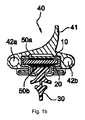
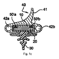
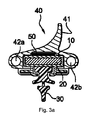
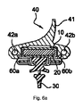
これらの図の全ては、押出し成形半剛性プラスチック材料により作製された縦長基板10を含む車両ウィンドウワイパーを断面で示している。基板10は、「可撓性ブレード」または「フラットブレード」技術により、ワイパーのほぼ全長に亘って延びる剛性向上金属ロッド20または「スプライン」を受け入れるように構成されている凹溝11を備えている。基板10は更に、縦長の爪部12を有し、この爪部12に、エラストマーにより形成されるワイパーブレード30が挿入される。
All of these figures show in cross section a vehicle window wiper that includes an
押出し成形により、基板10とは別体として成形されたアクセサリー40は、縦長基板10に組み付けられ、そして固定される。これらの図においては、アクセサリー40は、少なくとも1つの縦長チューブ42a,42bにより作製された液体噴射装置を有し、これらの縦長チューブに、孔421a,421bを穿孔して、例えば車両ウィンドウへの洗浄液の噴射を可能にしている。アクセサリー40は通常、1つの材料のみによって形成される。この場合には、押出成形エラストマーにより形成されている。
The
更に、これらの図においては、風向調整ディフレクター41が、アクセサリー40に設けられ、車両のウィンドウに対するワイピングブレード30の接触を向上させるようになっていることに、注目に値することである。しかしながら、ほとんどの場合において、このような風向調整ディフレクター41は、本発明にとって必須ではないことに留意されたい。図5に示す実施形態のみが、このようなディフレクターを設けることを暗に示している。
Furthermore, in these figures, it is noteworthy that the wind
スプレーチューブまたはスプレーチューブ群に収容され、かつ外気温度がマイナスの状態で凍結する可能性のある洗浄液を加熱するために、本発明においては、洗浄液を加熱する手段を、ワイパーの少なくとも1つの構造部材に一体化する構成が提供されている。従って、液相の洗浄液を、少なくとも0℃の温度にする場合、一方においては、噴射装置の噴射機能を、このような機能は、洗浄液を少なくとも0℃の温度にすることができない場合には、当該洗浄液が凍結することにより作動しなくなるので、復旧させることが可能であり、そして他方においては、ワイパーの構造に、「可撓性ブレード」技術の本質として要求される可撓性を復旧させることができる。その理由は、洗浄液がスプレーチューブ内で凍結して、剛性が生じることが原因でこのような可撓性が制限される可能性があるからである。 In order to heat the cleaning liquid contained in the spray tube or the spray tube group and which may freeze in a state where the outside air temperature is negative, in the present invention, at least one structural member of the wiper is used as a means for heating the cleaning liquid. An integrated configuration is provided. Therefore, when the liquid phase cleaning liquid is brought to a temperature of at least 0 ° C., on the one hand, the jetting function of the jet device, such a function, when the cleaning liquid cannot be brought to a temperature of at least 0 ° C. It can be restored as the cleaning fluid becomes inoperable due to freezing, and on the other hand, the wiper structure is restored to the flexibility required as the essence of the “flexible blade” technology. Can do. The reason is that the flexibility may be limited due to the fact that the cleaning liquid freezes in the spray tube and causes rigidity.
図1a〜図3aは、加熱手段が、少なくとも1つの加熱抵抗膜により構成されている第1の実施形態に関連するものであるのに対して、図4〜図6bは、少なくとも1つの加熱抵抗ワイヤを、加熱手段として実装した第2の実施形態を示している。 1a to 3a relate to the first embodiment in which the heating means is constituted by at least one heating resistance film, whereas FIGS. 4 to 6b show at least one heating resistance. The 2nd Embodiment which mounted the wire as a heating means is shown.
図1a〜図3aの第1の実施形態の別の解決策においては、ワイパーの構造の種々の部材の上に、1つの加熱抵抗膜のみが配置されている。 In another solution of the first embodiment of FIGS. 1a to 3a, only one heating resistive film is arranged on the various members of the wiper structure.
図1aでは、加熱抵抗膜50は、剛性向上金属ロッド20の1つの面に配置されている。この膜50は、例えば自動接着性の連続する細長片により形成され、この細長片は、切断して所望の長さにすることができ、かつ接着剤の保護膜を剥がした後には、どのような面にも固着させることができる。
In FIG. 1 a, the
この別の解決策によると、ロッド20の金属の正しい熱伝導率を利用して、膜50により発生する熱を、スプレーチューブ42a,42bに向かって迅速に拡散させることができるという利点がもたらされる。熱が、剛性向上ロッド20を通して、このように迅速に拡散させることによって、更に、構造の温度が更に均一になり、これによって、特定の部材群、具体的には、プラスチック材料またはエラストマーにより形成され、かつ変形する可能性があるか、または温度が極めて高くなる領域に、局部的に閉じ込められる可能性のある部材の劣化を防止することができるという利点が得られる。
This alternative solution provides the advantage that the correct thermal conductivity of the metal of the
図2aの別の解決策では、加熱抵抗膜50を、縦長基板10の1つの面に配置してある。
In another solution of FIG. 2 a, the
図3aの別の解決策では、加熱抵抗膜50を、アクセサリー40におけるアクセサリー40を支持体10に組み付ける方の面に配置する。
In another solution of FIG. 3 a, the
図1b〜図3bの別の解決策は、2つの加熱抵抗膜50a,50bを備えているので、更に高効率の加熱、及びワイパーの構造内で発生する熱の分布が、より良好に行われる。
The alternative solution of FIGS. 1b-3b includes two heating
図1bでは、両方の膜50a,50bは、剛性向上ロッド20の両反対面に配置されている。
In FIG. 1b, both
図2bでは、両方の膜50a,50bは、縦長基板10の両反対面に配置されている。
In FIG. 2 b, both
図3bでは、両方の膜50a,50bは、それぞれ、アクセサリー40を縦長基板10に組み付ける面に、そして前記縦長基板10のうち、組み付け面とは反対側の面に配置されている。
In FIG. 3 b, both
図1cは、非常に有利な別の解決策を示している。その理由は、この解決策によれば、2つの加熱抵抗膜50’a,50’bを、剛性向上金属ロッド20の同じ面に配置し、これらの膜の各膜を、ロッドの辺縁部に配置して、それぞれが、スプレーチューブ42a,42bに出来る限り近くなる構成を提供することができるからである。このような構成によると、これらの膜により発生する熱が、チューブ42a,42bに向かって拡散し易くなり、チューブに収容される洗浄液を、より効率的に、かつより迅速に加熱することができる。2つの他の加熱抵抗膜を、剛性向上ロッド20のうちの前述の面とは反対側の面の辺縁部に追加する構成を考えることもできる。
FIG. 1c shows another very advantageous solution. The reason is that according to this solution, the two
図4に示す実施形態の例示的な形態では、加熱抵抗ワイヤ60a,60bを、それぞれ、スプレーチューブ42a,42b内に格納してある。従って、洗浄液を直接加熱して、極めて高いエネルギー収率を確保する構成が得られる。その理由は、加熱ワイヤ60a,60bにおけるジュール効果による発熱量のほぼ全てが、洗浄液に伝達されるからである。
In the exemplary form of the embodiment shown in FIG. 4,
しかし、図4の別の解決策は、加熱ワイヤによってスプレー孔421a,421bが、これらのワイヤを、チューブ42a,42b内に格納しているので、目詰まりする可能性があるという不具合を有する。
However, the alternative solution of FIG. 4 has the disadvantage that the
このような不具合を解決するために、図5の別の解決策では、加熱抵抗ワイヤ60をスプレーチューブ42bの近くで、風向調整ディフレクター41に設けられる縦長空洞411の内部に一体化する構成が提供される。勿論、この場合、チューブ42bに収容される洗浄液だけが、ほとんど凍結しないようにすることができる。この限定的構成によって、基本的にはスプレー機能を50%だけでも復旧させることができるので、実用上の影響が生じることはほとんど無い。
In order to solve such a problem, the other solution of FIG. 5 provides a configuration in which the
ワイヤ群を、これらのチューブ内に格納することに関連する上述の不具合は、図6a,図6bの別の解決策によっても解決することができ、これらの解決策では共通して、2つの加熱ワイヤ60a,60bをアクセサリー40との共押出し成形により押出し成形し、このような加熱ワイヤ群のうちの少なくとも1つが、スプレーチューブに近接配置される特殊な構成を採用する。
The above-mentioned drawbacks associated with storing the wires in these tubes can also be solved by the alternative solutions of FIGS. 6a and 6b, which commonly have two heating The
図6aでは、加熱ワイヤ60a,60bを、それぞれ、2本チューブ構成のアクセサリー40内のチューブ42a,42bに近接配置する。
In FIG. 6a, the
図6bでは、加熱ワイヤ60bのみを、1本チューブ構成のアクセサリー40内のスプレーチューブ42bに近接配置する。この例では、加熱ワイヤ60aは任意であり、ワイパーの構造の残りの部分を加熱するために使用することができる。
In FIG. 6b, only the
共押出し成形によるこの製品は、加熱ワイヤ群を、図4に示すように、チューブ群に挿通させることにより、または図5に示すように、縦長空洞に挿通させることにより得られる製品よりも製造し易い。更に、このようにして加熱ワイヤ群との共押出し成形により押出し成形されるアクセサリー40は、電気ワイヤを切り出すときのように、容易に切断して所望の長さにすることができる。
This product by co-extrusion is manufactured more than the product obtained by inserting a group of heating wires through a tube group as shown in FIG. 4 or through a vertically long cavity as shown in FIG. easy. Furthermore, the
10縦長基板、支持体
12縦長の爪部
20剛性向上金属ロッド
30ワイピングブレード、ワイパーブレード
40アクセサリー
41風向調整ディフレクター
42a,42b縦長チューブ、スプレーチューブ
50,50a,50b,50’a,50’b加熱抵抗膜
60,60a,60b加熱抵抗ワイヤ
411縦長空洞
421a,421bスプレー孔
10 vertical substrate,
Claims (6)
−縦長基板(10)と、
−前記基板(10)の延在部(11)として配置される剛性向上ロッド(20)と、
−前記基板(10)に固定されるワイピングブレード(30)と、
−洗浄液を噴射する少なくとも1つのチューブ(42a,42b)を含み、かつ前記基板(10)に組み付けられるアクセサリー(40)とを備え、前記ワイパーは更に、前記洗浄液を加熱する手段(50;50a,50b;50’a,50’b)を含み、前記加熱手段(50;50a,50b;50’a,50’b)は、前記剛性向上ロッド(20)に設けられていることを特徴とする、車両ウィンドウワイパー。 A vehicle window wiper comprising the following structural members:
A vertically elongated substrate (10);
A rigidity improving rod (20) arranged as an extension (11) of the substrate (10);
A wiping blade (30) fixed to the substrate (10);
An accessory (40) comprising at least one tube (42a, 42b) for spraying the cleaning liquid and assembled to the substrate (10), the wiper further comprising means for heating the cleaning liquid (50; 50a, 50b; 50′a, 50′b), and the heating means (50; 50a, 50b; 50′a, 50′b) is provided on the rigidity improving rod (20). , Vehicle window wiper.
Applications Claiming Priority (3)
| Application Number | Priority Date | Filing Date | Title |
|---|---|---|---|
| FR0801632 | 2008-03-26 | ||
| FR0801632A FR2929215B1 (en) | 2008-03-26 | 2008-03-26 | WIPER BLADE FOR VEHICLE WINDOWS |
| PCT/EP2009/053370 WO2009118286A1 (en) | 2008-03-26 | 2009-03-23 | Wiper for vehicle windows |
Publications (2)
| Publication Number | Publication Date |
|---|---|
| JP2011515274A JP2011515274A (en) | 2011-05-19 |
| JP5475751B2 true JP5475751B2 (en) | 2014-04-16 |
Family
ID=39816619
Family Applications (1)
| Application Number | Title | Priority Date | Filing Date |
|---|---|---|---|
| JP2011501186A Active JP5475751B2 (en) | 2008-03-26 | 2009-03-23 | Vehicle window wiper |
Country Status (13)
| Country | Link |
|---|---|
| US (1) | US8499407B2 (en) |
| EP (3) | EP2712775B1 (en) |
| JP (1) | JP5475751B2 (en) |
| KR (1) | KR101579996B1 (en) |
| CN (2) | CN101980900A (en) |
| BR (1) | BRPI0909086A2 (en) |
| ES (1) | ES2464101T3 (en) |
| FR (1) | FR2929215B1 (en) |
| HU (2) | HUE032201T2 (en) |
| MX (1) | MX2010010477A (en) |
| PL (3) | PL2268512T3 (en) |
| RU (1) | RU2502620C2 (en) |
| WO (1) | WO2009118286A1 (en) |
Families Citing this family (46)
| Publication number | Priority date | Publication date | Assignee | Title |
|---|---|---|---|---|
| WO2010044768A1 (en) * | 2008-10-13 | 2010-04-22 | Malone Randolph W | Frameless, heated wiper assembly and system utilizing same |
| DE102009014313A1 (en) * | 2009-03-25 | 2010-09-30 | Valeo Systèmes d'Essuyage | wiper blade |
| DE102009032376A1 (en) | 2009-07-08 | 2011-02-03 | Valeo Systèmes d'Essuyage | Flat wiper blade |
| FR2952883B1 (en) * | 2009-11-23 | 2012-12-14 | Peugeot Citroen Automobiles Sa | ICE WIPER BLADE INTEGRATING A WASHING LIQUID CONDUIT |
| DE102010007557A1 (en) | 2010-02-10 | 2011-08-11 | Valeo Wischersysteme GmbH, 74321 | Wiper device for vehicle windows and wiper blade with a heating device |
| CN102069775A (en) * | 2010-06-13 | 2011-05-25 | 无锡核力重工有限公司 | Windscreen wiper of vehicle |
| FR2962092B1 (en) * | 2010-06-30 | 2013-06-28 | Valeo Systemes Dessuyage | WIPER ADAPTER WITH ELECTRICAL CONTACTS |
| WO2012006363A2 (en) | 2010-07-06 | 2012-01-12 | Hwb, Llc | Improved heated wiper blade for motor vehicles and the like |
| US9533656B2 (en) | 2010-07-06 | 2017-01-03 | Hwb, Llc | Heated wiper blade for motor vehicles and the like |
| FR2963595B1 (en) | 2010-08-05 | 2013-09-27 | Valeo Systemes Dessuyage | WIPER BLADE |
| FR2965235B1 (en) * | 2010-09-29 | 2018-01-26 | Valeo Systemes D'essuyage | HEATING AND TRANSPORTING CONDUIT OF A WINDSCREEN ICE WIPER LIQUID WITH TWO RINSING RINSES, WIPING DEVICE AND METHOD OF MANUFACTURING |
| DE102010056462A1 (en) * | 2010-12-30 | 2012-07-05 | Valeo Systèmes d'Essuyage | Wiper blade for cleaning windows of motor vehicles |
| FR2973759B1 (en) | 2011-04-06 | 2016-10-21 | Valeo Systemes Dessuyage | LIQUID SPREADING DEVICE FOR WIPING BROOM |
| FR2973758B1 (en) * | 2011-04-06 | 2013-05-17 | Valeo Systemes Dessuyage | ASSEMBLY OF A TIP AND A DEVICE FOR SPRAYING A LIQUID, WIPER BLADE COMPRISING SUCH AN ASSEMBLY, METHOD FOR MOUNTING A DEVICE FOR PROJECTING A LIQUID ON A TIP |
| FR2975060B1 (en) * | 2011-05-09 | 2013-05-24 | Peugeot Citroen Automobiles Sa | WIPER BLADE WITH A LIQUID PROJECTION DEVICE ON THE RACLETTE LIP |
| FR2975064B1 (en) * | 2011-05-13 | 2013-05-17 | Valeo Systemes Dessuyage | LIQUID SPREADING DEVICE FOR WIPING BROOM |
| DE102011078185A1 (en) * | 2011-06-28 | 2013-01-03 | Robert Bosch Gmbh | Wiper device, in particular motor vehicle windshield wiper device |
| FR2977847B1 (en) * | 2011-07-12 | 2014-02-28 | Valeo Systemes Dessuyage | SEMI-RIGID WIPER BLADE WITH RECOVERED SPOILER |
| DE102011086790A1 (en) * | 2011-11-22 | 2013-05-23 | Robert Bosch Gmbh | Wiper blade device with an at least partially formed from a fiber composite spring core |
| DE102011055962A1 (en) * | 2011-12-02 | 2013-06-06 | Valeo Systèmes d'Essuyage | Wiper device for cleaning a vehicle window |
| FR2984258B1 (en) * | 2011-12-19 | 2016-08-05 | Valeo Systemes Dessuyage | ELECTRICAL AND HYDRAULIC CONNECTION DEVICE FOR A SYSTEM FOR SUPPLYING AND / OR DISTRIBUTING IN WINDSCREEN WINDOW |
| FR2987016B1 (en) * | 2012-02-22 | 2014-11-21 | Valeo Systemes Dessuyage | METHOD FOR MELTING GEL AND / OR FROST AND / OR ICE AND / OR SNOW PRESENT ON THE GLASS OF A VEHICLE |
| FR2994144B1 (en) * | 2012-08-02 | 2014-08-29 | Valeo Systemes Dessuyage | CONNECTION DEVICE BETWEEN A WIPER ARM AND A WIPER, COMPRISING A OVERMOLD TUBE |
| CN103661280A (en) * | 2012-09-07 | 2014-03-26 | 张永波 | Protection type automobile wiper |
| FR2999131B1 (en) * | 2012-12-10 | 2015-01-02 | Valeo Systemes Dessuyage | WIPER BLADE |
| FR3003219B1 (en) * | 2013-03-14 | 2016-11-18 | Valeo Systemes Dessuyage | DEVICE FOR DISPENSING WINDSCREEN ICE WIPER BLINK FOR MOTOR VEHICLE WIPER |
| EP2808208A1 (en) * | 2013-05-31 | 2014-12-03 | Valeo Systèmes d'Essuyage | Longitudinal substrate and wiper for motor vehicle |
| FR3014388B1 (en) * | 2013-12-05 | 2017-07-14 | Valeo Systemes Dessuyage | METHOD FOR MANUFACTURING A HEATING ELEMENT FOR A WIPER BLADE OF A VEHICLE |
| FR3014796B1 (en) * | 2013-12-16 | 2017-07-14 | Valeo Systemes Dessuyage | WIPER BLADE FOR A VEHICLE GLASS WIPING SYSTEM AND METHOD OF ASSEMBLING THE SAME |
| FR3017845B1 (en) * | 2014-02-24 | 2016-03-04 | Valeo Systemes Dessuyage | HEAT WIPER BLADE ASSEMBLY OF A VEHICLE, ICE WIPER BLADE COMPRISING THE SAME, AND METHOD OF ASSEMBLING SUCH A WIPER BLADE |
| FR3017847B1 (en) * | 2014-02-24 | 2017-08-18 | Valeo Systemes Dessuyage | SCRUBBER ELEMENT FOR WIPER BLADE |
| FR3018248B1 (en) * | 2014-03-07 | 2016-03-11 | Valeo Systemes Dessuyage | LONGITUDINAL STRUCTURE ELEMENT FOR A WIPER BLADE |
| US9227597B1 (en) * | 2014-06-20 | 2016-01-05 | GM Global Technology Operations LLC | Wiper blade for wiping a surface of a windshield |
| FR3023810B1 (en) * | 2014-07-17 | 2018-01-19 | Valeo Systemes D'essuyage | FLAT WHEAT FLAT BRUSH |
| WO2016009005A1 (en) * | 2014-07-17 | 2016-01-21 | Valeo Systèmes d'Essuyage | Flat faired window wiper blade |
| FR3023775B1 (en) * | 2014-07-17 | 2016-08-05 | Valeo Systemes Dessuyage | FLAT WHEAT FLAT BRUSH |
| KR101655536B1 (en) | 2014-09-24 | 2016-09-07 | 현대자동차주식회사 | Washer nozzle integrated wiper blade |
| FR3037544B1 (en) * | 2015-06-16 | 2018-11-02 | Valeo Systemes D'essuyage | ICE WIPER BLADE COMPRISING A THERMOCONDUCTIVE MATERIAL |
| DE102016205415A1 (en) * | 2016-04-01 | 2017-10-05 | Robert Bosch Gmbh | Spraying device for a wiper blade |
| FR3058009B1 (en) * | 2016-10-25 | 2018-11-09 | Valeo Systemes D'essuyage | ASSEMBLY FOR MOTOR VEHICLE COMPRISING AUTOMOTIVE EQUIPMENT AND PIEZOELECTRIC ELEMENT |
| EP3351439B1 (en) * | 2017-01-24 | 2019-11-20 | Valeo Systèmes d'Essuyage | Wiper blade comprising an electrical heating circuit and a ptc fuse |
| FR3066741B1 (en) | 2017-05-24 | 2020-01-03 | Valeo Systemes D'essuyage | DEVICE FOR CONTROLLING AND REGULATING A WIPER BLADE HEATING CIRCUIT |
| DE102018200316A1 (en) | 2018-01-11 | 2019-07-11 | Robert Bosch Gmbh | Wiper blade device |
| FR3080815B1 (en) * | 2018-05-02 | 2021-04-02 | Valeo Systemes Dessuyage | MOTOR VEHICLE AIR DEFLECTOR |
| FR3086615B1 (en) * | 2018-09-28 | 2020-12-04 | Valeo Systemes Dessuyage | MOTOR VEHICLE DRIVING ASSISTANCE SYSTEM |
| DE102018222242A1 (en) * | 2018-12-19 | 2020-06-25 | Robert Bosch Gmbh | Wiper blade, in particular for a motor vehicle |
Family Cites Families (32)
| Publication number | Priority date | Publication date | Assignee | Title |
|---|---|---|---|---|
| US1658389A (en) * | 1921-07-26 | 1928-02-07 | Trico Products Corp | Cleaner for windshields and the like |
| US2561188A (en) * | 1948-05-01 | 1951-07-17 | Marvin D Ferguson | Windshield protector |
| US3574881A (en) * | 1969-06-16 | 1971-04-13 | Reinhold Temple | Heated windshield wiper-spray assembly |
| JPS5136841U (en) * | 1974-09-12 | 1976-03-18 | ||
| JPS53133836A (en) * | 1977-04-25 | 1978-11-22 | Toruku Kougiyou Kk | Wind wiper |
| US4194261A (en) * | 1978-05-01 | 1980-03-25 | Tutco, Inc. | Heated wiper arrangement |
| SU799984A1 (en) * | 1979-04-06 | 1981-01-30 | Klimenko Boris P | Vehicle windscreen wiper |
| SU956332A1 (en) * | 1980-12-15 | 1982-09-07 | Завод По Производству Автоприборов Министерства Автомобильной Промышленности | Vehicle wind-shield wiper brush |
| JPS6444867U (en) * | 1987-09-14 | 1989-03-17 | ||
| US4967437A (en) * | 1988-05-27 | 1990-11-06 | Engineering Plastics, Inc. | Heated wiper blade assembly |
| DE3841133A1 (en) * | 1988-12-07 | 1990-06-13 | Guenther Petermann | WIPER BLADE |
| JPH02132565U (en) * | 1989-04-11 | 1990-11-02 | ||
| US5426814A (en) * | 1994-01-31 | 1995-06-27 | Minnick; Leonard J. | Heated windshield wiper with fluid dispensing means |
| DE4404409A1 (en) * | 1994-02-11 | 1995-08-17 | Kammerer Gmbh M | Windscreen washer system for motor vehicles |
| US5603856A (en) * | 1994-11-04 | 1997-02-18 | Lon Baker | Electrically heated windshield wiper with enclosing flexible shroud |
| US5539951A (en) * | 1995-12-08 | 1996-07-30 | Guell; Ronald R. | Wiper blade assembly including heating and fluid dispensing means |
| KR19980017748A (en) * | 1996-08-31 | 1998-06-05 | 양 재 신 | Car Wiper Blades |
| DE19651733A1 (en) * | 1996-12-12 | 1998-06-18 | Metzeler Automotive Profiles | Heated rubber body |
| US6137084A (en) * | 1998-10-07 | 2000-10-24 | Thomas; Paul Douglas | Heating element for heated windshield wiper |
| DE19950741A1 (en) * | 1999-10-21 | 2001-05-10 | Bosch Gmbh Robert | Wiper blade for a window of a vehicle and method for connecting a rail and a wiper body to one another to form a wiper element for a wiper blade |
| AU2001278396A1 (en) * | 2000-07-27 | 2002-02-13 | Robert Bosch G.M.B.H | Wiper arm, wiper blade and wiper device, especially for the panes of a motor vehicle |
| DE10039290B4 (en) * | 2000-08-11 | 2013-01-31 | Valeo Auto-Electric Wischer Und Motoren Gmbh | wiper device |
| DE10056705A1 (en) * | 2000-11-15 | 2002-05-16 | Volkswagen Ag | Windscreen wiper for motor vehicle has blade with heating element in connection with screen heater |
| DE10116499A1 (en) * | 2001-04-03 | 2002-10-24 | Joerg Runge-Rannow | Heated wipers |
| DE10234267A1 (en) | 2002-07-27 | 2004-02-05 | Robert Bosch Gmbh | Wiper blade for cleaning motor vehicle windscreens has a flexible ribbon-type elongated supporting element and an element for heating the wiper blade to ensure movement in winter conditions |
| FR2846928B1 (en) * | 2002-11-08 | 2004-12-17 | Peugeot Citroen Automobiles Sa | WIPER BLADE FOR AUTOMOTIVE WIPER BLADE. |
| DE102004007351A1 (en) * | 2004-02-16 | 2005-09-01 | Volkswagen Ag | Washer fitting for windscreen wiper has a hollow wiper arm fitted with an adaptor with washer jets and supporting the wiper blade assembly |
| US20060191095A1 (en) * | 2005-02-28 | 2006-08-31 | Valeo Electrical Systems, Inc. | Composite buckling spring in compression spring wiper arm |
| DE102005030201A1 (en) | 2005-06-29 | 2007-01-11 | Valeo Systèmes d`Essuyage | wiper device |
| DE202005016941U1 (en) * | 2005-10-28 | 2007-03-08 | Schmitt, Michael | Windshield wiper for vehicle windscreen, has wiper profile with stripper for attachment of vehicle windscreens whereby wiper profile acceptor is provided for accepting wiper profile |
| CN201002587Y (en) * | 2006-12-28 | 2008-01-09 | 高峥嵘 | Electric heating wiper |
| FI120968B (en) * | 2007-02-13 | 2010-05-31 | Keijo Vornanen | Windscreen wiper |
-
2008
- 2008-03-26 FR FR0801632A patent/FR2929215B1/en active Active
-
2009
- 2009-03-23 HU HUE13199250A patent/HUE032201T2/en unknown
- 2009-03-23 EP EP13199252.1A patent/EP2712775B1/en active Active
- 2009-03-23 EP EP09723955.2A patent/EP2268512B1/en active Active
- 2009-03-23 HU HUE13199252A patent/HUE032202T2/en unknown
- 2009-03-23 CN CN2009801100396A patent/CN101980900A/en active Pending
- 2009-03-23 KR KR1020107023429A patent/KR101579996B1/en active IP Right Grant
- 2009-03-23 WO PCT/EP2009/053370 patent/WO2009118286A1/en active Application Filing
- 2009-03-23 RU RU2010143569/11A patent/RU2502620C2/en not_active IP Right Cessation
- 2009-03-23 JP JP2011501186A patent/JP5475751B2/en active Active
- 2009-03-23 PL PL09723955T patent/PL2268512T3/en unknown
- 2009-03-23 BR BRPI0909086A patent/BRPI0909086A2/en not_active IP Right Cessation
- 2009-03-23 EP EP13199250.5A patent/EP2712774B1/en active Active
- 2009-03-23 ES ES09723955.2T patent/ES2464101T3/en active Active
- 2009-03-23 PL PL13199250T patent/PL2712774T3/en unknown
- 2009-03-23 US US12/933,587 patent/US8499407B2/en active Active
- 2009-03-23 MX MX2010010477A patent/MX2010010477A/en active IP Right Grant
- 2009-03-23 CN CN201410148098.5A patent/CN103909905B/en active Active
- 2009-03-23 PL PL13199252T patent/PL2712775T3/en unknown
Also Published As
| Publication number | Publication date |
|---|---|
| EP2712774A3 (en) | 2014-10-08 |
| EP2712775A3 (en) | 2014-08-27 |
| KR20100125433A (en) | 2010-11-30 |
| EP2712775B1 (en) | 2016-09-07 |
| EP2268512A1 (en) | 2011-01-05 |
| US8499407B2 (en) | 2013-08-06 |
| EP2712775A2 (en) | 2014-04-02 |
| KR101579996B1 (en) | 2015-12-23 |
| RU2502620C2 (en) | 2013-12-27 |
| WO2009118286A1 (en) | 2009-10-01 |
| EP2712774B1 (en) | 2016-09-07 |
| PL2712774T3 (en) | 2017-06-30 |
| PL2712775T3 (en) | 2017-06-30 |
| EP2712774A2 (en) | 2014-04-02 |
| ES2464101T3 (en) | 2014-05-30 |
| MX2010010477A (en) | 2010-10-20 |
| HUE032202T2 (en) | 2017-09-28 |
| RU2010143569A (en) | 2012-05-10 |
| CN103909905A (en) | 2014-07-09 |
| JP2011515274A (en) | 2011-05-19 |
| PL2268512T3 (en) | 2014-07-31 |
| CN101980900A (en) | 2011-02-23 |
| BRPI0909086A2 (en) | 2015-09-29 |
| HUE032201T2 (en) | 2017-09-28 |
| EP2268512B1 (en) | 2014-03-05 |
| FR2929215B1 (en) | 2010-04-02 |
| US20110016653A1 (en) | 2011-01-27 |
| CN103909905B (en) | 2016-08-17 |
| FR2929215A1 (en) | 2009-10-02 |
Similar Documents
| Publication | Publication Date | Title |
|---|---|---|
| JP5475751B2 (en) | Vehicle window wiper | |
| US6588048B2 (en) | Wiper-blade device | |
| CN102361784B (en) | Wiper blade | |
| JP6629217B2 (en) | Windscreen wiper device | |
| EP2626257A2 (en) | Pumped-drain and defrost windshield wiper system | |
| JP2014533625A (en) | Windscreen wiper device | |
| EP2983952B1 (en) | Windscreen wiper device | |
| JP2009501664A5 (en) | ||
| CN105270341B (en) | Connecting device between a wiper arm and a wiper blade | |
| JP2014218241A (en) | Accessory and wiper of motor vehicle | |
| KR101493114B1 (en) | Windscreen wiper device | |
| US20080034529A1 (en) | Wiper blade for cleaning glass or polymeric windshields | |
| US20170072910A1 (en) | Longitudinal structural element for a windscreen wiper | |
| CN104859594B (en) | Windscreen wiper including heating element | |
| JP6552490B2 (en) | Glass wiper device | |
| CN107650869B (en) | Electric heating type windscreen wiper, electric heating windscreen wiper system and automobile | |
| KR101585234B1 (en) | Wiper blade for windscreen wiper of vehicle | |
| CN104724066A (en) | Luffer Board Water Scraping Device Possessing Integrated Cleaning Function | |
| US20160288774A1 (en) | Windscreen wiper device for a vehicle | |
| FR3025473A1 (en) | ICE WIPER COMPRISING A AXIS WITH A SPRAY | |
| JP2017007656A (en) | Windscreen wiper blade incorporating heat-conducting material | |
| JP5673981B2 (en) | Windshield wiper device | |
| US20160347284A1 (en) | Windscreen wiping device | |
| CN108263344B (en) | Wiper blade, wiper and motor vehicle comprising same | |
| JP2017094861A (en) | Wiper rubber and wiper of using the same |
Legal Events
| Date | Code | Title | Description |
|---|---|---|---|
| A621 | Written request for application examination |
Free format text: JAPANESE INTERMEDIATE CODE: A621 Effective date: 20120207 |
|
| A977 | Report on retrieval |
Free format text: JAPANESE INTERMEDIATE CODE: A971007 Effective date: 20130830 |
|
| A131 | Notification of reasons for refusal |
Free format text: JAPANESE INTERMEDIATE CODE: A131 Effective date: 20130903 |
|
| A521 | Request for written amendment filed |
Free format text: JAPANESE INTERMEDIATE CODE: A523 Effective date: 20131203 |
|
| TRDD | Decision of grant or rejection written | ||
| A01 | Written decision to grant a patent or to grant a registration (utility model) |
Free format text: JAPANESE INTERMEDIATE CODE: A01 Effective date: 20140107 |
|
| A61 | First payment of annual fees (during grant procedure) |
Free format text: JAPANESE INTERMEDIATE CODE: A61 Effective date: 20140206 |
|
| R150 | Certificate of patent or registration of utility model |
Ref document number: 5475751 Country of ref document: JP Free format text: JAPANESE INTERMEDIATE CODE: R150 Free format text: JAPANESE INTERMEDIATE CODE: R150 |
|
| R250 | Receipt of annual fees |
Free format text: JAPANESE INTERMEDIATE CODE: R250 |
|
| R250 | Receipt of annual fees |
Free format text: JAPANESE INTERMEDIATE CODE: R250 |
|
| R250 | Receipt of annual fees |
Free format text: JAPANESE INTERMEDIATE CODE: R250 |
|
| R250 | Receipt of annual fees |
Free format text: JAPANESE INTERMEDIATE CODE: R250 |
|
| R250 | Receipt of annual fees |
Free format text: JAPANESE INTERMEDIATE CODE: R250 |
|
| R250 | Receipt of annual fees |
Free format text: JAPANESE INTERMEDIATE CODE: R250 |
|
| R250 | Receipt of annual fees |
Free format text: JAPANESE INTERMEDIATE CODE: R250 |
|
| R250 | Receipt of annual fees |
Free format text: JAPANESE INTERMEDIATE CODE: R250 |