EP3351439B1 - Wiper blade comprising an electrical heating circuit and a ptc fuse - Google Patents
Wiper blade comprising an electrical heating circuit and a ptc fuse Download PDFInfo
- Publication number
- EP3351439B1 EP3351439B1 EP17305073.3A EP17305073A EP3351439B1 EP 3351439 B1 EP3351439 B1 EP 3351439B1 EP 17305073 A EP17305073 A EP 17305073A EP 3351439 B1 EP3351439 B1 EP 3351439B1
- Authority
- EP
- European Patent Office
- Prior art keywords
- wiper blade
- heating
- support
- resistive element
- fuse
- Prior art date
- Legal status (The legal status is an assumption and is not a legal conclusion. Google has not performed a legal analysis and makes no representation as to the accuracy of the status listed.)
- Active
Links
Images

Classifications
-
- B—PERFORMING OPERATIONS; TRANSPORTING
- B60—VEHICLES IN GENERAL
- B60S—SERVICING, CLEANING, REPAIRING, SUPPORTING, LIFTING, OR MANOEUVRING OF VEHICLES, NOT OTHERWISE PROVIDED FOR
- B60S1/00—Cleaning of vehicles
- B60S1/02—Cleaning windscreens, windows or optical devices
- B60S1/04—Wipers or the like, e.g. scrapers
- B60S1/32—Wipers or the like, e.g. scrapers characterised by constructional features of wiper blade arms or blades
- B60S1/38—Wiper blades
- B60S1/3803—Wiper blades heated wiper blades
- B60S1/3805—Wiper blades heated wiper blades electrically
-
- H—ELECTRICITY
- H01—ELECTRIC ELEMENTS
- H01C—RESISTORS
- H01C7/00—Non-adjustable resistors formed as one or more layers or coatings; Non-adjustable resistors made from powdered conducting material or powdered semi-conducting material with or without insulating material
- H01C7/02—Non-adjustable resistors formed as one or more layers or coatings; Non-adjustable resistors made from powdered conducting material or powdered semi-conducting material with or without insulating material having positive temperature coefficient
-
- H—ELECTRICITY
- H02—GENERATION; CONVERSION OR DISTRIBUTION OF ELECTRIC POWER
- H02H—EMERGENCY PROTECTIVE CIRCUIT ARRANGEMENTS
- H02H9/00—Emergency protective circuit arrangements for limiting excess current or voltage without disconnection
- H02H9/02—Emergency protective circuit arrangements for limiting excess current or voltage without disconnection responsive to excess current
- H02H9/026—Current limitation using PTC resistors, i.e. resistors with a large positive temperature coefficient
-
- H—ELECTRICITY
- H05—ELECTRIC TECHNIQUES NOT OTHERWISE PROVIDED FOR
- H05B—ELECTRIC HEATING; ELECTRIC LIGHT SOURCES NOT OTHERWISE PROVIDED FOR; CIRCUIT ARRANGEMENTS FOR ELECTRIC LIGHT SOURCES, IN GENERAL
- H05B3/00—Ohmic-resistance heating
- H05B3/10—Heater elements characterised by the composition or nature of the materials or by the arrangement of the conductor
- H05B3/18—Heater elements characterised by the composition or nature of the materials or by the arrangement of the conductor the conductor being embedded in an insulating material
-
- H—ELECTRICITY
- H05—ELECTRIC TECHNIQUES NOT OTHERWISE PROVIDED FOR
- H05B—ELECTRIC HEATING; ELECTRIC LIGHT SOURCES NOT OTHERWISE PROVIDED FOR; CIRCUIT ARRANGEMENTS FOR ELECTRIC LIGHT SOURCES, IN GENERAL
- H05B3/00—Ohmic-resistance heating
- H05B3/84—Heating arrangements specially adapted for transparent or reflecting areas, e.g. for demisting or de-icing windows, mirrors or vehicle windshields
-
- B—PERFORMING OPERATIONS; TRANSPORTING
- B60—VEHICLES IN GENERAL
- B60S—SERVICING, CLEANING, REPAIRING, SUPPORTING, LIFTING, OR MANOEUVRING OF VEHICLES, NOT OTHERWISE PROVIDED FOR
- B60S1/00—Cleaning of vehicles
- B60S1/02—Cleaning windscreens, windows or optical devices
- B60S1/04—Wipers or the like, e.g. scrapers
- B60S1/32—Wipers or the like, e.g. scrapers characterised by constructional features of wiper blade arms or blades
- B60S1/38—Wiper blades
- B60S1/3806—Means, or measures taken, for influencing the aerodynamic quality of the wiper blades
- B60S1/381—Spoilers mounted on the squeegee or on the vertebra
-
- B—PERFORMING OPERATIONS; TRANSPORTING
- B60—VEHICLES IN GENERAL
- B60S—SERVICING, CLEANING, REPAIRING, SUPPORTING, LIFTING, OR MANOEUVRING OF VEHICLES, NOT OTHERWISE PROVIDED FOR
- B60S1/00—Cleaning of vehicles
- B60S1/02—Cleaning windscreens, windows or optical devices
- B60S1/04—Wipers or the like, e.g. scrapers
- B60S1/32—Wipers or the like, e.g. scrapers characterised by constructional features of wiper blade arms or blades
- B60S1/38—Wiper blades
- B60S1/3848—Flat-type wiper blade, i.e. without harness
- B60S1/3874—Flat-type wiper blade, i.e. without harness with a reinforcing vertebra
- B60S1/3875—Flat-type wiper blade, i.e. without harness with a reinforcing vertebra rectangular section
- B60S1/3881—Flat-type wiper blade, i.e. without harness with a reinforcing vertebra rectangular section in additional element, e.g. spoiler
-
- B—PERFORMING OPERATIONS; TRANSPORTING
- B60—VEHICLES IN GENERAL
- B60S—SERVICING, CLEANING, REPAIRING, SUPPORTING, LIFTING, OR MANOEUVRING OF VEHICLES, NOT OTHERWISE PROVIDED FOR
- B60S1/00—Cleaning of vehicles
- B60S1/02—Cleaning windscreens, windows or optical devices
- B60S1/04—Wipers or the like, e.g. scrapers
- B60S1/32—Wipers or the like, e.g. scrapers characterised by constructional features of wiper blade arms or blades
- B60S1/40—Connections between blades and arms
- B60S1/4006—Connections between blades and arms for arms provided with a hook-shaped end
-
- B—PERFORMING OPERATIONS; TRANSPORTING
- B60—VEHICLES IN GENERAL
- B60S—SERVICING, CLEANING, REPAIRING, SUPPORTING, LIFTING, OR MANOEUVRING OF VEHICLES, NOT OTHERWISE PROVIDED FOR
- B60S1/00—Cleaning of vehicles
- B60S1/02—Cleaning windscreens, windows or optical devices
- B60S1/04—Wipers or the like, e.g. scrapers
- B60S1/32—Wipers or the like, e.g. scrapers characterised by constructional features of wiper blade arms or blades
- B60S1/38—Wiper blades
- B60S2001/3843—Wiper blades equipped with removable cover or protective elements
-
- H—ELECTRICITY
- H05—ELECTRIC TECHNIQUES NOT OTHERWISE PROVIDED FOR
- H05B—ELECTRIC HEATING; ELECTRIC LIGHT SOURCES NOT OTHERWISE PROVIDED FOR; CIRCUIT ARRANGEMENTS FOR ELECTRIC LIGHT SOURCES, IN GENERAL
- H05B2203/00—Aspects relating to Ohmic resistive heating covered by group H05B3/00
- H05B2203/02—Heaters using heating elements having a positive temperature coefficient
-
- H—ELECTRICITY
- H05—ELECTRIC TECHNIQUES NOT OTHERWISE PROVIDED FOR
- H05B—ELECTRIC HEATING; ELECTRIC LIGHT SOURCES NOT OTHERWISE PROVIDED FOR; CIRCUIT ARRANGEMENTS FOR ELECTRIC LIGHT SOURCES, IN GENERAL
- H05B2203/00—Aspects relating to Ohmic resistive heating covered by group H05B3/00
- H05B2203/031—Heaters specially adapted for heating the windscreen wiper area
Landscapes
- Engineering & Computer Science (AREA)
- Mechanical Engineering (AREA)
- Microelectronics & Electronic Packaging (AREA)
- Power Engineering (AREA)
- Ceramic Engineering (AREA)
- Physics & Mathematics (AREA)
- Electromagnetism (AREA)
- Resistance Heating (AREA)
- Air-Conditioning For Vehicles (AREA)
- Thermistors And Varistors (AREA)
Description
- The invention relates to a wiper blade comprising a heating electrical circuit embodied in the form of at least one heating resistive element and comprising a component for regulating the electric power supply current of the heating electrical circuit. Document
US 2004/0006839 A1 discloses a wiper blade according to the preamble of claim 1. - In a known manner, a wiper blade of a motor vehicle can be heated, in particular to de-ice it in winter or to use the heat produced by the heating means also to de-ice the outside surface of the window the wiper must clean.
- When the wiper blade comprises internal channels for distributing a screen washing liquid, heating the wiper blade can furthermore make it possible to heat the screen washing liquid before it is misted or projected onto the outside surface of the window, which also makes it possible to simplify operations of de-icing the window and can possibly make it possible to avoid using a manual scraper.
- In a known manner, a wiper blade of the "Flat blade" type comprises a body with a longitudinal orientation, which supports a wiper strip, generally made in natural or synthetic rubber, which is designed to rub against the outside surface of the window to be wiped, for example a windscreen of a vehicle, in order to evacuate water from it by taking this water out of the field of view of the driver.
- Such a type of wiper blade also comprises at least one longitudinal spline, which imparts bending on the wiper strip so as to assist the application of the wiper strip on the outside surface of the window.
- The wiper blade is supported by a wiper arm or driving arm that is driven in an alternating movement by an electric driving motor.
- The means for attaching the wiper blade to the driving arm can comprise a connector, which is made integral with the longitudinal body, and an adapter, which is mounted to hinge on the longitudinal body, and which is fastened to a free end of the arm.
- In a known manner, the heating means call upon a heating electrical circuit, which comprises at least one heating resistive element, such as a heating electrical resistor, which, when it is supplied with electric current, produces heat, which is dispersed into its surroundings.
- For example, it has already been proposed to equip the spline for bending a wiper blade with heating means presented in the form of an applied film, which is bonded to at least one of the two opposite flat faces of the spline, and which comprises a heating electrical circuit.
- The heating electrical circuit is, for example, a loop of an electrical wire for conducting electricity, whose ends are connected to terminals for supplying electric current.
- In the case of a vehicle said to be top range, controlling and protecting the function of heating a wiper blade generally take place directly by means of the electronics and of the electrical circuit of the vehicle.
- The function of controlling the heating needs in this case to be integrated during the general definition of the electrical architecture of the vehicle, and said function therefore generates a certain cost.
- Controlling the heating of the heated blades can take place by taking account of parameters supplied for example by a temperature sensor of the vehicle and/or a speed sensor of the vehicle.
- In a general manner, the heating function is triggered below an outside temperature of +5ºC in order to ensure overall de-icing of the wiper blade, either of channels for distributing screen washing or de-icing liquid, means for attaching the wiper blade to the wiper arm, or even the wiper strip in contact with the windscreen.
- Supposing that a sensor were to supply incorrect information such as, for example, the vehicle is running at 150 km/h whereas the vehicle is stopped, or the outside temperature is negative in high summer, an electronic management and controlling module could activate an inappropriate power supply voltage such as for example a voltage of 16 volts instead of a reduced voltage when the vehicle stops, which would bring about a very significant temperature increase and could cause deterioration and even destruction of the heating film equipping the wiper blade.
- For example, the effect would be permanent heating of the wiper blade beyond +5ºC, potentially in high summer with ambient temperatures above +30°C, with a potential risk capable of causing a hot spot, a short-circuit, physical deterioration of the wiper blade, even the start of a fire in the worst case.
- The other functions of the vehicle are therefore not affected in the deteriorated mode of the function, for example in the event of wrong information being supplied by an outside temperature or vehicle running speed sensor, or in the event of failure of such a sensor.
- In order to avoid such problems, document
US-A1-2013/0193129 has already proposed to call upon a self-regulated heating electrical circuit, which comprises at least one Positive Temperature Coefficient (PTC) electrical conducting element, which, when it is supplied with electric current, produces heat, which is dispersed into its surroundings. - In order to avoid such problems, it has already also been proposed to equip the wiper blade with a regulating component consisting of a heat-fusible fuse, which, when it intervenes, definitively stops the wiper blade heating, making replacement of the wiper blade obligatory. In effect, such a fuse is fitted in series in at least one resistive loop of the heating circuit and its melting definitively interrupts the heating electrical circuit.
- The invention aims to propose a simple, effective and affordable solution to such problems inherent in designs according to the prior art, without having to call upon a dedicated single use component aiming to ensure thermal protection of the heated wiper blade.
- The invention proposes a wiper blade of a vehicle, in particular a motor vehicle, comprising:
- at least one heating resistive element, which is connected to terminals for supplying electric current to said element;
- and at least one component for regulating the electric power supply current,
- A fuse known as resettable, or PTC fuse, is also called a Polymeric Positive Temperature Coefficient (PPTC) device.
- It is a passive electronic component used for protecting against excess current defects in electronic circuits, which consists of a non-linear thermistor, which returns to a conducting state once the current has dropped, thus acting as a circuit breaker, while allowing the circuit which is equipped with it to function once more without having to replace a component.
- The function of such a component is not to release heat, and it is used for its function as a fuse, that is to say, its only function is to cut off the power supply to the heating electrical circuit.
- Such a component is characterized by an admissible permanent current (or ampacity), which is the maximum value of the electric current that can permanently pass through a conductor, a device or a unit without its permanent operating temperature in given conditions being higher than a specified value.
- When the current passing through the component - which has a low electrical resistance in the on-state - exceeds the limit, the component heats beyond a temperature threshold value and the resistance suddenly increases by several orders of magnitude to a "triggered" value, typically of hundreds of kΩ, which greatly limits the current due to the finite impedance of the current source. The triggering current varies according to the component and the circuit.
- The critical material used in a PTC resettable fuse is, for example, a plastic-carbon black composite such as described and shown in American Patent
US-3.243.753 . - The design of PTC fuses is also described and shown in documents
US-A1-2012/0075762 orUS-A1-2015/0146334 . - According to another characteristic of the invention, the PTC fuse is a surface-mounted component, known as a CMS component, which is electrically connected to two electrical connecting areas belonging to the heating resistive element.
- The design of such a CMS component is described and shown, for example, in document
FR-A3-2.792.764 - According to other characteristics of the wiper blade:
- it comprises a support, which, directly or indirectly, supports the heating resistive element;
- the PTC fuse is supported, directly or indirectly, by the support;
- the support is a longitudinally elongated element and, directly or indirectly, at least one substantially flat face of the support supports the heating resistive element;
- directly or indirectly, the one face of the support supports the PTC fuse;
- the terminals for supplying electric current are longitudinally situated in a substantially median zone of the support, said zone extending, for example, from 30 to 70% of the length of the support, measured from one of its opposite longitudinal ends;
- directly or indirectly, the support supports at least one heating resistive element on another substantially flat face;
- the support is a spline for bending or reinforcing the wiper blade;
- the heating resistive element comprises at least one loop whose ends are connected to the terminals for supplying electric current;
- the PTC fuse constitutes a section of the loop;
- the wiper blade comprises a flexible substrate so as to embody the heating resistive element in the form of a heating film;
- it comprises means for attaching the wiper blade to an arm for driving the wiper blade, these attachment means comprising means of electrical connection to the electric power supply terminals;
- it comprises protection and sealing means, which surround the PTC fuse and its electrical connecting areas, and which surround said electrical connection means and the terminals for supplying electric current.
- Other characteristics and advantages of the invention will appear on reading the detailed description that will follow, given as non-limitative and, for whose understanding, reference will be made to the attached drawings, wherein:
-
Figure 1 is an exploded perspective view of a wiper blade of a motor vehicle; -
Figure 2 is a perspective view of a wiper blade of the same type as onFigure 1 , comprising an example of an embodiment of a heating circuit associated with a PTC fuse according to the invention; -
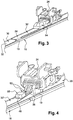
Figure 3 is a larger scale view of a detail of the median longitudinal part of the wiper blade ofFigure 2 ; -
Figure 4 is a larger scale view of a detail of the median longitudinal part of the wiper blade ofFigure 3 , shown without the means for protecting the attachment and electrical connection zones; -
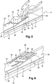
Figure 5 is a view similar to that ofFigure 4 , showing the wiper blade without the intermediate connector, which allows the wiper blade to hinge relative to a driving arm; -
Figure 6 is a view similar to that ofFigure 5 , showing the heating circuit without its PTC fuse; and -
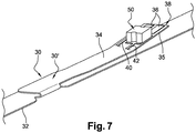
Figure 7 is larger scale view of a detail of the median longitudinal part of the heating circuit and the PTC fuse illustrated onFigure 3 . - In the continuation of the description, elements having an identical structure or similar functions will be designated by the same reference numbers.
- In the continuation of the description, longitudinal, vertical and transverse orientations will be adopted in a non-limitative manner indicated by the trihedron "L,V,T" of the figures. A horizontal plane is also defined, which extends longitudinally and transversally.
- The longitudinal orientation or direction corresponds to the main axis of the wiper blade.
-
Figure 1 shows awiper blade 10, for example, for wiping the outside surface of a motor vehicle windscreen. - An
arm 12 for driving thewiper blade 10 is also partially shown, said arm itself being designed to be driven by an electric motor (not shown) so that the wiper blade follows an alternating back and forth movement making it possible to evacuate water, and possibly other undesirable elements, present on the outside surface of the windscreen. - The
wiper blade 10 comprises alongitudinal body 14, awiper strip 16 and at least onespline 18 whose function here is to impart bending on thewiper strip 16 so as to assist the application of the wiper strip on the outside surface of the windscreen according to the geometric shape in three dimensions in space of said outside surface. - The
longitudinal body 14 of thewiper blade 10 here comprises anupper deflector 20, which is designed to improve the functioning of the wiper blade, the function of thedeflector 20 being to improve the downward pressure of thewiper strip 16 on the outside surface of the windscreen and hence to improve the aerodynamic performance of the wiper system as a whole. - The
wiper blade 10 further comprises end fittings or clips 22 for clipping thewiper strip 16 and thespline 18 to thelongitudinal body 14, theclips 22 here being situated at each of the two opposite longitudinal ends of thelongitudinal body 14. - The
longitudinal body 14 of thewiper blade 10 is embodied here in two independent parts, which are placed one in relation to the other substantially end to end, and which are connected one to the other by anintermediate connector 24. - In order to ensure the assembly and attachment of the
wiper blade 10 on thewiper arm 12, thewiper blade 10 comprises anadapter 26, which is mounted on theintermediate connector 24 and which allows thewiper blade 10 to hinge relative to thearm 12. - The hinging of the
wiper blade 10 relative to thewiper arm 12 is based on a pivoting movement around a pivoting axis A with a transverse orientation orthogonal to the longitudinal axis of thewiper blade 10. - In effect, the
wiper blade 10 must have at least one degree of freedom in rotation or pivoting relative to thewiper arm 12, and more precisely relative to a terminal ordistal part 28 equipping the free end of the drivingarm 12 so as to allow thewiper blade 10 to follow the curve in space of the outside surface of the windscreen. - In a known manner, the
wiper blade 10 is equipped with a heating circuit, which consists essentially of a support and one or more heating resistive elements providing a heating electrical resistance function, said elements being supported by the support, the heating element being integrated in thewiper blade 10. - According to a design such as that illustrated on
Figure 2 and the following figures, the heating circuit is designed to equip one face of aspline 18, and for example theupper face 19. - As can be seen in particular on
Figure 2 , theheating element 30 is presented in the form of a heating film, which is applied to the substantially flatupper face 19 of thebending spline 18. - The
heating film 30 comprises asubstrate 32 made in a material not conducting electricity, which here is of a generally rectangular shape whose dimensions, length and width, are such that they allow theheating film 30 to be adjusted and installed on thebending spline 18 of determined dimensions, here on a median part or portion of the total length of thebending spline 18. - The
substrate 32 is thus, for example, a sheet of flexible plastic or synthetic material. As an example, the heating film consists of two layers of substrate, upper and lower, which encapsulate the heating material, such as, for example, a conducting section, in order to ensure that the film is waterproof. - Without limitation, the
heating film 30 here comprises a median central attachment andelectrical connection part 30', which is a portion folded at one hundred and eighty degrees, which is superposed on the main part of theheating film 30, which is applied to theupper face 19 of thebending spline 18. - The
substrate 32 can comprise, on its lower face designed to cooperate with theupper face 19 of thespline 18, an adhesive coating so as to allow theheating film 30 to be fixed by bonding to said adhesive coating. - The
substrate 32 supports one or more heating resistive elements designed to be connected to a source supplying electric current, here of the motor vehicle. - To that effect, the
heating film 30 comprises twoterminals 36 for supplying electric current, which, as can be seen in particular onFigure 6 , extend here in theupper face 34 of thefree end section 38 of the central part of 30' of theheating film 30. - Each of the
terminals 36 is connected to an associated conductingsection - As can be seen in detail in particular on
Figure 6 , the terminal 36 is connected to a conductingarea 44, which extends broadly transversally, and which is adjacent to anotherparallel conducting area 46, which is connected in turn, in a manner not shown in detail, to the resistive conducting loop. - Thus, on examining
Figure 6 , the heating electrical circuit between theterminals 36 is a circuit interrupted between the conductingareas - The
areas PTC fuse 50 according to the invention as illustrated onFigure 5 . - The
PTC fuse 50 here is a component of the CMS type whose lower face comprises, for example, two connection pins (not shown), each of which is soldered onto an associated electrical connectingarea - As illustrated on
Figure 7 , assembling thePTC fuse 50 with theheating film 30 can be embodied according to a process during which thePTC fuse 50 is fixed by brazing on the associated portion of the heating film so as to constitute a subassembly which is then used like a heating film of the prior art for its assembly, attachment and electrical connection. - Thus, when the
PTC fuse 50 is in its "on" state, the heating electrical circuit is closed and an instruction to supply theheating film 30 with electric current makes it possible to provoke heating of thewiper blade 10. - In order to allow the electrical connection of the
heating film 30, through itspower supply terminals 36, to an electric current source, which belongs, for example, to the motor vehicle equipped with thewiper blade 10, the latter comprises electrical connection means, which are integrated with theintermediate connector 24. - To that effect, the
intermediate connector 24 here comprises two electrical connection pins 52, each of which is designed to be soldered to an associatedterminal 36 for supplying electric current. - Once the different soldering operations have been performed, in order to protect the attachment and electrical connection zones, and in particular to ensure that they are sealed, the embodiment illustrated on the figures plans to cover all of the zone comprising the
power supply terminals 36, the connectingareas PTC fuse 50 and the connection pins 52 with a "capsule" 54 for protection and electrical insulation, which is, for example, embodied by injection moulding in situ of a suitable resin. - It can be advantageous to leave a free space around the
PTC fuse 50 so as to allow the expansion associated with its functioning, which can be obtained by placing a small cap on the component before coating it with theresin capsule 54. - Either the aforementioned upper layer of substrate is absent in said zone covered by the capsule, or, as a variant, there is an upper layer of substrate with openings or cut-outs made "above" the
terminals PTC fuse 50 and the electrical connection pins 52 to be brazed on these terminals. - In the embodiment given as a non-limitative example, which is illustrated on
Figure 2 and the following figures, thePTC fuse 50 is arranged longitudinally near theintermediate connector 24 in a substantially median zone of thebending spline 18, said zone extending, for example, from 30 to 70% of the length of thespline 18, said length being measured from one of the longitudinal ends of thespline 18. - The arrangement of the
PTC fuse 50 indirectly on theupper face 19 of thespline 18 and in said median longitudinal zone of thespline 18 is only an example given without limitation. - Within the framework of the invention, it is possible to arrange the
PTC fuse 50 in the same longitudinal zone, but under thelower face 35 of thefree end section 38. - The
PTC fuse 50 can also be arranged directly on the upper face of the main part of theheating film 30 under theend section 38. - The
PTC fuse 50 can even be arranged in the vicinity of one or other of the two opposite longitudinal ends of thebending spline 18. - In so far as the
PTC fuse 50 does not need to be reset or replaced after it has possibly intervened as a fuse, the implementation of such a component allows it to be arranged in any zone of the wiper blade allowing it to be electrically connected in series into the heating circuit. - The implementation according to the invention of a
PTC fuse 50 is not limited to associating it with a heating electrical circuit embodied in the form of a heating film. - The heating electrical circuit can thus be embodied directly on one of the two opposite faces of the
bending spline 18 according to any known technique suitable to that effect and, for example, according to a technique for depositing conducting and resistive layers such as that described and shown in documentFR-A-3.014.388 - If the
bending spline 18 is embodied in metal so as to benefit advantageously from a significant heat radiation effect, it is then necessary - in particular before depositing an electrically conducting ink in order to make strips for conducting electricity - to coat theupper face 19 with a layer not conducting electricity. - Of course, if the
bending spline 18 is itself embodied in a material not conducting electricity, it may then not be necessary to plan depositing a layer of material not conducting electricity between theupper face 19 and thestrips 38 for conducting electricity. It is preferably necessary to plan to cover the strips for conducting electricity with a protective insulating layer so as to guarantee good encapsulation. - Neither is the invention limited to arranging a heating electrical circuit and its associated PTC fuse on a support consisting of a
spline 18 for bending or reinforcing thewiper blade 10. - It is possible to use the
wiper strip 16 or theaerodynamic deflector 20 as a support in the meaning of the invention. - Neither is the invention limited to connecting the electrically heated wiper blade to an electric current source on board the vehicle, as the electric current source can be designed in an "embedded" manner with the wiper blade, or even with the driving
arm 12.
Claims (14)
- Wiper blade (10) of a vehicle, in particular a motor vehicle, comprising:- a heating electrical circuit (30) comprising at least one heating resistive element, which is connected to terminals (36) for supplying electric current;- and at least one component for regulating the electric power supply current,characterized in that the regulating component is a resettable fuse with a positive temperature coefficient (50), known as a PTC fuse.
- Wiper blade (10) according to Claim 1, characterized in that the PTC fuse (50) is a surface-mounted component, known as a CMS component, which is electrically connected to two electrical connecting areas (44, 46) belonging to the heating resistive element.
- Wiper blade (10) according to either one of the preceding claims, characterized in that it comprises a support (18), which, directly or indirectly, supports said at least one heating resistive element.
- Wiper blade (10) according to Claim 3, characterized in that the PTC fuse (50) is supported, directly or indirectly, by the support (18).
- Wiper blade (10) according to one of Claims 3 or 4, characterized in that the support (18) is a longitudinally elongated element and in that at least one substantially flat face (19) of the support (18) supports, directly or indirectly, said at least one heating resistive element.
- Wiper blade (10) according to Claim 5, taken in combination with Claim 4, characterized in that said at least one face (19) of the support (18) supports, directly or indirectly, the PTC fuse (50).
- Wiper blade (10) according to any one of Claims 3 to 6, characterized in that the terminals (36) for supplying electric current are longitudinally situated in a substantially median zone of the support (18), said zone extending, for example, from 30 to 70% of the length of the support, measured from one of its opposite longitudinal ends.
- Wiper blade (10) according to Claim 5, characterized in that the support (18) supports, directly or indirectly, at least one heating resistive element on another substantially flat face.
- Wiper blade (10) according to any one of Claims 3 to 8, characterized in that the support (18) is a spline for bending or reinforcing the wiper blade.
- Wiper blade (10) according to Claim 1, characterized in that said at least one heating resistive element comprises at least one loop whose ends (40, 42) are connected to said terminals (36) for supplying electric current.
- Wiper blade (10) according to Claim 10, characterized in that the PTC fuse (50) constitutes a section of the loop.
- Wiper blade (10) according to Claim 1, characterized in that it comprises a flexible substrate (32) so as to embody the heating resistive element in the form of a heating film (30).
- Wiper blade (10) according to any one of the preceding claims, characterized in that it comprises means (24, 26) for attaching the wiper blade (10) to an arm (12) for driving the wiper blade (10), these attachment means comprising means (52) of electrical connection to said electric power supply terminals (36).
- Wiper blade (10) according to Claim 13, taken in combination with Claim 2, characterized in that it comprises protection and sealing means (54), which surround the PTC fuse (50) and its electrical connecting areas, and which surround said electrical connection means and the terminals for supplying electric current.
Priority Applications (3)
| Application Number | Priority Date | Filing Date | Title |
|---|---|---|---|
| EP17305073.3A EP3351439B1 (en) | 2017-01-24 | 2017-01-24 | Wiper blade comprising an electrical heating circuit and a ptc fuse |
| US15/876,680 US10836358B2 (en) | 2017-01-24 | 2018-01-22 | Wiper blade comprising a heating electrical circuit and a PTC fuse |
| CN201810067763.6A CN108340881A (en) | 2017-01-24 | 2018-01-24 | Wiper blade including heater circuit and PTC fuses |
Applications Claiming Priority (1)
| Application Number | Priority Date | Filing Date | Title |
|---|---|---|---|
| EP17305073.3A EP3351439B1 (en) | 2017-01-24 | 2017-01-24 | Wiper blade comprising an electrical heating circuit and a ptc fuse |
Publications (2)
| Publication Number | Publication Date |
|---|---|
| EP3351439A1 EP3351439A1 (en) | 2018-07-25 |
| EP3351439B1 true EP3351439B1 (en) | 2019-11-20 |
Family
ID=57965866
Family Applications (1)
| Application Number | Title | Priority Date | Filing Date |
|---|---|---|---|
| EP17305073.3A Active EP3351439B1 (en) | 2017-01-24 | 2017-01-24 | Wiper blade comprising an electrical heating circuit and a ptc fuse |
Country Status (3)
| Country | Link |
|---|---|
| US (1) | US10836358B2 (en) |
| EP (1) | EP3351439B1 (en) |
| CN (1) | CN108340881A (en) |
Families Citing this family (1)
| Publication number | Priority date | Publication date | Assignee | Title |
|---|---|---|---|---|
| DE102022120587A1 (en) * | 2022-08-16 | 2024-02-22 | Volkswagen Aktiengesellschaft | Heating device for windows |
Citations (7)
| Publication number | Priority date | Publication date | Assignee | Title |
|---|---|---|---|---|
| US5572765A (en) | 1996-02-02 | 1996-11-12 | Guell; Ronald R. | Heated wiper blade and blade carrier employing single heating element |
| US20040006839A1 (en) * | 2002-07-10 | 2004-01-15 | Samson Leland A. | Heated windshield wiper assembly |
| DE10324582A1 (en) | 2003-05-30 | 2004-12-16 | Daimlerchrysler Ag | Overload protection for an electrical load on such as a road vehicle has polymer PTC element coupled to a heater stage |
| WO2008115831A1 (en) | 2007-03-16 | 2008-09-25 | Amerigon Incorporated | Air warmer |
| US20130193129A1 (en) | 2010-07-06 | 2013-08-01 | Hwb, Llc | Heated wiper blade for motor vehicles and the like |
| CN104795193A (en) | 2014-10-24 | 2015-07-22 | 深圳市慧瑞电子材料有限公司 | Surface mounting PTC and thermal fuse composition element and manufacturing method thereof |
| US20170273144A1 (en) | 2016-03-21 | 2017-09-21 | Valeo Systèmes d'Essuyage | Electric heating circuit and heating element for a windscreen wiper blade, method for the manufacture of a heating element, and windscreen wiper blade |
Family Cites Families (14)
| Publication number | Priority date | Publication date | Assignee | Title |
|---|---|---|---|---|
| US3243753A (en) | 1962-11-13 | 1966-03-29 | Kohler Fred | Resistance element |
| US5749118A (en) * | 1993-02-05 | 1998-05-12 | Holland; Dewey T. | Heated wiper blade |
| TW415624U (en) | 1999-04-26 | 2000-12-11 | Polytronics Technology Corp | Surface mounted electric apparatus |
| JP2004237855A (en) * | 2003-02-06 | 2004-08-26 | Honda Motor Co Ltd | Wiper device |
| CN2772088Y (en) * | 2005-01-28 | 2006-04-12 | 珠海格力电器股份有限公司 | Protective circuit for heating device |
| FR2929215B1 (en) * | 2008-03-26 | 2010-04-02 | Valeo Systemes Dessuyage | WIPER BLADE FOR VEHICLE WINDOWS |
| TWI411188B (en) | 2010-09-29 | 2013-10-01 | Polytronics Technology Corp | Overcurrent protection device |
| FR3013289B1 (en) * | 2013-11-21 | 2015-12-25 | Valeo Systemes Dessuyage | HEATING ELEMENT FOR A WIPER BLADE OF A VEHICLE |
| TWI493576B (en) | 2013-11-25 | 2015-07-21 | Polytronics Technology Corp | Over-current protection device and protective curcuit board containing the same |
| FR3014388B1 (en) | 2013-12-05 | 2017-07-14 | Valeo Systemes Dessuyage | METHOD FOR MANUFACTURING A HEATING ELEMENT FOR A WIPER BLADE OF A VEHICLE |
| FR3014390B1 (en) * | 2013-12-05 | 2016-01-22 | Valeo Systemes Dessuyage | HEATING DEVICE FOR A WIPER BLADE OF A VEHICLE AND A WIPER BLADE COMPRISING THE SAME |
| FR3017845B1 (en) * | 2014-02-24 | 2016-03-04 | Valeo Systemes Dessuyage | HEAT WIPER BLADE ASSEMBLY OF A VEHICLE, ICE WIPER BLADE COMPRISING THE SAME, AND METHOD OF ASSEMBLING SUCH A WIPER BLADE |
| WO2017008859A1 (en) * | 2015-07-16 | 2017-01-19 | Valeo Systèmes d'Essuyage | Electrical heating circuit for a windscreen wiper blade |
| CN205615490U (en) * | 2015-12-09 | 2016-10-05 | 汪玉华 | Wiper |
-
2017
- 2017-01-24 EP EP17305073.3A patent/EP3351439B1/en active Active
-
2018
- 2018-01-22 US US15/876,680 patent/US10836358B2/en active Active
- 2018-01-24 CN CN201810067763.6A patent/CN108340881A/en active Pending
Patent Citations (7)
| Publication number | Priority date | Publication date | Assignee | Title |
|---|---|---|---|---|
| US5572765A (en) | 1996-02-02 | 1996-11-12 | Guell; Ronald R. | Heated wiper blade and blade carrier employing single heating element |
| US20040006839A1 (en) * | 2002-07-10 | 2004-01-15 | Samson Leland A. | Heated windshield wiper assembly |
| DE10324582A1 (en) | 2003-05-30 | 2004-12-16 | Daimlerchrysler Ag | Overload protection for an electrical load on such as a road vehicle has polymer PTC element coupled to a heater stage |
| WO2008115831A1 (en) | 2007-03-16 | 2008-09-25 | Amerigon Incorporated | Air warmer |
| US20130193129A1 (en) | 2010-07-06 | 2013-08-01 | Hwb, Llc | Heated wiper blade for motor vehicles and the like |
| CN104795193A (en) | 2014-10-24 | 2015-07-22 | 深圳市慧瑞电子材料有限公司 | Surface mounting PTC and thermal fuse composition element and manufacturing method thereof |
| US20170273144A1 (en) | 2016-03-21 | 2017-09-21 | Valeo Systèmes d'Essuyage | Electric heating circuit and heating element for a windscreen wiper blade, method for the manufacture of a heating element, and windscreen wiper blade |
Also Published As
| Publication number | Publication date |
|---|---|
| US20180208157A1 (en) | 2018-07-26 |
| US10836358B2 (en) | 2020-11-17 |
| CN108340881A (en) | 2018-07-31 |
| EP3351439A1 (en) | 2018-07-25 |
Similar Documents
| Publication | Publication Date | Title |
|---|---|---|
| JP3072657U (en) | Laminated windshield for vehicles | |
| RU2468940C1 (en) | Assembly of frameless heated wiper and system it is incorporated with | |
| US7676144B2 (en) | Heat-generating element of a heating device | |
| US7721382B2 (en) | Frameless, heated wiper assembly and system utilizing same | |
| EP2249618B1 (en) | On-vehicle heater and its manufacturing method | |
| CA2961316A1 (en) | Electric heating circuit and heating element for a windscreen wiper blade, method for the manufacture of a heating element, and windscreen wiper blade | |
| US20020011477A1 (en) | Polymer thick film heating element on a glass substrate | |
| US5749118A (en) | Heated wiper blade | |
| EP3257327B1 (en) | Heater for windshield wiper park position | |
| US20170267216A1 (en) | Screen wiper blade for a vehicle | |
| CN103874890A (en) | Insulated heating module for a supplemental heating device | |
| US10836358B2 (en) | Wiper blade comprising a heating electrical circuit and a PTC fuse | |
| CN105376883B (en) | It can uniform electrically heated automobile sandwich-glass without film layer area with communication window | |
| US6137084A (en) | Heating element for heated windshield wiper | |
| US20170267215A1 (en) | Vehicle windscreen wiper heating element | |
| EP3639622B1 (en) | Flexible resistor | |
| EP0359369A1 (en) | Bus bar arrangement for an electrically heated vision unit | |
| CN116669243A (en) | Heating device for windscreen wiper stopping area and forming method | |
| JP2023074465A (en) | Heater unit and its applied product |
Legal Events
| Date | Code | Title | Description |
|---|---|---|---|
| PUAI | Public reference made under article 153(3) epc to a published international application that has entered the european phase |
Free format text: ORIGINAL CODE: 0009012 |
|
| STAA | Information on the status of an ep patent application or granted ep patent |
Free format text: STATUS: THE APPLICATION HAS BEEN PUBLISHED |
|
| AK | Designated contracting states |
Kind code of ref document: A1 Designated state(s): AL AT BE BG CH CY CZ DE DK EE ES FI FR GB GR HR HU IE IS IT LI LT LU LV MC MK MT NL NO PL PT RO RS SE SI SK SM TR |
|
| AX | Request for extension of the european patent |
Extension state: BA ME |
|
| STAA | Information on the status of an ep patent application or granted ep patent |
Free format text: STATUS: REQUEST FOR EXAMINATION WAS MADE |
|
| 17P | Request for examination filed |
Effective date: 20190111 |
|
| RBV | Designated contracting states (corrected) |
Designated state(s): AL AT BE BG CH CY CZ DE DK EE ES FI FR GB GR HR HU IE IS IT LI LT LU LV MC MK MT NL NO PL PT RO RS SE SI SK SM TR |
|
| GRAP | Despatch of communication of intention to grant a patent |
Free format text: ORIGINAL CODE: EPIDOSNIGR1 |
|
| STAA | Information on the status of an ep patent application or granted ep patent |
Free format text: STATUS: GRANT OF PATENT IS INTENDED |
|
| RIC1 | Information provided on ipc code assigned before grant |
Ipc: B60S 1/38 20060101AFI20190516BHEP |
|
| INTG | Intention to grant announced |
Effective date: 20190612 |
|
| GRAA | (expected) grant |
Free format text: ORIGINAL CODE: 0009210 |
|
| STAA | Information on the status of an ep patent application or granted ep patent |
Free format text: STATUS: THE PATENT HAS BEEN GRANTED |
|
| GRAS | Grant fee paid |
Free format text: ORIGINAL CODE: EPIDOSNIGR3 |
|
| AK | Designated contracting states |
Kind code of ref document: B1 Designated state(s): AL AT BE BG CH CY CZ DE DK EE ES FI FR GB GR HR HU IE IS IT LI LT LU LV MC MK MT NL NO PL PT RO RS SE SI SK SM TR |
|
| REG | Reference to a national code |
Ref country code: GB Ref legal event code: FG4D |
|
| REG | Reference to a national code |
Ref country code: CH Ref legal event code: EP |
|
| REG | Reference to a national code |
Ref country code: IE Ref legal event code: FG4D |
|
| REG | Reference to a national code |
Ref country code: DE Ref legal event code: R096 Ref document number: 602017008889 Country of ref document: DE |
|
| REG | Reference to a national code |
Ref country code: AT Ref legal event code: REF Ref document number: 1203839 Country of ref document: AT Kind code of ref document: T Effective date: 20191215 |
|
| REG | Reference to a national code |
Ref country code: SE Ref legal event code: TRGR |
|
| REG | Reference to a national code |
Ref country code: NL Ref legal event code: MP Effective date: 20191120 |
|
| REG | Reference to a national code |
Ref country code: LT Ref legal event code: MG4D |
|
| PG25 | Lapsed in a contracting state [announced via postgrant information from national office to epo] |
Ref country code: NO Free format text: LAPSE BECAUSE OF FAILURE TO SUBMIT A TRANSLATION OF THE DESCRIPTION OR TO PAY THE FEE WITHIN THE PRESCRIBED TIME-LIMIT Effective date: 20200220 Ref country code: LV Free format text: LAPSE BECAUSE OF FAILURE TO SUBMIT A TRANSLATION OF THE DESCRIPTION OR TO PAY THE FEE WITHIN THE PRESCRIBED TIME-LIMIT Effective date: 20191120 Ref country code: FI Free format text: LAPSE BECAUSE OF FAILURE TO SUBMIT A TRANSLATION OF THE DESCRIPTION OR TO PAY THE FEE WITHIN THE PRESCRIBED TIME-LIMIT Effective date: 20191120 Ref country code: BG Free format text: LAPSE BECAUSE OF FAILURE TO SUBMIT A TRANSLATION OF THE DESCRIPTION OR TO PAY THE FEE WITHIN THE PRESCRIBED TIME-LIMIT Effective date: 20200220 Ref country code: GR Free format text: LAPSE BECAUSE OF FAILURE TO SUBMIT A TRANSLATION OF THE DESCRIPTION OR TO PAY THE FEE WITHIN THE PRESCRIBED TIME-LIMIT Effective date: 20200221 Ref country code: LT Free format text: LAPSE BECAUSE OF FAILURE TO SUBMIT A TRANSLATION OF THE DESCRIPTION OR TO PAY THE FEE WITHIN THE PRESCRIBED TIME-LIMIT Effective date: 20191120 Ref country code: NL Free format text: LAPSE BECAUSE OF FAILURE TO SUBMIT A TRANSLATION OF THE DESCRIPTION OR TO PAY THE FEE WITHIN THE PRESCRIBED TIME-LIMIT Effective date: 20191120 |
|
| REG | Reference to a national code |
Ref country code: DE Ref legal event code: R026 Ref document number: 602017008889 Country of ref document: DE |
|
| PLBI | Opposition filed |
Free format text: ORIGINAL CODE: 0009260 |
|
| PG25 | Lapsed in a contracting state [announced via postgrant information from national office to epo] |
Ref country code: RS Free format text: LAPSE BECAUSE OF FAILURE TO SUBMIT A TRANSLATION OF THE DESCRIPTION OR TO PAY THE FEE WITHIN THE PRESCRIBED TIME-LIMIT Effective date: 20191120 Ref country code: HR Free format text: LAPSE BECAUSE OF FAILURE TO SUBMIT A TRANSLATION OF THE DESCRIPTION OR TO PAY THE FEE WITHIN THE PRESCRIBED TIME-LIMIT Effective date: 20191120 Ref country code: IS Free format text: LAPSE BECAUSE OF FAILURE TO SUBMIT A TRANSLATION OF THE DESCRIPTION OR TO PAY THE FEE WITHIN THE PRESCRIBED TIME-LIMIT Effective date: 20200320 |
|
| 26 | Opposition filed |
Opponent name: ROBERT BOSCH GMBH Effective date: 20200518 |
|
| PG25 | Lapsed in a contracting state [announced via postgrant information from national office to epo] |
Ref country code: AL Free format text: LAPSE BECAUSE OF FAILURE TO SUBMIT A TRANSLATION OF THE DESCRIPTION OR TO PAY THE FEE WITHIN THE PRESCRIBED TIME-LIMIT Effective date: 20191120 |
|
| PG25 | Lapsed in a contracting state [announced via postgrant information from national office to epo] |
Ref country code: RO Free format text: LAPSE BECAUSE OF FAILURE TO SUBMIT A TRANSLATION OF THE DESCRIPTION OR TO PAY THE FEE WITHIN THE PRESCRIBED TIME-LIMIT Effective date: 20191120 Ref country code: CZ Free format text: LAPSE BECAUSE OF FAILURE TO SUBMIT A TRANSLATION OF THE DESCRIPTION OR TO PAY THE FEE WITHIN THE PRESCRIBED TIME-LIMIT Effective date: 20191120 Ref country code: PT Free format text: LAPSE BECAUSE OF FAILURE TO SUBMIT A TRANSLATION OF THE DESCRIPTION OR TO PAY THE FEE WITHIN THE PRESCRIBED TIME-LIMIT Effective date: 20200412 Ref country code: EE Free format text: LAPSE BECAUSE OF FAILURE TO SUBMIT A TRANSLATION OF THE DESCRIPTION OR TO PAY THE FEE WITHIN THE PRESCRIBED TIME-LIMIT Effective date: 20191120 Ref country code: DK Free format text: LAPSE BECAUSE OF FAILURE TO SUBMIT A TRANSLATION OF THE DESCRIPTION OR TO PAY THE FEE WITHIN THE PRESCRIBED TIME-LIMIT Effective date: 20191120 Ref country code: ES Free format text: LAPSE BECAUSE OF FAILURE TO SUBMIT A TRANSLATION OF THE DESCRIPTION OR TO PAY THE FEE WITHIN THE PRESCRIBED TIME-LIMIT Effective date: 20191120 |
|
| REG | Reference to a national code |
Ref country code: AT Ref legal event code: MK05 Ref document number: 1203839 Country of ref document: AT Kind code of ref document: T Effective date: 20191120 |
|
| PG25 | Lapsed in a contracting state [announced via postgrant information from national office to epo] |
Ref country code: SK Free format text: LAPSE BECAUSE OF FAILURE TO SUBMIT A TRANSLATION OF THE DESCRIPTION OR TO PAY THE FEE WITHIN THE PRESCRIBED TIME-LIMIT Effective date: 20191120 Ref country code: SM Free format text: LAPSE BECAUSE OF FAILURE TO SUBMIT A TRANSLATION OF THE DESCRIPTION OR TO PAY THE FEE WITHIN THE PRESCRIBED TIME-LIMIT Effective date: 20191120 Ref country code: MC Free format text: LAPSE BECAUSE OF FAILURE TO SUBMIT A TRANSLATION OF THE DESCRIPTION OR TO PAY THE FEE WITHIN THE PRESCRIBED TIME-LIMIT Effective date: 20191120 |
|
| REG | Reference to a national code |
Ref country code: CH Ref legal event code: PL |
|
| PLAX | Notice of opposition and request to file observation + time limit sent |
Free format text: ORIGINAL CODE: EPIDOSNOBS2 |
|
| PG25 | Lapsed in a contracting state [announced via postgrant information from national office to epo] |
Ref country code: LU Free format text: LAPSE BECAUSE OF NON-PAYMENT OF DUE FEES Effective date: 20200124 |
|
| PG25 | Lapsed in a contracting state [announced via postgrant information from national office to epo] |
Ref country code: AT Free format text: LAPSE BECAUSE OF FAILURE TO SUBMIT A TRANSLATION OF THE DESCRIPTION OR TO PAY THE FEE WITHIN THE PRESCRIBED TIME-LIMIT Effective date: 20191120 Ref country code: LI Free format text: LAPSE BECAUSE OF NON-PAYMENT OF DUE FEES Effective date: 20200131 Ref country code: PL Free format text: LAPSE BECAUSE OF FAILURE TO SUBMIT A TRANSLATION OF THE DESCRIPTION OR TO PAY THE FEE WITHIN THE PRESCRIBED TIME-LIMIT Effective date: 20191120 Ref country code: CH Free format text: LAPSE BECAUSE OF NON-PAYMENT OF DUE FEES Effective date: 20200131 Ref country code: SI Free format text: LAPSE BECAUSE OF FAILURE TO SUBMIT A TRANSLATION OF THE DESCRIPTION OR TO PAY THE FEE WITHIN THE PRESCRIBED TIME-LIMIT Effective date: 20191120 |
|
| PLBB | Reply of patent proprietor to notice(s) of opposition received |
Free format text: ORIGINAL CODE: EPIDOSNOBS3 |
|
| PG25 | Lapsed in a contracting state [announced via postgrant information from national office to epo] |
Ref country code: IT Free format text: LAPSE BECAUSE OF FAILURE TO SUBMIT A TRANSLATION OF THE DESCRIPTION OR TO PAY THE FEE WITHIN THE PRESCRIBED TIME-LIMIT Effective date: 20191120 Ref country code: IE Free format text: LAPSE BECAUSE OF NON-PAYMENT OF DUE FEES Effective date: 20200124 |
|
| REG | Reference to a national code |
Ref country code: DE Ref legal event code: R100 Ref document number: 602017008889 Country of ref document: DE |
|
| PLCK | Communication despatched that opposition was rejected |
Free format text: ORIGINAL CODE: EPIDOSNREJ1 |
|
| PG25 | Lapsed in a contracting state [announced via postgrant information from national office to epo] |
Ref country code: TR Free format text: LAPSE BECAUSE OF FAILURE TO SUBMIT A TRANSLATION OF THE DESCRIPTION OR TO PAY THE FEE WITHIN THE PRESCRIBED TIME-LIMIT Effective date: 20191120 Ref country code: MT Free format text: LAPSE BECAUSE OF FAILURE TO SUBMIT A TRANSLATION OF THE DESCRIPTION OR TO PAY THE FEE WITHIN THE PRESCRIBED TIME-LIMIT Effective date: 20191120 Ref country code: CY Free format text: LAPSE BECAUSE OF FAILURE TO SUBMIT A TRANSLATION OF THE DESCRIPTION OR TO PAY THE FEE WITHIN THE PRESCRIBED TIME-LIMIT Effective date: 20191120 |
|
| PG25 | Lapsed in a contracting state [announced via postgrant information from national office to epo] |
Ref country code: MK Free format text: LAPSE BECAUSE OF FAILURE TO SUBMIT A TRANSLATION OF THE DESCRIPTION OR TO PAY THE FEE WITHIN THE PRESCRIBED TIME-LIMIT Effective date: 20191120 |
|
| PLBN | Opposition rejected |
Free format text: ORIGINAL CODE: 0009273 |
|
| STAA | Information on the status of an ep patent application or granted ep patent |
Free format text: STATUS: OPPOSITION REJECTED |
|
| 27O | Opposition rejected |
Effective date: 20220310 |
|
| PGFP | Annual fee paid to national office [announced via postgrant information from national office to epo] |
Ref country code: FR Payment date: 20230131 Year of fee payment: 7 |
|
| PGFP | Annual fee paid to national office [announced via postgrant information from national office to epo] |
Ref country code: SE Payment date: 20230117 Year of fee payment: 7 Ref country code: GB Payment date: 20230222 Year of fee payment: 7 Ref country code: DE Payment date: 20230207 Year of fee payment: 7 Ref country code: BE Payment date: 20230127 Year of fee payment: 7 |