JP5470768B2 - Rotating electric machine and manufacturing method thereof - Google Patents
Rotating electric machine and manufacturing method thereof Download PDFInfo
- Publication number
- JP5470768B2 JP5470768B2 JP2008193822A JP2008193822A JP5470768B2 JP 5470768 B2 JP5470768 B2 JP 5470768B2 JP 2008193822 A JP2008193822 A JP 2008193822A JP 2008193822 A JP2008193822 A JP 2008193822A JP 5470768 B2 JP5470768 B2 JP 5470768B2
- Authority
- JP
- Japan
- Prior art keywords
- load side
- stator
- side bracket
- load
- groove
- Prior art date
- Legal status (The legal status is an assumption and is not a legal conclusion. Google has not performed a legal analysis and makes no representation as to the accuracy of the status listed.)
- Expired - Fee Related
Links
Images


Description
本発明は、例えば、ACサーボモータのような回転電機に関するもので、特に固定子コイルの冷却に関するものである。 The present invention relates to a rotating electrical machine such as an AC servo motor, and more particularly to cooling of a stator coil.
回転電機は、駆動により固定子コイルの温度が損失熱によって上がり、回転電機の温度が上昇する。特にACサーボモータなどにおいては、モータの反負荷側に備えたエンコーダなどの回転検出器が温度に弱いため、極力回転電機の温度上昇を抑える必要がある。
そのため、従来の回転電機においては、例えば、固定子鉄心に装着された固定子コイルで発生した熱を、負荷側ブラケットを通して、効果的に放熱し、冷却効果を向上させて、固定子コイルの許容温度に対してより大きな通電を可能にして、定格出力を向上させるなどのことを行なっている(例えば、特許文献1参照)。
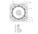
図21は、第1の従来技術における回転電機を示す側断面図であり、図22は、図21における回転電機の正断面図である。これらは、特許文献1に示されているものである。
この第1の従来技術における回転電機では、固定子鉄心112に装着された板状導体よりなる固定子コイル111の負荷側コイルエンド111eを、内周面と外周面を各々一円筒面上に形成するとともに、端面を一平面上に形成して、負荷側ブラケット115の溝部115eに密着させるようにしている。これにより、固定子コイル111において発生した熱を、負荷側ブラケット115を通して、効果的に放熱させ、冷却効果を向上させることができ、固定子コイル111の許容温度に対してより大きな通電を可能にして、定格出力を向上させることができる。
なお、図21および図22において、112cは固定子鉄心のティース部、113は第1のインシュレータ、114は第2のインシュレータ、116は反負荷側ブラケット、117は固定子コイル結線部、118は回転位置検出部、119は負荷側軸受、120は反負荷側軸受、121は永久磁石、122は保護テープ、123は回転子鉄心、124は回転軸である。
In the rotating electrical machine, the temperature of the stator coil rises due to heat loss due to driving, and the temperature of the rotating electrical machine rises. Particularly in an AC servo motor or the like, since a rotation detector such as an encoder provided on the non-load side of the motor is weak in temperature, it is necessary to suppress the temperature rise of the rotating electrical machine as much as possible.
Therefore, in conventional rotating electrical machines, for example, the heat generated by the stator coil mounted on the stator core is effectively radiated through the load-side bracket, and the cooling effect is improved. It is possible to increase the rated output by enabling greater energization with respect to the temperature (see, for example, Patent Document 1).
FIG. 21 is a side sectional view showing the rotating electrical machine in the first prior art, and FIG. 22 is a front sectional view of the rotating electrical machine in FIG. These are shown in
In the rotating electrical machine according to the first prior art, the load-side coil end 111e of the
21 and 22, 112 c is a teeth portion of the stator core, 113 is a first insulator, 114 is a second insulator, 116 is an anti-load side bracket, 117 is a stator coil connection portion, and 118 is a rotation. A position detection unit, 119 is a load side bearing, 120 is an anti-load side bearing, 121 is a permanent magnet, 122 is a protective tape, 123 is a rotor core, and 124 is a rotating shaft.
また、第2の従来技術における回転電機では、固定子コイルで発生した熱を熱伝導性が高い材料(例えば、特許文献2参照)や、放射性被膜(例えば、特許文献3参照)や、セラミック(例えば、特許文献4参照)を通して効果的に熱伝達し、冷却効果を向上させている。それにより、固定子コイルの許容温度に対してより大きな通電が可能となり、定格出力が向上している。 In the rotating electrical machine according to the second prior art, the heat generated in the stator coil is made of a material having high thermal conductivity (for example, see Patent Document 2), a radioactive coating (for example, see Patent Document 3), ceramic ( For example, the heat transfer is effectively performed through Patent Document 4) to improve the cooling effect. Thereby, larger energization is possible with respect to the allowable temperature of the stator coil, and the rated output is improved.
図23は上記第2の従来技術における回転電機を示す側断面図であり、特許文献2に示されているものである。
この第2の従来技術における回転電機では、フレーム141の内側に密着した固定子鉄心142と、前記固定子鉄心142に巻装した固定子コイル143のコイルエンド143eと前記フレーム141との間に熱伝導体149を充填固着するとともに、前記熱伝導体149を、セラミック粉末を混合した熱硬化性樹脂で形成して構成している。これにより、高い熱伝導性を得られるため、固定子コイル143で発生する熱をコイルエンド143eからこの熱伝導体149を経由してフレーム141に伝熱でき、冷却効果を向上することができる。なお、図23において、144はブラケット、145は軸受、146は回転軸、147は回転子、147aは永久磁石、147bはヨーク、147cはスリーブ、148はプレート、150は冷却液用通路である。
FIG. 23 is a side sectional view showing the rotating electrical machine in the second prior art, which is shown in
In the rotating electrical machine according to the second prior art, the
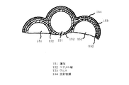
図24は第3の従来技術における回転電機の固定子コイルの一部を示す断面図であり、特許文献3に示されているものである。
この第3の従来技術における回転電機では、導体151の外側にエナメル層152がある通常のマグネットワイヤを巻回し、ワニス153により硬化させた後に、固定子コイルのコイルエンド部に対しセラミック遠赤外線、あるいは、遠赤外線の放射被膜154の塗布を行い、巻線からの熱放射を向上させ、回転電機の冷却効果を向上させるようにしている。
FIG. 24 is a cross-sectional view showing a part of a stator coil of a rotating electrical machine in the third prior art, which is shown in
In the rotating electrical machine according to the third prior art, a normal magnet wire having an
図25は第4の従来技術における回転電機を示す側断面図であり、特許文献4に示されているものである。
この第4の従来技術における回転電機では、固定子鉄心162に巻回した固定子コイル163のコイルエンド163eとフレーム161との間にリング状の熱伝導体169であるセラミックを挿入するとともに、前記コイルエンド163eと前記熱伝導体169との間に熱硬化性樹脂170を充填し固着して構成している。これにより、固定子コイル163で発生する熱を、コイルエンド163eから熱伝導体169であるセラミックを経由してフレーム161に伝熱でき、冷却効果を向上し、固定子コイル163の許容温度に対してより大きな通電を可能として、定格出力を向上させることができる。
In the rotating electrical machine according to the fourth prior art, a ceramic which is a ring-
しかしながら、このような従来の技術においては、次のような問題がある。
(1)第1の従来技術における回転電機は、固定子コイルにおいて発生した熱を、負荷側ブラケットを通して、効果的に放熱し、冷却効果を向上させているが、絶縁被膜を施された銅板をプレスで打ち抜いて製作された固定子コイルを用いているため高価である。
However, such a conventional technique has the following problems.
(1) The rotating electrical machine according to the first prior art effectively dissipates the heat generated in the stator coil through the load side bracket and improves the cooling effect. It is expensive because it uses a stator coil produced by punching with a press.
(2)第2の従来技術における回転電機は、セラミック粉末を混合した熱硬化性樹脂を経由して、効果的に放熱し、冷却効果を向上させているが、前記熱硬化性樹脂の熱伝導性が依然小さいため、冷却効果の向上には制限がある。 (2) The rotating electrical machine according to the second conventional technique effectively dissipates heat and improves the cooling effect via the thermosetting resin mixed with the ceramic powder, but the heat conduction of the thermosetting resin Since the property is still small, there is a limit to improving the cooling effect.
(3)第3の従来技術における回転電機の巻線は、熱放射性被膜から回転電機中に熱放射するため、熱伝導による冷却効果に比較して、効果が小さい。 (3) Since the winding of the rotating electrical machine in the third prior art radiates heat from the heat radiation coating into the rotating electrical machine, the effect is small compared to the cooling effect by heat conduction.
(4)第4の従来技術における回転電機は、熱伝導体であるセラミックを経由して効果的に放熱し、冷却効果を向上させているが、コイルエンドの表面に巻線による凸凹の空間が形成されるため、コイルエンドとフレームとの密着が不十分になることと、コイルエンドに熱伝導体であるセラミックのスペースが必要となり、回転電機を小型化できない。 (4) The rotating electrical machine according to the fourth prior art effectively dissipates heat through the ceramic, which is a heat conductor, and improves the cooling effect. However, there is an uneven space due to the winding on the surface of the coil end. As a result, the coil end and the frame are not sufficiently adhered to each other, and a ceramic space as a heat conductor is required at the coil end, and the rotating electrical machine cannot be reduced in size.
本発明は、このような問題点に鑑みてなされたものであり、安価で、絶縁性能を確保しながら、小型化でき、固定子コイルにおいて発生した熱を効果的に放熱して、冷却効果を向上し、固定子コイルの許容温度に対してより大きな通電を可能として、定格出力を格段に向上する回転電機を提供することを目的とするものである。 The present invention has been made in view of such problems, and is inexpensive, can be downsized while ensuring insulation performance, effectively dissipates heat generated in the stator coil, and has a cooling effect. It is an object of the present invention to provide a rotating electrical machine that can improve the rated output by improving the rated temperature and allowing larger energization with respect to the allowable temperature of the stator coil.
上記問題を解決するため、本発明は、次のように構成したものである。
請求項1に記載の回転電機の発明は、円筒状のフレームと、前記フレームの内周面に嵌合固着された固定子鉄心と、負荷側コイルエンドおよび反負荷側コイルエンドが前記固定子鉄心の回転軸方向の両端面から突出するように前記固定子鉄心に装着された、巻線からなる固定子コイルとを備えた固定子と、前記フレームの負荷側に設けられ、前記負荷側コイルエンドを挿入する溝が形成された負荷側ブラケットであって、前記負荷側コイルエンドの内周面、外周面、および端面のうち、少なくとも端面を含む1面以上が、空隙を介さずに絶縁体を介して前記溝の内面に密着した負荷側ブラケットと、前記フレームの反負荷側に設けられた反負荷側ブラケットと、前記負荷側ブラケットおよび前記反負荷側ブラケットに、負荷側軸受および反負荷側軸受を介して回転自在に支持された回転軸と、前記回転軸の外周面に取付けられた回転子と、を備え、前記1面以上の形状を、密着する前記溝の内面の形状と同じ形状にするように、前記負荷側コイルエンドの外面を加圧して成形し、前記負荷側ブラケットの溝にモールド樹脂またはワニスを入れたのち、前記負荷側コイルエンドの端面を、前記負荷側ブラケットの溝内に挿入し、前記負荷側コイルエンドが前記負荷側ブラケットの溝内に密着するように押し当てたまま、前記固定子と前記負荷側ブラケットを、モールド樹脂またはワニスで一体化したものである。
In order to solve the above problems, the present invention is configured as follows.
The invention of the rotating electrical machine according to
請求項2に記載の回転電機の発明は、前記負荷側ブラケットが、アルミ合金製であり、前記負荷側ブラケットの溝の内面には、セラミック製の被膜が形成されていることを特徴とするものである。 According to a second aspect of the present invention, the load-side bracket is made of an aluminum alloy, and a ceramic coating is formed on the inner surface of the groove of the load-side bracket. It is.
請求項3に記載の回転電機の発明は、前記固定子鉄心が、内周部に、スロットを形成する複数個のティース部を有し、前記ティース部に、内側が前記ティース部よりも軸方向に長く形成された固定子コイルを装着していることを特徴とするものである。 According to a third aspect of the present invention, the stator iron core has a plurality of teeth portions forming slots in the inner peripheral portion, and the inner side of the teeth portions is more axial than the teeth portions. A stator coil that is long is attached to the base plate.
請求項4に記載の回転電機の発明は、前記固定子鉄心が、内周部に、スロットを形成しない内周面を有するとともに、前記内周面に、セラミック製の被膜を介して固定子コイルを載置していることを特徴とするものである。 According to a fourth aspect of the present invention, the stator iron core has an inner peripheral surface that does not form a slot in the inner peripheral portion, and a stator coil via a ceramic coating on the inner peripheral surface. It is characterized by mounting.
請求項5に記載の回転電機の発明は、前記セラミック製の被膜が、前記固定子鉄心の内周面の、前記固定子コイルと接触する部分に形成されていることを特徴とするものである。
The invention of the rotating electrical machine according to
請求項7に記載の回転電機の発明は、円筒状のフレームと、前記フレームの内周面に嵌合固着された固定子鉄心と、負荷側コイルエンドおよび反負荷側コイルエンドが前記固定子鉄心の回転軸方向の両端面から突出するように固定子鉄心に装着された、巻線からなる固定子コイルとを備えた固定子と、前記フレームの負荷側に設けられ、前記負荷側コイルエンドを挿入する溝が形成された負荷側ブラケットであって、前記負荷側コイルエンドの内周面、外周面、および端面のうち、少なくとも端面を含む1面以上が、空隙を介さずに絶縁体を介して前記溝の内面に密着した負荷側ブラケットと、前記フレームの反負荷側に設けられた反負荷側ブラケットと、前記負荷側ブラケットおよび前記反負荷側ブラケットに、負荷側軸受および反負荷側軸受を介して回転自在に支持された回転軸と、前記回転軸の外周面に取付けられた回転子と、を備え、前記負荷側ブラケットは、セラミック製であり、前記1面以上の形状を、密着する前記溝の内面の形状と同じ形状にするように、前記負荷側コイルエンドの外面を加圧して成形し、前記負荷側ブラケットの溝にモールド樹脂またはワニスを入れたのち、前記負荷側コイルエンドの端面を、前記負荷側ブラケットの溝内に挿入し、前記負荷側コイルエンドが前記負荷側ブラケットの溝内に密着するように押し当てたまま、前記固定子と前記負荷側ブラケットを、モールド樹脂またはワニスで一体化したものである。 According to a seventh aspect of the present invention, there is provided a rotating electric machine comprising: a cylindrical frame; a stator core fitted and fixed to an inner peripheral surface of the frame; and a load-side coil end and an anti-load-side coil end. A stator having a stator coil composed of windings mounted on the stator core so as to protrude from both end surfaces of the rotation axis direction of the frame, and provided on the load side of the frame, A load-side bracket in which a groove to be inserted is formed, and at least one of the inner peripheral surface, outer peripheral surface, and end surface of the load-side coil end including the end surface is interposed via an insulator without a gap. A load side bracket closely attached to the inner surface of the groove, an antiload side bracket provided on the antiload side of the frame, a load side bearing and an antiload side on the load side bracket and the antiload side bracket A rotary shaft supported rotatably via a receiver, and a rotor attached to the outer peripheral surface of the rotary shaft, the load-side bracket is made of ceramic, and has a shape of one or more surfaces, After pressing and molding the outer surface of the load side coil end so as to have the same shape as that of the inner surface of the groove to be in close contact, and then putting mold resin or varnish into the groove of the load side bracket, the load side coil The end face of the end is inserted into the groove of the load side bracket, and the stator and the load side bracket are molded with the load side coil end pressed against the groove of the load side bracket. Integrated with resin or varnish .
請求項8に記載の回転電機の発明は、前記固定子コイルの、負荷側コイルエンドの内周面、外周面、および端面のうち、少なくとも端面を含む1面以上が、前記溝の形状に合わせて成形されていることを特徴とするものである。 According to an eighth aspect of the present invention, at least one of the stator coil including the end surface, the inner surface, the outer surface, and the end surface of the load-side coil end matches the shape of the groove. It is characterized by being molded.
請求項9に記載の回転電機の製造方法の発明は、円筒状のフレームと、前記フレームの内周面に嵌合固着された固定子鉄心と、負荷側コイルエンドが前記固定子鉄心の回転軸方向の両端面から突出するように固定子鉄心に装着された、巻線からなる固定子コイルとを備えた固定子と、前記フレームの負荷側に設けられた負荷側ブラケットと、前記フレームの反負荷側に設けられた反負荷側ブラケットと、前記負荷側ブラケットおよび前記反負荷側ブラケットに、負荷側軸受および反負荷側軸受を介して回転自在に支持された回転軸と、前記回転軸の外周面に取付けられた回転子と、を備えた回転電機の製造方法において、前記負荷側ブラケットの内面の、前記負荷側コイルエンドに対向する部位に、前記負荷側コイルエンドの内周面、外周面、および端面のうち、少なくとも端面を含む1面以上で密着する溝を形成し、前記1面以上の形状を、密着する前記溝の内面の形状と同じ形状にするように、前記負荷側コイルエンドの外面を加圧して成形し、前記負荷側ブラケットの溝にモールド樹脂またはワニスを入れたのち、前記負荷側コイルエンドの端面を、前記負荷側ブラケットの溝内に挿入し、前記負荷側コイルエンドが前記負荷側ブラケットの溝内に密着するように押し当てたまま、前記固定子と前記負荷側ブラケットを、モールド樹脂またはワニスで一体化したことを特徴とするものである。
The invention of the method for manufacturing a rotating electrical machine according to
請求項10に記載の回転電機の製造方法の発明は、前記固定子鉄心が、内周部に、スロットを形成しない内周面を有するとともに、前記内周面の、固定子コイルが載置される部分に、セラミック製の被膜を溶射して、固定子コイルを密着させ、前記負荷側コイルエンドの端面を、前記負荷側ブラケットの溝内に挿入し、前記負荷側コイルエンドが前記負荷側ブラケットの溝内に密着するように押し当てたまま、前記固定子と前記負荷側ブラケットを、モールド樹脂またはワニスで一体化することを特徴とするものである。 According to a tenth aspect of the present invention, there is provided a method of manufacturing a rotating electrical machine, wherein the stator core has an inner peripheral surface that does not form a slot in an inner peripheral portion, and a stator coil on the inner peripheral surface is mounted. A ceramic coating is thermally sprayed on the portion to be fixed, the stator coil is brought into close contact, the end surface of the load side coil end is inserted into the groove of the load side bracket, and the load side coil end is inserted into the load side bracket. The stator and the load side bracket are integrated with a mold resin or a varnish while being pressed so as to be in close contact with the groove.
請求項11に記載の回転電機の製造方法の発明は、前記負荷側ブラケットをアルミ合金製にするとともに、前記負荷側ブラケットの溝の内面に、セラミック製の被膜を溶射によって形成することを特徴とするものである。
The invention of the method for manufacturing a rotating electrical machine according to
請求項12に記載の回転電機の製造方法の発明は、前記負荷側ブラケットは、セラミック製であることを特徴とするものである。
The invention of the method for manufacturing a rotating electrical machine according to
本発明によれば、次のような効果がある。
(1)負荷側ブラケットに設けるリング状の溝の内面に、熱伝導性の高いセラミック製の被膜を形成すると、セラミック製の被膜の厚さにより、僅かなスペースによって、負荷側コイルエンドと前記負荷側ブラケットとの間の絶縁性能を十分に確保することができ、回転電機を小型化することができる。
また、前記負荷側コイルエンドを、前記負荷側ブラケットの溝に挿入し、前記負荷側コイルエンドの内周面、外周面、および端面のうち、少なくとも端面を含む1面以上を、前記セラミック製の被膜を介して溝の内面に密着させると、固定子コイルにおいて発生した熱を、外気あるいは取付ける装置本体と接する負荷側ブラケットに効果的に熱伝達することができ、速やかに回転電機外部に放熱して回転電機の冷却効果を向上させることができる。これにより、固定子コイルの許容温度に対してより大きな通電を可能にし、定格出力を格段に向上する回転電機を提供することができる。
The present invention has the following effects.
(1) to the inner surface of the ring-shaped groove provided on the load side bracket above, forming a high thermal conductivity ceramic coating Then, the thickness of the ceramic coating, a slight space, and the load side coil end Insulation performance with the load side bracket can be sufficiently secured, and the rotating electrical machine can be downsized.
The load side coil end is inserted into the groove of the load side bracket, and at least one of the inner peripheral surface, the outer peripheral surface, and the end surface of the load side coil end including the end surface is made of the ceramic. When through a film Ru is adhered to the inner surface of the groove, the heat generated in the stator coil, it is possible to effectively heat transfer to the load-side bracket in contact with the outside air or mounting apparatus main body, to quickly rotating electric machine external heat Thus, the cooling effect of the rotating electrical machine can be improved. As a result, it is possible to provide a rotating electrical machine capable of energizing more with respect to the allowable temperature of the stator coil and significantly improving the rated output.
(2)請求項2に記載の回転電機の発明によると、負荷側ブラケットをアルミ合金製とすることにより、前記負荷側ブラケットと熱伝導性の高いセラミック製の被膜との接合性を高くして、接触熱抵抗を小さくすることができる。これにより、固定子コイルにおいて発生した熱を、前記負荷側ブラケットにさらに効果的に熱伝達することができ、速やかに回転電機外部に放熱して回転電機の冷却効果を大きく向上させることができる。したがって、前記固定子コイルの許容温度に対してより大きな通電を可能にし、定格出力を格段に向上する回転電機を提供することができる。
(2) According to the invention of the rotating electrical machine according to
(3)請求項3に記載の回転電機の発明によると、固定子鉄心が、内周部に、スロットを形成する複数個のティース部を有し、前記ティース部に、内側が前記ティース部よりも軸方向に長く形成された固定子コイルを装着しているので、前記固定子コイルの内側と前記ティース部の間に空間が形成され、前記固定子鉄心をフレームに固定し、前記フレームを負荷側ブラケットに固定した後も、あるいは、前記フレームと前記固定子鉄心を前記負荷側ブラケットに固定した後も、前記固定子コイルを軸方向に動かすことができる。それにより、前記固定子鉄心を前記負荷側ブラケットに固定したのち、固定子は、前記固定子コイルを軸方向に動かして、前記負荷側コイルエンドの端面を前記負荷側ブラケットの溝に密着するように押し当てたまま、前記固定子と前記負荷側ブラケットをモールド樹脂またはワニスで一体化することができ、前記固定子コイルにおいて発生した熱を、外気あるいは取付ける装置本体と接する前記負荷側ブラケットに効果的に熱伝達することができ、速やかに回転電機外部に放熱して前記回転電機の冷却効果を向上させることができる。したがって、前記固定子コイルの許容温度に対してより大きな通電を可能にし、定格出力を格段に向上する回転電機を提供することができる。
(3) According to the invention of the rotating electrical machine according to
請求項4および5に記載の回転電機の発明によると、固定子コイルにおいて発生した熱を、負荷側コイルエンドから、外気あるいは取付ける装置本体と接する負荷側ブラケットに効果的に熱伝達することができるだけでなく、前記固定子コイルから熱伝達された固定子鉄心からも熱伝導性の高いセラミック製の被膜を通して、フレームに効果的に熱伝達されるので、さらに速やかに、回転電機外部に放熱して前記回転電機の冷却効果を向上させることができる。したがって、前記固定子コイルの許容温度に対してより大きな通電を可能にし、定格出力を格段に向上する回転電機を提供することができる。 According to the rotary electric machine of the present invention, the heat generated in the stator coil can be effectively transferred from the load side coil end to the outside air or the load side bracket in contact with the apparatus main body to be attached. In addition, heat is effectively transferred to the frame through the ceramic coating with high thermal conductivity from the stator core that is transferred from the stator coil. The cooling effect of the rotating electrical machine can be improved. Therefore, it is possible to provide a rotating electrical machine that allows greater energization with respect to the allowable temperature of the stator coil and that significantly improves the rated output.
負荷側ブラケットをセラミック製とすると、絶縁性能を高くするとともに、熱伝導性を高くすることができ、スペースをとる絶縁体を省略して、負荷側コイルエンドと前記負荷側ブラケットとの間の絶縁性能を確保することができる。これにより、回転電機を小型化することができるとともに、前記固定子コイルにおいて発生した熱を、外気あるいは取付ける装置本体と接する前記負荷側ブラケットに効果的に熱伝達することができ、速やかに回転電機外部に放熱して回転電機の冷却効果を向上させることができる。したがって、前記固定子コイルの許容温度に対してより大きな通電を可能にし、定格出力を格段に向上する回転電機を提供することができる。 When the load-side bracket and ceramic, as well as high insulation performance, it is possible to increase the thermal conductivity, skip insulator take up space, between the load-side bracket and the load-side coil end Insulation performance can be ensured. As a result, the rotating electrical machine can be reduced in size, and the heat generated in the stator coil can be effectively transferred to the load side bracket in contact with the outside air or the device main body to be attached, and the rotating electrical machine can be quickly The cooling effect of the rotating electric machine can be improved by radiating heat to the outside. Therefore, it is possible to provide a rotating electrical machine that allows greater energization with respect to the allowable temperature of the stator coil and that significantly improves the rated output.
請求項7に記載の回転電機の発明によると、固定子コイルは、負荷側コイルエンドの内周面、外周面、および端面のうち、少なくとも端面を含む1面以上を成形しており、一般的な丸線または平角線によって製作されるので、極めて安価となる。また、固定子は、前記負荷側コイルエンドの端面を、負荷側ブラケットの溝に密着するように押し当てたまま、固定子と前記負荷側ブラケットをモールド樹脂またはワニスで一体化することができ、前記固定子コイルにおいて発生した熱を、外気あるいは取付ける装置本体と接する前記負荷側ブラケットに効果的に熱伝達することができ、速やかに回転電機外部に放熱して前記回転電機の冷却効果を向上させることができる。したがって、前記固定子コイルの許容温度に対してより大きな通電を可能にし、定格出力を格段に向上する回転電機を提供することができる。 According to the rotating electrical machine of the seventh aspect of the invention, the stator coil is formed of one or more surfaces including at least the end surface among the inner peripheral surface, the outer peripheral surface, and the end surface of the load side coil end. Since it is manufactured by a round wire or a rectangular wire, it is extremely inexpensive. Further, the stator can be integrated with the mold resin or varnish while the end surface of the load side coil end is pressed against the groove of the load side bracket so that the stator and the load side bracket are in close contact with each other. The heat generated in the stator coil can be effectively transferred to the load side bracket in contact with the outside air or the apparatus main body to be attached, and quickly radiates heat to the outside of the rotating electrical machine to improve the cooling effect of the rotating electrical machine. be able to. Therefore, it is possible to provide a rotating electrical machine that allows greater energization with respect to the allowable temperature of the stator coil and that significantly improves the rated output.
負荷側ブラケットの溝に、セラミック製の被膜を形成するか、あるいは前記負荷側ブラケットをセラミック製で構成すると、固定子は、負荷側コイルエンドの端面を前記負荷側ブラケットの溝に密着するように押し当てたまま、前記固定子と前記負荷側ブラケットをモールド樹脂またはワニスにて一体化することによって、効果的に、かつ確実に、高い熱伝達性を得ることができるとともに、高い絶縁性を得ることができる。 The groove of the load-side bracket, or configured to form a ceramic coating, or the load-side bracket made of ceramic Then, the stator, so as to contact the end face of the load-side coil end in the groove of the load-side bracket By integrating the stator and the load-side bracket with a mold resin or varnish while being pressed against each other, high heat transfer can be obtained effectively and reliably, and high insulation is achieved. Can be obtained.
請求項10に記載の回転電機の発明によると、負荷側コイルエンドと負荷側ブラケットの溝の間に、モールド樹脂またはワニスを入れるので、前記負荷側コイルエンドと前記負荷側ブラケットの溝との間に、モールド樹脂またはワニスを確実に充填することができ、固定子コイルの相間の絶縁性能を確実に確保することができる。 According to the rotating electrical machine of the tenth aspect, since the molding resin or varnish is put between the load side coil end and the groove of the load side bracket, the gap between the load side coil end and the groove of the load side bracket is inserted. In addition, the mold resin or varnish can be reliably filled, and the insulation performance between the phases of the stator coil can be ensured.
請求項11に記載の回転電機の製造方法の発明によると、固定子鉄心の内周面に、セラミック製の被膜を溶射によって形成するので、被膜形成の位置精度を高めることができるとともに、被膜の厚さも変動が極めて少なく安定した被膜形成を行なうことができ、絶縁性と熱伝達性を高めることができる。
According to the invention of the manufacturing method of a rotating electrical machine according to
請求項12に記載の回転電機製造方法の発明によると、負荷側ブラケットをアルミ合金製とし、セラミック製の被膜を溶射によって形成するので、前記負荷側ブラケットと前記セラミック製の被膜との接合性を高くすることができ、接触熱抵抗を小さくすることができる。それにより、固定子コイルにおいて発生した熱を、外気あるいは取付ける装置本体と接する前記負荷側ブラケットに効果的に熱伝達することができ、速やかに回転電機外部に放熱して前記回転電機の冷却効果を向上させることができる。したがって、前記固定子コイルの許容温度に対してより大きな通電を可能にし、定格出力を格段に向上する回転電機を提供することができる。
According to the invention of the rotating electrical machine manufacturing method according to
巻線からなる固定子コイルの負荷側コイルエンドの内周面、外周面、および端面のうち、少なくとも端面を含む1面以上を、負荷側ブラケットに形成した溝の形状に合わせて成形すると、前記負荷側コイルエンドの内周面、外周面、および端面のうち、少なくとも端面を含む1面と、前記負荷側ブラケットの溝の内面との密着度を高めることができる。それにより、前記負荷側コイルエンドから前記負荷側ブラケットへの熱の伝達をさらに良好にすることができる。 The inner peripheral surface of the load-side coil end of the stator coil made winding peripheral surface, and out of the end surface, over one surface including at least the end face, when molded according to the shape of the groove formed on the load side bracket, Of the inner peripheral surface, outer peripheral surface, and end surface of the load side coil end, the degree of adhesion between at least one surface including the end surface and the inner surface of the groove of the load side bracket can be increased. Thereby, the heat transfer from the load side coil end to the load side bracket can be further improved.
以下、本発明の実施の形態について、図を参照して説明する。 Hereinafter, embodiments of the present invention will be described with reference to the drawings.
図1は、本発明の第1の実施例における回転電機を示す分解状態の斜視図である。
図1において、回転電機1は、フレーム5や反負荷側ブラケット7、固定子コイル12を有する固定子4と、負荷側ブラケット6を備えている。なお、図2において示される回転軸2を有する円筒形の回転子3は図示していない。
前記固定子コイル12の負荷側コイルエンド12aは、内周面12aaと外周面12abが各々一円筒面上に形成され、端面12acが一平面上に形成されている。前記負荷側ブラケット6は前記負荷側コイルエンド12aと前記負荷側コイルエンド12aの内周面12aa、外周面12ab、および、端面12acで密着する凹部状の溝6aを有し、前記溝6aには、セラミック製の被膜6bが形成されている。前記回転電機1の組立状態では、前記固定子4は、前記負荷側コイルエンド12aの端面12acを前記溝6aに密着するように押し当てたまま、前記固定子4と前記負荷側ブラケット6をモールド樹脂14にて一体化してなる。
前記固定子4は、熱伝導性の高い前記セラミック製の被膜6bを介して、前記負荷側コイルエンド12aの端面12acを前記溝6aに密着するように押し当てたまま、前記固定子4と前記負荷側ブラケット6を前記モールド樹脂14にて一体化してなる。そのため、前記固定子コイル12において発生した熱を効果的に放熱して、冷却効果を向上し、前記固定子コイル12の許容温度に対してより大きな通電を可能として、定格出力を格段に向上することができる。
FIG. 1 is an exploded perspective view showing a rotating electrical machine according to a first embodiment of the present invention.
In FIG. 1, the rotating
The load
While the
図2は、前記回転電機を示す側断面図である。
図2において、回転電機1は、埋込磁石型同期電動機であり、回転軸2を有する円筒形の回転子3と、固定子4とを備え、前記固定子4はフレーム5の内周に保持され、前記フレーム5は、負荷側に設置された負荷側ブラケット6に反負荷側ブラケット7とともに、図示しないボルトで締結され、組立されている。前記回転子3は、前記回転軸2に設置された負荷側軸受8と反負荷側軸受9を介して、前記負荷側ブラケット6と前記反負荷側ブラケット7に回転自在に保持され、前記回転軸2の反負荷側には、回転位置検出のためのエンコーダ部10が設置されている。
前記固定子4は、固定子鉄心11のティース部11aに絶縁紙16を装着して絶縁処理を行い、絶縁被膜を有する巻線を分布巻で巻回したのち、前記ティース部11aに装着して固定子コイル12とし、前記固定子コイル12の負荷側コイルエンド12aは、内周面12aaと外周面12abが各々一円筒面上に形成され、端面12acが一平面上に形成されている。前記固定子コイル12の反負荷側コイルエンド12bは近傍の結線部13において結線されている。前記負荷側ブラケット6は前記負荷側コイルエンド12aと前記負荷側コイルエンド12aの内周面12aa、外周面12ab、および、端面12acで密着する溝6aを有し、前記溝6aには、セラミック製の被膜6bが形成されている。前記固定子4は、前記負荷側コイルエンド12aの端面12acを前記溝6aに密着するように押し当てたまま、前記固定子4と前記負荷側ブラケット6をモールド樹脂14にて一体化している。
前記固定子4は、熱伝導性の高い前記セラミック製の被膜6bを介して、前記負荷側コイルエンド12aの端面12acを前記溝6aに密着するように押し当てたまま、前記固定子4と前記負荷側ブラケット6を前記モールド樹脂14にて一体化している。そのため、固定子コイル12において発生した熱を効果的に放熱している。
FIG. 2 is a sectional side view showing the rotating electrical machine.
In FIG. 2, the rotating
The
While the
図3は、前記回転電機を示す正断面図である。
図3において、回転軸2を有する円筒形の回転子3は、前記回転子3の内部に永久磁石15を埋設した埋込磁石型回転子である。固定子4は、固定子鉄心11のティース部11aに絶縁紙16を装着して絶縁処理を行い、絶縁被膜を有する巻線を分布巻で巻回したのち、前記ティース部11aに装着して固定子コイル12とし、前記フレーム5の内周に保持されている。
FIG. 3 is a front sectional view showing the rotating electric machine.
In FIG. 3, a
図4は、前記回転電機の前記負荷側コイルエンドを示す拡大断面図である。
図4において、前記セラミック製の被膜6bは前記溝6aの全体に形成されていて、前記負荷側コイルエンド12aと前記負荷側ブラケット6との間の、絶縁性能を確保している。前記セラミック製の被膜6bの厚さは、絶縁性能を確保することができる最小の厚さとしている。ここでは、0.3〜0.5mmとしている。
前記溝6aには、前記セラミック製の被膜6bが形成されているので、前記セラミック製の被膜6bの厚さによって、前記負荷側コイルエンド12aと前記負荷側ブラケット6との間の、絶縁性能を確保しながら、回転電機を小型化でき、また、前記固定子4は、熱伝導性の高い前記セラミック製の被膜6bを介して、前記負荷側コイルエンド12aの端面12acを前記溝6aに密着するように押し当てたまま、前記固定子4と前記負荷側ブラケット6を前記モールド樹脂14で一体化している。そのため、前記固定子コイル12において発生した熱を効果的に放熱して、冷却効果を向上し、前記固定子コイル12の許容温度に対してより大きな通電を可能として、定格出力を格段に向上することができる。
FIG. 4 is an enlarged cross-sectional view showing the load side coil end of the rotating electrical machine.
In FIG. 4, the
Since the
図5は、前記回転電機における固定子コイルと負荷側ブラケットとの密着された状態を示す拡大断面図である。
前記負荷側コイルエンド12aの端面12acを、前記溝6aに密着するように押し当てたまま、前記固定子4と前記負荷側ブラケット6を、前記モールド樹脂14で一体化している。なお、図5において、12aaは負荷側コイルエンド12aの内周面を示している。
図5において、前記負荷側コイルエンド12aは、加圧して外形状を成形されるので、凹凸の少ない平面形状を形成させることができる。しかし、巻線を巻回しているので多少の凹凸は生じるため、前記負荷側コイルエンド12aと前記溝6aとの間に巻線による凸凹の空間12cが形成され、前記溝6aに沿って、前記固定子コイル12の相間で沿面放電が生じて短絡する恐れがある。そのため、前記固定子4は、前記固定子4と前記負荷側ブラケット6を前記モールド樹脂14で一体化することによって、前記空間12cに前記モールド樹脂14を充填することができ、相間で沿面放電が生じて短絡する恐れが小さくなり、前記固定子コイル12の相間の絶縁性能を確保することができる。
本第1の実施例は、コイルとして丸線を使用しているが、平角線を使用した場合でも平角線の角Rなどにより多少の凹凸は生じる。また、低電圧の回転電機については、コイルの絶縁皮膜のみで、固定子4と負荷側ブラケット6をモールド樹脂14またはワニスにて一体化して、前記空間を残しても問題はない。
本発明の第1の実施例の回転電機が従来技術と異なる部分は、負荷側ブラケット6の溝6aに、セラミック製の被膜が形成されている点である。
FIG. 5 is an enlarged cross-sectional view showing a state in which the stator coil and the load side bracket are in close contact with each other in the rotating electric machine.
The
In FIG. 5, the load
In the first embodiment, a round wire is used as the coil. However, even when a flat wire is used, some unevenness occurs due to the angle R of the flat wire. For a low-voltage rotating electrical machine, there is no problem even if the
The rotating electric machine according to the first embodiment of the present invention is different from the prior art in that a ceramic film is formed in the
図6は、前記回転電機の前記負荷側ブラケットの製造方法を示す説明図である。
図6において、前記負荷側ブラケット6はアルミ合金製であり、前記負荷側ブラケット6は前記負荷側コイルエンド12aと前記負荷側コイルエンド12aの内周面12aa、外周面12ab、および、端面12acで密着する溝6aを有し、前記溝6aには、セラミック製の被膜6bが形成される。前記セラミック製の被膜6bは溶射ノズル17による溶射によって、前記溝6aの全体に形成される。
セラミックの種類は、アルミナ、窒化アルミニウムが望ましい。前記セラミック製の被膜6bは絶縁性能が高く、熱伝導性が高い。また、前記セラミック製の被膜6bは溶射によって形成されるので、前記負荷側ブラケット6と前記セラミック製の被膜6bとの接合性を高くすることができ、接触熱抵抗を小さくすることができ、前記固定子コイル12において発生した熱を効果的に放熱することができる。
FIG. 6 is an explanatory view showing a method for manufacturing the load side bracket of the rotating electrical machine.
In FIG. 6, the load-
The ceramic type is preferably alumina or aluminum nitride. The
図7は、前記回転電機の前記固定子の製造方法を示す図であり、(a)は、成形前の前記固定子4であり、(b)は、成形後の前記固定子4である。
図7において、前記固定子4は、固定子鉄心11のティース部11aに絶縁紙16を装着して絶縁処理を行い、絶縁被膜を有する巻線を分布巻で巻回したのち、前記ティース部11aに装着して固定子コイル12とされる。前記固定子コイル12の前記負荷側コイルエンド12aは、成形冶具18で加圧して外形状を成形され、内周面12aaと外周面12abが各々一円筒面上に形成され、端面12acが一平面上に形成される。
前記固定子コイル12は、一般的な巻線である丸線によって製作されるので、安価である。前記負荷側コイルエンド12aは前記成形冶具18で加圧して外形状を成形されるので、凹凸の少ない平面形状を形成され、外形状を精度良く仕上げられる。そのため、前記負荷側コイルエンド12aは凹凸の少ない平面形状を形成させることができる。
前記固定子コイル12において発生した熱を、負荷側ブラケットを通して放熱するため、反負荷側コイルエンド12bは、外形状を成形されない。
FIG. 7 is a diagram illustrating a method for manufacturing the stator of the rotating electrical machine, where (a) is the
In FIG. 7, the
Since the
Since the heat generated in the
図8は、前記回転電機の前記固定子の製造方法を示す説明図である。
図8において、前記固定子4は、前記溝6aに前記モールド樹脂14を入れたのち、前記負荷側コイルエンド12aの端面12acを前記溝6aに密着するように押し当てたまま、さらに、前記固定子4と前記負荷側ブラケット6を前記モールド樹脂14にて一体化してなる。
前記負荷側コイルエンド12aは、前記固定子鉄心11からの突き出し長さを前記溝6aの軸方向長さと同じ、あるいは、長く形成されていて、前記負荷側コイルエンド12aの端面12acを前記溝6aに密着するように押し当てると、前記コイルエンド12aの前記端面12acを前記溝6aに密着させることができる。さらに、前記負荷側コイルエンド12aは、金型で加圧して外形状を成形されるので、前記負荷側コイルエンド12aの内周面12aaと外周面12abが各々一円筒面上に形成され、端面12acが一平面上に形成されて、前記負荷側コイルエンド12aの内周面12aa、および、外周面12abを前記溝6aに密着させることができる。前記負荷側コイルエンド12aと前記溝6aは、前記負荷側コイルエンド12aの内周面12aa、前記外周面12ab、および、前記端面12acの、少なくとも前記端面12acを含む1面以上で密着されていてもよい。
従来の回転電機は、前記固定子4と前記負荷側ブラケット6を前記モールド樹脂14にて一体化してなり、前記負荷側コイルエンド12aと前記溝6aとの間の巻線による凸凹の空間に前記モールド樹脂14を充填して一体化される。しかし、前記空間は、隙間が小さく、前記モールド樹脂14を充填するのに注意が必要である。さらに、前記モールド樹脂14に熱伝導体粉末などを混入した場合、粘度が高くなり、前記固定子4と前記負荷側ブラケット6を前記モールド樹脂14にて一体化してなる場合に、モータ全体に注入できない場合がある。本第1の実施例では、前記溝6aに前記モールド樹脂14を入れたのち、前記負荷側コイルエンド12aの端面12acを前記溝6aに密着するように押し当てるので、前記空間に、前記モールド樹脂14を確実に充填することができ、前記固定子コイル12の相間で沿面放電が生じて短絡する恐れが小さくなり、前記固定子コイル12の相間の絶縁を確保することができる。
前記固定子4は、前記負荷側コイルエンド12aの端面12acを前記溝6aに密着するように押し当てたまま、図示しない前記フレーム5を前記固定子4の外周に、図示しないボルトで締結され、組立されるので、前記負荷側コイルエンド12aの端面12acを前記溝6aに密着するように押し当てたまま、前記フレーム5を前記負荷側ブラケット6に密着させることができ、前記固定子コイル12において発生した熱を前記負荷側コイルエンド12aを通して前記ブラケット6より、効果的に放熱するとともに、前記固定子コイル12において発生した熱を前記固定子鉄心11と前記フレーム5を通して前記ブラケット6より、効果的に放熱することができる。
FIG. 8 is an explanatory view showing a method of manufacturing the stator of the rotating electrical machine.
In FIG. 8, after the
The load
In the conventional rotating electrical machine, the
The
図9は、以上説明した前記固定子を製造する処理手順を示すフローチャートである。
本発明の第1の実施例の回転電機の製造方法が従来技術と異なる部分は、前記負荷側コイルエンド12aの端面12acを前記溝6aに密着するように押し当てる部分と、前記溝6aに前記モールド樹脂14を入れたのち、前記負荷側コイルエンド12aの端面12acを前記溝6aに密着するように押し当てたまま、さらに、前記固定子4と前記負荷側ブラケット6を前記モールド樹脂14で一体化している部分である。
FIG. 9 is a flowchart showing a processing procedure for manufacturing the stator described above.
The part of the rotating electrical machine manufacturing method of the first embodiment of the present invention different from the prior art is that the end surface 12ac of the load
図10は、本発明の第2の実施例における回転電機を示す負荷側コイルエンド部分の拡大断面図である。
図10において、固定子24は、固定子鉄心31のティース部31aに絶縁紙36を装着して絶縁処理を行い、絶縁被膜を有する巻線を分布巻で巻回したのち、前記ティース部31aに装着して固定子コイルとし、固定子コイル32の負荷側コイルエンド32aは内周面32aaと外周面32abが各々一円筒面上に形成され、端面32acが一平面上に形成されている。負荷側ブラケット26はセラミック製にて形成され、前記負荷側コイルエンド32aと前記負荷側コイルエンド32aの内周面32aa、外周面32ab、および、端面32acで密着する溝26aを有している。前記固定子24は、前記負荷側コイルエンド32aの端面32acを前記溝26aに密着するように押し当てたまま、前記固定子24と前記負荷側ブラケット26をモールド樹脂34にて一体化してなる。
前記負荷側ブラケット26はセラミック製にて形成されていて、絶縁性能が高く、熱伝導性が高いので、絶縁体を省略して、前記負荷側コイルエンド32aと前記溝6aの間の、絶縁性能を確保しながら、回転電機を小型化でき、また、前記固定子24は、前記負荷側コイルエンド32aの端面32acを前記溝26aに密着するように押し当てたまま、前記固定子24と前記負荷側ブラケット26をモールド樹脂34にて一体化してなることができ、前記固定子コイル32において発生した熱を効果的に放熱して、冷却効果を向上し、前記固定子コイル32の許容温度に対してより大きな通電を可能として、定格出力を格段に向上する回転電機を提供することができる。
本発明の第2の実施例の回転電機が従来技術と異なる部分は、負荷側ブラケットがセラミック製である部分である。
FIG. 10 is an enlarged cross-sectional view of a load side coil end portion showing a rotating electrical machine in the second embodiment of the present invention.
In FIG. 10, the
The
The portion of the rotating electric machine according to the second embodiment of the present invention that is different from the prior art is a portion in which the load side bracket is made of ceramic.
図11は、本発明の第3の実施例における回転電機を示す側断面図である。
図11において、回転電機41は、固定子鉄心51にスロットのない表面磁石型同期電動機であり、回転軸42を有する円筒形の回転子43と、固定子44とを備え、前記固定子44は、フレームを一体にした負荷側に設置された負荷側ブラケット46の内周に保持され、前記負荷側ブラケット46は反負荷側ブラケット47とともに、図示しないボルトで締結され、組立されている。前記回転子43は、回転軸42に設置された負荷側軸受48と反負荷側軸受49を介して、前記負荷側ブラケット46と前記反負荷側ブラケット47に回転自在に保持され、前記回転軸42の反負荷側には、回転位置検出のためのエンコーダ部50が設置されている。
前記固定子44は、絶縁被膜を持つ巻線を巻回したのち、金型で加圧して外形状を成形して、接着した空芯コイルを、スロットがない固定子鉄心51の内周に装着して固定子コイル52とし、前記固定子コイル52の負荷側コイルエンド52aは内周面52aaと外周面52abが各々一円筒面上に形成され、端面52acが一平面上に形成されている。前記固定子コイル52の反負荷側コイルエンド52bは近傍の結線部53において結線されている。前記負荷側ブラケット46は前記負荷側コイルエンド52aと前記負荷側コイルエンド52aの内周面52aa、外周面52ab、および、端面52acで密着する溝46aを有し、前記溝46aと、前記固定子鉄心51の前記固定子コイル52に接触する部分51bには、セラミック製の被膜46bが形成されている。前記固定子44は、前記負荷側コイルエンド52aの端面52acを前記溝46aに密着するように押し当てたまま、前記固定子44と前記負荷側ブラケット46を前記モールド樹脂54にて一体化してなる。そのため、前記固定子コイル52において発生した熱を効果的に放熱して、冷却効果が向上し、固定子コイルの許容温度に対してより大きな通電が可能となり、定格出力を格段に向上することができる。
FIG. 11 is a side sectional view showing a rotating electrical machine in the third embodiment of the present invention.
In FIG. 11, a rotating
The
図12は、前記回転電機を示す径側断面図である。
図12において、回転軸42を有する円筒形の回転子43は、前記回転子43の外部に永久磁石55を装着した表面磁石型回転子である。固定子44は、絶縁被膜を持つ巻線を巻回したのち、金型で加圧して外形状を成形して、接着した空芯コイルを、固定子鉄心51の内周に装着して固定子コイル52とし、フレームを一体にした負荷側ブラケット46の内周に保持されている。
FIG. 12 is a radial side sectional view showing the rotating electrical machine.
In FIG. 12, a
図13は、前記回転電機を示す側断面図のうち、前記負荷側コイルエンド52aを示す拡大図である。
図13において、前記セラミック製の被膜46bは、前記溝46aと、前記子鉄心51の前記固定子コイル52の接触する部分51bの全体に形成されていて、前記負荷側コイルエンド52aと前記負荷側ブラケット46、および、前記固定子鉄心51との間の、絶縁性能を確保している。前記セラミック製の被膜46bの厚さは、絶縁性能を確保することができる最小の厚さとしている。ここでは、0.3〜0.5mmとしている。
前記溝46aと、前記固定子鉄心51の前記固定子コイル52の接触する部分51bの前記セラミック製の被膜46bの厚さによって、前記固定子コイル52と前記負荷側ブラケット46、および、前記固定子鉄心51との、絶縁性能を確保しながら、回転電機を小型化でき、また、前記固定子44は、熱伝導性の高い前記セラミック製の被膜46bを介して、前記負荷側コイルエンド52aの端面52acを前記溝46aに密着するように押し当てたまま、前記固定子44と前記負荷側ブラケット46を前記モールド樹脂54にて一体化してなることができ、前記固定子コイル52において発生した熱を効果的に放熱して、冷却効果を向上し、固定子コイルの許容温度に対してより大きな通電を可能として、定格出力を格段に向上することができる。
本発明の第3の実施例の回転電機が従来技術と異なる部分は、固定子鉄心の固定子コイルの接触する部分にセラミック製の被膜が形成されている回転電機である部分である。
FIG. 13 is an enlarged view showing the load
In FIG. 13, the
Depending on the thickness of the
The part of the third embodiment of the present invention in which the rotating electrical machine is different from the prior art is a rotating electrical machine in which a ceramic coating is formed on the portion of the stator core that contacts the stator coil.
図14は、前記回転電機の前記固定子の製造方法を示す説明図である。
図14において、前記固定子鉄心51は、フレームを一体にした前記負荷側ブラケット46の内周に保持されて、前記負荷側ブラケット46とともに、図示しないボルトで締結され、組立される。前記負荷側ブラケット46は前記負荷側コイルエンド52aと前記負荷側コイルエンド52aの内周面52aa、外周面52ab、および、端面52acで密着する溝46aを有し、前記溝46aと、前記固定子鉄心51の前記固定子コイル52に接触する部分51bには、セラミック製の被膜46bが形成される。前記セラミック製の被膜46bは溶射ノズル57による溶射によって前記固定子コイル52に接触する部分51bの全体に形成される。
前記溝46aにセラミック製の被膜46bが形成された前記負荷側ブラケット46に、前記固定子鉄心51を、図示しないボルトで締結され、組立され、前記固定子鉄心51の前記固定子コイル52に接触する部分51bにセラミック製の被膜46bを溶射する。前記固定子鉄心51を前記負荷側ブラケット46の内周に保持されて、前記固定子鉄心51の前記固定子コイル52に接触する部分51bにセラミック製の被膜46bを溶射することによって、絶縁処理を行っている。また、前記固定子鉄心51の絶縁処理と前記負荷側ブラケット46の溶射を同じ工程で行う場合は、前記固定子鉄心51の絶縁処理を効果的に行なうことができる。
前記負荷側ブラケット46において、フレームが別に存在する場合は、前記固定子鉄心51は、フレームの内周に保持され、前記固定子鉄心51の前記固定子コイル52に接触する部分51bにセラミック製の被膜46bを溶射して、前記溝46aにセラミック製の被膜46bが形成された前記負荷側ブラケット46に、図示しないボルトで締結され、組立される。
FIG. 14 is an explanatory view showing a method for manufacturing the stator of the rotating electrical machine.
In FIG. 14, the
The
In the
図15は、前記回転電機の前記固定子の製造方法を示す説明図である。
図15において、前記固定子コイル52と前記負荷側ブラケット46は、モールド冶具56に取り付けて、前記固定子44は、前記負荷側コイルエンド52aの端面52acを前記溝46aに密着するように押し当てたまま、前記固定子44と前記負荷側ブラケット46を前記モールド樹脂54にて一体化している。
前記モールド冶具と前記固定子コイル52との間は、前記固定子コイル52の絶縁性能を確保する隙間があり、セラミック製の被膜46bと前記固定子コイル52との間は、巻線による凸凹の空間がある。前記モールド樹脂54は、前記固定子コイル52の絶縁性能を確保する隙間と前記巻線による凸凹の空間に充填されて、前記固定子コイル52をモールドするので、前記固定子44は、前記固定子44と前記負荷側ブラケット46を前記モールド樹脂54で一体化している。前記溝46aと、前記固定子鉄心51に前記固定子コイル52の接触する部分51bの前記セラミック製の被膜46bの厚さによって、前記固定子コイル52と前記負荷側ブラケット46、および、前記固定子鉄心51との、絶縁性能を確保しながら、回転電機を小型化でき、また、前記固定子コイル52と前記負荷側ブラケット46、および、前記固定子鉄心51は、熱伝導性の高い前記セラミック製の被膜46bを介して、前記固定子44は、前記負荷側コイルエンド52aの端面52acを前記溝46aに密着するように押し当てたまま、前記固定子44と前記負荷側ブラケット46を前記モールド樹脂54とで一体化することができる。
FIG. 15 is an explanatory view showing a method for manufacturing the stator of the rotating electrical machine.
In FIG. 15, the
There is a gap between the mold jig and the
図16は、以上説明した前記固定子を製造する処理手順を示すフローチャートである。
本発明の第3の実施例の回転電機の製造方法が従来技術と異なる部分は、前記負荷側コイルエンド52aの端面52acを前記溝46aに密着するように押し当てたまま、前記固定子44と前記負荷側ブラケット46を、前記モールド樹脂54にて一体化している部分である。
FIG. 16 is a flowchart showing a processing procedure for manufacturing the stator described above.
The part of the third embodiment of the present invention in which the rotating electrical machine is manufactured differently from the prior art is that the end face 52ac of the load
図17は、本発明の第4の実施例における回転電機を示す側断面図である。
図17において、回転電機61は、埋込磁石型同期電動機であり、回転軸62を有する円筒形の回転子63と、固定子64とを備え、前記固定子64は負荷側に設置された負荷側ブラケット66の内周に保持され、前記負荷側ブラケット66に反負荷側ブラケット67とともに、図示しないボルトで締結され、組立されている。前記回転子63は、回転軸62に設置された負荷側軸受68と反負荷側軸受69を介して、前記負荷側ブラケット66と前記反負荷側ブラケット67に回転自在に保持され、前記回転軸42の反負荷側には、回転位置検出のためのエンコーダ部70が設置されている。
前記固定子64は、固定子鉄心71のティース部71aに絶縁紙76を装着して絶縁処理を行い、絶縁被膜を持つ巻線を巻回したのち、金型で加圧して外形状を成形して、接着した空芯コイルを、前記ティース部71aに装着して固定子コイル72としている。前記固定子コイル72の内側は、前記ティース部71aよりも軸方向に大きく形成され、前記固定子コイル72の負荷側コイルエンド72aは、内周面72aaと外周面72abが各々一円筒面上に形成され、端面72acが一円錐面上に形成され、前記負荷側コイルエンド72aを前記モールド樹脂74にて一体化してなる。また、前記固定子コイルの外形状にセラミック製の被膜72cが形成されている。前記固定子コイル52の反負荷側コイルエンド52bは近傍の結線部53において結線されている。前記負荷側ブラケット66は前記負荷側コイルエンド72aと前記負荷側コイルエンド72aの内周面72aa、外周面72ab、および、端面72acで密着する溝66aが形成されている。前記固定子64は、前記負荷側コイルエンド72aの端面72acを前記溝66aに密着するように押し当てたまま、前記固定子64と前記負荷側ブラケット66を前記モールド樹脂54にて一体化してなる。前記セラミック製の被膜72cは前記固定子コイル72の全体に形成されていて、前記固定子コイル72の絶縁性能を確保している。前記セラミック製の被膜72cの厚さは、絶縁性能を確保することができる最小の厚さとしている。ここでは、0.3〜0.5mmとしている。
前記セラミック製の被膜72cの厚さによって、前記負荷側コイルエンド72と前記負荷側ブラケット66との間の、絶縁性能を確保しながら、回転電機を小型化でき、また、前記固定子64は、熱伝導性の高い前記セラミック製の被膜72cを介して、前記負荷側コイルエンド72aの端面72acを前記溝66aに密着するように押し当てたまま、前記固定子64と前記負荷側ブラケット66を前記モールド樹脂74にて一体化してなることができ、前記固定子コイル72において発生した熱を効果的に放熱して、冷却効果を向上し、前記固定子コイル72の許容温度に対してより大きな通電を可能として、定格出力を格段に向上することができる。
本第4の実施例において、前記固定子コイル72の外形状に前記セラミック製の被膜72cが形成されているが、前記固定子コイル72において発生した熱は、前記溝66aを通して前記負荷側ブラケット66に熱伝達されるので、前記負荷側コイルエンド72aのみ前記セラミック製の被膜72cが形成されていても、前記固定子コイル72において発生した熱を効果的に放熱することができる。また、前記固定子コイル72の外形状ではなく、前記負荷側ブラケット66の溝66aのうち、前記負荷側コイルエンド72aの内周面72aa、外周面72ab、および、端面72acの、少なくとも端面72acを含む1面以上で前記セラミック製の被膜72cが形成されていても、同様に、前記固定子64は、熱伝導性の高い前記セラミック製の被膜72cを介して、前記負荷側コイルエンド72aの端面72acを前記溝66aに密着するように押し当てたまま、前記固定子64と前記負荷側ブラケット66を前記モールド樹脂74にて一体化してなることができる。また、前記負荷側ブラケット66において、フレームが別に存在する場合は、前記固定子鉄心71は、フレームの内周に保持されて、前記負荷側ブラケット66とともに、図示しないボルトで締結され、組立される。
FIG. 17 is a sectional side view showing a rotating electrical machine according to the fourth embodiment of the present invention.
In FIG. 17, a rotating
The
The thickness of the
In the fourth embodiment, the
図18は、前記回転電機を示す正断面図である。
図18において、回転軸62を有する円筒形の回転子63は、前記回転子63の内部に永久磁石75を埋設した埋込磁石型回転子である。固定子64は、固定子鉄心71のティース部71aに絶縁紙76を装着して絶縁処理を行い、絶縁被膜を持つ巻線を巻回したのち、金型で加圧して外形状を成形して、接着した空芯コイルを、前記ティース部71aに装着して固定子コイル72とし、負荷側ブラケット66の内周に保持されている。また、前記固定子コイル72の外形状には、セラミック製の被膜72cが形成されている。
本発明の第4の実施例の回転電機が従来技術と異なる部分は、前記固定子コイル72の内側は、前記ティース部71aよりも軸方向に大きく形成されている回転電機である部分である。
FIG. 18 is a front sectional view showing the rotating electrical machine.
In FIG. 18, a
The portion of the fourth embodiment of the present invention in which the rotating electrical machine is different from the prior art is a portion in which the inner side of the
図19は、前記回転電機の前記固定子の製造方法を示す説明図である。
図19において、前記固定子コイル72の負荷側コイルエンド72aは、内周面72aaと外周面72abが各々一円筒面上に形成され、端面72acが一円錐面上に形成される。また、前記固定子コイルの外形状には、セラミック製の被膜72cが形成される。前記固定子コイル72の内側が前記ティース部71aよりも軸方向に大きく形成される。
従来の回転電機の製造方法は、前記固定子鉄心71を前記負荷側ブラケット66に組立したときに、前記固定子コイル72も同時に組立されて、軸方向には動かない。第4の実施例では、前記固定子コイル72の内側は、前記ティース部71aよりも軸方向に大きく形成されているので、前記固定子コイル72の内側と前記ティース部71aに空間72dがあり、前記固定子鉄心71を固定しても、前記固定子コイル72は軸方向に動かせることができる。をのため、前記固定子64は、前記固定子鉄心71を前記負荷側ブラケット66に保持されて、組立したのち、前記固定子64は、前記負荷側コイルエンド72aの端面72acを前記溝66aに密着するように押し当てたまま、前記固定子64と前記負荷側ブラケット66を前記モールド樹脂74にて一体化してなることができる。前記モールド樹脂74は、前記空間72dに充填されて、前記固定子64は、前記固定子64と前記負荷側ブラケット66を前記モールド樹脂74にて一体化してなる。
本第4の実施例において、前記固定子コイル72の外形状に前記セラミック製の被膜72cが形成されているが、前記固定子コイル72の外形状ではなく、前記負荷側ブラケット66の溝66aのうち、前記負荷側コイルエンド72aの内周面72aa、外周面72ab、および、端面72acの、少なくとも端面72acを含む1面以上で前記セラミック製の被膜72cが形成されていても、同様に、前記固定子64は、熱伝導性の高い前記セラミック製の被膜72cを介して、前記負荷側コイルエンド72aの端面72acを前記溝66aに密着するように押し当てたまま、前記固定子64と前記負荷側ブラケット66を前記モールド樹脂74にて一体化してなることができる。
また、前記負荷側ブラケット66において、前記固定子鉄心71がフレームの内周に保持されている場合は、前記負荷側コイルエンド72aの端面72acを前記溝66aに密着するように押し当てたまま、前記フレームを前記負荷側ブラケット66に密着させることができ、前記固定子コイル72において発生した熱は、前記固定子鉄心71を通して前記フレームに熱伝達され、モータ外部に放熱される熱と前記負荷側ブラケット66に熱伝達される熱があり、前記固定子コイル72において発生した熱を効果的に放熱することができる。
FIG. 19 is an explanatory diagram illustrating a method for manufacturing the stator of the rotating electrical machine.
In FIG. 19, the load
In the conventional method of manufacturing a rotating electrical machine, when the
In the fourth embodiment, the
In the
図20は、以上説明した前記固定子を製造する処理手順を示すフローチャートである。
本発明の第4の実施例の回転電機の製造方法が従来技術と異なる部分は、前記負荷側コイルエンド72aの端面72acを前記溝66aに密着するように押し当てる部分である。
FIG. 20 is a flowchart showing a processing procedure for manufacturing the stator described above.
The part different from the prior art in the method of manufacturing the rotating electrical machine according to the fourth embodiment of the present invention is a part for pressing the end surface 72ac of the load
1 回転電機
2 回転軸
3 回転子
4 固定子
5 フレーム
6 負荷側ブラケット
6a 負荷側ブラケットの溝
6b セラミック製の被膜
7 反負荷側ブラケット
8 負荷側軸受
9 反負荷側軸受
10 エンコーダ部
11 固定子鉄心
12 固定子コイル
12a 負荷側コイルエンド
12b 反負荷側コイルエンド
13 結線部
14 モールド樹脂
DESCRIPTION OF
Claims (12)
前記フレームの内周面に嵌合固着された固定子鉄心と、負荷側コイルエンドおよび反負荷側コイルエンドが前記固定子鉄心の回転軸方向の両端面から突出するように前記固定子鉄心に装着された、巻線からなる固定子コイルとを備えた固定子と、
前記フレームの負荷側に設けられ、前記負荷側コイルエンドを挿入する溝が形成された負荷側ブラケットであって、前記負荷側コイルエンドの内周面、外周面、および端面のうち、少なくとも端面を含む1面以上が、空隙を介さずに絶縁体を介して前記溝の内面に密着した負荷側ブラケットと、
前記フレームの反負荷側に設けられた反負荷側ブラケットと、
前記負荷側ブラケットおよび前記反負荷側ブラケットに、負荷側軸受および反負荷側軸受を介して回転自在に支持された回転軸と、
前記回転軸の外周面に取付けられた回転子と、
を備え、
前記1面以上の形状を、密着する前記溝の内面の形状と同じ形状にするように、前記負荷側コイルエンドの外面を加圧して成形し、前記負荷側ブラケットの溝にモールド樹脂またはワニスを入れたのち、前記負荷側コイルエンドの端面を、前記負荷側ブラケットの溝内に挿入し、前記負荷側コイルエンドが前記負荷側ブラケットの溝内に密着するように押し当てたまま、前記固定子と前記負荷側ブラケットを、モールド樹脂またはワニスで一体化した回転電機。 A cylindrical frame;
Mounted on the stator core so that the stator core fitted and fixed to the inner peripheral surface of the frame, and the load side coil end and the anti-load side coil end protrude from both end surfaces in the rotation axis direction of the stator core. A stator having a stator coil made of windings,
A load-side bracket provided on the load side of the frame and formed with a groove into which the load-side coil end is inserted, and at least an end surface of an inner peripheral surface, an outer peripheral surface, and an end surface of the load-side coil end is provided. A load side bracket in which at least one surface is in close contact with the inner surface of the groove via an insulator without a gap;
An anti-load side bracket provided on the anti-load side of the frame;
A rotary shaft rotatably supported by the load side bracket and the anti-load side bracket via a load-side bearing and an anti-load side bearing;
A rotor attached to the outer peripheral surface of the rotating shaft;
With
The outer surface of the load side coil end is pressed and molded so that the shape of the one or more surfaces is the same as the shape of the inner surface of the groove to be in close contact, and a mold resin or varnish is placed in the groove of the load side bracket After inserting, the end face of the load side coil end is inserted into the groove of the load side bracket, and the stator is kept pressed so that the load side coil end is in close contact with the groove of the load side bracket. And a rotating electric machine in which the load side bracket is integrated with a mold resin or varnish .
を特徴とする請求項1から5のいずれか1項に記載の回転電機。 6. The rotating electrical machine according to claim 1, wherein a protruding length of the load-side coil end from the stator core is longer than a length of the groove in the rotation axis direction.
前記フレームの内周面に嵌合固着された固定子鉄心と、負荷側コイルエンドおよび反負荷側コイルエンドが前記固定子鉄心の回転軸方向の両端面から突出するように固定子鉄心に装着された、巻線からなる固定子コイルとを備えた固定子と、
前記フレームの負荷側に設けられ、前記負荷側コイルエンドを挿入する溝が形成された負荷側ブラケットであって、前記負荷側コイルエンドの内周面、外周面、および端面のうち、少なくとも端面を含む1面以上が、空隙を介さずに絶縁体を介して前記溝の内面に密着した負荷側ブラケットと、
前記フレームの反負荷側に設けられた反負荷側ブラケットと、
前記負荷側ブラケットおよび前記反負荷側ブラケットに、負荷側軸受および反負荷側軸受を介して回転自在に支持された回転軸と、
前記回転軸の外周面に取付けられた回転子と、
を備え、
前記負荷側ブラケットは、セラミック製であり、前記1面以上の形状を、密着する前記溝の内面の形状と同じ形状にするように、前記負荷側コイルエンドの外面を加圧して成形し、前記負荷側ブラケットの溝にモールド樹脂またはワニスを入れたのち、前記負荷側コイルエンドの端面を、前記負荷側ブラケットの溝内に挿入し、前記負荷側コイルエンドが前記負荷側ブラケットの溝内に密着するように押し当てたまま、前記固定子と前記負荷側ブラケットを、モールド樹脂またはワニスで一体化した回転電機。 A cylindrical frame;
The stator core fitted and fixed to the inner peripheral surface of the frame, and the load side coil end and the anti-load side coil end are mounted on the stator core so as to protrude from both end surfaces in the rotation axis direction of the stator core. A stator having a stator coil made of windings;
A load-side bracket provided on the load side of the frame and formed with a groove into which the load-side coil end is inserted, and at least an end surface of an inner peripheral surface, an outer peripheral surface, and an end surface of the load-side coil end is provided. A load side bracket in which at least one surface is in close contact with the inner surface of the groove via an insulator without a gap;
An anti-load side bracket provided on the anti-load side of the frame;
A rotary shaft rotatably supported by the load side bracket and the anti-load side bracket via a load-side bearing and an anti-load side bearing;
A rotor attached to the outer peripheral surface of the rotating shaft;
With
The load side bracket is made of ceramic, and pressurizes and forms the outer surface of the load side coil end so that the shape of the one or more surfaces is the same as the shape of the inner surface of the groove to be closely attached , After putting mold resin or varnish in the groove of the load side bracket, insert the end surface of the load side coil end into the groove of the load side bracket, and the load side coil end closely contacts the groove of the load side bracket A rotating electrical machine in which the stator and the load side bracket are integrated with a mold resin or a varnish while being pressed .
前記フレームの内周面に嵌合固着された固定子鉄心と、負荷側コイルエンドが前記固定子鉄心の回転軸方向の両端面から突出するように固定子鉄心に装着された、巻線からなる固定子コイルとを備えた固定子と、
前記フレームの負荷側に設けられた負荷側ブラケットと、
前記フレームの反負荷側に設けられた反負荷側ブラケットと、
前記負荷側ブラケットおよび前記反負荷側ブラケットに、負荷側軸受および反負荷側軸受を介して回転自在に支持された回転軸と、
前記回転軸の外周面に取付けられた回転子と、
を備えた回転電機の製造方法において、
前記負荷側ブラケットの内面の、前記負荷側コイルエンドに対向する部位に、前記負荷側コイルエンドの内周面、外周面、および端面のうち、少なくとも端面を含む1面以上で密着する溝を形成し、
前記1面以上の形状を、密着する前記溝の内面の形状と同じ形状にするように、前記負荷側コイルエンドの外面を加圧して成形し、前記負荷側ブラケットの溝にモールド樹脂またはワニスを入れたのち、前記負荷側コイルエンドの端面を、前記負荷側ブラケットの溝内に挿入し、前記負荷側コイルエンドが前記負荷側ブラケットの溝内に密着するように押し当てたまま、前記固定子と前記負荷側ブラケットを、モールド樹脂またはワニスで一体化したことを特徴とする回転電機の製造方法。 A cylindrical frame;
The stator core is fitted and fixed to the inner peripheral surface of the frame, and the winding is attached to the stator core so that the load side coil ends protrude from both end surfaces in the rotation axis direction of the stator core. A stator with a stator coil;
A load side bracket provided on the load side of the frame;
An anti-load side bracket provided on the anti-load side of the frame;
A rotary shaft rotatably supported by the load side bracket and the anti-load side bracket via a load-side bearing and an anti-load side bearing;
A rotor attached to the outer peripheral surface of the rotating shaft;
In the manufacturing method of the rotating electrical machine comprising:
A groove that is in close contact with at least one of the inner peripheral surface, outer peripheral surface, and end surface of the load side coil end is formed in a portion of the inner surface of the load side bracket that faces the load side coil end. And
The outer surface of the load side coil end is pressed and molded so that the shape of the one or more surfaces is the same as the shape of the inner surface of the groove to be in close contact, and a mold resin or varnish is placed in the groove of the load side bracket After inserting, the end face of the load side coil end is inserted into the groove of the load side bracket, and the stator is kept pressed so that the load side coil end is in close contact with the groove of the load side bracket. And the load side bracket are integrated with mold resin or varnish .
Priority Applications (4)
| Application Number | Priority Date | Filing Date | Title |
|---|---|---|---|
| JP2008193822A JP5470768B2 (en) | 2008-07-28 | 2008-07-28 | Rotating electric machine and manufacturing method thereof |
| US12/491,098 US8063547B2 (en) | 2008-07-28 | 2009-06-24 | Rotating electric machine and manufacturing method thereof |
| CN2009101520765A CN101640440B (en) | 2008-07-28 | 2009-07-28 | Rotating electric machine and manufacturing method thereof |
| US13/253,271 US8174173B2 (en) | 2008-07-28 | 2011-10-05 | Rotating electric machine |
Applications Claiming Priority (1)
| Application Number | Priority Date | Filing Date | Title |
|---|---|---|---|
| JP2008193822A JP5470768B2 (en) | 2008-07-28 | 2008-07-28 | Rotating electric machine and manufacturing method thereof |
Publications (3)
| Publication Number | Publication Date |
|---|---|
| JP2010035310A JP2010035310A (en) | 2010-02-12 |
| JP2010035310A5 JP2010035310A5 (en) | 2012-03-01 |
| JP5470768B2 true JP5470768B2 (en) | 2014-04-16 |
Family
ID=41615288
Family Applications (1)
| Application Number | Title | Priority Date | Filing Date |
|---|---|---|---|
| JP2008193822A Expired - Fee Related JP5470768B2 (en) | 2008-07-28 | 2008-07-28 | Rotating electric machine and manufacturing method thereof |
Country Status (2)
| Country | Link |
|---|---|
| JP (1) | JP5470768B2 (en) |
| CN (1) | CN101640440B (en) |
Families Citing this family (13)
| Publication number | Priority date | Publication date | Assignee | Title |
|---|---|---|---|---|
| JP5282780B2 (en) * | 2010-12-09 | 2013-09-04 | 株式会社安川電機 | Rotating electric machine |
| JP5819703B2 (en) * | 2011-10-27 | 2015-11-24 | 株式会社神戸製鋼所 | Electric motor |
| JP5926532B2 (en) * | 2011-10-27 | 2016-05-25 | コベルコ建機株式会社 | Electric motor |
| CN103346635A (en) * | 2013-06-03 | 2013-10-09 | 江苏通达动力科技股份有限公司 | Connecting mechanism of electromotor rotary shaft and rotor punched plate and machining method |
| JP6424078B2 (en) * | 2014-02-13 | 2018-11-14 | 山洋電気株式会社 | Stator, stator manufacturing method, and motor |
| JP2015207709A (en) * | 2014-04-22 | 2015-11-19 | 新電元工業株式会社 | magnetic component |
| EP2975736B1 (en) * | 2014-07-17 | 2016-12-14 | Siemens Aktiengesellschaft | Stator of a rotating electric machine and production of the same |
| CN107710566B (en) * | 2015-06-09 | 2019-08-27 | 三菱电机株式会社 | Rotating electric machine |
| CN108604850B (en) | 2016-02-03 | 2020-12-15 | 三菱电机株式会社 | Rotating electrical machine |
| JP6733682B2 (en) * | 2016-02-16 | 2020-08-05 | 株式会社安川電機 | Rotating electric machine, manufacturing method of rotating electric machine, coil unit |
| EP3373421B1 (en) * | 2017-03-09 | 2019-11-20 | Siemens Aktiengesellschaft | Housing unit for an electric machine |
| WO2022236570A1 (en) * | 2021-05-10 | 2022-11-17 | 威刚科技股份有限公司 | Motor stator and motor |
| JP7362820B1 (en) | 2022-03-29 | 2023-10-17 | 本田技研工業株式会社 | motor cover |
Family Cites Families (16)
| Publication number | Priority date | Publication date | Assignee | Title |
|---|---|---|---|---|
| US4451749A (en) * | 1981-09-11 | 1984-05-29 | Nippondenso Co., Ltd. | AC Generator |
| JPH01202140A (en) * | 1988-02-03 | 1989-08-15 | Mitsubishi Electric Corp | Vehicle ac generator and its manufacture |
| JPH04109839A (en) * | 1990-08-29 | 1992-04-10 | Toshiba Corp | Electric rotating machine |
| JPH07298536A (en) * | 1994-03-03 | 1995-11-10 | Fuji Electric Co Ltd | Electric rotating machine |
| CN2238516Y (en) * | 1995-04-17 | 1996-10-23 | 杨浚 | Non-corroding electrothermal pipe |
| WO1997027662A1 (en) * | 1996-01-23 | 1997-07-31 | Seiko Epson Corporation | Motor casing and method for manufacturing the same |
| JP2000116063A (en) * | 1998-10-05 | 2000-04-21 | Matsushita Electric Ind Co Ltd | Motor |
| JP2002272047A (en) * | 2001-03-14 | 2002-09-20 | Matsushita Electric Ind Co Ltd | Motor and manufacturing method of the same, and compressor using the motor |
| JP2002369449A (en) * | 2001-06-07 | 2002-12-20 | Hitachi Ltd | Motor |
| JP3561249B2 (en) * | 2001-09-17 | 2004-09-02 | 三菱電機株式会社 | Stator for AC generator and method of manufacturing the same |
| JP2003169434A (en) * | 2001-11-30 | 2003-06-13 | Toyota Motor Corp | Method of fairing and fixing coil end of stator or rotor of rotating electric machine, and device for fairing and fixing coil end |
| JP4403703B2 (en) * | 2003-02-06 | 2010-01-27 | 株式会社安川電機 | Slotless permanent magnet motor |
| JP2005210838A (en) * | 2004-01-23 | 2005-08-04 | Meidensha Corp | Rotating electric machine |
| JP4403888B2 (en) * | 2004-04-15 | 2010-01-27 | 株式会社日立製作所 | Rotating electric machine and manufacturing method thereof |
| JP4665454B2 (en) * | 2004-08-06 | 2011-04-06 | 株式会社安川電機 | motor |
| JP2007104783A (en) * | 2005-10-03 | 2007-04-19 | Denso Corp | Dynamo-electric machine for vehicle |
-
2008
- 2008-07-28 JP JP2008193822A patent/JP5470768B2/en not_active Expired - Fee Related
-
2009
- 2009-07-28 CN CN2009101520765A patent/CN101640440B/en active Active
Also Published As
| Publication number | Publication date |
|---|---|
| CN101640440A (en) | 2010-02-03 |
| CN101640440B (en) | 2012-05-30 |
| JP2010035310A (en) | 2010-02-12 |
Similar Documents
| Publication | Publication Date | Title |
|---|---|---|
| JP5470768B2 (en) | Rotating electric machine and manufacturing method thereof | |
| JP5600938B2 (en) | Rotating electric machine and manufacturing method thereof | |
| EP2463990B1 (en) | Rotary electric machine | |
| JP5365476B2 (en) | Rotating electric machine | |
| JP5267091B2 (en) | Stator for rotating electrical machine | |
| JP2004120923A (en) | Resin-molded stator and manufacturing method therefor, and rotating machine using the same | |
| WO2011117985A1 (en) | Instrument for adjoining temperature detecting element | |
| JP2009022088A (en) | Rotary electric machine and its manufacturing method | |
| JP2020120543A (en) | Electric motor with improved heat dissipation and productivity and method of manufacturing the same | |
| JP2010035310A5 (en) | ||
| JP2012044773A (en) | Electrical equipment | |
| JP3262716B2 (en) | Molded motor | |
| JP6768142B2 (en) | Axial gap type rotary electric machine | |
| CN213585484U (en) | Stator structure and motor | |
| JP2002369449A (en) | Motor | |
| JP2011205834A (en) | Method for manufacturing stator | |
| JP6331219B2 (en) | Movable electric machine, coil manufacturing method | |
| JP2011193629A (en) | Rotary electric machine | |
| JP2009254025A (en) | Cylindrical linear motor and its manufacturing method | |
| JP2004274884A (en) | Motor | |
| JP4403703B2 (en) | Slotless permanent magnet motor | |
| JP7281717B2 (en) | motor | |
| JP5375074B2 (en) | Rotating electric machine and method of manufacturing rotating electric machine | |
| CN108075591B (en) | Motor with a stator having a stator core | |
| JP5434316B2 (en) | Rotating electric machine |
Legal Events
| Date | Code | Title | Description |
|---|---|---|---|
| A621 | Written request for application examination |
Free format text: JAPANESE INTERMEDIATE CODE: A621 Effective date: 20110404 |
|
| A521 | Written amendment |
Free format text: JAPANESE INTERMEDIATE CODE: A523 Effective date: 20120117 |
|
| RD02 | Notification of acceptance of power of attorney |
Free format text: JAPANESE INTERMEDIATE CODE: A7422 Effective date: 20120216 |
|
| A977 | Report on retrieval |
Free format text: JAPANESE INTERMEDIATE CODE: A971007 Effective date: 20121114 |
|
| A131 | Notification of reasons for refusal |
Free format text: JAPANESE INTERMEDIATE CODE: A131 Effective date: 20121120 |
|
| A521 | Written amendment |
Free format text: JAPANESE INTERMEDIATE CODE: A523 Effective date: 20130117 |
|
| A131 | Notification of reasons for refusal |
Free format text: JAPANESE INTERMEDIATE CODE: A131 Effective date: 20130716 |
|
| A521 | Written amendment |
Free format text: JAPANESE INTERMEDIATE CODE: A523 Effective date: 20130829 |
|
| TRDD | Decision of grant or rejection written | ||
| A01 | Written decision to grant a patent or to grant a registration (utility model) |
Free format text: JAPANESE INTERMEDIATE CODE: A01 Effective date: 20140107 |
|
| A61 | First payment of annual fees (during grant procedure) |
Free format text: JAPANESE INTERMEDIATE CODE: A61 Effective date: 20140120 |
|
| R150 | Certificate of patent or registration of utility model |
Free format text: JAPANESE INTERMEDIATE CODE: R150 |
|
| LAPS | Cancellation because of no payment of annual fees |