JP5470393B2 - Dry powder inhaler - Google Patents
Dry powder inhaler Download PDFInfo
- Publication number
- JP5470393B2 JP5470393B2 JP2011529237A JP2011529237A JP5470393B2 JP 5470393 B2 JP5470393 B2 JP 5470393B2 JP 2011529237 A JP2011529237 A JP 2011529237A JP 2011529237 A JP2011529237 A JP 2011529237A JP 5470393 B2 JP5470393 B2 JP 5470393B2
- Authority
- JP
- Japan
- Prior art keywords
- dose
- piercing
- disk
- dose container
- dry powder
- Prior art date
- Legal status (The legal status is an assumption and is not a legal conclusion. Google has not performed a legal analysis and makes no representation as to the accuracy of the status listed.)
- Expired - Fee Related
Links
- 229940112141 dry powder inhaler Drugs 0.000 title claims description 22
- 230000007246 mechanism Effects 0.000 claims description 119
- 239000000843 powder Substances 0.000 claims description 83
- 239000003814 drug Substances 0.000 claims description 59
- 229940079593 drug Drugs 0.000 claims description 55
- 239000003566 sealing material Substances 0.000 claims description 27
- 239000013543 active substance Substances 0.000 claims description 13
- -1 limiterol Chemical compound 0.000 claims description 12
- 150000003839 salts Chemical class 0.000 claims description 7
- GIIZNNXWQWCKIB-UHFFFAOYSA-N Serevent Chemical compound C1=C(O)C(CO)=CC(C(O)CNCCCCCCOCCCCC=2C=CC=CC=2)=C1 GIIZNNXWQWCKIB-UHFFFAOYSA-N 0.000 claims description 6
- 229960004017 salmeterol Drugs 0.000 claims description 6
- KUVIULQEHSCUHY-XYWKZLDCSA-N Beclometasone Chemical compound C1CC2=CC(=O)C=C[C@]2(C)[C@]2(Cl)[C@@H]1[C@@H]1C[C@H](C)[C@@](C(=O)COC(=O)CC)(OC(=O)CC)[C@@]1(C)C[C@@H]2O KUVIULQEHSCUHY-XYWKZLDCSA-N 0.000 claims description 5
- NDAUXUAQIAJITI-UHFFFAOYSA-N albuterol Chemical group CC(C)(C)NCC(O)C1=CC=C(O)C(CO)=C1 NDAUXUAQIAJITI-UHFFFAOYSA-N 0.000 claims description 5
- 229940124630 bronchodilator Drugs 0.000 claims description 5
- 229960002052 salbutamol Drugs 0.000 claims description 5
- KWGRBVOPPLSCSI-WPRPVWTQSA-N (-)-ephedrine Chemical compound CN[C@@H](C)[C@H](O)C1=CC=CC=C1 KWGRBVOPPLSCSI-WPRPVWTQSA-N 0.000 claims description 4
- UCTWMZQNUQWSLP-UHFFFAOYSA-N adrenaline Chemical compound CNCC(O)C1=CC=C(O)C(O)=C1 UCTWMZQNUQWSLP-UHFFFAOYSA-N 0.000 claims description 4
- XWTYSIMOBUGWOL-UHFFFAOYSA-N (+-)-Terbutaline Chemical compound CC(C)(C)NCC(O)C1=CC(O)=CC(O)=C1 XWTYSIMOBUGWOL-UHFFFAOYSA-N 0.000 claims description 3
- 229950000210 beclometasone dipropionate Drugs 0.000 claims description 3
- 239000000812 cholinergic antagonist Substances 0.000 claims description 3
- 230000000694 effects Effects 0.000 claims description 3
- 229960000289 fluticasone propionate Drugs 0.000 claims description 3
- WMWTYOKRWGGJOA-CENSZEJFSA-N fluticasone propionate Chemical compound C1([C@@H](F)C2)=CC(=O)C=C[C@]1(C)[C@]1(F)[C@@H]2[C@@H]2C[C@@H](C)[C@@](C(=O)SCF)(OC(=O)CC)[C@@]2(C)C[C@@H]1O WMWTYOKRWGGJOA-CENSZEJFSA-N 0.000 claims description 3
- 229960002848 formoterol Drugs 0.000 claims description 3
- BPZSYCZIITTYBL-UHFFFAOYSA-N formoterol Chemical compound C1=CC(OC)=CC=C1CC(C)NCC(O)C1=CC=C(O)C(NC=O)=C1 BPZSYCZIITTYBL-UHFFFAOYSA-N 0.000 claims description 3
- 239000012453 solvate Chemical class 0.000 claims description 3
- 229960000195 terbutaline Drugs 0.000 claims description 3
- JWZZKOKVBUJMES-UHFFFAOYSA-N (+-)-Isoprenaline Chemical compound CC(C)NCC(O)C1=CC=C(O)C(O)=C1 JWZZKOKVBUJMES-UHFFFAOYSA-N 0.000 claims description 2
- LSLYOANBFKQKPT-DIFFPNOSSA-N 5-[(1r)-1-hydroxy-2-[[(2r)-1-(4-hydroxyphenyl)propan-2-yl]amino]ethyl]benzene-1,3-diol Chemical compound C([C@@H](C)NC[C@H](O)C=1C=C(O)C=C(O)C=1)C1=CC=C(O)C=C1 LSLYOANBFKQKPT-DIFFPNOSSA-N 0.000 claims description 2
- 229930003347 Atropine Natural products 0.000 claims description 2
- VOVIALXJUBGFJZ-KWVAZRHASA-N Budesonide Chemical compound C1CC2=CC(=O)C=C[C@]2(C)[C@@H]2[C@@H]1[C@@H]1C[C@H]3OC(CCC)O[C@@]3(C(=O)CO)[C@@]1(C)C[C@@H]2O VOVIALXJUBGFJZ-KWVAZRHASA-N 0.000 claims description 2
- RKUNBYITZUJHSG-UHFFFAOYSA-N Hyosciamin-hydrochlorid Natural products CN1C(C2)CCC1CC2OC(=O)C(CO)C1=CC=CC=C1 RKUNBYITZUJHSG-UHFFFAOYSA-N 0.000 claims description 2
- HUYWAWARQUIQLE-UHFFFAOYSA-N Isoetharine Chemical compound CC(C)NC(CC)C(O)C1=CC=C(O)C(O)=C1 HUYWAWARQUIQLE-UHFFFAOYSA-N 0.000 claims description 2
- RKUNBYITZUJHSG-SPUOUPEWSA-N atropine Chemical compound O([C@H]1C[C@H]2CC[C@@H](C1)N2C)C(=O)C(CO)C1=CC=CC=C1 RKUNBYITZUJHSG-SPUOUPEWSA-N 0.000 claims description 2
- 229960000396 atropine Drugs 0.000 claims description 2
- 229960004436 budesonide Drugs 0.000 claims description 2
- KWGRBVOPPLSCSI-UHFFFAOYSA-N d-ephedrine Natural products CNC(C)C(O)C1=CC=CC=C1 KWGRBVOPPLSCSI-UHFFFAOYSA-N 0.000 claims description 2
- DLNKOYKMWOXYQA-UHFFFAOYSA-N dl-pseudophenylpropanolamine Natural products CC(N)C(O)C1=CC=CC=C1 DLNKOYKMWOXYQA-UHFFFAOYSA-N 0.000 claims description 2
- 229960002179 ephedrine Drugs 0.000 claims description 2
- 150000002148 esters Chemical class 0.000 claims description 2
- 229960001022 fenoterol Drugs 0.000 claims description 2
- 229960000676 flunisolide Drugs 0.000 claims description 2
- OEXHQOGQTVQTAT-JRNQLAHRSA-N ipratropium Chemical group O([C@H]1C[C@H]2CC[C@@H](C1)[N@@+]2(C)C(C)C)C(=O)C(CO)C1=CC=CC=C1 OEXHQOGQTVQTAT-JRNQLAHRSA-N 0.000 claims description 2
- 229960001888 ipratropium Drugs 0.000 claims description 2
- 229960001268 isoetarine Drugs 0.000 claims description 2
- 229960001317 isoprenaline Drugs 0.000 claims description 2
- LMOINURANNBYCM-UHFFFAOYSA-N metaproterenol Chemical compound CC(C)NCC(O)C1=CC(O)=CC(O)=C1 LMOINURANNBYCM-UHFFFAOYSA-N 0.000 claims description 2
- 229960002744 mometasone furoate Drugs 0.000 claims description 2
- WOFMFGQZHJDGCX-ZULDAHANSA-N mometasone furoate Chemical compound O([C@]1([C@@]2(C)C[C@H](O)[C@]3(Cl)[C@@]4(C)C=CC(=O)C=C4CC[C@H]3[C@@H]2C[C@H]1C)C(=O)CCl)C(=O)C1=CC=CO1 WOFMFGQZHJDGCX-ZULDAHANSA-N 0.000 claims description 2
- 229960002657 orciprenaline Drugs 0.000 claims description 2
- NVOYVOBDTVTBDX-PMEUIYRNSA-N oxitropium Chemical compound CC[N+]1(C)[C@H]2C[C@@H](C[C@@H]1[C@H]1O[C@@H]21)OC(=O)[C@H](CO)C1=CC=CC=C1 NVOYVOBDTVTBDX-PMEUIYRNSA-N 0.000 claims description 2
- 229960000797 oxitropium Drugs 0.000 claims description 2
- 229960001802 phenylephrine Drugs 0.000 claims description 2
- SONNWYBIRXJNDC-VIFPVBQESA-N phenylephrine Chemical compound CNC[C@H](O)C1=CC=CC(O)=C1 SONNWYBIRXJNDC-VIFPVBQESA-N 0.000 claims description 2
- 229960000395 phenylpropanolamine Drugs 0.000 claims description 2
- DLNKOYKMWOXYQA-APPZFPTMSA-N phenylpropanolamine Chemical compound C[C@@H](N)[C@H](O)C1=CC=CC=C1 DLNKOYKMWOXYQA-APPZFPTMSA-N 0.000 claims description 2
- MIXMJCQRHVAJIO-TZHJZOAOSA-N qk4dys664x Chemical compound O.C1([C@@H](F)C2)=CC(=O)C=C[C@]1(C)[C@@H]1[C@@H]2[C@@H]2C[C@H]3OC(C)(C)O[C@@]3(C(=O)CO)[C@@]2(C)C[C@@H]1O.C1([C@@H](F)C2)=CC(=O)C=C[C@]1(C)[C@@H]1[C@@H]2[C@@H]2C[C@H]3OC(C)(C)O[C@@]3(C(=O)CO)[C@@]2(C)C[C@@H]1O MIXMJCQRHVAJIO-TZHJZOAOSA-N 0.000 claims description 2
- 229960002720 reproterol Drugs 0.000 claims description 2
- WVLAAKXASPCBGT-UHFFFAOYSA-N reproterol Chemical compound C1=2C(=O)N(C)C(=O)N(C)C=2N=CN1CCCNCC(O)C1=CC(O)=CC(O)=C1 WVLAAKXASPCBGT-UHFFFAOYSA-N 0.000 claims description 2
- LERNTVKEWCAPOY-DZZGSBJMSA-N tiotropium Chemical compound O([C@H]1C[C@@H]2[N+]([C@H](C1)[C@@H]1[C@H]2O1)(C)C)C(=O)C(O)(C=1SC=CC=1)C1=CC=CS1 LERNTVKEWCAPOY-DZZGSBJMSA-N 0.000 claims description 2
- 229940110309 tiotropium Drugs 0.000 claims description 2
- 229960002117 triamcinolone acetonide Drugs 0.000 claims description 2
- YNDXUCZADRHECN-JNQJZLCISA-N triamcinolone acetonide Chemical compound C1CC2=CC(=O)C=C[C@]2(C)[C@]2(F)[C@@H]1[C@@H]1C[C@H]3OC(C)(C)O[C@@]3(C(=O)CO)[C@@]1(C)C[C@@H]2O YNDXUCZADRHECN-JNQJZLCISA-N 0.000 claims description 2
- 239000003246 corticosteroid Substances 0.000 claims 2
- VUJFODOLSVOBLW-UHFFFAOYSA-N ClC=1C(=C(C=CC1)C(O)CCCCCCCOCCC1=NC=CC=C1)Cl Chemical compound ClC=1C(=C(C=CC1)C(O)CCCCCCCOCCC1=NC=CC=C1)Cl VUJFODOLSVOBLW-UHFFFAOYSA-N 0.000 claims 1
- 229940121948 Muscarinic receptor antagonist Drugs 0.000 claims 1
- 239000010410 layer Substances 0.000 description 38
- 238000007789 sealing Methods 0.000 description 29
- 239000000463 material Substances 0.000 description 28
- NOESYZHRGYRDHS-UHFFFAOYSA-N insulin Chemical compound N1C(=O)C(NC(=O)C(CCC(N)=O)NC(=O)C(CCC(O)=O)NC(=O)C(C(C)C)NC(=O)C(NC(=O)CN)C(C)CC)CSSCC(C(NC(CO)C(=O)NC(CC(C)C)C(=O)NC(CC=2C=CC(O)=CC=2)C(=O)NC(CCC(N)=O)C(=O)NC(CC(C)C)C(=O)NC(CCC(O)=O)C(=O)NC(CC(N)=O)C(=O)NC(CC=2C=CC(O)=CC=2)C(=O)NC(CSSCC(NC(=O)C(C(C)C)NC(=O)C(CC(C)C)NC(=O)C(CC=2C=CC(O)=CC=2)NC(=O)C(CC(C)C)NC(=O)C(C)NC(=O)C(CCC(O)=O)NC(=O)C(C(C)C)NC(=O)C(CC(C)C)NC(=O)C(CC=2NC=NC=2)NC(=O)C(CO)NC(=O)CNC2=O)C(=O)NCC(=O)NC(CCC(O)=O)C(=O)NC(CCCNC(N)=N)C(=O)NCC(=O)NC(CC=3C=CC=CC=3)C(=O)NC(CC=3C=CC=CC=3)C(=O)NC(CC=3C=CC(O)=CC=3)C(=O)NC(C(C)O)C(=O)N3C(CCC3)C(=O)NC(CCCCN)C(=O)NC(C)C(O)=O)C(=O)NC(CC(N)=O)C(O)=O)=O)NC(=O)C(C(C)CC)NC(=O)C(CO)NC(=O)C(C(C)O)NC(=O)C1CSSCC2NC(=O)C(CC(C)C)NC(=O)C(NC(=O)C(CCC(N)=O)NC(=O)C(CC(N)=O)NC(=O)C(NC(=O)C(N)CC=1C=CC=CC=1)C(C)C)CC1=CN=CN1 NOESYZHRGYRDHS-UHFFFAOYSA-N 0.000 description 26
- 239000000203 mixture Substances 0.000 description 19
- 239000000565 sealant Substances 0.000 description 18
- 230000006870 function Effects 0.000 description 15
- 210000000078 claw Anatomy 0.000 description 13
- 102000004877 Insulin Human genes 0.000 description 12
- 108090001061 Insulin Proteins 0.000 description 12
- 239000007799 cork Substances 0.000 description 12
- 229940125396 insulin Drugs 0.000 description 12
- 238000000034 method Methods 0.000 description 11
- 239000004480 active ingredient Substances 0.000 description 10
- 230000036961 partial effect Effects 0.000 description 10
- 239000002245 particle Substances 0.000 description 10
- 230000002441 reversible effect Effects 0.000 description 10
- 238000004891 communication Methods 0.000 description 9
- 238000009472 formulation Methods 0.000 description 9
- 230000002093 peripheral effect Effects 0.000 description 9
- 230000000717 retained effect Effects 0.000 description 9
- 239000011888 foil Substances 0.000 description 7
- 239000000546 pharmaceutical excipient Substances 0.000 description 7
- 239000007787 solid Substances 0.000 description 7
- 230000000903 blocking effect Effects 0.000 description 6
- 108090000623 proteins and genes Proteins 0.000 description 6
- 239000000654 additive Substances 0.000 description 5
- 239000003795 chemical substances by application Substances 0.000 description 5
- 230000002265 prevention Effects 0.000 description 5
- 239000000126 substance Substances 0.000 description 5
- 201000003883 Cystic fibrosis Diseases 0.000 description 4
- 239000000443 aerosol Substances 0.000 description 4
- 229940000425 combination drug Drugs 0.000 description 4
- 206010012601 diabetes mellitus Diseases 0.000 description 4
- 201000010099 disease Diseases 0.000 description 4
- 208000037265 diseases, disorders, signs and symptoms Diseases 0.000 description 4
- 229920000642 polymer Polymers 0.000 description 4
- 230000008569 process Effects 0.000 description 4
- 102000004196 processed proteins & peptides Human genes 0.000 description 4
- 108090000765 processed proteins & peptides Proteins 0.000 description 4
- 102000004169 proteins and genes Human genes 0.000 description 4
- 230000002829 reductive effect Effects 0.000 description 4
- 208000006545 Chronic Obstructive Pulmonary Disease Diseases 0.000 description 3
- 101000976075 Homo sapiens Insulin Proteins 0.000 description 3
- GUBGYTABKSRVRQ-QKKXKWKRSA-N Lactose Natural products OC[C@H]1O[C@@H](O[C@H]2[C@H](O)[C@@H](O)C(O)O[C@@H]2CO)[C@H](O)[C@@H](O)[C@H]1O GUBGYTABKSRVRQ-QKKXKWKRSA-N 0.000 description 3
- 229940035676 analgesics Drugs 0.000 description 3
- 239000000730 antalgic agent Substances 0.000 description 3
- 229940121363 anti-inflammatory agent Drugs 0.000 description 3
- 239000002260 anti-inflammatory agent Substances 0.000 description 3
- 208000006673 asthma Diseases 0.000 description 3
- QVGXLLKOCUKJST-UHFFFAOYSA-N atomic oxygen Chemical compound [O] QVGXLLKOCUKJST-UHFFFAOYSA-N 0.000 description 3
- 230000008901 benefit Effects 0.000 description 3
- 230000008859 change Effects 0.000 description 3
- 230000000875 corresponding effect Effects 0.000 description 3
- 235000015872 dietary supplement Nutrition 0.000 description 3
- 229920001971 elastomer Polymers 0.000 description 3
- 239000000806 elastomer Substances 0.000 description 3
- 229940088597 hormone Drugs 0.000 description 3
- 239000005556 hormone Substances 0.000 description 3
- PBGKTOXHQIOBKM-FHFVDXKLSA-N insulin (human) Chemical compound C([C@@H](C(=O)N[C@@H](CC(C)C)C(=O)N[C@H]1CSSC[C@H]2C(=O)N[C@H](C(=O)N[C@@H](CO)C(=O)N[C@H](C(=O)N[C@H](C(N[C@@H](CO)C(=O)N[C@@H](CC(C)C)C(=O)N[C@@H](CC=3C=CC(O)=CC=3)C(=O)N[C@@H](CCC(N)=O)C(=O)N[C@@H](CC(C)C)C(=O)N[C@@H](CCC(O)=O)C(=O)N[C@@H](CC(N)=O)C(=O)N[C@@H](CC=3C=CC(O)=CC=3)C(=O)N[C@@H](CSSC[C@H](NC(=O)[C@H](C(C)C)NC(=O)[C@H](CC(C)C)NC(=O)[C@H](CC=3C=CC(O)=CC=3)NC(=O)[C@H](CC(C)C)NC(=O)[C@H](C)NC(=O)[C@H](CCC(O)=O)NC(=O)[C@H](C(C)C)NC(=O)[C@H](CC(C)C)NC(=O)[C@H](CC=3NC=NC=3)NC(=O)[C@H](CO)NC(=O)CNC1=O)C(=O)NCC(=O)N[C@@H](CCC(O)=O)C(=O)N[C@@H](CCCNC(N)=N)C(=O)NCC(=O)N[C@@H](CC=1C=CC=CC=1)C(=O)N[C@@H](CC=1C=CC=CC=1)C(=O)N[C@@H](CC=1C=CC(O)=CC=1)C(=O)N[C@@H]([C@@H](C)O)C(=O)N1[C@@H](CCC1)C(=O)N[C@@H](CCCCN)C(=O)N[C@@H]([C@@H](C)O)C(O)=O)C(=O)N[C@@H](CC(N)=O)C(O)=O)=O)CSSC[C@@H](C(N2)=O)NC(=O)[C@H](CCC(N)=O)NC(=O)[C@H](CCC(O)=O)NC(=O)[C@H](C(C)C)NC(=O)[C@@H](NC(=O)CN)[C@@H](C)CC)[C@@H](C)CC)[C@@H](C)O)NC(=O)[C@H](CCC(N)=O)NC(=O)[C@H](CC(N)=O)NC(=O)[C@@H](NC(=O)[C@@H](N)CC=1C=CC=CC=1)C(C)C)C1=CN=CN1 PBGKTOXHQIOBKM-FHFVDXKLSA-N 0.000 description 3
- 239000008101 lactose Substances 0.000 description 3
- 239000001301 oxygen Substances 0.000 description 3
- 229910052760 oxygen Inorganic materials 0.000 description 3
- 230000009885 systemic effect Effects 0.000 description 3
- 229960005486 vaccine Drugs 0.000 description 3
- LRFVTYWOQMYALW-UHFFFAOYSA-N 9H-xanthine Chemical compound O=C1NC(=O)NC2=C1NC=N2 LRFVTYWOQMYALW-UHFFFAOYSA-N 0.000 description 2
- 241000283690 Bos taurus Species 0.000 description 2
- NTYJJOPFIAHURM-UHFFFAOYSA-N Histamine Chemical compound NCCC1=CN=CN1 NTYJJOPFIAHURM-UHFFFAOYSA-N 0.000 description 2
- 108010000817 Leuprolide Proteins 0.000 description 2
- 208000019693 Lung disease Diseases 0.000 description 2
- 241000282887 Suidae Species 0.000 description 2
- QAOWNCQODCNURD-UHFFFAOYSA-N Sulfuric acid Chemical compound OS(O)(=O)=O QAOWNCQODCNURD-UHFFFAOYSA-N 0.000 description 2
- 241000700605 Viruses Species 0.000 description 2
- 239000002253 acid Substances 0.000 description 2
- 150000001413 amino acids Chemical class 0.000 description 2
- 229940035674 anesthetics Drugs 0.000 description 2
- 239000003242 anti bacterial agent Substances 0.000 description 2
- 229940088710 antibiotic agent Drugs 0.000 description 2
- 239000001961 anticonvulsive agent Substances 0.000 description 2
- 230000009286 beneficial effect Effects 0.000 description 2
- 239000000168 bronchodilator agent Substances 0.000 description 2
- OROGSEYTTFOCAN-DNJOTXNNSA-N codeine Chemical compound C([C@H]1[C@H](N(CC[C@@]112)C)C3)=C[C@H](O)[C@@H]1OC1=C2C3=CC=C1OC OROGSEYTTFOCAN-DNJOTXNNSA-N 0.000 description 2
- 150000001875 compounds Chemical class 0.000 description 2
- 238000004883 computer application Methods 0.000 description 2
- 229920001577 copolymer Polymers 0.000 description 2
- IMZMKUWMOSJXDT-UHFFFAOYSA-N cromoglycic acid Chemical compound O1C(C(O)=O)=CC(=O)C2=C1C=CC=C2OCC(O)COC1=CC=CC2=C1C(=O)C=C(C(O)=O)O2 IMZMKUWMOSJXDT-UHFFFAOYSA-N 0.000 description 2
- 238000013461 design Methods 0.000 description 2
- 239000006185 dispersion Substances 0.000 description 2
- 230000009429 distress Effects 0.000 description 2
- 239000002934 diuretic Substances 0.000 description 2
- 229940030606 diuretics Drugs 0.000 description 2
- 239000013583 drug formulation Substances 0.000 description 2
- 210000005069 ears Anatomy 0.000 description 2
- 239000002871 fertility agent Substances 0.000 description 2
- MGNNYOODZCAHBA-GQKYHHCASA-N fluticasone Chemical compound C1([C@@H](F)C2)=CC(=O)C=C[C@]1(C)[C@]1(F)[C@@H]2[C@@H]2C[C@@H](C)[C@@](C(=O)SCF)(O)[C@@]2(C)C[C@@H]1O MGNNYOODZCAHBA-GQKYHHCASA-N 0.000 description 2
- 239000006260 foam Substances 0.000 description 2
- 239000003193 general anesthetic agent Substances 0.000 description 2
- 235000021472 generally recognized as safe Nutrition 0.000 description 2
- JYGXADMDTFJGBT-VWUMJDOOSA-N hydrocortisone Chemical compound O=C1CC[C@]2(C)[C@H]3[C@@H](O)C[C@](C)([C@@](CC4)(O)C(=O)CO)[C@@H]4[C@@H]3CCC2=C1 JYGXADMDTFJGBT-VWUMJDOOSA-N 0.000 description 2
- 239000005414 inactive ingredient Substances 0.000 description 2
- 150000002484 inorganic compounds Chemical class 0.000 description 2
- GFIJNRVAKGFPGQ-LIJARHBVSA-N leuprolide Chemical compound CCNC(=O)[C@@H]1CCCN1C(=O)[C@H](CCCNC(N)=N)NC(=O)[C@H](CC(C)C)NC(=O)[C@@H](CC(C)C)NC(=O)[C@@H](NC(=O)[C@H](CO)NC(=O)[C@H](CC=1C2=CC=CC=C2NC=1)NC(=O)[C@H](CC=1N=CNC=1)NC(=O)[C@H]1NC(=O)CC1)CC1=CC=C(O)C=C1 GFIJNRVAKGFPGQ-LIJARHBVSA-N 0.000 description 2
- 229960004338 leuprorelin Drugs 0.000 description 2
- 230000000670 limiting effect Effects 0.000 description 2
- 238000004519 manufacturing process Methods 0.000 description 2
- 238000012986 modification Methods 0.000 description 2
- 230000004048 modification Effects 0.000 description 2
- BQJCRHHNABKAKU-KBQPJGBKSA-N morphine Chemical compound O([C@H]1[C@H](C=C[C@H]23)O)C4=C5[C@@]12CCN(C)[C@@H]3CC5=CC=C4O BQJCRHHNABKAKU-KBQPJGBKSA-N 0.000 description 2
- 102000039446 nucleic acids Human genes 0.000 description 2
- 108020004707 nucleic acids Proteins 0.000 description 2
- 150000007523 nucleic acids Chemical class 0.000 description 2
- 238000011017 operating method Methods 0.000 description 2
- 150000002894 organic compounds Chemical class 0.000 description 2
- 230000001737 promoting effect Effects 0.000 description 2
- 230000006798 recombination Effects 0.000 description 2
- 238000005215 recombination Methods 0.000 description 2
- 230000000241 respiratory effect Effects 0.000 description 2
- 208000023504 respiratory system disease Diseases 0.000 description 2
- 150000003431 steroids Chemical class 0.000 description 2
- 239000000021 stimulant Substances 0.000 description 2
- UCSJYZPVAKXKNQ-HZYVHMACSA-N streptomycin Chemical compound CN[C@H]1[C@H](O)[C@@H](O)[C@H](CO)O[C@H]1O[C@@H]1[C@](C=O)(O)[C@H](C)O[C@H]1O[C@@H]1[C@@H](NC(N)=N)[C@H](O)[C@@H](NC(N)=N)[C@H](O)[C@H]1O UCSJYZPVAKXKNQ-HZYVHMACSA-N 0.000 description 2
- ZFXYFBGIUFBOJW-UHFFFAOYSA-N theophylline Chemical compound O=C1N(C)C(=O)N(C)C2=C1NC=N2 ZFXYFBGIUFBOJW-UHFFFAOYSA-N 0.000 description 2
- 238000003466 welding Methods 0.000 description 2
- HDTRYLNUVZCQOY-UHFFFAOYSA-N α-D-glucopyranosyl-α-D-glucopyranoside Natural products OC1C(O)C(O)C(CO)OC1OC1C(O)C(O)C(O)C(CO)O1 HDTRYLNUVZCQOY-UHFFFAOYSA-N 0.000 description 1
- AKNNEGZIBPJZJG-MSOLQXFVSA-N (-)-noscapine Chemical compound CN1CCC2=CC=3OCOC=3C(OC)=C2[C@@H]1[C@@H]1C2=CC=C(OC)C(OC)=C2C(=O)O1 AKNNEGZIBPJZJG-MSOLQXFVSA-N 0.000 description 1
- UBLVUWUKNHKCJJ-ZSCHJXSPSA-N (2s)-2,6-diaminohexanoic acid;1,3-dimethyl-7h-purine-2,6-dione Chemical compound NCCCC[C@H](N)C(O)=O.O=C1N(C)C(=O)N(C)C2=C1NC=N2 UBLVUWUKNHKCJJ-ZSCHJXSPSA-N 0.000 description 1
- FUFLCEKSBBHCMO-UHFFFAOYSA-N 11-dehydrocorticosterone Natural products O=C1CCC2(C)C3C(=O)CC(C)(C(CC4)C(=O)CO)C4C3CCC2=C1 FUFLCEKSBBHCMO-UHFFFAOYSA-N 0.000 description 1
- YREYLAVBNPACJM-UHFFFAOYSA-N 2-(tert-butylamino)-1-(2-chlorophenyl)ethanol Chemical compound CC(C)(C)NCC(O)C1=CC=CC=C1Cl YREYLAVBNPACJM-UHFFFAOYSA-N 0.000 description 1
- 108060003345 Adrenergic Receptor Proteins 0.000 description 1
- 102000017910 Adrenergic receptor Human genes 0.000 description 1
- GUBGYTABKSRVRQ-XLOQQCSPSA-N Alpha-Lactose Chemical compound O[C@@H]1[C@@H](O)[C@@H](O)[C@@H](CO)O[C@H]1O[C@@H]1[C@@H](CO)O[C@H](O)[C@H](O)[C@H]1O GUBGYTABKSRVRQ-XLOQQCSPSA-N 0.000 description 1
- 206010002383 Angina Pectoris Diseases 0.000 description 1
- 208000035143 Bacterial infection Diseases 0.000 description 1
- WVDDGKGOMKODPV-UHFFFAOYSA-N Benzyl alcohol Chemical compound OCC1=CC=CC=C1 WVDDGKGOMKODPV-UHFFFAOYSA-N 0.000 description 1
- 241000282461 Canis lupus Species 0.000 description 1
- 229930186147 Cephalosporin Natural products 0.000 description 1
- 102000009660 Cholinergic Receptors Human genes 0.000 description 1
- 108010009685 Cholinergic Receptors Proteins 0.000 description 1
- MFYSYFVPBJMHGN-ZPOLXVRWSA-N Cortisone Chemical compound O=C1CC[C@]2(C)[C@H]3C(=O)C[C@](C)([C@@](CC4)(O)C(=O)CO)[C@@H]4[C@@H]3CCC2=C1 MFYSYFVPBJMHGN-ZPOLXVRWSA-N 0.000 description 1
- MFYSYFVPBJMHGN-UHFFFAOYSA-N Cortisone Natural products O=C1CCC2(C)C3C(=O)CC(C)(C(CC4)(O)C(=O)CO)C4C3CCC2=C1 MFYSYFVPBJMHGN-UHFFFAOYSA-N 0.000 description 1
- 229920000858 Cyclodextrin Polymers 0.000 description 1
- FBPFZTCFMRRESA-KVTDHHQDSA-N D-Mannitol Chemical compound OC[C@@H](O)[C@@H](O)[C@H](O)[C@H](O)CO FBPFZTCFMRRESA-KVTDHHQDSA-N 0.000 description 1
- IJVCSMSMFSCRME-KBQPJGBKSA-N Dihydromorphine Chemical compound O([C@H]1[C@H](CC[C@H]23)O)C4=C5[C@@]12CCN(C)[C@@H]3CC5=CC=C4O IJVCSMSMFSCRME-KBQPJGBKSA-N 0.000 description 1
- 201000009273 Endometriosis Diseases 0.000 description 1
- 102400000321 Glucagon Human genes 0.000 description 1
- 108060003199 Glucagon Proteins 0.000 description 1
- 208000031226 Hyperlipidaemia Diseases 0.000 description 1
- 206010020751 Hypersensitivity Diseases 0.000 description 1
- 206010022489 Insulin Resistance Diseases 0.000 description 1
- ZCVMWBYGMWKGHF-UHFFFAOYSA-N Ketotifene Chemical compound C1CN(C)CCC1=C1C2=CC=CC=C2CC(=O)C2=C1C=CS2 ZCVMWBYGMWKGHF-UHFFFAOYSA-N 0.000 description 1
- 229930195725 Mannitol Natural products 0.000 description 1
- 241001465754 Metazoa Species 0.000 description 1
- 229930182555 Penicillin Natural products 0.000 description 1
- JGSARLDLIJGVTE-MBNYWOFBSA-N Penicillin G Chemical compound N([C@H]1[C@H]2SC([C@@H](N2C1=O)C(O)=O)(C)C)C(=O)CC1=CC=CC=C1 JGSARLDLIJGVTE-MBNYWOFBSA-N 0.000 description 1
- 102000035195 Peptidases Human genes 0.000 description 1
- 108091005804 Peptidases Proteins 0.000 description 1
- XBDQKXXYIPTUBI-UHFFFAOYSA-M Propionate Chemical compound CCC([O-])=O XBDQKXXYIPTUBI-UHFFFAOYSA-M 0.000 description 1
- 206010060862 Prostate cancer Diseases 0.000 description 1
- 208000000236 Prostatic Neoplasms Diseases 0.000 description 1
- 239000000150 Sympathomimetic Substances 0.000 description 1
- 239000004098 Tetracycline Substances 0.000 description 1
- HDTRYLNUVZCQOY-WSWWMNSNSA-N Trehalose Natural products O[C@@H]1[C@@H](O)[C@@H](O)[C@@H](CO)O[C@@H]1O[C@@H]1[C@H](O)[C@@H](O)[C@@H](O)[C@@H](CO)O1 HDTRYLNUVZCQOY-WSWWMNSNSA-N 0.000 description 1
- 208000036142 Viral infection Diseases 0.000 description 1
- 230000009471 action Effects 0.000 description 1
- 239000008186 active pharmaceutical agent Substances 0.000 description 1
- 239000000853 adhesive Substances 0.000 description 1
- 230000001070 adhesive effect Effects 0.000 description 1
- 230000002411 adverse Effects 0.000 description 1
- 238000012387 aerosolization Methods 0.000 description 1
- 229940057282 albuterol sulfate Drugs 0.000 description 1
- BNPSSFBOAGDEEL-UHFFFAOYSA-N albuterol sulfate Chemical compound OS(O)(=O)=O.CC(C)(C)NCC(O)C1=CC=C(O)C(CO)=C1.CC(C)(C)NCC(O)C1=CC=C(O)C(CO)=C1 BNPSSFBOAGDEEL-UHFFFAOYSA-N 0.000 description 1
- 229910052783 alkali metal Inorganic materials 0.000 description 1
- 150000001340 alkali metals Chemical class 0.000 description 1
- 125000005907 alkyl ester group Chemical group 0.000 description 1
- HDTRYLNUVZCQOY-LIZSDCNHSA-N alpha,alpha-trehalose Chemical compound O[C@@H]1[C@@H](O)[C@H](O)[C@@H](CO)O[C@@H]1O[C@@H]1[C@H](O)[C@@H](O)[C@H](O)[C@@H](CO)O1 HDTRYLNUVZCQOY-LIZSDCNHSA-N 0.000 description 1
- AKNNEGZIBPJZJG-UHFFFAOYSA-N alpha-noscapine Natural products CN1CCC2=CC=3OCOC=3C(OC)=C2C1C1C2=CC=C(OC)C(OC)=C2C(=O)O1 AKNNEGZIBPJZJG-UHFFFAOYSA-N 0.000 description 1
- XSDQTOBWRPYKKA-UHFFFAOYSA-N amiloride Chemical compound NC(=N)NC(=O)C1=NC(Cl)=C(N)N=C1N XSDQTOBWRPYKKA-UHFFFAOYSA-N 0.000 description 1
- 229960002576 amiloride Drugs 0.000 description 1
- PECIYKGSSMCNHN-UHFFFAOYSA-N aminophylline Chemical compound NCCN.O=C1N(C)C(=O)N(C)C2=NC=N[C]21.O=C1N(C)C(=O)N(C)C2=NC=N[C]21 PECIYKGSSMCNHN-UHFFFAOYSA-N 0.000 description 1
- 229960003556 aminophylline Drugs 0.000 description 1
- 230000000954 anitussive effect Effects 0.000 description 1
- 230000000507 anthelmentic effect Effects 0.000 description 1
- 239000000921 anthelmintic agent Substances 0.000 description 1
- 229940124339 anthelmintic agent Drugs 0.000 description 1
- 230000002280 anti-androgenic effect Effects 0.000 description 1
- 230000000844 anti-bacterial effect Effects 0.000 description 1
- 230000003466 anti-cipated effect Effects 0.000 description 1
- 229940124599 anti-inflammatory drug Drugs 0.000 description 1
- 230000000118 anti-neoplastic effect Effects 0.000 description 1
- 230000000648 anti-parkinson Effects 0.000 description 1
- 230000002365 anti-tubercular Effects 0.000 description 1
- 239000000043 antiallergic agent Substances 0.000 description 1
- 239000000051 antiandrogen Substances 0.000 description 1
- 229940030495 antiandrogen sex hormone and modulator of the genital system Drugs 0.000 description 1
- 229940124350 antibacterial drug Drugs 0.000 description 1
- 229940065524 anticholinergics inhalants for obstructive airway diseases Drugs 0.000 description 1
- 229940125681 anticonvulsant agent Drugs 0.000 description 1
- 239000003472 antidiabetic agent Substances 0.000 description 1
- 229940125715 antihistaminic agent Drugs 0.000 description 1
- 239000000739 antihistaminic agent Substances 0.000 description 1
- 239000003430 antimalarial agent Substances 0.000 description 1
- 229940033495 antimalarials Drugs 0.000 description 1
- 229940034982 antineoplastic agent Drugs 0.000 description 1
- 239000002246 antineoplastic agent Substances 0.000 description 1
- 239000000939 antiparkinson agent Substances 0.000 description 1
- 239000003434 antitussive agent Substances 0.000 description 1
- 229940124584 antitussives Drugs 0.000 description 1
- 239000003443 antiviral agent Substances 0.000 description 1
- 230000001174 ascending effect Effects 0.000 description 1
- 230000000712 assembly Effects 0.000 description 1
- 238000000429 assembly Methods 0.000 description 1
- 230000002238 attenuated effect Effects 0.000 description 1
- 208000022362 bacterial infectious disease Diseases 0.000 description 1
- 229940092705 beclomethasone Drugs 0.000 description 1
- 229960004217 benzyl alcohol Drugs 0.000 description 1
- 229960000074 biopharmaceutical Drugs 0.000 description 1
- 210000000748 cardiovascular system Anatomy 0.000 description 1
- 210000003169 central nervous system Anatomy 0.000 description 1
- 229940124587 cephalosporin Drugs 0.000 description 1
- 150000001780 cephalosporins Chemical class 0.000 description 1
- 229960004126 codeine Drugs 0.000 description 1
- 239000000306 component Substances 0.000 description 1
- 238000007906 compression Methods 0.000 description 1
- 230000006835 compression Effects 0.000 description 1
- 238000004590 computer program Methods 0.000 description 1
- 238000010276 construction Methods 0.000 description 1
- 229940124558 contraceptive agent Drugs 0.000 description 1
- 239000003433 contraceptive agent Substances 0.000 description 1
- 230000002079 cooperative effect Effects 0.000 description 1
- 230000001054 cortical effect Effects 0.000 description 1
- 229960004544 cortisone Drugs 0.000 description 1
- 229960000265 cromoglicic acid Drugs 0.000 description 1
- 229940109248 cromoglycate Drugs 0.000 description 1
- 239000002577 cryoprotective agent Substances 0.000 description 1
- 238000005520 cutting process Methods 0.000 description 1
- 230000007423 decrease Effects 0.000 description 1
- 230000001079 digestive effect Effects 0.000 description 1
- HSUGRBWQSSZJOP-RTWAWAEBSA-N diltiazem Chemical compound C1=CC(OC)=CC=C1[C@H]1[C@@H](OC(C)=O)C(=O)N(CCN(C)C)C2=CC=CC=C2S1 HSUGRBWQSSZJOP-RTWAWAEBSA-N 0.000 description 1
- 229960004166 diltiazem Drugs 0.000 description 1
- 238000012377 drug delivery Methods 0.000 description 1
- 239000013536 elastomeric material Substances 0.000 description 1
- 239000003792 electrolyte Substances 0.000 description 1
- 229940037395 electrolytes Drugs 0.000 description 1
- 230000002124 endocrine Effects 0.000 description 1
- 239000002532 enzyme inhibitor Substances 0.000 description 1
- OFKDAAIKGIBASY-VFGNJEKYSA-N ergotamine Chemical compound C([C@H]1C(=O)N2CCC[C@H]2[C@]2(O)O[C@@](C(N21)=O)(C)NC(=O)[C@H]1CN([C@H]2C(C3=CC=CC4=NC=C([C]34)C2)=C1)C)C1=CC=CC=C1 OFKDAAIKGIBASY-VFGNJEKYSA-N 0.000 description 1
- 229960004943 ergotamine Drugs 0.000 description 1
- XCGSFFUVFURLIX-UHFFFAOYSA-N ergotaminine Natural products C1=C(C=2C=CC=C3NC=C(C=23)C2)C2N(C)CC1C(=O)NC(C(N12)=O)(C)OC1(O)C1CCCN1C(=O)C2CC1=CC=CC=C1 XCGSFFUVFURLIX-UHFFFAOYSA-N 0.000 description 1
- 230000029142 excretion Effects 0.000 description 1
- PJMPHNIQZUBGLI-UHFFFAOYSA-N fentanyl Chemical compound C=1C=CC=CC=1N(C(=O)CC)C(CC1)CCN1CCC1=CC=CC=C1 PJMPHNIQZUBGLI-UHFFFAOYSA-N 0.000 description 1
- 229960002428 fentanyl Drugs 0.000 description 1
- 239000012530 fluid Substances 0.000 description 1
- 229960002714 fluticasone Drugs 0.000 description 1
- 235000013305 food Nutrition 0.000 description 1
- 239000007789 gas Substances 0.000 description 1
- 238000001415 gene therapy Methods 0.000 description 1
- MASNOZXLGMXCHN-ZLPAWPGGSA-N glucagon Chemical compound C([C@@H](C(=O)N[C@H](C(=O)N[C@@H](CCC(N)=O)C(=O)N[C@@H](CC=1C2=CC=CC=C2NC=1)C(=O)N[C@@H](CC(C)C)C(=O)N[C@@H](CCSC)C(=O)N[C@@H](CC(N)=O)C(=O)N[C@@H]([C@@H](C)O)C(O)=O)C(C)C)NC(=O)[C@H](CC(O)=O)NC(=O)[C@H](CCC(N)=O)NC(=O)[C@H](C)NC(=O)[C@H](CCCNC(N)=N)NC(=O)[C@H](CCCNC(N)=N)NC(=O)[C@H](CO)NC(=O)[C@H](CC(O)=O)NC(=O)[C@H](CC(C)C)NC(=O)[C@H](CC=1C=CC(O)=CC=1)NC(=O)[C@H](CCCCN)NC(=O)[C@H](CO)NC(=O)[C@H](CC=1C=CC(O)=CC=1)NC(=O)[C@H](CC(O)=O)NC(=O)[C@H](CO)NC(=O)[C@@H](NC(=O)[C@H](CC=1C=CC=CC=1)NC(=O)[C@@H](NC(=O)CNC(=O)[C@H](CCC(N)=O)NC(=O)[C@H](CO)NC(=O)[C@@H](N)CC=1NC=NC=1)[C@@H](C)O)[C@@H](C)O)C1=CC=CC=C1 MASNOZXLGMXCHN-ZLPAWPGGSA-N 0.000 description 1
- 229960004666 glucagon Drugs 0.000 description 1
- 239000003862 glucocorticoid Substances 0.000 description 1
- 150000004676 glycans Chemical class 0.000 description 1
- 230000005484 gravity Effects 0.000 description 1
- 230000036541 health Effects 0.000 description 1
- 238000010438 heat treatment Methods 0.000 description 1
- 125000004051 hexyl group Chemical group [H]C([H])([H])C([H])([H])C([H])([H])C([H])([H])C([H])([H])C([H])([H])* 0.000 description 1
- 229960001340 histamine Drugs 0.000 description 1
- 229940125697 hormonal agent Drugs 0.000 description 1
- 230000003054 hormonal effect Effects 0.000 description 1
- OROGSEYTTFOCAN-UHFFFAOYSA-N hydrocodone Natural products C1C(N(CCC234)C)C2C=CC(O)C3OC2=C4C1=CC=C2OC OROGSEYTTFOCAN-UHFFFAOYSA-N 0.000 description 1
- 229960000890 hydrocortisone Drugs 0.000 description 1
- 239000005554 hypnotics and sedatives Substances 0.000 description 1
- 229940005535 hypnotics and sedatives Drugs 0.000 description 1
- 229940126904 hypoglycaemic agent Drugs 0.000 description 1
- 230000002218 hypoglycaemic effect Effects 0.000 description 1
- 210000000987 immune system Anatomy 0.000 description 1
- 238000001727 in vivo Methods 0.000 description 1
- 229940060367 inert ingredients Drugs 0.000 description 1
- 206010022000 influenza Diseases 0.000 description 1
- 239000004615 ingredient Substances 0.000 description 1
- 238000009434 installation Methods 0.000 description 1
- 239000004026 insulin derivative Substances 0.000 description 1
- 229960004958 ketotifen Drugs 0.000 description 1
- 150000002632 lipids Chemical class 0.000 description 1
- 239000000594 mannitol Substances 0.000 description 1
- 235000010355 mannitol Nutrition 0.000 description 1
- 229910052751 metal Inorganic materials 0.000 description 1
- 239000002184 metal Substances 0.000 description 1
- 125000002496 methyl group Chemical group [H]C([H])([H])* 0.000 description 1
- 229960005181 morphine Drugs 0.000 description 1
- 238000000465 moulding Methods 0.000 description 1
- 210000003205 muscle Anatomy 0.000 description 1
- 229940035363 muscle relaxants Drugs 0.000 description 1
- 210000002464 muscle smooth vascular Anatomy 0.000 description 1
- 239000003158 myorelaxant agent Substances 0.000 description 1
- PLPRGLOFPNJOTN-UHFFFAOYSA-N narcotine Natural products COc1ccc2C(OC(=O)c2c1OC)C3Cc4c(CN3C)cc5OCOc5c4OC PLPRGLOFPNJOTN-UHFFFAOYSA-N 0.000 description 1
- 229960004398 nedocromil Drugs 0.000 description 1
- RQTOOFIXOKYGAN-UHFFFAOYSA-N nedocromil Chemical compound CCN1C(C(O)=O)=CC(=O)C2=C1C(CCC)=C1OC(C(O)=O)=CC(=O)C1=C2 RQTOOFIXOKYGAN-UHFFFAOYSA-N 0.000 description 1
- 210000003758 neuroeffector junction Anatomy 0.000 description 1
- 229960004708 noscapine Drugs 0.000 description 1
- 235000015097 nutrients Nutrition 0.000 description 1
- JRZJOMJEPLMPRA-UHFFFAOYSA-N olefin Natural products CCCCCCCC=C JRZJOMJEPLMPRA-UHFFFAOYSA-N 0.000 description 1
- RLANKEDHRWMNRO-UHFFFAOYSA-M oxtriphylline Chemical compound C[N+](C)(C)CCO.O=C1N(C)C(=O)N(C)C2=C1[N-]C=N2 RLANKEDHRWMNRO-UHFFFAOYSA-M 0.000 description 1
- 230000037361 pathway Effects 0.000 description 1
- 229940049954 penicillin Drugs 0.000 description 1
- XDRYMKDFEDOLFX-UHFFFAOYSA-N pentamidine Chemical compound C1=CC(C(=N)N)=CC=C1OCCCCCOC1=CC=C(C(N)=N)C=C1 XDRYMKDFEDOLFX-UHFFFAOYSA-N 0.000 description 1
- 229960004448 pentamidine Drugs 0.000 description 1
- 238000001935 peptisation Methods 0.000 description 1
- 210000000578 peripheral nerve Anatomy 0.000 description 1
- 230000035699 permeability Effects 0.000 description 1
- 230000002085 persistent effect Effects 0.000 description 1
- 230000000144 pharmacologic effect Effects 0.000 description 1
- 230000001766 physiological effect Effects 0.000 description 1
- 229920001184 polypeptide Polymers 0.000 description 1
- 229920001282 polysaccharide Polymers 0.000 description 1
- 239000005017 polysaccharide Substances 0.000 description 1
- 238000002360 preparation method Methods 0.000 description 1
- 238000012545 processing Methods 0.000 description 1
- 239000003380 propellant Substances 0.000 description 1
- 239000003368 psychostimulant agent Substances 0.000 description 1
- 150000003254 radicals Chemical class 0.000 description 1
- 210000004994 reproductive system Anatomy 0.000 description 1
- 230000029058 respiratory gaseous exchange Effects 0.000 description 1
- 210000002345 respiratory system Anatomy 0.000 description 1
- 229950004432 rofleponide Drugs 0.000 description 1
- IXTCZMJQGGONPY-XJAYAHQCSA-N rofleponide Chemical compound C1([C@@H](F)C2)=CC(=O)CC[C@]1(C)[C@]1(F)[C@@H]2[C@@H]2C[C@H]3O[C@@H](CCC)O[C@@]3(C(=O)CO)[C@@]2(C)C[C@@H]1O IXTCZMJQGGONPY-XJAYAHQCSA-N 0.000 description 1
- HFHDHCJBZVLPGP-UHFFFAOYSA-N schardinger α-dextrin Chemical compound O1C(C(C2O)O)C(CO)OC2OC(C(C2O)O)C(CO)OC2OC(C(C2O)O)C(CO)OC2OC(C(O)C2O)C(CO)OC2OC(C(C2O)O)C(CO)OC2OC2C(O)C(O)C1OC2CO HFHDHCJBZVLPGP-UHFFFAOYSA-N 0.000 description 1
- 239000012812 sealant material Substances 0.000 description 1
- 239000002356 single layer Substances 0.000 description 1
- 210000002027 skeletal muscle Anatomy 0.000 description 1
- 239000008137 solubility enhancer Substances 0.000 description 1
- 239000007921 spray Substances 0.000 description 1
- 238000003860 storage Methods 0.000 description 1
- 229960005322 streptomycin Drugs 0.000 description 1
- 239000000758 substrate Substances 0.000 description 1
- 235000000346 sugar Nutrition 0.000 description 1
- 150000008163 sugars Chemical class 0.000 description 1
- 229940124530 sulfonamide Drugs 0.000 description 1
- 150000003456 sulfonamides Chemical class 0.000 description 1
- 239000013589 supplement Substances 0.000 description 1
- 230000001975 sympathomimetic effect Effects 0.000 description 1
- 229940064707 sympathomimetics Drugs 0.000 description 1
- 229940037128 systemic glucocorticoids Drugs 0.000 description 1
- 235000019364 tetracycline Nutrition 0.000 description 1
- 150000003522 tetracyclines Chemical class 0.000 description 1
- 229940040944 tetracyclines Drugs 0.000 description 1
- 229960000278 theophylline Drugs 0.000 description 1
- 230000001225 therapeutic effect Effects 0.000 description 1
- 238000002560 therapeutic procedure Methods 0.000 description 1
- 230000025366 tissue development Effects 0.000 description 1
- 239000003860 topical agent Substances 0.000 description 1
- 239000003204 tranquilizing agent Substances 0.000 description 1
- 230000002936 tranquilizing effect Effects 0.000 description 1
- 238000012546 transfer Methods 0.000 description 1
- 230000007704 transition Effects 0.000 description 1
- 229960000859 tulobuterol Drugs 0.000 description 1
- 208000001072 type 2 diabetes mellitus Diseases 0.000 description 1
- 238000011144 upstream manufacturing Methods 0.000 description 1
- 230000003612 virological effect Effects 0.000 description 1
- 230000000007 visual effect Effects 0.000 description 1
- 229940088594 vitamin Drugs 0.000 description 1
- 235000013343 vitamin Nutrition 0.000 description 1
- 239000011782 vitamin Substances 0.000 description 1
- 229930003231 vitamin Natural products 0.000 description 1
- 229940075420 xanthine Drugs 0.000 description 1
- 229950000339 xinafoate Drugs 0.000 description 1
Images


Classifications
-
- A—HUMAN NECESSITIES
- A61—MEDICAL OR VETERINARY SCIENCE; HYGIENE
- A61M—DEVICES FOR INTRODUCING MEDIA INTO, OR ONTO, THE BODY; DEVICES FOR TRANSDUCING BODY MEDIA OR FOR TAKING MEDIA FROM THE BODY; DEVICES FOR PRODUCING OR ENDING SLEEP OR STUPOR
- A61M15/00—Inhalators
- A61M15/0028—Inhalators using prepacked dosages, one for each application, e.g. capsules to be perforated or broken-up
- A61M15/003—Inhalators using prepacked dosages, one for each application, e.g. capsules to be perforated or broken-up using capsules, e.g. to be perforated or broken-up
- A61M15/0033—Details of the piercing or cutting means
- A61M15/0041—Details of the piercing or cutting means with movable piercing or cutting means
-
- A—HUMAN NECESSITIES
- A61—MEDICAL OR VETERINARY SCIENCE; HYGIENE
- A61M—DEVICES FOR INTRODUCING MEDIA INTO, OR ONTO, THE BODY; DEVICES FOR TRANSDUCING BODY MEDIA OR FOR TAKING MEDIA FROM THE BODY; DEVICES FOR PRODUCING OR ENDING SLEEP OR STUPOR
- A61M15/00—Inhalators
-
- A—HUMAN NECESSITIES
- A61—MEDICAL OR VETERINARY SCIENCE; HYGIENE
- A61J—CONTAINERS SPECIALLY ADAPTED FOR MEDICAL OR PHARMACEUTICAL PURPOSES; DEVICES OR METHODS SPECIALLY ADAPTED FOR BRINGING PHARMACEUTICAL PRODUCTS INTO PARTICULAR PHYSICAL OR ADMINISTERING FORMS; DEVICES FOR ADMINISTERING FOOD OR MEDICINES ORALLY; BABY COMFORTERS; DEVICES FOR RECEIVING SPITTLE
- A61J1/00—Containers specially adapted for medical or pharmaceutical purposes
- A61J1/05—Containers specially adapted for medical or pharmaceutical purposes for collecting, storing or administering blood, plasma or medical fluids ; Infusion or perfusion containers
-
- A—HUMAN NECESSITIES
- A61—MEDICAL OR VETERINARY SCIENCE; HYGIENE
- A61M—DEVICES FOR INTRODUCING MEDIA INTO, OR ONTO, THE BODY; DEVICES FOR TRANSDUCING BODY MEDIA OR FOR TAKING MEDIA FROM THE BODY; DEVICES FOR PRODUCING OR ENDING SLEEP OR STUPOR
- A61M15/00—Inhalators
- A61M15/0001—Details of inhalators; Constructional features thereof
- A61M15/0021—Mouthpieces therefor
- A61M15/0025—Mouthpieces therefor with caps
- A61M15/0026—Hinged caps
-
- A—HUMAN NECESSITIES
- A61—MEDICAL OR VETERINARY SCIENCE; HYGIENE
- A61M—DEVICES FOR INTRODUCING MEDIA INTO, OR ONTO, THE BODY; DEVICES FOR TRANSDUCING BODY MEDIA OR FOR TAKING MEDIA FROM THE BODY; DEVICES FOR PRODUCING OR ENDING SLEEP OR STUPOR
- A61M15/00—Inhalators
- A61M15/0028—Inhalators using prepacked dosages, one for each application, e.g. capsules to be perforated or broken-up
- A61M15/003—Inhalators using prepacked dosages, one for each application, e.g. capsules to be perforated or broken-up using capsules, e.g. to be perforated or broken-up
- A61M15/0033—Details of the piercing or cutting means
- A61M15/0035—Piercing means
-
- A—HUMAN NECESSITIES
- A61—MEDICAL OR VETERINARY SCIENCE; HYGIENE
- A61M—DEVICES FOR INTRODUCING MEDIA INTO, OR ONTO, THE BODY; DEVICES FOR TRANSDUCING BODY MEDIA OR FOR TAKING MEDIA FROM THE BODY; DEVICES FOR PRODUCING OR ENDING SLEEP OR STUPOR
- A61M15/00—Inhalators
- A61M15/0028—Inhalators using prepacked dosages, one for each application, e.g. capsules to be perforated or broken-up
- A61M15/0045—Inhalators using prepacked dosages, one for each application, e.g. capsules to be perforated or broken-up using multiple prepacked dosages on a same carrier, e.g. blisters
- A61M15/0046—Inhalators using prepacked dosages, one for each application, e.g. capsules to be perforated or broken-up using multiple prepacked dosages on a same carrier, e.g. blisters characterized by the type of carrier
- A61M15/0048—Inhalators using prepacked dosages, one for each application, e.g. capsules to be perforated or broken-up using multiple prepacked dosages on a same carrier, e.g. blisters characterized by the type of carrier the dosages being arranged in a plane, e.g. on diskettes
-
- A—HUMAN NECESSITIES
- A61—MEDICAL OR VETERINARY SCIENCE; HYGIENE
- A61M—DEVICES FOR INTRODUCING MEDIA INTO, OR ONTO, THE BODY; DEVICES FOR TRANSDUCING BODY MEDIA OR FOR TAKING MEDIA FROM THE BODY; DEVICES FOR PRODUCING OR ENDING SLEEP OR STUPOR
- A61M15/00—Inhalators
- A61M15/0065—Inhalators with dosage or measuring devices
- A61M15/0068—Indicating or counting the number of dispensed doses or of remaining doses
- A61M15/007—Mechanical counters
- A61M15/0071—Mechanical counters having a display or indicator
- A61M15/0075—Mechanical counters having a display or indicator on a disc
-
- A—HUMAN NECESSITIES
- A61—MEDICAL OR VETERINARY SCIENCE; HYGIENE
- A61P—SPECIFIC THERAPEUTIC ACTIVITY OF CHEMICAL COMPOUNDS OR MEDICINAL PREPARATIONS
- A61P11/00—Drugs for disorders of the respiratory system
-
- A—HUMAN NECESSITIES
- A61—MEDICAL OR VETERINARY SCIENCE; HYGIENE
- A61P—SPECIFIC THERAPEUTIC ACTIVITY OF CHEMICAL COMPOUNDS OR MEDICINAL PREPARATIONS
- A61P3/00—Drugs for disorders of the metabolism
- A61P3/08—Drugs for disorders of the metabolism for glucose homeostasis
- A61P3/10—Drugs for disorders of the metabolism for glucose homeostasis for hyperglycaemia, e.g. antidiabetics
-
- A—HUMAN NECESSITIES
- A61—MEDICAL OR VETERINARY SCIENCE; HYGIENE
- A61P—SPECIFIC THERAPEUTIC ACTIVITY OF CHEMICAL COMPOUNDS OR MEDICINAL PREPARATIONS
- A61P31/00—Antiinfectives, i.e. antibiotics, antiseptics, chemotherapeutics
- A61P31/04—Antibacterial agents
-
- A—HUMAN NECESSITIES
- A61—MEDICAL OR VETERINARY SCIENCE; HYGIENE
- A61P—SPECIFIC THERAPEUTIC ACTIVITY OF CHEMICAL COMPOUNDS OR MEDICINAL PREPARATIONS
- A61P31/00—Antiinfectives, i.e. antibiotics, antiseptics, chemotherapeutics
- A61P31/12—Antivirals
-
- A—HUMAN NECESSITIES
- A61—MEDICAL OR VETERINARY SCIENCE; HYGIENE
- A61P—SPECIFIC THERAPEUTIC ACTIVITY OF CHEMICAL COMPOUNDS OR MEDICINAL PREPARATIONS
- A61P31/00—Antiinfectives, i.e. antibiotics, antiseptics, chemotherapeutics
- A61P31/12—Antivirals
- A61P31/14—Antivirals for RNA viruses
- A61P31/16—Antivirals for RNA viruses for influenza or rhinoviruses
-
- A—HUMAN NECESSITIES
- A61—MEDICAL OR VETERINARY SCIENCE; HYGIENE
- A61P—SPECIFIC THERAPEUTIC ACTIVITY OF CHEMICAL COMPOUNDS OR MEDICINAL PREPARATIONS
- A61P37/00—Drugs for immunological or allergic disorders
- A61P37/08—Antiallergic agents
-
- A—HUMAN NECESSITIES
- A61—MEDICAL OR VETERINARY SCIENCE; HYGIENE
- A61M—DEVICES FOR INTRODUCING MEDIA INTO, OR ONTO, THE BODY; DEVICES FOR TRANSDUCING BODY MEDIA OR FOR TAKING MEDIA FROM THE BODY; DEVICES FOR PRODUCING OR ENDING SLEEP OR STUPOR
- A61M2202/00—Special media to be introduced, removed or treated
- A61M2202/06—Solids
- A61M2202/064—Powder
Description
[関連出願の相互参照]
本出願は、2009年4月20日に出願された米国仮特許出願第61/170,801号、2008年9月26日に出願された米国仮特許出願第61/100,482号、および2009年1月30日に出願された米国仮特許出願第61/148,520号の利得および優先権を主張するものであり、その開示内容は、参照することによって、あたかもそれらの全体が記載されているかのように、ここに含まれるものとする。
[Cross-reference of related applications]
This application includes US Provisional Patent Application No. 61 / 170,801, filed April 20, 2009, US Provisional Patent Application No. 61 / 100,482, filed September 26, 2008, and 2009. And claims the priority and priority of US Provisional Patent Application No. 61 / 148,520, filed January 30, 2003, the disclosure of which is hereby incorporated by reference in its entirety. It is included here as if it were.
[発明の分野]
本発明は、吸入器に関し、特にドライパウダー吸入器に適するものである。
[Field of the Invention]
The present invention relates to an inhaler and is particularly suitable for a dry powder inhaler.
ドライパウダー吸入器(DPI)は、推進剤を用いることなく薬剤エアロゾルを送達するためのpMDI(加圧式定量噴霧吸入器)装置の代替品である。典型的には、DPIは、賦形材および/または他の成分を含む粉末状の薬剤または薬剤混合物を送達するように、構成されている。一般的に、周知の一回/多数回投与ドライパウダーDPI装置は、(a)投与の前に装置内に挿入可能になっている薬剤を含むブリスター内の個々の予計量されているドーズ(dose)を用いるか、または(b)適切なドーズを投与するようになっている投与チャンバを介して、患者に連続的な量の薬剤を投与するように構成されたバルクパウダー容器を用いている。 The dry powder inhaler (DPI) is an alternative to the pMDI (Pressurized Metered Spray Inhaler) device for delivering drug aerosols without the use of propellants. Typically, the DPI is configured to deliver a powdered drug or drug mixture that includes excipients and / or other ingredients. In general, the well-known single / multi-dose dry powder DPI device is (a) an individual pre-metered dose in a blister containing a drug that can be inserted into the device prior to administration. ) Or (b) using a bulk powder container configured to administer a continuous amount of drug to a patient via an administration chamber adapted to administer an appropriate dose.
操作に関して、DPI装置は、所望の物理的な形態(例えば、粒径)を有するドライパウダーの均一なエアロゾル分散量を患者の気道内に投与し、所望の内部滞留部位に導くことを目指している。 In operation, the DPI device aims to administer a uniform aerosol dispersion of dry powder having the desired physical form (eg, particle size) into the patient's respiratory tract, leading to the desired internal residence site. .
しかし、薬剤を送達するのに用いることができる代替的な吸入器および/またはドーズ格納装置が依然として必要とされている。 However, there remains a need for alternative inhalers and / or dose storage devices that can be used to deliver medication.
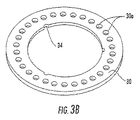
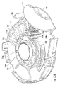
本発明の実施形態は、同心列に配置されたドーズ容器を有するドーズリングまたはドーズディスクの使用を容易にする、往復運動する内側および外側突刺機構を有するドライパウダー吸入器を提供することになる。いくつかの実施形態によれば、ドライパウダー吸入器は、異なる半径の第1および第2の同心列に配置された周方向において互いに離間した複数のドライパウダー容器を有するドーズ容器ディスクと、順次、第1の列のドライパウダードーズ容器を開封し、次いで、第2の列のドライパウダードーズ容器を開封するように構成された突刺機構と、を備えている。突刺機構は、半径方向において互いに隣接して離間した関係にある第1および第2の細長突刺部材を備えている。各突刺部材は、突刺位置と非突刺位置との間で往復運動することができるようになっており、遠位側突刺部および近位ヘッド部を備えている。第1の突刺部材は、第1の列におけるドーズ容器のシーリング材を突き刺すように構成されており、第2の突刺部材は、第2の列におけるドーズ容器のシーリング材を突き刺すように構成されている。 Embodiments of the present invention will provide a dry powder inhaler having reciprocating inner and outer piercing mechanisms that facilitate the use of a dose ring or dose disk having dose containers arranged in concentric rows. According to some embodiments, the dry powder inhaler comprises a dose container disk having a plurality of dry powder containers spaced apart from one another in a circumferential direction, arranged in first and second concentric rows of different radii, sequentially, A piercing mechanism configured to open the first row of dry powder dose containers and then to open the second row of dry powder dose containers. The piercing mechanism includes first and second elongated piercing members that are adjacent to each other and spaced apart from each other in the radial direction. Each piercing member can reciprocate between a piercing position and a non-piercing position, and includes a distal piercing portion and a proximal head portion. The first piercing member is configured to pierce the sealing material of the dose container in the first row, and the second piercing member is configured to pierce the sealing material of the dose container in the second row. Yes.
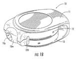
いくつかの実施形態によれば、ドライパウダー吸入器は、互いに向き合った上下主面と、第1の半径において周方向に互いに離間したドーズ容器の第1の列および第2の半径において周方向に互いに離間したドーズ容器の第2の列と、を有するドーズ容器ディスクを備えている。第1の列および第2の列は、ディスクの中心に対して同心になっている。ドーズ容器は、ドライパウダーを含んでいる。パウダーをドーズ容器内に含むために、第1の柔軟シーリング材が上面の開口を覆って配置されており、第2の柔軟シーリング材が下面の開口を覆って配置されている。 According to some embodiments, the dry powder inhaler comprises a top and bottom major surface facing each other, a first row of dose containers spaced circumferentially at a first radius and a circumferential direction at a second radius. A dose container disc having a second row of dose containers spaced apart from each other. The first and second rows are concentric with the center of the disc. The dose container contains dry powder. In order to include the powder in the dose container, a first flexible sealing material is disposed over the upper opening and a second flexible sealing material is disposed over the lower opening.
突刺機構は、ドーズ容器ディスクに操作可能に関連付けられており、ドーズ容器を密封している第1および第2のシーリング材を突き刺すように構成されている。突刺機構は、ドーズ容器ディスクにおけるドーズ容器の2つの列間で順次入れ替わる2つの往復運動する突刺具を備えている。各細長突刺部材は、各列におけるドーズ容器の第1および第2のシーリング材を突き刺すために、突き出され、かつ後退されるようになっている。各細長突刺部材は、遠位側突刺部および近位側ヘッド部を備えている。いくつかの実施形態では、遠位側突刺部は、シーリング材を突き刺すように構成された中実突刺具とすることができる。いくつかの実施形態では、遠位側突刺部は、回転せずに垂直方向に真っ直ぐ移動させることによって、シーリング材を突き刺すように構成されたコルク・スクリュー突刺具とすることができる。いくつかの実施形態では、遠位側突刺部は、例えば、シーリング材を突き刺すように構成された3つまたは4つのローブを有する溝付き突刺具を有することが可能である。 The piercing mechanism is operably associated with the dose container disk and is configured to pierce the first and second sealing materials sealing the dose container. The piercing mechanism includes two reciprocating piercing tools that are sequentially switched between two rows of dose containers in the dose container disk. Each elongated piercing member is protruded and retracted to pierce the first and second sealing materials of the dose containers in each row. Each elongated piercing member includes a distal piercing portion and a proximal head portion. In some embodiments, the distal piercing portion can be a solid piercing device configured to pierce the sealant. In some embodiments, the distal piercing portion may be a cork screw piercing device configured to pierce the sealant by moving straight in the vertical direction without rotating. In some embodiments, the distal piercing portion can have, for example, a grooved piercing tool having three or four lobes configured to pierce the sealant.
各細長突刺部材は、突刺位置と非突刺位置との間で往復運動することができるようになっている。突刺位置では、突刺部材の遠位側突刺部は、ドーズ容器の第1および第2のシーリング材を貫通している。後退位置では、遠位側突刺部は、ドーズ容器ディスクを自在に回転させるために、ドーズ容器の上方に後退している。付勢部材は、突刺部材の各々を後退位置に向かって付勢するように、構成されている。 Each elongated piercing member can reciprocate between a piercing position and a non-piercing position. In the piercing position, the distal piercing portion of the piercing member passes through the first and second sealing materials of the dose container. In the retracted position, the distal pierce is retracted above the dose container to freely rotate the dose container disk. The urging member is configured to urge each of the piercing members toward the retracted position.
回転可能な斜面ディスクは、互い違いの同心関係にある周方向において互いに離間した第1の斜面要素の組および第2の斜面要素の組を備えている。斜面ディスクは、一方向のみに回転するようになっており、ユーザによって前方に移動するアクチュエータ機構によって駆動され、吸入器のマウスピースカバーを閉じるユーザの動作によって、逆方向に戻るようになっている。ユーザがアクチュエータ機構を移動させた結果として、斜面ディスクが回転すると、第1の斜面要素の組は、第1の突刺部材を後退位置と突出位置との間で移動させるように構成されており、第2の斜面要素の組は、第2の突刺部材を後退位置と突出位置との間で移動させるように構成されている。斜面要素は、突刺しが第1の列および第2の列におけるドーズ容器間で入れ替わって行われるように、互い違いに配置されている。第1の斜面要素の組および第2の斜面要素の組における各斜面要素は、第1の傾斜部、平坦部、第2の傾斜部、および棚部を備えている。 The rotatable bevel disc includes a first set of bevel elements and a second set of bevel elements that are spaced apart from one another in the circumferential direction that are in alternating concentric relations. The inclined disk rotates in only one direction, and is driven by an actuator mechanism that moves forward by the user, and returns to the reverse direction by the user's action of closing the mouthpiece cover of the inhaler. . When the inclined disk rotates as a result of the user moving the actuator mechanism, the first set of inclined elements is configured to move the first piercing member between a retracted position and a protruding position; The second set of slope elements is configured to move the second piercing member between the retracted position and the protruding position. The bevel elements are staggered so that the piercing is performed between the dose containers in the first row and the second row. Each slope element in the first slope element set and the second slope element set includes a first slope portion, a flat portion, a second slope portion, and a shelf portion.
アクチュエータ機構は、ユーザによって、第1の位置と第2の位置との間で移動可能になっている。アクチュエータを第1の位置から第2の位置に移動させると、斜面ディスクが回転し、その結果、第1の斜面要素の組における斜面要素によって、第1の突刺部材が第1の列におけるドーズ容器の上および下のシーリング材を突き刺すことになる。次に(すなわち、吸入器が用いられた後)、アクチュエータを第1の位置から第2の位置に移動させると、斜面ディスクが回転し、その結果、第2の斜面要素の組における斜面要素によって、第2の突刺部材が第2の列におけるドーズ容器の上および下のシーリング材を突き刺すことになる。吸入器が用いられるたびに、この交互の突刺し手順が、繰り返されることになる。いくつかの実施形態では、第1の位置から第2の位置へのアクチュエータの移動によって、突刺部材は、ドーズ容器の上および下のシーリング材を突き刺し、次いで、部分的に後退するようになっている。 The actuator mechanism is movable between the first position and the second position by the user. When the actuator is moved from the first position to the second position, the bevel disk rotates so that the bevel container in the first row causes the first piercing member to be in the first row by the bevel elements in the first bevel element set. The top and bottom sealant will be pierced. Next (ie, after the inhaler is used), when the actuator is moved from the first position to the second position, the bevel disk rotates so that the bevel elements in the second set of bevel elements The second piercing member will pierce the sealing material above and below the dose containers in the second row. This alternate piercing procedure will be repeated each time the inhaler is used. In some embodiments, movement of the actuator from the first position to the second position causes the piercing member to pierce the sealing material above and below the dose container and then partially retract. Yes.
本発明の実施形態による吸入器は、従来の吸入器を上回る多数の利点を有している。例えば、2つの突刺部材の使用によって、単一の可動突刺具の位置および作動を厳密に制御する必要がなくなる。さらに、2つの突刺部材を用いることによって、各突刺部材の摩耗が著しく低減される。従って、単一の突刺部材のみを利用していた場合に必要とされる材料よりも安価な材料が、これらの突刺部材に用いられてもよいことになる。加えて、2つの突刺部材の構造によって、突刺部材を後退位置に付勢するのに用いられるバネの設計の融通性を高めることができる。例えば、バネは、突刺部材の下方に位置決めされる必要がない。従って、従来の吸入器装置よりも高さの必要条件が緩和された吸入装置を得ることができる。 Inhalers according to embodiments of the present invention have a number of advantages over conventional inhalers. For example, the use of two piercing members eliminates the need to strictly control the position and operation of a single movable piercing tool. Furthermore, by using two piercing members, the wear of each piercing member is significantly reduced. Therefore, a material that is less expensive than that required when only a single piercing member is used may be used for these piercing members. In addition, the structure of the two piercing members can increase the flexibility of the design of the spring used to bias the piercing member to the retracted position. For example, the spring need not be positioned below the piercing member. Thus, an inhaler device can be obtained in which the height requirements are relaxed compared to conventional inhaler devices.
別々の斜面ディスクとアクチュエータ機構とを用いることによって、本発明の実施形態による吸入装置の他の利点がもたらされることになる。ドーズ容器アセンブリの割出しが斜面ディスクによって駆動されるので、割出し機構をより大きい空間を利用できる吸入器の内部に移すことができ、これによって、吸入器の全体的な大きさを縮小することができる。斜面ディスクとアクチュエータ機構とが別々の構成部品になっているので、各々の材料選択を最適化することができる。例えば、斜面ディスクに対して良好な摩擦特性を有する材料を選択し、アクチュエータ機構に対して強度および装飾特徴を有する材料を選択することができる。 The use of separate bevel discs and actuator mechanisms will provide other advantages of the inhalation device according to embodiments of the present invention. Since the indexing of the dose container assembly is driven by the beveled disk, the indexing mechanism can be moved inside the inhaler where more space is available, thereby reducing the overall size of the inhaler Can do. Since the slope disk and actuator mechanism are separate components, each material selection can be optimized. For example, a material having good friction characteristics for a sloped disk can be selected and a material having strength and decorative features for an actuator mechanism can be selected.
一実施形態に関して記載されている本発明の態様は、特にこれに関して記載されていなくても、別の実施形態に含まれていてもよいことに留意されたい。すなわち、全ての実施形態および/または任意の実施形態の特徴は、どのような方法および/またはどのような連携によって組み合わされてもよい。出願人は、当初に出願された任意の請求項を変更する権利、またはそれに応じて任意の新規の請求項を出願する権利、例えば、当初に出願された任意の請求項を、当初そのように記載されていなくても、任意の他の請求項の任意の特徴に従属させ、および/または該特徴を含むように、補正することができる権利を保有するものである。本発明のこれらおよび他の目的および/または態様は、以下に述べる詳細な説明によって、さらに明らかになるだろう。 It should be noted that aspects of the invention described with respect to one embodiment may not be specifically described in this regard, but may be included in another embodiment. That is, the features of all embodiments and / or any embodiment may be combined by any method and / or any cooperation. The applicant shall be entitled to change any claim originally filed, or to file any new claim accordingly, for example, any claim originally filed as such. Although not mentioned, it retains the right to be subject to and / or amended to include any feature of any other claim. These and other objects and / or aspects of the present invention will become more apparent from the detailed description set forth below.
以下、本発明の実施形態が示されている添付の図面を参照して、本発明をさらに詳細に説明する。しかし、本発明は、多くの異なる形態で実施されてもよく、本明細書に記載されている実施形態に制限されると解釈されるべきではない。全体を通して、同様の番号は、同様の要素を指すものとする。図面において、明瞭にするために、いくつかの層、構成要素、または特徴部が誇張されていることがあり、破線は、他の規定がなければ、任意選択的な特徴部または操作過程を示している。加えて、一連の操作(または行程)は、特に他の規定がなければ、図面および/または特許請求の範囲に記載されている順番に制限されるものではない。1つの図面または実施形態に関して記載されている特徴は、特に記載または図示されていなくても、他の実施形態または図面に関連付けられていてもよいものとする。 The present invention will now be described in more detail with reference to the accompanying drawings, in which embodiments of the invention are shown. However, the present invention may be implemented in many different forms and should not be construed as limited to the embodiments set forth herein. Like numbers refer to like elements throughout. In the drawings, some layers, components, or features may be exaggerated for clarity and the dashed lines indicate optional features or steps of operation, unless otherwise specified. ing. In addition, the sequence of operations (or steps) is not limited to the order presented in the drawings and / or the claims, unless otherwise specified. Features described with respect to one drawing or embodiment may not be specifically described or illustrated, but may be associated with other embodiments or drawings.
層、領域、または基板のような特徴部が、他の特徴部または要素の「上(on)」に位置していると称されているとき、該特徴部は、他の特徴部または要素の上に直接位置していてもよいし、または介在する特徴および/または要素が存在していてもよいことを理解されたい。対照的に、ある要素が、他の特徴部または要素の「直接上(directly on)」に位置していると称されているとき、介在する要素は、存在していない。ある特徴部または要素が、他の特徴部または要素に「接続されている(connected)」、「取付けられている(attached)」、または「連結されている(coupled)」と称されているとき、該特徴部または要素は、他の要素に直接的に接続、取付け、または連結されていてもよいし、または介在する要素が存在していてもよいことも理解されたい。対照的に、ある特徴部または要素が、他の要素に「直接接続されている(directly connected)」、「直接取り付けられている(directly attached)」、または「直接連結されている(directly coupled)」と称されているとき、介在する要素は、存在していない。一実施形態に関して記載または図示されている場合でも、そのように記載または図示されている特徴部は、他の実施形態に適用されてもよい。 When a feature such as a layer, region, or substrate is said to be located “on” of another feature or element, the feature is It should be understood that there may be direct location on top or there may be intervening features and / or elements. In contrast, when an element is referred to as being "directly on" another feature or element, there are no intervening elements present. When a feature or element is referred to as “connected”, “attached”, or “coupled” to another feature or element It should also be understood that the feature or element may be directly connected, attached or coupled to other elements, or that there may be intervening elements present. In contrast, a feature or element is “directly connected”, “directly attached”, or “directly coupled” to another element. ", There are no intervening elements present. Even when described or illustrated with respect to one embodiment, features so described or illustrated may be applied to other embodiments.
本明細書に用いられている専門用語は、特定の実施形態を説明することのみを目的としており、本発明を制限することを意図するものではない。本明細書に用いられている単数形の「a」、「an」、および「the」は、文脈が明らかに別のことを示していない限り、複数形を含むことも意図されている。「〜を備える(comprises)」および/または「〜を備えている(comprising)」という用語は、本明細において用いられる場合、記述されている特徴、行程、操作、要素、および/または構成部品の存在を特定することになるが、1つまたは複数の他の特徴、行程、操作、要素、構成部品、および/またはそれらの群の存在または追加を排除するものではないことをさらに理解されたい。本発明に用いられている「および/または」という用語は、1つまたは複数の互いに関連して列挙されている項目のいずれかの組合せおよび全ての組合せを含んでいる。 The terminology used herein is for the purpose of describing particular embodiments only and is not intended to be limiting of the invention. As used herein, the singular forms “a”, “an”, and “the” are intended to include the plural forms as well, unless the context clearly indicates otherwise. The terms “comprises” and / or “comprising”, as used herein, refer to features, processes, operations, elements, and / or components that are described. It should be further understood that the presence will be identified but does not exclude the presence or addition of one or more other features, processes, operations, elements, components, and / or groups thereof. The term “and / or” as used in the present invention includes any and all combinations of one or more of the listed items in relation to each other.
「〜の下に(under)、「〜の下方に(below)」、「〜の下側の(lower)」、「〜の上方に(over)」、「〜の上側の(upper)」などの空間に関連する用語は、図面に示されている1つの要素または特徴部と1つまたは複数の他の要素または特徴部との関係を説明するための記述を容易にするために、本明細書において用いられることがある。空間に関連するこれらの用語は、図面に描かれている方位に加えて、使用時または操作時における装置の異なる方位を含むことも意図されていることを理解されたい。例えば、もし図面における装置が倒置された場合、他の要素または特徴部の「下(under)」または「真下(beneath)」に位置していると記述されている要素は、他の要素または特徴部の「上(over)」に配向されることになる。従って、「〜下に(under)」という例示的な用語は、上向きの方位と下向きの方位の両方を含んでいることになる。装置は、これ以外に配向されることもあるが、(すなわち、90°または他の方位に回転されることもあるが)、この場合、本明細書に用いられている空間に関連する記述用語も、それに応じて、解釈されるとよい。同様に、本明細書では、「上向きに(upwardly)」、「下向きに(downwardly)、「垂直の(vertical)、「水平の(horizontal)」などの用語は、特に他の規定がなければ、説明の目的でのみ用いられている。 “Under”, “below”, “lower”, “over”, “upper”, etc. The terminology relating to the spaces in this specification is intended to facilitate the description to describe the relationship between one element or feature shown in the drawings and one or more other elements or features. May be used in writing. It should be understood that these terms related to space are intended to include different orientations of the device in use or operation, in addition to the orientation depicted in the drawings. For example, if an apparatus in the drawing is inverted, an element described as being “under” or “beneath” of another element or feature may be It will be oriented “over” the part. Thus, the exemplary term “under” includes both upward and downward orientations. The device may be otherwise oriented (ie it may be rotated 90 ° or other orientations), but in this case, descriptive terms relating to the space used herein. Should be interpreted accordingly. Similarly, in this specification, terms such as “upwardly”, “downwardly”, “vertical”, “horizontal” and the like, unless otherwise specified, Used for illustrative purposes only.
本明細書では、種々の領域、層、および/または区域を記載するために、「第1の」および「第2の」という用語が用いられているが、これらの領域、層および/または区域は、これらの用語に制限されるべきではないことを理解されたい。これらの用語は、1つの領域、層、または区域を他の領域、層、または区域から区別するためにのみ用いられているにすぎない。従って、本発明の示唆から逸脱することなく、以下に述べる第1の領域、層、または区域は、第2の領域、層、または区域と呼ばれてもよく、同様に、以下に述べる第2の領域、層、または区域は、第1の領域、層、または区域と呼ばれてもよい。全体を通して、同様の部番は、同様の要素を指すものとする。 In this specification, the terms "first" and "second" are used to describe various regions, layers, and / or areas, but these regions, layers, and / or areas It should be understood that should not be limited to these terms. These terms are only used to distinguish one region, layer, or area from another region, layer, or area. Accordingly, without departing from the teachings of the present invention, the first region, layer, or area described below may be referred to as the second region, layer, or area, as well as the second region described below. This region, layer or area may be referred to as the first region, layer or area. Throughout, like part numbers shall refer to like elements.
他の定義がなければ、本明細書に用いられている(技術用語および科学用語を含む)全ての用語は、本発明が属する技術分野における当業者によって一般的に理解されるのと同じ意味を有している。一般的に用いられる辞書に定義されているような用語は、本明細書および関連技術の文脈における意味と一致している意味を有するものと解釈されるべきであり、本明細書に明示的に規定されていない限り、理想化された意味または過度に形式的な意味に解釈されるべきではないことをさらに理解されたい。周知の機能または構造は、簡潔にするためおよび/または明瞭にするために、詳細に記載されていないことがある。 Unless defined otherwise, all terms used herein (including technical and scientific terms) have the same meaning as commonly understood by one of ordinary skill in the art to which this invention belongs. Have. Terms as defined in commonly used dictionaries should be construed as having a meaning consistent with the meaning in the present specification and the context of the related art, and are expressly stated herein. It should be further understood that unless otherwise specified, it should not be interpreted in an idealized or overly formal sense. Well-known functions or constructions may not be described in detail for brevity and / or clarity.
以下に述べる本発明の説明において、ある構造と他の構造との間の位置関係に言及するのに、いくつかの用語が用いられている。本明細書において用いられる「前方(front)」または「前方の(forward)」およびその派生語は、ドライパウダーが、ドライパウダー吸入器から患者に投与されるために移動する一般方向または主方向を指している。この用語は、「下流の(downstream)」という用語と同意語であることが意図されている。「下流」という用語は、移動しているまたは反応しているある材料が、そのプロセスに沿って他の材料よりも遠くにあることを示すために、製造環境または物流環境において用いられることが多い。逆に、「後方の(rearward)」または「上流の(upstream)およびその派生語は、前方または下流方向と反対の方向を指している。「解凝集(deagglomeration)」という用語およびその派生語は、吸息中にドライパウダーが凝集または粘着した状態になったままになっているかまたは凝集または粘着することを阻止するように、吸入器の気道経路内のドライパウダーを処理することを指している。 In the following description of the invention, a number of terms are used to refer to the positional relationship between one structure and another. As used herein, “front” or “forward” and its derivatives refer to the general or main direction in which dry powder travels to be administered from a dry powder inhaler to a patient. pointing. This term is intended to be synonymous with the term “downstream”. The term “downstream” is often used in a manufacturing or logistics environment to indicate that one material that is moving or reacting is farther than other materials along the process. . Conversely, “rearward” or “upstream” and its derivatives refer to the direction opposite to the forward or downstream direction. The term “deagglomeration” and its derivatives are Refers to treating dry powder in the airway pathway of the inhaler so that the dry powder remains agglomerated or sticky during inhalation or prevents it from clumping or sticking .
本発明の吸入器および方法は、一種または複数種の粒状のドライパウダー物質の1回分または複数回分の局部的または急速ドーズ量を保持するのに、特に適している。なお、該ドライパウダー物質は、対象、例えば、制限されるものではないが、動物、典型的には、ヒト患者への(吸入器を用いる)生体内吸入分散用に配合されるものである。この吸入器は、経鼻および/または経口(口)呼吸による吸入送達に用いられるようになっているが、典型的には、経口吸入器である。 The inhaler and method of the present invention is particularly suitable for maintaining one or more local or rapid doses of one or more granular dry powder materials. It should be noted that the dry powder material is formulated for in vivo inhalation dispersion (using an inhaler) to a subject, such as, but not limited to, an animal, typically a human patient. The inhaler is adapted for inhalation delivery by nasal and / or oral (oral) breathing, but is typically an oral inhaler.
「シーリング材(sealant)、「シーリング層(sealant layer)」および/または「シーリング材料(sealant material)」という用語は、少なくとも一種の材料の少なくとも1つの層を有している形態を含んでおり、上面および/または下面の全体を覆う連続層として設けられていてもよいし、または、例えば、少なくとも目標とする1つまたは複数のドーズ容器開口の上に位置するように、装置の一部を覆う帯片または断片として設けられていてもよい。「シーリング材」および「シーリング層」という用語は、単一層材料および多層材料を含んでおり、典型的には、少なくとも1つの箔層を含んでいる。シーリング材またはシーリング層は、エラストマー材料および箔材料を含む積層構造の薄い多層シーリング材料とすることができる。シーリング層は、各ドーズ容器内のドライパウダーと接触するときに薬剤安定性をもたらすように、選択されてもよい。 The terms “sealant,” “sealant layer” and / or “sealant material” include forms having at least one layer of at least one material; It may be provided as a continuous layer covering the entire upper and / or lower surface, or cover a part of the device, for example at least over the target dose container opening or openings It may be provided as a strip or piece. The terms “sealant” and “sealing layer” include single layer materials and multilayer materials, and typically include at least one foil layer. The sealing material or sealing layer can be a thin multilayer sealing material with a laminated structure comprising an elastomeric material and a foil material. The sealing layer may be selected to provide drug stability when in contact with the dry powder in each dose container.
「往復運動する」という用語は、突刺部材が、それぞれのドーズ容器を開封するために、上下に移動することを意味している。 The term “reciprocating” means that the piercing member moves up and down to open each dose container.
密封されたドーズ容器は、十分な保存可能期間をもたらすために、酸素および湿気の侵入を阻止するように、構成されているとよい。 The sealed dose container may be configured to prevent oxygen and moisture ingress to provide sufficient shelf life.
「主面(primary surface)」という用語は、他の表面よりも大きな面積を有する表面を指しており、実質的に平面とすることができるが、非平面に構成されていてもよい。例えば、主面は、例えば、ブリスター構成が用いられる場合、突起または凹部を備えることになる。具体的には、ディスクは、上下主面と、2つの主面間に延在してそれらを接続する副次的な表面(例えば、厚みを有する壁)と、を有することができる。 The term “primary surface” refers to a surface having a larger area than other surfaces and may be substantially planar, but may be configured to be non-planar. For example, the main surface will be provided with protrusions or recesses, for example when a blister configuration is used. Specifically, the disc may have an upper and lower main surface and a secondary surface (for example, a wall having a thickness) that extends between the two main surfaces and connects them.
ドライパウダー物質として、所望の配合物あるいは混合物を生成するための一種または複数種の活性製薬成分および生体適合性添加剤が挙げられる。本明細書において用いられている「ドライパウダー」という用語は、「ドライパウダー配合物」という用語と同意語であり、1つまたは複数の(平均)粒径範囲内にある一種または複数種の構成物質または成分を含むことができることを意味している。「低密度(low density)」ドライパウダーという用語は、約0.8g/cm3以下の密度を有するドライパウダーを意味している。特定の実施形態では、低密度粉末は、約0.5g/cm3以下の密度を有している。このドライパウダーは、粘着性傾向あるいは凝集性傾向のあるドライパウダーであってもよい。 Dry powder materials include one or more active pharmaceutical ingredients and biocompatible additives to produce the desired formulation or mixture. As used herein, the term “dry powder” is synonymous with the term “dry powder formulation” and includes one or more configurations within one or more (average) particle size ranges. It means that a substance or component can be included. The term “low density” dry powder means a dry powder having a density of about 0.8 g / cm 3 or less. In certain embodiments, the low density powder has a density of about 0.5 g / cm 3 or less. This dry powder may be a dry powder that tends to be sticky or cohesive.
「充填(filling)」という用語は、ボーラス投与または副ボーラス投与用に計量されたドライパウダーを供給することを意味している。従って、それぞれのドーズ容器は、必ずしも容積的に十分である必要がない。 The term “filling” means supplying a dry powder that is metered for bolus or secondary bolus administration. Thus, each dose container need not necessarily be sufficient in volume.
いずれにしても、個別に分散可能な量のドライパウダー配合物は、活性あるいは不活性に関わらず、単一成分または複数成分を含むことができる。不活性成分として、流動性を促進するためにあるいは所望の対象へのエアゾール化送出を促進するために加えられる添加剤が挙げられる。ドライパウダー薬剤配合物は、一様でない活性粒径を有することができる。本装置は、約0.5μm〜50μm、典型的には、約0.5μm〜20.0μm、さらに典型的には、約0.5μm〜8.0μmの範囲内にある微粒子を有するドライパウダー配合物に特に適している。ドライパウダー薬剤配合物は、典型的には活性成分の粒径よりも大きい粒径を有する流れ促進用成分を含むこともできる。いくつかの実施形態では、流れ促進用成分は、約50μm〜100μmの範囲内の粒径を有する賦形剤を含んでいてもよい。賦形剤の例として、ラクトースおよびトレハロースが挙げられる。他の種類の賦形剤、例えば、制限されるものではないが、米国食品医薬品局(FDA)によって、凍結防止剤(例えば、マンニトール)として、溶解度促進剤(例えば、シクロデキストリン)として、または「一般に安全であると認められる(GRAS)」他の賦形剤として認可された糖類が用いられてもよい。 In any event, individually dispersible amounts of the dry powder formulation can include a single component or multiple components, whether active or inactive. Inert ingredients include additives that are added to promote fluidity or to facilitate aerosolization delivery to the desired object. Dry powder drug formulations can have non-uniform active particle sizes. The apparatus comprises a dry powder formulation having particulates in the range of about 0.5 μm to 50 μm, typically about 0.5 μm to 20.0 μm, more typically about 0.5 μm to 8.0 μm. Especially suitable for things. Dry powder drug formulations may also include a flow promoting component that typically has a particle size larger than the particle size of the active ingredient. In some embodiments, the flow promoting component may include an excipient having a particle size in the range of about 50 μm to 100 μm. Examples of excipients include lactose and trehalose. Other types of excipients, such as, but not limited to, the US Food and Drug Administration (FDA), as a cryoprotectant (eg, mannitol), as a solubility enhancer (eg, cyclodextrin), or “ Approved sugars may be used as other excipients that are “generally recognized as safe (GRAS)”.
本明細書に記載されている「活性剤(active agent)」あるいは「活性成分(active ingredient)」は、有益な薬理効果をもたらす成分、物質、薬剤、化合物、および物質あるいは混合物の組成物を含んでいる。この例として、食品、栄養補助食品、栄養物、薬剤、ワクチン、ビタミン、および他の有益物質が挙げられる。本明細書において用いられるこれらの用語は、患者の体内で局部的および/または全身的効果をもたらす何らかの生理学的活性物質あるいは薬理学的活性物質をさらに含んでいる。 As used herein, “active agent” or “active ingredient” includes components, substances, agents, compounds, and compositions of substances or mixtures that provide beneficial pharmacological effects. It is out. Examples of this include foods, dietary supplements, nutrients, drugs, vaccines, vitamins, and other beneficial substances. These terms as used herein further include any physiologically or pharmacologically active substance that produces a local and / or systemic effect in the patient's body.
送達される活性成分あるいは活性剤は、抗生物質、抗ウイルス物質、抗癲癇剤、鎮痛剤、抗炎症剤、および気管支拡張剤を含むことができ、無機および/または有機化合物であってもよい。無機および/または有機化合物は、制限されるものではないが、末梢神経、アドレナリン受容体、コリン受容体、骨格筋、心臓血管系、平滑筋、血管系、シノプティック部位、神経効果器接合部、内分泌・ホルモン系、免疫系、生殖器系、骨格系、自家薬物系、消化排出系、ヒスタミン系、および中枢神経系に作用する薬剤を含んでいる。適切な活性剤は、例えば、制限されるものではないが、多糖類、ステロイド、睡眠薬および鎮静剤、精神賦活剤、トランキライザー、抗痙攣薬、筋肉弛緩剤、抗パーキンソン剤、鎮痛剤、抗炎症剤、筋収縮剤、抗菌薬、抗マラリア薬、避妊薬を含むホルモン剤、交感神経興奮剤、(生理学的効果を誘出することができる)ポリペプチドおよび/またはタンパク質、利尿剤、高脂血症治療薬、抗アンドロゲン剤、駆虫薬、組織新生薬、抗腫瘍薬、血糖低下薬、栄養剤および栄養補助食品、成長補助食品、脂質、抗腸炎薬、電解質、ワクチンおよび診断用薬から選択されるとよい。 Active ingredients or active agents delivered can include antibiotics, antiviral agents, antiepileptic agents, analgesics, anti-inflammatory agents, and bronchodilators, and can be inorganic and / or organic compounds. Inorganic and / or organic compounds include, but are not limited to, peripheral nerves, adrenergic receptors, cholinergic receptors, skeletal muscle, cardiovascular system, smooth muscle, vascular system, synoptic sites, neuroeffector junctions, Contains drugs that affect the endocrine / hormonal system, immune system, genital system, skeletal system, autologous drug system, digestive excretion system, histamine system, and central nervous system. Suitable active agents include, but are not limited to, polysaccharides, steroids, hypnotics and sedatives, psychostimulants, tranquilizers, anticonvulsants, muscle relaxants, antiparkinsonians, analgesics, anti-inflammatory agents , Muscle contractors, antibacterials, antimalarials, hormonal agents including contraceptives, sympathomimetics, polypeptides and / or proteins (which can elicit physiological effects), diuretics, hyperlipidemia Selected from therapeutics, antiandrogens, anthelmintics, histogenesis, antineoplastics, hypoglycemics, nutrients and dietary supplements, growth supplements, lipids, antienteritis drugs, electrolytes, vaccines and diagnostics Good.
活性剤は、天然の分子であってもよいし、遺伝子組換えによって生じたものであってもよいし、あるいは一種または複数種のアミノ酸が追加または除去された天然活性剤あるいは遺伝子組換え活性剤からなる類似物であってもよい。さらに、活性剤は、ワクチンとして用いられるのに適した弱毒ウイルスあるいは不活化ウイルスを含んでいてもよい。活性剤がインスリンであるとき、「インスリン」という用語は、天然抽出ヒトインスリン、遺伝子組換えヒトインスリン、ウシおよび/またはブタおよび/または他の供給源から抽出されたインスリン、遺伝子組換えブタ、ウシあるいは他の適切なドナーから抽出されたインスリン、およびこれらのいずれかの混合物を含んでいる。インスリンは、純粋なもの(すなわち、その実質的に純化された形態にあるもの)であるとよいが、商業的に製剤化された賦形剤を含んでいてもよい。また、「インスリン」という用語には、天然インスリンまたは遺伝子組換えインスリンに対して一種または複数種のアミノ酸が除去または追加されているインスリン類似物も含まれている。 The active agent may be a natural molecule, may be generated by gene recombination, or may be a natural active agent or gene recombination active agent in which one or more amino acids are added or removed. An analog consisting of Furthermore, the active agent may comprise an attenuated virus or an inactivated virus suitable for use as a vaccine. When the active agent is insulin, the term “insulin” refers to naturally extracted human insulin, recombinant human insulin, insulin extracted from bovine and / or pigs and / or other sources, genetically modified pigs, bovine Alternatively, it contains insulin extracted from other suitable donors, and mixtures of any of these. Insulin may be pure (ie, in its substantially purified form), but may include commercially formulated excipients. The term “insulin” also includes insulin analogues in which one or more amino acids have been removed or added to natural or genetically modified insulin.
2種以上の活性成分あるいは活性剤が、エアゾール化活性剤配合物に含まれていてもよく、「剤(agent)」または「成分(ingredient)」という用語の使用は、2種以上のこのような物質の使用を決して排除するものではないことを理解されたい。実際、本発明のいくつかの実施形態では、現場で混合されることになる組合せ薬剤を投与することが意図されている。 More than one active ingredient or active agent may be included in an aerosolized active agent formulation, and the use of the term “agent” or “ingientient” is more than one such It should be understood that this does not preclude the use of other substances. Indeed, in some embodiments of the invention, it is contemplated to administer a combination drug that will be mixed in the field.
本発明の実施形態によって治療可能な病気、健康状態、または疾患の例として、制限されるものではないが、糖尿病および他のインスリン抵抗性疾患に加えて、喘息、COPD(慢性閉塞性肺疾患)、ウイルス感染症または細菌感染症、インフルエンザ、アレルギー反応、嚢胞性線維症、および他の呼吸器疾患が挙げられる。ドライパウダー吸入は、全身性薬、例えば、ロイプロリドのようなペプチドおよびインスリンのようなタンパク質のみならず、抗菌薬、タンパク質分解酵素抑制剤、および核酸/オリギオヌクレオチドのような局所作用薬を送達するために用いられてもよい。例えば、抗結核性化合物のような抗菌薬、糖尿病療法あるいは他のインスリン抵抗性関連疾患のためのインスリンのようなタンパク質、前立腺癌および/または子宮内膜症の治療のための酢酸ロイプロリドのようなペプチド、および嚢胞性線維症遺伝子療法のための核酸またはオグリゴヌクレオチドが、吸入器によって送達されるとよい。例えば、ウォルフら:「エアロゾル化薬剤の生成」、J.Aerosol.Med.pp.89−106(1994)を参照されたい。また、「ASPB28−ヒトインスリンを投与する方法」と題する米国特許出願公開第2001/0053761号明細書、および「単量体インスリン類似物を投与する方法」と題する米国特許出願公開第2001/0007853号明細書を参照されたい。なお、これらの特許の内容は、参照することによって、あたかも完全に記載されているかのように、ここに含まれるものとする。 Examples of diseases, health conditions, or diseases that can be treated by embodiments of the present invention include, but are not limited to, asthma, COPD (chronic obstructive pulmonary disease) in addition to diabetes and other insulin resistant diseases. , Viral or bacterial infections, influenza, allergic reactions, cystic fibrosis, and other respiratory diseases. Dry powder inhalation delivers systemic drugs such as peptides such as leuprolide and proteins such as insulin, as well as topical agents such as antibacterial drugs, proteolytic enzyme inhibitors, and nucleic acids / origionucleotides May be used for For example, antibacterial agents such as antituberculosis compounds, proteins such as insulin for diabetes therapy or other insulin resistance related diseases, leuprolide acetate for the treatment of prostate cancer and / or endometriosis Peptides and nucleic acids or oglygonucleotides for cystic fibrosis gene therapy may be delivered by inhaler. For example, Wolf et al .: “Production of aerosolized drugs”, J. Am. Aerosol. Med. pp. 89-106 (1994). Also, U.S. Patent Application Publication No. 2001/0053761 entitled "ASPB28-Method of Administering Human Insulin" and U.S. Patent Application Publication No. 2001/0007853 entitled "Method of Administering Monomeric Insulin Analogue". See the description. The contents of these patents are hereby incorporated by reference as if they were fully described.
吸入器内に分散される単位となるドライパウダー混合物の典型的なドーズ量は、患者の背格好、全身の標的部位、および特定の一種または複数の薬剤に応じて、変更することができる。ドーズ容器システムによって保持される薬剤のドーズ量および種類は、ドーズ容器ごとに異なっていてもよいし、または同じであってもよい。いくつかの実施形態では、ドライパウダーのドーズ量は、約100mg以下、典型的には、50mg未満、さらに典型的には、約0.1mgから約30mgの間とすることができる。 The typical dose of the dry powder mixture as a unit dispersed in the inhaler can vary depending on the patient's back appearance, the systemic target site, and the particular drug or drugs. The dose amount and type of drug held by the dose container system may be different for each dose container, or may be the same. In some embodiments, the dry powder dose can be about 100 mg or less, typically less than 50 mg, and more typically between about 0.1 mg to about 30 mg.
いくつかの実施形態では、例えば、肺疾患(すなわち、喘息またはCOPD)の場合、全重量で約5mmgのドライパウダーが供給されるとよい(ドーズ量は、この重量を供給するために、調整されるとよい)。従来の例示的なドライパウダーのドーズ量は、平均的成人の場合、約50mg未満、典型的には、約10mg−30mgの間であり、平均的青少年患者の場合、典型的には、約5mm−10mgの間である。典型的なドーズ濃度は、約1%−5%の間であるとよい。例示的なドライパウダー薬剤の例として、制限されるものではないが、アルブテロール、フルチカゾン、ベクロメタゾン、クロモリン、テルブタリン、フェノテロール、(持続性β刺激薬を含む)β刺激薬、サルメテロール、フォルモテロール、皮質ステロイド、およびグルココルチコイドが挙げられる。 In some embodiments, for example, in the case of pulmonary disease (ie, asthma or COPD), about 5 mmg of dry powder may be provided in total weight (the dose is adjusted to provide this weight). Good). Conventional exemplary dry powder doses are less than about 50 mg for an average adult, typically between about 10 mg-30 mg, and typically about 5 mm for an average adolescent patient. Between -10 mg. A typical dose concentration may be between about 1% -5%. Examples of exemplary dry powder drugs include, but are not limited to, albuterol, fluticasone, beclomethasone, cromolyn, terbutaline, fenoterol, beta stimulants (including persistent beta stimulants), salmeterol, formoterol, cortical steroids , And glucocorticoids.
いくつかの実施形態では、投与されるボーラス量またはドーズ量は、従来の混合物よりも高濃度になるように(高濃度の活性成分が含まれるように)、配合することができる。さらに、ドライパウダーの配合物は、従来の10〜25mgドーズと比較して、より低投与量のドーズとして構成することができる。例えば、投与可能なドライパウダーの各ドーズ量は、従来のドーズの約60〜70%未満とすることができる。本発明のDPI構成のいくつかの実施形態によって提供される分散システムを用いることによって、成人のドーズ量は、約15mg未満、例えば、約10μg〜10mgの間、さらに典型的には、約50μg〜10mgに減少している。一種または複数種の活性成分の濃度は、約5〜10%であるとよい。他の実施形態では、活性成分の濃度は、約10〜20%の範囲内、20〜25%の範囲内、またはそれ以上の範囲内とすることができる。特定の実施形態では、経鼻吸入の場合、目標ドーズ量は、約12μg〜100μgとすることができる。 In some embodiments, the amount of bolus or dose administered can be formulated to be higher (contains a higher concentration of active ingredient) than a conventional mixture. Furthermore, the dry powder formulation can be configured as a lower dose dose compared to the conventional 10-25 mg dose. For example, each dose of dry powder that can be administered can be less than about 60-70% of a conventional dose. By using a distributed system provided by some embodiments of the DPI configuration of the present invention, the adult dose is less than about 15 mg, such as between about 10 μg and 10 mg, more typically between about 50 μg and Reduced to 10 mg. The concentration of one or more active ingredients may be about 5-10%. In other embodiments, the concentration of the active ingredient can be in the range of about 10-20%, in the range of 20-25%, or more. In certain embodiments, for nasal inhalation, the target dose can be about 12 μg to 100 μg.
いくつかの特定の実施形態では、吸入中、特定の薬剤区画またはブリスター内のドライパウダーは、(賦形剤のような)添加物を実質的に含まない高濃度の一種または複数種の活性薬剤成分として配合されていてもよい。本明細書において用いられる「実質的に添加物を含まない(substantially without additives)」という用語は、ドライパウダーが、最小量の他の非生体薬学的活性成分しか含んでいない実質的に純粋の活性配合物であることを意味している。「最小量」という用語は、非活性成分が、含まれていないか、または一種または複数種の活性成分に対して極めて少量、具体的には、投与されるドライパウダー配合物の約10%未満、好ましくは、約5%未満の量しか含まれていないこと、およびいくつかの実施形態では、非活性成分が一定基準値以下の微量しか含まれていないことを意味している。 In some specific embodiments, during inhalation, the dry powder in a particular drug compartment or blister is a high concentration of one or more active agents that are substantially free of additives (such as excipients). It may be blended as a component. As used herein, the term “substantially without additives” refers to substantially pure activity in which the dry powder contains minimal amounts of other non-biopharmaceutical active ingredients. It means that it is a blend. The term “minimum amount” is free of inactive ingredients or is very small relative to one or more active ingredients, specifically less than about 10% of the dry powder formulation being administered. , Preferably, means less than about 5%, and in some embodiments means that the inactive ingredients contain only trace amounts below a certain reference value.
いくつかの実施形態では、各薬剤区画またはドーズ容器内に保持されているドライパウダーの単位ドーズ量は、喘息のような肺疾患を治療する場合には、10mg未満、典型的には、約5mg未満の薬剤および乳糖または他の添加物の混合物(例えば、5mgのLAC)である。純インスリン換算で約4mg未満、典型的には、約3.6mgのインスリンが施されてもよい。ドライパウダーは、「圧縮して(compressed)」または部分的圧縮してドーズ容器/薬剤区画内に挿入されていてもよいし、または自在に流動する粒子として含有されていてもよい。 In some embodiments, the unit dose of dry powder held in each drug compartment or dose container is less than 10 mg, typically about 5 mg, when treating lung diseases such as asthma. A mixture of less drug and lactose or other additives (eg, 5 mg LAC). Less than about 4 mg, typically about 3.6 mg of insulin in terms of pure insulin may be administered. The dry powder may be “compressed” or partially compressed and inserted into the dose container / drug compartment, or may be contained as freely flowing particles.
本発明のいくつかの実施形態は、組合せ送達を行うために、互いに異なる多数の薬剤を送達することができる吸入器を対象としている。従って、例えば、いくつかの実施形態では、ドーズ容器のいくつかまたは全てが、2種類の異なる薬剤を含んでいてもよいし、または互いに異なる薬剤を含む互いに異なるドーズ容器が、実質的に同時に投与するように構成されていてもよい。 Some embodiments of the present invention are directed to an inhaler that can deliver a number of different drugs to each other for performing combination delivery. Thus, for example, in some embodiments, some or all of the dose containers may contain two different drugs, or different dose containers containing different drugs may be administered substantially simultaneously. It may be configured to.
いくつかの実施形態では、吸入装置用のドーズ容器ディスクは、第1の半径において周方向に互いに離間したドーズ容器の第1の列および第2の半径において周方向に互いに離間したドーズ容器の第2の列を備えており、第1の列および第2の列が実質的に同心になっているとよい。いくつかの実施形態では、同一の薬剤が、ドーズ容器の全てに含まれているとよい。他の実施形態では、第1の薬剤が、第1の列のドーズ容器内に含まれ、第1の薬剤と異なる第2の薬剤が、第2の列のドーズ容器内に含まれるようになっていてもよい。 In some embodiments, a dose container disk for an inhaler device includes a first row of dose containers spaced circumferentially from each other at a first radius and a first of dose containers spaced circumferentially from each other at a second radius. Preferably, two columns are provided, and the first column and the second column are substantially concentric. In some embodiments, the same drug may be included in all of the dose containers. In other embodiments, the first drug is contained in the first row of dose containers, and a second drug different from the first drug is contained in the second row of dose containers. It may be.
吸入器は、どのような適切な数のドーズ、典型的には、約30〜120個のドーズ、さらに典型的には、約30〜60個のドーズを含有するように構成されていてもよい。吸入器は、一種類の薬剤または組合せ薬剤を送達することができる。いくつかの実施形態では、吸入器は、(単位量が同じであってもよいし、または異なっていてもよい)互いに異なる2種類の薬剤からなる約30〜60個のドーズ、従って、合計では約60〜120個の単位ドーズを含んでいてもよい。吸入器は、30日から60日(またはそれ以上)の期間にわたって、薬剤を供給することができる。いくつかの実施形態では、吸入器は、(単位量が同じであってもよいし、または異なっていてもよい)同一の薬剤または同一の組合せ薬剤からなる約60個のドーズを含むように構成されていてもよい。これによって、(一日に2回投与する場合)、該薬剤を30日にわたって供給することができ、毎日一回治療する場合、該薬剤を60日にわたって供給することができる。 The inhaler may be configured to contain any suitable number of doses, typically about 30-120 doses, and more typically about 30-60 doses. . The inhaler can deliver one type of drug or a combination drug. In some embodiments, the inhaler has about 30-60 doses of two different types of drugs (which may be the same or different in unit dose), and therefore in total About 60 to 120 unit doses may be included. The inhaler can deliver medication over a period of 30 to 60 days (or more). In some embodiments, the inhaler is configured to include about 60 doses of the same drug or the same combination drug (which may be the same or different in unit dosage). May be. This allows the drug to be delivered over 30 days (when administered twice a day) and the drug can be delivered over 60 days if treated once daily.
いくつかの実施形態は、呼吸器患者、糖尿病患者、嚢胞性線維症患者、または苦痛を治療する患者に対して薬剤を投与するのに、特に適している。この吸入器は、麻酔薬、ホルモン、および/または不妊治療薬を投与するのに用いられてもよい。 Some embodiments are particularly suitable for administering the drug to respiratory patients, diabetic patients, cystic fibrosis patients, or patients treating distress. The inhaler may be used to administer anesthetics, hormones, and / or fertility drugs.
このドーズ容器アセンブリおよび吸入器は、呼吸器疾患の治療用の薬剤を投与するのに特に適している。適切な薬剤は、例えば、鎮痛剤、例えば、コデイン、ジヒドロモルヒネ、エルゴタミン、フェンタニル、またはモルヒネ;狭心症製剤、例えば、ジルチアゼム;抗アレルギー物質、例えば、クロモグリケイト、ケトチフェン、またはネドクロミル;抗感染薬、例えば、セファロスポリン、ペニシリン、ストレプトマイシン、スルホンアミド、テトラサイクリン、およびペンタミジン;抗ヒスタミン剤、例えば、メタピリレン;抗炎症薬、例えば、ジプロピオン酸ベクロメタゾン、プロピオン酸フルチカゾン、フルニソリド、ブデソニド、ロフレポニド、フロ酸モメタゾン、またはトリアムシノロンアセトニド;鎮咳剤、例えば、ノスカピン;気管支拡張剤、例えば、アルブテロール、サルメテロール、エフェドリン、アドレナリン、フェノテロール、フォルモテロール、イソプレナリン、メタプロテレノール、フェニレフリン、フェニルプロパノールアミン、ピルブテロール、レプロテロール、リミテロール、テルブタリン、イソエタリン、ツロブテロール、または(−)−4−アミノ−3,5−ジクロロ−α−[[6−[2−(2−ピリジニル)エトキシ」ヘキシル]メチル]ベンゼンメタノール;利尿剤、例えば、アミロリド;抗コリン作用薬、例えば、イプラトロピウム、チオトロピウム、アトロピン、またはオキシトロピウム;ホルモン、例えば、コルチゾン、ヒドロコルチゾン、またはプレドニゾロン;キサンチン、例えば、アミノフィリン、コリンテオフィリナート、リシンテオフィリナート、またはテオフィリン;治療用タンパク質およびペプチド、例えば、インスリンまたはグルカゴン、から選択されるとよい。もし適切であれば、これらの薬剤は、薬剤の活性および/または安定性を最適化させるために、塩の形態で(例えば、アルカリ金属またはアミン塩または酸添加塩として)用いられてもよいし、エステル(例えば、低アルキルエステル)として用いられてもよいし、または溶媒和物(例えば、水和物)として用いられてもよいことが、当業者には明らかであろう。 This dose container assembly and inhaler is particularly suitable for administering medicaments for the treatment of respiratory diseases. Suitable agents include, for example, analgesics such as codeine, dihydromorphine, ergotamine, fentanyl, or morphine; angina preparations such as diltiazem; antiallergic agents such as cromoglycate, ketotifen, or nedocromil; Drugs such as cephalosporin, penicillin, streptomycin, sulfonamides, tetracyclines, and pentamidine; antihistamines such as metapyrene; anti-inflammatory drugs such as beclomethasone dipropionate, fluticasone propionate, flunisolide, budesonide, rofleponide, mometasone furoate Or triamcinolone acetonide; antitussives such as noscapine; bronchodilators such as albuterol, salmeterol, ephedrine, adrenaline, fenote , Formoterol, isoprenaline, metaproterenol, phenylephrine, phenylpropanolamine, pyrbuterol, reproterol, limiterol, terbutaline, isoetarine, tulobuterol, or (−)-4-amino-3,5-dichloro-α-[[6 -[2- (2-pyridinyl) ethoxy "hexyl] methyl] benzenemethanol; diuretics such as amiloride; anticholinergics such as ipratropium, tiotropium, atropine or oxitropium; hormones such as cortisone, hydrocortisone Xanthine, such as aminophylline, choline theophylline, lysine theophylline, or theophylline; therapeutic proteins and peptides, such as insulin Or glucagon. If appropriate, these agents may be used in the form of salts (eg, as alkali metal or amine salts or acid addition salts) to optimize the activity and / or stability of the agent. It will be apparent to those skilled in the art that it may be used as an ester (eg, a low alkyl ester) or as a solvate (eg, a hydrate).
ドーズ容器アセンブリおよび/または吸入器のいくつかの適切な実施形態は、アルブテロール、サルメテロール、プロピオン酸フルチカゾン、およびジプロピオン酸ベクロメタゾン、およびその塩および溶媒和物、例えば、アルブテロールの硫酸塩およびサルメテロールのキシナホ酸塩からなる群から選択される薬剤を含んでいる。薬剤は、組み合わせて送達されてもよい。活性成分の組合せを含む特定の処方の例として、ベクロメタゾンエステル(例えば、ジプロピオン酸塩)またはフルチカゾンエステル(例えば、プロピオン酸塩)のような抗炎症剤と組み合わせて、(例えば、自由基または硫酸塩として)サルブタモルを含むか、または(例えば、キシナホ酸塩として)サルメテロールを含むものが挙げられる。 Some suitable embodiments of the dose container assembly and / or inhaler include albuterol, salmeterol, fluticasone propionate, and beclomethasone dipropionate, and salts and solvates thereof, such as albuterol sulfate and salmeterol xinafo A drug selected from the group consisting of acid salts. The drugs may be delivered in combination. Examples of specific formulations containing a combination of active ingredients include (for example, free radicals or sulfuric acid) in combination with anti-inflammatory agents such as beclomethasone esters (eg dipropionate) or fluticasone esters (eg propionate) Those containing salbutamol (as a salt) or containing salmeterol (eg as a xinafoate salt).
本発明の実施形態によるDPI装置のいくつかの特性は、1)ドライパウダーを湿気進入から保護する能力、2)吸入器内に含まれるドーズの数、および3)吸入器の全体の大きさである。加えて、実用上最大数のドーズを最少の吸入器内に装填すると有利である。しかし、パウダーの湿気保護のために十分な密封領域および材料厚みを可能とするために、個々のドーズを互いに離間して配置する必要がある。1つの解決策は、ドーズ容器が2つの異なる半径の箇所に互いに等距離だけ隔てて配置されるドーズリングを用いることである。これは、「互い違いの同心(staggered concentric)構造」のドーズ配置と呼ばれることもある。 Some characteristics of DPI devices according to embodiments of the present invention are: 1) the ability to protect dry powder from moisture ingress, 2) the number of doses contained in the inhaler, and 3) the overall size of the inhaler. is there. In addition, it is advantageous to load a practically maximum number of doses into a minimum inhaler. However, the individual doses need to be spaced apart from one another in order to allow sufficient sealing area and material thickness for powder moisture protection. One solution is to use a dose ring in which the dose container is located at two different radius points and equidistant from each other. This is sometimes referred to as a “staggered concentric structure” dose arrangement.
しかし、残念ながら、互い違いの同心構造のドーズリングの難題は、開封かつ吸入のために、各ドーズ容器にいかにアクセスするかである。もし外側のドーズ容器の全てが最初に開封され、続いて、内側のドーズ容器の全てが開封される場合、外側のドーズ容器リングから内側のドーズ容器リングへ移行するために「半ステップ(half step)」の割出しを行う一方、他の全てのドーズ容器に対して「全ステップ(full step)」の割出しを行う割出し装置が必要になる。この割出し機能を吸入装置にもたらすのは、困難である。代替例として、ドーズリング上のドーズ容器の特別の配置を有するドーズリングを作製することも考えられる。しかし、残念ながら、これは、自動処理およびドーズリング内へのパウダーの充填を複雑にする。 Unfortunately, however, the challenge of alternating concentric doses is how to access each dose container for opening and inhalation. If all of the outer dose containers are opened first and then all of the inner dose containers are opened, a “half step” is required to transition from the outer dose container ring to the inner dose container ring. ) "While indexing" full step "for all other dose containers is required. It is difficult to bring this indexing function to the inhaler. As an alternative, it is also conceivable to make a dose ring with a special arrangement of dose containers on the dose ring. Unfortunately, however, this complicates the automatic processing and filling of the powder into the dose ring.
以下、図面について説明する。図1A〜図1Cは、カバー11と、吸入口10pと、上下ハウジング部12,13と、を有するマルチドーズ吸入器10の例を示している。しかし、この吸入器の構成は、単に完全性を目的として示されているにすぎず、本発明の実施形態は、この吸入器の構成に制限されるものではなく、他の形態因子、他のカバー、および他の吸入口構成が用いられてもよい。図1Aでは、カバー11は、閉位置にある。図1Bでは、カバー11は、開位置または操作位置に移動されている。図1Cは、以下に説明するように、第1の位置(図1B)から第2の位置に移動したアクチュエータ機構306のユーザレバー320を示している。
The drawings will be described below. 1A to 1C show an example of a
図2Aは、マルチドーズ容器10内で用いられるドーズ容器アセンブリ20を示している。ドーズ容器アセンブリ20は、複数のドーズ容器30cを有するドーズリングまたはドーズディスク30を備えている。図2Bおよび図2Eに示されているように、いくつかの実施形態では、ドーズリングまたはドーズディスク30は、周方向において互いに離間した複数の貫通開口30aを備えていてもよい。これらの開口30aは、ドーズ容器30cの一部をなすものである。図2Eに示されているように、ドーズ容器30cは、ドーズ容器開口30aと、上側シーリング材36および下側シーリング材37と、によって画定されている。
FIG. 2A shows a
図示されているように、ドーズ容器アセンブリ20は、下側気道ディスク40および上側気道ディスク50を備えている。他の実施形態では、ドーズ容器アセンブリ20は、ドーズ容器ディスク30、および下側気道ディスク40または上側気道ディスク50の1つのみを備えていてもよい。このような構成では、ディスク30の他の側に、他の種類の気道、例えば、制限されるものではないが、他の固定されたまたは「包括的(global)」な上側または下側気道が、上側気道ディスク50または下側気道ディスク40のいずれかによってもたらされる個々の気道と共に用いられてもよい。また、本明細書に記載されている上側気道ディスク50および下側気道ディスク40は、通常の操作におけるのと上下逆になって(すなわち、不注意によって、通常と異なって)用いられることも見込まれている。具体的には、下側気道ディスクが上側気道ディスクになり、上側気道ディスクが下側気道ディスクになって、用いられることも考慮されている。
As shown, the
図2Aおよび図2Bに示されているように、下側気道ディスク40および上側気道ディスク50は、それぞれ、周方向において互いに離間した複数の気道通路41,51を備えている。典型的には、ディスク40,50は、1つのドーズ容器30cに対して、1つの通路41,51を備えている。しかし、他の実施形態では、例えば、図2Cに示されているように、ディスク50’,40’の1つまたは両方からの各々の気道通路51,41が、2つの異なるドーズ容器30cに連通していてもよい。この構成によって、各気道通路対(または単一の気道通路)における2つの容器からドライパウダーを(同時に)組み合わせて送達することが可能になり、または1つのドーズ容器30c1がドライパウダーを気道通路41および/または51に放出し、その後、他のドーズ容器30c2がドライパウダーを気道通路41および/または51に再び放出することが可能になる。従って、本発明の実施形態では、気道通路41,51のいくつかまたは全てが、一回または2回用いられることが可能である。また、本発明の実施形態は、一回の送達中に、単一のドーズ容器30cからのドーズのみを放出するように示されているが、他の実施形態では、この吸入器は、2つ以上のドーズ容器30cが各気道通路41,51を用いて送達することによって、組合せ薬剤を投与することが可能となっている。
As shown in FIGS. 2A and 2B, the
いくつかの実施形態では、気道通路41,51は、いったん吸入器が他の位置に再び割り出され、その結果、該気道通路がもはや吸入口10pと連通しなくなったなら、該気道通路に存在しているドライパウダーをユーザに放出することができないような気道を画定している。これらの通路は、(前述したように、2回使用構成が用いられ、該気道通路を用いて、他のドーズがもう一回だけ放出されてもよい場合を除外して)、過量投与を防ぐために、本発明のいくつかの実施形態による漏出を阻止する「シンクトラップ(sink trap)」を有するように、構成されていてもよい。
In some embodiments, the
2つの気道ディスク、例えば、上側気道ディスク50および下側ディスク40の両方が用いられる場合、吸入装置10は、ディスクが倒置されている場合でも、操作することができ、かつ同一の過量投与防止機能を有するように、構成することが可能である。ドーズ容器30cが開封されたときのドーズ容器30cからのドライパウダーの漏出は、重力の影響を受けることがある。例えば、通常の左右半円四辺形または楕円形のマウスピース形状の場合、2つの主な装置の向き(表面側が上になる向きおよび表面側が下になる向き)があるが、本発明の実施形態では、これらの向きのいずれでも、吸入装置を操作することが可能である。例えば、図2Aに示されている実施形態では、これは、各ドーズ容器30c(または組合せ薬剤の送達が望ましい場合には、複数のドーズ容器)用の個々の気道区域を対応する目標ドーズ容器30cの上と下の両方に配置することによって、達成されることになる。
When two airway discs are used, for example both the
図2A、図2Dおよび図3Aは、ドーズ容器ディスク30が、60個のドーズ容器30cを備えることができることを示しており、図3Bは、ドーズ容器ディスク30が、30個のドーズ容器30cを備えることができることを示している。これよりも多いかまたは少ない数のドーズ容器が用いられてもよい。図2Eは、シーリング層36,37が、図示されているように、環状の平坦リングとして構成されているとよく、ドーズディスク30の上面および底面を密封するのに用いられているとよいことを示している。シーリング層36,37は、同じ材料であってもよいし、異なる材料であってもよい。シーリング層36,37の例として、箔、一種または複数種のポリマーおよび/または一種または複数種のエラストマーまたは他の適切な材料、またはこれらの材料の組合せ、例えば、積層品が挙げられる。典型的には、シーリング層36,37は、箔からなる薄い柔軟シーリング層である。シーリング層36,37は、(用いられる場合)、図2Eに示されているように、実質的に連続的なリングとして設けられていてもよいし、または開口30aの上および下に配置可能な個別のシーリング材の帯片またはスポット片として、ドーズ容器ディスク30に取り付けられていてもよい。他の実施形態では、シーリング層は、ドーズディスク30の1つの主面にのみ設けられていてもよい。この場合、開口30aは、貫通孔ではなく、片側が閉鎖されていることになる(図示せず)。さらに他の実施形態では、ドーズディスク30は、ブリスター構造を有していてもよい。
2A, 2D, and 3A show that the
図2B、図3Aおよび図3Bは、ドーズ容器ディスク30が少なくとも1つの割出しノッチ34を備えていてもよいことを示している。これらの割出しノッチは、周方向において互いに離間した複数の割出しノッチ34として、図示されている。アセンブリ20を組み立てるために、気道ディスク40,50の1つ、典型的には、下側ディスク40上のタブが、半径方向に延在しているタブ45(図4A)を備えている。このタブ45は、通路41,51をドーズ容器30cと真っ直ぐに並べて位置決めするために、ノッチ34の1つと真っ直ぐに並んで配置され、かつ該ノッチ34に係合するようになっている。他の位置合わせ手段、例えば、ここに記載されているノッチ/タブ構成と逆の構成(例えば、気道ディスクがノッチを有し、ドーズ容器ディスクがタブを有する構成)が用いられてもよい。
2B, 3A, and 3B show that the
図2B、図3Aおよび図3Bに示されているように、ドーズ容器30cは、1列または複数列に沿って周方向に互いに離間するように、配置されているとよい。図3Aに示されているように、ドーズ容器30cは、互い違いの同心列、具体的には、ディスクの中心から第1の半径にある前列31および第1の半径と異なる第2の半径にある後列32、に配置されている。図3Aに示されているように、各列におけるドーズ容器30cは、距離「D」を隔てて互いに離間している。前列のドーズ容器の中心線に対する後列のドーズ容器の中心線の位置ずれは、「D/2」である。ドーズ容器ディスク30は、成形されたポリマー、コポリマーまたは混合物、およびその誘導体であってもよいし、金属またはその組合せであってもよいし、または十分な耐湿気性をもたらすことができる材料であってもよい。
As shown in FIGS. 2B, 3A, and 3B, the
ドーズ容器ディスク30は、約50mm〜100mmの間、典型的には、約65mmの外径、および約2mm〜5mmの間、典型的には、約3mmの厚み(図9)を有しているとよい。ディスク30は、環状オレフィン(COC)コポリマーからなっているとよい。開口30aは、約2mm〜5mmの間、典型的には、約3mmの直径を有することができる。また、(ディスク30を形成するのに成形プロセスが用いられる場合)、離型を容易にするために、図3Dに示されているように、ドーズ容器30cの側壁30wは、各々、約1°−3°の間、典型的には、約1.5°の角度または傾斜を有しているとよい。ドーズ容器30は、小型吸入器の全体の大きさに対して所望の数のドーズをもたらし、湿気進入からパウダーを保護することができるように、構成されている。個々のドーズ容器30cは、パウダーの湿気保護のために十分なシール領域および十分な材料厚みを得るために、互いに離間されている。
The
図2Eに示されている実施形態と同様、図3Cは、ドーズ容器30cが開口30aの上下のシーリング層36,37によって密封された開口30aによって画定されていることを示している。シーリング材の例として、箔、ポリマーおよび/またはエラストマー、または適切な材料または材料の組合せ、例えば、積層品が挙げられる。ドライパウダー薬剤吸入器10では、薬剤パウダーは、ドーズ容器30cによってもたらされた密閉された耐湿気性空間内に貯蔵されている。
Similar to the embodiment shown in FIG. 2E, FIG. 3C shows that the
本発明の実施形態は、ドーズリングまたはドーズディスク30に対して適切なシールをもたらすことができると共に、ドーズリングまたはドーズディスク30への気道ディスク40,50の取付けを容易にすることができるドーズ容器アセンブリ20を提供している。いくつかの実施形態では、ドーズ容器ディスク30は、ドーズディスク30の上下面(主面)上に連続的な層をなすシーリング材36,37を含んでおり、上下気道ディスク50,40が、それぞれのシーリング材に接触し、かつドーズディスクに当接し、締り嵌めが可能になっている。図2Eに示されている例示的な取付け特徴部は、気道ディスク40,50をドーズディスク30に密嵌合させることによって、空気漏れを低減させることができるようになっている。ディスク40,50は、ドーズディスク30を挟み込み、ドーズリングは、気道ディスク40,50の組立特徴部の係合の深さを定める「ストッパ(stop)」として機能することができる。本発明の実施形態では、ドーズディスク30に対して気道ディスク40,50を割り出すための特徴部、およびいくつかの簡単な摩擦係合部材が設けられている。摩擦係合部材の例として、例えば、制限されるものではないが、以下にさらに詳細に説明するように、取付け具を互いに固定するために、気道ディスク40,50の一方または両方の上に設けられる「潰しリブ(crush rib)」が挙げられる。
Embodiments of the present invention can provide a suitable seal to the dose ring or
図4Aは、下側気道ディスク40の例を示している。図示されているように、ディスク40は、周方向において互いに離間した複数の通路41を画定している。互い違いに同心配置されたドーズ容器構成の場合、ディスク40は、交互に配置された長い気道通路42および短い気道通路43を備えていてもよい。各通路41は、互いに向き合った端部分41a,41b、具体的には、概してドーズ容器30cに隣接して位置決めされている1つの(実質的または完全に)閉鎖された端部分41a、および1つの開端部分41bを備えている。開端部分41bは、出口10pおよび/またはマウスピース10m(図7A〜図7C)と1つになり、および/またはそこに隣接して配置されるようになっている。吸気の流れは、いずれの方向であってもよく、開端41bは、ディスク40の内周または外周のいずれかに面するように構成されているとよい(例えば、ディスク40の半径方向最内または半径方向最外に位置決めされているとよい)。通路41は、上方に延在している側壁41wを備えており、互いに隣接している長い通路および短い通路の対が、これらの側壁41wの1つを共有している。任意選択的に、図4Aにおいて特徴部48に関して破線で示されているように、通路41は、小さい空気抜き孔48を備えていてもよい。空気抜き孔48は、空気が進入することを可能としながら、該空気抜き孔からドライパウダーが流出することを阻止するように寸法決めされている(空気抜き孔48は、説明を容易にするために、いくつかの通路41に対してのみ示されている)。
FIG. 4A shows an example of the
図4Aおよび図4Bは、ディスク40が、周方向において互いに離間した上方に延在しているタブ47を備えていることを示している。タブ47の1つは、前述した半径方向に延在しているタブ45を備えている。ディスク40は、周方向において延在している凹部49を備えることも可能である。凹部49は、上側気道ディスク50のタブと真っ直ぐに並んで配置され、ドーズディスクをこれらの間に挟み込むためのものである。タブ47は、潰しリブ47rを備えることができる。リブ47rは、どのような追加的な取付け手段も必要とすることなく、3部品アセンブリ30を十分な力で保持するように、上側気道ディスク50のタブ57(図5A)と嵌合するようになっている。
4A and 4B show that the
図4Cは、どのドーズが投与されているかまたはどれほどのドーズが吸入器内に残っているかをユーザが視覚的に確認することができるように、ディスク40がドーズ印44を備えることもできることを示している。ドーズ印44は、吸入器ハウジングのドーズ読取り開口と真っ直ぐに並んで配置されているとよい。これによって、ユーザは、各ドーズが投与位置に割り出されたときまたは次に投与位置に割り出されるとき、肉眼で確認することが可能なドーズ印/情報を視覚的にチェックできる。ドーズ印44は、付加的または代替的に、(図示されていないが)、上側ディスク50に配置されてドーズ読取り開口と真っ直ぐに並んで配置されていてもよく、または(これも図示されていないが)、両方のディスクに配置されていてもよい。図14Cは、ドーズ印が、下側ディスク40の下面の外周縁に沿って配置されていてもよいことを示している。この場合、ドーズ印には、通し番号1−60が付されているが、開口の並び(およびディスクにおけるドーズの数)に依存して、他のパターンが用いられてもよい。いくつかの実施形態では、ドーズ印の番号は、ドーズ容器が交互の列において順次開封される場合、ドーズ容器30の列間を行きつ戻りつつして順次大きくなるように付けられているとよい。例えば、外側列のドーズ容器に番号1を付け、内側列のドーズ容器に番号2を付け、外側列のドーズ容器に番号3を付け、以下、同様に交互に番号を付けることができる(または、この逆に、番号が付されてもよい)。しかし、開口の並び(およびディスクにおけるドーズの数)に依存して、他のドーズ番号付けのパターンが用いられてもよい。すなわち、この番号付けは、2列のドーズ容器が用いられる場合、吸入器が、1つの列のドーズ容器を開封し、次いで、他の列の隣接するドーズ容器を開封し(例えば、内側リングのドーズ容器から外側リングのドーズ容器または外側リングのドーズ容器から内側リングのドーズ容器に交互にドーズ容器を開封し)、この開封の順序が繰り返される場合に適している。しかし、他の実施形態では、内側のドーズ容器または外側のドーズ容器の全てを開封し、次いで、他の列のドーズ容器を開封することもあり、または内側列および外側列のドーズ容器を異なる交互パターンに従って開封することもある。従って、この場合、このような開封の順序に応じて、ドーズ番号の印がディスク40および/またはディスク50上に付されているとよい。
FIG. 4C shows that the
図5Aは、上側気道ディスク50の例を示している。この実施形態では、上側気道ディスク50は、その通常の使用位置から倒置されて(図2Aに示されている配向に対して倒置されて)示されている。図示されているように、ディスク50は、周方向において互いに離間した複数の通路51を画定している。互い違いに同心配置されたドーズ容器構成の場合、ディスク50は、交互に配置された長い気道通路52および短い気道通路53をそれぞれ備えることが可能である。各通路51は、互いに向き合った端部分51a,51bを備えている。閉鎖した部分または実質的に閉鎖した部分51aは、通常、ドーズ容器30cに隣接して配置されている。吸気の流れは、いずれの方向であってもよく、開端51bは、ディスク50の内周または外周のいずれかに面するように構成されているとよい(例えば、半径方向最内または半径方向最外のいずれかに位置決めされているとよい)。他の(開)端部分51bは、出口10pおよび/またはマウスピース10m(図7A〜図7C)および/または補給空気ポートまたは通路と1つになり、および/またはそこに隣接して位置決めされている。通路51は、外方に延在している側壁51wを有しており、互いに隣接している長い通路および短い通路の対が、これらの側壁51wの1つを共有している。任意選択的に、通路51は、小さい空気抜き孔48を備えていてもよい(図では、説明を容易にするために、いくつかの通路に対してのみに示されている)。空気抜き孔48は、空気が進入することを可能としながら、該空気抜き孔からドライパウダーが流出することを阻止するように寸法決めされている。
FIG. 5A shows an example of the
図5Aに示されているように、各通路51は、開口55を備えることが可能である。開口55は、各ドーズ容器30cの上に位置するように構成されている。ドーズ容器30cの上側シーリング層36が、開口55の下に位置している。開口55は、突刺(例えば、薄切または穿刺)部材(例えば、図10Aの部材220a,220b)が、該開口55を通って、シーリング層36,37(図3C)を開封することを可能とするものである。図5Aに示されているように、上側ディスク50は、1つまたは複数の割出しリブ58および/または内周ギア歯60または他の特徴部を備えることも可能である。これらの特徴部は、吸入器内において、ディスクを回転させて、該ディスクを割り出すことを可能とするものである。割出しは、異なるドーズ容器30cを投与位置に供給し、および/またはドーズ容器30cを開封するために、突刺機構を目標とする投与用ドーズ容器の上に位置決めするために、行われることになる。他の実施形態では、これらの回転/位置決め機構の一方または両方(または異なる特徴部)が、下側ディスク40またはドーズディスク30に設けられていてもよい。
As shown in FIG. 5A, each
図5Bは、ディスク50が、図5Aに示されているような4つのタブに代わって、3つのタブ57を備えていてもよいことを示している(この実施形態では、下側ディスク40も、4つのタブに代わって3つのタブを備えていてもよい。図4Bおよび図4C参照)。タブ57の1つは、タブ57の内周面上に示されている垂直方向に延在する配向リブ56を有していてもよい。いくつかの実施形態では、上側ディスク50の配向リブ56は、吸入器ハウジング内に固定された突刺機構と関連付けられた突刺フレームと協働作用するようになっている。具体的には、配向タブ56は、該フレームと真っ直ぐに並んで配置され、ドーズ番号(例えば、1)が付された最初の正確な位置を設定し、割出しがディスクアセンブリ20内のドーズの番号を超えることを阻止するようになっている。換言すれば、配向リブ56は、吸入器ハウジングと協働作用し、ディスクアセンブリ20の初期位置を設定すると共に、ディスクアセンブリ20が一回を超えて回転することを停止させるものである。
FIG. 5B shows that the
図5Bは、開口55が、突刺具220の形状に対応する幾何学的形状を有するように構成されていてもよいことを示している。開口55は、突刺具220を緊密に包囲するように構成されているとよい。突刺具220は、溝付き突刺具とすることができる。図示されているように、開口55は、対応する3つのローブ付き(溝付き)突刺具220(図19D)を密嵌合して受け入れるために、3つのローブ55lを有している。溝付き突刺具は、他の数のローブ、例えば、図19Fに示されているように、周方向に離間した4つのローブを有していてもよく、開口55は、対応する4つのローブ形状を有していてもよい。これらのローブ55lは、内側列および外側列において、異なる配向、例えば、180°回転した配向とすることができる。
FIG. 5B shows that the
図2Aおよび図6は、一体に取り付けられたドーズ容器アセンブリ20を示している。図2B、図4Aおよび図5Aは、例示的なディスク構成部品30,40,50を示している。ディスク50のタブ57がディスク40の空間49内に嵌入され、ディスク40のタブ47がディスク50の空間59内に嵌入され、潰しリブ47rが、タブ57の外縁に堅固に当接することになる。これによって、ディスク40,50は、ドーズディスク30を挟み込み、比較的容易な「圧入(press−fit)方法によって、これらの部品を面一になる嵌合が得られるように互いに摩擦係合させることが可能となる。ドーズ容器ディスク30は、前述したように、ドーズ容器リング30の位置合わせノッチ34の1つと係合する(半径方向外方に延在している)タブ45を介して、上側および下側気道ディスク50,40と真っ直ぐに並んで配置されることになる。しかし、他の位置合わせ特徴部または他の印と共に、他の取付け構成が用いられてもよい。
2A and 6 show the
上側および下側気道ディスク50,40は、(これらの両方が用いられる場合)、ディスクによって画定される気道経路内の間隙を減少させるように、ドーズ容器ディスク30に取り付けられることになる。ディスク30は、気道ディスク40,50の取付け特徴部に対するストッパとすることができる。シーリング材36,37を有するディスク30は、どのような取付け特徴部も必要とすることなく、実質的に平坦な上側および下側主面を有することができる。上側気道ディスク50の下側部分および下側気道ディスク40の上側部分は、ドーズ容器ディスク30のそれぞれの対向主面に対してぴったりと配置させることができる。従って、取付け特徴部/構成部品は、上側ディスク50および下側ディスク40上のみに設けられており、これによって、他の組立構造における公差によって生じる隙間を生じることなく、ディスク30,40,50間にぴったりと密着した十分な気密界面をもたらすことが可能となる。接着剤を用いることなく実質的に気密の界面をもたらすこの圧入取付けは、有利であり、費用効率が高い。しかし、前述したように、他の取付け構成、例えば、超音波溶接、接着、レーザ溶接、他の摩擦嵌合および/または嵌込構成、およびその組合せが用いられてもよい。また、ドーズ容器30cの方を向いている気道通路の壁の接続領域とディスクのドーズ容器30cの上方および/または下方のシーリング層36,37との間に、シール(Oリング、ガスケットなど)が用いられてもよい。
The upper and
図7A〜図7Cに示されているように、操作時において、互いに位置合わせされた上側通路51および下側通路41の対が、各ドーズ容器30cの上および下に位置している。通路41,51は、開封されたドーズ容器30cおよび開口30aを介して、互いに流体連通することになる。すなわち、図7Aに示されているように、突刺部材220が前進し、上側シーリング層36および下側シーリング層37(図3)を突き刺すことになる。突刺部材220は、下側気道通路内に突き出し、該通路内に保留されるように構成されていてもよいし、または下側シーリング材を開封した後で投与前に、(部分的または完全に)後退するようになっていてもよい。また、シーリング層を突き刺すために下方に突き出している状態が示されているが、突刺部材220は、底側から上方に突き出すように構成されていてもよい。いずれにしても、突刺部材220は、上側ディスク(または下側ディスク)の開口55を塞ぐように、構成されているとよい。
As shown in FIGS. 7A to 7C, in operation, the pair of the
図7Bに示されているように、その後、突刺部材220は、突刺機構の構造によって、部分的または完全に後退するか、または下側(または上側)気道通路内に突き出した状態で保留されることになる。しかし、典型的には、突刺部材220は、上側ディスク50(または底側から突き刺す場合には下側ディスク40)の開口55を塞ぎ、および/または該開口55を塞ぐことができる部材と協働作用するか、または突刺部材220および/または協働部材が孔/開口55(図2A、図5Aおよび図5B)を実質的に封鎖、すなわち、閉塞(および/または密封)することによって、この通路55を塞ぐように、構成されている。このようにして、もし吸入器が倒置されても、パウダーは、突刺部材220によってもたらされた閉塞によって、通路51から外に漏出するのが阻止されることになる。気流経路10fは、ドーズ容器30cの上から下への方向またはその逆の方向であってもよいし、内周から外周への方向またはその逆の方向であってもよい。例えば、図7Bにおいてのみ、空気が下側通路から上方に流れ、開口30aを経て、上側通路51からマウスピース10mに流れる気流経路10fが、矢印によって示されている。通路41b,51bの出口部分または開端部分は、ディスクアセンブリ20の外周ではなく、内周に面していてもよいことにも留意されたい。
As shown in FIG. 7B, the piercing
投与の後、突刺部材220は、図7Cに示されているように、完全に後退し、ドーズ容器アセンブリ20は、投与位置に回転され、および/または突刺部材220は、異なるドーズ容器30cを開封するように作動されることになる。操作時に、ドーズ容器アセンブリ20は、マウスピース10mに対して気道通路41および/または気道通路51を密封するかまたはこれらに対して密着した出口経路をもたらすために、半径方向外方に押されるようになっていてもよい。気流出口経路とディスクアセンブリ20との間に十分な気密経路をもたらすために、Oリングのようなシールが用いられてもよい。他の気流経路の密封または閉塞構成が用いられてもよい。
After administration, the piercing
図8A、図8Bおよび図9は、ドーズ容器30cに用いられる2列の開口30aを有するドーズ容器ディスクまたはリング30の例を示している。ドーズ容器ディスク30は、比較的薄くすることができ、例えば、約2mm〜4mm厚みとすることができる。ドーズ容器の開口30aは、内側列32が外側列31から少なくとも約2mm離れるように、かつドーズ容器の内側列および外側列がそれぞれの周辺から約2mm内方に離間するように、構成されているとよい。この間隔によって、十分な耐湿気透過性および/または耐酸素性がもたらされることになる。
FIGS. 8A, 8B and 9 show an example of a dose container disk or
図10Aは、本発明のいくつかの実施形態による吸入器10の一部を切断して示す斜視図である。ドーズ容器ディスク30および上下気道ディスク50,40を備えているドーズ容器アセンブリ20が、吸入器のハウジング部12,13内に回転可能に固定されている。図3Aおよび図3Cに関して前述したように、ドーズ容器ディスク30は、いくつかの実施形態では、互いに向き合った上下主面と、第1の半径において周方向に互いに離間したドーズ容器30cの第1の列と、第2の半径において周方向に互いに離間したドーズ容器30cの第2の列と、を有している。第1の列および第2の列は、ディスク30の中心に対して同心になっている。ドーズ容器30cは、ドライパウダーを含んでおり、開口30aによって画定されている。開口30aは、該開口30aの上および下に配置されたシーリング材36,37によって、密封されているとよい。しかし、いくつかの実施形態では、ドーズ容器ディスク30は、当業者によって理解されるように、中実の底部を有していてもよく、この場合、1つのシーリング材が、ドーズ容器の開口を覆って配置されているとよい。
FIG. 10A is a cutaway perspective view of a portion of
図10Aに示されているように、いくつかの実施形態では、吸入器10は、往復運動する2連突刺機構200を備えている。この2連突刺機構200は、突刺フレーム300に取り付けられており、回転可能な斜面ディスク400によって制御されるようになっている。吸入器10は、ディスク容器アセンブリ20を回転させるための割出し機構500も備えている。突刺機構200は、ドーズ容器アセンブリ20に操作可能に関連付けられており、ドーズ容器30cを密封している第1および第2のシーリング材36,37を突き刺すように構成されている。突刺機構200は、2つの突刺部材220a,220bを備えている。突刺部材220a,220bは、それぞれ、ドーズ容器30cの2つの列におけるドーズ容器30cの上および下のシーリング材36,37を突き刺すように、構成されている。例えば、第1の突刺部材220aは、ドーズ容器開口30aの第1の列におけるドーズ容器30cの上および下のシーリング材36,37を突き刺すように構成されている。第2の突刺部材220bは、ドーズ容器開口30aの第2の列におけるドーズ容器30cの上および下のシーリング材36,37を突き刺すように構成されている。各突刺部材220a,220bは、遠位突刺端221および近位端222を備えている。
As shown in FIG. 10A, in some embodiments, the
図10Bは、本発明の他の実施形態による吸入器10の一部を切断して示す斜視図である。図10Bに示されている吸入器10は、以下に説明する、図11B、図13Bおよび図13Cの斜面ディスク400および図16Bの突刺フレーム300を含んでいる。
FIG. 10B is a perspective view of the
図11A〜図11C、図12A、図12Bおよび図13A〜図13Cを参照すると、本発明の種々の実施形態による突刺機構200および該突刺機構に操作可能に関連付けられた構成部品が示されている。図11Aは、カバー11および上下ハウジング部12,13が取り外されている、図10Aの吸入器の上方斜視図である。図示されている配向では、斜面ディスク400は、突刺フレーム300を覆っており、突刺フレーム300は、ドーズ容器アセンブリ20を覆っている。アクチュエータ機構306は、突刺フレーム300に回転可能に固定されており、斜面ディスク400に操作可能に関連付けられており、斜面ディスク400を回転させ、突刺機構200の突刺部材220a,220bの各々を突刺位置と後退位置との間、さらに具体的には、突刺位置、部分的な後退位置、および完全な後退位置との間で選択的に移動させられるようになっている。
Referring to FIGS. 11A-11C, 12A, 12B, and 13A-13C, there are shown a piercing
図11Bは、図13Bおよび図13Cの斜面ディスク400を示す、図10Bの吸入器の上方斜視図である。この図では、カバー11および上下ハウジング12,13が取り外されている。図11Cは、斜面ディスク400の第1の側402における歯400tと協働作用する上側ハウジング部12のラチェットアーム12aを示す、図10Bの吸入器の上面図である。この図では、明瞭にするために、カバー11は、透視されており、いくつかの部品は、破線で示されている。ラチェットアーム12aと歯400tとの協働作用は、後退防止機能を果たすことになる。この後退防止機能は、図12A,13A示されている後退防止ポスト350および留め具420に関して後述する斜面ディスク400の逆回転を防ぐ機能と同様のものである。
FIG. 11B is a top perspective view of the inhaler of FIG. 10B showing the
図12Aは、図10Aの吸入器10用の突刺フレーム300の上方斜視図である。この図では、説明を容易にし、かつ明瞭にするために、斜面ディスク400が取り外されている。図示されているように、突刺フレーム300は、実質的に平坦な面302を有しており、該平坦面302は、その中心が上方に延在しているポスト304を有している。ユーザがアクセスすることができるアクチュエータ機構306が、突刺フレーム300に回転可能に固定されている。アクチュエータ機構306は、以下に説明するように、斜面ディスク400を回転させるように、構成されている。図示されておるアクチュエータ機構306は、第1および第2のリング部材308,310を備えている。これらのリング部材308,310は、実質的に同心になるように、半径方向に延在している部材312によって、互いに接続されている。第1のリング部材308は、以下に説明するように、アクチュエータ機構306が軸A1を中心として第1の位置(図1B)と第2の位置(図1C)との間で回転するように、ポスト304に回転可能に連結されている。
12A is a top perspective view of the piercing
アクチュエータ機構306は、図12Aに示されているように、第1および第2のリング部材308,310間に配置された互いに離間した複数の円弧アーム314を備えている。各円弧アーム314は、第1のリング308に固定された近位端314aと遠位自由端314bを有している。各円弧アーム314の遠位自由端314bは、爪316を備えている。爪316は、以下に説明するように、斜面ディスク400上の互いに離間した段部材414(図13A)に係合し、斜面ディスク400を一方向に回転させるように、構成されている。
The
また、図示されているアクチュエータ機構306は、第2のリング部材310から半径方向外方に延在している円弧状本体部318も備えている。円弧状本体部318は、ユーザレバー320を備えている。ユーザレバー320は、吸入器10のユーザによって掴まれるように、吸入器から外方に延在している。ユーザは、以下に説明するように、レバー320によってアクチュエータ機構306を第1の位置から第2の位置に移動させ、これによって、斜面ディスク400を回転させ、ドーズ容器30cを突き刺すようになっている。アクチュエータ機構306のこの構造によって、第1の位置(図1B)から第2の位置(図1C)へのレバー320のストロークを比較的短いもの(例えば、60°)とすることが可能である。
The illustrated
アクチュエータ機構の本体部318は、アクチュエータ機構306が第1の位置と第2の位置との間で移動するときに、突刺フレーム面302に沿って摺動するように、構成されている。突刺フレーム300は、第1および第2の阻止部材322,324を備えている。これらの阻止部材322,324は、突刺フレーム面302から上方に延在しており、アクチュエータ機構306の回転運動を制限するように構成されている。例えば、アクチュエータ機構306が第1の位置にあるとき、円弧状本体部318の端318aが阻止部材322に当接することになる。アクチュエータ機構306が第2の位置に移動すると、円弧状本体部318の端318bが阻止部材324に当接することになる。
The main body 318 of the actuator mechanism is configured to slide along the piercing
図示されている実施形態では、図示の本体部318は、突刺フレーム300に関連付けられたレール328に沿って摺動するU字状ガイド326を備えている。ガイド326およびレール328は、第1の位置と第2の位置との間におけるアクチュエータ機構306の滑らかな摺動操作を容易にするように、設計されている。加えて、U字状ガイド326およびレール328は、吸入器10内への異物の進入を阻止すると共に、吸入器10の内部構成要素の可視性も阻止するように、構成されていてもよい。
In the illustrated embodiment, the illustrated body portion 318 includes a
アクチュエータ機構306は、図16Aに示されているように、ドーズ容器アセンブリを付勢するポスト360を備えることも可能である。ポスト360は、アクチュエータ機構306の第2のリング部材310から、突刺フレーム300に形成された円弧状長孔362を通って、下方に延在している。付勢ポスト360は、アクチュエータ機構306が第2の位置に移動するとき、割出しフレーム508(図10A)の割出しアーム510のタブ530に接触するように、構成されている。付勢ポスト360は、吸入中、タブ530をドーズ容器アセンブリ20の内周に対して撓ませ、ドーズ容器アセンブリ20をマウスピース10mに向かって付勢し、マウスピース10mとドーズ容器アセンブリとの間に緊密な界面をもたらすようになっている。
The
図15Bおよび図16Bは、付勢機構の代替的な実施形態を示している。この付勢機構は、吸入中、ディスクアセンブリ20を図10Bの吸入器10のマウスピース10mに向かって付勢し、次いで、ディスクアセンブリ20の割出しのための回転を可能とするために、解除または離脱されるようになっている。前述したように、いくつかの実施形態では、吸入器10は、ディスクアセンブリ20を規定の角回転、例えば、約6°回転させ、内側列および外側列に交互に配置されたドーズ容器から連続的に投薬させるように、または該ドーズ容器に連続的にアクセスするように、構成されているとよい。この付勢機構は、前述したのと同様のレバー320によって操作されるように構成されていてもよいが、他の構成部品または特徴部を用いて作動されるようになっていてもよい。
15B and 16B show an alternative embodiment of the biasing mechanism. This biasing mechanism biases the
図16Bに示されているように、付勢機構は、ドーズ容器ディスク20の内周の近くに位置するポスト360を備えることが可能である。ポスト360は、周方向に延在している長孔362内に位置しているとよい。長孔362は、長孔部分363と1つになる端部分を有している。長孔部分363は、ドーズ容器ディスクアセンブリ20の内周に向かって半径方向外方に延在している。吸入するためのユーザへの薬剤の放出(例えば、「投与(dosing)」)の最中および/またはその直前に、ポスト360は、長孔部分363に達するまで長孔362内で移動し、ディスクアセンブリ20の内周を(典型的には、間接的に)押し、ディスクアセンブリ20をマウスピース10mに向かって付勢するようになっている。
As shown in FIG. 16B, the biasing mechanism can comprise a
いくつかの実施形態では、ポスト360は、割出しフレーム508上の静止ポスト360aに連動していてもよい(図15B)。図示されている実施形態では、付勢ポスト360は、ポスト360aに接触して該ポスト360aを押圧し、これによって、ポスト360aをドーズ容器アセンブリ20に対して半径方向外方に撓ませるように、構成されている。2つのポスト360,360aは、互いに対して突出するように構成されていてもよい。具体的には、一方のポストが上方に突出し、他方のポストが下方に突出するように構成されていてもよい。ポスト360aは、典型的には、ドーズディスクアセンブリ20の内周の近くに位置している。
In some embodiments, the
ポスト360は、典型的には、ユーザがアクセスすることができるレバー320に取り付けられているか、または連動されている。しかし、ポスト360は、該ポスト360を長孔362内で移動させ、ディスクアセンブリ20をマウスピース10mに付勢する他の機構に連動するようになっていてもよい。図15Bに示されているように、割出しフレーム508は、割出し機構500に関連付けられたギア514の下に位置しているとよい。回転ギア514は、図15Cに示されているように、突刺フレーム部材300上のマウント515に保持されているとよい。一般的に、ギア514は、(斜面ディスク400の一部とすることができる)割出しポスト410上の歯411およびディスクアセンブリ20(例えば、下側ディスク40)のギア歯504に連動している。割出しポスト410を回転させると、ギア514が回転し、これによって、ディスクアセンブリ20を割り出すようになっている。(吸入器ハウジングの底の近くに位置している)他のギア歯502は、図14Cに示されているように、割出しフレーム508の割出し制御アーム510と連動することができ、これによって、ドーズ容器アセンブリをより正確に所望の回転量だけ回転させることを助長することが可能となっている。
The
図12Aを再び参照すると、図示されているように、アーム330が第2のリング部材310から外方に延在している。アーム330は、第2のリング部材310に取り付けられた近位端330aと遠位自由端330bを備えている。遠位自由端330bは、そこから延在している爪331を備えている。爪331は、突刺フレーム300に取り付けられたラック334の歯332に係合するようになっている。爪331によって、アクチュエータ機構306は、第1の位置から第2の位置に向かう一方向においてのみ、ユーザによって移動することが可能である。爪331は、アクチュエータ機構306が第2の位置に達するまで、アクチュエータ機構の逆方向(すなわち、第1の位置に向かう方向)への運動を阻止するものである。アクチュエータ機構306が第2の位置に達すると、爪331は、ラック334の歯332から離脱され、アーム330がラック334上を移動しながら、アクチュエータ機構306は、第1の位置に自在に戻ることが可能になっている。アクチュエータ機構306は、ユーザが吸入器10のカバー11を閉鎖すると、その結果として、第1の位置に戻ることになる。
Referring again to FIG. 12A, the
いくつかの実施形態では、アクチュエータ機構306が第1の位置から第2の位置に移動するときに、爪331がラック334の歯332に係合すると、アーム330の遠位自由端330bは、第2のリング部材310に向かって内方に付勢されることになる。爪331が歯332から離脱されると、遠位自由端330bが外方に片寄ることになる。アーム330の遠位自由端330bは、テーパ構造を有している。その結果、自由端330bが外方に片寄っているとき、該テーパ構造によって、自由端330bがラック334の外壁336に沿って摺動し、これによって、アクチュエータ機構306が第1の位置に戻るとき、爪331は、歯332のいずれとも係合できないことになる。アクチュエータ機構306が第1の位置にあるとき、アーム330の遠位自由端330bのテーパ構造によって、爪331がラック334の歯332に再び係合し、これによって、爪331がアクチュエータ機構306の第1の位置と第2の位置との間の逆方向の運動を阻止することになる。
In some embodiments, when the
図12Aをさらに参照すると、往復運動する2連突刺機構200は、互いに隣接して離間した関係にある内側突刺部材または第1の突刺部材220aと、外側突刺部材または第2の突刺部材220bを備えている。各突刺部材220a,220bは、互いに独立して、後退位置と突き出された突刺位置との間で往復運動するように、構成されている。突刺部材220a,220bは、図示されているように、突刺フレーム300から上方に延在している支持構造224に移動可能に取り付けられている。図示されているように、1対の開口340a,340bが、突刺フレーム面302を貫通して形成されている。各開口340a,340bは、ドーズ容器アセンブリ20のドーズ容器30cのそれぞれの列と真っ直ぐに並んで配置されている。使用中に、ドーズ容器アセンブリ20が割り出されると、少なくとも1つの列におけるそれぞれのドーズ容器30cは、それぞれの開口340a,340bの下方に位置決めされ、これによって、それぞれの突刺部材220a,220bは、ドーズ容器30cの上側および下側シーリング層36,37を突き刺すことが可能となる。
Referring further to FIG. 12A, the reciprocating
捩じりバネのような付勢要素230が、突刺フレーム300に固定されており、各突刺部材220a,220bと接触しており、操作中、各突刺部材220a,220bを後退位置に付勢するように構成されている。単一付勢要素230として示されているが、2つ以上の付勢要素、例えば、各突刺部材220a,220bごとの2つ以上の個別の付勢要素が利用されてもよい。突刺機構200のこの構造によって、バネ230の設計の融通性を高めることができる。例えば、バネ230は、突刺部材220a,220bの下に配置される必要がなく、突刺部材220a,220bから横方向または半径方向に離間して配置されていてもよい。従って、従来の吸入器装置よりも高さの必要条件が緩和された装置を得ることができる。
A biasing
各細長突刺部材220a,220bは、遠位側突刺部221(図10A)および近位側ヘッド部222を備えている。いくつかの実施形態では、遠位側突刺部221は、コルク・スクリュー突刺具とすることができる。このコルク・スクリュー突刺具は、以下の図19Aおよび図19Bに関して述べるように、回転せずに垂直方向に真っ直ぐに移動させることによって、ドーズ容器30cのシーリング材36,37を突き刺すように構成されている。いくつかの実施形態では、遠位側突刺部221は、図18C〜図18Fに関して説明するように、シーリング材36,37を突き刺すように構成された溝付き突刺具とすることもできる。本発明の実施形態によれば、種々の形式の突刺具および種々の突刺具構造が、制限されることなく、利用されてもよい。
Each of the elongated piercing
以下に述べるように、いくつかの実施形態では、各突刺部材220a,220bは、薬剤放出/吸入の最中および/またはその後に、吸入器10の上側ディスク50の開口55を閉塞するために、吸入器10の操作の途中において、ドーズ容器30cから部分的に後退されるようになっている。
As described below, in some embodiments, each piercing
図12Aに示されているように、いくつかの実施形態では、突刺フレーム300は、互いに向き合った関係にある1対の後退防止ポスト350を備えている。図示の各後退防止ポスト350は、図示されているように、ポストの自由端に半径方向内方に延在している歯350aを備えている。各後退防止ポスト350の歯350aは、以下に述べるように、斜面ディスク400の留め具420(図13A)に係合し、斜面ディスク400の逆回転を阻止するように、構成されている。
As shown in FIG. 12A, in some embodiments, the piercing
図12Bは、本発明の他の実施形態による図10Bの吸入器10用の突刺フレーム300の上方斜視図である。この図では、説明を容易にし、かつ明瞭にするために、斜面ディスク400が取り外されている。図12Bに示されている突刺フレーム300は、図12Aに示されている1対の後退防止ポスト350を備えていない。それを除けば、図12Bの突刺フレーム300は、図12Aの突刺フレーム300と構造および機能において実質的に同様である。
12B is a top perspective view of the piercing
図13Aを参照すると、図10Aの吸入器10用の斜面ディスク400の下方斜視図が示されている。斜面ディスク400は、互いに向き合った第1の面または側402(図11A)と、第2の面または側404を備えている。また、斜面ディスク400は、第2の側404から外方に延在している第1の斜面要素406の組および第2の斜面要素408の組を備えている。これらの斜面要素406,408は、互い違いに同心配置されている。斜面ディスク400は、第2の側404の中心部から外方に延在している割出しポスト410も備えている。加えて、リング部材412が、第2の斜面要素408の組と割出しポスト410との間で第2の側404から外方に延在している。
Referring to FIG. 13A, a lower perspective view of the
斜面要素406,408は、典型的には、実質的に同一の構造を有しており、各々、図示されているように、実質的に曲線状の構造を有している。第1の斜面要素(外側の斜面要素)406は、各々、第1の傾斜部406a、平坦部406b、第2の傾斜部406c、および棚部406dを備えている。同様に、第2の斜面要素(内側の斜面要素)408は、各々、第1の傾斜部408a、平坦部408b、第2の傾斜部408c、および棚部408dを備えている。第1の斜面要素406の組は、斜面ディスク400が矢印A2によって示されている方向に回転したとき、外側突刺部材220bの近位端222に係合し、外側突刺部材220bを後退位置と突出(突刺)位置との間で移動させる(押し出す)ように、構成されている。第2の斜面要素408の組は、斜面ディスク400が矢印A2によって示されている方向に回転したとき、内側突刺部材220aの近位端222に係合し、内側突刺部材220aを後退位置と突出(突刺)位置との間で移動させる(押し出す)ように、構成されている。内側の斜面要素408は、約120°の間隔を隔てて、互いに離間している。同様に、外側の斜面要素406は、約120°の間隔を隔てて、互いに離間している。
The
第1の斜面要素406の組と第2の斜面要素408の組とは、A3によって示されている角度だけ、互いに角度的に分離されている。いくつかの実施形態では、角度A3は、約5°から15°の間(5°〜15°)にあるとよい。いくつかの実施形態では、角度A3は、約8°であるとよい。ドーズ容器アセンブリ20の割出し(すなわち、薬剤を含有しているドーズ容器30cを突刺部材220a,220bの下方に位置決めするためのドーズ容器アセンブリ20の回転)は、A3によって示されているこの増加角度内において行われることになる。すなわち、ドーズ容器アセンブリ20の割出しは、斜面要素406,408のいずれもがそれぞれの突刺部材220a,220bに接触していないときに、行われることになる。典型的には、もし突刺部材がドーズ容器30c内にあるなら、ドーズ容器アセンブリ20を適切に割り出す(回転させる)ことができないことになる。
A set of
斜面ディスクの側404から外方に延在しているリング部材412は、外面412aおよび内面412bと、端部分412cを備えている。リング部材412の直径とアクチュエータ機構306の第2のリング部材310(図12A)の直径とは、実質的に同じである。従って、いくつかの実施形態では、吸入器10内において、斜面ディスクのリング部材412の端部分412cは、アクチュエータ機構306の外側リング部材310と接触関係にある。
図13Aに示されているように、互いに離間した複数の段部材414が、リング部材の内面412bから半径方向内方に延在している。各段部材414は、端414aおよび該端414aから延在しているテーパ部分414bを備えている。段部材414の各端414aは、アクチュエータ機構306の円弧アーム314の自由端314bの爪316(図12A)に係合するように、構成されている。各段部材414のテーパ部分414bは、爪316が、段部材414に沿って摺動して端414aに係合することを可能とするものである。ユーザがアクチュエータ機構306を第1の位置から第2の位置に移動させることによって、斜面ディスク400は、矢印A2によって示されている方向に沿って回転することになる。
As shown in FIG. 13A, a plurality of
以下、斜面要素408,406による突刺部材220a,220bのそれぞれの運動について、第1の斜面要素406および外側突刺部材220bに基づいて説明する。第1の斜面要素408および第2の斜面要素406の各々は、突刺部材220a,220bに対して同じ運動をもたらすようになっている。ユーザが吸入器10のカバー11を図1Bに示されている位置まで開いたとき、アクチュエータ機構306は、第1の位置にある。アクチュエータ機構306が第1の位置にあるとき、突刺部材220aの近位端222は、斜面要素408の棚部408dに接触している。アクチュエータ機構306のユーザによる移動によって、斜面ディスク400が矢印A2によって示されている方向(すなわち、第1の位置から第2の位置の方向)に回転すると、突刺部材220aの近位端222は、もはや棚部408dと接触しておらず、突刺部材220aは、完全に後退することになる。角度A3によって示されている回転中、ドーズ容器アセンブリ20は、割出しポスト410の回転によって、新しいドーズ容器30cに割り出されることになる。次いで、斜面要素406の第1の傾斜部406aが突刺部材220bの近位端222に接触し、突刺部材220bをドーズ容器30c内に突き出させることになる。アクチュエータ機構306を継続的に移動させると、平坦部406bが突刺部材の近位端222に接触し、突刺部材220bがドーズ容器30c内の最大深さに達することになる。斜面ディスク400の継続的な移動によって、突刺部材の近位端222が、バネ230の力によって第2の傾斜部406cに追従し、これによって、突刺部材220bがドーズ容器30cから後退することになる。
Hereinafter, each movement of the piercing
アクチュエータ機構が第2の位置に達すると、突刺部材220bの近位端222が棚部406dに接触し、突刺部材220bは、上側気道ディスク50の開口55内に部分的に保持され、これによって、図7A〜図7Cに関して前述したように、ユーザによる吸入前に、薬剤が開封したドーズ容器30cから脱落することが阻止されることになる。突刺部材の近位端222は、吸入器10のカバー11が閉位置に戻されたときも、第1の斜面要素406の棚部406dと接触したまま保持されている。
When the actuator mechanism reaches the second position, the
割出しポスト410は、図13Aに示されているように、割出しポストから半径方向外方に延在している互いに離間した複数のリブ411を備えている。図14A,15Aに関して述べるように、これらの割出しポストのリブ411は、割出し機構500に操作可能に関連付けられたアイドルギア514(図14A)に係合し、該アイドルギア514を回転させるように、構成されている。斜面ディスク400は、突刺しをもたらす斜面要素406,408およびドーズ容器アセンブリの割出しをもたらす割出しポスト410が、吸入器の同一の構成要素上に位置しているので、特に有利である。すなわち、ドーズ容器の突刺しおよびドーズ容器アセンブリの割出しのタイミングが、常に、適切に維持されることになる。
The
図示されている斜面ディスクのリング部材412は、その外面412aから周方向に互いに離間して延在している複数の後退防止用留め具420を備えている。各留め具420は、突刺フレーム上の後退防止ポスト350の歯350aに係合するように構成された凹部420aを備えている。留め具の凹部420a内への後退防止ポストの歯350aのこの係合によって、斜面ディスク400が矢印A2によって示されている方向と反対の方向に回転することが阻止されることになる(すなわち、特に爪316がテーパ部414bの上で撓んでいるとき、斜面ディスクが間違った方向に回転することが阻止されることになる)。
The illustrated
図13Bを参照すると、図10Bの吸入器10用の斜面ディスク400の下方斜視図が示されている。斜面ディスク400は、図10Aの吸入器10の斜面ディスク400と構造および機能において実質的に同様である。斜面ディスク400は、互いに向き合った第1の面または側402(図13C)および第2の面または側404を備えていると共に、第1の斜面要素406の組および第2の斜面要素408の組を備えている。これらの斜面要素406,408は、図13Aに関して前述したように、互い違いの同心関係にあり、第2の側404から外方に延在している。しかし、図13Bの第1の斜面要素406の組および第2の斜面要素408の組は、図13Aの第1の斜面要素406の組および第2の斜面要素408の組といくらか異なった構造を有している。第1の斜面要素(外側の斜面要素)406は、各々、図13Aの斜面要素406と同じように、第1の傾斜部406a、平坦部406b、および棚部406dを備えている。しかし、図13Bの第2の傾斜部406cは、図13Aの第2の傾斜部406cよりも、かなり鋭利に傾斜している。この鋭利な傾斜は、突出(突刺)位置から部分的な後退位置への突刺部材220bのより迅速な移動を促進させることになる。加えて、図13Bの斜面要素406は、突刺部材220bが棚部406dから脱落することを阻止するように構成された隆起部406eを備えている。
Referring to FIG. 13B, a lower perspective view of the
同様に、図13Bの第2の斜面要素(内側の斜面要素)408は、各々、図13Aの斜面要素408と同じように、第1の傾斜部408a、平坦部408b、および棚部408dを備えている。しかし、図13Bの第2の傾斜部408cは、図13Aの第2の傾斜部408cよりもかなり鋭利に傾斜している。このより鋭利な傾斜は、突出(突刺)位置から部分的な後退位置への突刺部材220aのより迅速な移動を促進させることになる。加えて、図13Bの斜面要素408は、突刺部材220aが棚部408dから脱落することを阻止するように構成された隆起部408eを備えている。
Similarly, the second slope element (inner slope element) 408 in FIG. 13B includes a first slope portion 408a, a
割出しポスト410は、図13Bに示されているように、割出しポストから半径方向外方に延在している互いに離間した複数のリブ411を備えている。割出しポストのこれらのリブ411は、割出し機構500に操作可能に関連付けられた1対のアイドルギア514(図14C)に係合し、該アイドルギア514を回転させるように、構成されている。
The
図13Bに示されている斜面ディスク400は、位置合わせ開口430を備えている。位置合わせ開口430は、第1の側402から第2の側404に向かって斜面ディスク400を貫通している。これらの開口430によって、吸入器10内の斜面ディスク400の自動組立および自動位置合わせを容易にすることができる。加えて、図10Bの吸入器10は、図12Aに示されているような後退防止ポスト350を備えていないので、図13Bのランプディスク400は、リング部材412の外面412aから延在する複数の後退防止留め具を備えていない。
The
図13Cは、斜面ディスク400の第1の側402における歯400tを示す、図13Bの斜面ディスク400の上方斜視図である。図10Bの吸入器10の上側ハウジング部12のラチェットアーム12aが、図12Aおよび図13Aの後退防止ポスト350および留め具420の機能と同じように、歯400tに係合して該斜面ディスク400の逆回転を阻止するように、構成されている。
13C is a top perspective view of the
図14Aは、ドーズディスク割出し機構500を示す、図10Aの吸入器の一部を切断した下方斜視図である。ドーズ容器アセンブリ20の下側ディスク40は、図示されているように、垂直方向において段をなしている第1の内周ギア歯502の組および第2の内周ギア歯504の組を備えている。また、下側ディスク40は、図示されているように、ディスク40の周りに周方向に延在している螺旋状の溝506も備えている。割出しフレーム508は、図14Aに示されているように、周方向において互いに離間した複数の円弧状割出しアーム510を備えている。各割出しアーム510は、歯512aを有する自由端512を備えている。割出しフレーム508は、各割出しアーム510の自由端512の歯512aが第1の内周歯502の組に係合するように、下側ディスク40に対して位置決めされている。割出しアーム510は、突刺部材220a,220bが突き出されることになる突刺フレームの開口340a,340bに対するドーズ容器30cの正確な位置決めを確実にする位置合わせ部材として機能するものである。
14A is a lower perspective view of the inhaler of FIG. 10A, showing the dose
図14Cは、ドーズディスク割出し機構500を示す、図10Bの吸入器の一部を切断した下方斜視図である。割出し機構500は、1対のアイドルギア514が利用されている以外は、図10Aの吸入器10の割出機構500と構造および機能に関して実質的に同様である。これらのアイドルギア514は、割出しポストのリブ411に係合し、該リブ411によって回転されるようになっている。
14C is a lower perspective view of the inhaler of FIG. 10B with the dose
図14Dは、60個のドーズが残っていることを示すドーズ印に芯合わせされたドーズ窓520を示す、図14Cの吸入器の一部の拡大平面図である。図14Eは、ドーズが残っていないことを示すドーズ印に芯合わせされたドーズ窓520を示す、図14Cの吸入器の一部の拡大平面図である。ドーズ窓520は、そこから延在しているポストを備えており、該ポストは、下側ディスク40の螺旋溝506に係合するようになっている。溝506およびポストは、以下に説明するように、ドーズ容器アセンブリが割り出されたときに、ドーズ窓520を下側ディスク面40a上のドーズ印の直上に保持するように、構成されている。
FIG. 14D is an enlarged plan view of a portion of the inhaler of FIG. 14C showing a
図15Aを参照すると、図10Aの吸入器10の割出しフレーム508は、下側ハウジング部13に固定されている。アイドルギア514が、割出しフレーム508に回転可能に取り付けられており、アイドルギア514の歯516が下側ディスク40の第2の内周歯504の組に係合するように、位置決めされている。中心に位置しているポスト518が、下側ハウジング部13から上方に延在しており、斜面ディスク400の割出しポスト410を受け入れるように構成されている。ポスト518は、斜面ディスク400の回転軸として機能している。割出しポストのリブ411は、ポスト518が割出しポスト410内に挿入されるとき、アイドルギア514の歯516に係合するように、構成されている。
Referring to FIG. 15A, the
ドーズ容器アセンブリ20を所定量だけ割り出すために、ユーザがユーザレバー320によってアクチュエータ機構306を第1の位置から第2の位置に移動させると、斜面ディスク400が回転する。斜面ディスク400の回転によって、割出しポスト410が回転し、これによって、アイドルギア514が回転する。アイドルギア514のこの回転によって、下側ディスク40の第2の内周歯504の組を介して、ドーズ容器アセンブリが、所定量だけ回転することになる。本発明のいくつかの実施形態によれば、アクチュエータ機構306は、60°回転するように構成されている。これは、ドーズ容器アセンブリ20の6°(すなわち、1つの列におけるドーズ容器と他の列における隣接するドーズ容器との間の6°)の回転に対応している。
When the user moves the
本発明の実施形態による割出し機構500は、外周ギア歯を有するドーズ容器アセンブリを必要としないものである。従って、利用されるドーズ容器アセンブリをより小さくすることができる。
The
図14Aを再び参照すると、吸入器10は、下側ディスク40の底面40aの上方に配置されたドーズ窓520を備えている。ドーズ窓520は、下側ハウジング部13から独立した部品であり、下側ハウジング部13に対して移動するように構成されている。いくつかの実施形態では、ドーズ窓520は、下側ハウジング部13に摺動可能に取り付けられているとよい。ドーズ窓520は、開口522を備えており、該開口522を通して、吸入器のユーザが、下側ディスク面40a上のドーズ印524(図14B)を見ることができる。ドーズ印524は、吸入器10内に残っているドーズの数を示している。代替的に、いくつかの実施形態では、ドーズ印524は、吸入器10のユーザによって既に用いられたドーズの数を示すようになっていてもよい。いくつかの実施形態では、開口522は、異物の進入を阻止するために、および/またはドーズ印524の観察を容易にするために、透明なカバーまたはレンズを備えている。いくつかの実施形態では、ユーザによるドーズ印524の観察を容易にするために、拡大レンズが利用されてもよい。
Referring again to FIG. 14A, the
また、ドーズ窓520は、そこから延在しているポスト526も備えている。ポスト526は、下側ディスク40の螺旋溝506に係合している。溝506およびポスト526は、ドーズ容器アセンブリが割り出されたとき、開口522を下側ディスク面40a上のドーズ印の直上に維持するように、構成されている。図14Bに示されているように、ドーズ容器アセンブリは、60個のドーズを備えており、ドーズ印524は、0から60までの数字(0−60)を含んでいる。ドーズ容器アセンブリの幾何学的形状によって、ドーズ容器30cは、ドーズ容器アセンブリの周りに6°ごとに配置されている。従って、数字「0」および「60」は、互いに重なっている。吸入器が最初に用いられるときに残っている60個のドーズを適切に示すために、かつ吸入器内のドーズの全てが用いられたときに残っているゼロ(0)個のドーズを適切に示すために、ドーズ印524は、下側ディスク面40a上に螺旋状に表示されている。下側ディスク面40aの螺旋溝506は、ドーズ印524の螺旋形状に対応している。このようにして、ドーズ容器アセンブリ20が割り出されると、螺旋溝506内に係合したポスト526は、常に、窓開口522をドーズ印524に芯合わせさせて維持することになる。
The
ポスト526は、他の重要な機能も有している。吸入器10内のドーズの全てが用いられたとき、ポストは、ドーズ容器アセンブリ20がさらに割り出されることがないように、螺旋溝506に当接するようになっている。従って、ポスト526は、吸入器10の「寿命末期」ストッパとして機能することになる。
The
図15Bおよび図15Cを参照すると、図10Bの吸入器10の割出しフレーム508が突刺フレーム300に固定されている。1対のアイドルギア514が、突刺フレームに回転可能に取り付けられており、アイドルギア514の歯516が下側ディスク40の第2の内周歯504の組に係合するように、位置決めされている。これらのアイドルギア514は、割出しポストのリブ411に係合し、該リブ411によって回転するようになっている。ドーズ容器アセンブリ20を所定量だけ割り出すために、ユーザがユーザレバー320によってアクチュエータ機構306を第1の位置から第2の位置に移動させると、斜面ディスク400が回転する。斜面ディスク400の回転によって、割出しポスト410が回転し、これによって、アイドルギア514が回転することになる。アイドルギア514のこの回転によって、下側ディスク40の第2の内周歯504の組を介して、ドーズ容器アセンブリが所定量だけ回転することになる。図15Cは、図10Bの吸入器の割出し機構の構成部品の分解側方斜視図である。
Referring to FIGS. 15B and 15C, the
図17A〜図17Cを参照すると、図10Aの吸入器10の突刺機構200の操作が示されている。図17Aでは、ユーザが、カバー11を開いており、アクチュエータ機構が第1の位置にある。内側突刺部材220aの近位端222は、斜面要素408の棚部408d上に位置している。従って、内側突刺部材220aは、ドーズ容器30cから部分的に後退している。図17A〜図17Eでは、斜面ディスク400は、説明を容易にし、かつ明瞭にするために、破線で示されている。
Referring to FIGS. 17A-17C, the operation of the piercing
図17Bでは、ユーザは、アクチュエータ機構306のレバー320を第2の位置の方向(A2によって示されている方向)に移動させている。アクチュエータ機構306の各円弧アーム314の爪316は、斜面ディスク400のそれぞれの段部材414の端414aに係合している。従って、(レバー320による)アクチュエータ機構306の移動によって、斜面ディスク400は、矢印A2によって示されている方向に沿って回転することになる。図17Bに示されている操作段階では、内側突刺部材220aは、完全に後退しており、斜面要素406の第1の傾斜部406aが、外側突刺部材220bの近位端222に係合し始めている。斜面ディスク400の回転によって、割出しポストが回転し、アイドルギア514を回転させ、これによって、ドーズ容器アセンブリを次のドーズ容器30cに割り出すことになる。また、図17Bに示されている操作段階では、アーム330の爪331がラック334の歯332に係合しており、アクチュエータ機構306の逆方向の運動が阻止されている。
In FIG. 17B, the user has a
図17Cでは、ユーザがアクチュエータ機構306のレバー320を第2の位置に向かって継続的に移動させ、これによって、斜面ディスク400を継続的に回転させている。外側突刺部材220bの近位端222が斜面要素406の平坦部406bに係合し、これによって、外側突刺部材220bは、ドーズ容器30c内に完全に突き出されることになる。
In FIG. 17C, the user continuously moves the
図17Dにおいて、ユーザは、アクチュエータ機構306のレバー320を完全に第2の位置に移動させている。図示されているように、アクチュエータ機構306の円弧状本体部318の端318bが、阻止部材324に当接している。加えて、各後退防止ポスト350の歯350aが、斜面ディスク400のリング部材412のそれぞれの留め具420に係合しており、斜面ディスク400の逆回転を阻止している。図17Dは、投与位置を示している。この時点で、ユーザは、突き刺されたドーズ容器30cからドーズ分を吸入することになる。外側突刺部材220bの近位端222は、斜面要素405の棚部406dに係合している。
In FIG. 17D, the user has completely moved the
また、図17Dにおいて、爪331は、歯332から離脱されており、アームの遠位自由端330bが緩和位置に向かって外方に片寄っている。アクチュエータ機構306が第1の位置(図17E)に戻るとき、アーム自由端330bがラック334の外壁336に沿って摺動するように構成されているので、爪331は、歯332のいずれとも係合しないことになる。
Also, in FIG. 17D, the
図17Eでは、ユーザがカバー11を閉じ、その結果として、アクチュエータ機構306が第1の位置に戻っている。斜面ディスク400は、アクチュエータ機構306が第1の位置に戻っている最中、移動しない。アーム330の遠位自由端330bのテーパ構造によって、アクチュエータ機構306が第1の位置に達すると、再び、爪331がラック334の歯332に係合する準備が整うことになる。
In FIG. 17E, the user closes the
突刺フレーム300、アクチュエータ機構306、斜面ディスク400、突刺機構200、およびそれらに関連付けられた種々の構成部品は、種々の材料、例えば、制限されるものではないが、ポリマー材料から形成されているとよい。2つの突刺部材220a,220bが利用されているので、各突刺部材220a,220bの(例えば、ドーズ容器30c内の薬剤パウダー内の乳糖によってもたらされる)摩耗が、著しく低減されることになる。従って、突刺部材220a,220bに対して、単一の突刺部材しか利用されない場合に必要とされる材料よりも安価な材料を用いることが可能となる。
The piercing
加えて、アクチュエータ機構306および斜面ディスク400が別々の部品になっているので、これらの部品の各々に対して、異なる材料を用いることができる。例えば、アクチュエータ機構306のユーザレバー320に対しては、装飾材料が用いられてもよく、吸入器10のユーザが見ることができない斜面ディスク400に対しては、非装飾的材料が用いられてもよい。
In addition, since the
図18A〜図18Cは、本発明のいくつかの実施形態による吸入器の例示的な操作手順を示す、図10Bの吸入器10の上方切断図である。この図では、明瞭にするために、層または部材/ディスクの一部が透視されている。図18Aでは、ユーザは、前述したように、アクチュエータ機構306のレバー320を第1の位置から第2の位置に向かう方向(A2によって示されている方向)に移動させている。アクチュエータ機構306の各円弧アーム314の爪316は、斜面ディスク400のそれぞれの段部材414の端414aに係合している。従って、(レバー320を介する)アクチュエータ機構306の移動によって、斜面ディスク400は、矢印A2によって示されている方向に沿って回転することになる。図18Aに示されている操作段階では、内側突刺部材220aは、後退しており、斜面要素408の第1の傾斜部408aが、内側突刺部材220aの近位端222に係合し始めている。斜面ディスク400の回転によって、割出しポスト410が回転し、その結果、アイドルギア514の対(図14C)を回転させ、これによって、ドーズ容器アセンブリを次のドーズ容器30cに割り出すことになる。
18A-18C are top cutaway views of the
図18Bでは、ユーザは、アクチュエータ機構306のレバー320を第2の位置に向かって継続的に移動させ、これによって、斜面ディスク400を継続的に回転させている。内側突刺部材220aの近位端222が斜面要素408の平坦部408bに係合し、これによって、内側突刺部材220aは、ドーズ容器30c内に完全に突き出されることになる。図18Cでは、ユーザが、アクチュエータ機構306のレバー320を完全に第2の位置に移動させている。内側突刺部材220aの近位端222は、斜面要素408の棚部408dに係合している。また、図18Aに示されている操作段階では、上側ハウジング12のラチェットアーム12aが斜面ディスク400の第1の側402における歯400tと協働して、斜面ディスク400の逆方向の移動を阻止している。
In FIG. 18B, the user continuously moves the
図19Aは、コルク・スクリュー突刺部材220を有する突刺機構200の一実施形態を示している。操作時に、コルク・スクリュー突刺部材220は、典型的には回転せずに垂直方向において真っ直ぐ上下運動し、シーリング層36,37に所望の開封形状(例えば、円形状)を生じさせるようになっている。他の実施形態では、コルク・スクリュー突刺部材220は、突出しおよび/または投与中に回転するようになっていてもよい。図示されている実施形態では、ドライパウダーが気流通路内に供給されている間、コルク・スクリュー突刺部材220は、下側通路41に保留されており、コルク・スクリュー突刺部材220に取り付けられて一緒に上下運動する弾性部材120によって、開口30aが塞がれている。突刺部材220は、2つの操作段階、すなわち、(割出しのための)十分な上昇段階および十分な下降段階を行うようになっている。コルク・スクリュー突刺部材220の最前部分は、シーリング材(例えば、箔)に所望の切断形状をもたらす形状の先端を有することが可能である。いくつかの実施形態では、コルク・スクリュー突刺部材220は、シーリング材36,37に耳部を有する形状を切り抜き、次いで、この耳部を下方に折り曲げ、ドライパウダーを放出するようになっている。投与中にコルク・スクリュー突刺部材220を通路41内に保留することによって、改良された空力学乱流、せん断乱流、または衝撃乱流をドライパウダーにもたらすことが可能となる。弾性部材120は、ディスク30の開口30aを密封または閉塞するのに用いることができる発泡ブロックまたは他の弾性部材120(例えば、バネによって付勢される硬質部材または剛性部材)から構成されているとよい。
FIG. 19A shows an embodiment of a piercing
図19Bは、上側気道ディスク50および下側気道ディスク40の両方を有しているディスクアセンブリ20と共に用いられる同様のコルク・スクリュー突刺部材220を示している。ポリマープラグおよび/またはエラストマープラグまたは発泡プラグのような弾性および/または柔軟性を有する部材200pを用いて、気道ディスクの開口55を閉塞または密封することができる。このような弾性および/または柔軟性を有する部材200pは、他の形式の突刺し部材(例えば、中実突刺し部材、溝付き部材、など)と共に用いられてもよい。
FIG. 19B shows a similar cork
図19Cおよび図19Dは、溝付き中実突刺部材220を有する突刺機構200を示している。溝は、真っ直ぐな溝形状を有していてもよいし、またはその長さに沿って捩じれ部または部分的な捩じれ部を有していてもよい。後者の場合、例えば、ローブ(lobe)の最大値および最小値が、溝の長さに沿って軸方向に変化するようになっていてもよい。溝は、複数のローブ、典型的には、3つまたは4つのローブ、例えば、図19C,19Dに示されているような3つのローブ、または図19Fに示されているような4つのローブを備える断面を有することができる。溝付き構造は、図19Eに示されているように、部分的な前方長さ部だけが突き出されるようになっており、この部分的な前方長さ部が、開口55内に位置して該開口の閉塞または密封を促進するための一定直径の区域に一体化されているとよい。他の実施形態では、中実突刺具または溝付き突刺具の構造は、開口55を覆っておよび/または開口55内に位置するキャップまたはプラグ200pと一体になっていてもよい。いくつかの実施形態では、捩じれた溝付き突刺部材220が、投与中、下側ディスク40内に保留され、これによって、気道内の乱流および/または衝撃を促進することができるようになっている。
19C and 19D show a piercing
図19Dは、溝付き突刺部材220が、箔または他のシーリング材料を突き刺すときに回転させることによって、丸孔を形成することができること、または回転することなく真っ直ぐ突き出されてもよいことを示している。他の実施形態では、溝付き突刺具220は、回転させることなく、突き出しまたは前進させることによって、1つまたは複数のシーリング層36,37を突き刺すようになっていてもよい。図19Eは、溝付き突刺具220’が、長さ「L1」を有する溝付き前部分220fを備えており、この溝付き前部分220fが、長さ「L2」を有する実質的に円状の断面を有する中実部分112に一体化されていることを示している。L1は、典型的には、L2よりも長くなっている。長さL1は、中実部分が気道ディスク開口55に係合している状態で、溝付き前部分220fが、ドーズ容器の開口30a内に保留され、および/または同時に下側シーリング材37内に保留されるのに十分な長さ(典型的には、下側シーリング材の直下またはディスク30の下面と真っ直ぐにまたはわずかにその上または下に保留されるのに十分な長さ)を有することができる。
FIG. 19D shows that the grooved piercing
吸入器10は、携帯用の比較的小型の「ポケットサイズ(pocket−sized)」構造の本体を有することが可能である。いくつかの実施形態では、吸入器本体は、約115mm(約4.5インチ)未満、典型的には、約89mm(約3.5インチ)未満の幅/長さ、および約51mm(約2インチ)未満、典型的には、約38mm(約1.5インチ)未満の厚み/深さを有することが可能である。また、吸入器本体は、ポケット内に容易に保有されることを可能にするために、互いに向き合う主面を略平坦とするように、構成することもできる。
The
吸入器は、吸入器10のいくつかの操作を制御することができる回路を備えていてもよい。吸入器10は、コンピュータポート(図示せず)を備えていてもよい。このポートは、例えば、RS232ポート、赤外線データ通信(IrDA)、またはユニバーサルシリアルバス(USB)であるとよい。これらは、臨床医または他のサイトのようなコンピュータアプリケーションまたは遠隔コンピュータと吸入器との間で選択されたデータをダウンロードまたはアップロードするために用いられるものである。吸入器10は、有線または無線の(一方向または双方向)通信リンクを介して、臨床医または薬剤を再注文するための薬局および/または患者コンプライアンスと通信することができるように、構成されていてもよい。吸入器10は、第2の周辺装置の通信ポート(図示せず)を備えていてもよい。吸入器10は、インターネット、電話、携帯電話、または他の電子通信プトロコルを介して、通信できるようになっていてもよい。
The inhaler may include a circuit that can control some operations of the
いくつかの実施形態では、回路は、コンピュータプログラムコードおよび/またはコンピュータアプリケーションを備えていてもよい。これらは、前述したように、追加的なデータをユーザ(任意選択的に、ディスプレイ)に通信し、および/または他の遠隔装置と通信するものである(「遠隔(remote)」という用語は、通常の吸入利用中に、その地域内に存在しているが、通常、接続されていない装置との通信を指している)。 In some embodiments, the circuit may comprise computer program code and / or computer applications. These, as described above, communicate additional data to a user (optionally a display) and / or communicate with other remote devices (the term “remote” During normal inhalation use, it refers to communication with devices that are present in the area but are not connected).
いくつかの実施形態では、上記の回路は、振動装置(図示せず)と連通するようになっていてもよい。振動装置は、どのような適切な振動機構であってもよい。振動装置は、気流経路においてドライパウダーを振動させるように、構成されているとよい。いくつかの実施形態では、振動装置は、ドライパウダーを保持する1つまたは複数の開放カートリッジを振動させるように構成されたトランスデューサを備えることができる。振動装置の例として、制限されるものではないが、(a)瞬間的に非線形圧力信号をドライパウダーに印加するために用いることができる(可聴波長またはそれ以上またはそれ未満の波長)を有する超音波または他の音響源または音波源、(b)吸入流路の壁(側壁、天井、および/または床)の電気的振動または機械的振動、例えば(電磁石または永久磁石を用いる)磁気誘導振動および/または撓み、(c)ソレノイド、圧電による作動部分、など、(d)容積流、直線速度、および/または圧力の1つまたは複数を変化させる振動または脈動気体(気流)の1つ以上が挙げられる。機械的および/または電気機械的振動装置の例は、米国特許第5,727,607号、第5,909,829号、および第5,947,169号に記載されている。これらの内容は、参照することによって、あたかも全てが引用されているかのように、ここに含まれるものとする。種々の振動機構の組合せが用いられてもよい。 In some embodiments, the circuit may be in communication with a vibration device (not shown). The vibration device may be any suitable vibration mechanism. The vibration device may be configured to vibrate the dry powder in the air flow path. In some embodiments, the vibration device can comprise a transducer configured to vibrate one or more open cartridges that hold dry powder. Examples of vibration devices include, but are not limited to: (a) an ultra-high having an audible wavelength (audible wavelength or higher or lower) that can be used to instantaneously apply a non-linear pressure signal to the dry powder. Sonic or other acoustic sources or sound sources, (b) electrical or mechanical vibrations of the walls (side walls, ceiling and / or floor) of the suction channel, eg magnetically induced vibrations (using electromagnets or permanent magnets) and One or more of vibrations or pulsating gases (airflow) that change one or more of (d) volume flow, linear velocity, and / or pressure, etc. It is done. Examples of mechanical and / or electromechanical vibration devices are described in US Pat. Nos. 5,727,607, 5,909,829, and 5,947,169. These contents are hereby incorporated by reference as if all were cited. A combination of various vibration mechanisms may be used.
いくつかの実施形態では、振動装置の例として、Star Micronics(静岡)から市販されている部品番号QMB−105PXの小型トランスデューサが挙げられる。このトランスデューサは、約400−600Hzの範囲内の共鳴周波数を有している。 In some embodiments, an example of an oscillating device is a miniature transducer with part number QMB-105PX, commercially available from Star Micronics (Shizuoka). This transducer has a resonant frequency in the range of about 400-600 Hz.
いくつかの実施形態では、吸入器10は、可視印(点滅光、「エラー」表示、または可視警告)を含んでいてもよく、および/またはドーズが吸入器から適切に(および/または不適切に)吸入または放出されたことをユーザに知らせる聴覚的警告をもたらすように構成されていてもよい。例えば、ドライパウダーのドーズによっては、それらの寸法が、ユーザが薬剤の吸入を知ることが困難なように調製されている場合がある(通常、ドーズは、エアロゾル化され、殆どまたは全く無味および/または無感触で体内に進入することになる)。従って、センサ(図示せず)を吸入器の流路に連通して配置し、かつ吸入器内または吸入器外に配置されたデジタル信号プロセッサまたはマイクロコンピュータに通信するように構成されていてもよい。操作時に、センサは、選択されたパラメータ、例えば、重量差、出口エアロゾル成分の密度、などを検出し、これによって、ドーズが放出されたことを確認することができるように、構成されているとよい。
In some embodiments, the
密封されているドーズ容器30cは、水蒸気伝達率が約1.0g/100インチ2/24時間未満、典型的には、約0.6g/100インチ2/24時間未満であり、酸素伝達率が該ドーズ容器内に保持されているドライパウダーに適するように、構成することが可能である。ドーズ容器アセンブリ20,20’は、約1−5年、典型的には、約4年の安定した保存可能期間を有するように、構成することが可能である。
ドーズ容器30cは、約24mm3未満、典型的には、5mm〜15mm3の間の(充填かつ密封前の)容積を有することが可能である。パウダーの嵩密度は、約1g/cm3であり、(基準として)充填したときのパウダーの公称密度は、約0.5g/cm3とすることが可能である。ドーズ容器30cの充填および密封による薬剤の最大圧縮は、約5%未満、典型的には、約2%未満とすることが可能である。充填および密封中の薬剤の最大加熱は、薬剤または配合の有効性に悪影響をもたらさないために、所望のレベルに維持されるようになっているとよい。
The
図20は、ディスクアセンブリ20によってもたらされる実質的にU字状の空気経路を示している(例えば、上側ディスク通路51および下側ディスク通路41が、ディスク本体を横切って半径方向に延在する「U字状」の両長辺を画定している)。図示されているように、この実施形態では、ディスクアセンブリ20の外周が、気流経路10fの出口および入口の両方を有している。「U字状」の流路(または、いくつかの実施形態では、気流ディスク40,50の1つが用いられている場合、部分的な「U字状」の流路)は、パウダーの解凝集器として機能することができる。ドライパウダー粒子10dは、ドーズ容器30cを出るとき、気道ディスク通路51の対向する壁に衝突し、その結果、薬剤パウダーを解凝集するのに十分な力が得られることになる。
FIG. 20 illustrates the substantially U-shaped air path provided by the disk assembly 20 (eg, the
また、図20は、吸入気流経路10fに関連付けられた空気流に付随するドライパウダー粒子の軌道10dの例も示している。ドライパウダーがドーズ容器30cから気流経路10fに出た後、気流および空気内の小さいパウダー粒子(10f)は、約90°回転することができるが、重いドライパウダー(10d)は、上側気流ディスク通路51の内壁51wで跳ね返ることになる。この跳ね返りの角度は、徐々に小さくなり、重いドライパウダーは、最終的にほぼ真っ直ぐになって、マウスピース10mから出る。壁51wに対する重いドライパウダーの衝突によって、ドライパウダーの解凝集が促進されることになる。図5Aを再び参照すると、ドーズ容器30が2列に配置されている実施形態では、通路51は、ドーズ容器30が内側列に配置されているかまたは外側列に配置されているかによって、通路51の長さが異なっている。
FIG. 20 also shows an example of a dry powder particle trajectory 10d associated with the airflow associated with the suction airflow path 10f. After the dry powder exits the
いくつかの特定の実施形態では、気道通路41,51は、交互に配置された短い通路および長い通路を備えている(例えば、図5A参照)。長い通路(これらの通路は、外周に出口が位置している場合は、ドーズ容器が内周に配置されており、内周に出口が位置している場合には、ドーズ容器が外周に配置されている)の長さは、約5mmから約15mmの間、典型的には、約10mmとすることができる。短い通路の長さは、約3〜10mmの間、典型的には、約5mm(例えば、長い通路の長さの約40〜70%)とすることができる。各通路41,51の深さ(垂直方向の高さ)は、同じとすることができ、いくつかの実施形態では、異なっていてもよい。通路41,51の例示的な深さは、約1mmから約3mmの間、典型的には、約2mmであるが、他の深さが用いられてもよい。
In some specific embodiments, the
いくつかの実施形態は、呼吸器患者、糖尿病患者、嚢胞性線維症患者、または苦痛を治療する患者に対して薬剤を投与するのに、特に適している。この吸入器は、麻酔薬、ホルモン、および/または不妊治療薬を投与するのに用いられてもよい。 Some embodiments are particularly suitable for administering the drug to respiratory patients, diabetic patients, cystic fibrosis patients, or patients treating distress. The inhaler may be used to administer anesthetics, hormones, and / or fertility drugs.
以上の説明は、本発明の例示にすぎず、本発明を制限するものと解釈されるべきではない。本発明のいくつかの例示的な実施形態について説明してきたが、当業者であれば、本発明の示唆および利点から実質的に逸脱することなく、例示的な実施形態において多くの修正が可能であることを容易に理解するだろう。従って、このような修正の全ては、特許請求の範囲に記載されている本発明の範囲内に含まれることが意図されている。本発明は、以下の特許請求項によって定義されるものであり、特許請求の範囲の等価物も特許請求の範囲内に含まれるべきである。 The above description is merely illustrative of the invention and should not be construed as limiting the invention. Although several exemplary embodiments of the present invention have been described, those skilled in the art can make many modifications in the exemplary embodiments without substantially departing from the teachings and advantages of the present invention. You will easily understand that. Accordingly, all such modifications are intended to be included within the scope of this invention as set forth in the claims. The invention is defined by the following claims, and the equivalents of the claims should be included within the scope of the claims.
Claims (8)
順次、前記第1の列におけるドライパウダードーズ容器を開封し、前記第2の列におけるドライパウダードーズ容器を開封するように構成された突刺機構であって、半径方向において互いに隣接して離間した関係にある第1および第2の細長突刺部材であって、各突刺部材は、突刺位置と非突刺位置との間で往復運動を行うことが可能になっており、各突刺部材は、遠位側突刺部および近位側ヘッド部を備えており、前記第1の突刺部材は、前記第1の列におけるドーズ容器のシーリング材を突き刺すように構成されており、前記第2の突刺部材は、前記第2の列におけるドーズ容器のシーリング材を突き刺すように構成されている、第1および第2の細長突刺部材を備えている、突刺機構と、
を備えていることを特徴とするドライパウダー吸入器。 A dose container disk having a plurality of dry powder dose containers spaced apart from one another in a circumferential direction and arranged in first and second concentric rows of different radii;
A piercing mechanism configured to sequentially open the dry powder dose containers in the first row and open the dry powder dose containers in the second row, the relationship being adjacent to each other in the radial direction. The first and second elongated piercing members are each capable of reciprocating between the piercing position and the non-piercing position, and each piercing member The first piercing member is configured to pierce the sealing material of the dose container in the first row, and the second piercing member includes the piercing portion and the proximal head portion. A piercing mechanism comprising first and second elongated piercing members configured to pierce the sealing material of the dose container in the second row ;
A dry powder inhaler characterized by comprising:
前記ドーズ容器ディスクの前記上下主面の少なくとも1つを覆って配置されている柔軟シーリング材と、A flexible sealing material disposed over at least one of the upper and lower main surfaces of the dose container disk;
をさらに備えており、Further comprising
前記突刺機構は、前記第1の列におけるドーズ容器の前記シーリング材を突き刺し、前記第2の列におけるドーズ容器の前記シーリング材を突き刺すように構成されていることを特徴とする、請求項1に記載のドライパウダー吸入器。The piercing mechanism is configured to pierce the sealing material of the dose container in the first row and to pierce the sealing material of the dose container in the second row. The described dry powder inhaler.
前記気管支拡張剤は、
アルブテロール、サルメテロール、エフェドリン、アドレナリン、フェノテロール、フォルモテロール、イソプレナリン、メタプロテレノール、フェニレフリン、フェニルプロパノールアミン、ピルブテロール、レプロテロール、リミテロール、テルブタリン、イソエタリン、ツロブテロール、または(−)−4−アミノ−3,5−ジクロロ−α−[[6−[2−(2−ピリニジニル)エトキシ]ヘキシル]メチル]ベンゼンメタノールからなる群から選択され、
前記気管支拡張剤は、
塩、エステル、または溶媒和物の形態で用いて、これによって、
前記薬剤の活性および/または安定性が最適化するようになっており、
前記吸入コルチコステロイド薬は、
ジプロピオン酸ベクロメタゾン、プロピオン酸フルチカゾン、フルニソリド、ブデソニド、フロ酸モメタゾン、およびトリアムシノロンアセトニドからなる群から選択され、
前記抗コリン薬は、イプラトロピウム、チオトロピウム、アトロピン、およびオキシトロピウムからなる群から選択されることを特徴とする、請求項1に記載のドライパウダー吸入器。
Each dose container includes a dry powder having a pharmaceutically active agent selected from the group consisting of a bronchodilator, an inhaled corticosteroid drug (ICS), and an anticholinergic drug,
The bronchodilator is
Albuterol, salmeterol, ephedrine, adrenaline, fenoterol, formoterol, isoprenaline, metaproterenol, phenylephrine, phenylpropanolamine, pyrbuterol, reproterol, limiterol, terbutaline, isoetarine, tubuterol, or (-)-4-amino-3,5- Selected from the group consisting of dichloro-α-[[6- [2- (2-pyridinyl) ethoxy] hexyl] methyl] benzenemethanol;
The bronchodilator is
Used in the form of a salt, ester, or solvate, thereby
The activity and / or stability of the drug is optimized,
The inhaled corticosteroid drug is
Selected from the group consisting of beclomethasone dipropionate, fluticasone propionate, flunisolide, budesonide, mometasone furoate, and triamcinolone acetonide,
The anticholinergic agent is ipratropium, tiotropium, characterized Rukoto selected from the group consisting of atropine, and oxitropium, dry powder inhaler according to claim 1.
Applications Claiming Priority (7)
| Application Number | Priority Date | Filing Date | Title |
|---|---|---|---|
| US10048208P | 2008-09-26 | 2008-09-26 | |
| US61/100,482 | 2008-09-26 | ||
| US14852009P | 2009-01-30 | 2009-01-30 | |
| US61/148,520 | 2009-01-30 | ||
| US17080109P | 2009-04-20 | 2009-04-20 | |
| US61/170,801 | 2009-04-20 | ||
| PCT/US2009/058281 WO2010036836A1 (en) | 2008-09-26 | 2009-09-25 | Dry powder inhalers with dual piercing members and related devices and methods |
Related Child Applications (1)
| Application Number | Title | Priority Date | Filing Date |
|---|---|---|---|
| JP2014010989A Division JP5809301B2 (en) | 2008-09-26 | 2014-01-24 | Dry powder inhaler with dual piercing members and associated apparatus and method |
Publications (3)
| Publication Number | Publication Date |
|---|---|
| JP2012503530A JP2012503530A (en) | 2012-02-09 |
| JP2012503530A5 JP2012503530A5 (en) | 2012-11-08 |
| JP5470393B2 true JP5470393B2 (en) | 2014-04-16 |
Family
ID=41427836
Family Applications (2)
| Application Number | Title | Priority Date | Filing Date |
|---|---|---|---|
| JP2011529237A Expired - Fee Related JP5470393B2 (en) | 2008-09-26 | 2009-09-25 | Dry powder inhaler |
| JP2014010989A Expired - Fee Related JP5809301B2 (en) | 2008-09-26 | 2014-01-24 | Dry powder inhaler with dual piercing members and associated apparatus and method |
Family Applications After (1)
| Application Number | Title | Priority Date | Filing Date |
|---|---|---|---|
| JP2014010989A Expired - Fee Related JP5809301B2 (en) | 2008-09-26 | 2014-01-24 | Dry powder inhaler with dual piercing members and associated apparatus and method |
Country Status (12)
| Country | Link |
|---|---|
| US (3) | US8381721B2 (en) |
| EP (1) | EP2346556B1 (en) |
| JP (2) | JP5470393B2 (en) |
| KR (1) | KR101650075B1 (en) |
| CN (1) | CN102159269B (en) |
| AU (1) | AU2009296535B2 (en) |
| BR (1) | BRPI0919126B1 (en) |
| CA (1) | CA2732840C (en) |
| ES (1) | ES2528657T3 (en) |
| MX (1) | MX2011003233A (en) |
| SI (1) | SI2346556T1 (en) |
| WO (1) | WO2010036836A1 (en) |
Families Citing this family (20)
| Publication number | Priority date | Publication date | Assignee | Title |
|---|---|---|---|---|
| PE20090136A1 (en) * | 2007-06-01 | 2009-03-11 | Boehringer Ingelheim Int | DISPENSING DEVICE |
| KR101650075B1 (en) * | 2008-09-26 | 2016-08-22 | 오리엘 테라퓨틱스, 인크. | Dry powder inhalers with dual piercing members and related devices and methods |
| ES2570128T3 (en) | 2008-09-26 | 2016-05-17 | Oriel Therapeutics Inc | Inhalers with discs that have air ducts equipped with discrete channels of air ducts and disks and related methods |
| CA2732826C (en) * | 2008-09-26 | 2017-08-22 | Oriel Therapeutics, Inc. | Inhaler mechanisms with radially biased piercers and related methods |
| US8949169B2 (en) * | 2009-11-17 | 2015-02-03 | Jerome Naifeh | Methods and apparatus for analyzing system events |
| USD641076S1 (en) * | 2010-03-26 | 2011-07-05 | Oriel Therapeutics, Inc. | Dry powder inhaler |
| ES2535701T3 (en) * | 2010-07-21 | 2015-05-14 | Astrazeneca Ab | Inhaler |
| US20150096563A1 (en) * | 2012-05-25 | 2015-04-09 | Arven Ilac Sanayi Ve Ticaret A.S. | Inhaler comprising a inner body having an air channel |
| USD855792S1 (en) * | 2013-01-30 | 2019-08-06 | Arven Ilac Sanayi Ve Ticaret Anonim Sirketi | Inhaler device |
| TWD166977S (en) * | 2013-09-26 | 2015-04-01 | 大和製罐股份有限公司 | Mouthpiece for inhaler |
| UA29750S (en) * | 2013-11-22 | 2015-07-10 | Гленмарк Фармас& | INHALER |
| USD804015S1 (en) * | 2013-12-23 | 2017-11-28 | Glenmark Pharmaceuticals Limited | Inhaler |
| USD755950S1 (en) * | 2014-05-19 | 2016-05-10 | Vectura Delivery Devices Limited | Inhaler |
| USD769439S1 (en) * | 2015-03-18 | 2016-10-18 | Amneal Pharmaceuticals Company Gmbh | Inhalation device |
| USD767114S1 (en) * | 2015-03-18 | 2016-09-20 | Amneal Pharmaceuticals Company Gmbh | Inhalation device |
| AU364719S (en) * | 2015-05-20 | 2015-10-14 | Korea United Pharm Inc | Medicine inhaler |
| BR112019019107A2 (en) * | 2017-03-15 | 2020-04-22 | Csp Technologies Inc | inhaler and methods of using and producing it |
| TWD195990S (en) * | 2017-11-28 | 2019-02-11 | 大陸商正大天晴藥業集團股 | inhaler |
| AU2018431731A1 (en) * | 2018-07-10 | 2021-01-28 | Mylan Inc. | Device counter |
| DE102020100551A1 (en) * | 2019-01-14 | 2020-07-16 | Alfred Von Schuckmann | Device for inhaling powdery substances |
Family Cites Families (91)
| Publication number | Priority date | Publication date | Assignee | Title |
|---|---|---|---|---|
| US2828005A (en) * | 1954-11-02 | 1958-03-25 | Maurine E Ricke | Dispenser |
| GB873410A (en) | 1958-11-11 | 1961-07-26 | Frank T Bartolomeo | Smoking simulating device |
| US4307734A (en) * | 1980-06-23 | 1981-12-29 | B & B Inventors & Marketers, Inc. | Snuff dispenser |
| CA1224992A (en) | 1982-10-08 | 1987-08-04 | Robert E. Newell | Device for administering medicament to patients |
| US4778054A (en) | 1982-10-08 | 1988-10-18 | Glaxo Group Limited | Pack for administering medicaments to patients |
| DE3682457D1 (en) | 1985-07-30 | 1991-12-19 | Glaxo Group Ltd | DEVICE FOR THE ADMINISTRATION OF MEDICINES TO PATIENTS. |
| WO1989006931A1 (en) * | 1988-02-03 | 1989-08-10 | Stihler Electronic Medizintechnische Geräte Produk | Heating system for an operating table |
| GB9004781D0 (en) * | 1990-03-02 | 1990-04-25 | Glaxo Group Ltd | Device |
| SK280967B6 (en) | 1990-03-02 | 2000-10-09 | Glaxo Group Limited | Inhalation device |
| US6536427B2 (en) * | 1990-03-02 | 2003-03-25 | Glaxo Group Limited | Inhalation device |
| UA26230A (en) * | 1990-03-02 | 1999-07-19 | Глексо Груп Лімітед | SHARED USER INHALATOR WITH TREATMENT UNIT AND TREATMENT UNIT |
| GB9012870D0 (en) | 1990-06-08 | 1990-08-01 | Glaxo Group Ltd | Device |
| US5327883A (en) * | 1991-05-20 | 1994-07-12 | Dura Pharmaceuticals, Inc. | Apparatus for aerosolizing powdered medicine and process and using |
| US5337740A (en) | 1991-08-01 | 1994-08-16 | New England Pharmaceuticals, Inc. | Inhalation devices |
| US5394868A (en) * | 1992-06-25 | 1995-03-07 | Schering Corporation | Inhalation device for powdered medicaments |
| WO1994014490A1 (en) | 1992-12-23 | 1994-07-07 | Bernhard Hugemann | Compacted drug body for use in the mechanical generation of inhalable active-substance particles |
| KR960701672A (en) | 1993-03-03 | 1996-03-28 | 윌리엄 피. 알트만 | DRY POWDER INHALATOR MEDICAMENT CARRIER |
| AU684779B2 (en) * | 1993-05-12 | 1998-01-08 | Teijin Limited | Device and method for dispensing powdered medicine in multiple doses |
| US5533502A (en) | 1993-05-28 | 1996-07-09 | Vortran Medical Technology, Inc. | Powder inhaler with aerosolization occurring within each individual powder receptacle |
| US5388572A (en) * | 1993-10-26 | 1995-02-14 | Tenax Corporation (A Connecticut Corp.) | Dry powder medicament inhalator having an inhalation-activated piston to aerosolize dose and deliver same |
| PT732952E (en) * | 1993-12-18 | 2000-10-31 | Merck Patent Gmbh | PO INHALER |
| CA2200727C (en) * | 1994-09-21 | 2006-11-28 | Adrian E. Smith | Apparatus and methods for dispersing dry powder medicaments |
| DE19500764C2 (en) * | 1995-01-13 | 2001-09-27 | Sofotec Gmbh & Co Kg | Device for administering medication in solid form, finely distributed in an air stream |
| JP3792743B2 (en) * | 1995-01-26 | 2006-07-05 | 株式会社リコー | Toner filling method and apparatus |
| US5622166A (en) | 1995-04-24 | 1997-04-22 | Dura Pharmaceuticals, Inc. | Dry powder inhaler delivery system |
| US5921237A (en) | 1995-04-24 | 1999-07-13 | Dura Pharmaceuticals, Inc. | Dry powder inhaler |
| US6209538B1 (en) * | 1995-08-02 | 2001-04-03 | Robert A. Casper | Dry powder medicament inhalator having an inhalation-activated flow diverting means for triggering delivery of medicament |
| FR2738152B1 (en) | 1995-09-04 | 1998-01-23 | Tebro | POWDER PRODUCT PREDOSING DEVICE FOR A PRODUCT DISPENSER |
| CZ343798A3 (en) * | 1996-04-29 | 1999-02-17 | Dura Pharmaceuticals, Inc. | Inhaling system for inhaling dry powder |
| GB9616047D0 (en) * | 1996-07-31 | 1996-09-11 | Glaxo Group Ltd | Medicament carrier with agglomerated large medicament particles and related method of manufacture thereof |
| US5794613A (en) * | 1997-01-09 | 1998-08-18 | Sepracor, Inc. | Multiple-dose dispenser for dry powder inhalers |
| DE19704849B4 (en) * | 1997-02-08 | 2011-02-17 | Ing. Erich Pfeiffer Gmbh | Discharge device for media |
| US6006747A (en) | 1997-03-20 | 1999-12-28 | Dura Pharmaceuticals, Inc. | Dry powder inhaler |
| US5947169A (en) * | 1997-04-01 | 1999-09-07 | Xerox Corporation | Oscillating valve for powders |
| US5909829A (en) * | 1997-04-01 | 1999-06-08 | Xerox Corporation | Vibratory filler for powders |
| EP1042025B1 (en) * | 1997-12-02 | 2009-06-03 | Valois SAS | Dry powder inhaler |
| US6116238A (en) * | 1997-12-02 | 2000-09-12 | Dura Pharmaceuticals, Inc. | Dry powder inhaler |
| US20010007853A1 (en) * | 1998-01-08 | 2001-07-12 | Dimarchi Richard Dennis | Method for administering monomeric insulin analogs |
| NL1008031C2 (en) | 1998-01-15 | 1999-07-21 | Pharmachemie Bv | Device for inhaling medicament. |
| GB2340758A (en) | 1998-08-21 | 2000-03-01 | Bespak Plc | Drug dispensing system |
| WO2000043059A1 (en) | 1999-01-22 | 2000-07-27 | Glaxo Group Limited | Inhalation device |
| GB9902493D0 (en) * | 1999-02-05 | 1999-03-24 | Glaxo Group Ltd | Inhalation device |
| US6445941B1 (en) * | 1999-03-12 | 2002-09-03 | Thomas G. Hampton | Method and apparatus for non-invasively detecting, measuring, and recording electrocardiograms in conscious animals |
| US6328033B1 (en) * | 1999-06-04 | 2001-12-11 | Zohar Avrahami | Powder inhaler |
| GB9920839D0 (en) | 1999-09-04 | 1999-11-10 | Innovata Biomed Ltd | Inhaler |
| US6880555B1 (en) | 1999-10-12 | 2005-04-19 | Shl Medical Ab | Inhaler |
| GB9924415D0 (en) | 1999-10-16 | 1999-12-15 | Glaxo Group Ltd | Medicament pack |
| WO2001034234A1 (en) | 1999-11-11 | 2001-05-17 | Dura Pharmaceuticals, Inc. | Dry powder inhaler |
| US6810872B1 (en) | 1999-12-10 | 2004-11-02 | Unisia Jecs Corporation | Inhalant medicator |
| JP3685671B2 (en) * | 1999-12-10 | 2005-08-24 | 株式会社日立製作所 | Inhaler |
| JP3828698B2 (en) * | 1999-12-10 | 2006-10-04 | 株式会社日立製作所 | Blister pack |
| US7069929B2 (en) * | 2000-02-01 | 2006-07-04 | Quadrant Technologies Limited | Dry powder inhaler |
| US6948494B1 (en) | 2000-05-10 | 2005-09-27 | Innovative Devices, Llc. | Medicament container with same side airflow inlet and outlet and method of use |
| US6668827B2 (en) * | 2000-05-16 | 2003-12-30 | Nektar Therapeutics | Systems devices and methods for opening receptacles having a powder to be fluidized |
| AR028746A1 (en) | 2000-06-23 | 2003-05-21 | Norton Health Care Ltd | DOSE CARTRIDGE PREVIOUSLY MEASURES FOR DRY POWDER INHALER OPERATED BY BREATHING, INHALER AND A METHOD OF PROVISION OF DOSE PREVIOUSLY DRY POWDER MEASURES |
| WO2002053216A2 (en) | 2001-01-08 | 2002-07-11 | Cipla Limited | An improved device for metered administration of medicament by inhalation |
| US6626173B2 (en) | 2001-01-08 | 2003-09-30 | Iep Pharmaceutical Devices Inc. | Dry powder inhaler |
| ITPG20010036A1 (en) | 2001-07-24 | 2003-01-24 | Marco Cecchini | SELF-PERFORATING CARTRIDGE FOR INHALATION DRIED DUST DISPENSERS |
| JP4261351B2 (en) | 2001-09-19 | 2009-04-30 | アドヴェント ファーマセウティカルズ プロプライエタリー リミテッド | Inhaler |
| US7931022B2 (en) * | 2001-10-19 | 2011-04-26 | Respirks, Inc. | Method and apparatus for dispensing inhalator medicament |
| US20070062525A1 (en) * | 2002-01-25 | 2007-03-22 | Bonney Stanley G | Medicament dispenser |
| GB0201677D0 (en) * | 2002-01-25 | 2002-03-13 | Glaxo Group Ltd | Medicament dispenser |
| US6591832B1 (en) | 2002-02-21 | 2003-07-15 | Saint-Gobain Calmar Inc. | Dry powder dispenser |
| US6889690B2 (en) * | 2002-05-10 | 2005-05-10 | Oriel Therapeutics, Inc. | Dry powder inhalers, related blister devices, and associated methods of dispensing dry powder substances and fabricating blister packages |
| GB0225621D0 (en) | 2002-11-02 | 2002-12-11 | Glaxo Group Ltd | Medicament carrier |
| MXPA05005402A (en) * | 2002-11-20 | 2005-08-03 | Sun Pharmaceutical Ind Ltd | Dry powder inhaler. |
| GB0303870D0 (en) * | 2003-02-20 | 2003-03-26 | Norton Healthcare Ltd | Pre-metered dose magazine for breath-actuated dry powder inhaler |
| GB0315509D0 (en) | 2003-07-02 | 2003-08-06 | Meridica Ltd | Dispensing device |
| GB2407042B (en) | 2003-10-17 | 2007-10-24 | Vectura Ltd | Inhaler |
| US20070221218A1 (en) * | 2003-10-27 | 2007-09-27 | Warden Jeffrey A | Dry Powder Drug Containment System Packages with Tabs, Inhalers and Associated Methods |
| US20070277820A1 (en) | 2003-10-27 | 2007-12-06 | Timothy Crowder | Blister packages and associated methods of fabricating dry powder drug containment systems |
| GB0402694D0 (en) * | 2004-02-06 | 2004-03-10 | Glaxo Group Ltd | A fluid dispenser |
| WO2005079727A2 (en) * | 2004-02-16 | 2005-09-01 | Glaxo Group Limited | Counter for use with a medicament dispenser |
| WO2005110519A1 (en) | 2004-05-17 | 2005-11-24 | Sun Pharmaceutical Industries Limited | Dry powder inhaler |
| WO2006016726A1 (en) | 2004-08-12 | 2006-02-16 | Idec Corporation | Counter mechanism of feeder and feeder having counter mechanism |
| CA2616997C (en) * | 2004-09-13 | 2014-12-23 | Oriel Therapeutics, Inc. | Dry powder inhalers that inhibit agglomeration, related devices and methods |
| JP2006130143A (en) | 2004-11-08 | 2006-05-25 | Hitachi Ltd | Inhalation administration device and medicine cartridge |
| GB0507711D0 (en) | 2005-04-15 | 2005-05-25 | Vectura Group Plc | Improved blister piercing |
| EP1901793A1 (en) | 2005-07-13 | 2008-03-26 | Cipla Ltd. | Inhaler device |
| GB0515584D0 (en) | 2005-07-28 | 2005-09-07 | Glaxo Group Ltd | Medicament dispenser |
| WO2007089477A2 (en) * | 2006-01-31 | 2007-08-09 | Oriel Therapeutics, Inc. | Dry powder inhalers having spiral travel paths, unit dose microcartridges with dry powder, related devices and methods |
| US8037880B2 (en) | 2006-04-07 | 2011-10-18 | The University Of Western Ontario | Dry powder inhaler |
| EP1844805A1 (en) | 2006-04-13 | 2007-10-17 | Boehringer Ingelheim Pharma GmbH & Co.KG | Inhaler |
| EP1844806A1 (en) | 2006-04-13 | 2007-10-17 | Boehringer Ingelheim Pharma GmbH | Device for delivery of medicaments, magazine for medicaments, and method for withdrawing medicaments from a medicament chamber |
| DE102006043637A1 (en) * | 2006-05-18 | 2007-11-22 | Boehringer Ingelheim Pharma Gmbh & Co. Kg | atomizer |
| WO2008039182A1 (en) | 2006-09-26 | 2008-04-03 | Glaxo Group Limited | Drug carrier in blister pack form |
| WO2009008001A2 (en) | 2007-04-30 | 2009-01-15 | Sun Pharma Advanced Research Company Limited | Inhalation device |
| WO2008144439A1 (en) * | 2007-05-16 | 2008-11-27 | Mystic Pharmaceuticals, Inc. | Combination unit dose dispensing containers |
| ES2570128T3 (en) * | 2008-09-26 | 2016-05-17 | Oriel Therapeutics Inc | Inhalers with discs that have air ducts equipped with discrete channels of air ducts and disks and related methods |
| CA2732826C (en) | 2008-09-26 | 2017-08-22 | Oriel Therapeutics, Inc. | Inhaler mechanisms with radially biased piercers and related methods |
| KR101650075B1 (en) * | 2008-09-26 | 2016-08-22 | 오리엘 테라퓨틱스, 인크. | Dry powder inhalers with dual piercing members and related devices and methods |
-
2009
- 2009-09-25 KR KR1020117009120A patent/KR101650075B1/en active IP Right Grant
- 2009-09-25 ES ES09792973.1T patent/ES2528657T3/en active Active
- 2009-09-25 EP EP09792973.1A patent/EP2346556B1/en not_active Not-in-force
- 2009-09-25 JP JP2011529237A patent/JP5470393B2/en not_active Expired - Fee Related
- 2009-09-25 MX MX2011003233A patent/MX2011003233A/en active IP Right Grant
- 2009-09-25 BR BRPI0919126-7A patent/BRPI0919126B1/en not_active IP Right Cessation
- 2009-09-25 CA CA2732840A patent/CA2732840C/en not_active Expired - Fee Related
- 2009-09-25 AU AU2009296535A patent/AU2009296535B2/en not_active Ceased
- 2009-09-25 US US12/566,724 patent/US8381721B2/en active Active
- 2009-09-25 CN CN200980136937.9A patent/CN102159269B/en not_active Expired - Fee Related
- 2009-09-25 SI SI200931069T patent/SI2346556T1/en unknown
- 2009-09-25 WO PCT/US2009/058281 patent/WO2010036836A1/en active Application Filing
-
2013
- 2013-01-18 US US13/744,923 patent/US8985103B2/en not_active Expired - Fee Related
-
2014
- 2014-01-24 JP JP2014010989A patent/JP5809301B2/en not_active Expired - Fee Related
-
2015
- 2015-02-12 US US14/620,469 patent/US9795749B2/en not_active Expired - Fee Related
Also Published As
| Publication number | Publication date |
|---|---|
| BRPI0919126A2 (en) | 2015-12-08 |
| JP2014138861A (en) | 2014-07-31 |
| AU2009296535B2 (en) | 2013-04-18 |
| US20150157812A1 (en) | 2015-06-11 |
| AU2009296535A1 (en) | 2010-04-01 |
| US9795749B2 (en) | 2017-10-24 |
| WO2010036836A1 (en) | 2010-04-01 |
| JP5809301B2 (en) | 2015-11-10 |
| BRPI0919126B1 (en) | 2021-07-27 |
| US20100078021A1 (en) | 2010-04-01 |
| EP2346556A1 (en) | 2011-07-27 |
| US8381721B2 (en) | 2013-02-26 |
| MX2011003233A (en) | 2011-04-28 |
| KR101650075B1 (en) | 2016-08-22 |
| CN102159269B (en) | 2014-05-07 |
| KR20110063560A (en) | 2011-06-10 |
| EP2346556B1 (en) | 2014-11-05 |
| JP2012503530A (en) | 2012-02-09 |
| SI2346556T1 (en) | 2015-02-27 |
| CA2732840A1 (en) | 2010-04-01 |
| ES2528657T3 (en) | 2015-02-11 |
| CA2732840C (en) | 2016-07-05 |
| US8985103B2 (en) | 2015-03-24 |
| CN102159269A (en) | 2011-08-17 |
| US20130133653A1 (en) | 2013-05-30 |
Similar Documents
| Publication | Publication Date | Title |
|---|---|---|
| JP5809301B2 (en) | Dry powder inhaler with dual piercing members and associated apparatus and method | |
| JP5903132B2 (en) | Method of operating an inhaler having an individual airway passage, assembly method, and method of manufacturing a dose container assembly for an inhaler | |
| JP5453438B2 (en) | Dry powder inhaler |
Legal Events
| Date | Code | Title | Description |
|---|---|---|---|
| A521 | Request for written amendment filed |
Free format text: JAPANESE INTERMEDIATE CODE: A523 Effective date: 20120920 |
|
| A621 | Written request for application examination |
Free format text: JAPANESE INTERMEDIATE CODE: A621 Effective date: 20120920 |
|
| A131 | Notification of reasons for refusal |
Free format text: JAPANESE INTERMEDIATE CODE: A131 Effective date: 20130816 |
|
| A977 | Report on retrieval |
Free format text: JAPANESE INTERMEDIATE CODE: A971007 Effective date: 20130823 |
|
| A521 | Request for written amendment filed |
Free format text: JAPANESE INTERMEDIATE CODE: A523 Effective date: 20131105 |
|
| TRDD | Decision of grant or rejection written | ||
| A01 | Written decision to grant a patent or to grant a registration (utility model) |
Free format text: JAPANESE INTERMEDIATE CODE: A01 Effective date: 20131206 |
|
| A601 | Written request for extension of time |
Free format text: JAPANESE INTERMEDIATE CODE: A601 Effective date: 20131225 |
|
| A602 | Written permission of extension of time |
Free format text: JAPANESE INTERMEDIATE CODE: A602 Effective date: 20140107 |
|
| A61 | First payment of annual fees (during grant procedure) |
Free format text: JAPANESE INTERMEDIATE CODE: A61 Effective date: 20140203 |
|
| R150 | Certificate of patent or registration of utility model |
Ref document number: 5470393 Country of ref document: JP Free format text: JAPANESE INTERMEDIATE CODE: R150 Free format text: JAPANESE INTERMEDIATE CODE: R150 |
|
| R250 | Receipt of annual fees |
Free format text: JAPANESE INTERMEDIATE CODE: R250 |
|
| R250 | Receipt of annual fees |
Free format text: JAPANESE INTERMEDIATE CODE: R250 |
|
| R250 | Receipt of annual fees |
Free format text: JAPANESE INTERMEDIATE CODE: R250 |
|
| R250 | Receipt of annual fees |
Free format text: JAPANESE INTERMEDIATE CODE: R250 |
|
| R250 | Receipt of annual fees |
Free format text: JAPANESE INTERMEDIATE CODE: R250 |
|
| R250 | Receipt of annual fees |
Free format text: JAPANESE INTERMEDIATE CODE: R250 |
|
| LAPS | Cancellation because of no payment of annual fees |