JP5469934B2 - Nostril cannula device and mouth mask device - Google Patents
Nostril cannula device and mouth mask device Download PDFInfo
- Publication number
- JP5469934B2 JP5469934B2 JP2009160740A JP2009160740A JP5469934B2 JP 5469934 B2 JP5469934 B2 JP 5469934B2 JP 2009160740 A JP2009160740 A JP 2009160740A JP 2009160740 A JP2009160740 A JP 2009160740A JP 5469934 B2 JP5469934 B2 JP 5469934B2
- Authority
- JP
- Japan
- Prior art keywords
- tube
- range
- cylindrical portion
- cross
- section
- Prior art date
- Legal status (The legal status is an assumption and is not a legal conclusion. Google has not performed a legal analysis and makes no representation as to the accuracy of the status listed.)
- Active
Links
- 230000029058 respiratory gaseous exchange Effects 0.000 claims description 47
- 230000000241 respiratory effect Effects 0.000 claims description 19
- 230000002093 peripheral effect Effects 0.000 claims description 13
- 229920003023 plastic Polymers 0.000 claims description 10
- 239000004033 plastic Substances 0.000 claims description 10
- 239000000470 constituent Substances 0.000 claims 1
- QVGXLLKOCUKJST-UHFFFAOYSA-N atomic oxygen Chemical compound [O] QVGXLLKOCUKJST-UHFFFAOYSA-N 0.000 description 64
- 239000001301 oxygen Substances 0.000 description 64
- 229910052760 oxygen Inorganic materials 0.000 description 64
- 239000007789 gas Substances 0.000 description 61
- 210000005069 ears Anatomy 0.000 description 4
- 238000000034 method Methods 0.000 description 3
- 238000005452 bending Methods 0.000 description 2
- 230000000694 effects Effects 0.000 description 2
- 210000004072 lung Anatomy 0.000 description 2
- 238000000149 argon plasma sintering Methods 0.000 description 1
- 238000011109 contamination Methods 0.000 description 1
- 238000012937 correction Methods 0.000 description 1
- 238000004049 embossing Methods 0.000 description 1
- 229920002457 flexible plastic Polymers 0.000 description 1
- 238000012986 modification Methods 0.000 description 1
- 230000004048 modification Effects 0.000 description 1
- 230000009965 odorless effect Effects 0.000 description 1
- 238000012545 processing Methods 0.000 description 1
- 238000012360 testing method Methods 0.000 description 1
- 125000000391 vinyl group Chemical group [H]C([*])=C([H])[H] 0.000 description 1
- 229920002554 vinyl polymer Polymers 0.000 description 1
Images


Landscapes
- Respiratory Apparatuses And Protective Means (AREA)
Description
本発明は、酸素などの呼吸気体を人体などに供給するのに用いられる呼吸気体供給用チューブに関するものである。また、本発明は、このような呼吸気体供給用チューブが呼吸気体を供給するために用いられる鼻孔カニューラ装置および口マスク装置にも関するものである。 The present invention relates to a respiratory gas supply tube used for supplying a respiratory gas such as oxygen to a human body or the like. The present invention also relates to a nostril cannula device and a mouth mask device in which such a breathing gas supply tube is used to supply the breathing gas.
従来から、鼻孔カニューラ装置や口マスク装置には、酸素などの呼吸気体を人体に供給するのに呼吸気体供給用チューブが用いられている。そして、このような呼吸気体供給用チューブは、プラスチックからフレキシブルな中空構造に構成されている。また、このような中空構造は、外周面および内周面のいずれもが単なる円柱面形状である。一方、このような呼吸気体供給用チューブは、鼻孔カニューラ装置などの使用中に、何らかの理由で押し潰されたり折り曲げられたりしやすい。このような場合、チューブを構成しているプラスチックの硬度が小さいと、チューブに小さな外圧(すなわち、力)が加わっただけでチューブが大きく押し潰されたり大きく折り曲げられたりする。このために、チューブの耐キンク性能(すなわち、折れ曲り難さ)を維持するためや、チューブに力が加わった場合であっても、チューブの内部空間における呼吸気体の流れが比較的良好に行われるようにするために、上記プラスチックの硬度をかなり大きくしている。 Conventionally, breathing gas supply tubes have been used in nostril cannula devices and mouth mask devices to supply breathing gases such as oxygen to the human body. Such a breathing gas supply tube is made of plastic and has a flexible hollow structure. Further, in such a hollow structure, both the outer peripheral surface and the inner peripheral surface have a simple cylindrical surface shape. On the other hand, such a breathing gas supply tube is easily crushed or bent for some reason during use of a nostril cannula device or the like. In such a case, if the plastic constituting the tube is low in hardness, the tube may be greatly crushed or bent only by applying a small external pressure (ie, force) to the tube. For this reason, the flow of breathing gas in the inner space of the tube is relatively good even in order to maintain the kink resistance of the tube (ie, it is difficult to bend) or when force is applied to the tube. In order to prevent this, the hardness of the plastic is considerably increased.
しかし、このようにプラスチックの硬度をかなり大きくしても、呼吸気体供給用チューブの上述のような押し潰しや折り曲げはしばしば発生する。このために、呼吸気体にこのようなチューブを経由させる場合には、医師などによって予め指示された流量でもって呼吸気体を鼻孔カニューラや口マウスに供給することができない場合が生じやすい。したがって、鼻孔カニューラや口マウスの着用者は、呼吸気体用供給用チューブの上述のような押し潰しや折り曲げが生じないように、細心の注意を払ってチューブを取り扱う必要がある。 However, even if the hardness of the plastic is thus considerably increased, the above-described crushing or bending of the breathing gas supply tube often occurs. For this reason, when the respiratory gas is routed through such a tube, the respiratory gas may not be supplied to the nostril cannula or the mouth mouse with a flow rate instructed in advance by a doctor or the like. Therefore, the wearer of the nostril cannula or the mouth mouse needs to handle the tube with great care so that the above-described crushing or bending of the breathing gas supply tube does not occur.
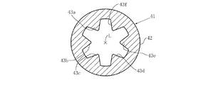
従来の呼吸気体供給用チューブの上述のような欠点を是正するようにした呼吸気体供給用チューブが、特許文献1に開示されている。図10に示すように、この特許文献1のチューブ41は、円筒状部42と、この円筒状部42の内周面にそれぞれ一体的に形成された例えば6本の突条部43a、43b、43c、43d、43e、43fとから構成されている。そして、これらの突条部43a〜43fが、上記円筒状部42の軸心方向Lに平行にかつ円周方向に順次ほぼ等間隔で延びている。また、チューブ41の横断面においては、各突条部43a〜43fは、先端側が直角である直角二等辺三角形に構成されている。
A breathing gas supply tube that corrects the above-described drawbacks of the conventional breathing gas supply tube is disclosed in Patent Document 1. As shown in FIG. 10, the
しかし、特許文献1の呼吸気体供給用チューブ41の場合には、鼻孔カニューラ装置などの使用中に、チューブ41が何らかの理由で強く押し潰されたり強く折り曲げられたりすると、図11に示すように、内部空間44がきわめて小さくなる。その理由は、突条部43a〜43fの先端部が、角張っているために、円筒状部42の内周面(すなわち、凹条部)に強く当接することによって、図11に示すように押し潰されてしまうからである。そして、このような現象は、チューブ41を構成しているプラスチックの硬度を小さくすればする程、顕著になる。したがって、特許文献1のチューブ41の場合にも、上記従来の呼吸気体供給用チューブの場合と同様に、このようなチューブ41を経由させて予め指示された流量でもって呼吸気体を鼻孔カニューラなどに供給することができない場合が生じることがある。
However, in the case of the breathing
本発明は、上記従来の呼吸気体供給用チューブや特許文献1の呼吸気体供給用チューブにおける上述のような欠点を、比較的簡単な構成でもって、効果的に是正し得るようにしたものである。 In the present invention, the above-described drawbacks of the conventional breathing gas supply tube and the breathing gas supply tube of Patent Document 1 can be effectively corrected with a relatively simple configuration. .
本発明は、その第1の観点においては、プラスチックから中空構造に構成されている呼吸気体供給用チューブにおいて、上記チューブが、HDA55〜HDA75(好ましくは、HDA60〜HDA70)の範囲の硬度を有するプラスチックから構成され、上記チューブが、筒状部と、この筒状部の内周面にそれぞれ一体的に形成された複数本(好ましくは、3〜8本、さらに好ましくは、4〜6本)の突条部とを備え、上記突条部のそれぞれが、上記筒状部のほぼ軸心方向に延びており、上記チューブの横断面においては、上記突条部の先端側が、上記チューブの軸心にほぼ向いているほぼ平坦な面に構成されていることを特徴とする呼吸気体供給用チューブに係るものである。なお、本文において、上記HDAとは、日本工業規格JIS K7215−1986「プラスチックのデュロメータ硬さ(A硬さ)の試験方法」に基づくデュロメータ硬さの記号である。 According to the first aspect of the present invention, in the breathing gas supply tube configured from a plastic to a hollow structure, the tube has a hardness in the range of HDA55 to HDA75 (preferably HDA60 to HDA70). The tube is composed of a cylindrical part and a plurality of (preferably 3 to 8, more preferably 4 to 6) integrally formed on the inner peripheral surface of the cylindrical part. Each of the ridges extends substantially in the axial direction of the tubular portion, and in the cross section of the tube, the tip side of the ridge is the axis of the tube. The present invention relates to a breathing gas supply tube, characterized in that the breathing gas supply tube is configured to have a substantially flat surface substantially facing the surface. In the text, the HDA is a symbol of durometer hardness based on Japanese Industrial Standard JIS K7215-1986 “Testing Method for Durometer Hardness (A Hardness) of Plastics”.
本発明の上記第1の観点においては、上記チューブの横断面においては、上記突条部のそれぞれの形状が基端側から先端側に向かってほぼ尻すぼまりのほぼ四角形状であるのが好ましい。また、本発明の上記第1の観点においては、上記チューブの横断面においては、上記筒状部の外径に対する上記突条部のそれぞれの上記ほぼ平坦な面の長さの比が、好ましくは、0.044〜0.14(さらに好ましくは、0.068〜0.10)の範囲である。また、本発明の上記第1の観点においては、上記チューブの横断面においては、上記筒状部の内径に対する、上記筒状部の軸心と上記突条部のそれぞれの上記ほぼ平坦な面との相互の間隔の比が、好ましくは、0.16〜0.48(さらに好ましくは、0.24〜0.40)の範囲である。さらに、本発明の上記第1の観点においては、上記突条部のそれぞれが、上記チューブの内周面の軸心方向にほぼ平行に延びているのが好ましい。 In the first aspect of the present invention, in the cross section of the tube, the shape of each of the protrusions is a substantially quadrangular shape that is substantially a ridge from the proximal end toward the distal end. preferable. In the first aspect of the present invention, in the cross section of the tube, the ratio of the length of the substantially flat surface of each of the protruding portions to the outer diameter of the cylindrical portion is preferably , 0.044 to 0.14 (more preferably 0.068 to 0.10). In the first aspect of the present invention, in the cross section of the tube, with respect to the inner diameter of the cylindrical portion, the axis of the cylindrical portion and the substantially flat surface of each of the protrusions, Is preferably in the range of 0.16 to 0.48 (more preferably 0.24 to 0.40). Furthermore, in the said 1st viewpoint of this invention, it is preferable that each of the said rib part is extended substantially parallel to the axial center direction of the internal peripheral surface of the said tube.
また、本発明は、その第2の観点においては、上記第1の観点における呼吸気体供給用チューブが、呼吸気体供給源から鼻孔カニューラまで呼吸気体を供給するための呼吸気体供給用チューブのうちの少なくとも一部分に用いられている。そして、本発明は、その第3の観点においては、上記第1の観点における呼吸気体供給用チューブが、呼吸気体供給源から口マスクまで呼吸気体を供給するための呼吸気体供給用チューブのうちの少なくとも一部分に用いられている。 Further, according to the second aspect of the present invention, in the second aspect, the respiratory gas supply tube according to the first aspect is a respiratory gas supply tube for supplying a respiratory gas from a respiratory gas supply source to a nostril cannula. Used at least in part. And in this 3rd viewpoint, this invention is the breathing gas supply tube in the said 1st viewpoint for the breathing gas supply tube for supplying the breathing gas from a breathing gas supply source to a mouth mask. Used at least in part.
本発明によれば、呼吸気体供給用チューブがHDA55〜HDA75の範囲の硬度を有するプラスチックから構成されているから、呼吸気体供給用チューブが十分な柔軟性を有している。したがって、このようなチューブが用いられている鼻孔カニューラ装置、口マスク装置などをカニューラ、口マスクなどの着用者に装着するときに、この装着やこれらの装置の取り扱いのいずれもが容易である。 According to the present invention, since the breathing gas supply tube is made of a plastic having a hardness in the range of HDA55 to HDA75, the breathing gas supply tube has sufficient flexibility. Accordingly, when a nostril cannula device, a mouth mask device, or the like in which such a tube is used is attached to a wearer such as a cannula or a mouth mask, both the attachment and the handling of these devices are easy.
また、呼吸気体供給用チューブの横断面においては、このチューブの筒状部の内周面に形成された突条部の先端側が、上記チューブの軸心にほぼ向いているほぼ平坦な面に構成されている。このために、鼻孔カニューラ装置、口マウス装置などの使用中に、酸素供給用チューブが何らかの理由で押し潰されたり折り曲げられたりしても、チューブの内部空間は或る程度の面積を確保され、しかも、このような面積の減少は、軸心方向には、部分的にしかすぎないから、呼吸気体供給用チューブの内部空間を流れる呼吸気体の流量が極端に少なくなる恐れがない。したがって、医師などによって予め指示された流量でもって呼吸気体を鼻孔カニューラに供給することに特別な困難性を生じる恐れがない。 Further, in the cross section of the breathing gas supply tube, the distal end side of the protrusion formed on the inner peripheral surface of the tubular portion of the tube is configured to be a substantially flat surface substantially facing the axis of the tube. Has been. For this reason, even if the oxygen supply tube is crushed or bent for some reason during use of a nostril cannula device, mouth mouth device, etc., the internal space of the tube is secured to some extent, In addition, since such a decrease in area is only partially in the axial direction, there is no possibility that the flow rate of the breathing gas flowing through the inner space of the breathing gas supply tube will become extremely small. Therefore, there is no possibility of causing a special difficulty in supplying the breathing gas to the nostril cannula with a flow rate previously instructed by a doctor or the like.
つぎに、本発明の一実施例を、「(1)鼻孔カニューラ装置の概略的構成」、「(2)呼吸気体供給用チューブの構成」および「(3)鼻孔カニューラ装置の作用および効果」に項分けして、図1〜図9を参照しつつ説明する。 Next, one embodiment of the present invention is described in “(1) Schematic configuration of nostril cannula device”, “(2) Configuration of breathing gas supply tube” and “(3) Action and effect of nostril cannula device”. The description will be made with reference to FIGS.
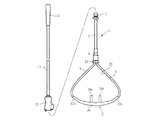
(1)鼻孔カニューラ装置の概略的構成
鼻孔カニューラ装置1は、図1および図2に示すように、中空構造でフレキシブルな鼻孔カニューラ2と、この鼻孔カニューラ2の両端部にそれらの一端部をそれぞれ連結されている呼吸気体供給用チューブとしての左右一対のフレキシブルで比較的短い第1の酸素供給用チューブ3、4と、これら一対の第1の酸素供給用チューブ3、4の他端部を呼吸気体供給用チューブとしての一本のフレキシブルで比較的短い第2の酸素供給用チューブ5の一端部に連結しているフレキシブルなY字形コネクタ6と、第2の酸素供給用チューブ5の他端部に取り付けられているコネクタ7とを備えている。また、鼻孔カニューラ装置1は、呼吸気体供給用チューブとしての一本のフレキシブルで比較的長い第3の酸素供給用チューブ11と、この第3の酸素供給用チューブ11の両端部にそれぞれ取り付けられたコネクタ12、13とをさらに備えている。そして、コネクタ12は、コネクタ7に着脱自在に連結される。また、コネクタ13は、鼻孔カニューラ装置1の使用時には、酸素タンクなどから成る呼吸気体供給装置(図示せず)に直接に接続されるか、あるいは、上記呼吸気体供給装置から延びている呼吸気体供給用チューブとしての第4の酸素供給用チューブ(図示せず)に接続される。
(1) Schematic Configuration of Nostril Cannula Device As shown in FIG. 1 and FIG. 2, the nostril cannula device 1 has a hollow nostril cannula 2 that is flexible and has one end portion at each end of the nostril cannula 2. A pair of left and right flexible and relatively short first oxygen supply tubes 3 and 4 as connected breathing gas supply tubes and the other ends of the pair of first oxygen supply tubes 3 and 4 breathe. A flexible Y-shaped connector 6 connected to one end portion of one flexible and relatively short second
カニューラ2は、図1および図2に示すように、低肺患者などのカニューラ着用者14(図2参照)の鼻15のすぐ下の形状に対応して多少前方に突出するように湾曲しているほぼ水平形状のチューブ状水平部16と、この水平部16の両端部からそれぞれ斜め上方外側に延びている左右一対のチューブ状連結部17a、17bと、水平部16の中間部分からカニューラ着用者14の左右の鼻孔18a、18b(図2参照)にそれぞれ対応するようにほぼ上方に延びている左右一対のチューブ状プロング部(すなわち、枝分れ部)19a、19bとを備えている。そして、上記一対の連結部17a、17bの上端部に左右一対の第1の酸素供給用チューブ3、4がそれぞれ連結されている。
As shown in FIGS. 1 and 2, the cannula 2 is curved so as to protrude slightly forward corresponding to the shape immediately below the
これら一対の第1の酸素供給用チューブ3、4の上端部は、図1および図2に示すように、リング21に共通に挿入されている。そして、カニューラ2の水平部16、左右一対の連結部17a、17b、左右一対の第1の酸素供給用チューブ3、4およびリング21から成るループ状部分によって囲まれる開口部22が形成されている。なお、この開口部22は、カニューラ着用者14の両耳23a、23bと顎部24とをほぼ取り囲む形状であって、この開口部22には、図2に示すように、鼻孔カニューラ装置1の使用時にカニューラ着用者14の両耳23a、23bと顎部24とがほぼ挿入される。そして、図2において、リング21を一対の第1の酸素供給用チューブ3、4に対して上昇させることによって、上記開口部22を小さくすることができるとともに、下降させることによって上記開口部22を大きくすることができる。
The upper ends of the pair of first oxygen supply tubes 3 and 4 are inserted into the
図1にそれぞれ示す鼻孔カニューラ2、左右一対の第1の酸素供給用チューブ3、4、Y字形コネクタ6、第2の酸素供給用チューブ5および第3の酸素供給用チューブ11は、軟質ポリ塩化ビニルなどの柔軟性に富み無臭で軽量なプラスチックから構成されていてよい。そして、第1の酸素供給用チューブ3、4は、第2および第3の酸素供給用チューブ5、11に較べて或る程度細いものであってよい。また、第2の酸素供給用チューブ5も、第3の酸素供給用チューブ11に較べて或る程度細いものであってよい。例えば、図示の実施例においては、第1の酸素供給用チューブ3、4の外径は、約3.3mmに構成され、第2の酸素供給用チューブ5の外径は、約5.5mmに構成され、第3の酸素供給用チューブ11の外径は、約8.0mmに構成されている。さらに、図1および図2から明らかなように、第1および第2の酸素供給用チューブ3〜5のそれぞれの長さは、数十cm程度であってよいが、第3の酸素供給用チューブ11は、2〜12m程度であってよい。
The nostril cannula 2, the pair of left and right first oxygen supply tubes 3 and 4, the Y-shaped connector 6, the second
(2)呼吸気体供給用チューブの構成
第2の酸素供給用チューブ5の形状、その他の構成は、図3〜図6に示されている。なお、第1の酸素供給用チューブ3、4は、太さおよび必要があれば長さが異なる点を除いて、形状、その他の構成が第2の酸素供給用チューブ5と実質的に同一であってよく、したがって、第2の酸素供給用チューブ5と実質的に相似形状(すなわち、図5に示す横断面形状、図4に示す縦断面形状などが実質的に相似形状)であってよい。また、第3の酸素供給用チューブ11は、長さおよび太さが異なる点を除いて、その構成が第2の酸素供給用チューブ5と実質的に同一であってよく、したがって、第2の酸素供給用チューブ5と実質的に相似形状(すなわち、図5に示す横断面形状、図4に示す縦断面形状などが実質的に相似形状)であってよい。したがって、以下において、第2の酸素供給用チューブ5について詳細に説明し、第1および第3の酸素供給用チューブ3、4、11についての説明は、必要に応じて省略する。
(2) Configuration of Respiratory Gas Supply Tube The shape of the second
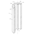
図3〜図6に示す第2の酸素供給用チューブ5(以下、「チューブ5」という。)は、基本的には、ほぼ円筒形状などのほぼ筒形状であってよい。ただし、チューブ5の内側表面は、単なる円柱面形状ではなくて、その軸心方向Lにほぼ平行にそのほぼ全長にわたってそれぞれ延びている複数本のほぼ柱状の突条部25a〜25dを備えている。したがって、チューブ5は、筒状部26と複数本の突条部25a〜25dとから構成されている。また、チューブ5の内側表面には、複数本の突条部25a〜25dの間にこれら複数本の突条部25a〜25dの本数と同数の凹条部27a〜27dがそれぞれ構成されている。そして、これら複数本の凹条部27a〜27dは、チューブ5の内周面の軸心方向Lにほぼ平行にそのほぼ全長にわたって延びている。なお、これらの突条部25a〜25d(換言すれば、上記凹条部27a〜27d)の本数は、図示の実施例においては4本であるが、本発明の目的を達成するためには、実用性の観点から見て一般的に、3〜8本の範囲であるのが好ましく、4〜6本の範囲であるのがさらに好ましい。また、上記複数本の突条部25a〜25d(換言すれば、凹条部27a〜27d)は、筒状部26の内周面にほぼ等間隔で配設されているのが好ましい。
The second oxygen supply tube 5 (hereinafter referred to as “
一方、図3〜図6に示すチューブ5の外側表面は、実質的には、単なる円柱面形状であってよい。ただし、この外側表面は、梨地状、その他の艶消し加工のようなエンボス処理を施されているのが好ましい。この場合、鼻孔カニューラ装置1の使用時におけるチューブ5の外側表面の滑りがよくなり、また、鼻孔カニューラ装置1の使用時におけるチューブ11の汚れが防止され、さらに、鼻孔カニューラ装置1の使用時におけるチューブ5の外側表面での光散乱によってチューブ5の外側表面がちらつくのを防止することができる。また、チューブ5の外側表面は、カニューラ装着者14などの好みに合わせて着色を施されることもできる。
On the other hand, the outer surface of the
本発明の特徴の1つは、チューブ5の硬度を特に小さくしたことである。具体的には、図示の実施例においては、チューブ5の硬度は、HDAで約67である。そして、本発明の目的を達成するためには、実用性の観点から見て一般的に、チューブ5の硬度は、HDA55〜HDA75の範囲であるのが好ましく、HDA60〜HDA70の範囲であるのがさらに好ましい。
One of the features of the present invention is that the hardness of the
各突条部25a〜25dの横断面の形状は、ほぼ長方形状、ほぼ台形状などのほぼ四角形状であってよいが、図示の実施例においては、図4〜図6に示すように、ほぼ等脚台形状である。この場合、図6に示す各突条部25a〜25dの横断面の形状において、基端側を下底31とし、先端側を上底32とすると、軸心Lから下底31に下した垂線Pは、交点P1および交点P2においてこれらの下底31および上底32とほぼ直角に交わる。そして、交点P1は、下底31の長さ方向におけるほぼ中心点であり、交点P2は、上底32の長さ方向におけるほぼ中心点である。また、上記等脚台形状の左右一対の脚33a、33bは、下底31から上底32に向かって垂線Pに近づく方向に傾斜している。したがって、本発明においては、各突条部25a〜25dの横断面の形状は、下底31から上底32に向かってほぼ尻すぼまりのほぼ四角形状であるのが好ましい。
The shape of the cross section of each of the
第1、第2および第3の酸素供給用チューブ3〜5、11の横断面の形状についての具体的な数値を記述すると、つぎの(a)項〜(z8)項に記載のとおりである。そして、つぎの(a)項〜(z8)項におけるかっこ内の数値は、第1の酸素供給用チューブ3、4および第3の酸素供給用チューブ11の横断面の形状についての具体的数値が第2の酸素供給用チューブ5の具体的数値とは異なっている場合において、第1の酸素供給用チューブ3、4および第3の酸素供給用チューブ11の横断面の形状についての具体的数値を示している。具体的には、上記カッコ内の数値のうちの「および」の前の数値は、第1の酸素供給用チューブ3、4についての数値である。また、「および」の後の数値は、第3の酸素供給用チューブ11についての数値である。
(a)チューブ(換言すれば、筒状部26)の外径D1:約5.5mm(約3.3mmおよび約8.0mm)、
(b)突条部25a〜25dが存在しないと考えたときのチューブの内径D2(すなわち、凹条部27におけるチューブまたは筒状部26の内径D2):約3.9mm(約2.35mmおよび約5.67mm)、
(c)突条部25a〜25dが存在しないと考えたときのチューブの肉厚(すなわち、凹条部27におけるチューブの肉厚であって、(外径D1−内径D2)×1/2):約0.8mm(約0.48mmおよび約1.16mm)、
(d)各突条部25a〜25dの下底31の長さ:約0.8mm(約0.48mmおよび約1.16mm)、
(e)各突条部25a〜25dの上底32の長さ:約0.48mm(約0.29mmおよび約0.07mm)、
(f)各突条部25a〜25dの各脚33a、33bの長さ:約0.75mm(約0.45mmおよび約1.09mm)、
(g)各突条部25a〜25dの上底32と下底31との相互の間隔(換言すれば、下底31からの突条部25a〜25dの高さ):約0.65mm(約0.39および約0.95mm)、
(h)軸心Lと各突条部25a〜25dの上底32との相互の間隔:約1.25mm(約0.75mmおよび約2.18mm)、
(i)垂線Pと各脚33a、33bとが相互に成す角度θ1:約12.5°、
(j)各凹条部27の底面34が軸心Lに対して成す角度θ2:約65°、
(k)各突条部25a〜25dの下底31および上底32のそれぞれが軸心Lに対して成す角度θ3およびθ4:約24°および約22°、
(l)上記(a)項に記載の外径D1に対する上記(b)項に記載の内径D2の比(D2/D1):約0.70、
(m)上記(a)項に記載の外径D1に対する上記(c)項に記載の肉厚の比:約0.15、
(n)上記(b)項に記載の内径D2に対する上記(c)項に記載の肉厚の比:約0.21、
(o)上記(a)項に記載の外径D1に対する上記(d)項に記載の長さの比:約0.15、
(p)上記(b)項に記載の内径D2に対する上記(d)項に記載の長さの比:約0.21、
(q)上記(a)項に記載の外径D1に対する上記(e)項に記載の長さの比:約0.09、
(r)上記(b)項に記載の内径D2に対する上記(e)項に記載の長さの比:約0.12、
(s)上記(a)項に記載の外径D1に対する上記(f)項に記載の長さの比:約0.14、
(t)上記(a)項に記載の外径D1に対する上記(g)項に記載の間隔の比:約0.12、
(u)上記(b)項に記載の内径D2に対する上記(g)項に記載の間隔の比:約0.17、
(v)上記(a)項に記載の外径D1に対する上記(h)項に記載の間隔の比:約0.23、
(w)上記(b)項に記載の内径D2に対する上記(h)項に記載の間隔の比:約0.32、
(x)上記(d)項に記載の長さに対する上記(e)項に記載の長さの比:約0.60、
(y)上記(d)項に記載の長さに対する上記(f)項に記載の長さの比:約0.94、
(z1)上記(d)項に記載の長さに対する上記(g)項に記載の間隔の比:約0.81、
(z2)上記(d)項に記載の長さに対する上記(h)項に記載の間隔の比:約1.56、
(z3)上記(e)項に記載の長さに対する上記(f)項に記載の長さの比:約1.55、
(z4)上記(e)項に記載の長さに対する上記(g)項に記載の間隔の比:約1.35、
(z5)上記(e)項に記載の長さに対する上記(h)項に記載の間隔の比:約2.60、
(z6)上記(f)項に記載の長さに対する上記(g)項に記載の間隔の比:約0.87、
(z7)上記(f)項に記載の長さに対する上記(h)項に記載の間隔の比:約1.67、および
(z8)上記(g)項に記載の間隔に対する上記(h)項に記載の間隔の比:約1.92。
Specific numerical values of the cross-sectional shapes of the first, second and third oxygen supply tubes 3 to 5 and 11 will be described as described in the following items (a) to (z8). . The numerical values in parentheses in the following items (a) to (z8) are specific numerical values for the cross-sectional shapes of the first oxygen supply tubes 3 and 4 and the third oxygen supply tube 11. When the specific values of the second
(A) The outer diameter D 1 of the tube (in other words, the cylindrical portion 26): about 5.5 mm (about 3.3 mm and about 8.0 mm),
The inner diameter D 2 of the tube when the (b)
(C) The thickness of the tube when it is considered that the
(D) The length of the
(E) Length of
(F) Length of each
(G) The distance between the
(H) A distance between the axis L and the
(I) Angle θ 1 formed between the perpendicular line P and each
(J) Angle θ 2 formed with respect to the axis L by the
(K) Angles θ 3 and θ 4 formed by the
(L) Ratio (D 2 / D 1 ) of the inner diameter D 2 described in the item (b) to the outer diameter D 1 described in the item (a) is about 0.70.
(M) The ratio of the wall thickness described in the above item (c) to the outer diameter D 1 described in the above item (a): about 0.15,
(N) (b) above thick described in section (c) to the inner diameter D 2 according to claim ratio: about 0.21,
(O) Ratio of the length described in the above item (d) to the outer diameter D 1 described in the above item (a): about 0.15,
(P) above (b) the ratio of the length (d) described above section to the inner diameter D 2 according to claim: about 0.21,
(Q) The ratio of the length described in the above item (e) to the outer diameter D 1 described in the above item (a): about 0.09,
(R) The ratio of the length according to the above paragraph (e) to the inner diameter D 2 according to the above paragraph (b): about 0.12,
(S) The ratio of the length described in the item (f) to the outer diameter D 1 described in the item (a) is about 0.14.
(T) The ratio of the spacing described in the above item (g) to the outer diameter D 1 described in the above item (a): about 0.12.
(U) the (b) above to the inner diameter D 2 according to claim (g) intervals according to claim ratio: about 0.17,
(V) The ratio of the spacing described in the item (h) to the outer diameter D 1 described in the item (a) is about 0.23.
(W) (b) above a ratio of spacing described above paragraph (h) to the inner diameter D 2 according to claim: about 0.32,
(X) The ratio of the length described in the above item (e) to the length described in the above item (d): about 0.60,
(Y) the ratio of the length described in item (f) to the length described in item (d) above: about 0.94;
(Z1) The ratio of the spacing described in the above (g) to the length described in the above (d): about 0.81
(Z2) The ratio of the distance described in the above item (h) to the length described in the above item (d): about 1.56,
(Z3) The ratio of the length described in the above item (f) to the length described in the above item (e): about 1.55;
(Z4) Ratio of the interval described in the above item (g) to the length described in the above item (e): about 1.35,
(Z5) The ratio of the interval described in the above item (h) to the length described in the above item (e): about 2.60,
(Z6) The ratio of the interval described in the above item (g) to the length described in the above item (f): about 0.87,
(Z7) The ratio of the interval described in the item (h) to the length described in the item (f): about 1.67, and (z8) the item (h) described above for the interval described in the item (g). The spacing ratio described in: about 1.92.
本発明を呼吸気体供給装置における呼吸気体供給用チューブに適用する場合における好ましい構成を上記(a)項〜(z8)項の記載にそれぞれ対応させて列挙すれば、実用性の観点から見て一般的に、つぎの(A)項〜(Z8)項に記載のとおりである。そして、本発明が適用される呼吸気体供給用チューブは、本発明の目的を達成するためには、実用性の観点から見て一般的に、これらの(A)項〜(Z8)項に記載の構成のうちのいずれか1つの構成または複数の構成もしくは全部の構成を備えているのが好ましい。なお、つぎの(A)項〜(Z8)項におけるかっこ内の数値のそれぞれは、さらに好ましい数値を示している。
(A)チューブの外径D1:2.48〜10.0mm(2.75〜9.3mm)の範囲、
(B)突条部25a〜25dが存在しないと考えたときのチューブの内径D2:約1.76〜7.09mm(1.99〜6.62mm)の範囲、
(C)突条部25a〜25dが存在しないと考えたときのチューブの肉厚:0.36〜1.45mm(0.40〜1.35mm)の範囲、
(D)各突条部25a〜25dの下底31の長さ:0.36〜1.45mm(0.40〜1.35mm)の範囲、
(E)各突条部25a〜25dの上底32の長さ:0.22〜0.88mm(0.24〜0.82mm)の範囲、
(F)各突条部25a〜25dの各脚33a、33bの長さ:0.34〜1.36mm(0.38〜1.27mm)の範囲、
(G)各突条部25a〜25dの上底32と下底31との相互の間隔:0.29〜1.19mm(0.32〜1.11mm)の範囲、
(H)軸心Lと各突条部25a〜25dの上底32との相互の間隔:0.56〜2.73mm(0.62〜2.54mm)の範囲、
(I)垂線Pと各脚33a、33bとが相互に成す角度θ1:6.2°〜18.8°(9.4°〜15.6°)の範囲、
(J)各凹条部27の底面34が軸心Lに対して成す角度θ2:32.5°〜97.5°(48.8°〜81.20°)の範囲、
(K)各突条部25a〜25dの下底31および上底32のそれぞれが軸心Lに対して成す角度θ3およびθ4:12°〜36°および11°〜33°(18°〜30°および16.5°〜27.5°)の範囲、
(L)上記(A)項に記載の外径D1に対する上記(B)項に記載の内径D2の比(D2/D1):0.52〜0.88(0.56〜0.84)の範囲、
(M)上記(A)項に記載の外径D1に対する上記(C)項に記載の肉厚の比:0.076〜0.22(0.10〜0.18)の範囲、
(N)上記(B)項に記載の内径D2に対する上記(C)項に記載の肉厚の比:0.10〜0.32(0.14〜0.26)の範囲、
(O)上記(A)項に記載の外径D1に対する上記(D)項に記載の長さの比:0.076〜0.22(0.10〜0.18)の範囲、
(P)上記(B)項に記載の内径D2に対する上記(D)項に記載の長さの比:0.10〜0.32(0.16〜0.26)の範囲、
(Q)上記(A)項に記載の外径D1に対する上記(E)項に記載の長さの比:0.044〜0.14(0.068〜0.10)の範囲、
(R)上記(B)項に記載の内径D2に対する上記(E)項に記載の長さの比:0.060〜0.18(0.08〜0.16)の範囲、
(S)上記(A)項に記載の外径D1に対する上記(F)項に記載の長さの比:0.070〜0.20(0.10〜0.18)の範囲、
(T)上記(A)項に記載の外径D1に対する上記(G)項に記載の間隔の比:0.06〜0.18(0.08〜0.16)の範囲、
(U)上記(B)項に記載の内径D2に対する上記(G)項に記載の間隔の比:0.085〜0.26(0.12〜0.22)の範囲、
(V)上記(A)項に記載の外径D1に対する上記(H)項に記載の間隔の比:0.12〜0.34(0.16〜0.30)の範囲、
(W)上記(B)項に記載の内径D2に対する上記(H)項に記載の間隔の比:0.16〜0.48(0.24〜0.40)の範囲、
(X)上記(D)項に記載の長さに対する上記(E)項に記載の長さの比:0.30〜0.90(0.44〜0.76)の範囲、
(Y)上記(D)項に記載の長さに対する上記(F)項に記載の長さの比:0.46〜1.42(0.70〜1.18)の範囲、
(Z1)上記(D)項に記載の長さに対する上記(G)項に記載の間隔の比:0.40〜1.22(0.60〜1.00)の範囲、
(Z2)上記(D)項に記載の長さに対する上記(H)項に記載の間隔の比:0.78〜2.34(1.16〜1.96)の範囲、
(Z3)上記(E)項に記載の長さに対する上記(F)項に記載の長さの比:0.78〜2.32(1.16〜1.94)の範囲、
(Z4)上記(E)項に記載の長さに対する上記(G)項に記載の間隔の比:0.68〜2.02(1.00〜1.70)の範囲、
(Z5)上記(E)項に記載の長さに対する上記(H)項に記載の間隔の比:1.30〜3.90(1.94〜3.26)の範囲、
(Z6)上記(F)項に記載の長さに対する上記(G)項に記載の間隔の比:0.44〜1.30(0.66〜1.08)の範囲、
(Z7)上記(F)項に記載の長さに対する上記(H)項に記載の間隔の比:0.84〜2.50(1.25〜2.08)の範囲、および
(Z8)上記(G)項に記載の間隔に対する上記(H)項に記載の間隔の比:0.96〜2.88(1.44〜2.40)の範囲。
When the present invention is applied to the breathing gas supply tube in the breathing gas supply device, preferable configurations are listed in correspondence with the descriptions in the above items (a) to (z8), respectively, from the viewpoint of practicality. Specifically, it is as described in the following items (A) to (Z8). In order to achieve the object of the present invention, the breathing gas supply tube to which the present invention is applied is generally described in the items (A) to (Z8) from the viewpoint of practicality. It is preferable that any one of the configurations described above or a plurality of configurations or all configurations are provided. In addition, each of the numerical value in the parenthesis in the following (A) term-(Z8) term has shown the more preferable numerical value.
(A) Tube outer diameter D 1 : in the range of 2.48 to 10.0 mm (2.75 to 9.3 mm),
(B) Inner diameter D 2 of the tube when it is considered that no
(C) Thickness of the tube when it is considered that the
(D) The length of the
(E) Length of the
(F) Length of each
(G) The distance between the
(H) Distance between the axial center L and the
(I) Angle θ 1 formed by the perpendicular line P and each
(J) Angle θ 2 formed by the
(K) Angles θ 3 and θ 4 formed by the
(L) (A) above the ratio of the inner diameter D 2 according to the above (B) section to the outer diameter D 1 of the described in item (D 2 / D 1): 0.52~0.88 (0.56~0 .84),
(M) (A) above thick according to the (C) section to the outer diameter D 1 of the described section ratio: range of 0.076 to 0.22 (0.10 to 0.18),
(N) above (B) of the thickness described above (C) section to the inner diameter D 2 according to claim ratio: range of 0.10 to 0.32 (0.14 to 0.26),
(O) (A) above the ratio of the length described above (D) term to the outer diameter D 1 of the described in the section: the range of 0.076 to 0.22 (0.10 to 0.18),
(P) above (B) the ratio of the length described above (D) term to the inner diameter D 2 according to claim: a range of from 0.10 to 0.32 (0.16 to 0.26),
(Q) The ratio of the length described in the above item (E) to the outer diameter D 1 described in the above item (A): a range of 0.044 to 0.14 (0.068 to 0.10),
(R) (B) above the ratio of the length described above (E) section to the inner diameter D 2 according to claim: a range of 0.060 to 0.18 (0.08 to 0.16),
(S) (A) above the ratio of the length described above (F) term for the outer diameter D 1 of the described in the section: the range of .070 to 0.20 (0.10 to 0.18),
(T) ratio of spacing described above (G) section to the outer diameter D 1 of the described above item (A): the range of 0.06 to 0.18 (from 0.08 to 0.16),
(U) above (B) of the gap according to the above (G) section to the inner diameter D 2 according to claim ratio: range of 0.085 to 0.26 (from 0.12 to 0.22),
(V) ratio of the distance according to the above (H) section to the outer diameter D 1 of the described above item (A): the range of from 0.12 to 0.34 (0.16 to 0.30),
(W) above (B) above to the inner diameter D 2 according to claim (H) ratio of the spacing of Item: range of .16 to .48 (.24-.40),
(X) the ratio of the length described in the above (E) to the length described in the above (D): a range of 0.30 to 0.90 (0.44 to 0.76);
(Y) The ratio of the length described in item (F) to the length described in item (D) above: in the range of 0.46 to 1.42 (0.70 to 1.18);
(Z1) Ratio of the interval described in the above (G) to the length described in the above (D): a range of 0.40 to 1.22 (0.60 to 1.00),
(Z2) The ratio of the interval described in the above item (H) to the length described in the above item (D): a range of 0.78 to 2.34 (1.16 to 1.96);
(Z3) The ratio of the length described in item (F) to the length described in item (E) above: in the range of 0.78 to 2.32 (1.16 to 1.94);
(Z4) Ratio of the spacing described in the above (G) to the length described in the above (E): a range of 0.68 to 2.02 (1.00 to 1.70);
(Z5) The ratio of the interval described in the above item (H) to the length described in the above item (E): a range of 1.30 to 3.90 (1.94 to 3.26);
(Z6) Ratio of the distance described in the above (G) to the length described in the above (F): a range of 0.44 to 1.30 (0.66 to 1.08),
(Z7) Ratio of the spacing described in the above (H) to the length described in the above (F): the range of 0.84 to 2.50 (1.25 to 2.08), and (Z8) above The ratio of the interval described in the above item (H) to the interval described in the item (G): 0.96 to 2.88 (1.44 to 2.40).
(3)鼻孔カニューラ装置の作用および効果
図1に示す鼻孔カニューラ装置1を用いて低肺患者などのカニューラ着用者14に呼吸気体供給装置からの呼吸気体を供給するときには、つぎに記述する手順で行えばよい。
(3) Action and Effect of Nasal Cannula Device When supplying the respiratory gas from the respiratory gas supply device to the cannula wearer 14 such as a low lung patient using the nostril cannula device 1 shown in FIG. Just do it.
まず、従来から一般的に知られているように、コネクタ13を呼吸気体供給源としての呼吸気体供給装置(例えば、酸素供給装置)に連結する。また、図2に示すように、鼻孔カニューラ2の左右一対のチューブ状プロング部19a、19bをカニューラ着用者14の左右の鼻孔18a、18bにそれぞれ挿入する。さらに、リング21を上下動させて、鼻孔カニューラ装置1の開口部22が、カニューラ着用者14の両耳23a、23bと顎部24とをほぼ取り囲むようにする。なお、上述のような幾つかの手順は、どのような順序で行われてもよい。そして、上述のような手順で鼻孔カニューラ装置1がカニューラ着用者14に装着されてから、呼吸気体供給装置から鼻孔カニューラ2に呼吸気体を供給すれば、従来から一般的に知られている鼻孔カニューラ装置の場合と同様に、カニューラ着用者14は、鼻孔カニューラ装置1(ひいては、鼻孔カニューラ2)を介して、呼吸気体の供給を受けることができる。
First, as is generally known, the
図1および図2に示す鼻孔カニューラ装置1においては、第1〜第3の酸素供給用チューブ3〜5、11の硬度がHDAで約67と小さいから、これらのチューブ3〜5、11は十分な柔軟性を有している。したがって、鼻孔カニューラ装置1をカニューラ着用者14に装着するときに、この装着や鼻孔カニューラ装置1の取扱いのいずれもが容易である。特に、カニューラ着用者14に最も近くに位置することになる第1の酸素供給用チューブ3、4が十分な柔軟性を有しているから、上述のように、鼻孔カニューラ装置1の開口部22にカニューラ着用者14の両耳23a、23bおよび顎部24を通す操作を非常にスムースに行うことができる。
In the nostril cannula device 1 shown in FIGS. 1 and 2, since the hardness of the first to third oxygen supply tubes 3 to 5 and 11 is as small as about 67 in HDA, these tubes 3 to 5 and 11 are sufficient. Flexibility. Therefore, when the nostril cannula device 1 is attached to the cannula wearer 14, both the attachment and the handling of the nostril cannula device 1 are easy. In particular, since the first oxygen supply tubes 3 and 4 that are located closest to the cannula wearer 14 have sufficient flexibility, the opening 22 of the nostril cannula device 1 as described above. In addition, the operation of passing the both
また、鼻孔カニューラ装置1の使用中に、第1〜第3の酸素供給用チューブ3〜5、11が何らかの理由で押し潰されたり折り曲げられたりしても、第1〜第3の酸素供給用チューブ3〜5、11の内部空間35を流れる呼吸気体の流量が極端に少なくなる恐れがない。第2の酸素供給用チューブ5を図示している図5〜図9を参照してこの点を説明すると、チューブ3〜5、11が押し潰されたり折れ曲がったりしていない場合には、中空構造を有するチューブ3〜5、11の内部空間35は、図5に示すように、突条部25a〜25dを除いてほぼ完全な円形に保持されている。そして、図5におけるa方向およびb方向からチューブ3〜5、11に力が加わると、図7に示すように、互いに対向する一対の突条部25b、25dのそれぞれの上底32が互いに当接するために、チューブ3〜5、11の内部空間35は、軸心方向Lには部分的に、多少減少する。また、図5におけるc方向およびd方向からチューブ3〜5、11に力が加わると、図8に示すように、互いに隣接する一対の突条部25a、25dのそれぞれの角部が互いに当接するとともに、互いに隣接する一対の突条部25b、25cのそれぞれの角部36が互いに当接するために、チューブ3〜5、11の内部空間35は、軸心方向Lには部分的に、多少減少する。さらに、図5におけるe方向およびf方向からチューブ3、5、11に力が加わると、図9に示すように、突条部25a〜25dの上底32が4つの凹条部27のうちのいずれか1つにそれぞれ当接するために、チューブ3、5、11の内部空間35は、軸心方向Lには部分的に、或る程度減少する。しかし、図7、図8および図9に示すいずれの場合にも、チューブ3、5、11の内部空間は或る程度の面積を確保されており、しかも、このような面積の減少は、軸心方向Lには、部分的にしかすぎない。したがって、呼吸気体を予め指示された流量でもって鼻孔カニューラ2に供給することに特別な困難性を生じる恐れがない。
Further, during use of the nostril cannula device 1, even if the first to third oxygen supply tubes 3 to 5 and 11 are crushed or bent for some reason, the first to third oxygen supply tubes are used. There is no fear that the flow rate of the breathing gas flowing through the
以上において、本発明の一実施例について詳細に説明したが、本発明は、上述の実施例に限定されるものではなく、特許請求の範囲に記載されている発明の趣旨に基づいて各種の変更および修正が可能である。 Although one embodiment of the present invention has been described in detail above, the present invention is not limited to the above-described embodiment, and various modifications can be made based on the gist of the invention described in the claims. And corrections are possible.
例えば、上述の実施例においては、本発明を鼻孔カニューラ装置に適用したが、本発明は、酸素マスク装置などの口マスク装置、その他の医療用などの装置や器具などにも適用することができる。 For example, in the above-described embodiments, the present invention is applied to a nostril cannula device, but the present invention can also be applied to a mouth mask device such as an oxygen mask device, and other medical devices and instruments. .
また、上述の実施例においては、各突条部25a〜25dは、チューブ3、5、11の内周面(換言すれば、筒状部26)の軸心方向Lにほぼ平行に延びている。しかし、各突条部25a〜25dは、上記軸心方向Lにほぼらせん状などにかつ互いにほぼ平行に延びていてもよい。
Moreover, in the above-mentioned Example, each
また、上述の実施例においては、各突条部25a〜25dの横断面の形状における左右一対の脚(換言すれば、左右一対の側面)33a、33bのそれぞれは、ほぼ直線状である。しかし、これらの脚33a、33bのそれぞれは、外側または内側に膨出するように円弧状などに湾曲していてもよく、また、折れ線状に折曲していてもよく、さらに、湾曲しかつ折曲していてもよい。
Moreover, in the above-mentioned Example, each of the left-right paired leg (in other words, a pair of left-right side surface) 33a, 33b in the shape of the cross section of each
3 第1の酸素供給用チューブ(呼吸気体供給用チューブ)
4 第1の酸素供給用チューブ(呼吸気体供給用チューブ)
5 第2の酸素供給用チューブ(呼吸気体供給用チューブ)
11 第3の酸素供給用チューブ(呼吸気体供給用チューブ)
25a ほぼ柱状の突条部
25b ほぼ柱状の突条部
25c ほぼ柱状の突条部
25d ほぼ柱状の突条部
26 筒状部
31 下底(基端側)
32 上底(基端側、ほぼ平坦な面)
L 軸心方向(軸心)
D1 外径
D2 内径
3 First oxygen supply tube (respiratory gas supply tube)
4 First oxygen supply tube (respiratory gas supply tube)
5 Second oxygen supply tube (respiratory gas supply tube)
11 Third oxygen supply tube (respiratory gas supply tube)
25a substantially
32 Upper base (base end side, almost flat surface)
L Axial direction (axial center)
D 1 outer diameter D 2 inner diameter
Claims (4)
(ア)HDA60〜HDA70の範囲の硬度を有するプラスチックから中空構造に構成されていること、
(イ)円筒状部と、この円筒状部の内周面にそれぞれ一体的にかつほぼ等間隔で形成された4本の突条部とを備えていること、
(ウ)上記突条部のそれぞれが、上記円筒状部のほぼ軸心方向に延びていること、
(エ)上記チューブの横断面においては、上記突条部の先端側が、上記チューブの軸心にほぼ向いているほぼ平坦な面に構成されていること、
(オ)上記チューブの横断面においては、上記突条部のそれぞれの形状が基端側から先端側に向かってほぼ尻すぼまりのほぼ四角形状であること、
(カ)上記突条部のそれぞれが、上記チューブの内周面の軸心方向にほぼ平行に延びていること、
(キ)上記チューブの横断面においては、上記円筒状部の外径に対する上記突条部のそれぞれの基端部を構成する下底の長さの比が、0.10〜0.18の範囲であること、
(ク)上記チューブの横断面においては、上記円筒状部の外径に対する上記突条部のそれぞれの上記ほぼ平坦な面の長さの比が、0.068〜0.10の範囲であること、
(ケ)上記チューブの横断面においては、上記円筒状部の内径に対する、上記円筒状部の軸心と上記突条部のそれぞれの上記ほぼ平坦な面との相互の間隔の比が、0.24〜0.40の範囲であること、
(コ)上記チューブの外径に対する上記チューブの内径の比が、0.56〜0.84の範囲であること、
をそれぞれその構成として備えていることを特徴とする鼻孔カニューラ装置。 At least a portion of the respiratory gas supply tubes used to supply the respiratory gas from the respiratory gas source to the nostril cannula,
(A) It is made of a plastic having a hardness in the range of HDA60 to HDA70 into a hollow structure,
(A) It is provided with a cylindrical portion and four protrusions formed integrally and at substantially equal intervals on the inner peripheral surface of the cylindrical portion,
(C) Each of the protrusions extends substantially in the axial direction of the cylindrical part,
(D) In the cross section of the tube, the tip side of the ridge is configured to be a substantially flat surface substantially facing the axis of the tube;
(E) In the cross section of the tube, the shape of each of the protrusions is a substantially quadrangular shape with a butt squeezing from the proximal end side to the distal end side;
(F) Each of the protrusions extends substantially parallel to the axial direction of the inner peripheral surface of the tube.
(G) In the cross section of the tube, the ratio of the length of the lower base constituting each base end portion of the protruding portion to the outer diameter of the cylindrical portion is in the range of 0.10 to 0.18. Being
(H) In the cross section of the tube, the ratio of the length of the substantially flat surface of each of the protrusions to the outer diameter of the cylindrical portion is in the range of 0.068 to 0.10. ,
(K) In the cross section of the tube, the ratio of the distance between the axial center of the cylindrical portion and the substantially flat surface of each of the protruding portions relative to the inner diameter of the cylindrical portion is 0. In the range of 24-0.40,
(Ko) The ratio of the inner diameter of the tube to the outer diameter of the tube is in the range of 0.56 to 0.84.
Nasal cannula device characterized in that it comprises as its constituent, respectively.
(サ)上記チューブの外径が、2.75〜9.3mmの範囲であること、(S) The outer diameter of the tube is in the range of 2.75 to 9.3 mm,
(シ)上記突条部が存在しないと考えたときの上記チューブの内径が、1.99〜6.62mmの範囲であること、(F) The inner diameter of the tube when the protrusion is not present is in the range of 1.99 to 6.62 mm;
(ス)上記突条部が存在しないと考えたときの上記チューブの肉厚が、0.40〜1.35mmの範囲であること、(Su) The thickness of the tube when the protrusion is not present is in the range of 0.40 to 1.35 mm,
(セ)上記チューブの横断面においては、上記円筒状部の上記軸心から上記下底に下した垂線と上記突条部の左右一対の脚のそれぞれとが相互に成す角度が、9.4°〜15.6°の範囲であること、(C) In the cross section of the tube, the angle formed between the perpendicular line extending from the axial center of the cylindrical portion to the lower bottom and the pair of left and right legs of the protruding portion is 9.4. In the range of ° to 15.6 °,
(ソ)上記4本の突条部の間にそれぞれ存在する凹条部のそれぞれの底面が上記円筒状部の上記軸心に対して成す角度が48.8°〜81.20°の範囲であること、(G) The angle formed by the bottom surface of each of the concave portions existing between the four protrusions with respect to the axis of the cylindrical portion is in the range of 48.8 ° to 81.20 °. There is,
をそれぞれ構成として備えていることを特徴とする請求項1に記載の鼻孔カニューラ装置。The nostril cannula device according to claim 1, wherein the nostril cannula device is provided.
(ア)HDA60〜HDA70の範囲の硬度を有するプラスチックから中空構造に構成されていること、
(イ)円筒状部と、この円筒状部の内周面にそれぞれ一体的にかつほぼ等間隔で形成された4本の突条部とを備えていること、
(ウ)上記突条部のそれぞれが、上記円筒状部のほぼ軸心方向に延びていること、
(エ)上記チューブの横断面においては、上記突条部の先端側が、上記チューブの軸心にほぼ向いているほぼ平坦な面に構成されていること、
(オ)上記チューブの横断面においては、上記突条部のそれぞれの形状が基端側から先端側に向かってほぼ尻すぼまりのほぼ四角形状であること、
(カ)上記突条部のそれぞれが、上記チューブの内周面の軸心方向にほぼ平行に延びていること、
(キ)上記チューブの横断面においては、上記円筒状部の外径に対する上記突条部のそれぞれの基端部を構成する下底の長さの比が、0.10〜0.18の範囲であること、
(ク)上記チューブの横断面においては、上記円筒状部の外径に対する上記突条部のそれぞれの上記ほぼ平坦な面の長さの比が、0.068〜0.10の範囲であること、
(ケ)上記チューブの横断面においては、上記円筒状部の内径に対する、上記円筒状部の軸心と上記突条部のそれぞれの上記ほぼ平坦な面との相互の間隔の比が、0.24〜0.40の範囲であること、
(コ)上記チューブの外径に対する上記チューブの内径の比が、0.56〜0.84の範囲であること、
をそれぞれその構成として備えていることを特徴とする口マスク装置。 At least a portion of the breathing gas supply tubes used to deliver the breathing gas from the breathing gas source to the mouth mask,
(A) It is made of a plastic having a hardness in the range of HDA60 to HDA70 into a hollow structure,
(A) It is provided with a cylindrical portion and four protrusions formed integrally and at substantially equal intervals on the inner peripheral surface of the cylindrical portion,
(C) Each of the protrusions extends substantially in the axial direction of the cylindrical part,
(D) In the cross section of the tube, the tip side of the ridge is configured to be a substantially flat surface substantially facing the axis of the tube;
(E) In the cross section of the tube, the shape of each of the protrusions is a substantially quadrangular shape with a butt squeezing from the proximal end side to the distal end side;
(F) Each of the protrusions extends substantially parallel to the axial direction of the inner peripheral surface of the tube.
(G) In the cross section of the tube, the ratio of the length of the lower base constituting each base end portion of the protruding portion to the outer diameter of the cylindrical portion is in the range of 0.10 to 0.18. Being
(H) In the cross section of the tube, the ratio of the length of the substantially flat surface of each of the protrusions to the outer diameter of the cylindrical portion is in the range of 0.068 to 0.10. ,
(K) In the cross section of the tube, the ratio of the distance between the axial center of the cylindrical portion and the substantially flat surface of each of the protruding portions relative to the inner diameter of the cylindrical portion is 0. In the range of 24-0.40,
(Ko) The ratio of the inner diameter of the tube to the outer diameter of the tube is in the range of 0.56 to 0.84.
Each of the mouth mask devices characterized by comprising as a component thereof .
(サ)上記チューブの外径が、2.75〜9.3mmの範囲であること、(S) The outer diameter of the tube is in the range of 2.75 to 9.3 mm,
(シ)上記突条部が存在しないと考えたときの上記チューブの内径が、1.99〜6.62mmの範囲であること、(F) The inner diameter of the tube when the protrusion is not present is in the range of 1.99 to 6.62 mm;
(ス)上記突条部が存在しないと考えたときの上記チューブの肉厚が、0.40〜1.35mmの範囲であること、(Su) The thickness of the tube when the protrusion is not present is in the range of 0.40 to 1.35 mm,
(セ)上記チューブの横断面においては、上記円筒状部の上記軸心から上記下底に下した垂線と上記突条部の左右一対の脚のそれぞれとが相互に成す角度が、9.4°〜15.6°の範囲であること、(C) In the cross section of the tube, the angle formed between the perpendicular line extending from the axial center of the cylindrical portion to the lower bottom and the pair of left and right legs of the protruding portion is 9.4. In the range of ° to 15.6 °,
(ソ)上記4本の突条部の間にそれぞれ存在する凹条部のそれぞれの底面が上記円筒状部の上記軸心に対して成す角度が48.8°〜81.20°の範囲であること、(G) The angle formed by the bottom surface of each of the concave portions existing between the four protrusions with respect to the axis of the cylindrical portion is in the range of 48.8 ° to 81.20 °. There is,
をそれぞれ構成として備えていることを特徴とする請求項3に記載の口マスク装置。The mouth mask device according to claim 3, wherein the mouth mask device is provided as a configuration.
Priority Applications (1)
| Application Number | Priority Date | Filing Date | Title |
|---|---|---|---|
| JP2009160740A JP5469934B2 (en) | 2009-07-07 | 2009-07-07 | Nostril cannula device and mouth mask device |
Applications Claiming Priority (1)
| Application Number | Priority Date | Filing Date | Title |
|---|---|---|---|
| JP2009160740A JP5469934B2 (en) | 2009-07-07 | 2009-07-07 | Nostril cannula device and mouth mask device |
Publications (2)
| Publication Number | Publication Date |
|---|---|
| JP2011015731A JP2011015731A (en) | 2011-01-27 |
| JP5469934B2 true JP5469934B2 (en) | 2014-04-16 |
Family
ID=43594009
Family Applications (1)
| Application Number | Title | Priority Date | Filing Date |
|---|---|---|---|
| JP2009160740A Active JP5469934B2 (en) | 2009-07-07 | 2009-07-07 | Nostril cannula device and mouth mask device |
Country Status (1)
| Country | Link |
|---|---|
| JP (1) | JP5469934B2 (en) |
Families Citing this family (3)
| Publication number | Priority date | Publication date | Assignee | Title |
|---|---|---|---|---|
| JP5872350B2 (en) * | 2012-03-28 | 2016-03-01 | 日本メディカルネクスト株式会社 | Nostril cannula |
| JP6305369B2 (en) | 2014-09-05 | 2018-04-04 | アトムメディカル株式会社 | Cannula equipment |
| JP2017093905A (en) * | 2015-11-26 | 2017-06-01 | 信越ポリマー株式会社 | Tube instrument for being inserted into nasal cavity |
Family Cites Families (3)
| Publication number | Priority date | Publication date | Assignee | Title |
|---|---|---|---|---|
| JPH0346768Y2 (en) * | 1987-03-18 | 1991-10-03 | ||
| JPH0611748U (en) * | 1992-07-16 | 1994-02-15 | 忠夫 真辺 | Drain with protrusions on the inner wall and grooves on the outer wall |
| JP2007506480A (en) * | 2003-08-18 | 2007-03-22 | ワンドカ,アンソニー・ディ | Methods and apparatus for non-invasive ventilation with a nasal interface |
-
2009
- 2009-07-07 JP JP2009160740A patent/JP5469934B2/en active Active
Also Published As
| Publication number | Publication date |
|---|---|
| JP2011015731A (en) | 2011-01-27 |
Similar Documents
| Publication | Publication Date | Title |
|---|---|---|
| US7987850B2 (en) | Nasal interface prong device | |
| US7730888B2 (en) | Nasopharyngeal airway device and method of use | |
| JP2018108455A (en) | Artificial airway device | |
| AU2014330888B2 (en) | Artificial airway device | |
| JP2017508519A (en) | System and method for facilitating intubation | |
| JP2010142651A (en) | Laryngeal mask airway device | |
| WO2012042219A1 (en) | Artificial airway device | |
| US10342526B2 (en) | Airway assist device and method | |
| JP5469934B2 (en) | Nostril cannula device and mouth mask device | |
| JP2011030863A (en) | Endotracheal tube introducer | |
| KR102620443B1 (en) | Gas sampling interface and gas sampling tip | |
| US7955256B2 (en) | Laryngoscope blade | |
| US20210023320A1 (en) | Laryngeal mask airway | |
| TW201317015A (en) | Laryngeal mask | |
| US20220323701A1 (en) | Expiration system and ball joint for a patient interface | |
| JP2018518305A (en) | Tongue lifting propulsion tool and operation method thereof | |
| CN106075687B (en) | A kind of double-lumen catheter | |
| JP6373136B2 (en) | Medical removal tool | |
| CN220236849U (en) | Disposable hard bronchoscope | |
| CN210020734U (en) | Improved straight tube oropharynx breather tube | |
| US20240009414A1 (en) | Airway device | |
| CN215995194U (en) | Disposable stomach tube trachea cannula fixer | |
| TWI747981B (en) | Respiratory gas delivery and sampling system | |
| JP6412438B2 (en) | Intubation forceps |
Legal Events
| Date | Code | Title | Description |
|---|---|---|---|
| A621 | Written request for application examination |
Free format text: JAPANESE INTERMEDIATE CODE: A621 Effective date: 20120412 |
|
| A131 | Notification of reasons for refusal |
Free format text: JAPANESE INTERMEDIATE CODE: A131 Effective date: 20130515 |
|
| A977 | Report on retrieval |
Free format text: JAPANESE INTERMEDIATE CODE: A971007 Effective date: 20130516 |
|
| A521 | Request for written amendment filed |
Free format text: JAPANESE INTERMEDIATE CODE: A523 Effective date: 20130626 |
|
| TRDD | Decision of grant or rejection written | ||
| A01 | Written decision to grant a patent or to grant a registration (utility model) |
Free format text: JAPANESE INTERMEDIATE CODE: A01 Effective date: 20140107 |
|
| A61 | First payment of annual fees (during grant procedure) |
Free format text: JAPANESE INTERMEDIATE CODE: A61 Effective date: 20140203 |
|
| R150 | Certificate of patent or registration of utility model |
Ref document number: 5469934 Country of ref document: JP Free format text: JAPANESE INTERMEDIATE CODE: R150 Free format text: JAPANESE INTERMEDIATE CODE: R150 |
|
| R250 | Receipt of annual fees |
Free format text: JAPANESE INTERMEDIATE CODE: R250 |
|
| R250 | Receipt of annual fees |
Free format text: JAPANESE INTERMEDIATE CODE: R250 |
|
| R250 | Receipt of annual fees |
Free format text: JAPANESE INTERMEDIATE CODE: R250 |
|
| R250 | Receipt of annual fees |
Free format text: JAPANESE INTERMEDIATE CODE: R250 |
|
| R250 | Receipt of annual fees |
Free format text: JAPANESE INTERMEDIATE CODE: R250 |
|
| R250 | Receipt of annual fees |
Free format text: JAPANESE INTERMEDIATE CODE: R250 |
|
| R250 | Receipt of annual fees |
Free format text: JAPANESE INTERMEDIATE CODE: R250 |
|
| R250 | Receipt of annual fees |
Free format text: JAPANESE INTERMEDIATE CODE: R250 |