JP5469293B2 - Method for image reconstruction using a hybrid computed tomography detector - Google Patents
Method for image reconstruction using a hybrid computed tomography detector Download PDFInfo
- Publication number
- JP5469293B2 JP5469293B2 JP2006343734A JP2006343734A JP5469293B2 JP 5469293 B2 JP5469293 B2 JP 5469293B2 JP 2006343734 A JP2006343734 A JP 2006343734A JP 2006343734 A JP2006343734 A JP 2006343734A JP 5469293 B2 JP5469293 B2 JP 5469293B2
- Authority
- JP
- Japan
- Prior art keywords
- image
- measurement data
- data
- component
- reconstruction
- Prior art date
- Legal status (The legal status is an assumption and is not a legal conclusion. Google has not performed a legal analysis and makes no representation as to the accuracy of the status listed.)
- Expired - Fee Related
Links
Images


Classifications
-
- G—PHYSICS
- G01—MEASURING; TESTING
- G01N—INVESTIGATING OR ANALYSING MATERIALS BY DETERMINING THEIR CHEMICAL OR PHYSICAL PROPERTIES
- G01N23/00—Investigating or analysing materials by the use of wave or particle radiation, e.g. X-rays or neutrons, not covered by groups G01N3/00 – G01N17/00, G01N21/00 or G01N22/00
- G01N23/02—Investigating or analysing materials by the use of wave or particle radiation, e.g. X-rays or neutrons, not covered by groups G01N3/00 – G01N17/00, G01N21/00 or G01N22/00 by transmitting the radiation through the material
- G01N23/04—Investigating or analysing materials by the use of wave or particle radiation, e.g. X-rays or neutrons, not covered by groups G01N3/00 – G01N17/00, G01N21/00 or G01N22/00 by transmitting the radiation through the material and forming images of the material
- G01N23/046—Investigating or analysing materials by the use of wave or particle radiation, e.g. X-rays or neutrons, not covered by groups G01N3/00 – G01N17/00, G01N21/00 or G01N22/00 by transmitting the radiation through the material and forming images of the material using tomography, e.g. computed tomography [CT]
-
- A—HUMAN NECESSITIES
- A61—MEDICAL OR VETERINARY SCIENCE; HYGIENE
- A61B—DIAGNOSIS; SURGERY; IDENTIFICATION
- A61B6/00—Apparatus or devices for radiation diagnosis; Apparatus or devices for radiation diagnosis combined with radiation therapy equipment
- A61B6/02—Arrangements for diagnosis sequentially in different planes; Stereoscopic radiation diagnosis
- A61B6/03—Computed tomography [CT]
- A61B6/032—Transmission computed tomography [CT]
-
- A—HUMAN NECESSITIES
- A61—MEDICAL OR VETERINARY SCIENCE; HYGIENE
- A61B—DIAGNOSIS; SURGERY; IDENTIFICATION
- A61B6/00—Apparatus or devices for radiation diagnosis; Apparatus or devices for radiation diagnosis combined with radiation therapy equipment
- A61B6/42—Arrangements for detecting radiation specially adapted for radiation diagnosis
- A61B6/4208—Arrangements for detecting radiation specially adapted for radiation diagnosis characterised by using a particular type of detector
- A61B6/4241—Arrangements for detecting radiation specially adapted for radiation diagnosis characterised by using a particular type of detector using energy resolving detectors, e.g. photon counting
-
- A—HUMAN NECESSITIES
- A61—MEDICAL OR VETERINARY SCIENCE; HYGIENE
- A61B—DIAGNOSIS; SURGERY; IDENTIFICATION
- A61B6/00—Apparatus or devices for radiation diagnosis; Apparatus or devices for radiation diagnosis combined with radiation therapy equipment
- A61B6/48—Diagnostic techniques
- A61B6/482—Diagnostic techniques involving multiple energy imaging
-
- G—PHYSICS
- G01—MEASURING; TESTING
- G01N—INVESTIGATING OR ANALYSING MATERIALS BY DETERMINING THEIR CHEMICAL OR PHYSICAL PROPERTIES
- G01N2223/00—Investigating materials by wave or particle radiation
- G01N2223/40—Imaging
- G01N2223/419—Imaging computed tomograph
-
- Y—GENERAL TAGGING OF NEW TECHNOLOGICAL DEVELOPMENTS; GENERAL TAGGING OF CROSS-SECTIONAL TECHNOLOGIES SPANNING OVER SEVERAL SECTIONS OF THE IPC; TECHNICAL SUBJECTS COVERED BY FORMER USPC CROSS-REFERENCE ART COLLECTIONS [XRACs] AND DIGESTS
- Y10—TECHNICAL SUBJECTS COVERED BY FORMER USPC
- Y10S—TECHNICAL SUBJECTS COVERED BY FORMER USPC CROSS-REFERENCE ART COLLECTIONS [XRACs] AND DIGESTS
- Y10S378/00—X-ray or gamma ray systems or devices
- Y10S378/901—Computer tomography program or processor
Landscapes
- Health & Medical Sciences (AREA)
- Life Sciences & Earth Sciences (AREA)
- Engineering & Computer Science (AREA)
- Medical Informatics (AREA)
- Pathology (AREA)
- General Health & Medical Sciences (AREA)
- Physics & Mathematics (AREA)
- Nuclear Medicine, Radiotherapy & Molecular Imaging (AREA)
- Radiology & Medical Imaging (AREA)
- Heart & Thoracic Surgery (AREA)
- Veterinary Medicine (AREA)
- Biomedical Technology (AREA)
- High Energy & Nuclear Physics (AREA)
- Molecular Biology (AREA)
- Surgery (AREA)
- Animal Behavior & Ethology (AREA)
- Biophysics (AREA)
- Public Health (AREA)
- Optics & Photonics (AREA)
- Pulmonology (AREA)
- Theoretical Computer Science (AREA)
- Chemical & Material Sciences (AREA)
- Analytical Chemistry (AREA)
- Biochemistry (AREA)
- General Physics & Mathematics (AREA)
- Immunology (AREA)
- Apparatus For Radiation Diagnosis (AREA)
Description
本発明は、一般的に云えば、画像再構成に関するものである。具体的には、本発明は、ハイブリッド型コンピュータ断層撮影(CT)検出器を使用して画像再構成を行うための手法に関するものである。 The present invention relates generally to image reconstruction. Specifically, the present invention relates to a technique for performing image reconstruction using a hybrid computed tomography (CT) detector.
CTイメージング・システムは様々な角度から患者を通り抜けたX線ビームの強度を測定する。患者を撮影する角度範囲が充分であると、走査対象物の内部構造を明らかにする断面画像を形成することができる。これらの画像は典型的には陰極線管又はコンピュータ画面上に表示され、またフィルム上に印刷又は再生することもできる。また、仮想3D画像をCT検査によって生成することもできる。 CT imaging systems measure the intensity of an x-ray beam that has passed through a patient from various angles. If the angle range for imaging the patient is sufficient, a cross-sectional image that reveals the internal structure of the scanning object can be formed. These images are typically displayed on a cathode ray tube or computer screen and can also be printed or reproduced on film. A virtual 3D image can also be generated by CT examination.
CTスキャナはX線源からX線ビームを投射して減弱性対象物(例えば、患者)に通すように動作する。X線ビームは、検出器の構成、最適な患者照射量、又は他の因子に依存して、線源と対象物との間でコリメートされて扇形又は円錐形ビームを形成する。次いで、一組の検出器素子が減弱したビームを検出する。検出器素子はX線ビームの強度に基づいた信号を発生する。このように測定されたデータは、X線通路に沿った対象物の減弱係数の線積分を表すように処理される。処理後のデータは典型的には「投影」と呼ばれる。フィルタ補正逆投影法のような再構成手法を使用することによって、これらの投影から断面画像が形成される。隣接した断面画像を一緒に表示して、対象物又は患者の被撮像領域を表すボリューム(立体物)を描くことができる。 A CT scanner operates to project an X-ray beam from an X-ray source and pass it through an attenuated object (eg, a patient). The x-ray beam is collimated between the source and the object to form a fan or cone beam, depending on the detector configuration, optimal patient dose, or other factors. A set of detector elements then detects the attenuated beam. The detector element generates a signal based on the intensity of the x-ray beam. The data measured in this way is processed to represent the line integral of the attenuation coefficient of the object along the X-ray path. The processed data is typically called “projection”. By using reconstruction techniques such as filtered backprojection, cross-sectional images are formed from these projections. The adjacent cross-sectional images can be displayed together to draw a volume (three-dimensional object) representing the object or the imaged area of the patient.
当業者に理解されるように、物質の減弱係数は、X線が所与の長さの物質を通過するときに生じることのある2つの別々の事象の関数である。第1の事象はコンプトン散乱として知られており、これは所与の長さの物質を通過するX線フォトンが散乱する現象、すなわち、元々のビーム経路から方向が変わる現象を表し、その結果としてエネルギが変化する。第2の事象は光電吸収として知られており、これは所与の長さの物質を通過するX線フォトンが該物質によって吸収される現象を表す。 As will be appreciated by those skilled in the art, a material's attenuation coefficient is a function of two separate events that can occur when an x-ray passes through a given length of material. The first event is known as Compton scattering, which represents the phenomenon of X-ray photons passing through a given length of material, ie, a phenomenon that changes direction from the original beam path. Energy changes. The second event is known as photoelectric absorption, which represents the phenomenon where X-ray photons passing through a given length of material are absorbed by the material.
直ぐ予想されるように、異なる物質はそれらの散乱及び吸収特性が異なり、その結果、異なる物質では減弱係数が異なる。具体的に述べると、コンプトン散乱の確率はその一部が被撮像物質の電子密度に依存し、また光電吸収の確率はその一部が被撮像物質の原子番号に依存する、すなわち、原子番号が大きくなると、吸収の可能性が大きくなる。更に、コンプトン散乱効果及び光電吸収は共にX線ビームのエネルギにも部分的に依存する。結果として、相異なる物質は、該物質によるX線減弱度における光電吸収及びコンプトン散乱効果の相対的な重要性に基づいて互いから区別することができる。具体的に述べると、2つ以上のX線エネルギ又はスペクトル、すなわち、マルチエネルギ又はマルチスペクトルCTにおいて物質で生じる減弱の測定は、用いられるX線エネルギ・レベルにおいて物質についてそれぞれのコンプトン散乱及び光電吸収の寄与分を定量化できるようにすることができる。 As expected immediately, different materials have different scattering and absorption properties, so that different materials have different attenuation factors. Specifically, the probability of Compton scattering partially depends on the electron density of the imaged material, and the probability of photoelectric absorption partially depends on the atomic number of the imaged material, that is, the atomic number is As it grows, the potential for absorption increases. Furthermore, both the Compton scattering effect and photoelectric absorption are also partially dependent on the energy of the X-ray beam. As a result, different materials can be distinguished from each other based on the relative importance of photoelectric absorption and Compton scattering effects in the X-ray attenuation by the material. Specifically, the measurement of attenuation that occurs in a material in more than one X-ray energy or spectrum, ie multi-energy or multi-spectral CT, can be determined by measuring the respective Compton scattering and photoelectric absorption for the material at the X-ray energy level used. Can be quantified.
マルチエネルギCT走査は、2つの異なる実効X線エネルギによるX線透過測定値を取得するプロセスに関する。しばしば、これは2つ以上の管電圧(二重kVp)における測定値を組み合わせることによって達成される。2つの異なる既知の実効エネルギの2つの測定値を使用して、組織及び/又は物質組成について情報を抽出することが可能である。共通の方策は、対象物を、骨と等価な吸収体と、軟組織と等価な吸収体とに分離することである。マルチエネルギ走査は、診断用X線エネルギ範囲内で、本質的に全てのX線相互作用が光電吸収又はコンプトン散乱のいずれかを介するものであり、これらが異なるエネルギ依存性を持つと云う原理に基づいている。これらは次いで、原子番号及び電子密度に異なる依存性を持つ。前に述べたように、コンプトン散乱の確率はX線エネルギ及び電子密度に依存し、他方、光電吸収の確率は原子番号につれて急激に増大し且つフォトン・エネルギの増大につれて急激に減少する。 Multi-energy CT scans relate to the process of obtaining x-ray transmission measurements with two different effective x-ray energies. Often this is accomplished by combining measurements at two or more tube voltages (double kVp). Two measurements of two different known effective energies can be used to extract information about tissue and / or material composition. A common strategy is to separate the object into an absorber equivalent to bone and an absorber equivalent to soft tissue. Multi-energy scanning is based on the principle that within the diagnostic X-ray energy range, essentially all X-ray interactions are via either photoelectric absorption or Compton scattering, which have different energy dependencies. Is based. They then have different dependencies on atomic number and electron density. As previously mentioned, the probability of Compton scattering depends on the X-ray energy and electron density, while the probability of photoelectric absorption increases rapidly with atomic number and decreases rapidly with increasing photon energy.
エネルギ弁別(ED)検出器が一般にマルチエネルギCT走査システムに使用されて、例えば、高エネルギ信号及び低エネルギ信号のような、2つ以上のエネルギ間隔に対応する2つ以上の信号を発生することによって、検出したフォトンのエネルギ分布に関する情報を提供する。当業者に理解されるように、ED検出器は、撮像ボリューム内の物質(1つ又は複数)の物理的な密度及び/又は実効原子番号に関する情報と関連して空間情報を提供する。空間情報並びに密度情報及び/又は原子番号情報を使用して、オペレータは、原子番号又は密度が異なっている骨、軟組織又は造影剤のような選択された物質を主に表示する画像を再構成することができる。このように、主に関心のある物質を表示する骨画像、軟組織画像、造影剤画像などを再構成することができる。これらの画像は次に関心のある物質のボリューム・レンダリングを形成するように関連付けることができ、これは骨の密度又は劣化、軟組織の損傷、造影剤の灌流などを決定する際に有用であると思われる。ED検出器は、単一線源エネルギで、又は二重kVpのCTシステムと同様な複数線源エネルギで使用することができる。 Energy discrimination (ED) detectors are commonly used in multi-energy CT scanning systems to generate two or more signals corresponding to two or more energy intervals, such as, for example, a high energy signal and a low energy signal. Provides information on the energy distribution of the detected photons. As will be appreciated by those skilled in the art, the ED detector provides spatial information in conjunction with information regarding the physical density and / or effective atomic number of the material (s) within the imaging volume. Using the spatial information and density information and / or atomic number information, the operator reconstructs an image that primarily displays the selected material, such as bone, soft tissue, or contrast agent, having different atomic numbers or densities. be able to. In this way, a bone image, a soft tissue image, a contrast agent image, and the like that mainly display a substance of interest can be reconstructed. These images can then be correlated to form a volume rendering of the material of interest, which is useful in determining bone density or degradation, soft tissue damage, contrast agent perfusion, etc. Seem. The ED detector can be used with single source energy or with multiple source energy similar to a dual kVp CT system.
他方、従来のCT検出器はエネルギ積算(EI)検出器と呼ばれる。EI検出器は、各ビュー(view)において吸収されたX線エネルギの総量に比例する電子信号を発生する。この結果、検出器信号は個々のフォトンのエネルギ分布に関する情報を何ら含んでいない。 On the other hand, conventional CT detectors are called energy integrating (EI) detectors. The EI detector generates an electronic signal that is proportional to the total amount of x-ray energy absorbed in each view. As a result, the detector signal does not contain any information regarding the energy distribution of the individual photons.
画像データを再構成するためにエネルギ積算(EI)検出器又はエネルギ弁別(ED)検出器のいずれかを使用する多数の再構成手法がこれまで提案されている。ED検出器を使用する再構成は、画像再構成中、又は画像再構成後に、投影測定値について物質分解(decomposition) を遂行する段階を含む。再構成前の分解では、物質特有の(例えば、骨と軟組織、水と骨、水とバリウム、又はコンプトン散乱と光電)投影が各ビュー角度で計算され、そして各セットから、物質特有の画像が再構成される。この方式の利点は、ビーム硬化によるアーティファクトが防止されることである。再構成後のマルチエネルギ処理では、各画像はビーム硬化によるアーティファクトを持つことがあり、これは物質分解では除去されない。
CTシステムで画像データを再構成するために、ED検出器セルによって供給されるエネルギ情報を、EI検出器セルによって供給される高フラックス能力及び高信号対ノイズ比(SNR)と組み合わせる手法を開発することが望ましい。その上、EI検出器セル及びED検出器セルの組合せを有するCT検出器を使用して、EI測定データ及びED測定データを有する画像データを再構成するための手法を開発することが望ましい。 Develop a technique to combine the energy information supplied by the ED detector cell with the high flux capability and high signal-to-noise ratio (SNR) supplied by the EI detector cell to reconstruct the image data in the CT system It is desirable. Moreover, it is desirable to develop a technique for reconstructing image data having EI measurement data and ED measurement data using a CT detector having a combination of EI detector cells and ED detector cells.
本発明の様々な実施形態は上記の及び他の要求に対処する。一実施形態では、エネルギ積算(EI)及びエネルギ弁別(ED)データ測定値を含む画像データセットを取得する方法を提供する。本方法は、取得サイクル中にEI測定データ及びED測定データを得る段階と、選択された態様で前記EI測定データと前記ED測定データとを組み合わせ且つ再構成して、少なくとも1つのED成分画像を作成する段階と、を含む。 Various embodiments of the present invention address these and other needs. In one embodiment, a method for obtaining an image data set that includes energy integration (EI) and energy discrimination (ED) data measurements is provided. The method includes obtaining EI measurement data and ED measurement data during an acquisition cycle, and combining and reconstructing the EI measurement data and the ED measurement data in a selected manner to produce at least one ED component image. Creating.
第2の実施形態では、エネルギ積算(EI)及びエネルギ弁別(ED)データ測定値を含む画像データセットを取得する方法を提供する。本方法は、取得サイクル中にEI測定データ及びED測定データを得る段階を含む。次いで本方法は、EI測定データについて第1の再構成を行ってEI画像を得る段階と、ED測定データについて第2の再構成を行って少なくとも1つのED成分画像を得る段階を含む。次いで本方法は、EI画像と少なくとも1つのED成分画像とを組み合わせて、更新ED成分画像又はED・EI組合せ画像の少なくとも一方を得る段階を含む。 In a second embodiment, a method is provided for acquiring an image data set that includes energy integration (EI) and energy discrimination (ED) data measurements. The method includes obtaining EI measurement data and ED measurement data during an acquisition cycle. The method then includes performing a first reconstruction on the EI measurement data to obtain an EI image, and performing a second reconstruction on the ED measurement data to obtain at least one ED component image. The method then includes combining the EI image and the at least one ED component image to obtain at least one of an updated ED component image or an ED / EI combined image.
第3の実施形態では、エネルギ積算(EI)及びエネルギ弁別(ED)データ測定値を含む画像データセットを取得する方法を提供する。本方法は、取得サイクル中にEI測定データ及びED測定データを得る段階を含む。次いで本方法は、EI測定データ及びED測定データを選択的に組み合わせ、この組み合わせたEI測定データ及びED測定データに基づいてEIデータセット及び1つ以上のED成分データセットの内の少なくとも1つを作成する段階を含む。次いで本方法は、EIデータセット及び/又は1つ以上のED成分データセットに基づいて再構成を行って、EI再構成画像及び1つ以上のED成分画像の内の少なくとも1つを作成する段階を含む。 In a third embodiment, a method is provided for acquiring an image data set that includes energy integration (EI) and energy discrimination (ED) data measurements. The method includes obtaining EI measurement data and ED measurement data during an acquisition cycle. The method then selectively combines the EI measurement data and the ED measurement data, and based on the combined EI measurement data and ED measurement data, at least one of the EI data set and the one or more ED component data sets. Including creating. The method then performs reconstruction based on the EI data set and / or one or more ED component data sets to create at least one of the EI reconstructed image and the one or more ED component images. including.
第4の実施形態では、エネルギ積算(EI)及びエネルギ弁別(ED)データ測定値を含む画像データセットを取得する方法を提供する。本方法は、取得サイクル中にEI測定データ及びED測定データを得る段階を含む。次いで本方法は、EI測定データに基づいて第1の再構成を行ってEI画像を作成する段階と、ED測定データ及びEI画像に基づいて第2の再構成を行って1つ以上のED成分画像を作成する段階を含む。 In a fourth embodiment, a method is provided for acquiring an image data set that includes energy integration (EI) and energy discrimination (ED) data measurements. The method includes obtaining EI measurement data and ED measurement data during an acquisition cycle. The method then includes performing a first reconstruction based on the EI measurement data to create an EI image, and performing a second reconstruction based on the ED measurement data and the EI image to generate one or more ED components. Including creating an image.
第5の実施形態では、エネルギ積算(EI)及びエネルギ弁別(ED)データ測定値を含む画像データセットを取得する方法を提供する。本方法は、取得サイクル中にEI測定データ及びED測定データを得る段階を含む。次いで本方法は、EI測定データに基づいて第1の再構成を行ってEI画像を作成し、該EI画像について区分化(partitioning)アルゴリズムを適用して区分された画像を作成する段階を含む。次いで本方法は、ED測定データ及び区分された画像に基づいて第2の再構成を行って、1つ以上のED成分画像を作成する段階を含む。 In a fifth embodiment, a method is provided for acquiring an image data set that includes energy integration (EI) and energy discrimination (ED) data measurements. The method includes obtaining EI measurement data and ED measurement data during an acquisition cycle. The method then includes performing a first reconstruction based on the EI measurement data to create an EI image and applying a partitioning algorithm to the EI image to create a partitioned image. The method then includes performing a second reconstruction based on the ED measurement data and the segmented image to create one or more ED component images.
本発明のこれらの及び他の特徴、側面及び利点は、添付の図面を参照した以下の説明から最も良く理解されよう。図面においては、同じ参照符号は同様な部品を表す。 These and other features, aspects and advantages of the present invention will be best understood from the following description with reference to the accompanying drawings. In the drawings, like reference numbers indicate like parts.
図1は、本発明の様々な面に従って画像データを取得し処理するイメージング・システム10を例示する略図である。例示の実施形態では、システム10は、本発明手法に従って2つ以上のX線エネルギ・レベル又はスペクトルで画像を取得し且つ該画像を表示及び分析のために処理するように設計されているマルチエネルギ・コンピュータ断層撮影(ME−CT)システムである。イメージング・システム10は、各検出されたフォトンのエネルギ・レベルを評価できるようにするエネルギ弁別(ED)部分についてエネルギ分解能を持つ検出器を使用して、単一X線源スペクトルで画像データを取得するように設計することができる。図1に例示した実施形態では、イメージング・システム10はX線放射線源12を含む。この模範的な実施形態では、X線放射線源12は典型的にはX線管である。
FIG. 1 is a schematic diagram illustrating an
コリメータ14は、患者18のような被検体が位置決めされる領域の中へ放射線16の流れを通過させる。一部の放射線20は被検体を通過し又は迂回して、全体を参照数字22で表した検出器アレイに衝突する。アレイの検出器素子は、入射X線ビームの強度を表す電気信号を発生する。これらの信号は取得されて、被検体内の様々な特徴の画像を再構成するように処理される。
The
特定の実施形態では、検出器22はハイブリッド型検出器である。本書で用いる用語「ハイブリッド型検出器」とは、1つ以上のエネルギ積算(EI)検出器セルと1つ以上のエネルギ弁別(ED)検出器セルとの組合せを様々な構成で配列したものを表す。図2は、画像データを再構成するために本発明手法の実施形態によって用いられるハイブリッド型検出器の幾つかの模範的な構成を例示する。当業者に知られているように、エネルギ積算(EI)検出器は、各々のビューにおいて吸収されたX線エネルギの総量に比例する電子信号を発生する。その結果、検出器信号は、個々のフォトンのエネルギ分布に関する情報を何ら含まない。エネルギ弁別(ED)検出器は、例えば、高エネルギ信号及び低エネルギ信号のような、2つ以上のエネルギ間隔に対応する2つ以上の信号を発生することによって、検出したフォトンのエネルギ分布に関する情報を提供する。 In certain embodiments, detector 22 is a hybrid detector. The term “hybrid detector” used in this document refers to a combination of one or more energy integrating (EI) detector cells and one or more energy discriminating (ED) detector cells arranged in various configurations. Represent. FIG. 2 illustrates some exemplary configurations of a hybrid detector used by embodiments of the present technique to reconstruct image data. As known to those skilled in the art, an energy integrating (EI) detector generates an electronic signal that is proportional to the total amount of x-ray energy absorbed in each view. As a result, the detector signal does not contain any information regarding the energy distribution of the individual photons. An energy discrimination (ED) detector provides information about the energy distribution of detected photons by generating two or more signals corresponding to two or more energy intervals, for example, a high energy signal and a low energy signal. I will provide a.
システム制御装置24が線源12を制御することができる。システム制御装置24は典型的には、CT検査シーケンスのために電力及び制御信号の量を供給する。その上、検出器22がシステム制御装置24に結合されており、システム制御装置24は、検出器22で発生された信号の取得を制御する。システム制御装置24はまた、ダイナミックレンジの初期調節、ディジタル画像データのインターリーブなどのためのような様々な信号処理及びフィルタ機能を実行することができる。一般に、システム制御装置24はイメージング・システムの動作を指令して、検査プロトコルを実行し且つ取得データを処理する。本発明に関して云えば、システム制御装置24はまた、典型的には汎用又は特定用途向けディジタル・コンピュータをベースとした信号処理回路、コンピュータによって実行されるプログラム及びルーチンと共に構成設定パラメータ及び画像データを記憶するための関連したメモリ回路、インターフェース回路などを含む。
A
図1に例示された実施形態では、システム制御装置24は線形位置決めサブシステム26及び回転サブシステム28に結合されている。回転サブシステム28は、患者18を中心にしてX線源12、コリメータ14及び検出器22を1回転又は複数回転させることができる。ここで、回転サブシステム28はガントリを含むことができることに留意されたい。この場合、システム制御装置24はガントリを動作させるために利用することができる。線形位置決めサブシステム26は、患者18、より詳しく述べると患者テーブルを、直線的に変位させることができる。従って、患者テーブルは、患者18の特定の部位の画像を作成するためにガントリ内を直線的に移動することができる。
In the embodiment illustrated in FIG. 1, the
その上、当業者に理解されるように、放射線源は、システム制御装置24内に配置されたX線制御装置30によって制御することがシステム制御装置24できる。具体的に述べると、X線制御装置30はX線源12に電力及びタイミング信号を供給するように構成されていて、線源12がどのようなX線エネルギ・レベル又はスペクトルを放出するのかを決定することができる。モータ制御装置32は回転サブシステム28及び線形位置決めサブシステム26の動きを制御するために利用することができる。
Moreover, as will be appreciated by those skilled in the art, the radiation source can be controlled by the
更に、システム制御装置24はまた、例示されているように、データ取得システム34を含む。この模範的な実施形態では、検出器22はシステム制御装置24に、より具体的に述べると、データ取得システム34に結合されている。データ取得システム34は、検出器22の読出し電子回路によって収集されたデータを受け取る。データ取得システム34は典型的には検出器22からサンプリングされたアナログ信号を受け取って、コンピュータ36によるその後の処理のためにデータをディジタル信号へ変換する。
In addition, the
コンピュータ36は典型的にはシステム制御装置24に結合されている。データ取得システム34によって収集されたデータは、その後の処理及び再構成のためにコンピュータ36に伝送される。コンピュータ36は、コンピュータ36によって処理されたデータ又はコンピュータ36によって処理すべきデータを記憶できるメモリ38を含むか又はそれと通信することができる。ここで、所望量のデータ及び/又はコードを記憶する能力のある任意の型式のコンピュータ・アクセス可能なメモリ装置を上記のような模範的なシステム10によって利用することができることを理解されたい。更に、メモリ38は、磁気的装置又は光学的装置のような同じ形式又は異なる形式の1つ以上のメモリ装置を含むことができ、これらの装置はシステム10と同じ場所及び/又は遠隔の場所にあってよい。メモリ38は、データ、処理パラメータ、及び/又は本書で述べるプロセスを遂行するための1つ以上のルーチンを含むコンピュータ・プログラムを記憶することができる。
コンピュータ36はまた、システム制御装置24によって可能とされた特徴、すなわち、走査動作及びデータ取得を制御するように適応させることもできる。更に、コンピュータ36は、典型的にはキーボード及び他の入力装置(図示せず)を装備したオペレータ・ワークステーション40を介して、オペレータから指令又は走査パラメータを受け取るように構成することができる。これにより、オペレータは入力装置を介してシステム10を制御することができる。従って、オペレータは、コンピュータ36からの再構成画像及びシステムに関連した他のデータを観察すること、イメージングを開始すること等々を行うことができる。
The
オペレータは入力装置を介してシステム10を制御することができる。従って、オペレータは、コンピュータ36からの再構成画像及びシステムに関連した他のデータを観察すること、イメージングを開始すること等々を行うことができる。同様に、オペレータ・ワークステーション40に結合された表示装置42により、オペレータが再構成画像を観察し且つイメージングを制御することを可能にすることができる。更に、再構成画像はまたプリンタ44によって印刷することができ、プリンタ44はオペレータ・ワークステーション40に結合することができる。表示装置42及びプリンタ44はまた、コンピュータ36に、直接に又はオペレータ・ワークステーション40を介して接続することができる。更に、オペレータ・ワークステーション40はまた、画像保管及び通信システム(PACS)46に結合することができる。ここで、PACS46は遠隔のクライアント48、放射線科情報システム(RIS)、病院情報システム(HIS)、或いは内部又は外部ネットワークに結合して、異なる場所に居る者が画像に及び画像データにアクセスできるようにすることができることに留意されたい。
An operator can control the
また更に、コンピュータ36及びオペレータ・ワークステーション40は、標準の又は特殊目的のコンピュータ及び関連処理回路を含むことのできる他の出力装置に結合することができることに留意されたい。1つ以上のオペレータ・ワークステーション40を、システム・パラメータを出力し、検査を要求し、画像を見ることなどのために、システムに更にリンクさせることができる。一般に、システム内に設けられる表示装置、プリンタ、ワークステーション及び同様な装置は、データ取得用構成部品と同じ場所に設置することができ、或いはこれらの構成部品から遠隔の場所、例えば、インターネット、仮想プライベート・ネットワークなどのような1つ以上の構成設定可能なネットワークを介してリンクされた、研究所又は病院内の他の場所、或いは全く異なる場所に設置することができる。
Still further, it should be noted that
図2は、図1のイメージング・システムによって取得されたエネルギ積算(EI)測定値及びエネルギ弁別(ED)測定値を有する画像データを再構成するための模範的なハイブリッド型検出器のセル構成を例示する。参照数字50は、X軸に沿ってインターリーブ(交互配置)形式に配列された、1つ以上のエネルギ積算(EI)検出器セル52及び1つ以上のエネルギ弁別(ED)検出器セル54を含むハイブリッド型検出器のセル構成を例示する。特定の実施形態では、検出器セルのインターリーブ型配列は、横列を交互にした、縦列を交互にした、又は市松模様にした、EIセル52及びEDセル54の配列を含む。減衰器あるいは移動可能なコリメータ羽根又はフィルタ56がED検出器セル54の1つ以上を塞ぐように構成される。参照数字57は、Z軸に沿ってインターリーブ(交互配置)形式に配列された、1つ以上のEI検出器セル52及び1つ以上のED検出器セル54を含む別のハイブリッド型検出器のセル構成を例示する。参照数字58は、EI検出器セル52によって囲まれたED検出器セル54の中央部分を含むハイブリッド型検出器のセル構成を例示する。参照数字55は、ED検出器セル54の最上層及びEI検出器セル52の最下層を含む多層ハイブリッド型検出器のセル構成を例示する。 この構成では、ED層は飽和を避けるために実質的に薄く製作され、このためED層を通り抜けたフォトンがEI層によって検出される。参照数字59は、検出器セルがED及びEIの両モードで動作するように構成されたハイブリッド型検出器のセル構成を例示する。模範的な動作では、ハイブリッド型検出器のセル構成59を有するセルは、フラックスが低いときEDセル54として機能し、またフラックスが高いときはEIセル52として機能するように構成されている。別の模範的な動作では、検出器セルは、例えば、ED測定値を生じる低mAのビューの後にEI測定値を生じる高mAのビューが続くように、決定論的態様でEDモードからEIモードへ切り換えることができる。その結果のデータセットは、EDビュー及びEIビューを含むハイブリッド型データセットである。参照数字60は、EIセル52及びEDセル54が静止型CT構成に配列された更に別のハイブリッド型検出器のセル構成を例示する。複数のEI検出器セル52は検出器アレイ22に沿って配列することができる。また、複数のED検出器セル54は複数のEI検出器セル52に隣接して且つ検出器アレイ22に沿って配列することができる。理解されるように、静止型CTシステムは1つ以上の静止型放射線源(図示せず)を含む。一般に、多くの実施形態では、EI検出器部分及びED検出器部分はまた、(多分に別々の線源を持つ場合でも)互いから空間的に分離することができ、その結果、ハイブリッド型検出器と比べてハイブリッド型システムが構成される。
FIG. 2 illustrates an exemplary hybrid detector cell configuration for reconstructing image data having energy integration (EI) and energy discrimination (ED) measurements acquired by the imaging system of FIG. Illustrate.
参照数字62は、円弧状組合せ検出器65を有する別の模範的なハイブリッド型検出器のセル構成を例示する。この実施形態では、第1の放射線源63及び第2の放射線源64を用いることができる。第1の放射線源63及び第2の放射線源64は一実施形態では逐次的に照射することができることに留意されよう。更に、本発明手法の様々な面によれば、3つ以上の線源も用いることができる。円弧状検出器65は、第1の側方翼状部66と、第2の側方翼状部67と、第1及び第2の側方翼状部66,67の間に配置された中央部68とを含むことができる。現在考えられる構成では、第1の側方翼状部66は第1組の複数のエネルギ積算検出器素子を含むことができる。同様な態様で、第2の側方翼状部67は第2組の複数のエネルギ積算検出器素子を含むことができる。また、中央部68は複数のエネルギ弁別検出器素子を含むことができる。参照数字69は比較的大きい関心のある領域を表し、他方、参照数字70は比較的小さい関心のある領域を表す。本発明手法の模範的な面によれば、比較的大きい視野を持つX線ビームの一部分を複数のエネルギ積算検出器素子によって測定することができ、他方、比較的小さい視野を持つX線ビームの一部分を複数のエネルギ弁別検出器素子によって測定することができる。
以下に説明する流れ図は、図2に例示して説明したハイブリッド型検出器構成の内の1つ以上を使用して、EI画像及び1つ以上のED成分画像を作成するために選択された態様でEI測定データ及びED測定データを組み合わせるための様々な実施形態を例示する。当業者に知られているように、ED成分画像を有する各ボクセルは、光電吸収密度/重量及びコンプトン散乱密度/重量によって特徴付けることができる。X線減弱が主に光電吸収及びコンプトン散乱によるものであることを理解すると、ボクセルにおける線減弱度(linear attenuation)は2つのパラメータφ及びθによって特徴付けることができる。ここで、φは所与の組織又はボクセルにおける光電吸収の量を表し、θは所与の組織又はボクセルにおけるコンプトン散乱を表す。光電吸収(Φ(E))及びコンプトン散乱(Θ(E))による効果のエネルギ依存性が知られていて、物質とは独立である場合、ボクセルの線減弱度は以下の式(1)に示されるように表すことができる。 The flowchart described below illustrates selected aspects for creating an EI image and one or more ED component images using one or more of the hybrid detector configurations illustrated and described in FIG. 5 illustrates various embodiments for combining EI measurement data and ED measurement data. As known to those skilled in the art, each voxel with an ED component image can be characterized by photoelectric absorption density / weight and Compton scattering density / weight. If it is understood that X-ray attenuation is mainly due to photoelectric absorption and Compton scattering, the linear attenuation in a voxel can be characterized by two parameters φ and θ. Here, φ represents the amount of photoelectric absorption in a given tissue or voxel, and θ represents Compton scattering in a given tissue or voxel. When the energy dependence of the effect due to photoelectric absorption (Φ (E)) and Compton scattering (Θ (E)) is known and independent of matter, the voxel linear attenuation is expressed by the following equation (1). Can be expressed as shown.
μ(E)=φ・Φ(E)+θ・Θ(E) (1)
各物質の減弱度が2つの基底関数Φ(E)及びΘ(E)の一次結合として表すことができるので、それらのφ及びθが一次独立である任意の2つの物質を、新しい一組の基底関数を定義するために選ぶことができる。このような物質の典型的な例は、それらに限定されないが、水と骨、又は骨とヨウ素である。例えば、水と骨の分解は、以下に示されているように式(2)によって表すことができる。
μ (E) = φ ・ Φ (E) + θ ・ Θ (E) (1)
Since the attenuation of each substance can be expressed as a linear combination of two basis functions Φ (E) and Θ (E), any two substances whose φ and θ are linearly independent can be represented by a new set of You can choose to define basis functions. Typical examples of such materials are, but not limited to, water and bone, or bone and iodine. For example, water and bone degradation can be represented by equation (2) as shown below.
μ(E)=w・W(E)+b・B(E) (2)
ここで、wは水を表し、bは骨を表す。式(2)は下式を代入することによって、式(1)に変換することができる(その逆も可能である)。
μ (E) = w · W (E) + b · B (E) (2)
Here, w represents water and b represents bone. Expression (2) can be converted to Expression (1) by substituting the following expression (and vice versa).
W(E)=c1・Φ(E)+c2・Θ(E) (3)
B(E)=c3・Φ(E)+c4・Θ(E) (4)
ここで、c1、c2、c3及びc4は経験的に定められた係数である。この代わりに、理想的な物質、例えば、光電吸収を生じないでコンプトン相互作用のみを持つ第1の理想的物質とコンプトン相互作用を持たずに光電吸収のみを生じる第2の理想的な物質とを使用することができる。次いで、任意の実際の物質を、これらの2つの理想的な物質の一次結合として表すことができる。
W (E) = c1 ・ Φ (E) + c2 ・ Θ (E) (3)
B (E) = c3 · Φ (E) + c4 · Θ (E) (4)
Here, c1, c2, c3 and c4 are empirically determined coefficients. Instead, an ideal substance, for example, a first ideal substance that has only Compton interaction without causing photoelectric absorption and a second ideal substance that only produces photoelectric absorption without Compton interaction, Can be used. Any actual material can then be represented as a linear combination of these two ideal materials.
従って、本発明手法の様々な面によれば、1つ以上のED成分画像を作成する段階は、ED測定値に基づいて、ED成分画像を構成する各ボクセルについて光電吸収部分及びコンプトン散乱部分の1つ以上を決定する段階を含む。本書で用いる「ED成分画像」とは、これに限定されないが、コンプトン散乱成分画像、光電成分画像、水成分画像、又は骨成分画像を含むことができる。他の用途のためには、吸収スペクトルにおけるKエッジの存在のような付加的な物理的プロセスのモデルを作ることが必要なことがある。 Thus, according to various aspects of the present technique, the step of creating one or more ED component images is based on the ED measurement values for the photoelectric absorption portion and the Compton scattering portion for each voxel comprising the ED component image. Determining one or more. As used herein, the “ED component image” includes, but is not limited to, a Compton scattering component image, a photoelectric component image, a water component image, or a bone component image. For other applications, it may be necessary to model additional physical processes such as the presence of K-edges in the absorption spectrum.
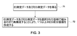
図3は、本発明の一実施形態に従って、ハイブリッド型CT検出器を使用して画像データを再構成するための模範的な論理を含む模範的な様々な処理段階の流れ図である。先ず段階71で、取得サイクル中にEI測定データ及びED測定データを得る。段階72で、EI測定データ及びED測定データを選択された態様で組み合わせて再構成することにより、1つ以上のED成分画像を作成する。一実施形態では、EI測定データ及びED測定データを組み合わせる段階は、ED測定データ及びEI測定データについて逐次近似再構成(iterative reconstruction)を行って、1つ以上のED成分画像を作成する段階を含む。逐次近似再構成法の例としては、これに限定されないが、最大尤度(ML)法、帰納的最大確率(MAP)法、加重最小自乗(WLS)法及びペナライズド(penalized) 加重最小自乗(PWLS)法が挙げられる。ED成分画像は更に処理して、線減弱係数画像、CTナンバー画像又は単一物質画像の内の少なくとも1つを作成することができる。一実施形態では、ED成分画像は、コンプトン散乱による減弱度又は光電効果による減弱度の内の少なくとも1つを表す。
FIG. 3 is a flowchart of various exemplary processing steps including exemplary logic for reconstructing image data using a hybrid CT detector, in accordance with one embodiment of the present invention. First, in step 71, EI measurement data and ED measurement data are obtained during an acquisition cycle. At
図4は、本発明の別の実施形態に従って、ハイブリッド型CT検出器を使用して画像データを再構成するための模範的な論理を含む模範的な様々な処理段階の流れ図である。段階74で、取得サイクル中にEI測定データ及びED測定データを得る。段階76で、EI測定データについて第1の再構成を行って、EI画像を得る。段階78で、ED測定データについて第2の再構成を行って、1つ以上のED成分画像を得る。段階80で、EI画像とED成分画像とを組み合わせて、更新ED成分画像又はED・EI組合せ画像を得る。当業者に理解されるように、本発明の実施形態に従ったハイブリッド型検出器の使用の結果として作成されるED画像は、完全なEDデータが得られなかったことに起因してアーティファクト又は周波数成分の欠落が生じることがある。一実施形態によれば、EI画像及びED画像はそれらのいずれかにおける情報の欠落又はアーティファクトを補償するように組み合わされる。一実施形態では、この組み合わせは、(例えば、EDデータにより視野の切断が生じた場合における)欠落したED部分を、EI画像の拡縮後のもので補修(patching)することを含む。別の実施形態では、この組み合わせは、ED画像における欠落した高周波成分を補修するための高周波成分についてEI画像を使用することを含む。更に別の実施形態では、異なるカラー・マップをオーバーレイすることによってED画像とEI画像とを組み合わせることができる。更に、特定の実施形態では、第1の再構成は、EI画像を得るためにフィルタ補正逆投影法を使用して遂行することができる。また第2の再構成は、1つ以上のED成分画像を作成するために逐次近似再構成法を使用して遂行することができる。
FIG. 4 is a flowchart of exemplary various processing steps including exemplary logic for reconstructing image data using a hybrid CT detector, in accordance with another embodiment of the present invention. In step 74, EI measurement data and ED measurement data are obtained during the acquisition cycle. In
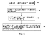
図5は、本発明の別の実施形態に従って、ハイブリッド型CT検出器を使用して画像データを再構成するための模範的な論理を含む模範的な様々な処理段階の流れ図である。先ず段階82で、取得サイクル中にEI測定データ及びED測定データを得る。段階84で、EI測定データ及びED測定データを選択的に組み合わせる。一実施形態では、このEI測定データ及びED測定データ選択的に組み合わせる段階は、(例えば、EDデータにより視野の切断が生じた場合における)欠落したED部分を、EIデータの拡縮後のもので補修することを含む。別の実施形態では、この組み合わせる段階は、EDデータにおける欠落した高周波成分を補修するための高周波成分についてEIデータを使用することを含む。段階86で、組み合わせたEI測定データ及びED測定データに基づいて、EIデータセット及び/又は1つ以上のED成分データセットを作成する。段階88で、EIデータセット及び1つ以上のED成分データセットに基づいて再構成を行って、EI再構成画像と1つ以上のED成分画像との内の少なくとも1つを作成する。更に、一実施形態では、EIデータセットについてフィルタ補正逆投影再構成を行って、EI再構成画像を作成し、またED成分データセットについて逐次近似再構成を行って、1つ以上のED成分画像を作成する。
FIG. 5 is a flow diagram of exemplary various processing steps including exemplary logic for reconstructing image data using a hybrid CT detector in accordance with another embodiment of the present invention. First, in
図6は、本発明の更に別の実施形態に従って、ハイブリッド型CT検出器を使用して画像データを再構成するための模範的な論理を含む模範的な様々な処理段階の流れ図である。先ず段階90で、取得サイクル中にEI測定データ及びED測定データを得る。段階92で、EI測定データに基づいて第1の再構成を行って、EI画像を作成する。段階94で、ED測定データ及びEI画像に基づいて第2の再構成を行って、1つ以上のED成分画像を作成する。特定の実施形態では、EI画像はED画像を再構成するための出発点として又は事前情報として使用される。事前情報は、ED画像における疎らな又は欠落したデータを補償する。更に、EI画像は、変換関数を使用して、1つ以上のED成分画像の逐次近似再構成のための最初の推定値を生じるように変換することができる。この変換されたEI画像は、逐次近似再構成処理中にED画像についての制約として、又はED画像の逐次近似再構成より以前の絶対強度として使用することができる。更に、或る特定の実施形態では、フィルタ補正逆投影再構成を使用して第1の再構成を行って、EI画像を得ることができる。また、逐次近似再構成を使用して第2の再構成を行って、1つ以上のED成分画像を作成することができる。一実施形態では、第2の再構成は、EI画像を拡縮する段階、EI画像をED成分画像の逐次近似再構成における最初の推定値として使用する段階、又はEI画像をED成分画像の逐次近似再構成における事前情報として使用する段階を含む。別の実施形態では、第2の再構成は、第1の成分を固定した状態に保ちながら、2物質空間内で第1の成分に対して直交する第2の成分を再構成する。例えば、第1の成分が水の密度を表している場合、第2の成分はゼロの水密度を持つ。
FIG. 6 is a flow diagram of exemplary various processing steps including exemplary logic for reconstructing image data using a hybrid CT detector, according to yet another embodiment of the present invention. First, in step 90, EI measurement data and ED measurement data are obtained during an acquisition cycle. In
図7は、本発明の更に別の実施形態に従って、ハイブリッド型CT検出器を使用して画像データを再構成するための模範的な論理を含む模範的な様々な処理段階の流れ図である。先ず段階96で、取得サイクル中にEI測定データ及びED測定データを得る。段階98で、EI測定データについて第1の再構成を行って、EI画像を作成する。段階100で、EI画像について区分化アルゴリズムを適用して、区分された画像を作成する。一実施形態では、区分化アルゴリズムは、EI画像を、骨領域、軟組織又はヨウ素領域の内の少なくとも1つにセグメント化する。当業者に理解されるように、区分化アルゴリズム(又はセグメント化アルゴリズム)は、二次導関数のゼロ交差のような簡単な閾値判定手法に基づいたものである。区分化アルゴリズムはまた、区分化段階で役立つ、例えばアトラスの形態の解剖学的情報を使用することができる。段階102で、ED測定データ及び区分された画像に基づいて第2の再構成を行って、1つ以上のED成分画像を作成する。一実施形態では、第2の再構成は、EI画像を拡縮する段階、EI画像をED成分画像の逐次近似再構成における最初の推定値として使用する段階、又はEI画像をED成分画像の逐次近似再構成における事前情報として使用する段階を含む。別の実施形態では、第2の再構成は、区分化アルゴリズムによって識別された通りの特定の組織分類(例えば、ヨウ素と骨)で各領域を再構成することができる。
FIG. 7 is a flowchart of exemplary various processing steps including exemplary logic for reconstructing image data using a hybrid CT detector, according to yet another embodiment of the present invention. First, in step 96, EI measurement data and ED measurement data are obtained during an acquisition cycle. In
本書では本発明の或る特定の特徴のみを例示して説明したが、当業者には多くの修正及び変更を為し得よう。従って、特許請求の範囲が本発明の真の精神に範囲内にあるこのような修正及び変更の全てをカバーするものであることを理解されたい。また、図面の符号に対応する特許請求の範囲中の符号は、単に本願発明の理解をより容易にするために用いられているものであり、本願発明の範囲を狭める意図で用いられたものではない。そして、本願の特許請求の範囲に記載した事項は、明細書に組み込まれ、明細書の記載事項の一部となる。
Although only certain specific features of the invention have been illustrated and described herein, many modifications and changes will occur to those skilled in the art. Accordingly, it is to be understood that the appended claims are intended to cover all such modifications and changes as fall within the true spirit of this invention. Further, the reference numerals in the claims corresponding to the reference numerals in the drawings are merely used for easier understanding of the present invention, and are not intended to narrow the scope of the present invention. Absent. The matters described in the claims of the present application are incorporated into the specification and become a part of the description items of the specification.
10 画像データを取得し処理するシステム
12 X線放射線源
14 コリメータ
16 放射線の流れ
18 患者
20 放射線
22 検出器アレイ
24 システム制御装置
26 線形位置決めサブシステム
28 回転サブシステム
50、55、57、58、59、60、62 ハイブリッド型検出器のセル構成
52 EI検出器セル
54 ED検出器セル
56 減衰器
63 第1の放射線源
64 第2の放射線源
65 円弧状検出器
66 第1の側方翼状部
67 第2の側方翼状部
68 中央部
69 比較的大きい関心のある領域
70 比較的小さい関心のある領域
DESCRIPTION OF
Claims (10)
取得サイクル中にEI測定データ及びED測定データを得る段階と、
選択された態様で前記EI測定データと前記ED測定データとを組み合わせる段階と
を含み、前記組み合わせる段階が、
前記EI測定データに基づいて第1の再構成を行って、EI画像を得る段階と、
前記ED測定データに基づいて第2の再構成を行って、少なくとも1つのED成分画像を得る段階と、
前記EI画像と前記少なくとも1つのED成分画像とを組み合わせて、前記EI画像または前記ED成分画像の情報の欠陥またはアーティファクトを補償した、更新ED成分画像およびED・EI組合せ画像の内うちの少なくとも1つを得る段階と、
を含む、方法。 A method for obtaining an image data set comprising energy integration (EI) and energy discrimination (ED) data measurements comprising:
Obtaining EI measurement data and ED measurement data during an acquisition cycle;
Combining the EI measurement data and the ED measurement data in a selected manner, the combining step comprising:
Performing a first reconstruction based on the EI measurement data to obtain an EI image;
Performing a second reconstruction based on the ED measurement data to obtain at least one ED component image;
At least one of the updated ED component image and the combined ED / EI image in which the EI image and the at least one ED component image are combined to compensate for information defects or artifacts in the EI image or the ED component image. To get one,
Including a method.
取得サイクル中にEI測定データ及びED測定データを得る段階と、
前記EI測定データ及び前記ED測定データを選択的に組み合わせる段階と、
前記組み合わせたEI測定データ及びED測定データに基づいてEIデータセット及び1つ以上のED成分データセットの内の少なくとも1つを作成する段階と、
前記EIデータセット及び前記1つ以上のED成分データセットに基づいて再構成を行って、前記EIデータセットまたは前記ED成分データセットの情報の欠陥またはアーティファクトを補償した、EI再構成画像及び1つ以上のED成分画像の内の少なくとも1つを作成する段階と、
を含む、方法。 A method for obtaining an image data set comprising energy integration (EI) and energy discrimination (ED) data measurements comprising:
Obtaining EI measurement data and ED measurement data during an acquisition cycle;
Selectively combining the EI measurement data and the ED measurement data;
Creating at least one of an EI data set and one or more ED component data sets based on the combined EI measurement data and ED measurement data;
An EI reconstructed image and one that is reconstructed based on the EI data set and the one or more ED component data sets to compensate for defects or artifacts in information of the EI data set or the ED component data set; Creating at least one of the above ED component images;
Including a method.
取得サイクル中にEI測定データ及びED測定データを得る段階と、
前記EI測定データに基づいて第1の再構成を行って、EI画像を作成する段階と、
前記ED測定データ及び前記EI画像に基づいて第2の再構成を行って、前記ED測定データの情報の欠陥またはアーティファクトを補償した、1つ以上のED成分画像を作成する段階と、
を含む、方法。 A method for obtaining an image data set comprising energy integration (EI) and energy discrimination (ED) data measurements comprising:
Obtaining EI measurement data and ED measurement data during an acquisition cycle;
Performing a first reconstruction based on the EI measurement data to create an EI image;
Performing a second reconstruction based on the ED measurement data and the EI image to create one or more ED component images compensated for defects or artifacts in the information of the ED measurement data;
Including a method.
取得サイクル中にEI測定データ及びED測定データを得る段階と、
前記EI測定データに基づいて第1の再構成を行って、EI画像を作成する段階と、
前記EI画像について区分化アルゴリズムを適用して、区分された画像を作成する段階と、
前記ED測定データ及び前記区分された画像に基づいて第2の再構成を行って、前記ED測定データの情報の欠陥またはアーティファクトを補償した、1つ以上のED成分画像を作成する段階と、
を含む、方法。 A method for obtaining an image data set comprising energy integration (EI) and energy discrimination (ED) data measurements comprising:
Obtaining EI measurement data and ED measurement data during an acquisition cycle;
Performing a first reconstruction based on the EI measurement data to create an EI image;
Applying a segmentation algorithm to the EI image to create a segmented image;
Performing a second reconstruction based on the ED measurement data and the segmented image to create one or more ED component images that compensate for defects or artifacts in the information of the ED measurement data;
Including a method.
The method of claim 9, wherein the segmentation algorithm includes segmenting the EI image into at least one of a bone region, a soft tissue, or an iodine region.
Applications Claiming Priority (2)
| Application Number | Priority Date | Filing Date | Title |
|---|---|---|---|
| US11/317,841 US7372934B2 (en) | 2005-12-22 | 2005-12-22 | Method for performing image reconstruction using hybrid computed tomography detectors |
| US11/317,841 | 2005-12-22 |
Publications (2)
| Publication Number | Publication Date |
|---|---|
| JP2007167663A JP2007167663A (en) | 2007-07-05 |
| JP5469293B2 true JP5469293B2 (en) | 2014-04-16 |
Family
ID=38135998
Family Applications (1)
| Application Number | Title | Priority Date | Filing Date |
|---|---|---|---|
| JP2006343734A Expired - Fee Related JP5469293B2 (en) | 2005-12-22 | 2006-12-21 | Method for image reconstruction using a hybrid computed tomography detector |
Country Status (4)
| Country | Link |
|---|---|
| US (1) | US7372934B2 (en) |
| JP (1) | JP5469293B2 (en) |
| CN (1) | CN1985765B (en) |
| DE (1) | DE102006060493A1 (en) |
Families Citing this family (57)
| Publication number | Priority date | Publication date | Assignee | Title |
|---|---|---|---|---|
| US9113839B2 (en) | 2003-04-25 | 2015-08-25 | Rapiscon Systems, Inc. | X-ray inspection system and method |
| US8837669B2 (en) | 2003-04-25 | 2014-09-16 | Rapiscan Systems, Inc. | X-ray scanning system |
| US8451974B2 (en) | 2003-04-25 | 2013-05-28 | Rapiscan Systems, Inc. | X-ray tomographic inspection system for the identification of specific target items |
| US8223919B2 (en) | 2003-04-25 | 2012-07-17 | Rapiscan Systems, Inc. | X-ray tomographic inspection systems for the identification of specific target items |
| GB0525593D0 (en) | 2005-12-16 | 2006-01-25 | Cxr Ltd | X-ray tomography inspection systems |
| US7949101B2 (en) | 2005-12-16 | 2011-05-24 | Rapiscan Systems, Inc. | X-ray scanners and X-ray sources therefor |
| US8243876B2 (en) | 2003-04-25 | 2012-08-14 | Rapiscan Systems, Inc. | X-ray scanners |
| US7983462B2 (en) * | 2005-11-22 | 2011-07-19 | Purdue Research Foundation | Methods and systems for improving quality of an image |
| US20070205367A1 (en) * | 2006-03-01 | 2007-09-06 | General Electric Company | Apparatus and method for hybrid computed tomography imaging |
| WO2008135897A2 (en) * | 2007-05-04 | 2008-11-13 | Koninklijke Philips Electronics N.V. | Detection device for detecting radiation and imaging system for imaging a region of interest |
| US7433443B1 (en) * | 2007-08-29 | 2008-10-07 | General Electric Company | System and method of CT imaging with second tube/detector patching |
| US9070181B2 (en) * | 2007-12-21 | 2015-06-30 | General Electric Company | System and method for extracting features of interest from an image |
| DE102008013413B4 (en) * | 2008-03-10 | 2010-08-19 | Siemens Aktiengesellschaft | Layered x-ray detector and method for generating an x-ray image |
| JP5179268B2 (en) * | 2008-06-17 | 2013-04-10 | ジーイー・メディカル・システムズ・グローバル・テクノロジー・カンパニー・エルエルシー | X-ray CT system |
| EP2296551B1 (en) * | 2008-06-30 | 2016-04-20 | Koninklijke Philips N.V. | Spectral ct |
| US8111803B2 (en) * | 2009-04-29 | 2012-02-07 | General Electric Company | Method for energy sensitive computed tomography using checkerboard filtering |
| US8160206B2 (en) * | 2009-12-23 | 2012-04-17 | General Electric Company | Dual-energy imaging at reduced sample rates |
| DE102010006774A1 (en) | 2010-02-04 | 2011-08-04 | Siemens Aktiengesellschaft, 80333 | CT measurement with multiple x-ray sources |
| US20110211667A1 (en) * | 2010-02-26 | 2011-09-01 | Abdelaziz Ikhlef | De-populated detector for computed tomography and method of making same |
| US8160200B2 (en) * | 2010-03-30 | 2012-04-17 | General Electric Company | Method and system for image data acquisition |
| GB2501661B (en) * | 2011-02-22 | 2017-04-12 | Rapiscan Systems Inc | X-ray inspection system and method |
| US20120236987A1 (en) * | 2011-03-18 | 2012-09-20 | David Ruimi | Multiple energy ct scanner |
| DE102011076346B4 (en) | 2011-05-24 | 2016-07-14 | Siemens Healthcare Gmbh | Method and computer tomography system for generating tomographic image data sets |
| US9119589B2 (en) * | 2012-03-22 | 2015-09-01 | Kabushiki Kaisha Toshiba | Method and system for spectral computed tomography (CT) with sparse photon counting detectors |
| US9237874B2 (en) | 2012-04-30 | 2016-01-19 | General Electric Company | Method and system for non-invasive imaging of a target region |
| US9579075B2 (en) * | 2012-10-02 | 2017-02-28 | Analogic Corporation | Detector array comprising energy integrating and photon counting cells |
| CN103913472B (en) * | 2012-12-31 | 2016-04-20 | 同方威视技术股份有限公司 | Ct imaging system and method |
| US9861324B2 (en) | 2013-04-23 | 2018-01-09 | Virginia Tech Intellectual Properties, Inc. | Hybrid detector modules and dynamic thresholding for spectral CT |
| DE102013104193A1 (en) * | 2013-04-25 | 2014-10-30 | Smiths Heimann Gmbh | CT X-ray inspection system, in particular for the inspection of objects |
| US9724056B2 (en) * | 2013-11-28 | 2017-08-08 | Toshiba Medical Systems Corporation | Method and system for spectral computed tomography (CT) with inner ring geometry |
| WO2015011587A1 (en) * | 2013-07-23 | 2015-01-29 | Koninklijke Philips N.V. | Hybrid (spectral/non-spectral) imaging detector array and corresponding processing electronics |
| US10176603B2 (en) * | 2013-08-07 | 2019-01-08 | The University Of Chicago | Sinogram (data) domain pansharpening method and system for spectral CT |
| US9437016B2 (en) * | 2013-08-07 | 2016-09-06 | Toshiba Medical Systems Corporation | Image domain pansharpening method and system for spectral CT with large pixel energy discriminating detectors |
| DE102013217528A1 (en) | 2013-09-03 | 2015-03-05 | Siemens Aktiengesellschaft | X-ray detector |
| US9662078B2 (en) | 2013-10-09 | 2017-05-30 | Koninklijke Philips N.V. | Method and device for generating an energy-resolved X-ray image with adapted energy threshold |
| US9274066B2 (en) * | 2013-10-25 | 2016-03-01 | Kabushiki Kaisha Toshiba | Method for spectral CT local tomography |
| US9226723B2 (en) * | 2014-02-25 | 2016-01-05 | Kabushiki Kaisha Toshiba | Ordered subset scheme in spectral CT |
| US9449385B2 (en) * | 2014-06-02 | 2016-09-20 | Toshiba Medical Systems Corporation | Reconstruction of computed tomography images using combined third-generation and fourth-generation projection data |
| EP3152596B1 (en) * | 2014-06-04 | 2019-07-31 | Koninklijke Philips N.V. | Imaging system for generating an image of an object |
| JP6313168B2 (en) * | 2014-09-02 | 2018-04-18 | キヤノンメディカルシステムズ株式会社 | X-ray CT apparatus, image processing apparatus, and image processing program |
| JP6479967B2 (en) * | 2014-09-19 | 2019-03-06 | コーニンクレッカ フィリップス エヌ ヴェKoninklijke Philips N.V. | Spectral projection extension |
| CN107077748B (en) * | 2014-10-20 | 2020-10-27 | 皇家飞利浦有限公司 | Start image for iterative reconstruction of spectral images |
| JP6625428B2 (en) * | 2015-02-23 | 2019-12-25 | キヤノンメディカルシステムズ株式会社 | X-ray CT apparatus and image processing apparatus |
| US10646176B2 (en) * | 2015-09-30 | 2020-05-12 | General Electric Company | Layered radiation detector |
| US10219775B2 (en) | 2015-11-02 | 2019-03-05 | Toshiba Medical Systems Corporation | Photon-counting X-ray CT apparatus and image processing apparatus |
| DE102015226489B4 (en) * | 2015-12-22 | 2024-05-16 | Siemens Healthineers Ag | X-ray system and method for image reconstruction |
| US10646186B2 (en) | 2016-01-18 | 2020-05-12 | Canon Medical Systems Corporation | X-ray CT apparatus, information processing device and information processing method |
| CN107019518B (en) * | 2016-02-01 | 2020-07-28 | 通用电气公司 | Signal processing method and imaging system for scatter correction in computed tomography |
| CN109196957B (en) * | 2016-05-31 | 2023-07-04 | 皇家飞利浦有限公司 | Device for generating X-rays |
| WO2017211625A1 (en) | 2016-06-07 | 2017-12-14 | Koninklijke Philips N.V. | Improved precision and resolution of quantitative imaging by combining spectral and non-spectral material decomposition |
| CN109310388B (en) * | 2016-09-30 | 2022-04-15 | 深圳迈瑞生物医疗电子股份有限公司 | Imaging method and system |
| JP6956626B2 (en) * | 2017-01-24 | 2021-11-02 | キヤノンメディカルシステムズ株式会社 | X-ray CT equipment and reconstruction processing equipment |
| US10585206B2 (en) | 2017-09-06 | 2020-03-10 | Rapiscan Systems, Inc. | Method and system for a multi-view scanner |
| US11212902B2 (en) | 2020-02-25 | 2021-12-28 | Rapiscan Systems, Inc. | Multiplexed drive systems and methods for a multi-emitter X-ray source |
| US11517274B2 (en) | 2020-06-02 | 2022-12-06 | Wisconsin Alumni Research Foundation | Hybrid detection systems and methods for C-arm interventional x-ray systems |
| US11593926B2 (en) * | 2021-02-09 | 2023-02-28 | Elucid Bioimaging Inc. | Systems and methods for improving soft tissue contrast, multiscale modeling and spectral CT |
| US12419596B2 (en) | 2022-07-26 | 2025-09-23 | GE Precision Healthcare LLC | Systems and methods for computed tomography |
Family Cites Families (21)
| Publication number | Priority date | Publication date | Assignee | Title |
|---|---|---|---|---|
| JPS5591338A (en) * | 1978-12-28 | 1980-07-10 | Shimadzu Corp | Xxray tomography device |
| JPS58206726A (en) * | 1982-05-28 | 1983-12-02 | 株式会社日立製作所 | Image treating apparatus |
| JPS6075036A (en) * | 1983-09-30 | 1985-04-27 | 株式会社東芝 | Multicolor x-ray ct apparatus |
| JPS6236704U (en) * | 1985-08-24 | 1987-03-04 | ||
| US5376795A (en) * | 1990-07-09 | 1994-12-27 | Regents Of The University Of California | Emission-transmission imaging system using single energy and dual energy transmission and radionuclide emission data |
| JP3449561B2 (en) * | 1993-04-19 | 2003-09-22 | 東芝医用システムエンジニアリング株式会社 | X-ray CT system |
| JPH09108207A (en) * | 1995-10-20 | 1997-04-28 | Hitachi Ltd | X-ray detection method |
| JPH09149901A (en) * | 1995-11-30 | 1997-06-10 | Toshiba Corp | Image generating apparatus and image generating method |
| US6236050B1 (en) * | 1996-02-02 | 2001-05-22 | TüMER TüMAY O. | Method and apparatus for radiation detection |
| US5742660A (en) * | 1997-01-10 | 1998-04-21 | Southeastern Universities Research Association, Inc. | Dual energy scanning beam laminographic x-radiography |
| JP2002077132A (en) * | 2000-08-29 | 2002-03-15 | Dainippon Printing Co Ltd | Information providing system, server computer, portable terminal, and recording medium |
| US6904118B2 (en) | 2002-07-23 | 2005-06-07 | General Electric Company | Method and apparatus for generating a density map using dual-energy CT |
| JP4114717B2 (en) * | 2002-08-09 | 2008-07-09 | 浜松ホトニクス株式会社 | CT equipment |
| US6819738B2 (en) | 2002-08-15 | 2004-11-16 | Ge Medical Systems Global Technology Company, Llc | Hybrid scintillator/photo sensor & direct conversion detector |
| JP2004129812A (en) * | 2002-10-10 | 2004-04-30 | Ge Medical Systems Global Technology Co Llc | Ct photographing method, ct image generation method and x-ray ct device |
| US6999549B2 (en) * | 2002-11-27 | 2006-02-14 | Ge Medical Systems Global Technology, Llc | Method and apparatus for quantifying tissue fat content |
| US7272429B2 (en) * | 2002-11-27 | 2007-09-18 | Ge Medical Systems Global Technology Company, Llc | Methods and apparatus for facilitating a reduction in artifacts |
| US6898263B2 (en) * | 2002-11-27 | 2005-05-24 | Ge Medical Systems Global Technology Company, Llc | Method and apparatus for soft-tissue volume visualization |
| US7129498B2 (en) * | 2003-09-23 | 2006-10-31 | General Electric Company | Compact structural CT detector module |
| US20070019782A1 (en) * | 2003-10-14 | 2007-01-25 | Udo Van Stevendaal | Fan-beam coherent-scatter computed tomography |
| US7105828B2 (en) * | 2004-02-10 | 2006-09-12 | Ge Medical Systems Global Technology Company, Llc | Hybrid x-ray detector |
-
2005
- 2005-12-22 US US11/317,841 patent/US7372934B2/en not_active Expired - Lifetime
-
2006
- 2006-12-19 DE DE102006060493A patent/DE102006060493A1/en not_active Withdrawn
- 2006-12-21 JP JP2006343734A patent/JP5469293B2/en not_active Expired - Fee Related
- 2006-12-22 CN CN2006101701540A patent/CN1985765B/en not_active Expired - Fee Related
Also Published As
| Publication number | Publication date |
|---|---|
| CN1985765B (en) | 2011-03-09 |
| JP2007167663A (en) | 2007-07-05 |
| DE102006060493A1 (en) | 2007-07-05 |
| US7372934B2 (en) | 2008-05-13 |
| CN1985765A (en) | 2007-06-27 |
| US20070147574A1 (en) | 2007-06-28 |
Similar Documents
| Publication | Publication Date | Title |
|---|---|---|
| JP5469293B2 (en) | Method for image reconstruction using a hybrid computed tomography detector | |
| US7760848B2 (en) | Method and system for generating a multi-spectral image of an object | |
| US6904118B2 (en) | Method and apparatus for generating a density map using dual-energy CT | |
| US8160206B2 (en) | Dual-energy imaging at reduced sample rates | |
| US9025815B2 (en) | System and method for multi-material correction of image data | |
| US8705822B2 (en) | Method for creating images indicating material decomposition in dual energy, dual source helical computed tomography | |
| CN106233335B (en) | X-ray spectrum imaging method and system | |
| US7396162B1 (en) | Scatter correction for CT method and apparatus | |
| US8396273B2 (en) | Noise reduction method for dual-energy imaging | |
| JP2008062035A5 (en) | ||
| US20090129539A1 (en) | Computed tomography method and system | |
| US11246555B2 (en) | Systems and methods for automatic tube potential selection in dual energy imaging | |
| JP2009515634A (en) | System and method for using x-ray tube spectrum in computer tomography applications | |
| US20100310036A1 (en) | Computed tomography method and apparatus | |
| US7643866B2 (en) | Method for producing a computed tomography display of tissue structures by applying a contrast medium | |
| US20160106386A1 (en) | Methods and systems for task-based data generation and weighting for ct spectral imaging | |
| US10383589B2 (en) | Direct monochromatic image generation for spectral computed tomography | |
| US20160134852A1 (en) | System and method for multi-material correction of image data | |
| US11270477B2 (en) | Systems and methods for tailored image texture in iterative image reconstruction | |
| Gonzales et al. | Rectangular computed tomography using a stationary array of CNT emitters: initial experimental results | |
| CN107212898B (en) | Image reconstruction method | |
| Cierniak | Technical concepts of X-ray computed tomography scanners |
Legal Events
| Date | Code | Title | Description |
|---|---|---|---|
| A621 | Written request for application examination |
Free format text: JAPANESE INTERMEDIATE CODE: A621 Effective date: 20091214 |
|
| RD04 | Notification of resignation of power of attorney |
Free format text: JAPANESE INTERMEDIATE CODE: A7424 Effective date: 20091214 |
|
| A521 | Request for written amendment filed |
Free format text: JAPANESE INTERMEDIATE CODE: A523 Effective date: 20101213 |
|
| A977 | Report on retrieval |
Free format text: JAPANESE INTERMEDIATE CODE: A971007 Effective date: 20120301 |
|
| A131 | Notification of reasons for refusal |
Free format text: JAPANESE INTERMEDIATE CODE: A131 Effective date: 20120313 |
|
| A521 | Request for written amendment filed |
Free format text: JAPANESE INTERMEDIATE CODE: A523 Effective date: 20120528 |
|
| A131 | Notification of reasons for refusal |
Free format text: JAPANESE INTERMEDIATE CODE: A131 Effective date: 20130108 |
|
| A521 | Request for written amendment filed |
Free format text: JAPANESE INTERMEDIATE CODE: A523 Effective date: 20130405 |
|
| TRDD | Decision of grant or rejection written | ||
| A01 | Written decision to grant a patent or to grant a registration (utility model) |
Free format text: JAPANESE INTERMEDIATE CODE: A01 Effective date: 20140108 |
|
| A61 | First payment of annual fees (during grant procedure) |
Free format text: JAPANESE INTERMEDIATE CODE: A61 Effective date: 20140131 |
|
| R150 | Certificate of patent or registration of utility model |
Ref document number: 5469293 Country of ref document: JP Free format text: JAPANESE INTERMEDIATE CODE: R150 Free format text: JAPANESE INTERMEDIATE CODE: R150 |
|
| R250 | Receipt of annual fees |
Free format text: JAPANESE INTERMEDIATE CODE: R250 |
|
| R250 | Receipt of annual fees |
Free format text: JAPANESE INTERMEDIATE CODE: R250 |
|
| R250 | Receipt of annual fees |
Free format text: JAPANESE INTERMEDIATE CODE: R250 |
|
| R250 | Receipt of annual fees |
Free format text: JAPANESE INTERMEDIATE CODE: R250 |
|
| R250 | Receipt of annual fees |
Free format text: JAPANESE INTERMEDIATE CODE: R250 |
|
| R250 | Receipt of annual fees |
Free format text: JAPANESE INTERMEDIATE CODE: R250 |
|
| R250 | Receipt of annual fees |
Free format text: JAPANESE INTERMEDIATE CODE: R250 |
|
| R250 | Receipt of annual fees |
Free format text: JAPANESE INTERMEDIATE CODE: R250 |
|
| LAPS | Cancellation because of no payment of annual fees |