JP5469253B2 - Flange device and intake system - Google Patents
Flange device and intake system Download PDFInfo
- Publication number
- JP5469253B2 JP5469253B2 JP2012540366A JP2012540366A JP5469253B2 JP 5469253 B2 JP5469253 B2 JP 5469253B2 JP 2012540366 A JP2012540366 A JP 2012540366A JP 2012540366 A JP2012540366 A JP 2012540366A JP 5469253 B2 JP5469253 B2 JP 5469253B2
- Authority
- JP
- Japan
- Prior art keywords
- flange
- housing
- intake
- internal combustion
- combustion engine
- Prior art date
- Legal status (The legal status is an assumption and is not a legal conclusion. Google has not performed a legal analysis and makes no representation as to the accuracy of the status listed.)
- Expired - Fee Related
Links
Images


Classifications
-
- F—MECHANICAL ENGINEERING; LIGHTING; HEATING; WEAPONS; BLASTING
- F02—COMBUSTION ENGINES; HOT-GAS OR COMBUSTION-PRODUCT ENGINE PLANTS
- F02M—SUPPLYING COMBUSTION ENGINES IN GENERAL WITH COMBUSTIBLE MIXTURES OR CONSTITUENTS THEREOF
- F02M35/00—Combustion-air cleaners, air intakes, intake silencers, or induction systems specially adapted for, or arranged on, internal-combustion engines
- F02M35/10—Air intakes; Induction systems
- F02M35/10006—Air intakes; Induction systems characterised by the position of elements of the air intake system in direction of the air intake flow, i.e. between ambient air inlet and supply to the combustion chamber
- F02M35/10078—Connections of intake systems to the engine
-
- F—MECHANICAL ENGINEERING; LIGHTING; HEATING; WEAPONS; BLASTING
- F02—COMBUSTION ENGINES; HOT-GAS OR COMBUSTION-PRODUCT ENGINE PLANTS
- F02M—SUPPLYING COMBUSTION ENGINES IN GENERAL WITH COMBUSTIBLE MIXTURES OR CONSTITUENTS THEREOF
- F02M55/00—Fuel-injection apparatus characterised by their fuel conduits or their venting means; Arrangements of conduits between fuel tank and pump F02M37/00
- F02M55/02—Conduits between injection pumps and injectors, e.g. conduits between pump and common-rail or conduits between common-rail and injectors
- F02M55/025—Common rails
Description
本発明は、特に自動車の内燃機関の吸気装置のフランジ装置に関する。また、本発明は、そのようなフランジ装置が設けられた吸気システムに関する。 The present invention particularly relates to a flange device for an intake device of an internal combustion engine of an automobile. The present invention also relates to an intake system provided with such a flange device.
特許文献1から内燃機関の吸気システムのフランジ装置が公知であって、このフランジ装置は、プラスチック製のハウジングと、金属製の燃料分配レールと、を備えている。このハウジングは、内燃機関の各シリンダに適した吸入管を有し、燃料分配レールは、燃料噴射器と接続するための各シリンダのコネクタを有している。さらに、公知のフランジ装置には金属製のホールドダウン装置が設けられ、これにより上記ハウジングは内燃機関に固定され、このホールドダウン装置が上記燃料分配レールの一部を覆っており、ハウジングが固定されることで燃料分配レールも同時に固定される。 Patent Document 1 discloses a flange device for an intake system of an internal combustion engine. The flange device includes a plastic housing and a metal fuel distribution rail. The housing has a suction pipe suitable for each cylinder of the internal combustion engine, and the fuel distribution rail has a connector for each cylinder for connection with a fuel injector. Further, the known flange device is provided with a metal hold-down device, whereby the housing is fixed to the internal combustion engine, the hold-down device covers a part of the fuel distribution rail, and the housing is fixed. This also fixes the fuel distribution rail at the same time.
特許文献2からさらにフランジ装置が公知であり、このフランジ装置は、プラスチック製のハウジングと、金属製の燃料分配レールと、を備えている。このフランジ装置において、橋絡部が燃料分配レール上に一体に形成され、この橋絡部は、吸入管と隣接する上記ハウジングの一部を覆っており、またこの橋絡部によって燃料分配レール及びハウジングが内燃機関に固定されている。
Further, a flange device is known from
特許文献3から吸気システムが公知であり、そのハウジングはプラスチック製であり、このハウジング上に金属製の燃料分配レールが固定されている。 An intake system is known from US Pat. No. 6,057,028, the housing of which is made of plastic, on which a metal fuel distribution rail is fixed.
さらに特許文献4からフランジ装置が公知であり、冷媒分配管を内燃機関に同時に固定するために、このフランジ装置ではプラスチック製のハウジングが内燃機関に固定され、該ハウジングが、冷媒分配管の分岐管にぴったり合うように形成されたカラー形状管の戻り止め凹部の一部を覆っている。その際、上記冷媒分配管は、内燃機関と離れて対向する上記ハウジング側の分岐管同士の間を通り、管端部と連携する上記ハウジングの各部分と重なっている。 Further, a flange device is known from Patent Document 4, and in order to fix the refrigerant distribution pipe to the internal combustion engine at the same time, in this flange apparatus, a plastic housing is fixed to the internal combustion engine, and the housing is a branch pipe of the refrigerant distribution pipe. A portion of the detent recess of the collar-shaped tube formed so as to fit closely to is covered. At that time, the refrigerant distribution pipe passes between the branch pipes on the housing side facing away from the internal combustion engine, and overlaps each portion of the housing that cooperates with the pipe end.
本発明は、導入部に記載のタイプのフランジ装置又は吸気システムに改善された実施形態、又は、少なくとも異なる実施形態を提供するという課題に関し、当該実施形態は特に有利なコスト及び/又は簡単な据付能力で区別される。 The present invention relates to the problem of providing an improved embodiment, or at least a different embodiment, for a flange device or intake system of the type described in the introduction, which embodiment has a particularly advantageous cost and / or simple installation. Distinguished by ability.
本発明によれば、この課題は、独立クレームの主題によって解決される。有利な実施形態は、従属クレームの主題である。 According to the invention, this problem is solved by the subject matter of the independent claims. Advantageous embodiments are the subject matter of the dependent claims.
本発明は、複数の橋絡部をフランジ装置のハウジングに配置、特に一体に設けて、この橋絡部が、取り付けられた状態で内燃機関と離れて対向する燃料分配レールに重なるという概念に基づくものである。取り付けられた状態で、上記燃料分配レールは上記ハウジングに固定され、上記燃料分配レール及び上記ハウジングは別々に製造された部品である。上記内燃機関の上記橋絡部の支持は、支持スリーブによって実現され、この支持スリーブの一端は上記橋絡部に配置され、他端は上記内燃機関に配置されている。上記ハウジングは、上記内燃機関のフランジを用いて上記燃料分配レールの一方側に直接固定される一方、上記内燃機関の橋絡部の領域において支持スリーブを用いて上記燃料分配レールの他方側に固定される。上記ハウジングが上記内燃機関に固定されることにより、同時に、該ハウジングに緩挿され、押し付けられ、又は、留められる上記燃料分配レールは、内燃機関に固定され、これにより、さらなる固定手段が不要になる。上記橋絡部材の上記ハウジングへの取り付けは、ここでは特に有利である。特に樹脂成形部として構成されると好ましい上記ハウジングは、比較的近い製造較差の橋絡部を含んで製造されてもよく、これにより、上記内燃機関への固定が簡単な方法で実現される。さらに、上記橋絡部がすでに上記内燃機関のハウジングに正しく配置されているため、操作が簡単になる。さらにまた、上記橋絡部がプラスチックからなり、比較的軽いため、顕著な重量低減が可能である。他の実施形態では、上記橋絡部は単独で又は非単独で上記ハウジングに接続され、そして一部品として用いられるアッセンブリとして構成されている。 The present invention is based on the concept that a plurality of bridging portions are arranged in the housing of the flange device, particularly provided integrally, and this bridging portion overlaps with a fuel distribution rail facing away from the internal combustion engine in an attached state. Is. In the mounted state, the fuel distribution rail is fixed to the housing, and the fuel distribution rail and the housing are separately manufactured parts. The support of the bridge portion of the internal combustion engine is realized by a support sleeve, and one end of the support sleeve is arranged at the bridge portion, and the other end is arranged at the internal combustion engine. The housing is fixed directly to one side of the fuel distribution rail using a flange of the internal combustion engine, and is fixed to the other side of the fuel distribution rail using a support sleeve in the region of the bridging portion of the internal combustion engine. Is done. When the housing is fixed to the internal combustion engine, at the same time, the fuel distribution rail that is loosely inserted into, pressed against, or fastened to the housing is fixed to the internal combustion engine, thereby eliminating the need for further fixing means. Become. The attachment of the bridging member to the housing is particularly advantageous here. In particular, the housing, which is preferably configured as a resin molded part, may be manufactured including a bridging part having a relatively close manufacturing range, whereby the fixing to the internal combustion engine is realized in a simple manner. Furthermore, the bridge is already correctly arranged in the housing of the internal combustion engine, so that the operation is simplified. Furthermore, since the bridge part is made of plastic and is relatively light, significant weight reduction is possible. In another embodiment, the bridge is connected to the housing alone or not alone and is configured as an assembly that is used as one piece.
有利な実施形態によると、支持スリーブは金属製でもよく、上記各橋絡部に挿入されてもよい。上記金属製支持スリーブにより、上記内燃機関に対する十分な力によって上記ハウジングを予圧縮するために、特に高い応力又は圧縮力が上記ハウジングと内燃機関との間に維持される。金属製の支持スリーブを用いることにより、引張応力又は圧縮応力が加わった状態におけるプラスチックの変形を防ぐことができる。 According to an advantageous embodiment, the support sleeve may be made of metal and may be inserted into each of the bridges. A particularly high stress or compressive force is maintained between the housing and the internal combustion engine in order to pre-compress the housing with a sufficient force on the internal combustion engine by means of the metal support sleeve. By using the metal support sleeve, it is possible to prevent the plastic from being deformed in a state where a tensile stress or a compressive stress is applied.
上記橋絡部と上記燃料分配レールとの間の動力伝達を改善するために、上記橋絡部は、燃料分配レールと対向する、該燃料分配レールと相補的な接触領域に形成されてもよく、当該接触領域に薄板状に設けられてもよい。 In order to improve power transmission between the bridge and the fuel distribution rail, the bridge may be formed in a contact region that is opposite to the fuel distribution rail and that is complementary to the fuel distribution rail. The contact area may be provided in a thin plate shape.
特に有利な実施形態によると、吸気管が上記ハウジングと一体に形成されてもよく、該吸気管は少なくとも1本の吸入管にそれぞれ連通方式で接続されている。これにより、上記フランジ装置の集積度が増加し、フランジ装置の操作及び組み込みが簡単になる。 According to a particularly advantageous embodiment, an intake pipe may be formed integrally with the housing, the intake pipe being connected in communication with at least one intake pipe. This increases the degree of integration of the flange device, and simplifies the operation and incorporation of the flange device.
更なる発展によると、支持ウェブが上記ハウジングと一体に形成されてもよく、該支持ウェブは一方で上記橋絡部に配置され、他方で上記吸気管に配置されている。これら支持ウェブによって、上記橋絡部の上記吸気管への支持が具現化され、それにより、上記フランジ装置の安定性が向上しうる。 According to a further development, a support web may be formed integrally with the housing, the support web being arranged on the one hand on the bridge and on the other hand on the intake pipe. These support webs embody the support of the bridge to the intake pipe, thereby improving the stability of the flange device.
他の有利なさらなる発展によると、さらに吸気分配器が上記ハウジングと一体に形成されてもよく、このハウジングは上記吸入管と離れて対向する側において吸気管と連通方式で接続されている。この構成は、フランジ装置の集積度を増加させ、該フランジ装置の操作性及び据付能力を向上させる。 According to another advantageous further development, a further intake distributor may be formed in one piece with the housing, which is connected in communication with the intake pipe on the side facing away from the intake pipe. This configuration increases the degree of integration of the flange device and improves the operability and installation capability of the flange device.
この更なる発展において、吸気システムは、1つの構成要素に全ての機能装置、例えばフランジ、橋絡部、吸気分配器、吸気管、及び吸入管を有するように形成されている。上記燃料分配レールは、上記吸気システムに緩挿され、押し付けられ、又は、留められ、内燃機関に組み込まれ、吸気システムと一体になっている。 In this further development, the intake system is formed with all functional devices such as flanges, bridges, intake distributors, intake pipes, and intake pipes in one component. The fuel distribution rail is loosely inserted, pressed, or fastened into the intake system, and is incorporated into the internal combustion engine, and is integrated with the intake system.
他の実施形態では、少なくとも1つの上記フランジ、橋絡部、及び上記吸入管を備えるフランジ装置は、単独のユニットとして具体化され、そして、結合されている。特に、少なくとも1つの吸気分配器及び吸入管を備えるインテークマニホールドが設けられた完璧な吸気システムを形成するためにネジで固定されている。 In another embodiment, the flange device comprising at least one of the flange, the bridging portion, and the suction pipe is embodied and coupled as a single unit. In particular, it is screwed on to form a complete intake system provided with an intake manifold with at least one intake distributor and intake pipe.
その他の実施形態では、このような吸気ユニットは、例えば冷却器を有する若しくは有しないコンプレッサ又はディストリビュータでもよい。 In other embodiments, such an intake unit may be, for example, a compressor or distributor with or without a cooler.
本発明のさらに重要な特徴及び利点は、従属クレーム、図面及び図面を用いた関連のある形状の説明から明らかとなる。 Further important features and advantages of the invention emerge from the dependent claims, the drawings and the description of the relevant shapes using the drawings.
上記特徴及び以下で説明される特徴は、それぞれ示された組合せだけでなく、本発明の範囲を逸脱しない範囲で、他の組合せ又は単独で用いられることは言うまでもない。 It goes without saying that the above-described features and the features described below are used not only in the combinations shown, but also in other combinations or singly without departing from the scope of the present invention.
本発明の好ましい例示は、図示され、以下の記載で詳細に説明されており、同一の符号は、同一の構成、類似の構成、又は機能的に同一の構成を参照している。 Preferred embodiments of the invention are illustrated and described in detail in the following description, wherein like reference numerals refer to identical, similar, or functionally identical configurations.
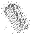
図1に示すように、部分的に図示されている吸気装置1(好ましくは吸気システム)は内燃機関に吸気するためのものであって、特に自動車に配置され、少なくとも1基のフランジ装置2と、このフランジ装置の吸気口に接続された吸気管3とを備えている。フランジ装置2は図示しない内燃機関に接続される。この内燃機関は、複数のシリンダを有するピストンエンジンである。フランジ装置2は、内燃機関の全てのシリンダに吸気を供給する役割を果たす。内燃機関がV型エンジンである場合には、フランジ装置2は、内燃機関のシリンダバンクの全てのシリンダに吸気を供給する役割を果たす。同様に、水平対向エンジン及びW型エンジンのような他のエンジンタイプにも適用される。
As shown in FIG. 1, a partially illustrated intake device 1 (preferably an intake system) is for intake into an internal combustion engine, and is particularly arranged in an automobile and includes at least one
図1〜5に示すように、フランジ装置2はハウジング4及び燃料分配レール5を備えている。ハウジング4はプラスチック製であり、特に射出成形されたものである。ハウジング4は内燃機関のシリンダ1基につき少なくとも1本の吸入管6を備えている。例えば、一般性の喪失が無ければ、正確には4本の吸入管6が設けられ、内燃機関の4基のシリンダに繋がっている。関連する内燃機関は、直列4気筒エンジン、V型8気筒エンジン、又は、8気筒エンジンと略されているエンジンである。
As shown in FIGS. 1 to 5, the
燃料分配レール5は、金属製であって、各シリンダに対してここでは図示しない燃料噴射器に接続するコネクタ7を備えている。燃料噴射器は、各シリンダに燃料を噴射する。これら燃料噴射器は、コネクタ7を介して同一の燃料分配レール5に共に接続されており、これが所謂「コモンレールシステム」である。燃料分配レール5は、ここでは円形の断面で特徴づけられた配管で構成されている。他の断面形状(例えば矩形断面)も考えられる。
The
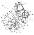
上記ハウジング4は片側にフランジ8を備え、上記内燃機関と対向する状態で組み込まれている。このフランジ8は、吸入管6又は各吸気口を囲んでいる。上記ハウジング4は、このフランジ8を用いて内燃機関に固定される。さらに、複数の橋絡部9は、ハウジング4と一体に形成されている。便宜上、このような橋絡部9はシリンダ毎に、又は、吸入管6毎に設けられている。したがって、橋絡部9は、複数の吸入管6のうちの1本の頂部に各々配置されている。上記フランジ8と離れて対向する側には、上記橋絡部9が、上記ハウジング4に緩挿され、又は、各々押し付けられた燃料分配レール5を一部覆っている。さらに、上記橋絡部9には、上記ハウジング4の長手方向において各々支持スリーブ10が設けられている。各支持スリーブ10は、ここでは各橋絡部9の吸入管6から遠位に配置され、燃料分配レール5は、支持スリーブ10と吸入管6との間に据えられている。これら支持スリーブ10を通して各橋絡部9が内燃機関に固定される。
The housing 4 has a
基本的に、上記支持スリーブ10はプラスチック製である。本実施形態では、それらは上記橋絡部9と一体に形成され、上記ハウジング4に組み込まれている。しかしながら、上記支持スリーブ10は分割して製造されるのが好ましく、それにより、当該支持スリーブ10を金属で製造し、上記ハウジング4に搭載することができる。このため、上記支持スリーブ10は、各橋絡部9に挿入されている。図5に示すように、各支持スリーブ10に対応する各橋絡部9は、対応する挿入口11を備え、この挿入口11に支持スリーブ10が挿入される。上記ハウジング4の内燃機関へのネジ締結を上記橋絡部9の領域で適切に実行すると、ネジの軸部が上記支持スリーブ10と同軸に挿通する一方、ネジの頭部が特にワッシャを介して内燃機関と離れて対向する上記支持スリーブ10の軸上正面に対向し、その際に径方向に張り出し、それにより、環状シート12上に支持され、この環状シート12が内燃機関と離れて対向する側の挿入口11に囲まれる。このようにして、全体の締結力が上記支持スリーブ10に受けとめられ、上記ハウジング4はネジ締結による応力を受けない。
Basically, the
上記支持スリーブ10は、ここでは圧力嵌め又は摩擦嵌めによって上記挿入口11に保持されてもよい。同様に、上記支持スリーブ10を上記ハウジング4に溶接することも可能である。
Here, the
上記ハウジング4を、上記内燃機関の、上記支持スリーブ10と離れて対向する上記燃料分配レール5側にネジ締結するために、ハウジング4は、図4に示すように、複数の貫通孔13を有し、ネジ締結力を受けるために、この貫通孔13にスリーブ14が適切に挿入されている。特に、これらスリーブ14は溶接されてもよい。同様に、上記ハウジング4を内燃機関に固定するために、ネジ頭部又はワッシャは内燃機関と離れて対向する上記各スリーブ14の軸上正面において径方向に重なってもよい。
In order to screw-fasten the housing 4 to the
図5に示すように、橋絡部9は、燃料分配レール5と対向し、該燃料分配レール5と相補的な接触領域15に形成されてもよく、この橋絡部9は、各橋絡部9と対向するこの接触領域15に薄板状に置かれている。これにより、特に大きな動力伝達が保証されうる。例えば、上記燃料分配レール5は環状断面を有している。これに合わせるように、上記接触領域15は半円形状で構成されている。
As shown in FIG. 5, the bridging
ここで示された実施形態において、さらに複数の吸入管16が上記ハウジング4と一体的に形成されている。これら吸入管16は、図5に示すように、少なくとも1本の吸入管6と連通している。例えば、正確には4本の吸入管16が設けられ、4本の吸入管6のうち1本に連通方式で接続されている。この実施形態において、上記ハウジング4は1シリンダ当たり2本の吸入管を有し、1本の吸入管16を同じシリンダに繋がっている2本の吸入管と接続している。
In the embodiment shown here, a plurality of
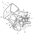
例えば、上記ハウジング4にさらに吸気分配器17が一体に形成され、該分配器は上記吸入管16に連通方式で接続されている。この吸気分配器17は、ここでは吸入管6と離れて対向する側の上記吸入管16に配置されている。
For example, an
ここで示す実施形態では、支持ウェブ18がさらに設けられ、この支持ウェブ18は、同様に、上記ハウジング4と一体に設けられてもよい。これら支持ウェブ18は、上記橋絡部9を上記吸入管16に、すなわち上記燃料分配レール5と離れて対向する側に支持する。このため、上記支持ウェブ18は、少なくとも上記燃料分配レール5と重なり合っている場合に、上記橋絡部9に沿って延びている。一方、支持ウェブ18は、各吸入管16の端部領域19まで該各吸入管16に沿って延びており、該吸入管16は関連する吸入管6に末端に配置されている。さらに、上記支持ウェブ18は、1つの橋絡部9に対して2つ構成され、各橋絡部9の該一対の支持ウェブ18は、図4に示すように、各支持スリーブ10の両側に配置されている。
In the embodiment shown here, a
ここに示された実施形態では、吸気分配器17は上記フランジ装置2の長手方向20に平行に延びている。この長手方向20は、ここでは吸入管6同士が互いに隣接して配置されるように規定されている。同時に、この長手方向20は、上記フランジ8及びハウジング4の長手方向も形成する。したがって、ここで示された実施形態では、吸気分配器17がフランジ8に平行に延びている。縦軸20に関しては、ここで示された実施形態では、吸気分配器17が正面において接続フランジ21を備え、この接続フランジ21を介して吸気システム1の吸気管3がフランジ装置1又は吸気分配器17に接続されてもよい。
In the embodiment shown here, the
図5に示すように、弁装置22は上記ハウジング4に設けられてもよく、該弁装置22は、複数の弁23を有し、これら弁23を用いて各吸入管6又は全ての吸入管6が流通可能な断面に沿って制御されうる。1シリンダ当たり1本の吸入管6が設けられている場合、上記弁装置22は吸入管6当たり1つのこのような弁23を適正に有している。1シリンダ当たり2本の吸入管6が設けられている場合、上記弁装置22は吸入管6当たり1つのこのような弁23を有している。
As shown in FIG. 5, the
特に図4に示すように、上記フランジ8と離れて対向すると共に図4の観察者と対向するように、上記ハウジング4は、複数の補強ウェブ24を有し、該補強ウェブ24は上記橋絡部9の領域に上記ハウジング4の実質的な補強に繋がる。図に示すように、ここでは補強ウェブ24が構成され、各々一対の橋絡部9の円柱節点25間の中央に形成され、ここから複数の補強ウェブ24が星形をなしている。各補強ウェブ24aはここでは上記ハウジング4の長手方向20に平行に延びており、それにより、各節点25にそれぞれ直線状に接続している。他の補強ウェブ24bは、外部の橋絡部9の端部に沿って延びている。さらに、他の補強ウェブ24cは、橋絡部9の領域と接続し、この領域に上記支持スリーブ10が配置され、ハウジング4内に上記スリーブ14が配置されている。
In particular, as shown in FIG. 4, the housing 4 has a plurality of reinforcing
上記弁装置22を駆動するために、調節駆動部26が上記ハウジング4の外部と対向するように設けられてもよく、該駆動部は、例えば圧力セルによって構成されてもよい。上記調節駆動部26は、レバー部27と駆動連結されてもよく、同様に、駆動シャフトに連結されてもよく、ここでは図示されていないが、上記調節駆動部26の駆動は、上記レバー部27を旋回させ、それにより、そこに配置されている上記弁23によって駆動シャフトを回転させる。
In order to drive the
Claims (12)
上記内燃機関の各シリンダ用の少なくとも1本の吸入管(6)を有するプラスチック製のハウジング(4)と、
燃料噴射器と接続するための上記各シリンダ用のコネクタを有する金属製の燃料分配レール(5)と、を備え、
上記ハウジング(4)は、上記吸入管(6)の吐出口を囲み且つ該ハウジング(4)が上記内燃機関に固定されるのに用いられるフランジ(8)と、該フランジ(8)と離れて対向する側の燃料分配レール(5)の一部を覆う複数の橋絡部(9)と、を有し、
上記橋絡部(9)は、上記吸入管(6)から遠位の支持スリーブ(10)を有し、
上記各橋絡部(9)は、挿入口(11)を備え、
該挿入口(11)に上記支持スリーブ(10)が挿入される一方、環状シート(12)が上記内燃機関と離れて対向する側の上記挿入口(11)に囲まれており、
上記ハウジング(4)は、ネジの軸部が上記支持スリーブ(10)と同軸に挿通されて上記内燃機関に締結される一方、ネジの頭部が、上記内燃機関と対向する上記支持スリーブ(10)の軸上正面に対向し、かつ径方向に張り出して上記ネジが上記環状シート(12)上に支持されることにより、上記内燃機関に固定されることを特徴とするフランジ装置。 A flange apparatus for an intake system for an internal combustion engine vehicles (1),
A plastic housing (4) having at least one suction pipe (6) for each cylinder of the internal combustion engine;
A metal fuel distribution rail (5) having a connector for each cylinder for connecting to a fuel injector, and
The housing (4) surrounds the discharge port of the suction pipe (6) and is separated from the flange (8) and the flange (8) used to fix the housing (4) to the internal combustion engine. A plurality of bridges (9) covering a part of the fuel distribution rail (5) on the opposite side,
The bridge (9) has a support sleeve (10) distal from the suction tube (6),
Each bridge (9) is provided with an insertion port (11),
The support sleeve (10) is inserted into the insertion port (11), while the annular sheet (12) is surrounded by the insertion port (11) on the side facing away from the internal combustion engine,
In the housing (4), the shaft portion of the screw is inserted coaxially with the support sleeve (10) and fastened to the internal combustion engine, while the head of the screw faces the internal combustion engine (10). The flange device is fixed to the internal combustion engine by facing the front surface of the shaft and projecting in the radial direction and being supported on the annular seat (12) .
上記支持スリーブ(10)は、金属製であって、上記各橋絡部(9)に挿入されていることを特徴とするフランジ装置。 The flange device according to claim 1,
The flange device, wherein the support sleeve (10) is made of metal and is inserted into each of the bridging portions (9).
上記橋絡部(9)は、該燃料分配レール(5)と対向する接触領域(15)において該燃料分配レール(5)と相補的に形成され、該接触領域(15)に薄板状で置かれていることを特徴とするフランジ装置。 In the flange apparatus according to claim 1 or 2,
The bridging portion (9) is formed complementary to the fuel distribution rail (5) in a contact region (15) facing the fuel distribution rail (5), and is placed in a thin plate shape in the contact region (15). The flange apparatus characterized by being equipped.
吸気管(16)が上記ハウジング(4)と一体に形成され、
上記吸気管(16)は、それぞれ上記吸入管(6)の少なくとも1つに連通方式で接続されていることを特徴とするフランジ装置。 In the flange apparatus of any one of Claims 1 thru | or 3,
An intake pipe (16) is formed integrally with the housing (4),
The flange device, wherein each of the intake pipes (16) is connected to at least one of the intake pipes (6) in a communicating manner.
支持ウェブ(18)が上記ハウジング(4)と一体に形成され、
上記支持ウェブ(18)は、上記燃料分配レール(5)と離れて対向する側で上記吸気管(16)上の上記橋絡部(9)を支持することを特徴とするフランジ装置。 The flange apparatus according to claim 4, wherein
A support web (18) is formed integrally with the housing (4);
The flange device, wherein the support web (18) supports the bridging portion (9) on the intake pipe (16) on a side facing away from the fuel distribution rail (5).
吸気分配器(17)が上記ハウジング(4)と一体に形成され、
上記吸気分配器(17)は、上記吸入管(6)と離れて対向する側で上記吸気管(16)と連通方式で接続することを特徴とするフランジ装置。 In the flange apparatus according to claim 4 or 5,
An intake distributor (17) is formed integrally with the housing (4),
The intake distributor (17), the flange and wherein the connecting the air intake pipe on the side facing away with the suction pipe (6) and (16) in communication method.
上記吸気分配器(17)は、上記フランジ(8)に平行に延び、正面において、上記吸気装置(1)の吸気管(3)と接続可能な接続フランジ(21)を有していることを特徴とするフランジ装置。 The flange device according to claim 6, wherein
The intake distributor (17), extending parallel to said flange (8), the positive surface, it has an intake pipe of the intake device (1) to (3) and connectable connection flange (21) A flange device characterized by.
上記ハウジング(4)内に弁装置(22)が設けられ、
上記弁装置(22)は、上記吸入管(6)の一部又は全ての弁(23)を有することを特徴とするフランジ装置。 In the flange apparatus of any one of Claims 1 thru | or 7,
A valve device (22) is provided in the housing (4),
The flange device characterized in that the valve device (22) has a part or all of the valve (23) of the suction pipe (6).
上記ハウジング(4)は、上記フランジ(8)と離れて対向する側で、上記橋絡部(9)を補強する補強ウェブ(24)を有することを特徴とするフランジ装置。 The flange device according to any one of claims 1 to 8,
The flange device according to claim 1, wherein the housing (4) has a reinforcing web (24) for reinforcing the bridging portion (9) on a side facing away from the flange (8).
上記橋絡部(9)は、上記ハウジング(4)の残部に取外し可能に又は取外し不能に取り付けられ、又は、該ハウジング(4)と一体に形成されていることを特徴とするフランジ装置。 The flange device according to any one of claims 1 to 9,
The flange device, wherein the bridging portion (9) is detachably or non-removably attached to the remaining portion of the housing (4), or is formed integrally with the housing (4).
上記燃料分配レール(5)は、上記ハウジング(4)に取り付けられ、該ハウジング(4)内に又はその上に、緩挿され、押し付けられ、又は、留められることを特徴とするフランジ装置。 The flange device according to any one of claims 1 to 10,
The flange device , wherein the fuel distribution rail (5) is attached to the housing (4) and is loosely inserted, pressed, or fastened in or on the housing (4).
請求項1乃至11のいずれか1項に記載のフランジ装置を少なくとも1つ備えることを特徴とする吸気装置。 A suction device for suction supply to an internal combustion engine of vehicles,
An air intake apparatus comprising at least one flange apparatus according to any one of claims 1 to 11.
Applications Claiming Priority (3)
| Application Number | Priority Date | Filing Date | Title |
|---|---|---|---|
| DE102009053986.7 | 2009-11-23 | ||
| DE102009053986A DE102009053986A1 (en) | 2009-11-23 | 2009-11-23 | Flange device and Saugnalage |
| PCT/EP2010/067737 WO2011061250A1 (en) | 2009-11-23 | 2010-11-18 | Flange device and intake system |
Publications (2)
| Publication Number | Publication Date |
|---|---|
| JP2013511664A JP2013511664A (en) | 2013-04-04 |
| JP5469253B2 true JP5469253B2 (en) | 2014-04-16 |
Family
ID=43513623
Family Applications (1)
| Application Number | Title | Priority Date | Filing Date |
|---|---|---|---|
| JP2012540366A Expired - Fee Related JP5469253B2 (en) | 2009-11-23 | 2010-11-18 | Flange device and intake system |
Country Status (7)
| Country | Link |
|---|---|
| US (1) | US8631784B2 (en) |
| EP (1) | EP2504558B1 (en) |
| JP (1) | JP5469253B2 (en) |
| KR (1) | KR20120085937A (en) |
| CN (1) | CN102713230B (en) |
| DE (1) | DE102009053986A1 (en) |
| WO (1) | WO2011061250A1 (en) |
Families Citing this family (7)
| Publication number | Priority date | Publication date | Assignee | Title |
|---|---|---|---|---|
| FR2950396B1 (en) * | 2009-09-22 | 2012-04-27 | Mark Iv Systemes Moteurs Sa | FUNCTIONAL MODULE INTEGRATING A DISTRIBUTOR AND INJECTION RAMP AND METHOD FOR MANUFACTURING THE SAME |
| US9273653B2 (en) * | 2014-03-03 | 2016-03-01 | MNC Flow, LLC | Intake manifold |
| DE202014104466U1 (en) | 2014-09-19 | 2014-09-25 | Benteler Automobiltechnik Gmbh | Fuel distributor |
| JP6396267B2 (en) * | 2015-08-25 | 2018-09-26 | 株式会社マーレ フィルターシステムズ | Intake device for internal combustion engine |
| DE202015105989U1 (en) * | 2015-11-09 | 2015-12-02 | Benteler Automobiltechnik Gmbh | Fuel distributor |
| DE102016204025B4 (en) * | 2016-03-11 | 2021-05-27 | Hirschvogel Umformtechnik Gmbh | Internal pressure loaded component (rail) as well as process for its production |
| FR3078104B1 (en) * | 2018-02-22 | 2021-07-23 | Sogefi Air & Cooling | MOUNTING BRACKET AND ENGINE ASSEMBLY INCLUDING IT |
Family Cites Families (20)
| Publication number | Priority date | Publication date | Assignee | Title |
|---|---|---|---|---|
| US5002030A (en) * | 1988-09-29 | 1991-03-26 | Siemens-Bendix Automotive Electronics L.P. | Fuel rail assemblies for internal combustion engines |
| DE3915111A1 (en) * | 1989-05-09 | 1990-11-15 | Bosch Gmbh Robert | FUEL DISTRIBUTOR FOR FUEL INJECTION SYSTEMS OF INTERNAL COMBUSTION ENGINES |
| US5003933A (en) * | 1989-11-06 | 1991-04-02 | General Motors Corporation | Integrated induction system |
| FR2697293B1 (en) * | 1992-10-26 | 1994-11-10 | Solex | Feeding device with integrated tubing. |
| US5713323A (en) | 1996-10-04 | 1998-02-03 | Ford Motor Company | Integrated air/fuel induction system for an internal combustion engine |
| US6408827B1 (en) * | 1999-11-12 | 2002-06-25 | Siemens Automotive Corporation | Stamped fuel rail with integrated mounting brackets |
| DE19962987A1 (en) * | 1999-12-24 | 2001-07-05 | Mahle Filtersysteme Gmbh | Piston engine |
| US6513499B2 (en) * | 2000-04-13 | 2003-02-04 | Siemens Vdo Automotive Inc. | Snap fuel rail |
| DE10131110A1 (en) | 2001-06-27 | 2003-01-09 | Mann & Hummel Filter | Intermediate flange system for a direct injection internal combustion engine |
| US6601564B2 (en) * | 2001-09-26 | 2003-08-05 | Senior Investments Ag | Flexible fuel rail |
| DE10251406B4 (en) | 2002-11-05 | 2013-08-22 | Mann + Hummel Gmbh | Suction module for an internal combustion engine |
| US20050045155A1 (en) * | 2003-08-28 | 2005-03-03 | Harvey Bruce J. | Intake manifold with injectors and captive fuel rail |
| DE10354687A1 (en) * | 2003-11-22 | 2005-06-16 | Mann + Hummel Gmbh | Suction device for an internal combustion engine |
| US6817337B1 (en) * | 2004-01-21 | 2004-11-16 | Daimlerchrysler Corporation | Cover connector |
| ITBO20040114A1 (en) * | 2004-02-27 | 2004-05-27 | Magneti Marelli Powertrain Spa | BI-MATERIAL FUEL MANIFOLD FOR AN INTERNAL COMBUSTION ENGINE WITH DIRECT FUEL INJECTION AND METHOD FOR ITS REALIZATION |
| EP1632675A1 (en) * | 2004-09-03 | 2006-03-08 | Visteon Global Technologies, Inc. | Crash protection barrier for a fuel rail system of an internal combustion engine |
| EP1760304A1 (en) * | 2005-09-02 | 2007-03-07 | Magneti Marelli Powertrain S.p.A. | Integrated air-fuel manifold for an internal combustion engine, and relative production method |
| US7591246B2 (en) * | 2006-01-17 | 2009-09-22 | Gm Global Technology Operations, Inc. | Isolated fuel delivery system |
| GB0803908D0 (en) * | 2008-03-03 | 2008-04-09 | Delphi Tech Inc | Fuel delivery system |
| EP2148076A1 (en) * | 2008-07-24 | 2010-01-27 | Magneti Marelli Powertrain S.p.A. | Integrated suction manifold provided with a fuel common rail |
-
2009
- 2009-11-23 DE DE102009053986A patent/DE102009053986A1/en not_active Withdrawn
-
2010
- 2010-11-18 KR KR1020127016518A patent/KR20120085937A/en not_active Application Discontinuation
- 2010-11-18 JP JP2012540366A patent/JP5469253B2/en not_active Expired - Fee Related
- 2010-11-18 CN CN201080053234.2A patent/CN102713230B/en not_active Expired - Fee Related
- 2010-11-18 US US13/511,328 patent/US8631784B2/en not_active Expired - Fee Related
- 2010-11-18 WO PCT/EP2010/067737 patent/WO2011061250A1/en active Application Filing
- 2010-11-18 EP EP10779807.6A patent/EP2504558B1/en not_active Not-in-force
Also Published As
| Publication number | Publication date |
|---|---|
| JP2013511664A (en) | 2013-04-04 |
| DE102009053986A1 (en) | 2011-05-26 |
| US20120298064A1 (en) | 2012-11-29 |
| CN102713230A (en) | 2012-10-03 |
| EP2504558B1 (en) | 2013-10-16 |
| EP2504558A1 (en) | 2012-10-03 |
| KR20120085937A (en) | 2012-08-01 |
| WO2011061250A1 (en) | 2011-05-26 |
| CN102713230B (en) | 2015-06-03 |
| US8631784B2 (en) | 2014-01-21 |
Similar Documents
| Publication | Publication Date | Title |
|---|---|---|
| JP5469253B2 (en) | Flange device and intake system | |
| KR100890577B1 (en) | Dual-system fuel injection engine | |
| JP4840391B2 (en) | Fuel pressure sensor mounting structure and fuel pressure detection system | |
| US7802558B2 (en) | Fuel delivery system | |
| JP5484243B2 (en) | V-type engine fuel supply system | |
| US9127630B2 (en) | Fuel supply apparatus for engine | |
| CN104254684B (en) | Device with fuel distributor and multiple Fuelinjection nozzles | |
| JP5352567B2 (en) | Fuel injection device | |
| US8459239B2 (en) | Intake device for multicylinder engine | |
| JP2010116794A (en) | Intake system for internal combustion engine | |
| JP5576352B2 (en) | Internal combustion engine | |
| US6752113B2 (en) | Mounting arrangement for an intake manifold and a method of making same | |
| JP4751366B2 (en) | Twin barrel type double throttle body in an internal combustion engine for motorcycles | |
| KR101861002B1 (en) | Fuel rail assembly for vehicle | |
| RU2415283C1 (en) | Internal combustion engine | |
| JP2007177711A (en) | Fuel injection system and fuel injection valve device applied to fuel injection system | |
| JP2009209803A (en) | Fuel supply device of multicylinder internal combustion engine | |
| JP2011047374A (en) | Fuel distributing and supplying structure of direct injection engine | |
| JP2011144693A (en) | Fixing structure for intake manifold | |
| JP2008057345A (en) | Intake device | |
| JP6182905B2 (en) | Fuel rail | |
| JPH09256928A (en) | Intake device for cylinder direct injection type gasoline engine | |
| JP2006329034A (en) | Fuel supply device of v-type internal combustion engine | |
| JP2023001806A (en) | fuel injection system | |
| KR20050096355A (en) | Fuel supply pipe laying structure for an engine |
Legal Events
| Date | Code | Title | Description |
|---|---|---|---|
| A621 | Written request for application examination |
Free format text: JAPANESE INTERMEDIATE CODE: A621 Effective date: 20130909 |
|
| A871 | Explanation of circumstances concerning accelerated examination |
Free format text: JAPANESE INTERMEDIATE CODE: A871 Effective date: 20130909 |
|
| A975 | Report on accelerated examination |
Free format text: JAPANESE INTERMEDIATE CODE: A971005 Effective date: 20131007 |
|
| A131 | Notification of reasons for refusal |
Free format text: JAPANESE INTERMEDIATE CODE: A131 Effective date: 20131022 |
|
| A521 | Request for written amendment filed |
Free format text: JAPANESE INTERMEDIATE CODE: A523 Effective date: 20131210 |
|
| TRDD | Decision of grant or rejection written | ||
| A01 | Written decision to grant a patent or to grant a registration (utility model) |
Free format text: JAPANESE INTERMEDIATE CODE: A01 Effective date: 20140114 |
|
| A61 | First payment of annual fees (during grant procedure) |
Free format text: JAPANESE INTERMEDIATE CODE: A61 Effective date: 20140130 |
|
| R150 | Certificate of patent or registration of utility model |
Ref document number: 5469253 Country of ref document: JP Free format text: JAPANESE INTERMEDIATE CODE: R150 Free format text: JAPANESE INTERMEDIATE CODE: R150 |
|
| R250 | Receipt of annual fees |
Free format text: JAPANESE INTERMEDIATE CODE: R250 |
|
| R250 | Receipt of annual fees |
Free format text: JAPANESE INTERMEDIATE CODE: R250 |
|
| R250 | Receipt of annual fees |
Free format text: JAPANESE INTERMEDIATE CODE: R250 |
|
| LAPS | Cancellation because of no payment of annual fees |