JP5467822B2 - Liquid mixing container - Google Patents
Liquid mixing container Download PDFInfo
- Publication number
- JP5467822B2 JP5467822B2 JP2009206226A JP2009206226A JP5467822B2 JP 5467822 B2 JP5467822 B2 JP 5467822B2 JP 2009206226 A JP2009206226 A JP 2009206226A JP 2009206226 A JP2009206226 A JP 2009206226A JP 5467822 B2 JP5467822 B2 JP 5467822B2
- Authority
- JP
- Japan
- Prior art keywords
- liquid
- opening
- container
- chamber
- mixing
- Prior art date
- Legal status (The legal status is an assumption and is not a legal conclusion. Google has not performed a legal analysis and makes no representation as to the accuracy of the status listed.)
- Active
Links
Images


Classifications
-
- A—HUMAN NECESSITIES
- A61—MEDICAL OR VETERINARY SCIENCE; HYGIENE
- A61C—DENTISTRY; APPARATUS OR METHODS FOR ORAL OR DENTAL HYGIENE
- A61C5/00—Filling or capping teeth
- A61C5/60—Devices specially adapted for pressing or mixing capping or filling materials, e.g. amalgam presses
-
- A—HUMAN NECESSITIES
- A61—MEDICAL OR VETERINARY SCIENCE; HYGIENE
- A61C—DENTISTRY; APPARATUS OR METHODS FOR ORAL OR DENTAL HYGIENE
- A61C5/00—Filling or capping teeth
- A61C5/60—Devices specially adapted for pressing or mixing capping or filling materials, e.g. amalgam presses
- A61C5/68—Mixing dental material components for immediate application to a site to be restored, e.g. a tooth cavity
-
- B—PERFORMING OPERATIONS; TRANSPORTING
- B01—PHYSICAL OR CHEMICAL PROCESSES OR APPARATUS IN GENERAL
- B01F—MIXING, e.g. DISSOLVING, EMULSIFYING OR DISPERSING
- B01F33/00—Other mixers; Mixing plants; Combinations of mixers
- B01F33/50—Movable or transportable mixing devices or plants
- B01F33/501—Movable mixing devices, i.e. readily shifted or displaced from one place to another, e.g. portable during use
- B01F33/5014—Movable mixing devices, i.e. readily shifted or displaced from one place to another, e.g. portable during use movable by human force, e.g. kitchen or table devices
-
- B—PERFORMING OPERATIONS; TRANSPORTING
- B01—PHYSICAL OR CHEMICAL PROCESSES OR APPARATUS IN GENERAL
- B01F—MIXING, e.g. DISSOLVING, EMULSIFYING OR DISPERSING
- B01F35/00—Accessories for mixers; Auxiliary operations or auxiliary devices; Parts or details of general application
- B01F35/71—Feed mechanisms
- B01F35/713—Feed mechanisms comprising breaking packages or parts thereof, e.g. piercing or opening sealing elements between compartments or cartridges
- B01F35/7139—Removing separation walls, plugs which close off the different compartments, e.g. by rotation or axially sliding
-
- B—PERFORMING OPERATIONS; TRANSPORTING
- B01—PHYSICAL OR CHEMICAL PROCESSES OR APPARATUS IN GENERAL
- B01F—MIXING, e.g. DISSOLVING, EMULSIFYING OR DISPERSING
- B01F35/00—Accessories for mixers; Auxiliary operations or auxiliary devices; Parts or details of general application
- B01F35/71—Feed mechanisms
- B01F35/716—Feed mechanisms characterised by the relative arrangement of the containers for feeding or mixing the components
- B01F35/7164—Feed mechanisms characterised by the relative arrangement of the containers for feeding or mixing the components the containers being placed in parallel before contacting the contents
-
- A—HUMAN NECESSITIES
- A61—MEDICAL OR VETERINARY SCIENCE; HYGIENE
- A61C—DENTISTRY; APPARATUS OR METHODS FOR ORAL OR DENTAL HYGIENE
- A61C3/00—Dental tools or instruments
- A61C3/005—Brushes for applying dental compositions
Landscapes
- Health & Medical Sciences (AREA)
- Chemical & Material Sciences (AREA)
- Chemical Kinetics & Catalysis (AREA)
- Oral & Maxillofacial Surgery (AREA)
- Dentistry (AREA)
- Epidemiology (AREA)
- Life Sciences & Earth Sciences (AREA)
- Animal Behavior & Ethology (AREA)
- General Health & Medical Sciences (AREA)
- Public Health (AREA)
- Veterinary Medicine (AREA)
- Package Specialized In Special Use (AREA)
Description
本発明は、使用時に2種以上の液を混合できる液混合容器に関する。 The present invention relates to a liquid mixing container capable of mixing two or more liquids when used.
例えば、歯科用に用いられる接着材については、複数回を繰り返して使用する容器に収容されるものと、1回分のだけの治療に用いられる容器に収容されるものがある。前者の複数回を繰り返して使用する容器は、治療回数の相当分が容器に収容され、使用時に蓋部材を開栓しその都度、必要量だけ取り出して治療を行っている。後者の1回分の治療のみについて接着材を使用する容器については、密閉状態にある容器が開栓されて、接着材の残量にかかわらず、治療後に容器がその都度廃棄される。
歯科用材料等では、別々に収納された二液を使用直前に混合させてから使用される二液混合型のものがしばしば利用される。このような二液混合容器は、二液をそれぞれ計量しながら注入する必要がなく、また、別途混合容器を用意することなく使用できるので、頻繁に用いられるようなっている。
For example, some of the adhesives used for dentistry are stored in a container that is used a plurality of times and those that are stored in a container that is used for a single treatment. In the former container that is used a plurality of times, a portion corresponding to the number of treatments is accommodated in the container, and the lid member is opened at the time of use, and the necessary amount is taken out each time for treatment. For the container that uses the adhesive only for the latter treatment, the sealed container is opened, and the container is discarded after treatment regardless of the remaining amount of the adhesive.
For dental materials and the like, a two-component mixed type that is used after mixing two components stored separately before use is often used. Such a two-component mixing container is frequently used because it is not necessary to inject the two components while weighing them, and can be used without preparing a separate mixing vessel.
例えば、特許文献1の二液混合容器では、注射器状のシリンダの先端側の液室と後端側の液室とを仕切るシート状の仕切り材を設け、各液室に異なる液を封入し、シリンダ内のピストンを押し込むことによって、仕切り材を破って二液を混合するようにしている。
また、特許文献2の二液混合容器では、容器内を摺動可能な摺動部材に液室を容器の径方向に2つ並べて配設し、液室の上部開口をシート状の仕切り材で封止している。そして容器には、2つの上部開口に対向して、同時に仕切り材を突き破る開封部材を設け、摺動部材を開封部材側へ移動させて、液室を開封し2つの液室の処理液を混合するようにしている。
For example, in the two-liquid mixing container of
In the two-liquid mixing container of
従来では、特許文献1及び2に開示されているように、二液混合容器のいずれかの部分を押すことによって、液が混合される仕組みになっている。特許文献1では、誤って容器を落としたような場合に、衝撃を受けてピストンが押されて、液が混合してしまうおそれがある。さらには、意思に反してピストンを誤って押し込んでしまうようなこともある。特許文献2の二液混合容器では、摺動部材を容器本体の内部に収容しているので、誤動作などによって、摺動部材が押されることは防止できるが、二液混合時に摺動部材を押し込むための冶具を必要とする。
また、特許文献1及び2の二液混合容器は、薄いシートによって液を分包し使用時にシートを突き破ることにより、液が混合される仕組みになっているが、このようにシートを突き破ると、シートの破片が混合液に混入するおそれがあり、異物混入の原因となるおそれがある。
本願発明は、このような事情に鑑みてなされたものであって、誤動作によって二液(若しくは三液以上)が混合することを防止し、混合液中にシート状の異物が混入することのない液混合容器を提供することにある。
Conventionally, as disclosed in
In addition, the two-component mixing container of
The present invention has been made in view of such circumstances, and prevents two liquids (or three liquids or more) from being mixed due to malfunction, so that no sheet-like foreign matter is mixed into the liquid mixture. The object is to provide a liquid mixing container.
本発明の第1の態様は上記目的を達成するために、液注入開口が設けられた複数の液室と、上記液注入開口を介して各液室と連通する混合室とを有する容器本体と、該容器本体の混合室に装着され、上記各液室と混合室とを連通状態若しくは閉塞状態に切り替え可能な液室開閉部材とを備えた液混合容器において、前記液室開閉部材には、前記液注入開口に進入する前進位置で前記注入開口を閉じて前記液室を個々に閉塞し、後退位置で前記注入開口を開放して前記各液室を混合室と連通させる封止部材を設け、前記液注入開口に挿通可能になるよう前記封止部材を凸形状に突出させ、前記後退位置で前記封止部材を前記容器本体に対して周方向に回転させることによって、前記混合室の液を撹拌可能にした。
また、本発明の第2の態様は上記目的を達成するために、一端に液注入開口が設けられた複数の液室と、前記液注入開口を介して各液室と連通する混合室とを有する容器本体と、該容器本体の混合室に装着され、前記各液室と混合室とを閉塞状態若しくは連通状態に切り替え可能な液室開閉部材とを備えた液混合容器において、前記液室開閉部材には、前記液注入開口に進入する前進位置で前記注入開口を閉じて前記液室を個々に閉塞し、後退位置で前記注入開口を開放して前記各液室を混合室と連通させる封止部材を設け、前記容器本体には、前記液注入開口が設けられた位置とは反対側の前記液室の他端側に液取り出し開口を形成するとともに、該液取り出し開口を閉塞する蓋材を取付けることができる。
上記液混合容器は、前記液室開閉部材に前記容器本体を支持する軸状の第1の支持部を第1の翼部を介して取付けるとともに、前記蓋材に前記容器本体を支持する軸状の第2の支持部を第2の翼部を介して取付け、前記容器本体から蓋材を分離した後に前記第1の翼部と第2の翼部を十字形状に組み付けて、前記容器本体の前記液取り出し開口を上方へ向けた起立姿勢に前記容器本体を支持することができる。
In order to achieve the above object , the first aspect of the present invention includes a container body having a plurality of liquid chambers provided with liquid injection openings, and a mixing chamber communicating with each liquid chamber via the liquid injection openings. The liquid chamber opening and closing member mounted on the mixing chamber of the container main body and including a liquid chamber opening and closing member capable of switching the liquid chamber and the mixing chamber to a communication state or a closed state. A sealing member is provided that closes the injection opening at the forward position entering the liquid injection opening and individually closes the liquid chambers, and opens the injection opening at the retracted position to communicate the liquid chambers with the mixing chamber. The sealing member is protruded in a convex shape so that it can be inserted into the liquid injection opening, and the sealing member is rotated in the circumferential direction with respect to the container body at the retracted position. Was allowed to stir.
In order to achieve the above object, the second aspect of the present invention includes a plurality of liquid chambers each provided with a liquid injection opening at one end, and a mixing chamber communicating with each liquid chamber through the liquid injection opening. A liquid mixing container comprising: a container main body; and a liquid chamber opening and closing member that is mounted in the mixing chamber of the container main body and that can switch the liquid chamber and the mixing chamber to a closed state or a communication state. The member includes a seal that closes the injection opening at the forward position entering the liquid injection opening and individually closes the liquid chambers, and opens the injection opening at the retracted position to communicate the liquid chambers with the mixing chamber. A stopper member is provided, and the container main body is formed with a liquid outlet opening at the other end of the liquid chamber opposite to the position where the liquid inlet opening is provided, and the lid member closes the liquid outlet opening. Can be installed.
The liquid mixing vessel, together with the liquid chamber opening and closing member in the container main body mounting Keru the first support portion shaft-like supporting via the first wing portion, for supporting the container body to the lid member axis mounting only the second supporting section of Jo through the second wing portion, wherein the first wing portion and the second wing portion are assembled in a cross shape after separating the lid from the container body, the container The container main body can be supported in a standing posture with the liquid outlet opening of the main body facing upward.
本発明の混合容器は、成分の異なる液を各液室に分包して保存することが可能であり、液室開閉部材を引っ張ることにより、容器内部の混合室で、分包されていた各液が混合される仕組みである二液混合容器の基本的な効果の他に、以下の効果を有する。
容器本体には、各液室に被混合液を供給する液注入開口を設け、液室開閉部材には、前記容器本体の他端側混合室に装着され、前記液注入開口に進入する前進位置で前記注入開口を閉じて前記液室を個々に閉塞し、後退位置で前記注入開口を開放して前記各液室を連通する封止部材を設けているので、液室開閉部材を押すことでなく、引っ張ることによって各液室が混合室と連通する仕組みとなっており、衝撃を与えたり、強く握ることによって生じる誤動作による液の混合が防止される。
前記液室開閉部材の封止部材は、前記液注入開口に挿通可能な凸部であって、前記後退位置で前記容器本体に対して周方向に回転可能である。したがって、液室開閉部材を引いた後に液室開閉部材を回転させることによって、液室開閉部材の弁体(閉塞部)が攪拌器としての役割を果たし、混合液の攪拌・混合が可能になる。
構造上、薄いシートによって液を分包していないので、使用時における液の混合時において、シートを突き破ることがなく、シートの破片が容器に混入することがない。
The mixing container of the present invention can store and store liquids having different components in the respective liquid chambers. In addition to the basic effects of the two-component mixing container, which is a mechanism for mixing liquids, the following effects are obtained.
The container body is provided with a liquid injection opening for supplying a liquid mixture to each liquid chamber, and the liquid chamber opening / closing member is attached to the mixing chamber on the other end side of the container body and advances into the liquid injection opening. Since the injection openings are closed and the liquid chambers are individually closed, and the injection openings are opened in the retracted position to provide a sealing member that communicates with the liquid chambers. In addition, each liquid chamber communicates with the mixing chamber by pulling, and mixing of liquids due to malfunctions caused by giving an impact or gripping strongly is prevented.
The sealing member of the liquid chamber opening / closing member is a convex part that can be inserted into the liquid injection opening, and is rotatable in the circumferential direction with respect to the container body at the retracted position. Therefore, by rotating the liquid chamber opening / closing member after pulling the liquid chamber opening / closing member, the valve body (blocking portion) of the liquid chamber opening / closing member serves as a stirrer, and the liquid mixture can be stirred and mixed. .
Since the liquid is not packaged by a thin sheet due to the structure, the sheet is not pierced during mixing of the liquid at the time of use, and the fragments of the sheet are not mixed into the container.
以下、本発明の実施形態の容器について、図面を参照しながら説明する。
図1は、歯科治療用接着材入れの二液混合容器の分解図、図2は二液混合容器の液室が閉塞されている状態の断面図、図3は液室が混合室と連通している状態の断面図である。
二液混合容器1は、いわゆる一回使用の使い捨てタイプの容器であり、樹脂製の容器本体2と、容器本体2の上部に設けられている蓋部材3と、容器本体2の下部に配設されている液室開閉部材4とから構成されている。
Hereinafter, a container according to an embodiment of the present invention will be described with reference to the drawings.
FIG. 1 is an exploded view of a two-component mixing container containing an adhesive for dental treatment, FIG. 2 is a cross-sectional view of the two-component mixing container in which the liquid chamber is closed, and FIG. FIG.
The two-
これらのうち、容器本体2の下部には円形の筒部5が設けられ、筒部5は内部に混合室20が設けられ、その下端は開口しており、上部には液室形成部6が設けられている。液室形成部6の内部には、本実施形態では2つの液室として第1液室7と第2液室8が設けられている。これらの液室7,8は、横断面が各々円形であって容器本体2の上下方向に延在する。液室7,8は、混合室20に臨む下端側に液注入開口7a,8a(図4参照)を形成し、一方の第1液室7は他方の第2液室よりも容器本体2の上下方向へ長く、上方の蓋部材3まで達し、蓋部材3によって液取り出し開口7bが閉塞されている(図6、図7参照)。第2液室8の上部は液室形成部6の天井壁に仕切られている。
容器本体2の下部外周には、容器本体2の外周側に突出する環状突部12を形成している。
Among these, a circular
On the outer periphery of the lower part of the
蓋部材3は、容器本体2と一体成形によって形成され、蓋本体10と翼部14とからなる。蓋本体10は上述したように、第1液室7の内部を閉塞するようにしている。翼部14は、蓋本体10の左右外側に突出するように形成されている。翼部14は、蓋本体10に一端が連結され、翼部14の他端(先端)に連結されている支持脚部15を備えている。翼部14は四角形状の板状部材であり、支持脚部15の上下端部は翼部14の上端部及び下部よりも上下両側に突出している。容器本体2と蓋部材3の連結部は、他の部分よりも肉厚を薄くしたり、切り込みを形成したりするなどした脆弱部13を形成している。脆弱部13は、容器本体2から蓋部材3を容易に切り離すことができる。
The
液室開閉部材4は、容器本体1に対して混合室20の下端開口から装着可能であり、円柱形状の基部17が設けられ、基部17には上面から上方へ凸形状に突出する封止部材18,19が形成されている。封止部材18,19の上下方向における中間部には各々シール部18a,19aが形成されている。シール部材18a,19aは、封止部材18,19の周面を一体的に外側へ環状に突出させたものでもよく、O−リングのような別部材を周面に装着してもよく、粘性の大きな材料ではシールを省略してもよい。
基部17の外径は、容器本体2の混合室20の口径にほぼ等しく基部17の外周面を混合室20の内周面に密接する関係としているが、粘性の小さな接着材を収容するような場合は、封止部材18,19と同様に環状のシール部材18a,19aのようなものや、O−リングでシールするようにしてもよい。
この液室開閉部材4は、混合室20の周壁面を上下方向摺動及び周方向に摺動可能に装着できるように形成する。封止部材18,19もまた、液室7,8の液注入開口7a,8aに密接して嵌合する大きさに形成し、液室7,8に気密性を有するようにする。
液室開閉部材4は、容器本体2に対して混合室20の内部に深く位置する前進位置(図2参照)と、混合室20の内部に浅く嵌入する後退位置(図3参照)との間を摺動することができる。図2に示すように、液室開閉部材4の前進位置では封止部材18,19は、液注入開口7a,8aに嵌合して液室7,8を閉塞し、液室7,8を気密に仕切る。図3に示すように、液室開閉部材4の後退位置では、液室7,8を開放する。また、この後退位置では、基部17により塞がっていた混合室20の上方が開空間するため、液室7,8はこの混合室20の開空間と連通する。
The liquid chamber opening / closing
The outer diameter of the
The liquid chamber opening / closing
The liquid chamber opening / closing
液室開閉部材4の基部17の下部には、基部17の径方向に対向させて外側に突出する翼部22が形成されている。翼部22は基部17に一端が連結されている翼部22と翼部22の他端(先端)に連結されている支持脚部23とからなる。翼部22は四角形状の板状部材であり、支持脚部23の上下端部は翼部22の上端部及び下部よりも上下両側に突出している。
翼部22の延在方向の中間部上面には、上方へ延びるロッド形状の一対の係止部(引掛け部材)24が形成されている。係止部24の先端部には径方向内側へ突出する爪24a(図1、図4参照)が形成され、爪24aの先端には内側下方に向く傾斜面24b(図4参照)を形成している。爪24aは液室開閉部材4が後退位置にあるとき、容器本体2の環状突部12に引っ掛かり、液室開閉部材4の後退位置を規制している。液室開閉部材4の前進位置は液注入開口7a,8aと封止部材18,19との係合によって規制すればよい。
左右の翼部22,22の間にはスリット26が形成されている。スリット26の幅は翼部14の厚さに等しく形成する。翼部14と翼部22との位置関係は、液注入開口7a,8aを封止部材18,19が閉塞したときに、翼部14と翼部22とが同じ向き、すなわち同一面上に配置されるようにする。
A
A pair of rod-shaped locking portions (hanging members) 24 extending upward are formed on the upper surface of the intermediate portion in the extending direction of the
A
二液混合容器1は、当初容器本体2に液室開閉部材4が組み付けておらず、蓋部材3が容器本体2に一体となって連結されている。容器本体2に接着材を入れるときは、図4に示すように、容器本体2を上下に引っ繰り返し、注入具28aを用いて第1の液室7の液注入開口7aから第1の液室7に接着材Aを入れ、次いで、注入具28bを用いて第1の液室7に混ざらないようにして第2の液室8の液注入開口8aから接着材Bを第2の液室8に入れる。なお、ここで用いられる接着材A,Bは混合と同時に化学反応が開始され、固化する性状を有する。
接着材A,Bが所定量注入された後は、容器本体2の混合室20に液室開閉部材4を組み付ける。このとき、容器本体2の環状突部12が爪24aに干渉するが、爪24aの上部には傾斜面24bが形成されているので、邪魔になることがない。液注入開口7a,8aと封止部材18,19の位置合わせは、蓋部材3の翼部14と液室開閉部材4の翼部22とが同じ向きになれば、封止部材18,19を液注入開口7a,8aを差し込んで、図2に示すように、液室7,8を閉塞することができる。このように、接着材A,Bは液室7,8に別個に注入しているので、固化することがない。
In the two-
After the predetermined amount of the adhesives A and B is injected, the liquid chamber opening / closing
こうした容器によって、歯科医師が歯の治療をするため接着材を使用するときは、容器本体2を片手で掴み、液室開閉部材4を容器本体2の下側へ引く。これで、図2に示す状態から図3に示す状態になる。係止部24の爪24aは環状突部12に引っ掛かるので、液室開閉部材4が容器本体2から抜け落ちることはない。こうして、封止部材18,19と液注入開口7a,8aの閉塞状態が解除され、さらに液室開閉部材4の上面との間で混合室20が開空間し、第1液室7と第2液室8と連通する。
この際、液室開閉部材4を押すことでなく、引っ張ることによって液室7,8が混合室20と連通するので、それまでの取り扱いによって、二液混合容器1に衝撃を与えたり、強く握ることによる誤動作による液の混合が防止される。
また、構造上、薄いシートを破ることなく、液室7,8を連通することができ、シートの破片が容器に混入することがない。
こうして、第1液室7の接着材Aと第2液室8の接着材Bとが混合する。このように、封止部材18,19と液注入開口7a,8aの係合状態が解除されていることから、液室開閉部材4を容器本体2に対して周方向(軸周りに)に回転させることができる。液室開閉部材4の上面には封止部材18,19が形成されているので、これが攪拌部材となり、二種の接着材を好適に混合することができる。
With such a container, when the dentist uses an adhesive to treat a tooth, the
At this time, the
In addition, because of the structure, the
Thus, the adhesive A in the first
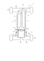
図5を参照にして、二液混合容器1の液室を開封するには、蓋部材3を上方へ向けて、容器本体2若しくは翼部22を一方の手で掴み、他方の手で蓋部材3の翼部14を掴んで、容器本体2と翼部14を逆方向に回転させることにより、脆弱部13を切断する。脆弱部13を切断することによって、容器本体2に接着材の液取り出し開口7bが形成される。この際、翼部14は、両端部にある支持脚部15,15間の距離Lが長いので、回転モーメントが大きくなって小さな力で脆弱部13を切断できる。
蓋部材3を容器本体2から分離させた後は、翼部14の向きを容器本体2の翼部22に対して90度、周方向にずらす位置に回転させる。そして、液室開閉部材4の直下方に蓋部材3を持って行き、液室開閉部材4の下部に設けられているスリット26に差し込む。すると、二液混合容器1がロケット形状に連結され、二液混合容器1の下部は、翼部22と翼部14とで十字形状に形成される。
Referring to FIG. 5, in order to open the liquid chamber of the two-
After the
このように、容器本体2が液取り出し開口7bを上方へ向けた状態で、適当な位置に二液混合容器1を置くことによって、容器1は安定した起立姿勢を維持することができる。この容器本体2に対する蓋部材3の組み付け時においては、スリット26を目標位置に定め、容易に翼部14,22を十字形状に形成できる。
したがって、歯科医師は安定状態で置かれた容器本体の取出し開口7bにロッド30の先端部を差し込んで、接着材を取り出すことができ、接着材の取り出し中に容器が傾倒するようなことが防止される。
Thus, the
Therefore, the dentist can insert the distal end portion of the
こうして、歯科医師は容器本体2を適当な場所に立たせ、両手を使って接着材の塗布を患者の歯に施すことができる。治療後は、二液混合容器1を廃棄するが、容器本体2と蓋部材3とが一体的に結合されているので、そのまま破棄すればそれらが分離して廃棄されることがない。通常は、容器本体2から蓋部材3を分離した時点にて、蓋部材3がゴミとなるが、ゴミになる前に蓋部材3の有効利用を図ることができる。
翼部22と翼部14を十字形状にした場合は、二液混合容器1の縦・横のいずれの方向にも嵩張るが、二液混合容器1の未使用状態では、翼部14と翼部22との位置関係がほぼ平面形状となるので、翼部14,22を寝かせた状態では、翼部14,22の厚さよりも、液室開閉部材4の筒部5の厚さが最も厚くなる。未使用時に多数の二液混合容器1の幾つかを1箱に梱包するようなときは、容器1の全体の梱包を薄くすることができ、例えば、二液混合容器1を倒した姿勢で重ね合わせることによって、少ない梱包容積に多数の二液混合容器1を収容することができる。
In this way, the dentist can stand the
When the
以上、本発明の実施の形態について説明したが、本発明の技術的思想に基づいて、勿論、本発明は種々の変形又は変更が可能である。
例えば、上記実施形態では歯科用接着材を入れる歯科用容器として説明したが、容器の用途には歯科用容器に限定されず、起立姿勢が安定しない他の容器にも適用することができる。
また、上記実施形態では、容器本体2と蓋部材3との結合を脆弱部13によって形成し、脆弱部13を破断するようにしたが、蓋部材3についてはネジ式の蓋部材あるいは、差し込み(嵌合)式の蓋部材にも適用が可能である。
翼部22の延在方向の中間部上面に形成される一対の係止部24は、容器本体2の筒部5の周方向に対して所定の間隔を空けて3本以上設けて、液室開閉部材4の後退位置の規制をより強固に行っても良く、さらには、該筒部5を環囲する態様で設けても良い。
While the embodiments of the present invention have been described above, the present invention can of course be modified or changed in various ways based on the technical idea of the present invention.
For example, although the said embodiment demonstrated as a dental container which puts a dental adhesive material, it is not limited to a dental container for the use of a container, It can apply also to the other container whose standing posture is not stabilized.
Moreover, in the said embodiment, although the coupling | bonding of the container
Three or more pairs of locking
液室7,8の数は本実施形態では2としたが、3以上であってもよく、三液以上を混合して使用する接着材等の容器としても良い。
また、上記実施形態では、第1液室7に脆弱部13を形成し、これを破断して液取り出し開口7bを形成したが、この液取り出し開口7bを形成することなく、容器本体2から液室開閉部材4を取り外して、混合室20(液注入開口7a,8a)側から混合液を取り出すようにしてもよい。この場合は、本発明では液取り出し開口と液注入開口が同じになる。また、この場合は、係止部24を省略してもよい。
Although the number of the
Moreover, in the said embodiment, although the
1 二液混合容器
2 容器本体
3 蓋部材
4 液室開閉部材
5 筒部
6 液室形成部
7 第1液室
7a,8a 液注入開口
7b 液取出開口
8 第2液室
10 蓋本体
12 環状突部
13 脆弱部
14,22 翼部
15 支持脚部(第2の支持部)
17 基部
18,19 封止部材
20 混合室
23 支持脚部(第1の支持部)
24 係止部(引掛け部材)
24a 爪
24b 傾斜面
DESCRIPTION OF
17
24 Locking part (hanging member)
Claims (3)
前記液注入開口を介して各液室と連通する混合室とを有する容器本体と、
該容器本体の混合室に装着され、前記各液室と混合室とを閉塞状態若しくは連通状態に切り替え可能な液室開閉部材とを備えた液混合容器において、
前記液室開閉部材には、前記液注入開口に進入する前進位置で前記注入開口を閉じて前記液室を個々に閉塞し、後退位置で前記注入開口を開放して前記各液室を混合室と連通させる封止部材を設け、
前記液注入開口に挿通可能になるよう前記封止部材を凸形状に突出させ、前記後退位置で前記封止部材を前記容器本体に対して周方向に回転させることによって、前記混合室の液を撹拌可能にしたことを特徴とする液混合容器。 A plurality of liquid chambers provided with liquid injection openings at one end;
A container body having a front Symbol injection opening via the respective liquid chambers and the mixing chamber communicating,
It is attached to the mixing chamber of the container body, in the liquid mixing vessel with a liquid chamber opening and closing member capable of switching the mixing chamber and pre-Symbol respective liquid chambers in the closed state or communicating state,
In the liquid chamber opening / closing member, the liquid injection chamber is individually closed by closing the injection opening at the forward position entering the liquid injection opening, and the injection openings are opened at the backward position to mix the liquid chambers. Providing a sealing member to communicate with
By projecting the sealing member into a convex shape so that it can be inserted into the liquid injection opening, and rotating the sealing member in the circumferential direction with respect to the container body at the retracted position, the liquid in the mixing chamber is A liquid mixing container characterized in that stirring is possible .
前記液注入開口を介して各液室と連通する混合室とを有する容器本体と、
該容器本体の混合室に装着され、前記各液室と混合室とを閉塞状態若しくは連通状態に切り替え可能な液室開閉部材とを備えた液混合容器において、
前記液室開閉部材には、前記液注入開口に進入する前進位置で前記注入開口を閉じて前記液室を個々に閉塞し、後退位置で前記注入開口を開放して前記各液室を混合室と連通させる封止部材を設け、
前記容器本体には、前記液注入開口が設けられた位置とは反対側の前記液室の他端側に液取り出し開口を形成するとともに、該液取り出し開口を閉塞する蓋材が取付けられてなることを特徴とする液混合容器。 A plurality of liquid chambers provided with liquid injection openings at one end;
A container body having a mixing chamber in communication with each liquid chamber through the liquid injection opening;
In a liquid mixing container equipped with a liquid chamber opening and closing member attached to the mixing chamber of the container body and capable of switching each liquid chamber and the mixing chamber to a closed state or a communication state,
In the liquid chamber opening / closing member, the liquid injection chamber is individually closed by closing the injection opening at the forward position entering the liquid injection opening, and the injection openings are opened at the backward position to mix the liquid chambers. Providing a sealing member to communicate with
The container body is formed with a liquid outlet opening at the other end of the liquid chamber opposite to the position where the liquid inlet opening is provided, and a lid member for closing the liquid outlet opening is attached. liquid mixing container you wherein a.
Priority Applications (5)
| Application Number | Priority Date | Filing Date | Title |
|---|---|---|---|
| JP2009206226A JP5467822B2 (en) | 2009-09-07 | 2009-09-07 | Liquid mixing container |
| CN2010800392455A CN102482025A (en) | 2009-09-07 | 2010-08-20 | Liquid mixing container |
| EP10813623A EP2476632A1 (en) | 2009-09-07 | 2010-08-20 | Liquid mixing container |
| PCT/JP2010/064091 WO2011027674A1 (en) | 2009-09-07 | 2010-08-20 | Liquid mixing container |
| US13/394,260 US20120160718A1 (en) | 2009-09-07 | 2010-08-20 | Liquid mixing container |
Applications Claiming Priority (1)
| Application Number | Priority Date | Filing Date | Title |
|---|---|---|---|
| JP2009206226A JP5467822B2 (en) | 2009-09-07 | 2009-09-07 | Liquid mixing container |
Publications (3)
| Publication Number | Publication Date |
|---|---|
| JP2011057238A JP2011057238A (en) | 2011-03-24 |
| JP2011057238A5 JP2011057238A5 (en) | 2012-09-20 |
| JP5467822B2 true JP5467822B2 (en) | 2014-04-09 |
Family
ID=43649213
Family Applications (1)
| Application Number | Title | Priority Date | Filing Date |
|---|---|---|---|
| JP2009206226A Active JP5467822B2 (en) | 2009-09-07 | 2009-09-07 | Liquid mixing container |
Country Status (5)
| Country | Link |
|---|---|
| US (1) | US20120160718A1 (en) |
| EP (1) | EP2476632A1 (en) |
| JP (1) | JP5467822B2 (en) |
| CN (1) | CN102482025A (en) |
| WO (1) | WO2011027674A1 (en) |
Families Citing this family (1)
| Publication number | Priority date | Publication date | Assignee | Title |
|---|---|---|---|---|
| US10729850B1 (en) | 2019-11-15 | 2020-08-04 | King Saud University | Modular dental material dispenser |
Family Cites Families (19)
| Publication number | Priority date | Publication date | Assignee | Title |
|---|---|---|---|---|
| US3696919A (en) * | 1970-10-08 | 1972-10-10 | Colgate Palmolive Co | Double container with mixing means |
| JPS537952Y2 (en) * | 1971-05-20 | 1978-02-28 | ||
| US3856138A (en) * | 1973-05-31 | 1974-12-24 | Shionogi & Co | Compartmentalized container |
| US4410085A (en) * | 1982-05-03 | 1983-10-18 | Manufacture Lyonnaise De Bouchage | Drinking goblet enabling two doses of constituents to be mixed just before consumption |
| US4550825A (en) * | 1983-07-27 | 1985-11-05 | The West Company | Multicompartment medicament container |
| JPH0533153Y2 (en) * | 1990-07-05 | 1993-08-24 | ||
| JPH0435575U (en) * | 1990-07-18 | 1992-03-25 | ||
| JPH11130156A (en) * | 1997-10-27 | 1999-05-18 | Shiseido Co Ltd | Double-pack mixing container, and double-pack mixing container connector |
| AU2001296764A1 (en) | 2000-10-13 | 2002-04-22 | Dentsply International Inc. | Multi-component mixing storage and dispensing device |
| JP4357920B2 (en) | 2003-09-30 | 2009-11-04 | 株式会社ジーシー | Two-component mixing container |
| KR100622282B1 (en) * | 2004-08-19 | 2006-09-19 | 오종석 | Medicine Bottle for Injection |
| EP1728560A1 (en) * | 2005-06-03 | 2006-12-06 | 3M Innovative Properties Company | System for storing and dispensing of a substance |
| EP2013112A4 (en) * | 2006-03-20 | 2010-06-16 | Nordson Corp | Propellant actuated dual fluid cartridge |
| US8104609B2 (en) * | 2007-03-08 | 2012-01-31 | Tokuyama Dental Corporation | Container |
| JP5110920B2 (en) * | 2007-03-08 | 2012-12-26 | 株式会社トクヤマデンタル | container |
| JP4944671B2 (en) * | 2007-05-22 | 2012-06-06 | 株式会社トクヤマデンタル | container |
| US8104611B2 (en) * | 2007-08-09 | 2012-01-31 | Helou Jr Elie | Mixing container and method of filling |
| WO2009105262A1 (en) * | 2008-02-21 | 2009-08-27 | Chen, Chung, Chin | Container structure for contain different beverages |
| US8083056B1 (en) * | 2011-03-14 | 2011-12-27 | Kuo Chen Wu | Container |
-
2009
- 2009-09-07 JP JP2009206226A patent/JP5467822B2/en active Active
-
2010
- 2010-08-20 WO PCT/JP2010/064091 patent/WO2011027674A1/en active Application Filing
- 2010-08-20 EP EP10813623A patent/EP2476632A1/en not_active Withdrawn
- 2010-08-20 CN CN2010800392455A patent/CN102482025A/en active Pending
- 2010-08-20 US US13/394,260 patent/US20120160718A1/en not_active Abandoned
Also Published As
| Publication number | Publication date |
|---|---|
| JP2011057238A (en) | 2011-03-24 |
| US20120160718A1 (en) | 2012-06-28 |
| WO2011027674A1 (en) | 2011-03-10 |
| EP2476632A1 (en) | 2012-07-18 |
| CN102482025A (en) | 2012-05-30 |
Similar Documents
| Publication | Publication Date | Title |
|---|---|---|
| EP1968751B1 (en) | Dispensing device for single use | |
| JP4722852B2 (en) | Unit amount lock case | |
| US8365958B2 (en) | Device for mixing and discharging plural materials | |
| US9131930B2 (en) | Devices for filling a multi-use syringe or single-use syringe | |
| EP2421464B1 (en) | Dispensing device for a dental substance | |
| JP6111205B2 (en) | Lid and container assembly for compounded products | |
| KR200256383Y1 (en) | A case cam use separayion charge and mix to powder or solution of different each otater ponenit | |
| US9381480B2 (en) | Container for mixing two different types of solutions | |
| WO2009104099A3 (en) | Disposable shaker | |
| KR20070004854A (en) | Package assembly for dental substances | |
| JP6271549B2 (en) | Reconstruction device | |
| WO2009027981A2 (en) | Multi-compartment container system | |
| US20060157503A1 (en) | Device for storing and dispensing fluid substances | |
| JP5467822B2 (en) | Liquid mixing container | |
| US11141022B2 (en) | Container unit comprising two containers | |
| JP2007153405A (en) | Two-component mixing container | |
| EP4032498A1 (en) | An apparatus for activating a cartridge comprising a multi-component material and/or for mixing by vibration said cartridge | |
| KR101477332B1 (en) | Device for mixing and discharging plural materials | |
| EP2874594B1 (en) | Reconstitution device with tip cap | |
| JP5485559B2 (en) | Medical paste injection kneader | |
| JP2007112459A (en) | Two component mixing container | |
| JP2005096862A (en) | Cap having removing member and medicine storage container | |
| TWM246309U (en) | Container device with separating storage structure | |
| JP2012206027A (en) | Mixing and spouting container | |
| KR20110120177A (en) | Reusable dissimilar material mixing container with lid as a medium |
Legal Events
| Date | Code | Title | Description |
|---|---|---|---|
| A521 | Request for written amendment filed |
Free format text: JAPANESE INTERMEDIATE CODE: A523 Effective date: 20120806 |
|
| A621 | Written request for application examination |
Free format text: JAPANESE INTERMEDIATE CODE: A621 Effective date: 20120806 |
|
| A131 | Notification of reasons for refusal |
Free format text: JAPANESE INTERMEDIATE CODE: A131 Effective date: 20131008 |
|
| A521 | Request for written amendment filed |
Free format text: JAPANESE INTERMEDIATE CODE: A523 Effective date: 20131206 |
|
| TRDD | Decision of grant or rejection written | ||
| A01 | Written decision to grant a patent or to grant a registration (utility model) |
Free format text: JAPANESE INTERMEDIATE CODE: A01 Effective date: 20140107 |
|
| A61 | First payment of annual fees (during grant procedure) |
Free format text: JAPANESE INTERMEDIATE CODE: A61 Effective date: 20140128 |
|
| R150 | Certificate of patent or registration of utility model |
Ref document number: 5467822 Country of ref document: JP Free format text: JAPANESE INTERMEDIATE CODE: R150 Free format text: JAPANESE INTERMEDIATE CODE: R150 |
|
| R250 | Receipt of annual fees |
Free format text: JAPANESE INTERMEDIATE CODE: R250 |
|
| R250 | Receipt of annual fees |
Free format text: JAPANESE INTERMEDIATE CODE: R250 |
|
| R250 | Receipt of annual fees |
Free format text: JAPANESE INTERMEDIATE CODE: R250 |