EP2874594B1 - Reconstitution device with tip cap - Google Patents
Reconstitution device with tip cap Download PDFInfo
- Publication number
- EP2874594B1 EP2874594B1 EP13819751.2A EP13819751A EP2874594B1 EP 2874594 B1 EP2874594 B1 EP 2874594B1 EP 13819751 A EP13819751 A EP 13819751A EP 2874594 B1 EP2874594 B1 EP 2874594B1
- Authority
- EP
- European Patent Office
- Prior art keywords
- syringe
- vial
- transfer
- moveable member
- housing
- Prior art date
- Legal status (The legal status is an assumption and is not a legal conclusion. Google has not performed a legal analysis and makes no representation as to the accuracy of the status listed.)
- Active
Links
- 239000003085 diluting agent Substances 0.000 claims description 5
- 238000003780 insertion Methods 0.000 claims description 3
- 230000037431 insertion Effects 0.000 claims description 3
- 239000000306 component Substances 0.000 description 6
- 239000007788 liquid Substances 0.000 description 6
- 238000002347 injection Methods 0.000 description 4
- 239000007924 injection Substances 0.000 description 4
- 239000000203 mixture Substances 0.000 description 4
- 238000011109 contamination Methods 0.000 description 2
- 239000012530 fluid Substances 0.000 description 2
- 239000005426 pharmaceutical component Substances 0.000 description 2
- 230000004075 alteration Effects 0.000 description 1
- POIUWJQBRNEFGX-XAMSXPGMSA-N cathelicidin Chemical compound C([C@@H](C(=O)N[C@@H](CCCNC(N)=N)C(=O)N[C@@H](CCCCN)C(=O)N[C@@H](CO)C(=O)N[C@@H](CCCCN)C(=O)N[C@@H](CCC(O)=O)C(=O)N[C@@H](CCCCN)C(=O)N[C@@H]([C@@H](C)CC)C(=O)NCC(=O)N[C@@H](CCCCN)C(=O)N[C@@H](CCC(O)=O)C(=O)N[C@@H](CC=1C=CC=CC=1)C(=O)N[C@@H](CCCCN)C(=O)N[C@@H](CCCNC(N)=N)C(=O)N[C@@H]([C@@H](C)CC)C(=O)N[C@@H](C(C)C)C(=O)N[C@@H](CCC(N)=O)C(=O)N[C@@H](CCCNC(N)=N)C(=O)N[C@@H]([C@@H](C)CC)C(=O)N[C@@H](CCCCN)C(=O)N[C@@H](CC(O)=O)C(=O)N[C@@H](CC=1C=CC=CC=1)C(=O)N[C@@H](CC(C)C)C(=O)N[C@@H](CCCNC(N)=N)C(=O)N[C@@H](CC(N)=O)C(=O)N[C@@H](CC(C)C)C(=O)N[C@@H](C(C)C)C(=O)N1[C@@H](CCC1)C(=O)N[C@@H](CCCNC(N)=N)C(=O)N[C@@H]([C@@H](C)O)C(=O)N[C@@H](CCC(O)=O)C(=O)N[C@@H](CO)C(O)=O)NC(=O)[C@H](CC=1C=CC=CC=1)NC(=O)[C@H](CC(O)=O)NC(=O)CNC(=O)[C@H](CC(C)C)NC(=O)[C@@H](N)CC(C)C)C1=CC=CC=C1 POIUWJQBRNEFGX-XAMSXPGMSA-N 0.000 description 1
- 239000004615 ingredient Substances 0.000 description 1
- 239000000463 material Substances 0.000 description 1
- 238000000034 method Methods 0.000 description 1
- 238000012986 modification Methods 0.000 description 1
- 230000004048 modification Effects 0.000 description 1
- 230000000149 penetrating effect Effects 0.000 description 1
- 239000000825 pharmaceutical preparation Substances 0.000 description 1
- 229920001296 polysiloxane Polymers 0.000 description 1
- 238000007789 sealing Methods 0.000 description 1
- 239000007787 solid Substances 0.000 description 1
Images


Classifications
-
- A—HUMAN NECESSITIES
- A61—MEDICAL OR VETERINARY SCIENCE; HYGIENE
- A61J—CONTAINERS SPECIALLY ADAPTED FOR MEDICAL OR PHARMACEUTICAL PURPOSES; DEVICES OR METHODS SPECIALLY ADAPTED FOR BRINGING PHARMACEUTICAL PRODUCTS INTO PARTICULAR PHYSICAL OR ADMINISTERING FORMS; DEVICES FOR ADMINISTERING FOOD OR MEDICINES ORALLY; BABY COMFORTERS; DEVICES FOR RECEIVING SPITTLE
- A61J1/00—Containers specially adapted for medical or pharmaceutical purposes
- A61J1/14—Details; Accessories therefor
- A61J1/20—Arrangements for transferring or mixing fluids, e.g. from vial to syringe
- A61J1/2096—Combination of a vial and a syringe for transferring or mixing their contents
-
- A—HUMAN NECESSITIES
- A61—MEDICAL OR VETERINARY SCIENCE; HYGIENE
- A61J—CONTAINERS SPECIALLY ADAPTED FOR MEDICAL OR PHARMACEUTICAL PURPOSES; DEVICES OR METHODS SPECIALLY ADAPTED FOR BRINGING PHARMACEUTICAL PRODUCTS INTO PARTICULAR PHYSICAL OR ADMINISTERING FORMS; DEVICES FOR ADMINISTERING FOOD OR MEDICINES ORALLY; BABY COMFORTERS; DEVICES FOR RECEIVING SPITTLE
- A61J1/00—Containers specially adapted for medical or pharmaceutical purposes
- A61J1/14—Details; Accessories therefor
- A61J1/20—Arrangements for transferring or mixing fluids, e.g. from vial to syringe
- A61J1/2003—Accessories used in combination with means for transfer or mixing of fluids, e.g. for activating fluid flow, separating fluids, filtering fluid or venting
- A61J1/2006—Piercing means
- A61J1/201—Piercing means having one piercing end
-
- A—HUMAN NECESSITIES
- A61—MEDICAL OR VETERINARY SCIENCE; HYGIENE
- A61M—DEVICES FOR INTRODUCING MEDIA INTO, OR ONTO, THE BODY; DEVICES FOR TRANSDUCING BODY MEDIA OR FOR TAKING MEDIA FROM THE BODY; DEVICES FOR PRODUCING OR ENDING SLEEP OR STUPOR
- A61M5/00—Devices for bringing media into the body in a subcutaneous, intra-vascular or intramuscular way; Accessories therefor, e.g. filling or cleaning devices, arm-rests
- A61M5/178—Syringes
- A61M5/31—Details
- A61M5/32—Needles; Details of needles pertaining to their connection with syringe or hub; Accessories for bringing the needle into, or holding the needle on, the body; Devices for protection of needles
- A61M5/34—Constructions for connecting the needle, e.g. to syringe nozzle or needle hub
- A61M5/343—Connection of needle cannula to needle hub, or directly to syringe nozzle without a needle hub
-
- A—HUMAN NECESSITIES
- A61—MEDICAL OR VETERINARY SCIENCE; HYGIENE
- A61J—CONTAINERS SPECIALLY ADAPTED FOR MEDICAL OR PHARMACEUTICAL PURPOSES; DEVICES OR METHODS SPECIALLY ADAPTED FOR BRINGING PHARMACEUTICAL PRODUCTS INTO PARTICULAR PHYSICAL OR ADMINISTERING FORMS; DEVICES FOR ADMINISTERING FOOD OR MEDICINES ORALLY; BABY COMFORTERS; DEVICES FOR RECEIVING SPITTLE
- A61J1/00—Containers specially adapted for medical or pharmaceutical purposes
- A61J1/14—Details; Accessories therefor
- A61J1/20—Arrangements for transferring or mixing fluids, e.g. from vial to syringe
- A61J1/2003—Accessories used in combination with means for transfer or mixing of fluids, e.g. for activating fluid flow, separating fluids, filtering fluid or venting
- A61J1/2048—Connecting means
- A61J1/2051—Connecting means having tap means, e.g. tap means activated by sliding
-
- A—HUMAN NECESSITIES
- A61—MEDICAL OR VETERINARY SCIENCE; HYGIENE
- A61J—CONTAINERS SPECIALLY ADAPTED FOR MEDICAL OR PHARMACEUTICAL PURPOSES; DEVICES OR METHODS SPECIALLY ADAPTED FOR BRINGING PHARMACEUTICAL PRODUCTS INTO PARTICULAR PHYSICAL OR ADMINISTERING FORMS; DEVICES FOR ADMINISTERING FOOD OR MEDICINES ORALLY; BABY COMFORTERS; DEVICES FOR RECEIVING SPITTLE
- A61J1/00—Containers specially adapted for medical or pharmaceutical purposes
- A61J1/14—Details; Accessories therefor
- A61J1/20—Arrangements for transferring or mixing fluids, e.g. from vial to syringe
- A61J1/2003—Accessories used in combination with means for transfer or mixing of fluids, e.g. for activating fluid flow, separating fluids, filtering fluid or venting
- A61J1/2048—Connecting means
- A61J1/2055—Connecting means having gripping means
-
- A—HUMAN NECESSITIES
- A61—MEDICAL OR VETERINARY SCIENCE; HYGIENE
- A61M—DEVICES FOR INTRODUCING MEDIA INTO, OR ONTO, THE BODY; DEVICES FOR TRANSDUCING BODY MEDIA OR FOR TAKING MEDIA FROM THE BODY; DEVICES FOR PRODUCING OR ENDING SLEEP OR STUPOR
- A61M5/00—Devices for bringing media into the body in a subcutaneous, intra-vascular or intramuscular way; Accessories therefor, e.g. filling or cleaning devices, arm-rests
- A61M5/178—Syringes
- A61M5/31—Details
- A61M5/3129—Syringe barrels
- A61M5/3137—Specially designed finger grip means, e.g. for easy manipulation of the syringe rod
-
- A—HUMAN NECESSITIES
- A61—MEDICAL OR VETERINARY SCIENCE; HYGIENE
- A61M—DEVICES FOR INTRODUCING MEDIA INTO, OR ONTO, THE BODY; DEVICES FOR TRANSDUCING BODY MEDIA OR FOR TAKING MEDIA FROM THE BODY; DEVICES FOR PRODUCING OR ENDING SLEEP OR STUPOR
- A61M5/00—Devices for bringing media into the body in a subcutaneous, intra-vascular or intramuscular way; Accessories therefor, e.g. filling or cleaning devices, arm-rests
- A61M5/178—Syringes
- A61M5/31—Details
- A61M5/315—Pistons; Piston-rods; Guiding, blocking or restricting the movement of the rod or piston; Appliances on the rod for facilitating dosing ; Dosing mechanisms
- A61M5/31501—Means for blocking or restricting the movement of the rod or piston
- A61M5/31505—Integral with the syringe barrel, i.e. connected to the barrel so as to make up a single complete piece or unit
Definitions
- the present invention relates to a reconstitution system and more particularly, relates to a reconstitution system utilizing a syringe.
- a syringe is filled manually by aspirating a liquid pharmaceutical component from a pharmaceutical vial which has a penetrable closure.
- the syringe has a needle that penetrates the penetrable closure following which the syringe is typically filled by drawing air into the body of the syringe, aligning the needle with the vial's penetrable closure and inserting the needle through the penetrable closure into the vial.
- the vial is inverted and air is forced from the body of the syringe into the body of the vial.
- the plunger is then withdrawn to draw out the desired volume of the pharmaceutical component into the syringe and the needle is removed from the vial.
- the needle typically, many procedures call for the needle to be removed from the syringe since there is danger of contamination of the needle. Furthermore, the silicone on the needle may be removed during the act of penetrating the vial.
- a transfer arrangement as claimed in claim 1 comprising a syringe, the syringe having a side wall defining a cavity, the syringe having first and second syringe ends, the first syringe end being open, a plunger mounted within the syringe to thereby seal the first syringe end, a needle connected to the second syringe end, an adaptor having first and second adaptor ends, the first adaptor end being designed to connect to the second syringe end, the adaptor extending about the needle to prevent access thereto, the second adaptor end having a luer connector, and a transfer member, the transfer member having first and second transfer member ends, the first transfer member end being connectable to the second adaptor end, the second transfer member end being arranged to receive a neck of a vial.
- the syringe utilized in the present invention may be of the conventional type.
- the syringe would have a first end with a needle located thereat with a second opened end.
- a plunger is mounted within the syringe to contain the material therein in a conventional manner.
- the needle may be of the staked-in type - i.e. permanently fixed to the end and communicating with the interior of the syringe.
- the transfer arrangement also includes an adaptor with a first end of the adaptor being designed to connect to the syringe end having the needle.
- the adaptor extends about the needle to prevent access thereto. This is a safety measure to prevent accidental pricking.
- the opposite adaptor end preferably has a luer connection.
- the transfer arrangement When not in use, the transfer arrangement also preferably includes a tip cap which fits within the adaptor end having the luer connector.
- the transfer arrangement also includes a transfer member which has first and second transfer member ends, the first transfer member end being connectable to the adaptor end after removal of the tip cap, the second transfer member end being designed to receive the neck of a vial.
- a plunger rod which is connectable to the plunger.
- a back stop connected to the syringe proximate the first syringe for aiding in the movement of the plunger rod.
- Vial 12 has a body 14 with a neck sealed by a septum 16 over which there is a cap 18.
- a medicant 20 is contained within body 14 and would typically comprise a dry ingredient although a fluid may also be utilized.
- Transfer system 10 includes an outer housing 24 and a circular side wall 26. On circular side wall 26 there is a protrusion 28 near the bottom thereof. On its upper end, there is provided a luer connection 30. An inner wall 32 mounts a needle 34 which is hollow in nature and has a piercing end 36. As previously mentioned, needle 34 may be a spike.
- Moveable member 40 Mounted interiorly of outer housing 24 is a moveable member 40.
- Moveable member 40 has a top wall 42 with an aperture 44 centrally located therein to permit the passage of needle 34.
- Extending downwardly from top wall 42 is a first leg 46 and a second leg 48.
- First leg 46 has an outwardly extending flange 50 at the bottom thereof while second leg 48 also has an outwardly extending flange 52.
- a cover 56 is provided to receive transfer system 10.
- Cover 56 has a side wall 57 which is adapted to engage with protrusion 28 to retain transfer system 10 in position.
- Side wall 57 is provided with an outwardly extending flange 60 at the bottom thereof.
- Flange 60 is designed to receive a peelable sealing strip 62 so as to provide a hermetically sealed package.
- a transfer system is preferably utilized with a syringe which has a syringe body 66 and a plunger 68 mounted therein.
- a plunger rod 70 is designed to be screwthreadably engageable with plunger 68.
- Syringe body 66 includes a backstop 72 to permit proper gripping by the hand of a user.
- syringe body 68 includes a luer connector 74.
- syringe body 66 is filled with a diluent 76 although any desired fluid may be utilized.
- plunger rod 70 is connected to plunger 68 and the diluent 76 is then forced into vial body 14 as shown in Figure 10 .
- the medicant and diluent may then be mixed and the assembly inverted as shown in Figure 11 .
- the mixture 80 is then aspirated back into syringe body 66.
- the mixture 80 is then ready for injection when a needle assembly is connected to luer connector 74.
- outer housing 24 is provided with a pair of apertures 86 in side wall 26. Also, in this embodiment, there are provided an extra pair of legs 87 each having buttons 88 formed on an exterior surface thereof. In this embodiment, when the moveable member 40 moves upwardly, buttons 88 engage in apertures 86.
- ribs 90 which have a groove 92 formed therein.
- top wall 42 is provided with protrusions 96 and locking latches 98.
- the present invention utilizes a syringe generally designated by reference numeral 110.
- Syringe 110 is provided with a back stop 112 as is known in the art.
- a plunger 114 seals a first syringe end 111 and defines a compartment 116 which will contain the liquid diluent.
- a plunger rod 118 is used to advance plunger 114 when required.
- a staked-in needle 119 At the second end forming the injection end 113, there is provided a staked-in needle 119 and a needle shield 120.
- a tip cap 122 extends over needle 119.
- An adaptor generally designated by reference numeral 124 has first and second ends 121, 123 respectively with an internal luer connector 126 being located at second adaptor end 123.
- a transfer member 128 as previously described in Figures 1 to 19 and which has first and second transfer member ends 131 and 133.
- a vial 130 contains the dry component 135 to be mixed with the liquid in compartment 116 of syringe 110.
- transfer system 128 is placed over the top of vial 130 as shown in Figure 22 . Subsequently, tip cap 122 is removed. As seen in Figure 24 , transfer system 128 is then connected via luer connector to syringe 110. As shown in Figure 25 , the reconstitution is then begun with initial downward movement to transfer the liquid into vial 130 and subsequent aspiration to bring the mixture back into syringe 110.
- the needle used for injection is protected at all times. Thus, there is no risk of damage to needle 119 nor to the possibility of contaminates entering the system.
Description
- The present invention relates to a reconstitution system and more particularly, relates to a reconstitution system utilizing a syringe.
- Typically, a syringe is filled manually by aspirating a liquid pharmaceutical component from a pharmaceutical vial which has a penetrable closure. The syringe has a needle that penetrates the penetrable closure following which the syringe is typically filled by drawing air into the body of the syringe, aligning the needle with the vial's penetrable closure and inserting the needle through the penetrable closure into the vial. Subsequently, the vial is inverted and air is forced from the body of the syringe into the body of the vial. The plunger is then withdrawn to draw out the desired volume of the pharmaceutical component into the syringe and the needle is removed from the vial.
- The above reconstitution is done since many pharmaceutical preparations must be distributed and sold as two separate components - typically a solid component and a liquid component. They are mixed just prior to administration. Actually, two or more components may each be liquid.
- Typically, many procedures call for the needle to be removed from the syringe since there is danger of contamination of the needle. Furthermore, the silicone on the needle may be removed during the act of penetrating the vial.
- Document
US20060184103 discloses a transfer arrangement including all the technical features of the preamble of claim 1. - It is an object of the present invention to provide an assembly for transferring the contents of the first container to a second container without contamination or alteration of the needle.
- According to one aspect of the present invention, there is provided a transfer arrangement as claimed in claim 1 comprising a syringe, the syringe having a side wall defining a cavity, the syringe having first and second syringe ends, the first syringe end being open, a plunger mounted within the syringe to thereby seal the first syringe end, a needle connected to the second syringe end, an adaptor having first and second adaptor ends, the first adaptor end being designed to connect to the second syringe end, the adaptor extending about the needle to prevent access thereto, the second adaptor end having a luer connector, and a transfer member, the transfer member having first and second transfer member ends, the first transfer member end being connectable to the second adaptor end, the second transfer member end being arranged to receive a neck of a vial.
- The syringe utilized in the present invention may be of the conventional type. Thus, the syringe would have a first end with a needle located thereat with a second opened end. A plunger is mounted within the syringe to contain the material therein in a conventional manner. The needle may be of the staked-in type - i.e. permanently fixed to the end and communicating with the interior of the syringe.
- The transfer arrangement also includes an adaptor with a first end of the adaptor being designed to connect to the syringe end having the needle. The adaptor extends about the needle to prevent access thereto. This is a safety measure to prevent accidental pricking. The opposite adaptor end preferably has a luer connection.
- When not in use, the transfer arrangement also preferably includes a tip cap which fits within the adaptor end having the luer connector.
- The transfer arrangement also includes a transfer member which has first and second transfer member ends, the first transfer member end being connectable to the adaptor end after removal of the tip cap, the second transfer member end being designed to receive the neck of a vial.
- As is utilized in most syringe arrangements, there is provided a plunger rod which is connectable to the plunger. For operational purposes, there is preferably also provided a back stop connected to the syringe proximate the first syringe for aiding in the movement of the plunger rod.
- Having thus generally described the invention, reference will be made to the accompanying drawings illustrating an embodiment thereof, in which:
-
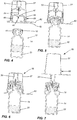
Figure 1 is a side elevational view of a transfer device according to the present invention; -
Figure 2 is a side elevational view, partially in section, of a vial containing a medicant; -
Figure 3 is a side elevational view of a syringe and plunger rod; -
Figure 4 is a cross sectional view of the transfer device prior to its use; -
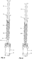
Figure 5 is a side sectional view of the device being placed on a vial; -
Figure 6 is a side sectional view showing piercing of the vial; -
Figure 7 is a cross sectional view illustrating the cap being removed; -
Figure 8 is a cross sectional view illustrating a luer lock syringe being ready to be placed on the vial; -
Figure 9 is a view, partially in cross section, of a luer lock syringe being attached to the transfer device; -
Figure 10 is a sectional view illustrating the mixing of components; -
Figure 11 is a sectional view illustrating the aspiration of the mixture into the syringe; -
Figure 12 is a sectional view showing the syringe being detached; -
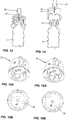
Figure 13 is a cross sectional view illustrating placement of the transfer assembly on a vial; -
Figure 14 is an exploded view illustrating the transfer assembly and the vial prior to insertion of the vial; -
Figure 15A is a bottom perspective view of a transfer assembly according to one embodiment of the present invention; -
Figure 15B is a bottom plan view thereof; -
Figure 16A is a perspective view of the transfer assembly according to a further embodiment; -
Figure 16B is a bottom plan view thereof; -
Figure 17A is an exploded view of the transfer assembly; -
Figure 17B is a bottom perspective view thereof; -
Figures 17C to 17E show the sequence of placing the transfer assembly on the vial; -
Figures 17F to 17H illustrate the placement of the transfer assembly in a further embodiment thereof on a vial; -
Figure 18 is an exploded view of the transfer assembly; and -
Figures 19A to 19D are perspective views illustrating placement of the transfer assembly on a vial and removal thereof. -
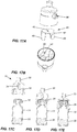
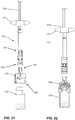
Figure 20 is a view of a staked-in needle syringe using the concept of the present invention; and -
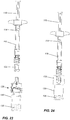
Figures 21 to 28 illustrate use of the system of the present invention. - Referring to the drawings in greater detail and by reference characters thereto, there is illustrated a transfer system which is generally designated by
reference numeral 10 and which is suitable for use with a vial generally designated byreference numeral 12. - Vial 12 has a
body 14 with a neck sealed by aseptum 16 over which there is acap 18. Amedicant 20 is contained withinbody 14 and would typically comprise a dry ingredient although a fluid may also be utilized. -
Transfer system 10 includes anouter housing 24 and acircular side wall 26. Oncircular side wall 26 there is aprotrusion 28 near the bottom thereof. On its upper end, there is provided aluer connection 30. Aninner wall 32 mounts aneedle 34 which is hollow in nature and has apiercing end 36. As previously mentioned,needle 34 may be a spike. - Mounted interiorly of
outer housing 24 is amoveable member 40.Moveable member 40 has atop wall 42 with anaperture 44 centrally located therein to permit the passage ofneedle 34. Extending downwardly fromtop wall 42 is afirst leg 46 and asecond leg 48.First leg 46 has an outwardly extendingflange 50 at the bottom thereof whilesecond leg 48 also has an outwardly extendingflange 52. - A
cover 56 is provided to receivetransfer system 10.Cover 56 has aside wall 57 which is adapted to engage withprotrusion 28 to retaintransfer system 10 in position.Side wall 57 is provided with an outwardly extendingflange 60 at the bottom thereof.Flange 60 is designed to receive apeelable sealing strip 62 so as to provide a hermetically sealed package. - A transfer system is preferably utilized with a syringe which has a
syringe body 66 and aplunger 68 mounted therein. Aplunger rod 70 is designed to be screwthreadably engageable withplunger 68.Syringe body 66 includes abackstop 72 to permit proper gripping by the hand of a user. At its front end,syringe body 68 includes aluer connector 74. Typically,syringe body 66 is filled with a diluent 76 although any desired fluid may be utilized. - As shown in
Figures 8 and 9 ,plunger rod 70 is connected toplunger 68 and the diluent 76 is then forced intovial body 14 as shown inFigure 10 . The medicant and diluent may then be mixed and the assembly inverted as shown inFigure 11 . Themixture 80 is then aspirated back intosyringe body 66. Themixture 80 is then ready for injection when a needle assembly is connected toluer connector 74. - In the embodiment of
Figures 17A to 17H , it will be noted thatouter housing 24 is provided with a pair ofapertures 86 inside wall 26. Also, in this embodiment, there are provided an extra pair oflegs 87 each havingbuttons 88 formed on an exterior surface thereof. In this embodiment, when themoveable member 40 moves upwardly,buttons 88 engage inapertures 86. - On the interior surface of
wall 26, there are providedribs 90 which have agroove 92 formed therein. Thus, when pressure is exerted onbuttons 86 asvial 12 is being withdrawn,moveable member 40 will move downwardly until thetop wall 42 engages withgroove 92. This retainsmoveable member 40 in position for further use. - In the embodiment of
Figures 18 to 19D , it will be noted thattop wall 42 is provided withprotrusions 96 and locking latches 98. On the interior there are providedribs 100 and angledside wall portions 102. The arrangement is such that upon upward movement of moveable member 94,protrusions 96 engage withangled side wall 102 to rotatemoveable member 40. Upon withdrawal, locking latches 98 engage withrib 100 so as to prevent further use of the transfer member. - As shown in
Figure 20 , the present invention utilizes a syringe generally designated byreference numeral 110.Syringe 110 is provided with aback stop 112 as is known in the art. Aplunger 114 seals afirst syringe end 111 and defines acompartment 116 which will contain the liquid diluent. Aplunger rod 118 is used to advanceplunger 114 when required. - At the second end forming the
injection end 113, there is provided a staked-inneedle 119 and aneedle shield 120. Atip cap 122 extends overneedle 119. - An adaptor generally designated by
reference numeral 124 has first and second ends 121, 123 respectively with aninternal luer connector 126 being located atsecond adaptor end 123. - In operation, and as shown in
Figures 21 to 28 , there is provided atransfer member 128 as previously described inFigures 1 to 19 and which has first and second transfer member ends 131 and 133. Avial 130 contains thedry component 135 to be mixed with the liquid incompartment 116 ofsyringe 110. - Initially,
transfer system 128 is placed over the top ofvial 130 as shown inFigure 22 . Subsequently,tip cap 122 is removed. As seen inFigure 24 ,transfer system 128 is then connected via luer connector tosyringe 110. As shown inFigure 25 , the reconstitution is then begun with initial downward movement to transfer the liquid intovial 130 and subsequent aspiration to bring the mixture back intosyringe 110. - Subsequently, as shown in
Figure 26 , the vial andtransfer system 128 are disconnected and then, as shown inFigure 28 ,syringe 110 is ready for injection of its contents. - Using the above system, the needle used for injection is protected at all times. Thus, there is no risk of damage to
needle 119 nor to the possibility of contaminates entering the system. - It will be understood that the above described embodiment is for purposes of illustration only and changes and modifications may be made thereto. Thus, one could use other vial adaptors and one need not necessarily use a cap.
Claims (13)
- A transfer arrangement comprising:a syringe (110), said syringe (110) having a side wall defining a cavity (116), said syringe having first and second syringe ends (111, 113), said first syringe end (111) being open, a plunger (114) mounted within said syringe (110) to thereby seal said first syringe end (111), a needle (119) connected to said second syringe end (113);a backstop (112) connected to said syringe proximate said first syringe end (111);characterized in that it further comprises an adaptor (124) having first and second adaptor ends (121, 123), said first adaptor end (121) being designed to connect to said second syringe end (113), said adaptor extending about said needle (119) to prevent access thereto, said second adaptor end (123) having a female luer connector (126); anda transfer member (128), said transfer member (128) having first and second transfer member ends (131, 133), said first transfer member end (131) being connectable to said second adaptor end (123), said second transfer member end (133) being arranged to receive a neck of a vial (130).
- The transfer arrangement of Claim 1 further including a plunger rod (118) connected to said plunger (114).
- The transfer arrangement of Claim 1 further including a vial (130), said vial (130) being connected to said second transfer member end (133).
- The transfer arrangement of Claim 3 wherein said needle (119) is a staked-in needle.
- The transfer arrangement of Claim 3 wherein said vial contains a medicant (135) and said syringe contains a diluent therefore.
- The transfer arrangement of Claim 1 wherein said transfer device comprises:a housing (24) having a top, a side wall (26), an open bottom, said open bottom permitting insertion of a vial (12) within said housing;a piercing member (34) mounted within said housing (24), said piercing member (34) having a piercing tip (36) located at a bottom end thereof, said piercing member having an interior passageway formed therein;a connector (30) located on an exterior side of said top;a moveable member (40) mounted within said housing (24), said moveable member (40) being moveable from a first position wherein said moveable member (40) prevents access to said piercing tip (36) and a second position permitting access to said piercing tip when said vial is inserted in said housing.
- The transfer device of Claim 6 wherein said moveable member (40) and said housing (24) cause said moveable member (40) to rotate when said moveable member (40) moves upwardly upon insertion of said vial (12), said moveable member returning to a third locked position upon removal of said vial, said third locked position being such that a further vial cannot be inserted into said housing.
- The transfer device of Claim 6 wherein said moveable member includes at least one leg (46), said housing having a recess formed therein, said leg engaging said recess when said moveable member is in said second position, said moveable member being returnable to said first position upon removal of said vial by pressure on said leg to release said leg from said recess.
- The device of Claim 7 wherein said piercing member (34) is selected from the group consisting of a needle or spike.
- The device of Claim 9 wherein said moveable member (40) has a centrally located aperture (44) to permit said piercing member (34) to pass therethrough.
- The device of Claim 7 wherein said connector (30) on the exterior side of said top comprises a luer connector.
- The device of Claim 8 wherein said moveable member (40) has two projections, each projection being located on a respective one of diametrically opposite legs.
- The device of Claim 12 wherein said housing (24) has a recess formed on an interior surface thereof to receive a disc portion of said moveable member (40) when said moveable member is in said first position.
Applications Claiming Priority (2)
| Application Number | Priority Date | Filing Date | Title |
|---|---|---|---|
| CA2783251A CA2783251A1 (en) | 2012-07-17 | 2012-07-17 | Reconstitution device with tip cap |
| PCT/CA2013/000629 WO2014012162A1 (en) | 2012-07-17 | 2013-07-11 | Reconstitution device with tip cap |
Publications (3)
| Publication Number | Publication Date |
|---|---|
| EP2874594A1 EP2874594A1 (en) | 2015-05-27 |
| EP2874594A4 EP2874594A4 (en) | 2016-03-02 |
| EP2874594B1 true EP2874594B1 (en) | 2017-01-04 |
Family
ID=49943671
Family Applications (1)
| Application Number | Title | Priority Date | Filing Date |
|---|---|---|---|
| EP13819751.2A Active EP2874594B1 (en) | 2012-07-17 | 2013-07-11 | Reconstitution device with tip cap |
Country Status (7)
| Country | Link |
|---|---|
| US (1) | US9956142B2 (en) |
| EP (1) | EP2874594B1 (en) |
| CN (1) | CN104640533B (en) |
| CA (2) | CA2783251A1 (en) |
| ES (1) | ES2616478T3 (en) |
| IN (1) | IN2015DN00361A (en) |
| WO (1) | WO2014012162A1 (en) |
Families Citing this family (1)
| Publication number | Priority date | Publication date | Assignee | Title |
|---|---|---|---|---|
| US10143625B2 (en) | 2015-03-17 | 2018-12-04 | Recon Therapeutics, Inc. | Pharmaceutical reconstitution |
Family Cites Families (7)
| Publication number | Priority date | Publication date | Assignee | Title |
|---|---|---|---|---|
| FR2726768A1 (en) * | 1994-11-14 | 1996-05-15 | Debiotech Sa | SYRINGE DEVICE ATTACHABLE TO A VIAL |
| GB9701413D0 (en) * | 1997-01-24 | 1997-03-12 | Smithkline Beecham Biolog | Novel device |
| US6159192A (en) * | 1997-12-04 | 2000-12-12 | Fowles; Thomas A. | Sliding reconstitution device with seal |
| US6209738B1 (en) * | 1998-04-20 | 2001-04-03 | Becton, Dickinson And Company | Transfer set for vials and medical containers |
| DK2664550T3 (en) * | 2003-10-30 | 2019-11-11 | Simplivia Healthcare Ltd | Device for safe handling of drug |
| US20060184103A1 (en) * | 2005-02-17 | 2006-08-17 | West Pharmaceutical Services, Inc. | Syringe safety device |
| US7670326B2 (en) * | 2006-09-25 | 2010-03-02 | Teva Medical Ltd.. | Syringe adapter element in drug mixing system |
-
2012
- 2012-07-17 CA CA2783251A patent/CA2783251A1/en not_active Abandoned
-
2013
- 2013-07-11 CA CA2877050A patent/CA2877050C/en active Active
- 2013-07-11 WO PCT/CA2013/000629 patent/WO2014012162A1/en active Application Filing
- 2013-07-11 CN CN201380048367.4A patent/CN104640533B/en not_active Expired - Fee Related
- 2013-07-11 ES ES13819751.2T patent/ES2616478T3/en active Active
- 2013-07-11 EP EP13819751.2A patent/EP2874594B1/en active Active
- 2013-07-11 IN IN361DEN2015 patent/IN2015DN00361A/en unknown
- 2013-07-11 US US13/262,000 patent/US9956142B2/en active Active
Non-Patent Citations (1)
| Title |
|---|
| None * |
Also Published As
| Publication number | Publication date |
|---|---|
| EP2874594A1 (en) | 2015-05-27 |
| CN104640533B (en) | 2018-01-05 |
| EP2874594A4 (en) | 2016-03-02 |
| CA2783251A1 (en) | 2014-01-17 |
| CA2877050A1 (en) | 2014-01-23 |
| WO2014012162A1 (en) | 2014-01-23 |
| US20150272829A1 (en) | 2015-10-01 |
| US9956142B2 (en) | 2018-05-01 |
| CN104640533A (en) | 2015-05-20 |
| ES2616478T3 (en) | 2017-06-13 |
| IN2015DN00361A (en) | 2015-06-12 |
| CA2877050C (en) | 2019-02-19 |
Similar Documents
| Publication | Publication Date | Title |
|---|---|---|
| EP2680807B1 (en) | Easy linking transfer system | |
| EP2882400B1 (en) | Reconstitution device | |
| EP2475454B1 (en) | Easy-link device for fluid transfer | |
| US10736818B2 (en) | Reconstitution device with tip cap | |
| EP2874594B1 (en) | Reconstitution device with tip cap | |
| US20220008293A1 (en) | Fluid transfer device | |
| WO2020037393A1 (en) | Easy linking transfer system with venting | |
| CA2746031A1 (en) | Easy linking device with retractable protector | |
| CA2733446A1 (en) | Easy linking device with retractable protector |
Legal Events
| Date | Code | Title | Description |
|---|---|---|---|
| PUAI | Public reference made under article 153(3) epc to a published international application that has entered the european phase |
Free format text: ORIGINAL CODE: 0009012 |
|
| 17P | Request for examination filed |
Effective date: 20150119 |
|
| AK | Designated contracting states |
Kind code of ref document: A1 Designated state(s): AL AT BE BG CH CY CZ DE DK EE ES FI FR GB GR HR HU IE IS IT LI LT LU LV MC MK MT NL NO PL PT RO RS SE SI SK SM TR |
|
| AX | Request for extension of the european patent |
Extension state: BA ME |
|
| DAX | Request for extension of the european patent (deleted) | ||
| RA4 | Supplementary search report drawn up and despatched (corrected) |
Effective date: 20160129 |
|
| RIC1 | Information provided on ipc code assigned before grant |
Ipc: A61M 5/31 20060101ALI20160125BHEP Ipc: A61J 1/20 20060101AFI20160125BHEP |
|
| GRAP | Despatch of communication of intention to grant a patent |
Free format text: ORIGINAL CODE: EPIDOSNIGR1 |
|
| INTG | Intention to grant announced |
Effective date: 20160704 |
|
| GRAS | Grant fee paid |
Free format text: ORIGINAL CODE: EPIDOSNIGR3 |
|
| STAA | Information on the status of an ep patent application or granted ep patent |
Free format text: STATUS: GRANT OF PATENT IS INTENDED |
|
| GRAJ | Information related to disapproval of communication of intention to grant by the applicant or resumption of examination proceedings by the epo deleted |
Free format text: ORIGINAL CODE: EPIDOSDIGR1 |
|
| GRAL | Information related to payment of fee for publishing/printing deleted |
Free format text: ORIGINAL CODE: EPIDOSDIGR3 |
|
| STAA | Information on the status of an ep patent application or granted ep patent |
Free format text: STATUS: REQUEST FOR EXAMINATION WAS MADE |
|
| GRAR | Information related to intention to grant a patent recorded |
Free format text: ORIGINAL CODE: EPIDOSNIGR71 |
|
| STAA | Information on the status of an ep patent application or granted ep patent |
Free format text: STATUS: GRANT OF PATENT IS INTENDED |
|
| GRAA | (expected) grant |
Free format text: ORIGINAL CODE: 0009210 |
|
| STAA | Information on the status of an ep patent application or granted ep patent |
Free format text: STATUS: THE PATENT HAS BEEN GRANTED |
|
| INTC | Intention to grant announced (deleted) | ||
| INTG | Intention to grant announced |
Effective date: 20161123 |
|
| AK | Designated contracting states |
Kind code of ref document: B1 Designated state(s): AL AT BE BG CH CY CZ DE DK EE ES FI FR GB GR HR HU IE IS IT LI LT LU LV MC MK MT NL NO PL PT RO RS SE SI SK SM TR |
|
| REG | Reference to a national code |
Ref country code: GB Ref legal event code: FG4D |
|
| REG | Reference to a national code |
Ref country code: CH Ref legal event code: EP |
|
| REG | Reference to a national code |
Ref country code: AT Ref legal event code: REF Ref document number: 858536 Country of ref document: AT Kind code of ref document: T Effective date: 20170115 |
|
| REG | Reference to a national code |
Ref country code: IE Ref legal event code: FG4D |
|
| REG | Reference to a national code |
Ref country code: DE Ref legal event code: R096 Ref document number: 602013016321 Country of ref document: DE |
|
| REG | Reference to a national code |
Ref country code: LT Ref legal event code: MG4D Ref country code: NL Ref legal event code: MP Effective date: 20170104 |
|
| REG | Reference to a national code |
Ref country code: ES Ref legal event code: FG2A Ref document number: 2616478 Country of ref document: ES Kind code of ref document: T3 Effective date: 20170613 |
|
| REG | Reference to a national code |
Ref country code: AT Ref legal event code: MK05 Ref document number: 858536 Country of ref document: AT Kind code of ref document: T Effective date: 20170104 |
|
| PG25 | Lapsed in a contracting state [announced via postgrant information from national office to epo] |
Ref country code: NL Free format text: LAPSE BECAUSE OF FAILURE TO SUBMIT A TRANSLATION OF THE DESCRIPTION OR TO PAY THE FEE WITHIN THE PRESCRIBED TIME-LIMIT Effective date: 20170104 |
|
| REG | Reference to a national code |
Ref country code: FR Ref legal event code: PLFP Year of fee payment: 5 |
|
| PG25 | Lapsed in a contracting state [announced via postgrant information from national office to epo] |
Ref country code: HR Free format text: LAPSE BECAUSE OF FAILURE TO SUBMIT A TRANSLATION OF THE DESCRIPTION OR TO PAY THE FEE WITHIN THE PRESCRIBED TIME-LIMIT Effective date: 20170104 Ref country code: GR Free format text: LAPSE BECAUSE OF FAILURE TO SUBMIT A TRANSLATION OF THE DESCRIPTION OR TO PAY THE FEE WITHIN THE PRESCRIBED TIME-LIMIT Effective date: 20170405 Ref country code: IS Free format text: LAPSE BECAUSE OF FAILURE TO SUBMIT A TRANSLATION OF THE DESCRIPTION OR TO PAY THE FEE WITHIN THE PRESCRIBED TIME-LIMIT Effective date: 20170504 Ref country code: LT Free format text: LAPSE BECAUSE OF FAILURE TO SUBMIT A TRANSLATION OF THE DESCRIPTION OR TO PAY THE FEE WITHIN THE PRESCRIBED TIME-LIMIT Effective date: 20170104 Ref country code: NO Free format text: LAPSE BECAUSE OF FAILURE TO SUBMIT A TRANSLATION OF THE DESCRIPTION OR TO PAY THE FEE WITHIN THE PRESCRIBED TIME-LIMIT Effective date: 20170404 Ref country code: FI Free format text: LAPSE BECAUSE OF FAILURE TO SUBMIT A TRANSLATION OF THE DESCRIPTION OR TO PAY THE FEE WITHIN THE PRESCRIBED TIME-LIMIT Effective date: 20170104 |
|
| PG25 | Lapsed in a contracting state [announced via postgrant information from national office to epo] |
Ref country code: RS Free format text: LAPSE BECAUSE OF FAILURE TO SUBMIT A TRANSLATION OF THE DESCRIPTION OR TO PAY THE FEE WITHIN THE PRESCRIBED TIME-LIMIT Effective date: 20170104 Ref country code: AT Free format text: LAPSE BECAUSE OF FAILURE TO SUBMIT A TRANSLATION OF THE DESCRIPTION OR TO PAY THE FEE WITHIN THE PRESCRIBED TIME-LIMIT Effective date: 20170104 Ref country code: LV Free format text: LAPSE BECAUSE OF FAILURE TO SUBMIT A TRANSLATION OF THE DESCRIPTION OR TO PAY THE FEE WITHIN THE PRESCRIBED TIME-LIMIT Effective date: 20170104 Ref country code: PL Free format text: LAPSE BECAUSE OF FAILURE TO SUBMIT A TRANSLATION OF THE DESCRIPTION OR TO PAY THE FEE WITHIN THE PRESCRIBED TIME-LIMIT Effective date: 20170104 Ref country code: PT Free format text: LAPSE BECAUSE OF FAILURE TO SUBMIT A TRANSLATION OF THE DESCRIPTION OR TO PAY THE FEE WITHIN THE PRESCRIBED TIME-LIMIT Effective date: 20170504 Ref country code: SE Free format text: LAPSE BECAUSE OF FAILURE TO SUBMIT A TRANSLATION OF THE DESCRIPTION OR TO PAY THE FEE WITHIN THE PRESCRIBED TIME-LIMIT Effective date: 20170104 Ref country code: BG Free format text: LAPSE BECAUSE OF FAILURE TO SUBMIT A TRANSLATION OF THE DESCRIPTION OR TO PAY THE FEE WITHIN THE PRESCRIBED TIME-LIMIT Effective date: 20170404 |
|
| REG | Reference to a national code |
Ref country code: DE Ref legal event code: R097 Ref document number: 602013016321 Country of ref document: DE |
|
| PG25 | Lapsed in a contracting state [announced via postgrant information from national office to epo] |
Ref country code: EE Free format text: LAPSE BECAUSE OF FAILURE TO SUBMIT A TRANSLATION OF THE DESCRIPTION OR TO PAY THE FEE WITHIN THE PRESCRIBED TIME-LIMIT Effective date: 20170104 Ref country code: CZ Free format text: LAPSE BECAUSE OF FAILURE TO SUBMIT A TRANSLATION OF THE DESCRIPTION OR TO PAY THE FEE WITHIN THE PRESCRIBED TIME-LIMIT Effective date: 20170104 Ref country code: RO Free format text: LAPSE BECAUSE OF FAILURE TO SUBMIT A TRANSLATION OF THE DESCRIPTION OR TO PAY THE FEE WITHIN THE PRESCRIBED TIME-LIMIT Effective date: 20170104 Ref country code: SK Free format text: LAPSE BECAUSE OF FAILURE TO SUBMIT A TRANSLATION OF THE DESCRIPTION OR TO PAY THE FEE WITHIN THE PRESCRIBED TIME-LIMIT Effective date: 20170104 |
|
| PLBE | No opposition filed within time limit |
Free format text: ORIGINAL CODE: 0009261 |
|
| STAA | Information on the status of an ep patent application or granted ep patent |
Free format text: STATUS: NO OPPOSITION FILED WITHIN TIME LIMIT |
|
| PG25 | Lapsed in a contracting state [announced via postgrant information from national office to epo] |
Ref country code: SM Free format text: LAPSE BECAUSE OF FAILURE TO SUBMIT A TRANSLATION OF THE DESCRIPTION OR TO PAY THE FEE WITHIN THE PRESCRIBED TIME-LIMIT Effective date: 20170104 Ref country code: DK Free format text: LAPSE BECAUSE OF FAILURE TO SUBMIT A TRANSLATION OF THE DESCRIPTION OR TO PAY THE FEE WITHIN THE PRESCRIBED TIME-LIMIT Effective date: 20170104 |
|
| PG25 | Lapsed in a contracting state [announced via postgrant information from national office to epo] |
Ref country code: SI Free format text: LAPSE BECAUSE OF FAILURE TO SUBMIT A TRANSLATION OF THE DESCRIPTION OR TO PAY THE FEE WITHIN THE PRESCRIBED TIME-LIMIT Effective date: 20170104 |
|
| REG | Reference to a national code |
Ref country code: CH Ref legal event code: PL |
|
| REG | Reference to a national code |
Ref country code: IE Ref legal event code: MM4A |
|
| PG25 | Lapsed in a contracting state [announced via postgrant information from national office to epo] |
Ref country code: LI Free format text: LAPSE BECAUSE OF NON-PAYMENT OF DUE FEES Effective date: 20170731 Ref country code: IE Free format text: LAPSE BECAUSE OF NON-PAYMENT OF DUE FEES Effective date: 20170711 Ref country code: CH Free format text: LAPSE BECAUSE OF NON-PAYMENT OF DUE FEES Effective date: 20170731 |
|
| REG | Reference to a national code |
Ref country code: BE Ref legal event code: MM Effective date: 20170731 |
|
| PG25 | Lapsed in a contracting state [announced via postgrant information from national office to epo] |
Ref country code: LU Free format text: LAPSE BECAUSE OF NON-PAYMENT OF DUE FEES Effective date: 20170711 |
|
| REG | Reference to a national code |
Ref country code: FR Ref legal event code: PLFP Year of fee payment: 6 |
|
| PG25 | Lapsed in a contracting state [announced via postgrant information from national office to epo] |
Ref country code: BE Free format text: LAPSE BECAUSE OF NON-PAYMENT OF DUE FEES Effective date: 20170731 |
|
| PG25 | Lapsed in a contracting state [announced via postgrant information from national office to epo] |
Ref country code: MT Free format text: LAPSE BECAUSE OF NON-PAYMENT OF DUE FEES Effective date: 20170711 |
|
| PG25 | Lapsed in a contracting state [announced via postgrant information from national office to epo] |
Ref country code: HU Free format text: LAPSE BECAUSE OF FAILURE TO SUBMIT A TRANSLATION OF THE DESCRIPTION OR TO PAY THE FEE WITHIN THE PRESCRIBED TIME-LIMIT; INVALID AB INITIO Effective date: 20130711 Ref country code: MC Free format text: LAPSE BECAUSE OF FAILURE TO SUBMIT A TRANSLATION OF THE DESCRIPTION OR TO PAY THE FEE WITHIN THE PRESCRIBED TIME-LIMIT Effective date: 20170104 |
|
| PG25 | Lapsed in a contracting state [announced via postgrant information from national office to epo] |
Ref country code: CY Free format text: LAPSE BECAUSE OF FAILURE TO SUBMIT A TRANSLATION OF THE DESCRIPTION OR TO PAY THE FEE WITHIN THE PRESCRIBED TIME-LIMIT Effective date: 20170104 |
|
| PG25 | Lapsed in a contracting state [announced via postgrant information from national office to epo] |
Ref country code: MK Free format text: LAPSE BECAUSE OF FAILURE TO SUBMIT A TRANSLATION OF THE DESCRIPTION OR TO PAY THE FEE WITHIN THE PRESCRIBED TIME-LIMIT Effective date: 20170104 |
|
| PG25 | Lapsed in a contracting state [announced via postgrant information from national office to epo] |
Ref country code: TR Free format text: LAPSE BECAUSE OF FAILURE TO SUBMIT A TRANSLATION OF THE DESCRIPTION OR TO PAY THE FEE WITHIN THE PRESCRIBED TIME-LIMIT Effective date: 20170104 |
|
| PG25 | Lapsed in a contracting state [announced via postgrant information from national office to epo] |
Ref country code: AL Free format text: LAPSE BECAUSE OF FAILURE TO SUBMIT A TRANSLATION OF THE DESCRIPTION OR TO PAY THE FEE WITHIN THE PRESCRIBED TIME-LIMIT Effective date: 20170104 |
|
| PGFP | Annual fee paid to national office [announced via postgrant information from national office to epo] |
Ref country code: ES Payment date: 20200922 Year of fee payment: 8 |
|
| PGFP | Annual fee paid to national office [announced via postgrant information from national office to epo] |
Ref country code: IT Payment date: 20200724 Year of fee payment: 8 |
|
| PG25 | Lapsed in a contracting state [announced via postgrant information from national office to epo] |
Ref country code: IT Free format text: LAPSE BECAUSE OF NON-PAYMENT OF DUE FEES Effective date: 20210711 |
|
| REG | Reference to a national code |
Ref country code: ES Ref legal event code: FD2A Effective date: 20220930 |
|
| PG25 | Lapsed in a contracting state [announced via postgrant information from national office to epo] |
Ref country code: ES Free format text: LAPSE BECAUSE OF NON-PAYMENT OF DUE FEES Effective date: 20210712 |
|
| PGFP | Annual fee paid to national office [announced via postgrant information from national office to epo] |
Ref country code: GB Payment date: 20220721 Year of fee payment: 10 Ref country code: DE Payment date: 20220630 Year of fee payment: 10 |
|
| PGFP | Annual fee paid to national office [announced via postgrant information from national office to epo] |
Ref country code: FR Payment date: 20220720 Year of fee payment: 10 |
|
| REG | Reference to a national code |
Ref country code: DE Ref legal event code: R119 Ref document number: 602013016321 Country of ref document: DE |
|
| GBPC | Gb: european patent ceased through non-payment of renewal fee |
Effective date: 20230711 |