EP2476632A1 - Liquid mixing container - Google Patents
Liquid mixing container Download PDFInfo
- Publication number
- EP2476632A1 EP2476632A1 EP10813623A EP10813623A EP2476632A1 EP 2476632 A1 EP2476632 A1 EP 2476632A1 EP 10813623 A EP10813623 A EP 10813623A EP 10813623 A EP10813623 A EP 10813623A EP 2476632 A1 EP2476632 A1 EP 2476632A1
- Authority
- EP
- European Patent Office
- Prior art keywords
- liquid
- container body
- container
- mixing
- injection openings
- Prior art date
- Legal status (The legal status is an assumption and is not a legal conclusion. Google has not performed a legal analysis and makes no representation as to the accuracy of the status listed.)
- Withdrawn
Links
Images


Classifications
-
- A—HUMAN NECESSITIES
- A61—MEDICAL OR VETERINARY SCIENCE; HYGIENE
- A61C—DENTISTRY; APPARATUS OR METHODS FOR ORAL OR DENTAL HYGIENE
- A61C5/00—Filling or capping teeth
- A61C5/60—Devices specially adapted for pressing or mixing capping or filling materials, e.g. amalgam presses
-
- A—HUMAN NECESSITIES
- A61—MEDICAL OR VETERINARY SCIENCE; HYGIENE
- A61C—DENTISTRY; APPARATUS OR METHODS FOR ORAL OR DENTAL HYGIENE
- A61C5/00—Filling or capping teeth
- A61C5/60—Devices specially adapted for pressing or mixing capping or filling materials, e.g. amalgam presses
- A61C5/68—Mixing dental material components for immediate application to a site to be restored, e.g. a tooth cavity
-
- B—PERFORMING OPERATIONS; TRANSPORTING
- B01—PHYSICAL OR CHEMICAL PROCESSES OR APPARATUS IN GENERAL
- B01F—MIXING, e.g. DISSOLVING, EMULSIFYING OR DISPERSING
- B01F33/00—Other mixers; Mixing plants; Combinations of mixers
- B01F33/50—Movable or transportable mixing devices or plants
- B01F33/501—Movable mixing devices, i.e. readily shifted or displaced from one place to another, e.g. portable during use
- B01F33/5014—Movable mixing devices, i.e. readily shifted or displaced from one place to another, e.g. portable during use movable by human force, e.g. kitchen or table devices
-
- B—PERFORMING OPERATIONS; TRANSPORTING
- B01—PHYSICAL OR CHEMICAL PROCESSES OR APPARATUS IN GENERAL
- B01F—MIXING, e.g. DISSOLVING, EMULSIFYING OR DISPERSING
- B01F35/00—Accessories for mixers; Auxiliary operations or auxiliary devices; Parts or details of general application
- B01F35/71—Feed mechanisms
- B01F35/713—Feed mechanisms comprising breaking packages or parts thereof, e.g. piercing or opening sealing elements between compartments or cartridges
- B01F35/7139—Removing separation walls, plugs which close off the different compartments, e.g. by rotation or axially sliding
-
- B—PERFORMING OPERATIONS; TRANSPORTING
- B01—PHYSICAL OR CHEMICAL PROCESSES OR APPARATUS IN GENERAL
- B01F—MIXING, e.g. DISSOLVING, EMULSIFYING OR DISPERSING
- B01F35/00—Accessories for mixers; Auxiliary operations or auxiliary devices; Parts or details of general application
- B01F35/71—Feed mechanisms
- B01F35/716—Feed mechanisms characterised by the relative arrangement of the containers for feeding or mixing the components
- B01F35/7164—Feed mechanisms characterised by the relative arrangement of the containers for feeding or mixing the components the containers being placed in parallel before contacting the contents
-
- A—HUMAN NECESSITIES
- A61—MEDICAL OR VETERINARY SCIENCE; HYGIENE
- A61C—DENTISTRY; APPARATUS OR METHODS FOR ORAL OR DENTAL HYGIENE
- A61C3/00—Dental tools or instruments
- A61C3/005—Brushes for applying dental compositions
Definitions
- This invention relates to a liquid mixing container capable of mixing two or more kinds of liquids together when in use.
- Some dental adhesives are contained in a container for use repetitively a plurality of times while other dental adhesives are contained in a container for use for only one time of treatment.
- the former container for use repetitively a plurality of times contains the adhesive in an amount enough for the treatment of a number of times; i.e., at the time of use, a lid member is opened, and the adhesive is taken out by only a required amount for the treatment.
- the latter container contains the adhesive in an amount for only one time of treatment; i . e. , the container in a closed state is opened, and is discarded after the use irrespective of the amount of the adhesive that is remaining.
- Dental materials of the type of mixing two liquids have often been used; i.e., two liquid that are separately contained are mixed together just before the use, and are used.
- the two-liquid mixing container has been frequently used since it obviates the need of injecting the two liquids while measuring them or the need of separately providing the mixing container.
- a patent document 1 discloses a two-liquid mixing container wherein a sheet-like separating member is provided for separating a liquid chamber on the front end side of an injector-shaped cylinder from a liquid chamber of the rear end side, different liquids are contained in the liquid chambers, and a piston is pushed into the cylinder to mix the two liquids together breaking the separating member.
- a patent document 2 discloses a two-liquid mixing container wherein a slide member is provided to slide in the container, two liquid chambers are arranged on the slide member in the direction of diameter of the container, and upper ports of the liquid chambers are sealed with sheet-like separating members.
- the container is provided with unsealing members facing the two upper openings to pierce the separating members simultaneously, and the slide member is moved toward the unsealing members to unseal the liquid chambers by the unsealing members thereby to mix the treating solutions in the two liquid chambers together.
- Patent Documents
- any portion of the two-liquid mixing container is pushed so that the liquids are mixed together.
- the piston is pushed due to a shock and the liquids may be mixed together. It may, further, happen that the piston is accidentally pushed in against the will.
- the slide member can be prevented from being pushed in by erroneous operation, but a jig is necessary for pushing in the slide member at the time of mixing the two liquids together.
- the liquids are separately packed by using a thin sheet, and at the time of use, the sheets are pierced through to mix the liquids together. If the sheets are pierced through, however, the fragments of sheets may be mixed into the mixed liquid becoming a cause of contaminants.
- the present invention was accomplished under the above circumstances, and provides a liquid mixing container which prevents two liquids (or three or more liquids) from being mixed together by erroneous operation and does not permit sheet-like contaminants from mixing into the mixed liquid.
- the present invention provides a liquid mixing container comprising:
- the mixing container of the present invention is capable of storing liquids having different components by separately packing them in the each liquid chambers. Upon pulling the liquid chamber opening/closing member, the liquids that had been separately packed are mixed together in the mixing chamber in the container exhibiting the following effects in addition to the basic effects of the two-liquid mixing container.
- the container body is provided with liquid injection openings for feeding the to-be-mixed liquids to the liquid chambers, and the liquid opening/closing member is provided with the sealing members which are fitted in the mixing chamber on the other end side of the container body.
- the sealing members at the advanced position of having entered in the liquid injection openings, work to close the injection openings to separately close the liquid chambers and, at a backward position, work to open the injection openings permitting the liquid chambers to be communicated with each other.
- the liquid chambers Upon pulling the liquid chamber opening/closing member instead of pushing it in, the liquid chambers are permitted to be communicated with the mixing chamber. Therefore, the liquids are prevented from being erroneously mixed together that could result from receiving shocks or strong gripping.
- the sealing members of the liquid chamber opening/closing member are convex portions that can be inserted in the liquid injection openings and, at the reversed position, can be turned in the circumferential direction with respect to the container body.
- valve bodies (closing portions) of the liquid chamber opening/closing member play the role of a stirrer enabling the mixed liquid to be stirred and mixed together. Because of its structure, the liquids have not been separately packed by using a thin sheet. At the time of use, therefore, the liquids are mixed together without piercing through the sheet, and it does not happen that the fragments of sheet are mixed into the container.
- Fig. 1 is a disassembled view of a two-liquid mixing container that contains adhesives for dental treatment
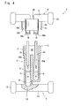
- Fig. 2 is a sectional view of when the liquid chambers of the two-liquid mixing container are closed
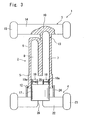
- Fig. 3 is a sectional view of when the liquid chambers are communicated with the mixing chamber.
- the two-liquid mixing container 1 is a container of the so-called type that is discarded after the use of one time, and comprises a plastic container body 2, a lid member 3 provided at an upper portion of the container body 2, and a liquid chamber opening/closing member 4 disposed at a lower portion of the container body 2.
- a circular cylindrical portion 5 is provided at the lower portion of the container body 2.
- the cylindrical portion 5 includes a mixing chamber 20 therein, has its lower end opened, and has a liquid chamber-forming portion 6 at an upper portion thereof.
- the interior of the liquid chamber-forming portion 6, in this embodiment, includes two liquid chambers, i.e., a first liquid chamber 7 and a second liquid chamber 8.
- the liquid chambers 7 and 8 have a circular shape in transverse cross section, and extend in the up-and-down direction of the container body 2.
- the liquid chambers 7 and 8 are forming liquid injection openings 7a and 8a (see Fig. 4 ) on the lower end side facing the mixing chamber 20 (upper end side of the liquid chambers in Fig. 4 ).
- the one or first liquid chamber 7 is longer than the other or second liquid chamber in the up-and-down direction of the container body 2, reaching the upper lid member 3, and its liquid take-out opening 7b is closed by the lid member 3 (see Figs. 6 and 7 ).
- the upper portion of the second liquid chamber 8 is separated by the ceiling wall of the liquid chamber-forming portion 6.
- An annular protuberance 12 is formed on the outer circumference at the lower portion of the container body 2 so as to protrude toward the outer circumferential side of the container body 2.
- the lid member 3 is formed integrally with the container body 2, and includes a lid body 10 and a wing portion 14.
- the wing portion 14 is so formed as to protrude toward the right and left outer sides of the lid body 10.
- the wing portion 14 is coupled to the lid body 10 (at one end), and is provided with support legs 15 coupled to the other end (outer most end) of the wing portion 14.
- the wing portion 14 is a plate member of a square shape, and the upper and lower ends of the support legs 15 are protruding toward both the upper and lower sides beyond the upper portion and the lower portion of the wing portion 14.
- the portion coupling the container body 2 to the lid member 3 is forming a brittle portion 13 by, for example, decreasing the thickness to be smaller than other portions or forming a notch.
- the brittle portion 13 permits the lid member 3 to be easily separated away from the container body 2.
- the liquid chamber opening/closing member 4 can be fitted to the container body 2 from the openings at the lower end of the mixing chamber 20, and is provided with a base portion 17 of a cylindrical shape.
- the base portion 17 is provided with sealing members 18 and 19 that protrude upward from the upper surface thereof.
- the sealing members 18 and 19 are forming sealing members 18a and 19a at their intermediate portions in the up-and-down direction.
- the sealing members 18a and 19a may be formed in a manner that the circumferential surfaces of the sealing members 18 and 19 are annularly protruded outwards integrally therewith, or may be formed by fitting separate members such as O-rings to the circumferential surfaces thereof, or may not be formed if the liquids have large viscosities.
- the base portion 17 has an outer diameter nearly equal to the caliber of the mixing chamber 20 of the container body 2 so as to maintain such a relationship that the outer circumferential surface of the base portion 17 is in close contact with the inner circumferential surface of the mixing chamber 20.
- the base portion may provide sealing relying on such means as annular sealing members 18a, 19a or the O-rings in the same manner as the sealing members 18 and 19.
- the liquid chamber opening/closing member 4 is so formed and fitted as can be slid on the circumferential wall surface of the mixing chamber 20 in both the up-and-down direction and the circumferential direction.
- the sealing members 18 and 19, too, are formed in a size that fits to the liquid injection openings 7a and 8a of the liquid chambers 7 and 8 in close contact thereto so as to maintain air-tightness of the liquid chambers 7 and 8.
- the liquid opening/closing member 4 can slide between an advanced position where it is positioned deeply inside the mixing chamber 20 relative to the container body 2 (see Fig. 2 ) and a reversed position where it is shallowly fitted in the mixing chamber 20 (see Fig. 3 ).
- the sealing members 18 and 19 are fitted into the liquid injection openings 7a and 8a to close the liquid chambers 7 and 8 and to air-tightly separate the liquid chambers 7 and 8.
- the liquid chamber opening/closing member 4 opens the liquid chambers 7 and 8.
- an open space is formed in the upper part of the mixing chamber 20 that had been closed by the base portion 17, and the liquid chambers 7 and 8 are allowed to communicate with each other through the open space in the mixing chamber 20.
- Wing portions 22 are formed at the lower portion of the base portion 17 of the liquid chamber opening/closing member 4 facing each other in the direction of diameter of the base portion 17 and protruding outward.
- the wing portions 22 are coupled at the ends on one side to the base portion 17, and have support legs 23 coupled to the other ends (distal ends) of the wing portions 22.
- the wing portions 22 are plate-like members of a square shape, and the upper and lower ends of the support legs 23 protrude upward and downward beyond the upper portion and the lower portion of the wing portions 22.
- a pair of rod-shaped engaging portions (hook members) 24 are formed extending upward on the upper surfaces of the wing portions 22 at the intermediate portions thereof in the direction in which they extend. Pawls 24a (see Figs.
- a slit 26 is formed between the right and left wing portions 22, 22.
- the slit 26 has a width equal to the thickness of the wing portion 14.
- a positional relationship between the wing portion 14 and the wing portions 22 is such that the wing portion 14 and the wing portions 22 are arranged in the same direction, i.e., arranged on the same plane in a state where the liquid injection openings 7a and 8a are closed by the sealing members 18 and 19.
- the two-liquid mixing container 1 is such that the container body 2, at first, has not been combined with the liquid chamber opening/closing member 4 but the lid member 3 is coupled to the container body 2 integrally together.
- the container body 2 is turned upside down as shown in Fig. 4 .
- an injection jig 28a an adhesive A is introduced into the first liquid chamber 7 through the liquid injection opening 7a of the first liquid chamber 7.
- an adhesive B is introduced into the second liquid chamber 8 through the liquid injection opening 8a of the second liquid chamber 8 so will not to be mixed into the first liquid chamber 7.
- the adhesives A and B that are used have such properties as to commence the chemical reaction right after they are mixed together to undergo solidification.
- the mixing chamber 20 of the container body 2 is combined with the liquid chamber opening/closing member 4.
- the annular protuberance 12 of the container body 2 interferes with the pawls 24a.
- the pawls 24a are forming inclined surfaces 24b at their upper portions and do not become an obstacle.
- the wing portion 14 of the lid member 3 and the wing portions 22 of the liquid chamber opening/closing member 4 are set to be in the same direction (rotational angle); i.e., the sealing members 18, 19 are inserted in the liquid injection openings 7a, 8a, and the liquid chambers 7 and 8 are closed as shown in Fig. 2 .
- the adhesives A and B are separately injected into the liquid chambers 7 and 8, and are not solidified.
- a dentist who is going to treat teeth by using the adhesive contained in the container may now grip the container body 2 by his one hand and may pull the liquid chamber opening/closing member 4 downward of the container body 2 by his other hand. Therefore, the state shown in Fig. 2 is shifted to the state shown in Fig. 3 .
- the pawls 24a of the engaging portions 24 hook to the annular protuberance 12, and the liquid chamber opening/closing member 4 does not escape from the container body 2. This liberates the sealing state of the sealing members 18, 19 and the liquid injection openings 7a, 8a and, besides, an open space is formed in the mixing chamber 20 on the upper surface of the liquid chamber opening/closing member 4 permitting the first liquid chamber 7 and the second liquid chamber 8 to be communicated with each other.
- the liquid chambers 7 and 8 are communicated with the mixing chamber 20 not by pushing the liquid chamber opening/closing member 4 but by pulling it. Therefore, the liquids are prevented from being mixed together by erroneous operation that could be caused by shocks given to the two-liquid mixing container 1 or by strongly gripping it in the course of handing the two-liquid mixing container 1 up to mixing the adhesives together. Because of its structure, further, the liquid chambers 7 and 8 are communicated through without piercing a thin sheet, and no fragment of sheet contaminates into the container. Thus, the adhesive A in the first liquid chamber 7 and the adhesive B in the second liquid chamber 8 are mixed together.
- the sealing members 18 and 19 Since the sealing members 18 and 19 have now been disengaged from the liquid injection openings 7a and 8a, it is allowed to turn the liquid chamber opening/closing member 4 relative to the container body 2 in the circumferential direction (around the axis thereof).
- the sealing members 18 and 19 provided on the upper surface of the liquid chamber opening/closing member 4 serve as stirrer members for favorably mixing the two kinds of adhesives together.
- the lid member 3 is faced upward.
- the container body 2 and the wing portion 14 are turned in the directions opposite to each other to cut the brittle portion 13.
- an adhesive take-out opening 7b is formed in the container body 2.
- the wing portion 14 has a long distance L between the support legs 15 and 15 at both ends thereof to produce a large moment of force and, therefore, the brittle portion 13 can be cut with a small force.
- the wing portion 14 is so turned that its direction is shifted in the circumferential direction by 90 degrees relative to the wing portions 22 of the container body 2. Thereafter, the lid member 3 is brought to just under the liquid chamber opening/closing member 4 and is inserted in the slit 26 formed in the lower portion of the liquid chamber opening/closing member 4.
- the two-liquid mixing container 1 is coupled in the shape of a rocket, and the lower portion of the two-liquid mixing container 1 is formed in a cross shape by the wing portions 22 and the wing portion 14 ( Fig. 7 ).
- the two-liquid mixing container 1 will be placed at a suitable position in a state where the liquid take-out opening 7b of the container body 2 is facing upward; i.e. , the container 1 maintains a stably erected attitude.
- the slit 26 serves as a target position enabling the wing portions 14 and 22 to be easily put together in a cross shape.
- the dentist takes out the adhesive by inserting an end of a rod 30 in the take-out opening 7b of the container body that is placed maintaining stability. The container is prevented from inclining or falling over while the adhesive is being taken out.
- the dentist lets the container body 2 erected on a suitable place, and is allowed to apply the adhesive onto the patient's teeth using both hands.
- the two-liquid mixing container 1 is discarded.
- the container body 2 and the lid member 3 have been coupled integrally together, they do not separate away after discarded.
- the lid member 3 becomes rubbish (unnecessary article) at a moment when the lid member 3 is separated away from the container body 2.
- the lid member 3 can be effectively utilized before it turns into rubbish.
- the wing portions 22 and the wing portion 14 are assembled together in the cross shape, the two-liquid mixing container 1 becomes bulky in both the longitudinal and transverse directions.
- the wing portion 14 and the wing portions 22 are nearly in a planar positional relationship.
- the cylindrical portion 5 of the liquid chamber opening/closing member 4 assumes the greatest thickness as compared to the thicknesses of the wing portions 14 and 22.
- the thickness of the whole package of the containers 1 can be decreased.
- the container is not limited to the dental use only but can be applied to any other containers that require stably erected attitude.
- the container body 2 and the lid member 3 are coupled together through the brittle portion 13 that is so formed as can be broken down.
- the lid member 3, however, may be of the threaded type or the insertion (fit) type.
- the engaging portions 24 formed in a pair on the upper surfaces of the wing portions 22 at intermediate portions thereof in a direction in which they extend, may, further, be formed in a number of three or more in the circumferential direction of the cylindrical portion 5 of the container body 2 maintaining a predetermined distance to more firmly restrict the reversed position of the liquid chamber opening/closing member 4, or may, further, be formed in a manner of surrounding the cylindrical portion 5.
- the liquid chambers 7 and 8 in this embodiment were provided in a number of two, they may be provided in a number of three or more to realize a container for using the adhesive by mixing three of more liquids together.
- the brittle portion 13 was formed on the first liquid chamber 7 and was broken to form the liquid take-out opening 7b.
- the liquid chamber opening/closing member 4 may be removed from the container body 2, and the mixed liquid may be taken out from the side of the mixing chamber 20 (liquid injection openings 7a, 8a).
- the liquid take-out opening becomes the same as the liquid injection openings.
- the engaging portions 24 may be omitted.
Abstract
[Problems] To provide a two-liquid mixing container which prevents two liquids from being mixed together by erroneous operation and does not permit sheet-like contaminants from mixing into the mixed liquid.
[Means for Solution] A container body 2 of the two-liquid mixing container 1 is provided with liquid injection openings 7a, 8a for feeding different treating solutions into a plurality of liquid chambers 7, 8. A liquid chamber opening/closing member 4 is provided with sealing members which are fitted into one end side of the container body 2 and, at an advanced position of having entered into the liquid injection openings, work to close the liquid injection openings 7a, 8a to separately close the liquid chambers 7, 8 and, at a reversed position, work to open the liquid injection openings 7a, 8a permitting the liquid chambers 7, 8 to be communicated with each other.
Description
- This invention relates to a liquid mixing container capable of mixing two or more kinds of liquids together when in use.
- Some dental adhesives are contained in a container for use repetitively a plurality of times while other dental adhesives are contained in a container for use for only one time of treatment. The former container for use repetitively a plurality of times contains the adhesive in an amount enough for the treatment of a number of times; i.e., at the time of use, a lid member is opened, and the adhesive is taken out by only a required amount for the treatment. The latter container contains the adhesive in an amount for only one time of treatment; i . e. , the container in a closed state is opened, and is discarded after the use irrespective of the amount of the adhesive that is remaining.
Dental materials of the type of mixing two liquids have often been used; i.e., two liquid that are separately contained are mixed together just before the use, and are used. The two-liquid mixing container has been frequently used since it obviates the need of injecting the two liquids while measuring them or the need of separately providing the mixing container. - For example, a
patent document 1 discloses a two-liquid mixing container wherein a sheet-like separating member is provided for separating a liquid chamber on the front end side of an injector-shaped cylinder from a liquid chamber of the rear end side, different liquids are contained in the liquid chambers, and a piston is pushed into the cylinder to mix the two liquids together breaking the separating member.
Further, apatent document 2 discloses a two-liquid mixing container wherein a slide member is provided to slide in the container, two liquid chambers are arranged on the slide member in the direction of diameter of the container, and upper ports of the liquid chambers are sealed with sheet-like separating members. The container is provided with unsealing members facing the two upper openings to pierce the separating members simultaneously, and the slide member is moved toward the unsealing members to unseal the liquid chambers by the unsealing members thereby to mix the treating solutions in the two liquid chambers together. -
- Patent document 1:
JP-2005-104534A - Patent document 2:
JP-2004-510540T - So far, as disclosed in the
patent documents patent document 1, in particular, in case the container is fallen by mistake, the piston is pushed due to a shock and the liquids may be mixed together. It may, further, happen that the piston is accidentally pushed in against the will. According to the two-liquid mixing container of thepatent document 2 in which the slide member is contained in the container body, the slide member can be prevented from being pushed in by erroneous operation, but a jig is necessary for pushing in the slide member at the time of mixing the two liquids together.
According to the two-liquid mixing containers of thepatent documents
The present invention was accomplished under the above circumstances, and provides a liquid mixing container which prevents two liquids (or three or more liquids) from being mixed together by erroneous operation and does not permit sheet-like contaminants from mixing into the mixed liquid. - To achieve the above object, the present invention provides a liquid mixing container comprising:
- a container body having a plurality of liquid chambers provided with liquid injection openings, and a mixing chamber for communicating with each of the liquid chambers through the liquid injection openings; and
- a liquid chamber opening/closing member fitted in the mixing chamber of the container body is capable of switching the liquid chambers and the mixing chamber into a communicated state or a closed state;
- wherein the liquid chamber opening/closing member is provided with sealing members which, at an advanced position of having entered into the liquid injection openings, work to close the injection openings to separately close the liquid chambers and, at a backward position, work to open the injection openings permitting the liquid chambers to be communicated with the mixing chamber.
- The mixing container of the present invention is capable of storing liquids having different components by separately packing them in the each liquid chambers. Upon pulling the liquid chamber opening/closing member, the liquids that had been separately packed are mixed together in the mixing chamber in the container exhibiting the following effects in addition to the basic effects of the two-liquid mixing container.
The container body is provided with liquid injection openings for feeding the to-be-mixed liquids to the liquid chambers, and the liquid opening/closing member is provided with the sealing members which are fitted in the mixing chamber on the other end side of the container body. The sealing members, at the advanced position of having entered in the liquid injection openings, work to close the injection openings to separately close the liquid chambers and, at a backward position, work to open the injection openings permitting the liquid chambers to be communicated with each other. Upon pulling the liquid chamber opening/closing member instead of pushing it in, the liquid chambers are permitted to be communicated with the mixing chamber. Therefore, the liquids are prevented from being erroneously mixed together that could result from receiving shocks or strong gripping.
The sealing members of the liquid chamber opening/closing member are convex portions that can be inserted in the liquid injection openings and, at the reversed position, can be turned in the circumferential direction with respect to the container body. Therefore, upon turning the liquid chamber opening/closing member after having been pulled, valve bodies (closing portions) of the liquid chamber opening/closing member play the role of a stirrer enabling the mixed liquid to be stirred and mixed together.
Because of its structure, the liquids have not been separately packed by using a thin sheet. At the time of use, therefore, the liquids are mixed together without piercing through the sheet, and it does not happen that the fragments of sheet are mixed into the container. -
- [
Fig. 1 ] is a disassembled perspective view of a two-liquid mixing container according to an embodiment of the invention. - [
Fig. 2 ] is a sectional view of the two-liquid mixing container when the liquid chambers are closed in a state where the two-liquid mixing container ofFig. 1 is assembled. - [
Fig. 3 ] is a sectional view of the two-liquid mixing container when the two liquid chambers are communicated with each other in the state where the two-liquid mixing container ofFig. 1 is assembled. - [
Fig. 4 ] is a sectional view of the two-liquid mixing container when adhesives are injected into the liquid chambers in a state where the two-liquid mixing container ofFig. 1 is disassembled (in a state of upside down). - [
Fig. 5 ] is a sectional view of the two-liquid mixing container when a lid member is separated away from the two-liquid mixing container ofFig. 1 , and the thus removed lid member is fitted to the main body. - [
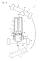
Fig. 6 ] is a sectional view of the two-liquid mixing container when a mixed liquid of adhesives is being taken out from the liquid chambers of the two-liquid mixing container ofFig. 1 . - [
Fig. 7 ] is a perspective view of the two-liquid mixing container when the mixed liquid of adhesives is being taken out from the liquid chambers of the two-liquid mixing container ofFig. 1 . - The container according to an embodiment of the invention will now be described with reference to the drawings.
Fig. 1 is a disassembled view of a two-liquid mixing container that contains adhesives for dental treatment,Fig. 2 is a sectional view of when the liquid chambers of the two-liquid mixing container are closed, andFig. 3 is a sectional view of when the liquid chambers are communicated with the mixing chamber.
The two-liquid mixing container 1 is a container of the so-called type that is discarded after the use of one time, and comprises aplastic container body 2, alid member 3 provided at an upper portion of thecontainer body 2, and a liquid chamber opening/closing member 4 disposed at a lower portion of thecontainer body 2. - A circular
cylindrical portion 5 is provided at the lower portion of thecontainer body 2. Thecylindrical portion 5 includes amixing chamber 20 therein, has its lower end opened, and has a liquid chamber-formingportion 6 at an upper portion thereof. The interior of the liquid chamber-formingportion 6, in this embodiment, includes two liquid chambers, i.e., a firstliquid chamber 7 and a secondliquid chamber 8. Theliquid chambers container body 2. Theliquid chambers liquid injection openings Fig. 4 ) on the lower end side facing the mixing chamber 20 (upper end side of the liquid chambers inFig. 4 ). The one or firstliquid chamber 7 is longer than the other or second liquid chamber in the up-and-down direction of thecontainer body 2, reaching theupper lid member 3, and its liquid take-out opening 7b is closed by the lid member 3 (seeFigs. 6 and7 ). The upper portion of the secondliquid chamber 8 is separated by the ceiling wall of the liquid chamber-formingportion 6.
Anannular protuberance 12 is formed on the outer circumference at the lower portion of thecontainer body 2 so as to protrude toward the outer circumferential side of thecontainer body 2. - The
lid member 3 is formed integrally with thecontainer body 2, and includes alid body 10 and awing portion 14. Thelid body 10, as described above, closes the interior of the firstliquid chamber 7. Thewing portion 14 is so formed as to protrude toward the right and left outer sides of thelid body 10. Thewing portion 14 is coupled to the lid body 10 (at one end), and is provided withsupport legs 15 coupled to the other end (outer most end) of thewing portion 14. Thewing portion 14 is a plate member of a square shape, and the upper and lower ends of thesupport legs 15 are protruding toward both the upper and lower sides beyond the upper portion and the lower portion of thewing portion 14. The portion coupling thecontainer body 2 to thelid member 3 is forming abrittle portion 13 by, for example, decreasing the thickness to be smaller than other portions or forming a notch. Upon turning thelid member 3, thebrittle portion 13 permits thelid member 3 to be easily separated away from thecontainer body 2. - The liquid chamber opening/closing
member 4 can be fitted to thecontainer body 2 from the openings at the lower end of the mixingchamber 20, and is provided with abase portion 17 of a cylindrical shape. Thebase portion 17 is provided with sealingmembers members members members members
Thebase portion 17 has an outer diameter nearly equal to the caliber of the mixingchamber 20 of thecontainer body 2 so as to maintain such a relationship that the outer circumferential surface of thebase portion 17 is in close contact with the inner circumferential surface of the mixingchamber 20. When the adhesives having small viscosities are to be contained, the base portion may provide sealing relying on such means asannular sealing members members
The liquid chamber opening/closingmember 4 is so formed and fitted as can be slid on the circumferential wall surface of the mixingchamber 20 in both the up-and-down direction and the circumferential direction. The sealingmembers liquid injection openings liquid chambers liquid chambers
The liquid opening/closingmember 4 can slide between an advanced position where it is positioned deeply inside the mixingchamber 20 relative to the container body 2 (seeFig. 2 ) and a reversed position where it is shallowly fitted in the mixing chamber 20 (seeFig. 3 ). When the liquid chamber opening/closingmember 4 is at the advanced position as shown inFig. 2 , the sealingmembers liquid injection openings liquid chambers liquid chambers Fig. 3 , the liquid chamber opening/closingmember 4 opens theliquid chambers chamber 20 that had been closed by thebase portion 17, and theliquid chambers chamber 20. -
Wing portions 22 are formed at the lower portion of thebase portion 17 of the liquid chamber opening/closingmember 4 facing each other in the direction of diameter of thebase portion 17 and protruding outward. Thewing portions 22 are coupled at the ends on one side to thebase portion 17, and havesupport legs 23 coupled to the other ends (distal ends) of thewing portions 22. Thewing portions 22 are plate-like members of a square shape, and the upper and lower ends of thesupport legs 23 protrude upward and downward beyond the upper portion and the lower portion of thewing portions 22.
A pair of rod-shaped engaging portions (hook members) 24 are formed extending upward on the upper surfaces of thewing portions 22 at the intermediate portions thereof in the direction in which they extend.Pawls 24a (seeFigs. 1 and4 ) are formed at the distal ends of the engagingportions 24 protruding inward in the direction of diameter.Inclined surfaces 24b facing inward and downward (seeFig. 4 ) are formed at the ends of thepawls 24a. When the liquid chamber opening/closingmember 4 is at its reversed position, thepawls 24 hook to theannular protuberance 12 of thecontainer body 2 to restrict the reversed position of the liquid chamber opening/closingmember 4. The advanced position of the liquid chamber opening/closingmember 4 may be restricted by the engagement of theliquid injection openings members base portion 17 and by the lower end wall surface of theliquid chambers
Aslit 26 is formed between the right andleft wing portions slit 26 has a width equal to the thickness of thewing portion 14. A positional relationship between thewing portion 14 and thewing portions 22 is such that thewing portion 14 and thewing portions 22 are arranged in the same direction, i.e., arranged on the same plane in a state where theliquid injection openings members - The two-
liquid mixing container 1 is such that thecontainer body 2, at first, has not been combined with the liquid chamber opening/closingmember 4 but thelid member 3 is coupled to thecontainer body 2 integrally together. To introduce the adhesives into thecontainer body 2, thecontainer body 2 is turned upside down as shown inFig. 4 . By using aninjection jig 28a, an adhesive A is introduced into the firstliquid chamber 7 through the liquid injection opening 7a of the firstliquid chamber 7. Next, by using aninjection jig 28b, an adhesive B is introduced into the secondliquid chamber 8 through the liquid injection opening 8a of the secondliquid chamber 8 so will not to be mixed into the firstliquid chamber 7. Here, it will be effective if the adhesives A and B that are used have such properties as to commence the chemical reaction right after they are mixed together to undergo solidification.
After the adhesives A and B are injected by predetermined amounts, the mixingchamber 20 of thecontainer body 2 is combined with the liquid chamber opening/closingmember 4. At this moment, theannular protuberance 12 of thecontainer body 2 interferes with thepawls 24a. However, thepawls 24a are forminginclined surfaces 24b at their upper portions and do not become an obstacle. To place theliquid injection openings members wing portion 14 of thelid member 3 and thewing portions 22 of the liquid chamber opening/closingmember 4 are set to be in the same direction (rotational angle); i.e., the sealingmembers liquid injection openings liquid chambers Fig. 2 . Thus, the adhesives A and B are separately injected into theliquid chambers - A dentist who is going to treat teeth by using the adhesive contained in the container may now grip the
container body 2 by his one hand and may pull the liquid chamber opening/closingmember 4 downward of thecontainer body 2 by his other hand. Therefore, the state shown inFig. 2 is shifted to the state shown inFig. 3 . Thepawls 24a of the engagingportions 24 hook to theannular protuberance 12, and the liquid chamber opening/closingmember 4 does not escape from thecontainer body 2. This liberates the sealing state of the sealingmembers liquid injection openings chamber 20 on the upper surface of the liquid chamber opening/closingmember 4 permitting the firstliquid chamber 7 and the secondliquid chamber 8 to be communicated with each other.
Here, theliquid chambers chamber 20 not by pushing the liquid chamber opening/closingmember 4 but by pulling it. Therefore, the liquids are prevented from being mixed together by erroneous operation that could be caused by shocks given to the two-liquid mixing container 1 or by strongly gripping it in the course of handing the two-liquid mixing container 1 up to mixing the adhesives together.
Because of its structure, further, theliquid chambers
Thus, the adhesive A in the firstliquid chamber 7 and the adhesive B in the secondliquid chamber 8 are mixed together. Since the sealingmembers liquid injection openings member 4 relative to thecontainer body 2 in the circumferential direction (around the axis thereof). The sealingmembers member 4 serve as stirrer members for favorably mixing the two kinds of adhesives together. - Referring to
Fig. 5 , to unseal the liquid chambers of the two-liquid mixing container 1, thelid member 3 is faced upward. By gripping thecontainer body 2 or thewing portions 22 by one hand and gripping thewing portion 14 of thelid member 3 by the other hand, thecontainer body 2 and thewing portion 14 are turned in the directions opposite to each other to cut thebrittle portion 13. Upon cutting thebrittle portion 13, an adhesive take-outopening 7b is formed in thecontainer body 2. Here, thewing portion 14 has a long distance L between thesupport legs brittle portion 13 can be cut with a small force.
After thelid member 3 is separated away from thecontainer body 2, thewing portion 14 is so turned that its direction is shifted in the circumferential direction by 90 degrees relative to thewing portions 22 of thecontainer body 2. Thereafter, thelid member 3 is brought to just under the liquid chamber opening/closingmember 4 and is inserted in theslit 26 formed in the lower portion of the liquid chamber opening/closingmember 4. Namely, the two-liquid mixing container 1 is coupled in the shape of a rocket, and the lower portion of the two-liquid mixing container 1 is formed in a cross shape by thewing portions 22 and the wing portion 14 (Fig. 7 ). - The two-
liquid mixing container 1 will be placed at a suitable position in a state where the liquid take-outopening 7b of thecontainer body 2 is facing upward; i.e. , thecontainer 1 maintains a stably erected attitude. In combining thecontainer body 2 with thelid member 3, theslit 26 serves as a target position enabling thewing portions
The dentist takes out the adhesive by inserting an end of arod 30 in the take-outopening 7b of the container body that is placed maintaining stability. The container is prevented from inclining or falling over while the adhesive is being taken out. - Thus, the dentist lets the
container body 2 erected on a suitable place, and is allowed to apply the adhesive onto the patient's teeth using both hands. After the treatment, the two-liquid mixing container 1 is discarded. Here, since thecontainer body 2 and thelid member 3 have been coupled integrally together, they do not separate away after discarded. Usually, thelid member 3 becomes rubbish (unnecessary article) at a moment when thelid member 3 is separated away from thecontainer body 2. According to the invention, however, thelid member 3 can be effectively utilized before it turns into rubbish.
When thewing portions 22 and thewing portion 14 are assembled together in the cross shape, the two-liquid mixing container 1 becomes bulky in both the longitudinal and transverse directions. In a state where the two-liquid mixing container 1 has not been used (Fig. 2 ), however, thewing portion 14 and thewing portions 22 are nearly in a planar positional relationship. In the state where thewing portions cylindrical portion 5 of the liquid chamber opening/closingmember 4 assumes the greatest thickness as compared to the thicknesses of thewing portions liquid mixing containers 1 that are not in use are to be packaged in a box, the thickness of the whole package of thecontainers 1 can be decreased. By overlapping the two-liquid mixing containers 1 in, for example, a laid-down attitude, an increased number of two-liquid mixing containers 1 can be contained in a decreased packaging volume. - Though an embodiment of the present invention was described above, it should be noted that the invention can be, further, modified or varied in a variety of ways without departing from the technical spirit and scope of the invention, as a matter of course.
For example, though the above embodiment has dealt with a dental container for containing dental adhesives, the container is not limited to the dental use only but can be applied to any other containers that require stably erected attitude.
In the above embodiment, further, thecontainer body 2 and thelid member 3 are coupled together through thebrittle portion 13 that is so formed as can be broken down. Thelid member 3, however, may be of the threaded type or the insertion (fit) type.
The engagingportions 24 formed in a pair on the upper surfaces of thewing portions 22 at intermediate portions thereof in a direction in which they extend, may, further, be formed in a number of three or more in the circumferential direction of thecylindrical portion 5 of thecontainer body 2 maintaining a predetermined distance to more firmly restrict the reversed position of the liquid chamber opening/closingmember 4, or may, further, be formed in a manner of surrounding thecylindrical portion 5. - Though the
liquid chambers
In the above embodiment, further, thebrittle portion 13 was formed on the firstliquid chamber 7 and was broken to form the liquid take-outopening 7b. Instead of forming the liquid take-outopening 7b, however, the liquid chamber opening/closingmember 4 may be removed from thecontainer body 2, and the mixed liquid may be taken out from the side of the mixing chamber 20 (liquid injection openings portions 24 may be omitted. -
- 1
- two-liquid mixing container
- 2
- container body
- 3
- lid member
- 4
- liquid chamber opening/closing member
- 5
- cylindrical portion
- 6
- liquid chamber-forming portion
- 7
- first liquid chamber
- 7a, 8a
- liquid injection openings
- 7b
- liquid take-out opening
- 8
- second liquid chamber
- 10
- lid body
- 12
- annular protuberance
- 13
- brittle portion
- 14, 22
- wing portions
- 15
- support legs (second support portions)
- 17
- base portion
- 18, 19
- sealing members
- 20
- mixing chamber
- 23
- support legs (second support portions)
- 24
- engaging portions (hooking members)
- 24a
- pawls
- 24b
- inclined surfaces
The liquid chamber opening/closing member of the liquid mixing container at the backward position can be turned in the circumferential direction with respect to the container body.
The container body of the liquid mixing container may have a liquid take-out opening formed With the liquid chamber on the side opposite to the position where the liquid injection opening is provided, and may be provided with a lid member for closing the liquid take-out opening.
The liquid mixing container may be such that the liquid chamber opening/closing member is provided with shaft-like first support portions for supporting the container body, the lid member is provided with shaft-like second support portions for supporting the container body and, after the lid member is detached from the container body, the first support portions and the second support portions are assembled together in a cross shape to support the container body in an erected attitude with the liquid take-out opening of the container body facing upward.
Claims (5)
- A liquid mixing container comprising:a container body having a plurality of liquid chambers provided with liquid injection openings at the ends on one side, and a mixing chamber for communicating the liquid chambers with each other through said liquid injection openings; anda liquid chamber opening/closing member fitted in the mixing chamber of said container body is capable of switching the liquid chambers and the mixing chamber into a closed state or a communicated state;wherein said liquid chamber opening/closing member is provided with sealing members which, at an advanced position of having entered into said liquid injection openings, work to close said injection openings to separately close said liquid chambers and, at a backward position, work to open said injection openings permitting said liquid chambers to be communicated with the mixing chamber.
- The liquid mixing container according to claim 1, wherein the sealing members of said liquid chamber opening/closing member are convex portions capable of being inserted in said liquid injection openings.
- The liquid mixing container according to claim 2, wherein said liquid chamber opening/closing member at the reversed position can be turned in the circumferential direction with respect to said container body.
- The liquid mixing container according to any one of claims 1 to 3, wherein said container body has a liquid take-out opening formed in the liquid chamber on the side opposite to the position where said liquid injection opening is provided, and is provided with a lid member for closing said liquid take-out opening.
- The liquid mixing container according to claim 4, wherein said liquid chamber opening/closing member is provided with shaft-like first support portions for supporting said container body, said lid member is provided with shaft-like second support portions for supporting said container body and, after the lid member is detached from said container body, said first support portions and said second support portions are assembled together in a cross shape to support said container body in an erected attitude with said liquid take-out opening of said container body facing upward.
Applications Claiming Priority (2)
| Application Number | Priority Date | Filing Date | Title |
|---|---|---|---|
| JP2009206226A JP5467822B2 (en) | 2009-09-07 | 2009-09-07 | Liquid mixing container |
| PCT/JP2010/064091 WO2011027674A1 (en) | 2009-09-07 | 2010-08-20 | Liquid mixing container |
Publications (1)
| Publication Number | Publication Date |
|---|---|
| EP2476632A1 true EP2476632A1 (en) | 2012-07-18 |
Family
ID=43649213
Family Applications (1)
| Application Number | Title | Priority Date | Filing Date |
|---|---|---|---|
| EP10813623A Withdrawn EP2476632A1 (en) | 2009-09-07 | 2010-08-20 | Liquid mixing container |
Country Status (5)
| Country | Link |
|---|---|
| US (1) | US20120160718A1 (en) |
| EP (1) | EP2476632A1 (en) |
| JP (1) | JP5467822B2 (en) |
| CN (1) | CN102482025A (en) |
| WO (1) | WO2011027674A1 (en) |
Families Citing this family (1)
| Publication number | Priority date | Publication date | Assignee | Title |
|---|---|---|---|---|
| US10729850B1 (en) | 2019-11-15 | 2020-08-04 | King Saud University | Modular dental material dispenser |
Family Cites Families (19)
| Publication number | Priority date | Publication date | Assignee | Title |
|---|---|---|---|---|
| US3696919A (en) * | 1970-10-08 | 1972-10-10 | Colgate Palmolive Co | Double container with mixing means |
| JPS537952Y2 (en) * | 1971-05-20 | 1978-02-28 | ||
| US3856138A (en) * | 1973-05-31 | 1974-12-24 | Shionogi & Co | Compartmentalized container |
| US4410085A (en) * | 1982-05-03 | 1983-10-18 | Manufacture Lyonnaise De Bouchage | Drinking goblet enabling two doses of constituents to be mixed just before consumption |
| US4550825A (en) * | 1983-07-27 | 1985-11-05 | The West Company | Multicompartment medicament container |
| JPH0533153Y2 (en) * | 1990-07-05 | 1993-08-24 | ||
| JPH0435575U (en) * | 1990-07-18 | 1992-03-25 | ||
| JPH11130156A (en) * | 1997-10-27 | 1999-05-18 | Shiseido Co Ltd | Double-pack mixing container, and double-pack mixing container connector |
| BR0114608A (en) | 2000-10-13 | 2003-12-23 | Dentsply Int Inc | Multi-component blending, storage and distribution packaging |
| JP4357920B2 (en) | 2003-09-30 | 2009-11-04 | 株式会社ジーシー | Two-component mixing container |
| KR100622282B1 (en) * | 2004-08-19 | 2006-09-19 | 오종석 | Medicine Bottle for Injection |
| EP1728560A1 (en) * | 2005-06-03 | 2006-12-06 | 3M Innovative Properties Company | System for storing and dispensing of a substance |
| EP2013112A4 (en) * | 2006-03-20 | 2010-06-16 | Nordson Corp | Propellant actuated dual fluid cartridge |
| DE602008002613D1 (en) * | 2007-03-08 | 2010-11-04 | Tokuyama Dental Corp | container |
| JP5110920B2 (en) * | 2007-03-08 | 2012-12-26 | 株式会社トクヤマデンタル | container |
| JP4944671B2 (en) * | 2007-05-22 | 2012-06-06 | 株式会社トクヤマデンタル | container |
| US8104611B2 (en) * | 2007-08-09 | 2012-01-31 | Helou Jr Elie | Mixing container and method of filling |
| US20090211927A1 (en) * | 2008-02-21 | 2009-08-27 | Wu Kuo Cheng | Container structure for contain different beverages |
| US8083056B1 (en) * | 2011-03-14 | 2011-12-27 | Kuo Chen Wu | Container |
-
2009
- 2009-09-07 JP JP2009206226A patent/JP5467822B2/en active Active
-
2010
- 2010-08-20 WO PCT/JP2010/064091 patent/WO2011027674A1/en active Application Filing
- 2010-08-20 US US13/394,260 patent/US20120160718A1/en not_active Abandoned
- 2010-08-20 EP EP10813623A patent/EP2476632A1/en not_active Withdrawn
- 2010-08-20 CN CN2010800392455A patent/CN102482025A/en active Pending
Non-Patent Citations (1)
| Title |
|---|
| See references of WO2011027674A1 * |
Also Published As
| Publication number | Publication date |
|---|---|
| US20120160718A1 (en) | 2012-06-28 |
| JP5467822B2 (en) | 2014-04-09 |
| CN102482025A (en) | 2012-05-30 |
| WO2011027674A1 (en) | 2011-03-10 |
| JP2011057238A (en) | 2011-03-24 |
Similar Documents
| Publication | Publication Date | Title |
|---|---|---|
| EP2724789B1 (en) | Fluid dispensing assemblies and methods of dispensing fluids from containers | |
| JP6111205B2 (en) | Lid and container assembly for compounded products | |
| US9131930B2 (en) | Devices for filling a multi-use syringe or single-use syringe | |
| US7951109B2 (en) | Liquid chamber cap with compartment for use with injectables | |
| EP2377772A1 (en) | Additive dispenser/hermetic closure system for containers and/or jars | |
| EP2882400B1 (en) | Reconstitution device | |
| WO2005084135A8 (en) | A cartridge unit for a multi-compartment container assembly | |
| US11266569B2 (en) | Primary packaging for storage and administration of medical and pharmaceutical compounds | |
| CA2572799A1 (en) | A syringe assembly | |
| US4591357A (en) | Container for drug isolation, storage and subsequent mixing | |
| EP2837577A1 (en) | Bottle cap | |
| US20120296309A1 (en) | Mixing tool | |
| US7681762B2 (en) | Device for storing and dispensing fluid substances | |
| EP2476632A1 (en) | Liquid mixing container | |
| JP5309308B2 (en) | Pouring tool | |
| EP2737872A1 (en) | Dental container | |
| JPH04106266U (en) | Container for dropping two-drug mixture | |
| KR200363733Y1 (en) | Mixing lid | |
| KR101921719B1 (en) | Shaker Tumbler with Desorption Storage Space | |
| JP2001080681A (en) | Storage method and mixing container of reactive substance, mixing container of additive substance, auxiliary member used for the mixing container | |
| JP2010222017A (en) | Opening tool | |
| KR20110120177A (en) | Reusable dissimilar material mixing container with lid as a medium | |
| JP2005096862A (en) | Cap having removing member and medicine storage container | |
| KR20040108377A (en) | Cap which is so configured that different material storing portion inside the cap is destroyed by means of separate tool and different material is mixed | |
| KR20170000459U (en) | Portable boring machine |
Legal Events
| Date | Code | Title | Description |
|---|---|---|---|
| PUAI | Public reference made under article 153(3) epc to a published international application that has entered the european phase |
Free format text: ORIGINAL CODE: 0009012 |
|
| 17P | Request for examination filed |
Effective date: 20120227 |
|
| AK | Designated contracting states |
Kind code of ref document: A1 Designated state(s): AL AT BE BG CH CY CZ DE DK EE ES FI FR GB GR HR HU IE IS IT LI LT LU LV MC MK MT NL NO PL PT RO SE SI SK SM TR |
|
| DAX | Request for extension of the european patent (deleted) | ||
| STAA | Information on the status of an ep patent application or granted ep patent |
Free format text: STATUS: THE APPLICATION HAS BEEN WITHDRAWN |
|
| 18W | Application withdrawn |
Effective date: 20130116 |