JP5461884B2 - Imaging device - Google Patents

Imaging device Download PDF

Info

Publication number
JP5461884B2
JP5461884B2 JP2009117101A JP2009117101A JP5461884B2 JP 5461884 B2 JP5461884 B2 JP 5461884B2 JP 2009117101 A JP2009117101 A JP 2009117101A JP 2009117101 A JP2009117101 A JP 2009117101A JP 5461884 B2 JP5461884 B2 JP 5461884B2
Authority
JP
Japan
Prior art keywords
mirror
shutter
cam
lever
gear
Prior art date
Legal status (The legal status is an assumption and is not a legal conclusion. Google has not performed a legal analysis and makes no representation as to the accuracy of the status listed.)
Active
Application number
JP2009117101A
Other languages
Japanese (ja)
Other versions
JP2010266617A5 (en
JP2010266617A (en
Inventor
昌幸 三澤
Current Assignee (The listed assignees may be inaccurate. Google has not performed a legal analysis and makes no representation or warranty as to the accuracy of the list.)
Ricoh Imaging Co Ltd
Original Assignee
Ricoh Imaging Co Ltd
Priority date (The priority date is an assumption and is not a legal conclusion. Google has not performed a legal analysis and makes no representation as to the accuracy of the date listed.)
Filing date
Publication date
Application filed by Ricoh Imaging Co Ltd filed Critical Ricoh Imaging Co Ltd
Priority to JP2009117101A priority Critical patent/JP5461884B2/en
Priority to US12/777,434 priority patent/US8137006B2/en
Priority to CN201010180999.4A priority patent/CN101887209B/en
Priority to DE102010016961.7A priority patent/DE102010016961B4/en
Publication of JP2010266617A publication Critical patent/JP2010266617A/en
Publication of JP2010266617A5 publication Critical patent/JP2010266617A5/ja
Application granted granted Critical
Publication of JP5461884B2 publication Critical patent/JP5461884B2/en
Active legal-status Critical Current
Anticipated expiration legal-status Critical

Links

Images

Classifications

    • GPHYSICS
    • G03PHOTOGRAPHY; CINEMATOGRAPHY; ANALOGOUS TECHNIQUES USING WAVES OTHER THAN OPTICAL WAVES; ELECTROGRAPHY; HOLOGRAPHY
    • G03BAPPARATUS OR ARRANGEMENTS FOR TAKING PHOTOGRAPHS OR FOR PROJECTING OR VIEWING THEM; APPARATUS OR ARRANGEMENTS EMPLOYING ANALOGOUS TECHNIQUES USING WAVES OTHER THAN OPTICAL WAVES; ACCESSORIES THEREFOR
    • G03B19/00Cameras
    • G03B19/02Still-picture cameras
    • G03B19/12Reflex cameras with single objective and a movable reflector or a partly-transmitting mirror
    • HELECTRICITY
    • H04ELECTRIC COMMUNICATION TECHNIQUE
    • H04NPICTORIAL COMMUNICATION, e.g. TELEVISION
    • H04N23/00Cameras or camera modules comprising electronic image sensors; Control thereof
    • H04N23/70Circuitry for compensating brightness variation in the scene
    • H04N23/73Circuitry for compensating brightness variation in the scene by influencing the exposure time
    • HELECTRICITY
    • H04ELECTRIC COMMUNICATION TECHNIQUE
    • H04NPICTORIAL COMMUNICATION, e.g. TELEVISION
    • H04N25/00Circuitry of solid-state image sensors [SSIS]; Control thereof
    • H04N25/50Control of the SSIS exposure
    • H04N25/53Control of the integration time

Description

本発明は撮像装置に関し、特に、光学ファインダで被写体を観察する状態と、イメージセンサによる電子画像を観察するライブビュー状態とを選択可能な撮像装置におけるミラー及びシャッタの駆動制御機構に関する。   The present invention relates to an imaging apparatus, and more particularly to a mirror and shutter drive control mechanism in an imaging apparatus capable of selecting a state in which an object is observed with an optical finder and a live view state in which an electronic image is observed with an image sensor.

デジタル一眼レフカメラでは、光学ファインダによる被写体観察とは別に、イメージセンサで得られる電子画像をモニタ上で観察する、いわゆるライブビューモードを備えたものが知られている。ライブビューモードでは、被写体観察時にクイックリターンミラー(以下、ミラー)が撮影光路上から退避された位置(ミラーアップ状態)に保持されている点が、光学ファインダによる観察状態とは異なる。そのため、ライブビューモードで撮影動作を行う場合は、通常撮影モードとは異なる態様でミラーやシャッタの駆動制御を行う必要がある。   A digital single-lens reflex camera is known to have a so-called live view mode in which an electronic image obtained by an image sensor is observed on a monitor, in addition to subject observation by an optical viewfinder. The live view mode is different from the observation state by the optical viewfinder in that the quick return mirror (hereinafter referred to as a mirror) is held at a position (mirror-up state) retracted from the photographing optical path during subject observation. Therefore, when performing a shooting operation in the live view mode, it is necessary to perform drive control of the mirror and the shutter in a manner different from the normal shooting mode.

特許文献1の一眼レフカメラでは、一つのモータによって駆動されるカムギヤの回転によってミラーの昇降動作、シャッタチャージ動作、絞りの制御などを行っている。特許文献1はフィルムカメラを対象としたものであるが、このカムギヤによる駆動機構を用いてデジタルカメラのライブビューにおける撮影シーケンスを構築することが可能である。   In the single-lens reflex camera of Patent Document 1, the raising / lowering operation of the mirror, the shutter charging operation, the diaphragm control, and the like are performed by the rotation of the cam gear driven by one motor. Patent Document 1 is directed to a film camera, but it is possible to construct a shooting sequence in a live view of a digital camera using this cam gear drive mechanism.

非特許文献1の一眼レフカメラでは、撮影に用いるイメージセンサとは別に、ファインダ光学系の中にライブビュー専用のイメージセンサを設け、ライブビューモードでのミラーアップは行わず、このファインダ内の専用センサを用いて擬似的にライブビューを行っている。   In the single-lens reflex camera of Non-Patent Document 1, an image sensor dedicated for live view is provided in the finder optical system separately from the image sensor used for shooting, and mirror-up is not performed in the live view mode. A live view is simulated using a sensor.

また、非特許文献2のように、ミラー駆動機構とシャッタ駆動機構にそれぞれ個別の駆動源を備えた一眼レフカメラでは、ライブビューモードでの撮影動作は、ミラー駆動機構によってミラーアップ状態を維持させつつ、シャッタ駆動機構によってシャッタチャージを行わせることができ、ミラーとシャッタを共通の駆動源で駆動させるタイプに比べて制御が容易である。   Also, as in Non-Patent Document 2, in a single-lens reflex camera provided with separate drive sources for the mirror drive mechanism and the shutter drive mechanism, the shooting operation in the live view mode is maintained in the mirror up state by the mirror drive mechanism. On the other hand, shutter charging can be performed by the shutter drive mechanism, and control is easier compared to the type in which the mirror and the shutter are driven by a common drive source.

特許第3153482号Japanese Patent No. 3153482

「アサヒカメラ 2008年8月号」、朝日新聞出版、2008年、202頁及び203頁“Asahi Camera August 2008 issue”, Asahi Shimbun Publishing, 2008, pages 202 and 203 「アサヒカメラ 2008年1月号」、朝日新聞出版、2008年、230頁及び231頁“Asahi Camera January 2008”, Asahi Shimbun Publishing, 2008, pages 230 and 231

特許文献1のように一つの駆動源でミラー駆動、シャッタチャージ、絞り制御を行うタイプでは、駆動源の共用化により駆動機構の小型化及び軽量化を図ることができる。その一方、このタイプの駆動機構で通常の撮影シーケンスを司る機構をそのまま使用してライブビューモードにおける撮影シーケンスを構築した場合、ライブビューモードでの撮影動作のたびに、シャッタ作動以外の不要な動作、例えばミラーのアップダウン、絞りの開放動作なども行われてしまうことが判明した。ライブビューモードでミラーがアップダウンするとモニタ上の画像が一瞬ブラックアウトするため、使用感に影響する。また、駆動機構における負荷軽減や動作速度向上といった観点からも、このような不要な機械的動作は生じないようにすることが望ましい。   In the type in which mirror drive, shutter charge, and aperture control are performed with a single drive source as in Patent Document 1, the drive mechanism can be reduced in size and weight by sharing the drive source. On the other hand, when a shooting sequence in the live view mode is built using the mechanism that controls the normal shooting sequence with this type of drive mechanism, an unnecessary operation other than the shutter operation is required for each shooting operation in the live view mode. For example, it has been found that mirror up / down and aperture opening operations are also performed. When the mirror is moved up and down in live view mode, the image on the monitor is blacked out for a moment, which affects the feeling of use. Also, from the viewpoint of reducing the load on the drive mechanism and improving the operation speed, it is desirable to prevent such unnecessary mechanical operation from occurring.

非特許文献1の一眼レフカメラでは、撮影時に用いるイメージセンサとは別のイメージセンサによる電子画像を観察するので、厳密な意味でのライブビューでなく、モニタで観察した画像と撮影した画像の不一致が生じるおそれがある。また、ファインダ内にイメージセンサ用の搭載スペースを要するためカメラの小型化の妨げとなり、製造コストも高くなる点が問題である。   Since the single-lens reflex camera of Non-Patent Document 1 observes an electronic image by an image sensor different from the image sensor used at the time of photographing, it is not a live view in a strict sense, but the image observed on the monitor does not match May occur. In addition, since a mounting space for the image sensor is required in the finder, it is a problem that the size of the camera is hindered and the manufacturing cost is increased.

非特許文献2の構成を用いた場合、ライブビューモードの撮影動作におけるミラーのアップダウンは生じないようにすることができるが、ミラー駆動系とシャッタ駆動系のそれぞれに独立した駆動源や機構を設けるため、カメラが大型化し、重量も増加する。また、製造コストも高くなる。   When the configuration of Non-Patent Document 2 is used, it is possible to prevent the mirror from moving up and down in the shooting operation in the live view mode. However, independent drive sources and mechanisms are provided for the mirror drive system and the shutter drive system, respectively. The provision of the camera increases the size and weight of the camera. In addition, the manufacturing cost increases.

本発明は以上の問題点に鑑みてなされたものであり、ミラーを撮影光路上から退避させて被写体観察を行うライブビューモードにおいてミラーの不要な動作を伴わずに撮影動作を行うことができ、かつその駆動機構を小型軽量に構成可能な撮像装置を提供することを目的とする。   The present invention has been made in view of the above problems, and can perform a shooting operation without unnecessary operation of the mirror in a live view mode in which the subject is observed by retracting the mirror from the shooting optical path. And it aims at providing the imaging device which can comprise the drive mechanism small and lightweight.

本発明の撮像装置は、撮像光学系からの光を反射させてファインダ光学系に導くファインダ観察位置と、撮像光学系からの光を反射せずにイメージセンサに入射させる退避位置に揺動可能なミラー;イメージセンサへの光の入射を遮断及び許容するシャッタ;一の方向と他の方向に回転可能なモータ;モータに連動したとき、ミラーの揺動動作とシャッタのチャージ動作を行わせる第1の作動機構部;モータに連動したとき、ミラーの揺動動作を行わせずにシャッタのチャージ動作を行わせる第2の作動機構部;及び、単一の切替ギヤを備え、モータを一の方向に回転させたとき、切替ギヤから第1の作動機構部にモータ駆動力を伝達し、モータを他の方向に回転させたとき、切替ギヤから第2の作動機構部にモータ駆動力を伝達する駆動力伝達切替手段;を備えたことを特徴としている。
本発明はまた、ミラー及びシャッタを駆動して撮像する第1の撮像モードと、ミラーとシャッタのうちシャッタのみ駆動して撮像可能な第2の撮像モードを備えた撮像装置において、ミラーは撮像光学系からの光を反射させてファインダに導くファインダ観察位置と、撮像光学系からの光をイメージセンサに入射させる退避位置とに揺動可能なクイックリターンミラーであり、第1の撮像モードで撮像駆動を行う第1の作動機構部と、第2の撮像モードで撮像駆動を行う第2の作動機構部と、第1の作動機構部と第2の撮像機構部を選択的に切替駆動可能な単一の切替ギヤと、切替ギヤに回転力を伝達するモータとを有し、第2の撮像モードで撮像を行うとき、ミラーが退避位置に一度揺動した後はシャッタ駆動のみで撮像可能であることを特徴としている。
The image pickup apparatus of the present invention can swing between a viewfinder observation position that reflects light from the image pickup optical system and guides the light to the viewfinder optical system, and a retreat position that enters the image sensor without reflecting light from the image pickup optical system. A mirror; a shutter that blocks and allows the incidence of light on the image sensor; a motor that can rotate in one direction and the other; a first that causes the mirror to swing and charge the shutter when linked to the motor. A second actuating mechanism unit that performs a shutter charging operation without oscillating the mirror when interlocked with the motor; and a single switching gear; When the motor is rotated, the motor driving force is transmitted from the switching gear to the first operating mechanism, and when the motor is rotated in the other direction, the motor driving force is transmitted from the switching gear to the second operating mechanism. Driving force It is characterized by having a; reach switching means.
The present invention also provides an imaging apparatus including a first imaging mode for imaging by driving a mirror and a shutter, and a second imaging mode capable of imaging by driving only the shutter among the mirror and the shutter. A quick return mirror that can swing between a viewfinder observation position that reflects light from the system and guides it to the viewfinder, and a retreat position that allows light from the imaging optical system to enter the image sensor, and drives imaging in the first imaging mode. A first actuating mechanism that performs imaging, a second actuating mechanism that performs imaging driving in the second imaging mode, and a single actuator that can selectively drive the first actuating mechanism and the second imaging mechanism. Having one switching gear and a motor that transmits the rotational force to the switching gear, and when imaging in the second imaging mode, imaging can be performed only by shutter drive after the mirror has once swung to the retracted position. That It is a symptom.

本発明の撮像装置は、好ましくは次のように構成するとよい。まず、ミラーの駆動手段として、該ミラーをファインダ観察位置に保持させるミラーダウン位置と、該ミラーを退避位置に保持させるミラーアップ位置の間で揺動可能なミラー駆動レバーを備え、シャッタチャージの制御手段として、シャッタの走行を許容するチャージ解除位置と、走行後のシャッタのチャージ動作を行わせるチャージ位置の間で揺動可能なシャッタチャージレバーを備える。第1の作動機構部は、ミラー駆動レバーの揺動を制御するミラー制御カムと、シャッタチャージレバーの揺動を制御する第1のシャッタ制御カムが形成された第1のカムギヤを備える。また、第2の作動機構部は、シャッタチャージレバーの揺動を制御する第2のシャッタ制御カムが形成された第2のカムギヤを備える。そして、駆動力伝達切替手段は、モータの一の方向の駆動と他の方向の駆動によって一の方向と他の方向に回転される太陽ギヤと、該太陽ギヤを中心に揺動可能な揺動アームに軸支され太陽ギヤに対して噛合する遊星ギヤとを有する遊星ギヤ機構によって構成され、モータの一の方向の駆動によって遊星ギヤが第1のカムギヤに噛合し、モータの他の方向の駆動によって遊星ギヤが第2のカムギヤに噛合する。遊星ギヤ機構の遊星ギヤが駆動力伝達切替手段の切替ギヤを構成する。このように駆動力伝達切替手段として遊星ギヤ機構を用いる場合、ミラーを支持する固定部材上に、遊星ギヤ機構の揺動アームの両揺動端を規制する揺動規制部を備えることが好ましい。 The imaging apparatus of the present invention is preferably configured as follows. First, as a mirror drive means, a mirror drive lever that can swing between a mirror down position for holding the mirror in the viewfinder observation position and a mirror up position for holding the mirror in the retracted position is provided to control shutter charge. As a means, a shutter charge lever that can swing between a charge release position that allows the shutter to travel and a charge position that performs the shutter charging operation after the travel is provided. The first operating mechanism includes a first cam gear on which a mirror control cam that controls the swing of the mirror drive lever and a first shutter control cam that controls the swing of the shutter charge lever are formed. The second operating mechanism section includes a second cam gear on which a second shutter control cam for controlling the swing of the shutter charge lever is formed. The driving force transmission switching means includes a sun gear that is rotated in one direction and another direction by driving in one direction of the motor and driving in the other direction, and swinging that can swing around the sun gear. A planetary gear mechanism having a planetary gear that is pivotally supported by the arm and meshes with the sun gear, and the planetary gear meshes with the first cam gear by driving in one direction of the motor, and the drive in the other direction of the motor As a result, the planetary gear meshes with the second cam gear. The planetary gear of the planetary gear mechanism constitutes a switching gear of the driving force transmission switching means. In this way, when the planetary gear mechanism is used as the driving force transmission switching means, it is preferable that a swing restricting portion for restricting both swing ends of the swing arm of the planetary gear mechanism is provided on the fixing member that supports the mirror.

駆動力伝達切替手段として、以上のような遊星ギヤ機構に代えて、回転軸方向に移動するギヤを有するすべり歯車機構を用いることもできる。この場合、第1のカムギヤと第2のカムギヤは、互いに平行な回転軸によって軸支され、該回転軸方向に位置を異ならせて配置される。そして、駆動力伝達切替手段を構成する切替ギヤとして、第1と第2のカムギヤの回転軸方向に移動可能に支持された軸方向移動ギヤを備え、この軸方向移動ギヤが第1と第2のカムギヤに択一的に噛合される。 Instead of the planetary gear mechanism as described above, a sliding gear mechanism having a gear that moves in the rotation axis direction can be used as the driving force transmission switching means. In this case, the first cam gear and the second cam gear are pivotally supported by rotating shafts parallel to each other, and are arranged at different positions in the rotating shaft direction. As a switching gear constituting the driving force transmission switching means, there is provided an axial movement gear supported so as to be movable in the rotation axis direction of the first and second cam gears. Is selectively engaged with the cam gear.

第1と第2の作動機構部のより具体的な構成として、第1のカムギヤは、モータの一の方向の駆動による原点位置からの一回転動作によって、ミラー駆動レバーをミラーダウン位置からミラーアップ位置へ回動させると共にシャッタチャージレバーをチャージ位置からチャージ解除位置に回動させ、シャッタ走行後にミラー駆動レバーをミラーアップ位置からミラーダウン位置へ回動させると共にシャッタチャージレバーをチャージ解除位置からチャージ位置に回動させるように構成される。一方、第2のカムギヤは、モータの他の方向の駆動による原点位置からの一回転動作によって、シャッタチャージレバーにチャージ解除位置からチャージ位置への往復回動を行わせるように構成される。   As a more specific configuration of the first and second actuating mechanisms, the first cam gear moves the mirror drive lever from the mirror down position to the mirror up by one rotation operation from the origin position by driving in one direction of the motor. And the shutter charge lever from the charge position to the charge release position, and after the shutter travels, the mirror drive lever is rotated from the mirror up position to the mirror down position and the shutter charge lever is moved from the charge release position to the charge position. It is comprised so that it may rotate. On the other hand, the second cam gear is configured to cause the shutter charge lever to reciprocate from the charge release position to the charge position by one rotation operation from the origin position by driving in the other direction of the motor.

以上の第1及び第2のカムギヤと遊星ギヤ機構を備えた構成では、モータの駆動とシャッタの開閉動作を制御する制御回路によって、次のようにライブビューの動作シーケンスを構築するとよい。制御回路は、ライブビュースイッチのオンにより、モータを一の方向に駆動させて第1のカムギヤによってミラー駆動レバーをミラーダウン位置からミラーアップ位置に回動させると共にシャッタチャージレバーをチャージ位置からチャージ解除位置に回動させ、さらにシャッタを開き、撮像光学系からの光が継続してイメージセンサに入射されるライブビュー状態とさせる。制御回路はまた、該ライブビュー状態でのレリーズスイッチのオンにより、一旦シャッタを閉じた後、モータを他の方向に駆動させて第2のカムギヤを一回転させてシャッタチャージレバーのチャージ解除位置からチャージ位置への往復揺動を行わせた後、シャッタを走行させて露光動作を行わせ、さらにモータを他の方向に駆動させて第2のカムギヤを一回転させた後、シャッタを開く。 In the above-described configuration including the first and second cam gears and the planetary gear mechanism, a live view operation sequence may be constructed as follows by a control circuit that controls the driving of the motor and the opening / closing operation of the shutter. When the live view switch is turned on, the control circuit drives the motor in one direction to rotate the mirror drive lever from the mirror down position to the mirror up position by the first cam gear and release the shutter charge lever from the charge position. Then, the shutter is opened, and a live view state in which light from the imaging optical system continues to enter the image sensor is set. The control circuit also closes the shutter once by turning on the release switch in the live view state, and then drives the motor in the other direction to rotate the second cam gear once to release the charge release position of the shutter charge lever. after performing the reciprocating rocking in the charged position, to perform the exposure operation by driving the shutter, after further motor one revolution of the second cam gear is driven in the other direction, the shutter open.

本発明の撮像装置ではさらに、ライブビュー状態でイメージセンサによって得られる被写体の明るさ情報に応じて絞り値を変化させる、第1及び第2の作動機構部とは独立制御される絞り制御機構を備えることができる。   The imaging apparatus according to the present invention further includes an aperture control mechanism that is controlled independently of the first and second operating mechanisms, and changes the aperture value according to the brightness information of the subject obtained by the image sensor in the live view state. Can be provided.

本発明によれば、ファインダ光学系により被写体を観察する通常の撮影モード(第1の撮像モード)では、ミラーの揺動動作とシャッタのチャージ動作を行わせる第1の作動機構部にモータの駆動力が伝達され、ライブビューモード(第2の撮像モード)の撮影動作では、ミラーの揺動動作を行わせずにシャッタのチャージ動作を行わせる第2の作動機構部にモータの駆動力が伝達されるように、モータ駆動力が切り替えて伝達される。そのため、ライブビューモードにおいてミラーの動作を伴わずに撮影動作を行うことができる。また、ミラーの駆動とシャッタチャージ動作を共通のモータで行わせるので、駆動機構を小型かつ軽量に構成することができる。 According to the present invention, in a normal shooting mode (first imaging mode) in which an object is observed with the finder optical system, the motor is driven by the first operating mechanism that performs the swinging operation of the mirror and the charging operation of the shutter. In the shooting operation in the live view mode (second imaging mode) , the driving force of the motor is transmitted to the second operating mechanism that performs the shutter charging operation without performing the mirror swinging operation. Thus, the motor driving force is switched and transmitted. Therefore, it is possible to perform a shooting operation without a mirror operation in the live view mode. Further, since the mirror driving and the shutter charging operation are performed by a common motor, the driving mechanism can be configured to be small and lightweight.

本発明が適用される撮像装置の一例としての一眼レフカメラの光学系の概略を示す図である。It is a figure which shows the outline of the optical system of the single-lens reflex camera as an example of the imaging device to which this invention is applied. 同一眼レフカメラの制御系の要部を示すブロック図である。It is a block diagram which shows the principal part of the control system of a single-lens reflex camera. 同一眼レフカメラのミラーボックス側部に設けられるミラー・シャッタ駆動機構を、一部を断面としてカメラ前方から見た図である。It is the figure which looked at the mirror shutter drive mechanism provided in the mirror box side part of a single-lens reflex camera from the camera front partly in cross section. 同ミラー・シャッタ駆動機構を、一部を断面としてカメラ後方から見た図である。It is the figure which looked at the mirror shutter drive mechanism from the camera back partly with a cross section. ミラーが撮影光路上の下降位置(ファインダ観察位置)に保持されかつシャッタチャージが完了した、通常撮影シーケンスの初期状態におけるミラー・シャッタ駆動機構の側面図である。FIG. 6 is a side view of the mirror / shutter drive mechanism in an initial state of a normal photographing sequence in which the mirror is held at a lowered position (finder observation position) on the photographing optical path and shutter charging is completed. ミラーが撮影光路からの退避位置に保持され、かつシャッタチャージレバーがチャージ解除位置に保持された露光可能状態におけるミラー・シャッタ駆動機構の側面図である。FIG. 6 is a side view of the mirror / shutter drive mechanism in an exposure enabled state in which the mirror is held at the retracted position from the photographing optical path and the shutter charge lever is held at the charge release position. ライブビューモードでの撮影動作時に、図6に示す露光可能状態からモータが逆転駆動(他の方向に駆動)されて遊星ギヤ機構によって第2カムギヤへモータ駆動力が伝達されるようになった状態のミラー・シャッタ駆動機構を示す側面図である。6 is a state in which the motor is reversely driven (driven in the other direction) from the exposure possible state shown in FIG. 6 during the shooting operation in the live view mode, and the motor driving force is transmitted to the second cam gear by the planetary gear mechanism. It is a side view which shows the mirror shutter drive mechanism. 図7の状態から第2カムギヤが回転され、シャッタチャージレバーによるチャージ動作が完了した状態のミラー・シャッタ駆動機構を示す側面図である。FIG. 8 is a side view showing the mirror / shutter drive mechanism in a state where the second cam gear is rotated from the state of FIG. 7 and the charging operation by the shutter charge lever is completed. ミラー・シャッタ駆動機構を構成する遊星ギヤ機構により、モータ駆動力が第1カムギヤに伝達される状態を示した側面図である。It is the side view which showed the state in which a motor drive force is transmitted to the 1st cam gear by the planetary gear mechanism which comprises a mirror shutter drive mechanism. 同遊星ギヤ機構により、モータ駆動力が第2カムギヤに伝達される状態を示した側面図である。FIG. 6 is a side view showing a state in which a motor driving force is transmitted to a second cam gear by the planetary gear mechanism. ミラーが規制ピンに当接する下降位置にあり、ミラー駆動レバーがミラーダウン位置に保持されている状態を示す側面図である。FIG. 6 is a side view showing a state where the mirror is in a lowered position where it comes into contact with a regulating pin and the mirror drive lever is held in the mirror down position. 通常撮影モードの動作シーケンスを示すタイミングチャート図である。It is a timing chart figure which shows the operation | movement sequence of normal imaging | photography mode. ライブビューモードの動作シーケンスを示すタイミングチャート図である。It is a timing chart figure which shows the operation | movement sequence of live view mode. ライブビューモードにおける撮影動作シーケンスを示すタイミングチャート図である。It is a timing chart figure which shows the imaging | photography operation | movement sequence in live view mode. 図5の原点位置にあるときの第1カムギヤと、ミラー駆動レバー及びシャッタチャージレバーとの関係を示す側面図である。FIG. 6 is a side view showing the relationship between the first cam gear, the mirror drive lever, and the shutter charge lever at the origin position in FIG. 5. 図6のミラーアップ完了位置にあるときの第1カムギヤと、ミラー駆動レバー及びシャッタチャージレバーとの関係を示す側面図である。It is a side view which shows the relationship between the 1st cam gear when it exists in the mirror up completion position of FIG. 6, a mirror drive lever, and a shutter charge lever. 図7の原点位置にあるときの第2カムギヤと、シャッタチャージレバー及びバランサーレバーとの関係を示す側面図である。It is a side view which shows the relationship between the 2nd cam gear when it exists in the origin position of FIG. 7, a shutter charge lever, and a balancer lever. 図8のシャッタチャージ完了位置にあるときの第2カムギヤと、シャッタチャージレバー及びバランサーレバーとの関係を示す側面図である。It is a side view which shows the relationship between the 2nd cam gear when it exists in the shutter charge completion position of FIG. 8, a shutter charge lever, and a balancer lever. 通常撮影シーケンスにおいて、図5の原点位置から第1カムギヤが回転され、第1カムギヤに対してミラー駆動レバーによる負荷トルクが作用し始めた状態での、第1カムギヤに対するミラー駆動レバーとシャッタチャージレバーの力の作用関係を示す概念図である。In the normal photographing sequence, the mirror driving lever and the shutter charge lever for the first cam gear in a state where the first cam gear is rotated from the origin position in FIG. 5 and the load torque by the mirror driving lever starts to act on the first cam gear. It is a conceptual diagram which shows the action | operation relationship of this force. 図19の位置から第1カムギヤが回転され、ミラー制御カムによってミラー駆動レバーをミラーアップ位置方向へ回動させ、かつ第1シャッタ制御カムによってシャッタチャージレバーをチャージ解除位置方向へ回動させている途中の、第1カムギヤに対するミラー駆動レバーとシャッタチャージレバーの力の作用関係を示す概念図である。The first cam gear is rotated from the position of FIG. 19, the mirror drive lever is rotated in the mirror up position direction by the mirror control cam, and the shutter charge lever is rotated in the charge release position direction by the first shutter control cam. It is a conceptual diagram which shows the action | operation relationship of the force of the mirror drive lever and shutter charge lever with respect to the 1st cam gear in the middle. 図20の位置からさらに第1カムギヤが回転され、第1シャッタ制御カムによるシャッタチャージレバーのチャージ解除位置への回動が完了した状態の、第1カムギヤに対するミラー駆動レバーとシャッタチャージレバーの力の作用関係を示す概念図である。When the first cam gear is further rotated from the position of FIG. 20 and the rotation of the shutter charge lever to the charge release position by the first shutter control cam is completed, the force of the mirror drive lever and the shutter charge lever against the first cam gear is It is a conceptual diagram which shows an action relationship. 図6のミラーアップ完了位置から第1カムギヤが回転され、第1カムギヤに対してシャッタチャージレバーによる負荷トルクが作用し始めた状態での、第1カムギヤに対するミラー駆動レバーとシャッタチャージレバーの力の作用関係を示す概念図である。The first cam gear is rotated from the mirror up completion position of FIG. 6 and the load torque by the shutter charge lever starts to act on the first cam gear. It is a conceptual diagram which shows an action relationship. 図22の位置から第1カムギヤが回転され、第1シャッタ制御カムによってシャッタチャージレバーをチャージ位置方向へ回動させ、かつミラー制御カムによってミラー駆動レバーをミラーダウン位置方向へ回動させている途中の、第1カムギヤに対するミラー駆動レバーとシャッタチャージレバーの力の作用関係を示す概念図である。The first cam gear is rotated from the position of FIG. 22, the shutter charge lever is rotated in the charge position direction by the first shutter control cam, and the mirror drive lever is rotated in the mirror down position direction by the mirror control cam. It is a conceptual diagram which shows the effect | action relationship of the force of a mirror drive lever and a shutter charge lever with respect to a 1st cam gear. 図23の位置からさらに第1カムギヤが回転され、ミラー制御カムによるミラー駆動レバーのミラーダウン位置への回動が完了した状態の、第1カムギヤに対するミラー駆動レバーとシャッタチャージレバーの力の作用関係を示す概念図である。The first cam gear is further rotated from the position shown in FIG. 23, and the action relationship between the force of the mirror driving lever and the shutter charge lever on the first cam gear in a state where the mirror control cam completes the rotation of the mirror driving lever to the mirror down position. FIG. ライブビューモードでの撮影シーケンスにおいて、図7の原点位置から第2カムギヤが回転され、第2カムギヤに対してシャッタチャージレバーによる負荷トルクが作用し始めた状態での、第2カムギヤに対するシャッタチャージレバーとバランサーレバーの力の作用を示す概念図である。In the shooting sequence in the live view mode, the shutter charge lever for the second cam gear in a state where the second cam gear is rotated from the origin position of FIG. 7 and the load torque by the shutter charge lever starts to act on the second cam gear. It is a conceptual diagram which shows the effect | action of the force of a balancer lever. 図25の位置から第2カムギヤが回転され、第2シャッタ制御カムによってシャッタチャージレバーをチャージ位置方向へ回動させている途中の、第2カムギヤに対するシャッタチャージレバーとバランサーレバーの力の作用関係を示す概念図である。The second cam gear is rotated from the position shown in FIG. 25, and the action relationship between the force of the shutter charge lever and the balancer lever with respect to the second cam gear during the rotation of the shutter charge lever toward the charge position by the second shutter control cam is shown. FIG. 図26の位置からさらに第2カムギヤが回転され、第2シャッタ制御カムに対するバランサーレバーからのアシストトルクが解除された状態の、第2カムギヤに対するシャッタチャージレバーとバランサーレバーの力の作用関係を示す概念図である。The concept showing the operational relationship between the force of the shutter charge lever and the balancer lever on the second cam gear when the second cam gear is further rotated from the position of FIG. 26 and the assist torque from the balancer lever to the second shutter control cam is released. FIG. ライブビューモードでの撮影シーケンスにおいて、図8のシャッタチャージ完了位置から第2カムギヤが回転され、第2カムギヤに対してバランサーレバーによる負荷トルクが作用し始めた状態での、第2カムギヤに対するシャッタチャージレバーとバランサーレバーの力の作用を示す概念図である。In the shooting sequence in the live view mode, when the second cam gear is rotated from the shutter charge completion position in FIG. 8 and the load torque by the balancer lever starts to act on the second cam gear, the shutter charge for the second cam gear is started. It is a conceptual diagram which shows the effect | action of the force of a lever and a balancer lever. 図28の位置から第2カムギヤが回転され、第2シャッタ制御カムによってシャッタチャージレバーをチャージ解除位置方向へ回動させている途中の、第2カムギヤに対するシャッタチャージレバーとバランサーレバーの力の作用関係を示す概念図である。The second cam gear is rotated from the position of FIG. 28, and the action relationship between the force of the shutter charge lever and the balancer lever with respect to the second cam gear is in the middle of rotating the shutter charge lever toward the charge release position by the second shutter control cam. FIG. 図29の位置からさらに第2カムギヤが回転され、第2シャッタ制御カムによるシャッタチャージレバーのチャージ解除位置への回動が完了した状態の、第2カムギヤに対するシャッタチャージレバーとバランサーレバーの力の作用関係を示す概念図である。The action of the force of the shutter charge lever and the balancer lever on the second cam gear when the second cam gear is further rotated from the position of FIG. 29 and the rotation of the shutter charge lever to the charge release position by the second shutter control cam is completed. It is a conceptual diagram which shows a relationship. 第1カムギヤが原点位置から一回転するときの、ミラー駆動レバーとシャッタチャージレバーによる力の作用関係を示すグラフ図である。It is a graph which shows the action | operation relationship of the force by a mirror drive lever and a shutter charge lever when a 1st cam gear makes one rotation from the origin position. 第2カムギヤが原点位置から一回転するときの、シャッタチャージレバーとバランサーレバーによる力の作用関係を示すグラフ図である。It is a graph which shows the action | operation relationship of the force by a shutter charge lever and a balancer lever when a 2nd cam gear makes one rotation from an origin position. モータ駆動力を2つのカムギヤに択一的に伝達する駆動力伝達切替手段を、すべり歯車機構によって構成した別の実施形態を示す概念図である。It is a conceptual diagram which shows another embodiment which comprised the driving force transmission switching means which alternatively transmits a motor driving force to two cam gears with the sliding gear mechanism. 図33のすべり歯車機構を各ギヤの側方から見た図である。It is the figure which looked at the sliding gear mechanism of FIG. 33 from the side of each gear.

図1に示すデジタル一眼レフカメラ(以下、カメラ)10は、本発明を適用した撮像装置の一実施形態である。カメラ10は、カメラボディ11の前面にレンズ鏡筒12を着脱させるレンズマウントを有し、その内方にミラーボックス(固定部材)13が設けられている。ミラーボックス13内には、ミラーシートヒンジ14xを軸として揺動可能なクイックリターンミラー(以下、ミラー)14が支持されている。ミラー14の後方にはフォーカルプレーンシャッタ(以下、シャッタ)15が設けられ、シャッタ15の後方にはイメージセンサ16が設けられている。ミラー14は、図1の実線や図5に示すように、レンズ鏡筒12内の撮影レンズ(撮像光学系)12aからイメージセンサ16に至る撮影光路上に進出する下降位置(ファインダ観察位置)と、図1の二点鎖線や図6ないし図8に示すように、この撮影光路から上方に退避した上方退避位置の間で揺動される。ミラー14は、ミラーシート上にミラーを支持した構造になっており、図5ないし図8に表われているのはミラーシート部分である。ミラー14が下降位置にあるときには、該ミラー14からの反射光がファインダ光学系17(ペンタプリズムや接眼レンズなどにより構成される)に入射され、ファインダ窓17aを通して被写体を観察することができる。一方、ミラー14が上方退避位置にあるときには、撮影レンズ12aからの光はミラー14で反射されずにシャッタ15側に進み、シャッタ15を開くことでイメージセンサ16の受光面上に光を入射させることができる。カメラボディ11の後面に設けたLCDモニタ18には、イメージセンサ16により得られる被写体の電子画像や、電子画像以外の各種の情報を表示することができる。   A digital single-lens reflex camera (hereinafter referred to as a camera) 10 shown in FIG. 1 is an embodiment of an imaging apparatus to which the present invention is applied. The camera 10 has a lens mount for attaching and detaching the lens barrel 12 on the front surface of the camera body 11, and a mirror box (fixing member) 13 is provided on the inside thereof. In the mirror box 13, a quick return mirror (hereinafter referred to as a mirror) 14 that can swing about a mirror sheet hinge 14x is supported. A focal plane shutter (hereinafter referred to as shutter) 15 is provided behind the mirror 14, and an image sensor 16 is provided behind the shutter 15. As shown in the solid line of FIG. 1 and FIG. 5, the mirror 14 has a descending position (finder observation position) that advances on the photographing optical path from the photographing lens (imaging optical system) 12 a in the lens barrel 12 to the image sensor 16. As shown in the two-dot chain line of FIG. 1 and FIGS. 6 to 8, the rocking is performed between the upper retracted position retracted upward from the photographing optical path. The mirror 14 has a structure in which a mirror is supported on a mirror sheet, and what is shown in FIGS. 5 to 8 is a mirror sheet portion. When the mirror 14 is in the lowered position, the reflected light from the mirror 14 enters the finder optical system 17 (configured by a pentaprism, an eyepiece, etc.), and the subject can be observed through the finder window 17a. On the other hand, when the mirror 14 is in the upper retracted position, the light from the photographic lens 12a is not reflected by the mirror 14 but proceeds to the shutter 15 side, and the light is incident on the light receiving surface of the image sensor 16 by opening the shutter 15. be able to. The LCD monitor 18 provided on the rear surface of the camera body 11 can display an electronic image of the subject obtained by the image sensor 16 and various types of information other than the electronic image.

シャッタ15は、イメージセンサ16に対する入射光軸と直交する面内で走行可能な先幕15a(図2)と後幕15b(図2)からなるシャッタ幕を有している。露光動作時には先幕15aと後幕15bが所定の時間差をもって走行し、後述するシャッタチャージ動作により先幕15aと後幕15bが走行前の位置に戻される。シャッタ15の先幕15a及び後幕15bと連係する部材として、シャッタセットレバー51が設けられている。シャッタセットレバー51は不図示の軸を中心として揺動可能に支持されており、図4ないし図8、図15ないし図18、図23ないし図30にそれぞれ示されているのは、シャッタセットレバー51の自由端部である。シャッタセットレバー51は揺動によってこの自由端部の位置を上下方向に変位させ、自由端部が図5や図8に示す下方のシャッタ保持位置にあるとき、先幕15a及び後幕15bの走行を機械的に規制し、図6や図7に示す上方のシャッタ開放位置にあるとき、先幕15a及び後幕15bの走行を許す。シャッタセットレバー51は、セットレバー復元バネ55(図5ないし図8、図15ないし図18、図23ないし図30に概念的に示す)によって、シャッタ開放位置に向けて付勢されている。そして、シャッタ開放位置からシャッタ保持位置へのシャッタセットレバー51の移動により、先幕15aと後幕15bのシャッタチャージが行われる。チャージされた状態の先幕15aと後幕15bはそれぞれ、先幕保持マグネット52(図2)と後幕保持マグネット53(図2)によって保持する(走行を規制する)ことができる。先幕保持マグネット52は、通電されると励磁(オン)されて吸着力が作用して先幕15aを保持し、通電解除されると非励磁(オフ)状態になって先幕15aを走行させる。同様に、後幕保持マグネット53は、通電されると励磁(オン)されて吸着力が作用して後幕15bを保持し、通電解除されると非励磁(オフ)状態になって後幕15bを走行させる。   The shutter 15 has a shutter curtain including a front curtain 15a (FIG. 2) and a rear curtain 15b (FIG. 2) that can run in a plane orthogonal to the incident optical axis with respect to the image sensor 16. During the exposure operation, the front curtain 15a and the rear curtain 15b travel with a predetermined time difference, and the front curtain 15a and the rear curtain 15b are returned to their pre-travel positions by a shutter charge operation described later. A shutter set lever 51 is provided as a member linked to the front curtain 15 a and the rear curtain 15 b of the shutter 15. The shutter set lever 51 is supported so as to be swingable about a shaft (not shown). FIGS. 4 to 8, 15 to 18, and 23 to 30 respectively show the shutter set lever. 51 is a free end. The shutter set lever 51 swings to displace the position of the free end portion in the vertical direction. When the free end portion is at the lower shutter holding position shown in FIGS. 5 and 8, the front curtain 15a and the rear curtain 15b travel. Is mechanically restricted, and the front curtain 15a and the rear curtain 15b are allowed to travel when the shutter is in the upper shutter open position shown in FIGS. The shutter set lever 51 is biased toward the shutter open position by a set lever restoring spring 55 (conceptually shown in FIGS. 5 to 8, 15 to 18, and 23 to 30). The shutter charge of the front curtain 15a and the rear curtain 15b is performed by the movement of the shutter set lever 51 from the shutter open position to the shutter holding position. The front curtain 15a and the rear curtain 15b in a charged state can be held (restricted travel) by the front curtain holding magnet 52 (FIG. 2) and the rear curtain holding magnet 53 (FIG. 2), respectively. The front curtain holding magnet 52 is energized (turned on) when energized to hold the front curtain 15a by applying an attractive force, and is de-energized (off) when the power is released to run the front curtain 15a. . Similarly, the rear curtain holding magnet 53 is energized (turned on) when energized to hold the rear curtain 15b by applying an attractive force, and is de-energized (off) when the energization is released. To run.

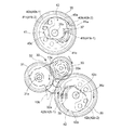
ミラーボックス13の側部にはミラー・シャッタ駆動機構20が設けられている。図3や図4に示すように、ミラーボックス13の側面に対向する位置(図5ないし図8における紙面手前側)にカバー板21が固定され、カバー板21の下端部付近に駆動モータ22が支持されている。駆動モータ22の回転出力軸にはモータピニオン23が設けられ、モータピニオン23の回転は、3つの減速ギヤ24、25及び26からなる減速ギヤ列を介して遊星ギヤ機構(駆動力伝達切替手段)30を構成する太陽ギヤ31に伝達される。図9及び図10に示すように、遊星ギヤ機構30は、太陽ギヤ31の回転軸31xを中心として揺動可能な遊星ギヤアーム32を有し、該遊星ギヤアーム32の先端側に、回転軸31xと平行な回転軸33xによって遊星ギヤ(切替ギヤ)33が回転可能に支持されている。遊星ギヤ33は太陽ギヤ31に対して噛合しており、かつ遊星ギヤ33と遊星ギヤアーム32の間には、遊星フリクションバネ34(図3、図4)によって所定の大きさのフリクション(回転抵抗)が付与されている。 A mirror / shutter drive mechanism 20 is provided on the side of the mirror box 13. As shown in FIGS. 3 and 4, a cover plate 21 is fixed at a position facing the side surface of the mirror box 13 (the front side of the paper in FIGS. 5 to 8), and a drive motor 22 is located near the lower end of the cover plate 21. It is supported. The rotation output shaft of the drive motor 22 is provided with a motor pinion 23, and the rotation of the motor pinion 23 is caused by a planetary gear mechanism (driving force transmission switching means) via a reduction gear train composed of three reduction gears 24, 25 and 26. 30 is transmitted to the sun gear 31 constituting 30. As shown in FIGS. 9 and 10, the planetary gear mechanism 30 includes a planetary gear arm 32 that can swing around the rotation shaft 31 x of the sun gear 31. A planetary gear (switching gear) 33 is rotatably supported by parallel rotation shafts 33x. The planetary gear 33 meshes with the sun gear 31, and a predetermined amount of friction (rotational resistance) is provided between the planetary gear 33 and the planetary gear arm 32 by a planetary friction spring 34 (FIGS. 3 and 4). Is granted.

遊星ギヤ33は、遊星ギヤアーム32の揺動によって第1カムギヤ(第1の作動機構部)35と第2カムギヤ(第2の作動機構部)36に対して択一的に噛合される。遊星ギヤアーム32はサブアーム32aを備え、このサブアーム32aと、ミラーボックス13に形成した揺動制限凸部(揺動規制部)13aとの係合によって、第1カムギヤ35に対する噛合方向への遊星ギヤアーム32の揺動端が決められる。また、サブアーム32aと、ミラーボックス13に形成した揺動制限凸部(揺動規制部)13bとの係合によって、第2カムギヤ36に対する噛合方向への遊星ギヤアーム32の揺動端が決められる。   The planetary gear 33 is selectively meshed with the first cam gear (first operating mechanism) 35 and the second cam gear (second operating mechanism) 36 by the swing of the planetary gear arm 32. The planetary gear arm 32 includes a sub arm 32a, and the planetary gear arm 32 in the meshing direction with respect to the first cam gear 35 is obtained by engaging the sub arm 32a with a swing restricting convex portion (swing restricting portion) 13a formed on the mirror box 13. Is determined. Further, the swinging end of the planetary gear arm 32 in the meshing direction with respect to the second cam gear 36 is determined by the engagement of the sub arm 32 a and the swing restricting convex portion (swing restricting portion) 13 b formed on the mirror box 13.

第1カムギヤ35と第2カムギヤ36はそれぞれ、遊星ギヤ33の回転軸33xと平行な回転軸35x、36xを中心として回転可能にミラーボックス13側面とカバー板21の間に支持されており、その外周部には遊星ギヤ33と噛合可能な周面ギヤが形成されている。第1カムギヤ35と第2カムギヤ36は略同径であり、その周面ギヤの歯数が同一(減速比1:1)である。第1カムギヤ35と第2カムギヤ36にはそれぞれ、カバー板21に向く側の面にコード板ブラシ37、38が設けられており、カバー板21にはコード板ブラシ37、38が摺接するコード板39(図3、図4)が支持されている。コード板39上に形成したパターンとコード板ブラシ37、38の導通関係によって、第1カムギヤ35と第2カムギヤ36のそれぞれにおける特定の回転位置が検出される。この検出される各カムギヤ35、36の回転位置の詳細については後述する。また、第1カムギヤ35には、コード板ブラシ37と反対側の面に、ミラー制御カム40と第1シャッタ制御カム41が形成されている。第2カムギヤ36には、コード板ブラシ38と反対側の面に第2シャッタ制御カム42が形成されている。これらミラー制御カム40と各シャッタ制御カム41、42の詳細形状についても後述する。以上のモータピニオン23から第1カムギヤ35及び第2カムギヤ36に至るまでの各ギヤの回転軸は全て、ミラーシートヒンジ14xの軸線と略平行である。   The first cam gear 35 and the second cam gear 36 are respectively supported between the side surface of the mirror box 13 and the cover plate 21 so as to be rotatable about rotation shafts 35x and 36x parallel to the rotation shaft 33x of the planetary gear 33. A peripheral surface gear that can mesh with the planetary gear 33 is formed on the outer peripheral portion. The first cam gear 35 and the second cam gear 36 have substantially the same diameter, and the number of teeth of the peripheral gear is the same (reduction ratio 1: 1). The first cam gear 35 and the second cam gear 36 are respectively provided with code plate brushes 37 and 38 on the surface facing the cover plate 21, and the code plate brushes 37 and 38 are in sliding contact with the cover plate 21. 39 (FIGS. 3 and 4) is supported. A specific rotational position in each of the first cam gear 35 and the second cam gear 36 is detected by the conductive relationship between the pattern formed on the code plate 39 and the code plate brushes 37 and 38. Details of the detected rotational positions of the cam gears 35 and 36 will be described later. The first cam gear 35 is formed with a mirror control cam 40 and a first shutter control cam 41 on the surface opposite to the code plate brush 37. A second shutter control cam 42 is formed in the second cam gear 36 on the surface opposite to the code plate brush 38. The detailed shapes of the mirror control cam 40 and the shutter control cams 41 and 42 will be described later. All the rotation axes of the gears from the motor pinion 23 to the first cam gear 35 and the second cam gear 36 are substantially parallel to the axis of the mirror seat hinge 14x.

ミラーボックス13側面とカバー板21の間には、ミラーシートヒンジ14xの軸線と略平行な回転軸45xを中心として揺動可能にミラー駆動レバー(第1の作動機構部)45が支持されている。ミラー駆動レバー45は、その先端部付近にミラー押さえ部45aを有し、該ミラー押さえ部45aとミラーアップバネ46によって、ミラー14のミラーシートに設けたミラーシートボス14aを挟んで保持し、回転軸45xを中心としたミラー駆動レバー45の揺動に応じて、ミラー14が上述の下降位置と上方退避位置の間で揺動される。すなわち、ミラー駆動レバー45は、ミラー14を光路上の下降位置に保持させるミラーダウン位置(図5、図15)と、ミラー14を上方退避位置に保持させるミラーアップ位置(図6ないし図8、図16)との間で揺動される。ミラー駆動レバー45は、ミラーダウンバネ47によってミラーダウン位置に向けて回動付勢されている。ミラーダウンバネ47は、ミラー駆動レバー45の回転軸45x回りに配したコイル部と、該コイル部から延出された一対のアームを有するトーションばねからなり、その一方のアームがミラー駆動レバー45のバネ掛け部45cに係合し、他方のアームがミラーボックス13の側面に設けたバネ掛け突起13cに係合している。図5及び図15に示すように、ミラー駆動レバー45がミラーダウン位置にあるとき、ミラー押さえ部45aがミラーシートボス14aを下方に押し込んで、ミラー14を下降位置に保持させる。図3及び図11に示すように、ミラー14の下降位置を定める規制ピン19がミラーボックス13に設けられており、ミラー駆動レバー45は、この規制ピン19によって回動規制されたミラー14のミラーシートボス14aに対してミラー押さえ部45aを当接させることによりミラーダウン位置に保持される。一方、ミラー駆動レバー45に設けたカムフォロア45bに対して第1カムギヤ35のミラー制御カム40が当接可能であり、第1カムギヤ35を図6ないし図8及び図16に示す位置(ミラーアップ完了位置)まで回転させると、ミラー制御カム40によってカムフォロア45bを押し上げて、ミラー駆動レバー45をミラーダウンバネ47の付勢力に抗してミラーアップ位置に保持させることができる。ミラー駆動レバー45がミラーアップ位置にあるとき、ミラーアップバネ46がミラーシートボス14aを押し上げて、ミラー14を上方退避位置に保持させる。このとき、ミラーアップバネ46を若干撓ませることによって、ミラー駆動レバー45の回動量の誤差を吸収してミラー14を確実に上方退避位置に保持させることができるようになっている。また、ミラーボックス13には、このミラー14の上方退避位置でミラーシートの先端部付近が当接する緩衝体(ミラークッション)48が設けられている。   A mirror driving lever (first operating mechanism) 45 is supported between the side surface of the mirror box 13 and the cover plate 21 so as to be swingable about a rotation shaft 45x substantially parallel to the axis of the mirror seat hinge 14x. . The mirror drive lever 45 has a mirror pressing portion 45a near the tip thereof, and is held by the mirror pressing portion 45a and the mirror up spring 46 with the mirror sheet boss 14a provided on the mirror sheet of the mirror 14 being sandwiched and rotated. In response to the swing of the mirror drive lever 45 about the shaft 45x, the mirror 14 is swung between the lowered position and the upper retracted position. That is, the mirror drive lever 45 has a mirror-down position (FIGS. 5 and 15) that holds the mirror 14 in the lowered position on the optical path, and a mirror-up position (FIGS. 6 to 8 that holds the mirror 14 in the upward retracted position). 16). The mirror drive lever 45 is urged to rotate toward the mirror down position by a mirror down spring 47. The mirror down spring 47 includes a torsion spring having a coil portion disposed around the rotation shaft 45x of the mirror drive lever 45 and a pair of arms extending from the coil portion, and one arm of the mirror drive lever 45 is The other arm engages with a spring hooking portion 13 c provided on the side surface of the mirror box 13. As shown in FIGS. 5 and 15, when the mirror drive lever 45 is in the mirror down position, the mirror pressing portion 45a pushes the mirror sheet boss 14a downward to hold the mirror 14 in the lowered position. As shown in FIGS. 3 and 11, a restriction pin 19 that determines the lowering position of the mirror 14 is provided on the mirror box 13, and the mirror drive lever 45 is a mirror of the mirror 14 that is restricted by the restriction pin 19. The mirror pressing portion 45a is brought into contact with the sheet boss 14a to be held at the mirror down position. On the other hand, the mirror control cam 40 of the first cam gear 35 can come into contact with the cam follower 45b provided on the mirror drive lever 45, and the first cam gear 35 is moved to the position shown in FIGS. , The mirror control cam 40 pushes up the cam follower 45b, and the mirror drive lever 45 can be held at the mirror up position against the biasing force of the mirror down spring 47. When the mirror drive lever 45 is in the mirror up position, the mirror up spring 46 pushes up the mirror sheet boss 14a to hold the mirror 14 in the upward retracted position. At this time, by slightly bending the mirror up spring 46, an error in the amount of rotation of the mirror drive lever 45 can be absorbed and the mirror 14 can be reliably held at the upper retracted position. Further, the mirror box 13 is provided with a buffer body (mirror cushion) 48 with which the vicinity of the tip end portion of the mirror sheet abuts at the upper retracted position of the mirror 14.

ミラーボックス13側面とカバー板21の間にはまた、ミラーシートヒンジ14xの軸線と略平行な回転軸50xを中心として揺動可能にシャッタチャージレバー(第1の作動機構部、第2の作動機構部)50が支持されている。シャッタチャージレバー50は、回転軸50xを中心として異なる方向に延出された第1アーム50aと第2アーム50bを有し、第1アーム50aの先端に、シャッタセットレバー51の自由端部に対して当接する先端当接部50cを有している。シャッタチャージレバー50は、先端当接部50cを介してシャッタセットレバー51をシャッタ保持位置に押し込むチャージ位置(図5、図8、図15及び図18)と、該押し込みを解除してシャッタセットレバー51のシャッタ開放位置への移動を許すチャージ解除位置(図6、図7、図16及び図17)との間で揺動可能であり、チャージレバー復元バネ54によってチャージ解除位置に向けて回動付勢されている。チャージレバー復元バネ54は引張バネからなり、その一端部を第1アーム50a上のバネ掛け突起50dに係合させ、他端部をミラーボックス13の側面に設けたバネ掛け突起13dに係合させている。シャッタチャージレバー50は、第1アーム50a上に設けたストッパ部50e(図17、図18参照)をミラーボックス13上の揺動制限凸部13e(図3ないし図8、図15及び図16)に当接させることで、この付勢方向への揺動端(すなわちチャージ解除位置)が定められる。また、第1アーム50a上には第1カムフォロア50fが設けられ、第2アーム50b上には第2カムフォロア50gが設けられている。第1カムフォロア50fと第2カムフォロア50gは、回転軸50xから略等距離に配されている。第1カムフォロア50fに対しては第1カムギヤ35の第1シャッタ制御カム41が当接可能であり、第2カムフォロア50gに対しては第2カムギヤ36の第2シャッタ制御カム42が当接可能である。第1カムギヤ35が図5及び図15に示す位置(原点位置)にあるとき、第1シャッタ制御カム41によって第1カムフォロア50fを押し下げて、チャージレバー復元バネ54の付勢力に抗してシャッタチャージレバー50をチャージ位置に保持させることができる。同様に、第2カムギヤ36を図8及び図18に示す位置(シャッタチャージ完了位置)に回転させることによっても、第2シャッタ制御カム42によって第2カムフォロア50gを押し上げて、チャージレバー復元バネ54の付勢力に抗してシャッタチャージレバー50をチャージ位置に保持させることができる。   A shutter charge lever (first operating mechanism, second operating mechanism) is also provided between the side surface of the mirror box 13 and the cover plate 21 so as to be swingable about a rotation shaft 50x substantially parallel to the axis of the mirror seat hinge 14x. Part) 50 is supported. The shutter charge lever 50 includes a first arm 50a and a second arm 50b that extend in different directions around the rotation shaft 50x. The shutter charge lever 50 has a free end of the shutter set lever 51 at the tip of the first arm 50a. A leading end abutting portion 50c that abuts. The shutter charge lever 50 has a charge position (FIGS. 5, 8, 15, and 18) that pushes the shutter set lever 51 into the shutter holding position via the tip contact portion 50c, and the shutter set lever that releases the push. 51 is swingable between the charge release position (FIGS. 6, 7, 16, and 17) that allows the movement of the shutter 51 to the shutter open position, and is rotated toward the charge release position by the charge lever restoring spring 54. It is energized. The charge lever restoring spring 54 is formed of a tension spring, one end of which is engaged with the spring hooking protrusion 50d on the first arm 50a, and the other end is engaged with the spring hooking protrusion 13d provided on the side surface of the mirror box 13. ing. The shutter charge lever 50 includes a stopper 50e (see FIGS. 17 and 18) provided on the first arm 50a and a swing restricting convex portion 13e on the mirror box 13 (FIGS. 3 to 8, 15, and 16). , The swing end in the biasing direction (that is, the charge release position) is determined. A first cam follower 50f is provided on the first arm 50a, and a second cam follower 50g is provided on the second arm 50b. The first cam follower 50f and the second cam follower 50g are disposed at substantially the same distance from the rotation shaft 50x. The first shutter control cam 41 of the first cam gear 35 can come into contact with the first cam follower 50f, and the second shutter control cam 42 of the second cam gear 36 can come into contact with the second cam follower 50g. is there. When the first cam gear 35 is in the position (origin position) shown in FIGS. 5 and 15, the first cam follower 50 f is pushed down by the first shutter control cam 41, and the shutter charge is resisted against the urging force of the charge lever restoring spring 54. The lever 50 can be held in the charge position. Similarly, by rotating the second cam gear 36 to the position shown in FIGS. 8 and 18 (shutter charge completion position), the second cam follower 50g is pushed up by the second shutter control cam 42 and the charge lever restoring spring 54 is moved. The shutter charge lever 50 can be held at the charge position against the urging force.

ミラーボックス13側面とカバー板21の間にはさらに、ミラーシートヒンジ14xの軸線と略平行な回転軸70xを中心として揺動可能にバランサーレバー70が支持されている。バランサーレバー70は、負荷アーム70aの先端部に、第2シャッタ制御カム42に対して当接可能なカムフォロア70bを備え、このカムフォロア70bを第2シャッタ制御カム42に当接させる方向、すなわち図5ないし図8、図17及び図18の反時計方向へ向けて、バランサーレバー付勢バネ71によって回動付勢されている。バランサーレバー付勢バネ71は、バランサーレバー70の回転軸70x回りに配したコイル部と、該コイル部から延出された一対のアームを有するトーションバネからなっており、その一方のアームを、負荷アーム70aと異なる方向へ延出するバランサーレバー70の規制アーム70cに係合させ、他方のアームを、ミラーボックス13の側面に設けたバネ掛け突起13fに係合させている。規制アーム70cをミラーボックス13の揺動制限凸部13bに対して当接させることにより、バランサーレバー付勢バネ71による付勢方向へのバランサーレバー70の揺動端が定められる。   Further, a balancer lever 70 is supported between the side surface of the mirror box 13 and the cover plate 21 so as to be swingable about a rotation shaft 70x substantially parallel to the axis of the mirror seat hinge 14x. The balancer lever 70 is provided with a cam follower 70b that can be brought into contact with the second shutter control cam 42 at the tip of the load arm 70a, and the direction in which the cam follower 70b comes into contact with the second shutter control cam 42, that is, FIG. In addition, the balancer lever urging spring 71 is urged to rotate counterclockwise in FIGS. 8, 17, and 18. The balancer lever urging spring 71 is composed of a torsion spring having a coil portion disposed around the rotation shaft 70x of the balancer lever 70 and a pair of arms extending from the coil portion. The arm 70 a is engaged with a regulating arm 70 c of a balancer lever 70 extending in a different direction, and the other arm is engaged with a spring hooking protrusion 13 f provided on the side surface of the mirror box 13. By causing the restriction arm 70 c to abut against the swing restricting convex portion 13 b of the mirror box 13, the swing end of the balancer lever 70 in the biasing direction by the balancer lever biasing spring 71 is determined.

カメラ10には、ミラー・シャッタ駆動機構20とは別に、レンズ鏡筒12に設けた絞り12bを駆動制御するための絞り制御機構27(図1に概念的に示す)が設けられている。この絞り制御機構27は、ミラー・シャッタ駆動機構20の駆動モータ22とは別の駆動源によって駆動され、後述するライブビュー中において、イメージセンサ16によって得られる被写体の明るさ情報に応じて絞り12bの大きさ(絞り値)を随時変化させることができる。   In addition to the mirror / shutter driving mechanism 20, the camera 10 is provided with an aperture control mechanism 27 (conceptually shown in FIG. 1) for driving and controlling the aperture 12 b provided in the lens barrel 12. The aperture control mechanism 27 is driven by a drive source different from the drive motor 22 of the mirror / shutter drive mechanism 20, and according to the brightness information of the subject obtained by the image sensor 16 during a live view to be described later. The size (aperture value) can be changed at any time.

図2は、本実施形態におけるカメラ10の制御系の要部を示すブロック図である。なお、カメラ10は、絞り制御機構27による絞り値の設定やシャッタスピードの設定に関わる露出制御装置や、被写体距離情報に基づいて合焦動作を行う自動合焦装置などを備えているが、これらについては図2では省略している。制御回路60は、レリーズスイッチ61、ライブビュースイッチ62、ミラーダウンスイッチ63、ミラーアップスイッチ64、チャージ完了スイッチ65、チャージレバー退避スイッチ66からの信号入力により、内部メモリに格納されたプログラムに従って、駆動モータ22、先幕保持マグネット52及び後幕保持マグネット53の動作を制御する。レリーズスイッチ61は、カメラボディ11の外面に設けたレリーズ釦の押し込み操作によってオンさせることができ、ライブビュースイッチ62は、レリーズ釦とは別にカメラボディ11の外面に設けたライブビュー釦の操作によりオンオフさせることができる。   FIG. 2 is a block diagram showing the main part of the control system of the camera 10 in this embodiment. The camera 10 includes an exposure control device related to setting of an aperture value and shutter speed by the aperture control mechanism 27, an automatic focusing device that performs a focusing operation based on subject distance information, and the like. Is omitted in FIG. The control circuit 60 is driven according to a program stored in the internal memory by inputting signals from the release switch 61, the live view switch 62, the mirror down switch 63, the mirror up switch 64, the charge completion switch 65, and the charge lever retract switch 66. The operation of the motor 22, the front curtain holding magnet 52 and the rear curtain holding magnet 53 is controlled. The release switch 61 can be turned on by pressing a release button provided on the outer surface of the camera body 11, and the live view switch 62 can be operated by operating a live view button provided on the outer surface of the camera body 11 separately from the release button. Can be turned on and off.

ミラーダウンスイッチ63とミラーアップスイッチ64は、コード板ブラシ37とコード板39によって検出される第1カムギヤ35の回転位置情報として入力される。具体的には、第1カムギヤ35が回転して図5及び図15の回転位置(原点位置)に達するとき、ミラーダウンスイッチ63がオンになり、第1カムギヤ35が回転して図6及び図16の回転位置(ミラーアップ完了位置)に達するとき、ミラーアップスイッチ64がオンになる。また、チャージ完了スイッチ65とチャージレバー退避スイッチ66は、コード板ブラシ38とコード板39によって検出される第2カムギヤ36の回転位置情報として入力される。具体的には、第2カムギヤ36が回転して図8及び図18の回転位置(シャッタチャージ完了位置)に達するとき、チャージ完了スイッチ65がオンになり、第2カムギヤ36が回転して図7及び図17の回転位置(原点位置)に達するとき、チャージレバー退避スイッチ66がオンになる。   The mirror down switch 63 and the mirror up switch 64 are input as rotational position information of the first cam gear 35 detected by the code plate brush 37 and the code plate 39. Specifically, when the first cam gear 35 rotates and reaches the rotation position (origin position) of FIGS. 5 and 15, the mirror down switch 63 is turned on, and the first cam gear 35 rotates and rotates as shown in FIGS. When the rotation position 16 (mirror up completion position) is reached, the mirror up switch 64 is turned on. The charge completion switch 65 and the charge lever retract switch 66 are input as rotational position information of the second cam gear 36 detected by the code plate brush 38 and the code plate 39. Specifically, when the second cam gear 36 rotates and reaches the rotation position (shutter charge completion position) of FIGS. 8 and 18, the charge completion switch 65 is turned on, and the second cam gear 36 rotates and rotates as shown in FIG. When the rotation position (origin position) in FIG. 17 is reached, the charge lever retract switch 66 is turned on.

また、制御回路60は画像処理回路を含んでおり、イメージセンサ16の受光面上に結像した被写体像を処理して電子画像データを生成し、メモリカード67などの記録媒体への画像データの記録や、LCDモニタ18での画像表示を行う。   Further, the control circuit 60 includes an image processing circuit, processes the subject image formed on the light receiving surface of the image sensor 16 to generate electronic image data, and outputs the image data to the recording medium such as the memory card 67. Recording and image display on the LCD monitor 18 are performed.

以上のカメラ10の動作について説明する。以下の動作説明で言及されるカムギヤ35、36などの回転方向は、図5ないし図11や図15ないし図30に基づくものである。図5及び図15は、通常撮影モード(第1の撮像モード)におけるミラー・シャッタ駆動機構20の初期状態を示している。初期状態では、第1カムギヤ35のミラー制御カム40によるミラー駆動レバー45(カムフォロア45b)の押し上げが行われておらず、ミラー駆動レバー45がミラーダウンバネ47の付勢力によってミラーダウン位置に保持され、これに応じてミラー14が下降位置に保持されている。また、第1カムギヤ35の第1シャッタ制御カム41によって第1カムフォロア50fが押し下げられ、シャッタチャージレバー50はチャージレバー復元バネ54の付勢力に抗してチャージ位置に保持されている。シャッタチャージレバー50の先端当接部50cに押し下げられて、シャッタセットレバー51はシャッタ保持位置に保持されている。一方、第2カムギヤ36の第2シャッタ制御カム42は第2カムフォロア50gから離れていて、シャッタチャージレバー50の位置制御には関与していない。このときシャッタ15のチャージは完了しており、シャッタセットレバー51がシャッタ保持位置にあることによって先幕15aと後幕15bの走行が機械的に規制されている。先幕保持マグネット52と後幕保持マグネット53はオフされている。以上の初期状態における第1カムギヤ35、第2カムギヤ36の回転位置を原点位置とする。そして、初期状態では、遊星ギヤ機構30は、遊星ギヤ33を第1カムギヤ35側に噛合させた状態にある(図9参照)。 The operation of the camera 10 will be described. The rotation directions of the cam gears 35 and 36 referred to in the following description of the operation are based on FIGS. 5 to 11 and FIGS. 15 to 30. 5 and 15 show the initial state of the mirror / shutter drive mechanism 20 in the normal photographing mode (first imaging mode) . In the initial state, the mirror drive lever 45 (cam follower 45 b) is not pushed up by the mirror control cam 40 of the first cam gear 35, and the mirror drive lever 45 is held at the mirror down position by the urging force of the mirror down spring 47. Accordingly, the mirror 14 is held at the lowered position. The first cam follower 50 f is pushed down by the first shutter control cam 41 of the first cam gear 35, and the shutter charge lever 50 is held at the charge position against the urging force of the charge lever restoring spring 54. The shutter set lever 51 is held at the shutter holding position by being pushed down by the tip contact portion 50c of the shutter charge lever 50. On the other hand, the second shutter control cam 42 of the second cam gear 36 is separated from the second cam follower 50g and is not involved in the position control of the shutter charge lever 50. At this time, the charging of the shutter 15 is completed, and the travel of the front curtain 15a and the rear curtain 15b is mechanically restricted by the shutter set lever 51 being in the shutter holding position. The front curtain holding magnet 52 and the rear curtain holding magnet 53 are turned off. The rotation positions of the first cam gear 35 and the second cam gear 36 in the above initial state are set as the origin positions. In the initial state, the planetary gear mechanism 30 is in a state where the planetary gear 33 is engaged with the first cam gear 35 (see FIG. 9).

この初期状態においてレリーズスイッチ61がオンされると、図12のタイミングチャートに示す通常撮影モードでの撮影が行われる。通常撮影モードでは、モータピニオン23を図5の反時計方向に回転させるように駆動モータ22が駆動制御される。このモータ駆動方向を正転(一の方向)と呼ぶ。また、これと反対の、図5の時計方向にモータピニオン23を回転させるモータ駆動方向を逆転(他の方向)と呼ぶ。レリーズスイッチ61がオンされると(図12のU1、以下同様に「U〜」は図12を参照)、まず先幕保持マグネット52と後幕保持マグネット53が通電されてシャッタ15の先幕15aと後幕15bを電磁的に保持する(U2)。ここで、露出制御(測光、絞り値やシャッタスピードの設定)やAF制御のための各種演算やレンズ鏡筒12側との通信が行われるが、その詳細は省略する。   When the release switch 61 is turned on in this initial state, shooting is performed in the normal shooting mode shown in the timing chart of FIG. In the normal photographing mode, the drive motor 22 is driven and controlled so that the motor pinion 23 is rotated counterclockwise in FIG. This motor drive direction is called normal rotation (one direction). Further, the motor driving direction that rotates the motor pinion 23 in the clockwise direction in FIG. 5 opposite to this is called reverse rotation (other direction). When the release switch 61 is turned on (U1 in FIG. 12, hereinafter refer to FIG. 12 for “U”), first, the front curtain holding magnet 52 and the rear curtain holding magnet 53 are energized, and the front curtain 15a of the shutter 15 is energized. The rear curtain 15b is electromagnetically held (U2). Here, various calculations for exposure control (photometry, setting of aperture value and shutter speed) and AF control and communication with the lens barrel 12 are performed, but details thereof are omitted.

続いて駆動モータ22が正転され(U3)、モータピニオン23から減速ギヤ24、25及び26を介して太陽ギヤ31が図5の反時計方向に回転駆動される。この太陽ギヤ31の回転方向は、揺動アーム32及び遊星ギヤ33を第1カムギヤ35に接近させる方向の回転であるが、遊星ギヤ33が第1カムギヤ35に対して既に噛合しており、かつ当該方向への遊星ギヤアーム32の移動はサブアーム32aと揺動制限凸部13aの関係によって規制されている。そのため、太陽ギヤ31の反時計方向回転によって遊星ギヤ33がその軸位置を変えずに図5の時計方向に回転され、第1カムギヤ35が同図の反時計方向に回転される。第1カムギヤ35がその原点位置から所定量回転すると、ミラー制御カム40がカムフォロア45bに当接してミラー駆動レバー45をミラーアップ位置方向へ押圧回動させる。すると、ミラーアップバネ46によってミラーシートボス14aが上方へ押し上げられ、ミラー14が下降位置から上方退避位置へ向けて回動される(U4)。第1カムギヤ35が原点位置から回転されることで、コード板39に対するコード板ブラシ37の接触位置が変化し、ミラーダウンスイッチ63がオフになる(U5)。また、原点位置からの第1カムギヤ35の反時計方向回転ではさらに、第1シャッタ制御カム41が徐々に第1カムフォロア50fに対する押し下げ量を小さくして、チャージレバー復元バネ54の付勢力によってシャッタチャージレバー50がチャージ位置からチャージ解除位置に向けて回動される(U6)。このシャッタチャージレバー50の回動に追随して、シャッタセットレバー51も、セットレバー復元バネ55の付勢力によって、シャッタ保持位置からシャッタ開放位置に向けて回動される。   Subsequently, the drive motor 22 is rotated forward (U3), and the sun gear 31 is rotationally driven from the motor pinion 23 through the reduction gears 24, 25 and 26 in the counterclockwise direction of FIG. The rotation direction of the sun gear 31 is a rotation in a direction in which the swing arm 32 and the planetary gear 33 are brought close to the first cam gear 35, and the planetary gear 33 is already meshed with the first cam gear 35, and The movement of the planetary gear arm 32 in this direction is restricted by the relationship between the sub arm 32a and the swing restricting convex portion 13a. Therefore, the planetary gear 33 is rotated in the clockwise direction in FIG. 5 without changing its axial position by the counterclockwise rotation of the sun gear 31, and the first cam gear 35 is rotated in the counterclockwise direction in FIG. When the first cam gear 35 rotates by a predetermined amount from the origin position, the mirror control cam 40 contacts the cam follower 45b and presses and rotates the mirror drive lever 45 toward the mirror up position. Then, the mirror sheet boss 14a is pushed upward by the mirror up spring 46, and the mirror 14 is rotated from the lowered position to the upward retracted position (U4). When the first cam gear 35 is rotated from the origin position, the contact position of the code plate brush 37 with respect to the code plate 39 changes, and the mirror down switch 63 is turned off (U5). In addition, when the first cam gear 35 rotates counterclockwise from the origin position, the first shutter control cam 41 gradually reduces the amount of depression with respect to the first cam follower 50f, and the shutter lever is charged by the biasing force of the charge lever restoring spring 54. The lever 50 is rotated from the charge position toward the charge release position (U6). Following the rotation of the shutter charge lever 50, the shutter set lever 51 is also rotated from the shutter holding position toward the shutter open position by the biasing force of the set lever restoring spring 55.

第1カムギヤ35が図6及び図16に示すミラーアップ完了位置まで回転されるとミラーアップスイッチ64がオンされ(U7)、このスイッチ入力により駆動モータ22の正転が停止される(U8)。すると、ミラーアップ動作(ミラー14及びミラー駆動レバー45の上昇回動)とシャッタチャージレバー50の退避動作(上昇回動)が停止され、ミラー14とミラー駆動レバー45はそれぞれ上方退避位置とミラーアップ位置に保持され(U9)、シャッタチャージレバー50はチャージ解除位置に保持される(U10)。このときミラー・シャッタ駆動機構20は図6及び図16に示す露光可能状態になっている。そして、駆動モータ22の停止後、先幕保持マグネット52が通電解除され(U11)、すでに機械的係止の解除されているシャッタ15の先幕15aが走行する(U12)。続いて、設定されたシャッタスピードに基づくシャッタ開閉時間の経過がチェックされ、先幕走行から所定時間を経過すると後幕保持マグネット53が通電解除されて(U13)、シャッタ15の後幕15bが走行する(U14)。この先幕15aと後幕15bの差動によってイメージセンサ16の受光面に被写体光が入射し、露光が行われる。   When the first cam gear 35 is rotated to the mirror up completion position shown in FIGS. 6 and 16, the mirror up switch 64 is turned on (U7), and the forward rotation of the drive motor 22 is stopped by this switch input (U8). Then, the mirror-up operation (upward rotation of the mirror 14 and the mirror drive lever 45) and the retracting operation (upward rotation) of the shutter charge lever 50 are stopped, and the mirror 14 and the mirror drive lever 45 are moved upward and downward, respectively. The shutter charge lever 50 is held at the charge release position (U10). At this time, the mirror / shutter driving mechanism 20 is in an exposure ready state shown in FIGS. Then, after the drive motor 22 is stopped, the front curtain holding magnet 52 is deenergized (U11), and the front curtain 15a of the shutter 15 that has already been released from mechanical locking travels (U12). Subsequently, the passage of the shutter opening / closing time based on the set shutter speed is checked, and when the predetermined time has elapsed since the front curtain travel, the rear curtain holding magnet 53 is deenergized (U13), and the rear curtain 15b of the shutter 15 travels. (U14). Subject light is incident on the light receiving surface of the image sensor 16 by the differential between the front curtain 15a and the rear curtain 15b, and exposure is performed.

露光完了後に駆動モータ22は正転駆動され(U15)、ミラー14の復帰動作とシャッタチャージ動作が行われる。まず、第1カムギヤ35が図6及び図16のミラーアップ完了位置から回転することによりミラーアップスイッチ64がオフになる(U16)。また、第1カムギヤ35の回転に伴い第1シャッタ制御カム41が第1カムフォロア50fを押し下げて、チャージレバー復元バネ54及びセットレバー復元バネ55の付勢力に抗してシャッタチャージレバー50がチャージ解除位置からチャージ位置に向けて回動される(U17)。このシャッタチャージレバー50の回動によってシャッタセットレバー51が下方に押し込まれ、シャッタ15の先幕15aと後幕15bのチャージが行われる(U18)。また、第1カムギヤ35の回転に伴ってミラー制御カム40によるカムフォロア45bの押し上げ量が徐々に小さくなり、ミラーダウンバネ47の付勢力によってミラー駆動レバー45がミラーアップ位置からミラーダウン位置へ向けて回動される。このミラー駆動レバー45の回動によって、ミラー押さえ部45aがミラーシートボス14aを押し下げ、ミラー14が上方退避位置から下降位置に向けて回動される(U19)。第1カムギヤ35が一回転して原点位置に復帰する時点で、ミラー14の下降位置への回動(ミラー駆動レバー45のミラーダウン位置への回動)と、シャッタチャージレバー50のチャージ位置への回動は完了しており(U20、U21)、第1カムギヤ35が原点位置に達してミラーダウンスイッチ63のオンが検出されると(U22)、駆動モータ22の正転駆動が停止され(U23)、ミラー・シャッタ駆動機構20が図5及び図15の初期状態に戻る。つまり、通常撮影モードにおける1回の撮影シーケンスでは、第1カムギヤ35が原点位置から一回転されてミラー14(ミラー駆動レバー45)とシャッタ15(シャッタチャージレバー50)に関する動作を制する。   After the exposure is completed, the drive motor 22 is driven forward (U15), and the return operation of the mirror 14 and the shutter charge operation are performed. First, when the first cam gear 35 rotates from the mirror up completion position of FIGS. 6 and 16, the mirror up switch 64 is turned off (U16). Further, as the first cam gear 35 rotates, the first shutter control cam 41 pushes down the first cam follower 50f, and the shutter charge lever 50 releases the charge against the urging force of the charge lever restoring spring 54 and the set lever restoring spring 55. It is rotated from the position toward the charge position (U17). The shutter set lever 51 is pushed downward by the rotation of the shutter charge lever 50, and the front curtain 15a and the rear curtain 15b of the shutter 15 are charged (U18). Further, as the first cam gear 35 rotates, the push-up amount of the cam follower 45b by the mirror control cam 40 gradually decreases, and the mirror drive lever 45 is moved from the mirror up position to the mirror down position by the biasing force of the mirror down spring 47. It is rotated. By the rotation of the mirror driving lever 45, the mirror pressing portion 45a pushes down the mirror sheet boss 14a, and the mirror 14 is rotated from the upper retracted position toward the lowered position (U19). When the first cam gear 35 makes one rotation and returns to the origin position, the mirror 14 is rotated to the lowered position (the mirror drive lever 45 is rotated to the mirror down position), and the shutter charge lever 50 is moved to the charge position. Is completed (U20, U21), and when the first cam gear 35 reaches the origin position and the mirror down switch 63 is detected to be turned on (U22), the forward rotation drive of the drive motor 22 is stopped ( U23), the mirror / shutter driving mechanism 20 returns to the initial state shown in FIGS. That is, in a single shooting sequence in the normal shooting mode, the first cam gear 35 is rotated once from the origin position to control the operation related to the mirror 14 (mirror drive lever 45) and the shutter 15 (shutter charge lever 50).

図5及び図15に示すミラー・シャッタ駆動機構20の初期状態でライブビュースイッチ62がオンされると(図13のV1、以下同様に「V〜」は図13を参照)、図13のタイミングチャートに示すライブビューモード(第2の撮像モード)に入る。ライブビューモードでは、図6及び図16の露光可能状態になるまでは通常撮影モードと同様に動作する。すなわち、図13に示すV2〜V10は、先に説明した図12のU2〜U10と同じ制御及び動作であり、駆動モータ22の正転駆動(V3)によって第1カムギヤ35が原点位置からミラーアップ完了位置まで回転され、この間にミラーアップ動作(V4、V9)とシャッタチャージレバー50の退避動作(V6、V10)が行われる。第1カムギヤ35が図6及び図16のミラーアップ完了位置に達すると、先幕保持マグネット52の通電がオフされ(V11)、シャッタ15の先幕15aが走行する(V12)。通常撮影モードと異なり、先幕15aに続けて後幕15bは走行されず、シャッタ15が開かれた状態が維持される。よって、撮影レンズ12a側からの光線が継続してイメージセンサ16の受光面に入射し、画像処理を経てその電子画像がLCDモニタ18上に表示される。一方、ミラー14が上方退避位置にあるため、ファインダ光学系17による被写体観察は不可となる。 When the live view switch 62 is turned on in the initial state of the mirror / shutter drive mechanism 20 shown in FIGS. 5 and 15 (V1 in FIG. 13; hereinafter, refer to FIG. 13 for “V˜” as well), the timing in FIG. The live view mode (second imaging mode) shown in the chart is entered. In the live view mode, the operation is the same as in the normal shooting mode until the exposure possible state shown in FIGS. That is, V2 to V10 shown in FIG. 13 are the same control and operation as U2 to U10 of FIG. 12 described above, and the first cam gear 35 mirrors up from the origin position by the forward rotation drive (V3) of the drive motor 22. The mirror is rotated to the completion position, and during this time, the mirror up operation (V4, V9) and the retracting operation (V6, V10) of the shutter charge lever 50 are performed. When the first cam gear 35 reaches the mirror up completion position of FIGS. 6 and 16, the energization of the front curtain holding magnet 52 is turned off (V11), and the front curtain 15a of the shutter 15 travels (V12). Unlike the normal shooting mode, the trailing curtain 15b is not run following the leading curtain 15a, and the shutter 15 is kept open. Therefore, the light beam from the photographing lens 12a continuously enters the light receiving surface of the image sensor 16, and the electronic image is displayed on the LCD monitor 18 through image processing. On the other hand, since the mirror 14 is at the upper retracted position, the subject observation by the finder optical system 17 is impossible.

ここでライブビュースイッチ62をオフすると(V13)、後幕保持マグネット53がオフになり(V14)、シャッタ15の後幕15bが走行する(V15)。続いて駆動モータ22が正転駆動され(V16)、これ以降は図12のU16〜U23と同様の初期状態への復帰動作が行われる(V17〜V24)。つまり、第1カムギヤ35が図6及び図16のミラーアップ完了位置から図5及び図15の原点位置まで回転し、この間にミラーダウン動作(V20、V21)とシャッタチャージ動作(V18、V19、V22)が行われる。   When the live view switch 62 is turned off (V13), the rear curtain holding magnet 53 is turned off (V14), and the rear curtain 15b of the shutter 15 travels (V15). Subsequently, the drive motor 22 is driven to rotate forward (V16), and thereafter, the return operation to the initial state similar to U16 to U23 of FIG. 12 is performed (V17 to V24). That is, the first cam gear 35 rotates from the mirror up completion position in FIGS. 6 and 16 to the origin position in FIGS. 5 and 15, and during this time, the mirror down operation (V20, V21) and the shutter charge operation (V18, V19, V22). ) Is performed.

一方、図13における先幕15aの走行(V12)後のライブビュー状態(このときミラー・シャッタ駆動機構20は図6及び図16の状態にある)で、レリーズスイッチ61をオンして撮影動作を行うことができる。このライブビューモードでの撮影動作を示したのが図14のタイミングチャートであり、レリーズスイッチ61がオンされると(図14のK1、以下同様に「K〜」は図14を参照)、まず後幕保持マグネット53の通電がオフされて(K2)後幕15bが走行し(K3)、シャッタ15が一旦閉じられる。これでシャッタ15はチャージされていない状態となるため、続く撮影動作の準備としてシャッタチャージを実行する。図12に示す通常撮影モードでは、駆動モータ22の正転により第1カムギヤ35を回転させてシャッタチャージを行うが、このライブビューモードでの撮影時には、後幕15bの走行後に駆動モータ22が逆転駆動される(K4)。駆動モータ22が逆転駆動されると、モータピニオン23から減速ギヤ24、25及び26を介して太陽ギヤ31が図6の時計方向に回転駆動される。遊星フリクションバネ34の付勢力によって遊星ギヤ33が遊星ギヤアーム32に対して所定のフリクションで押し付けられているため、この太陽ギヤ31の時計方向回転によって、遊星ギヤ33は、回転軸31xを中心として遊星ギヤアーム32を同図の時計方向へ回転させながら太陽ギヤ31の周面上を移動(公転)し、第1カムギヤ35との噛合を解除して第2カムギヤ36に噛合する(図10)。この遊星ギヤ機構30における噛合切替直後の状態を示したのが図7及び図17である。第2カムギヤ36は、図5及び図15の初期状態から図6及び図16の露光可能状態に至るまでモータ駆動力が伝達されていないため原点位置に保持され続けており、図7及び図17の状態でも原点位置にある。そして、遊星ギヤ33が第2カムギヤ36に噛合すると、遊星ギヤアーム32のそれ以上の回転がサブアーム32aと揺動制限凸部13bの関係によって規制され、これ以降は駆動モータ22の逆転駆動力を受けて、第2カムギヤ36が図7及び図17に示す原点位置から時計方向に回転される。バランサーレバー70は、第2カムギヤ36の回転駆動時に適切な負荷を与えて、遊星ギヤ33と第2カムギヤ36を確実に噛合させるためのものであり、その機能の詳細については後述する。   On the other hand, in the live view state after traveling (V12) of the front curtain 15a in FIG. 13 (at this time, the mirror / shutter drive mechanism 20 is in the state of FIGS. 6 and 16), the release switch 61 is turned on to perform the photographing operation. It can be carried out. The shooting operation in the live view mode is shown in the timing chart of FIG. 14, and when the release switch 61 is turned on (K1 in FIG. 14, hereinafter “K˜” similarly refer to FIG. 14), The energization of the rear curtain holding magnet 53 is turned off (K2), the rear curtain 15b travels (K3), and the shutter 15 is temporarily closed. Since the shutter 15 is not charged, the shutter charge is executed in preparation for the subsequent photographing operation. In the normal shooting mode shown in FIG. 12, the first cam gear 35 is rotated by forward rotation of the drive motor 22 to perform shutter charging. During shooting in the live view mode, the drive motor 22 rotates backward after the trailing curtain 15b travels. Driven (K4). When the drive motor 22 is driven in reverse, the sun gear 31 is rotationally driven from the motor pinion 23 through the reduction gears 24, 25 and 26 in the clockwise direction of FIG. Since the planetary gear 33 is pressed against the planetary gear arm 32 with a predetermined friction by the biasing force of the planetary friction spring 34, the planetary gear 33 is rotated around the rotation axis 31x by the clockwise rotation of the sun gear 31. The gear arm 32 moves (revolves) on the circumferential surface of the sun gear 31 while rotating clockwise in the same figure, and disengages from the first cam gear 35 and meshes with the second cam gear 36 (FIG. 10). FIGS. 7 and 17 show a state immediately after the mesh switching in the planetary gear mechanism 30. Since the motor driving force is not transmitted from the initial state of FIGS. 5 and 15 to the exposure enabled state of FIGS. 6 and 16, the second cam gear 36 continues to be held at the origin position. Even in the state, it is at the origin position. When the planetary gear 33 meshes with the second cam gear 36, further rotation of the planetary gear arm 32 is restricted by the relationship between the sub arm 32a and the swing restricting convex portion 13b, and thereafter, the reverse drive force of the drive motor 22 is received. Thus, the second cam gear 36 is rotated clockwise from the origin position shown in FIGS. The balancer lever 70 is for applying an appropriate load when the second cam gear 36 is rotationally driven so that the planetary gear 33 and the second cam gear 36 are engaged with each other. The details of the function will be described later.

ライブビューモードでの撮影時には、第2カムギヤ36の回転位置(コード板ブラシ38とコード板39)に応じてオンオフされるチャージ完了スイッチ65とチャージレバー退避スイッチ66によって駆動が制御される。図7及び図17に示す第2カムギヤ36の原点位置では、コード板ブラシ38とコード板39の接触関係によってチャージレバー退避スイッチ66がオンになっているが、この原点位置からの回転によりコード板ブラシ38とコード板39の接触位置が変化し、チャージレバー退避スイッチ66がオフになる(K5)。そして。第2カムギヤ36が原点位置から所定量回転すると、第2シャッタ制御カム42が第2カムフォロア50gに当接してこれを押し上げて、チャージレバー復元バネ54の付勢力に抗してシャッタチャージレバー50がチャージ解除位置からチャージ位置に向けて回動される(K6)。このシャッタチャージレバー50の回動によって、シャッタセットレバー51がセットレバー復元バネ55の付勢力に抗してシャッタ開放位置からシャッタ保持位置に向けて回動され、先幕15aと後幕15bに対するシャッタチャージが行われる(K7)。第2カムギヤ36が図8及び図18に示すシャッタチャージ完了位置に達すると、シャッタチャージレバー50がチャージ位置に位置されてシャッタチャージが完了し(K8)、チャージ完了スイッチ65がオンになる(K9)。この信号入力を受けて、先幕保持マグネット52と後幕保持マグネット53がそれぞれ通電されて、先幕15aと後幕15bが電磁的に保持される(K10)。   During shooting in the live view mode, the drive is controlled by a charge completion switch 65 and a charge lever retracting switch 66 that are turned on / off according to the rotational position of the second cam gear 36 (code plate brush 38 and code plate 39). At the origin position of the second cam gear 36 shown in FIGS. 7 and 17, the charge lever retracting switch 66 is turned on due to the contact relationship between the cord plate brush 38 and the cord plate 39. The contact position between the brush 38 and the code plate 39 changes, and the charge lever retract switch 66 is turned off (K5). And then. When the second cam gear 36 rotates by a predetermined amount from the origin position, the second shutter control cam 42 contacts and pushes up the second cam follower 50g, and the shutter charge lever 50 is moved against the urging force of the charge lever restoring spring 54. It is rotated from the charge release position toward the charge position (K6). By the rotation of the shutter charge lever 50, the shutter set lever 51 is rotated from the shutter opening position toward the shutter holding position against the biasing force of the set lever restoring spring 55, and the shutter for the front curtain 15a and the rear curtain 15b is rotated. Charging is performed (K7). When the second cam gear 36 reaches the shutter charge completion position shown in FIGS. 8 and 18, the shutter charge lever 50 is positioned at the charge position to complete the shutter charge (K8), and the charge completion switch 65 is turned on (K9). ). In response to this signal input, the front curtain holding magnet 52 and the rear curtain holding magnet 53 are energized, and the front curtain 15a and the rear curtain 15b are electromagnetically held (K10).

このシャッタチャージ完了後も駆動モータ22の逆転駆動が継続されて第2カムギヤ36が回転され、チャージ完了スイッチ65がオフになり(K11)、第2シャッタ制御カム42による第2カムフォロア50gの押し上げ状態が徐々に解除されて、シャッタチャージレバー50がチャージレバー復元バネ54の付勢力によって図8及び図18のチャージ位置から図7及び図17のチャージ解除位置に向けて回動される(K12)。やがてチャージレバー退避スイッチ66がオンになり(K13)、この信号入力により駆動モータ22の逆転駆動が停止される(K14)。このとき、第2カムギヤ36は図7及び図17に示す原点位置に戻っており、チャージレバー復元バネ54の付勢力によってシャッタチャージレバー50がチャージ解除位置に保持される(K15)。また、シャッタチャージレバー50に追随して、シャッタセットレバー51も、セットレバー復元バネ55の付勢力によってシャッタ開放位置に保持される。   Even after the shutter charge is completed, the reverse drive of the drive motor 22 is continued, the second cam gear 36 is rotated, the charge completion switch 65 is turned off (K11), and the second cam follower 50g is pushed up by the second shutter control cam 42. Is gradually released, and the shutter charge lever 50 is rotated from the charge position of FIGS. 8 and 18 toward the charge release position of FIGS. 7 and 17 by the urging force of the charge lever restoring spring 54 (K12). Eventually, the charge lever retract switch 66 is turned on (K13), and the reverse rotation of the drive motor 22 is stopped by this signal input (K14). At this time, the second cam gear 36 has returned to the origin position shown in FIGS. 7 and 17, and the shutter charge lever 50 is held at the charge release position by the urging force of the charge lever restoring spring 54 (K15). Following the shutter charge lever 50, the shutter set lever 51 is also held at the shutter open position by the biasing force of the set lever restoring spring 55.

そして、通常撮影モードと同様に、先幕保持マグネット52が通電オフされて(K16)先幕15aが走行し(K17)、設定されたシャッタスピードに応じた所定時間後に後幕保持マグネット53が通電オフされて(K18)、後幕15bが走行し(K19)、露光が行われる。この露光後の状態ではシャッタ15が閉じられているため、シャッタ15を開いてライブビュー状態にするべく、第2カムギヤ36が原点位置からもう一回転される。その動作は、先に述べたK4〜K15と同様のものなので簡潔に述べる。まず後幕15bの走行後に駆動モータ22が逆転駆動されて第2カムギヤ36の回転を開始させ(K20)、チャージレバー退避スイッチ66がオフになる(K21)。第2カムギヤ36の回転に伴い、第2シャッタ制御カム42が第2カムフォロア50gに再び当接してこれを押し上げ、シャッタチャージレバー50がチャージ解除位置からチャージ位置へ向けて回動され(K22)、シャッタチャージが行われる(K23)。やがて、第2カムギヤ36が図8及び図18に示すシャッタチャージ完了位置に達すると、シャッタチャージレバー50がチャージ位置に保持され(K24)、チャージ完了スイッチ65がオンになり(K25)、この信号入力に応じて先幕保持マグネット52と後幕保持マグネット53が通電されて先幕15aと後幕15bを電磁的に保持する(K26)。駆動モータ22の逆転駆動は継続され、チャージ完了スイッチ65はオフになり(K27)、第2シャッタ制御カム42による第2カムフォロア50gの押圧が徐々に解除されて、シャッタチャージレバー50はチャージレバー復元バネ54の付勢力によって再度チャージ解除位置へ回動する(K28)。やがてチャージレバー退避スイッチ66のオンが検出されると(K29)、駆動モータ22の逆転駆動が停止され(K30)、シャッタチャージレバー50がチャージ解除位置にて保持される(K31)。ここで、先幕保持マグネット52の通電をオフして(K32)、先幕15aが走行され(K33)、後幕15bは走行させずに保持させることで、図13のV12後における先幕走行後と同じライブビュー状態になる。   As in the normal shooting mode, the front curtain holding magnet 52 is turned off (K16), the front curtain 15a travels (K17), and the rear curtain holding magnet 53 is turned on after a predetermined time corresponding to the set shutter speed. Turned off (K18), the trailing curtain 15b travels (K19), and exposure is performed. Since the shutter 15 is closed in this post-exposure state, the second cam gear 36 is rotated once more from the origin position in order to open the shutter 15 and enter the live view state. Since the operation is the same as K4 to K15 described above, it will be described briefly. First, after the trailing curtain 15b travels, the drive motor 22 is driven in reverse to start the rotation of the second cam gear 36 (K20), and the charge lever retract switch 66 is turned off (K21). As the second cam gear 36 rotates, the second shutter control cam 42 comes into contact with the second cam follower 50g again to push it up, and the shutter charge lever 50 is rotated from the charge release position to the charge position (K22). Shutter charge is performed (K23). Eventually, when the second cam gear 36 reaches the shutter charge completion position shown in FIGS. 8 and 18, the shutter charge lever 50 is held at the charge position (K24), and the charge completion switch 65 is turned on (K25). In response to the input, the front curtain holding magnet 52 and the rear curtain holding magnet 53 are energized to electromagnetically hold the front curtain 15a and the rear curtain 15b (K26). The reverse rotation drive of the drive motor 22 is continued, the charge completion switch 65 is turned off (K27), the pressing of the second cam follower 50g by the second shutter control cam 42 is gradually released, and the shutter charge lever 50 is restored to the charge lever. The spring 54 is again rotated to the charge release position by the urging force of the spring 54 (K28). When it is detected that the charge lever retract switch 66 is turned on (K29), the reverse drive of the drive motor 22 is stopped (K30), and the shutter charge lever 50 is held at the charge release position (K31). Here, the energization of the front curtain holding magnet 52 is turned off (K32), the front curtain 15a is traveled (K33), and the rear curtain 15b is retained without being traveled, so that the front curtain travel after V12 in FIG. It will be in the same live view state as later.

以上の図14に示すライブビューモードでの撮影時には、遊星ギヤ33が第2カムギヤ36に噛合した状態にあって、第1カムギヤ35は図6ないし図8及び図16に示すミラーアップ完了位置に留まっているため、ミラー14は上方退避位置に保持され続ける。つまり、ライブビューモードでの撮影時には、ミラー14の昇降動作が一切生じない。   At the time of shooting in the live view mode shown in FIG. 14, the planetary gear 33 is in mesh with the second cam gear 36, and the first cam gear 35 is in the mirror up completion position shown in FIGS. Since it remains, the mirror 14 continues to be held at the upper retracted position. That is, when shooting in the live view mode, the mirror 14 does not move up and down at all.

図14におけるK33の先幕走行後のライブビュー状態で、ライブビュースイッチ62をオフしてライブビューモードを終了すると、先に説明した図13のV13〜V22と同様の動作が行われ、図5及び図15の初期状態に戻る。但し、図14のライブビューモードでの撮影シーケンスを経た後は、遊星ギヤ33が第1カムギヤ35ではなく第2カムギヤ36に対して噛合している点が、撮影動作を行わずに(図14の撮影シーケンスに入らずに図13のシーケンスのみで)ライブビューモードから抜けた場合と相違する。そのため、図14の撮影シーケンスを経た場合は、図13のV16における駆動モータ22の正転駆動時に、遊星ギヤ33が第2カムギヤ36との噛合を解除して第1カムギヤ35に再噛合するという遊星ギヤ機構30の噛合切替動作が生じる。これでミラー・シャッタ駆動機構20は図7の状態から図6の状態に戻り、以降は先に説明した通りのライブビューモードの終了処理が行われる(V17〜V22)。   When the live view switch 62 is turned off in the live view state after the front curtain running of K33 in FIG. 14 to end the live view mode, operations similar to V13 to V22 in FIG. 13 described above are performed, and FIG. And it returns to the initial state of FIG. However, after the shooting sequence in the live view mode of FIG. 14, the planetary gear 33 meshes with the second cam gear 36 instead of the first cam gear 35 without performing the shooting operation (FIG. 14). This is different from the case of exiting the live view mode (with only the sequence of FIG. 13 without entering the shooting sequence). Therefore, when the shooting sequence of FIG. 14 is performed, the planetary gear 33 is disengaged from the second cam gear 36 and reengaged with the first cam gear 35 when the drive motor 22 is rotated forward in V16 of FIG. The meshing switching operation of the planetary gear mechanism 30 occurs. As a result, the mirror / shutter drive mechanism 20 returns from the state shown in FIG. 7 to the state shown in FIG. 6, and thereafter, the live view mode end processing as described above is performed (V17 to V22).

以上のように、本実施形態のミラー・シャッタ駆動機構20では、駆動モータ22の正転、逆転に応じて遊星ギヤ機構30によって第1カムギヤ35と第2カムギヤ36に対して択一的にモータ駆動力を伝達させることによって、駆動源が単一の駆動モータ22でありながら、ライブビューモードでの撮影動作時にミラー14の昇降動作を伴わずにシャッタチャージを行うことが可能となっている。そして、遊星ギヤ機構30の遊星ギヤ33を第1カムギヤ35と第2カムギヤ36のそれぞれに対して確実に噛合させて高精度な駆動を達成するべく、以下に説明する構成を有している。   As described above, in the mirror / shutter drive mechanism 20 of the present embodiment, the motor is selectively used with respect to the first cam gear 35 and the second cam gear 36 by the planetary gear mechanism 30 according to the forward rotation and reverse rotation of the drive motor 22. By transmitting the driving force, it is possible to perform shutter charging without raising / lowering the mirror 14 during the shooting operation in the live view mode, although the driving source is the single driving motor 22. The planetary gear 33 of the planetary gear mechanism 30 has a configuration described below in order to reliably engage the first cam gear 35 and the second cam gear 36 to achieve high-accuracy driving.

上述した通り、第1カムギヤ35のミラー制御カム40と第1シャッタ制御カム41に対しては、ミラー駆動レバー45のカムフォロア45bとシャッタチャージレバー50の第1カムフォロア50fがそれぞれ当接する。ミラー駆動レバー45に対するミラーダウンバネ47による回動付勢力は、カムフォロア45bからミラー制御カム40を介して第1カムギヤ35に伝わる。また、シャッタチャージレバー50に対するチャージレバー復元バネ54の回動付勢力や、シャッタセットレバー51に対するセットレバー復元バネ55の回動付勢力は、第1カムフォロア50fから第1シャッタ制御カム41を介して第1カムギヤ35に伝わる。第1カムギヤ35に対してはさらに、シャッタセットレバー51からシャッタチャージレバー50の第1カムフォロア50fを経由して、シャッタ15からのシャッタチャージ負荷(シャッタ幕走行力)が作用する。シャッタチャージ負荷は、先幕15aや後幕15bをチャージするときの反力や、先幕15aや後幕15bがチャージされた状態であって先幕保持マグネット52や後幕保持マグネット53による保持がなされていないときのチャージ開放力である。第1カムギヤ35は、遊星ギヤ33に噛合されて駆動モータ22からの駆動力を受けることで回転されるものであるが、その駆動対象であるミラー駆動レバー45やシャッタチャージレバー50から所定の外力が加わった場合、遊星ギヤ33との確実な噛合が妨げられる可能性がある。このような所定の外力とは、具体的には、遊星ギヤ33による第1カムギヤ35の回転進行方向(すなわち図5ないし図8における反時計方向)へ該第1カムギヤ35を回転させようとする余剰な力(以下、アシストトルクと呼ぶ)である。第1カムギヤ35に対してこのようなアシストトルクが作用する状況下で遊星ギヤ33から第1カムギヤ35に回転伝達させようとすると、遊星ギヤ33において、第1カムギヤ35に対する噛合が外れて第2カムギヤ36側に向けて弾かれるような挙動が生じるおそれがある。そのため、このようなアシストトルクが第1カムギヤ35に対して作用しないようにするべく、第1カムギヤ35上のミラー制御カム40と第1シャッタ制御カム41は、以下のような形状設定がなされている。   As described above, the cam follower 45b of the mirror drive lever 45 and the first cam follower 50f of the shutter charge lever 50 are in contact with the mirror control cam 40 and the first shutter control cam 41 of the first cam gear 35, respectively. The rotational biasing force by the mirror down spring 47 to the mirror drive lever 45 is transmitted from the cam follower 45b to the first cam gear 35 via the mirror control cam 40. Further, the rotational urging force of the charge lever restoring spring 54 with respect to the shutter charge lever 50 and the rotational urging force of the set lever restoring spring 55 with respect to the shutter set lever 51 are transmitted from the first cam follower 50f via the first shutter control cam 41. It is transmitted to the first cam gear 35. Further, a shutter charge load (shutter curtain running force) from the shutter 15 acts on the first cam gear 35 via the shutter set lever 51 and the first cam follower 50 f of the shutter charge lever 50. The shutter charge load is a reaction force when charging the front curtain 15a or the rear curtain 15b, or is held by the front curtain holding magnet 52 or the rear curtain holding magnet 53 when the front curtain 15a or the rear curtain 15b is charged. It is the charge release force when not done. The first cam gear 35 is engaged with the planetary gear 33 and rotated by receiving a driving force from the driving motor 22. A predetermined external force is applied from the mirror driving lever 45 and the shutter charge lever 50 that are the driving target. If this is added, reliable engagement with the planetary gear 33 may be hindered. Specifically, such a predetermined external force is an attempt to rotate the first cam gear 35 in the direction of rotation of the first cam gear 35 by the planetary gear 33 (that is, counterclockwise in FIGS. 5 to 8). This is an excessive force (hereinafter referred to as assist torque). If rotation is transmitted from the planetary gear 33 to the first cam gear 35 under the situation where such assist torque acts on the first cam gear 35, the planetary gear 33 is disengaged from the first cam gear 35 and the second cam gear 35 is disengaged. There is a possibility that a behavior of being bounced toward the cam gear 36 may occur. Therefore, in order to prevent such assist torque from acting on the first cam gear 35, the mirror control cam 40 and the first shutter control cam 41 on the first cam gear 35 have the following shape settings. Yes.

図19ないし図24に示すように、ミラー制御カム40は、回転軸35xを中心とする最大外径位置に、その回転方向位置が変化しても回転軸35xからの半径方向距離が変わらないカム面形状をなす大径の定径カム部40aが形成され、定径カム部40aよりも回転軸35xに近い半径方向位置に小径の逃げカム部40cが形成され、この逃げカム部40cと定径カム部40aの間を、回転方向位置の変化に応じて回転軸35xからの半径方向距離が変化するカム面形状の非定径カム部40bで接続した構成になっている。非定径カム部40bは、第1カムギヤ35の半径方向において定径カム部40aと逃げカム部40cの間の範囲に形成されており、定径カム部40aよりも外径側に突出したり、逃げカム部40cよりも内径側に入り込んだりする領域は存在しない。非定径カム部40bは、定径カム部40aの両側(すなわち逃げカム部40cの両側)に一対形成されており、図中ではそれぞれ40b-1、40b-2で表している。これら一対の非定径カム部40b-1、40b-2は互いの形状(カム曲線)が異なる。逃げカム部40cと非定径カム部40b-1の境界部は、その周辺の凸カム面形状とは逆に回転軸35xに接近する凹面形状となっている。また、第1シャッタ制御カム41は、回転軸35x中心とする最大外径位置に、その回転方向位置が変化しても回転軸35xからの半径方向距離が変わらないカム面形状をなす大径の定径カム部41aが形成され、定径カム部41aよりも回転軸35xに近い半径方向位置に小径の逃げカム部41cが形成され、この逃げカム部41cと定径カム部41aの間を、回転方向位置の変化に応じて回転軸35xからの半径方向距離が変化するカム面形状の非定径カム部41bで接続した構成になっている。非定径カム部41bは、第1カムギヤ35の半径方向において定径カム部41aと逃げカム部41cの間の範囲に形成されており、定径カム部41aよりも外径側に突出したり、逃げカム部41cよりも内径側に入り込んだりする領域は存在しない。非定径カム部41bは、定径カム部41aの両側(すなわち逃げカム部41cの両側)に一対形成されており、図中ではそれぞれ41b-1、41b-2で表している。これら一対の非定径カム部41b-1、41b-2は互いの形状(カム曲線)が異なる。逃げカム部41cは、その周辺の凸カム面形状とは逆に回転軸35xに接近する凹面形状になっている。   As shown in FIGS. 19 to 24, the mirror control cam 40 is a cam in which the radial distance from the rotation shaft 35x does not change even if the rotation direction position changes to the maximum outer diameter position centered on the rotation shaft 35x. A large-diameter constant-diameter cam portion 40a having a surface shape is formed, and a small-diameter relief cam portion 40c is formed at a radial position closer to the rotation shaft 35x than the constant-diameter cam portion 40a. The cam portions 40a are connected by a non-constant-diameter cam portion 40b having a cam surface shape in which the radial distance from the rotation shaft 35x changes according to the change in the rotation direction position. The non-constant diameter cam portion 40b is formed in a range between the constant diameter cam portion 40a and the relief cam portion 40c in the radial direction of the first cam gear 35, and protrudes to the outer diameter side from the constant diameter cam portion 40a. There is no region that enters the inner diameter side of the escape cam portion 40c. A pair of non-constant cam portions 40b are formed on both sides of the constant-diameter cam portion 40a (that is, both sides of the escape cam portion 40c), and are indicated by 40b-1 and 40b-2 in the drawing, respectively. The pair of non-constant diameter cam portions 40b-1 and 40b-2 have different shapes (cam curves). The boundary portion between the escape cam portion 40c and the non-constant diameter cam portion 40b-1 has a concave shape approaching the rotation shaft 35x, contrary to the convex cam surface shape in the vicinity thereof. The first shutter control cam 41 has a large-diameter cam surface shape that does not change the radial distance from the rotation shaft 35x to the maximum outer diameter position centered on the rotation shaft 35x even if the rotation direction position changes. A constant-diameter cam portion 41a is formed, and a small-diameter escape cam portion 41c is formed at a radial position closer to the rotation shaft 35x than the constant-diameter cam portion 41a. Between the relief cam portion 41c and the constant-diameter cam portion 41a, It is configured to be connected by a cam surface-shaped non-constant-diameter cam portion 41b in which the radial distance from the rotation shaft 35x changes in accordance with the change in the rotation direction position. The non-constant diameter cam portion 41b is formed in a range between the constant diameter cam portion 41a and the relief cam portion 41c in the radial direction of the first cam gear 35, and protrudes to the outer diameter side from the constant diameter cam portion 41a. There is no region that enters the inner diameter side of the escape cam portion 41c. A pair of non-constant cam portions 41b are formed on both sides of the constant-diameter cam portion 41a (that is, both sides of the escape cam portion 41c), and are indicated by 41b-1 and 41b-2 in the drawing, respectively. The pair of non-constant diameter cam portions 41b-1 and 41b-2 have different shapes (cam curves). The escape cam portion 41c has a concave shape approaching the rotating shaft 35x, contrary to the convex cam surface shape in the vicinity thereof.

ミラー駆動レバー45は、そのカムフォロア45bがミラー制御カム40の定径カム部40aに当接するとき、上述のミラーアップ位置に保持される。ミラーアップ位置では、カムフォロア45bが第1カムギヤ35の回転軸35xから最も離間した状態(カム軸離間位置)にあり、ミラーダウンバネ47の撓み量は最大となる。逆に、ミラー駆動レバー45は、そのカムフォロア45bがミラー制御カム40の逃げカム部40cに対向するとき、上述のミラーダウン位置に保持される。ミラー駆動レバー45のミラーダウン位置は、規制ピン19への当接により下降位置に保持されたミラー14のミラーシートボス14aに対して、ミラーダウンバネ47の付勢力によってミラー押さえ部45aを当接させることによって定められ、このときカムフォロア45bが第1カムギヤ35の回転軸35xに最も接近した状態(カム軸接近位置)にあるが、カムフォロア45bは逃げカム部40cに当接していない。シャッタチャージレバー50は、その第1カムフォロア50fが第1シャッタ制御カム41の定径カム部41aに当接するとき、上述のチャージ位置に保持される。チャージ位置では、第1カムフォロア50fが第1カムギヤ35の回転軸35xから最も離間した状態(カム軸離間位置)にあり、チャージレバー復元バネ54及びセットレバー復元バネ55の撓み(伸び)量は最大となる。逆に、シャッタチャージレバー50は、その第1カムフォロア50fが第1シャッタ制御カム41の逃げカム部41cに対向するとき、上述のチャージ解除位置に保持される。チャージ解除位置は、チャージレバー復元バネ54及びセットレバー復元バネ55の付勢力によってストッパ部50eが揺動制限凸部13eに当接することによって定められ、このとき第1カムフォロア50fが第1カムギヤ35の回転軸35xに最も接近した状態(カム軸接近位置)にあるが、第1カムフォロア50fは逃げカム部41cに当接していない。   The mirror drive lever 45 is held at the above-described mirror-up position when the cam follower 45b comes into contact with the constant diameter cam portion 40a of the mirror control cam 40. At the mirror up position, the cam follower 45b is in a state of being most separated from the rotation shaft 35x of the first cam gear 35 (cam shaft separation position), and the amount of deflection of the mirror down spring 47 is maximized. Conversely, the mirror drive lever 45 is held at the above-described mirror-down position when the cam follower 45b faces the relief cam portion 40c of the mirror control cam 40. The mirror down position of the mirror drive lever 45 is brought into contact with the mirror sheet boss 14a of the mirror 14 held at the lowered position by the contact with the regulating pin 19 by the urging force of the mirror down spring 47. At this time, the cam follower 45b is in the state closest to the rotation shaft 35x of the first cam gear 35 (cam shaft approaching position), but the cam follower 45b is not in contact with the escape cam portion 40c. The shutter charge lever 50 is held at the above-described charge position when the first cam follower 50f abuts on the constant diameter cam portion 41a of the first shutter control cam 41. At the charging position, the first cam follower 50f is in the state of being most separated from the rotation shaft 35x of the first cam gear 35 (cam shaft separation position), and the bending (extension) amount of the charge lever restoring spring 54 and the set lever restoring spring 55 is maximum. It becomes. Conversely, when the first cam follower 50f faces the escape cam portion 41c of the first shutter control cam 41, the shutter charge lever 50 is held at the above-described charge release position. The charge release position is determined by the stopper portion 50e coming into contact with the swing restricting convex portion 13e by the biasing force of the charge lever restoring spring 54 and the set lever restoring spring 55. At this time, the first cam follower 50f is moved to the first cam gear 35. The first cam follower 50f is not in contact with the escape cam portion 41c, although it is in the state closest to the rotation shaft 35x (cam shaft approaching position).

図19から図24は、通常撮影モードでの第1カムギヤ35への力の作用関係を模式的に示したものである。図中の「f1」は、シャッタセットレバー51から作用する力を表し、図19から図21におけるf1は、セットレバー復元バネ55の付勢力(復元力)であり、図22から図24におけるf1は、セットレバー復元バネ55の付勢力(復元力)とシャッタ15のシャッタチャージ負荷を合わせた力である。「f2」はチャージレバー復元バネ54による付勢力(復元力)、「f3」はシャッタチャージレバー50の第1カムフォロア50fが第1シャッタ制御カム41のカム面を押す力、「f4」はミラー駆動レバー45のカムフォロア45bがミラー制御カム40のカム面を押す力を表している。また、「r1」はシャッタチャージレバー50の回転中心(回転軸50xの軸線)からf1までの半径方向距離、「r2」はシャッタチャージレバー50の回転中心(回転軸50xの軸線)からf2までの半径方向距離、「r3」はシャッタチャージレバー50の回転中心(回転軸50xの軸線)からf3までの半径方向距離、「r4」はミラー駆動レバー45の回転中心(回転軸45xの軸線)からf4までの半径方向距離、「r5」は第1カムギヤ35の回転中心(回転軸35xの軸線)からf3までの半径方向距離、「r6」は第1カムギヤ35の回転中心(回転軸35xの軸線)からf4までの半径方向距離を表している。また、「M1」は、f1とf2によるシャッタチャージレバー50の回転モーメントを表し、「M2」は、ミラーダウンバネ47によるミラー駆動レバー45の回転モーメントを表す。以下の説明中の「T1」は、第1カムギヤ35に対してその回転進行方向(反時計方向)と同方向に作用するアシストトルクであり、「T2」は、第1カムギヤ35に対してその回転進行方向と反対方向(時計方向)に作用するトルク(以下、負荷トルクと呼ぶ)である。 FIG. 19 to FIG. 24 schematically show the action relationship of force on the first cam gear 35 in the normal photographing mode. “F 1 ” in the figure represents the force acting from the shutter set lever 51, and f 1 in FIGS. 19 to 21 is the biasing force (restoring force) of the set lever restoring spring 55, and FIGS. F 1 is a force obtained by combining the biasing force (restoring force) of the set lever restoring spring 55 and the shutter charge load of the shutter 15. “F 2 ” is an urging force (restoring force) by the charge lever restoring spring 54, “f 3 ” is a force by which the first cam follower 50 f of the shutter charge lever 50 presses the cam surface of the first shutter control cam 41, and “f 4 ”. Represents the force with which the cam follower 45 b of the mirror drive lever 45 pushes the cam surface of the mirror control cam 40. “R 1 ” is a radial distance from the rotation center of the shutter charge lever 50 (axis of the rotation shaft 50 x) to f 1 , and “r 2 ” is from the rotation center of the shutter charge lever 50 (axis of the rotation shaft 50 x). The radial distance to f 2 , “r 3 ” is the radial distance from the rotation center of the shutter charge lever 50 (axis of the rotation shaft 50 x) to f 3 , and “r 4 ” is the rotation center of the mirror drive lever 45 (rotation) radial distance from the axis the axis of 45x) to f 4, "r 5" is the radial distance from the rotational center of the first cam gear 35 (the axis of the rotary shaft 35x) to f 3, "r 6" is the first cam gear it represents the radial distance to f 4 of 35 the rotational center of the (axis of the rotary shaft 35x). “M 1 ” represents the rotational moment of the shutter charge lever 50 by f 1 and f 2 , and “M 2 ” represents the rotational moment of the mirror drive lever 45 by the mirror down spring 47. In the following description, “T 1 ” is an assist torque that acts on the first cam gear 35 in the same direction as the rotation progression direction (counterclockwise direction), and “T 2 ” is the first cam gear 35. This is torque (hereinafter referred to as load torque) acting in a direction opposite to the direction of rotation of the lever (clockwise).

通常撮影モードでの撮影シーケンスにおいて、第1カムギヤ35が図5及び図15に示す原点位置から図6及び図16に示すミラーアップ完了位置を経て原点位置に戻るまでの、第1カムギヤ35に対するアシストトルクT1と負荷トルクT2の作用関係を示したのが図31である。同図から分かるように、第1カムギヤ35に対してアシストトルクT1と負荷トルクT2のいずれも作用しない状態(中立位置)が2箇所存在する。その一方は第1カムギヤ35の原点位置(第1の中立位置)であり、他方はミラーアップ完了位置(第2の中立位置)である。 Assist for the first cam gear 35 until the first cam gear 35 returns from the origin position shown in FIGS. 5 and 15 to the origin position through the mirror up completion position shown in FIGS. 6 and 16 in the photography sequence in the normal photography mode. FIG. 31 shows the operational relationship between the torque T 1 and the load torque T 2 . As can be seen from the figure, there are two states (neutral positions) where neither the assist torque T 1 nor the load torque T 2 acts on the first cam gear 35. One of them is the origin position (first neutral position) of the first cam gear 35, and the other is the mirror up completion position (second neutral position).

まず、第1カムギヤ35の原点位置からミラーアップ完了位置までの負荷変動について説明する。原点位置からミラーアップ完了位置までは、ミラーダウンバネ47の付勢力に抗してミラー制御カム40によってミラー駆動レバー45をミラーアップ位置(カム軸離間位置)に押圧していくため、ミラー駆動レバー45(ミラー駆動系)側が第1カムギヤ35に対する負荷トルクT2の作用源となる。一方、シャッタチャージレバー50は、第1シャッタ制御カム41による押圧が徐々に解除されて、チャージレバー復元バネ54及びセットレバー復元バネ55の付勢力によってチャージ解除位置(カム軸接近位置)に向けて回動していくため、シャッタチャージレバー50(シャッタチャージ系)側がアシストトルクT1の作用源となる。そして、この間のアシストトルクT1と負荷トルクT2はそれぞれ次式(1)、(2)で求められる。
(1)T1=f3×r5
但し、f3=M1/r3、M1=f1×r1+f2×r2
(2)T2=f4×r6
但し、f4=M2/r4
First, the load fluctuation from the origin position of the first cam gear 35 to the mirror up completion position will be described. From the origin position to the mirror up completion position, the mirror drive lever 45 is pressed to the mirror up position (cam shaft separation position) by the mirror control cam 40 against the biasing force of the mirror down spring 47. The 45 (mirror drive system) side is a source of action of the load torque T 2 for the first cam gear 35. On the other hand, the shutter charge lever 50 is gradually released from being pressed by the first shutter control cam 41 and moved toward the charge release position (cam shaft approach position) by the urging force of the charge lever restoration spring 54 and the set lever restoration spring 55. since continue to rotate, the shutter charge lever 50 (shutter charge system) side becomes the working source of the assist torque T 1. The assist torque T 1 and the load torque T 2 during this time are obtained by the following equations (1) and (2), respectively.
(1) T 1 = f 3 × r 5
However, f 3 = M 1 / r 3, M 1 = f 1 × r 1 + f 2 × r 2
(2) T 2 = f 4 × r 6
However, f 4 = M 2 / r 4

第1カムギヤ35の原点位置(第1の中立位置)では、図15に示すように、ミラー駆動レバー45は、規制ピン19への当接により下降位置に保持されたミラー14のミラーシートボス14aに対してミラー押さえ部45aを当接させることによってミラーダウン位置(カム軸接近位置)に保持されており、カムフォロア45bはミラー制御カム40の逃げカム部40cに対して若干離間して対向しているため、ミラー駆動レバー45から第1カムギヤ35に対する回転方向のトルクは作用していない。すなわちT2=0である。また、シャッタチャージレバー50は、第1カムフォロア50fを第1シャッタ制御カム41の定径カム部41aに当接させてチャージ位置(カム軸離間位置)に保持されている。この定径カム部41aに対する第1カムフォロア50fの当接状態では、f3の作用方向が回転軸35xを中心とする第1カムギヤ35の半径方向と一致するため、r5=0である。すなわち、T1=f3×0=0となり、第1カムギヤ35に対しては、ミラー駆動レバー45とシャッタチャージレバー50のいずれからも、回転方向のトルクは作用していない。 At the origin position (first neutral position) of the first cam gear 35, as shown in FIG. 15, the mirror drive lever 45 is held at the lowered position by the contact with the restriction pin 19, and the mirror sheet boss 14a of the mirror 14 is held. Is held at the mirror down position (cam shaft approaching position) by contacting the mirror pressing portion 45a against the cam follower 45b, and the cam follower 45b faces the escape cam portion 40c of the mirror control cam 40 with a slight distance therebetween. Therefore, torque in the rotational direction from the mirror drive lever 45 to the first cam gear 35 is not acting. That is, T 2 = 0. The shutter charge lever 50 is held at the charge position (cam shaft separation position) by bringing the first cam follower 50f into contact with the constant-diameter cam portion 41a of the first shutter control cam 41. For this constant-radius cam portion 41a at the abutment of the first cam follower 50f, since the direction of action of f 3 is coincident with the radial direction of the first cam gear 35 around the rotation axis 35x, a r 5 = 0. That is, T 1 = f 3 × 0 = 0, and no torque in the rotational direction acts on the first cam gear 35 from either the mirror drive lever 45 or the shutter charge lever 50.

第1カムギヤ35が図5及び図15の原点位置から若干量回転されて、図31の「H1」に達した状態を示したのが図19である。このとき、シャッタチャージレバー50の第1カムフォロア50fは、原点位置に引き続いて第1シャッタ制御カム41の定径カム部41aに当接しており、シャッタチャージレバー50から第1カムギヤ35に対する回転方向のトルクは作用していない。すなわちT1=0である。一方、ミラー駆動レバー45のカムフォロア45bは、ミラー制御カム40の逃げカム部40cに離間して対向する状態から、非定径カム部40b-1に当接して上方へ押し上げられる状態に変化し、図12のU4に示すミラーの上昇回動が開始される。その結果、f4の作用方向が、回転軸35xを中心とした半径方向に一致せずr6≠0となり、ミラー駆動レバー45の回転モーメントM2が、第1カムギヤ35に対する負荷トルクT2として作用するようになる。つまり、第1カムギヤ35が原点位置から回転を開始すると、まず、アシストトルクT1は作用せずに、負荷トルクT2のみが先行して作用する状態になる(図31のQ1区間)。 FIG. 19 shows a state in which the first cam gear 35 is slightly rotated from the origin position in FIGS. 5 and 15 and reaches “H1” in FIG. At this time, the first cam follower 50f of the shutter charge lever 50 is in contact with the constant-diameter cam portion 41a of the first shutter control cam 41 following the origin position, so that the rotation direction from the shutter charge lever 50 to the first cam gear 35 is increased. Torque is not acting. That is, T 1 = 0. On the other hand, the cam follower 45b of the mirror drive lever 45 changes from a state of being opposed to the escape cam portion 40c of the mirror control cam 40 to be separated from the state of being abutted against the non-constant diameter cam portion 40b-1, and pushed upward. The mirror ascending rotation shown by U4 in FIG. 12 is started. As a result, the action direction of f 4 does not coincide with the radial direction about the rotation axis 35 x and r 6 ≠ 0, and the rotation moment M 2 of the mirror drive lever 45 is the load torque T 2 for the first cam gear 35. Comes to work. That is, when the first cam gear 35 starts rotating from the origin position, first, the assist torque T 1 does not act, and only the load torque T 2 acts first (Q1 section in FIG. 31).

第1カムギヤ35が回転を続けると、図31の「H2」の位置で、シャッタチャージレバー50の第1カムフォロア50fが、第1シャッタ制御カム41に対する当接位置を定径カム部41aから非定径カム部41b-1に変化させて、図12のU6に示すシャッタチャージレバー50のチャージ解除方向の回動が開始される。すると、図20に示すように、f3の作用方向が変化してr5≠0となり、シャッタチャージレバー50の回転モーメントM1が、第1カムギヤ35に対するアシストトルクT1として作用するようになる。これ以降は、第1カムギヤ35に対してアシストトルクT1と負荷トルクT2が同時に作用するようになる(図31のQ2区間)。但し、図31から分かるように、Q2区間では常にT1<T2の関係が成立しており、第1カムギヤ35にはT2−T1の大きさの負荷トルクが作用している。換言すれば、アシストトルクT1と負荷トルクT2が同時に作用するQ2区間では必ずT1<T2になるように、非定径カム部40b-1、41b-1のカム曲線とバネ(47、54及び55)の荷重が設定されている。なお、この実施形態ではQ2区間において常時T1<T2であるが、少なくともT1≦T2を満たせば効果が得られる。 When the first cam gear 35 continues to rotate, the position at which the first cam follower 50f of the shutter charge lever 50 contacts the first shutter control cam 41 at the position “H2” in FIG. By changing to the diameter cam portion 41b-1, the rotation of the shutter charge lever 50 in the charge release direction indicated by U6 in FIG. 12 is started. Then, as shown in FIG. 20, the direction of action of f 3 changes to r 5 ≠ 0, and the rotational moment M 1 of the shutter charge lever 50 acts as the assist torque T 1 for the first cam gear 35. . Thereafter, the assist torque T 1 and the load torque T 2 simultaneously act on the first cam gear 35 (Q2 section in FIG. 31). However, as can be seen from FIG. 31, the relationship of T 1 <T 2 is always established in the Q2 section, and a load torque having a magnitude of T 2 −T 1 acts on the first cam gear 35. In other words, as the assist torque T 1 and the load torque T 2 is always becomes T 1 <T 2 is Q2 section acting at the same time, the non-constant-radius cam portion 40b-1 and 41b-1 cam curve and a spring (47 , 54 and 55) are set. In this embodiment, T 1 <T 2 is always satisfied in the Q2 section, but an effect can be obtained if at least T 1 ≦ T 2 is satisfied.

第1カムギヤ35が図31の「H3」に達すると、シャッタチャージレバー50がチャージ解除位置(カム軸接近位置)への移動を完了し、ストッパ部50eと揺動制限凸部13eの当接によってチャージ解除位置に保持される(図12のU10)。この状態では、図21に示すように、第1カムフォロア50fは、第1シャッタ制御カム41の非定径カム部41b-1への当接状態から、逃げカム部41cに対して若干離間して対向する状態へと変化し、シャッタチャージレバー50はストッパ部50eと揺動制限凸部13eの当接によって保持される。よって、第1カムギヤ35に対するアシストトルクT1が作用しなくなる。一方、図12のU9とU10のタイミングの相違から分かる通り、ミラー制御カム40の非定径カム部40b-1によるミラー上昇動作は継続しており、第1カムギヤ35に対する負荷トルクT2が作用し続けている(図31のQ3区間)。図21の状態から第1カムギヤ35が若干回転し、図31の「H4」位置に達すると、ミラー駆動レバー45のカムフォロア45bがミラー制御カム40の定径カム部40aに当接してミラー駆動レバー45がミラーアップ位置(カム軸離間位置)に保持される。カムフォロア45bと定径カム部40aの当接状態ではr6=0となり、その結果、負荷トルクT2が0になる。そして、アシストトルクT1と負荷トルクT2が共に0である図31のQ4区間において、第1カムギヤ35が図6及び図16に示すミラーアップ完了位置(第2の中立位置)に達する。 When the first cam gear 35 reaches “H3” in FIG. 31, the shutter charge lever 50 completes its movement to the charge release position (cam shaft approaching position), and the stopper 50e and the swing restricting convex 13e are brought into contact with each other. It is held at the charge release position (U10 in FIG. 12). In this state, as shown in FIG. 21, the first cam follower 50f is slightly separated from the escape cam portion 41c from the contact state of the first shutter control cam 41 with the non-constant diameter cam portion 41b-1. The shutter charge lever 50 is held by the contact between the stopper portion 50e and the swing restriction convex portion 13e. Therefore, the assist torque T 1 for the first cam gear 35 does not act. On the other hand, U9 and as can be seen from the difference in timing of U10, a mirror raising operation by the non-constant-radius cam portion 40b-1 of the mirror control cam 40 is continued, the load torque T 2 is acting on the first cam gear 35 in FIG. 12 (Q3 section in FIG. 31). When the first cam gear 35 slightly rotates from the state of FIG. 21 and reaches the “H4” position of FIG. 31, the cam follower 45b of the mirror drive lever 45 abuts on the constant-diameter cam portion 40a of the mirror control cam 40, and the mirror drive lever 45 is held in the mirror up position (cam shaft separation position). In the contact state between the cam follower 45b and the constant diameter cam portion 40a, r 6 = 0, and as a result, the load torque T 2 becomes zero. Then, in the Q4 section of FIG. 31 where the assist torque T 1 and the load torque T 2 are both 0, the first cam gear 35 reaches the mirror up completion position (second neutral position) shown in FIGS.

つまり、通常の撮影シーケンスにおいて、第1カムギヤ35が図5及び図15の原点位置(第1の中立位置)から図6及び図16のミラーアップ完了位置(第2の中立位置)まで回転するとき、ミラー制御カム40によるミラー駆動レバー45のミラーアップ位置への回動の開始(図31のH1)が第1シャッタ制御カム41によるシャッタチャージレバー50のチャージ解除位置への回動の開始(図31のH2)よりも早いタイミングで生じ、かつミラー駆動レバー45のミラーアップ位置への回動の終了(図31のH4)がシャッタチャージレバー50のチャージ解除位置への回動の終了(図31のH3)よりも遅いタイミングとなるように、ミラー制御カム40と第1シャッタ制御カム41の形状(特に非定径カム部40b-1、41b-1の形成領域)が設定されている。また、ミラー駆動レバー45とシャッタチャージレバー50がそれぞれ対応するカム40、41の非定径カム部40b-1、41b-1に案内されて同時に回動されているとき(図31のQ2)には、ミラー駆動レバー45側の負荷トルクT2をシャッタチャージレバー50側のアシストトルクT1よりも大きくさせるカム曲線が非定径カム部40b-1、41b-1に付与されており、このカム曲線は、上記式(1)、(2)を構成する諸条件に基づいて設定することができる。つまり、原点位置からミラーアップ完了位置まで回転される第1カムギヤ35に対して、初期段階ではミラー駆動レバー45による負荷トルクT2のみが作用し、途中の段階では常にミラー駆動レバー45による負荷トルクT2がシャッタチャージレバー50によるアシストトルクT1より大きくなり、最終段階では再び負荷トルクT2のみが作用するように、ミラー駆動レバー45及びシャッタチャージレバー50によるトルクの作用するタイミングと、トルクの大小関係が設定されている。 That is, when the first cam gear 35 rotates from the origin position (first neutral position) in FIGS. 5 and 15 to the mirror-up completion position (second neutral position) in FIGS. 6 and 16 in a normal imaging sequence. The start of the rotation of the mirror drive lever 45 to the mirror up position by the mirror control cam 40 (H1 in FIG. 31) starts the rotation of the shutter charge lever 50 to the charge release position by the first shutter control cam 41 (FIG. 31). 31 (H2 in FIG. 31) and the end of the rotation of the mirror drive lever 45 to the mirror up position (H4 in FIG. 31) ends the rotation of the shutter charge lever 50 to the charge release position (FIG. 31). The shape of the mirror control cam 40 and the first shutter control cam 41 (particularly the non-constant diameter cam portions 40b-1, 41b) so that the timing is later than H3). -1 formation area) is set. Further, when the mirror drive lever 45 and the shutter charge lever 50 are guided and rotated at the same time by the non-constant diameter cam portions 40b-1 and 41b-1 of the corresponding cams 40 and 41 (Q2 in FIG. 31). The cam curve for making the load torque T 2 on the mirror drive lever 45 side larger than the assist torque T 1 on the shutter charge lever 50 side is given to the non-constant diameter cam portions 40b-1 and 41b-1, and this cam The curve can be set based on various conditions constituting the above formulas (1) and (2). That is, only the load torque T 2 by the mirror drive lever 45 acts on the first cam gear 35 rotated from the origin position to the mirror up completion position in the initial stage, and always the load torque by the mirror drive lever 45 in the middle stage. T 2 is larger than the assist torque T 1 by the shutter charge lever 50, only the load torque T 2 again in the final stages as to act, and when to the action of the torque due to the mirror driving lever 45 and the shutter charge lever 50, torque A magnitude relationship is set.

第1カムギヤ35のミラーアップ完了位置(第2の中立位置)に対応した図31のQ4区間では、第1カムギヤ35に対してアシストトルクT1と負荷トルクT2のいずれも作用しない状態が続く。そして、シャッタ走行後、図5及び図15に示す原点位置(第1の中立位置)まで第1カムギヤ35が回転するときには、図31のQ1〜Q3区間とは逆に、チャージレバー復元バネ54とセットレバー復元バネ55の付勢力、及びシャッタチャージ負荷に抗して第1シャッタ制御カム41によってシャッタチャージレバー50をチャージ位置(カム軸離間位置)に押圧していくため、シャッタチャージレバー50(シャッタチャージ系)側が第1カムギヤ35に対する負荷トルクT2の作用源となる。一方、ミラー駆動レバー45は、ミラー制御カム40による押圧が徐々に解除されて、ミラーダウンバネ47の付勢力によってミラーダウン位置(カム軸接近位置)に向けて回動していくため、ミラー駆動レバー45(ミラー駆動系)側がアシストトルクT1の作用源となる。そして、ミラーアップ完了位置から原点位置までのアシストトルクT1と負荷トルクT2はそれぞれ次式(3)、(4)で求められる。
(3)T1=f4×r6
但し、f4=M2/r4
(4)T2=f3×r5
但し、f3=M1/r3、M1=f1×r1+f2×r2
In the section Q4 in FIG. 31 corresponding to the mirror up completion position (second neutral position) of the first cam gear 35, neither the assist torque T 1 nor the load torque T 2 is applied to the first cam gear 35. . When the first cam gear 35 rotates to the origin position (first neutral position) shown in FIGS. 5 and 15 after the shutter travels, the charge lever restoring spring 54 and The shutter charge lever 50 is pressed against the charging position (cam shaft separation position) by the first shutter control cam 41 against the urging force of the set lever restoring spring 55 and the shutter charge load. The charge system side is the source of the load torque T 2 applied to the first cam gear 35. On the other hand, the mirror driving lever 45 is gradually released from being pressed by the mirror control cam 40 and is rotated toward the mirror down position (cam shaft approaching position) by the biasing force of the mirror down spring 47. The lever 45 (mirror drive system) side is the source of the assist torque T 1 . The assist torque T 1 and load torque T 2 from the mirror up completion position to the origin position are obtained by the following equations (3) and (4), respectively.
(3) T 1 = f 4 × r 6
However, f 4 = M 2 / r 4
(4) T 2 = f 3 × r 5
However, f 3 = M 1 / r 3, M 1 = f 1 × r 1 + f 2 × r 2

第1カムギヤ35が図6及び図16のミラーアップ完了位置から若干量回転されて、図31の「H5」に達した状態を示したのが図22である。このとき、ミラー駆動レバー45のカムフォロア45bは、ミラーアップ完了位置に引き続いてミラー制御カム40の定径カム部40aに当接しており、ミラー駆動レバー45から第1カムギヤ35に対する回転方向のトルクは作用していない。すなわちT1=0である。一方、シャッタチャージレバー50の第1カムフォロア50fは、第1シャッタ制御カム41の逃げカム部41cに対して離間した状態から、非定径カム部41b-2に当接して下方に押し込まれる状態に変化し、図12のU17に示すシャッタチャージレバー50のチャージ位置方向への回動が開始される。このときのf3の作用方向によって、シャッタチャージレバー50の回転モーメントM1が、第1カムギヤ35に対する負荷トルクT2として作用するようになる。つまり、通常撮影モードにおけるシャッタ走行後の第1カムギヤ35の回転では、まず、アシストトルクT1は作用せずに、負荷トルクT2のみが先行して作用する状態になる(図31のQ5区間)。 FIG. 22 shows a state in which the first cam gear 35 is slightly rotated from the mirror up completion position of FIGS. 6 and 16 and reaches “H5” of FIG. At this time, the cam follower 45b of the mirror drive lever 45 is in contact with the constant diameter cam portion 40a of the mirror control cam 40 following the mirror up completion position, and the torque in the rotational direction from the mirror drive lever 45 to the first cam gear 35 is It is not working. That is, T 1 = 0. On the other hand, the first cam follower 50f of the shutter charge lever 50 changes from a state separated from the escape cam portion 41c of the first shutter control cam 41 to a state in which the first cam follower 50f is pressed downward while contacting the non-constant diameter cam portion 41b-2. The shutter charge lever 50 shown in U17 of FIG. 12 starts to rotate in the charge position direction. Depending on the direction of action of f 3 at this time, the rotational moment M 1 of the shutter charge lever 50 acts as a load torque T 2 for the first cam gear 35. That is, when the first cam gear 35 rotates after the shutter travels in the normal photographing mode, first, the assist torque T 1 does not act, but only the load torque T 2 acts first (Q5 section in FIG. 31). ).

第1カムギヤ35が回転を続けると、図31の「H6」の位置で、ミラー駆動レバー45のカムフォロア45bが、ミラー制御カム40に対する当接位置を定径カム部40aから非定径カム部40b-2に変化させて、図12のU19に示すミラー駆動レバー45のミラーダウン位置方向への回動が開始される。すると、図23に示すように、f4の作用方向が変化し、ミラー駆動レバー45の回転モーメントM2が、第1カムギヤ35に対するアシストトルクT1として作用するようになる。これ以降は、第1カムギヤ35に対してアシストトルクT1と負荷トルクT2が同時に作用するようになる(図31のQ6区間)。但し、図31から分かるように、Q6区間では、先に説明したQ2区間と同じく常にT1<T2の関係が成立しており、第1カムギヤ35にはT2−T1の大きさの負荷トルクが作用している。換言すれば、アシストトルクT1と負荷トルクT2が同時に作用するQ6区間では必ずT1<T2になるように、非定径カム部40b-2、41b-2のカム曲線とバネ(47、54及び55)の荷重が設定されている。なお、この実施形態ではQ6区間において常時T1<T2であるが、少なくともT1≦T2を満たせば効果が得られる。 When the first cam gear 35 continues to rotate, the cam follower 45b of the mirror drive lever 45 changes its position of contact with the mirror control cam 40 from the constant diameter cam portion 40a to the non-constant diameter cam portion 40b at the position "H6" in FIG. By changing to -2, the rotation of the mirror drive lever 45 shown in U19 of FIG. 12 toward the mirror down position is started. Then, as shown in FIG. 23, the acting direction of f 4 changes, and the rotational moment M 2 of the mirror drive lever 45 acts as the assist torque T 1 for the first cam gear 35. Thereafter, the assist torque T 1 and the load torque T 2 simultaneously act on the first cam gear 35 (Q6 section in FIG. 31). However, as can be seen from FIG. 31, in the Q6 section, the relationship of T 1 <T 2 is always established as in the previously described Q2 section, and the first cam gear 35 has a magnitude of T 2 −T 1 . Load torque is acting. In other words, as the assist torque T 1 and the load torque T 2 is always becomes T 1 <T 2 is Q6 section acting at the same time, the non-constant-radius cam portion 40b-2,41b-2 cam curve and a spring (47 , 54 and 55) are set. In this embodiment, T 1 <T 2 is always satisfied in the Q6 section, but an effect can be obtained if at least T 1 ≦ T 2 is satisfied.

第1カムギヤ35が図31の「H7」に達すると、ミラー駆動レバー45がミラーダウン位置(カム軸接近位置)に達してミラー14の下降動作が完了する(図12のU20)。このとき、図24に示すように、カムフォロア45bがミラー制御カム40の逃げカム部40cに対向する位置関係になり、ミラー駆動レバー45は、規制ピン19によって回動規制されたミラー14のミラーシートボス14aに対してミラー押さえ部45aを当接させることによってミラーダウン位置に保持される(図11)。よって、カムフォロア45bによるミラー制御カム40への押圧が解除され、ミラー駆動レバー45から第1カムギヤ35へのアシストトルクT1が作用しなくなる。一方、図12のU20とU21のタイミングの相違から分かる通り、第1シャッタ制御カム41の非定径カム部41b-2によるシャッタチャージレバー50のチャージ位置方向への押圧回動は継続しており、第1カムギヤ35に対する負荷トルクT2が作用し続けている(図31のQ7区間)。この図24の状態から第1カムギヤ35が回転して図31の「H8」位置に達すると、シャッタチャージレバー50の第1カムフォロア50fが第1シャッタ制御カム41の定径カム部41aに当接してシャッタチャージレバー50がチャージ位置(カム軸離間位置)に保持される。第1カムフォロア50fと定径カム部41aの当接状態ではr5=0となり、その結果、負荷トルクT2が0になる。そして、アシストトルクT1と負荷トルクT2が共に0である図31のQ8区間において、第1カムギヤ35が図5及び図15に示す原点位置(第1の中立位置)に達する。 When the first cam gear 35 reaches “H7” in FIG. 31, the mirror drive lever 45 reaches the mirror down position (cam shaft approaching position), and the lowering operation of the mirror 14 is completed (U20 in FIG. 12). At this time, as shown in FIG. 24, the cam follower 45 b is in a positional relationship facing the escape cam portion 40 c of the mirror control cam 40, and the mirror drive lever 45 is a mirror sheet of the mirror 14 whose rotation is restricted by the restriction pin 19. By holding the mirror pressing portion 45a against the boss 14a, the mirror is held at the mirror down position (FIG. 11). Thus, the pressing to the mirror control cam 40 by the cam follower 45b is released, the assist torque T 1 of the the mirror drive lever 45 to the first cam gear 35 does not act. On the other hand, as can be seen from the difference in timing between U20 and U21 in FIG. 12, the non-constant diameter cam portion 41b-2 of the first shutter control cam 41 continues to push and rotate the shutter charge lever 50 in the charge position direction. The load torque T 2 for the first cam gear 35 continues to act (Q7 section in FIG. 31). When the first cam gear 35 rotates from the state of FIG. 24 to reach the “H8” position of FIG. 31, the first cam follower 50 f of the shutter charge lever 50 contacts the constant-diameter cam portion 41 a of the first shutter control cam 41. Thus, the shutter charge lever 50 is held at the charge position (cam shaft separation position). In the contact state of the first cam follower 50f and the constant diameter cam portion 41a, r 5 = 0, and as a result, the load torque T 2 becomes zero. Then, in the Q8 section of FIG. 31 in which both the assist torque T 1 and the load torque T 2 are 0, the first cam gear 35 reaches the origin position (first neutral position) shown in FIGS.

つまり、通常の撮影シーケンスにおいて、第1カムギヤ35がミラーアップ完了位置(第2の中立位置)から原点位置(第1の中立位置)に戻るとき、第1シャッタ制御カム41によるシャッタチャージレバー50のチャージ位置への回動の開始(図31のH5)がミラー制御カム40によるミラー駆動レバー45のミラーダウン位置への回動の開始(図31のH6)よりも早いタイミングで生じ、かつシャッタチャージレバー50のチャージ位置への回動の終了(図31のH8)がミラー駆動レバー45のミラーダウン位置への回動の終了(図31のH7)よりも遅いタイミングとなるように、ミラー制御カム40と第1シャッタ制御カム41の形状(特に非定径カム部40b-2、41b-2の形成領域)が設定されている。また、ミラー駆動レバー45とシャッタチャージレバー50がそれぞれ対応するカム40、41の非定径カム部40b-2、41b-2に案内されて同時に回動されているとき(図31のQ6)には、シャッタチャージレバー50側の負荷トルクT2をミラー駆動レバー45側のアシストトルクT1よりも大きくさせるカム曲線が非定径カム部40b-2、41b-2に付与されており、このカム曲線は、上記式(3)、(4)を構成する諸条件に基づいて設定することができる。つまり、ミラーアップ完了位置から原点位置まで回転される第1カムギヤ35に対して、初期段階ではシャッタチャージレバー50による負荷トルクT2のみが作用し、途中の段階では常にシャッタチャージレバー50による負荷トルクT2がミラー駆動レバー45によるアシストトルクT1より大きくなり、最終段階では再び負荷トルクT2のみが作用するように、ミラー駆動レバー45及びシャッタチャージレバー50によるトルクの作用するタイミングと、トルクの大小関係が設定されている。 That is, in the normal shooting sequence, when the first cam gear 35 returns from the mirror-up completion position (second neutral position) to the origin position (first neutral position), the shutter charge lever 50 by the first shutter control cam 41 is moved. The start of rotation to the charge position (H5 in FIG. 31) occurs at a timing earlier than the start of rotation of the mirror drive lever 45 to the mirror down position by the mirror control cam 40 (H6 in FIG. 31), and shutter charge. The mirror control cam so that the end of the rotation of the lever 50 to the charge position (H8 in FIG. 31) is later than the end of the rotation of the mirror drive lever 45 to the mirror down position (H7 in FIG. 31). 40 and the shape of the first shutter control cam 41 (particularly, the areas where the non-constant diameter cam portions 40b-2 and 41b-2 are formed) are set. Further, when the mirror driving lever 45 and the shutter charge lever 50 are guided and rotated at the same time by the non-constant diameter cam portions 40b-2 and 41b-2 of the corresponding cams 40 and 41 (Q6 in FIG. 31). The cam curve for making the load torque T 2 on the shutter charge lever 50 side larger than the assist torque T 1 on the mirror drive lever 45 side is given to the non-constant diameter cam portions 40b-2 and 41b-2. The curve can be set based on various conditions constituting the above formulas (3) and (4). That is, only the load torque T 2 by the shutter charge lever 50 acts on the first cam gear 35 rotated from the mirror-up completion position to the origin position in the initial stage, and always the load torque by the shutter charge lever 50 in the middle stage. T 2 is larger than the assist torque T 1 by the mirror driving lever 45, only the load torque T 2 again in the final stages as to act, and when to the action of the torque due to the mirror driving lever 45 and the shutter charge lever 50, torque A magnitude relationship is set.

続いて第2カムギヤ36の負荷制御に関する構成を説明する。上述した通り、第2カムギヤ36の第2シャッタ制御カム42に対しては、シャッタチャージレバー50の第2カムフォロア50gが当接するが、さらに第2カムギヤ36の回転駆動時の負荷調整手段としてバランサーレバー70が設けられており、第2シャッタ制御カム42に対してバランサーレバー70のカムフォロア70bが当接可能である。第2カムギヤ36は、遊星ギヤ33に噛合されて駆動モータ22からの駆動力を受けることで回転されるものであるが、第1カムギヤ35の場合と同じく、その駆動対象であるシャッタチャージレバー50などからアシスト方向のトルク(第2カムギヤ36の回転進行方向に働く力)が作用する状況下で遊星ギヤ33から第2カムギヤ36に回転伝達させようとすると、遊星ギヤ33において、第2カムギヤ36に対する噛合が外れて第1カムギヤ35側に向けて弾かれるような挙動が生じるおそれがある。そのため、このようなアシストトルクが第2カムギヤ36に対して作用しないようにするべく、第2カムギヤ36上の第2シャッタ制御カム42は、以下のような形状設定がなされている。   Next, a configuration related to load control of the second cam gear 36 will be described. As described above, the second cam follower 50g of the shutter charge lever 50 abuts against the second shutter control cam 42 of the second cam gear 36. Further, a balancer lever is used as load adjusting means when the second cam gear 36 is driven to rotate. 70, and the cam follower 70 b of the balancer lever 70 can come into contact with the second shutter control cam 42. The second cam gear 36 is meshed with the planetary gear 33 and rotated by receiving a driving force from the driving motor 22, but as with the first cam gear 35, the shutter charge lever 50 that is the driving target thereof. If the rotation is transmitted from the planetary gear 33 to the second cam gear 36 under a situation where torque in the assist direction (force acting in the direction of rotation of the second cam gear 36) is applied from the planetary gear 33, the second cam gear 36 There is a possibility that a behavior of being disengaged and rebounding toward the first cam gear 35 side may occur. Therefore, in order to prevent such assist torque from acting on the second cam gear 36, the shape of the second shutter control cam 42 on the second cam gear 36 is set as follows.

図25ないし図30に示すように、第2シャッタ制御カム42は、回転軸36xを中心とする最大外径位置に、その回転方向位置が変化しても回転軸36xからの半径方向距離が変わらないカム面形状をなす大径の定径カム部42aが形成され、定径カム部42aよりも回転軸36xに近い半径方向位置に小径の逃げカム部42cが形成され、この逃げカム部42cと定径カム部42aの間を、回転方向位置の変化に応じて回転軸36xからの半径方向距離が変化するカム面形状の非定径カム部42bで接続した構成になっている。非定径カム部42bは、第2カムギヤ36の半径方向において定径カム部42aと逃げカム部42cの間の範囲に形成されており、定径カム部42aよりも外径側に突出したり、逃げカム部42cよりも内径側に入り込んだりする領域は存在しない。非定径カム部42bは、定径カム部42aの両側(すなわち逃げカム部42cの両側)に一対形成されており、図中ではそれぞれ42b-1、42b-2で表している。これら一対の非定径カム部42b-1、42b-2は互いの形状(カム曲線)が異なる。   As shown in FIGS. 25 to 30, the second shutter control cam 42 changes to the maximum outer diameter position around the rotation shaft 36 x even if the rotation direction position thereof changes, the radial distance from the rotation shaft 36 x changes. A large-diameter constant-diameter cam portion 42a having a cam surface shape is formed, and a small-diameter escape cam portion 42c is formed at a radial position closer to the rotation shaft 36x than the constant-diameter cam portion 42a. The constant-diameter cam portion 42a is connected by a cam surface-shaped non-constant-diameter cam portion 42b in which the radial distance from the rotation shaft 36x changes according to the change in the rotational direction position. The non-constant diameter cam portion 42b is formed in a range between the constant diameter cam portion 42a and the relief cam portion 42c in the radial direction of the second cam gear 36, and protrudes to the outer diameter side from the constant diameter cam portion 42a. There is no region that enters the inner diameter side of the escape cam portion 42c. A pair of non-constant diameter cam portions 42b are formed on both sides of the constant diameter cam portion 42a (that is, on both sides of the escape cam portion 42c), and are indicated by 42b-1 and 42b-2 in the drawing, respectively. The pair of non-constant diameter cam portions 42b-1 and 42b-2 have different shapes (cam curves).

シャッタチャージレバー50は、その第2カムフォロア50gが第2シャッタ制御カム42の定径カム部42aに当接するとき、上述のチャージ位置に保持される。チャージ位置では、第2カムフォロア50gが第2カムギヤ36の回転軸36xから最も離間した状態(カム軸離間位置)にあり、チャージレバー復元バネ54及びセットレバー復元バネ55の撓み(伸び)量は最大となる。逆に、シャッタチャージレバー50は、その第2カムフォロア50gが第2シャッタ制御カム42の逃げカム部42cに対向するとき、上述のチャージ解除位置に保持される。上述の通り、チャージ解除位置は、チャージレバー復元バネ54及びセットレバー復元バネ55の付勢力によってストッパ部50eが揺動制限凸部13eに当接することによって定められ、このとき第2カムフォロア50gが第2カムギヤ36の回転軸36xに最も接近した状態(カム軸接近位置)にあるが、第2カムフォロア50gは逃げカム部42cに当接していない。バランサーレバー70は、そのカムフォロア70bが第2シャッタ制御カム42の定径カム部42aに当接するとき、カムフォロア70bを第2カムギヤ36の回転軸36xから最も離間させたカム軸離間位置に保持される。このときバランサーレバー付勢バネ71の撓み量は最大となる。逆に、バランサーレバー70は、そのカムフォロア70bが第2シャッタ制御カム42の逃げカム部42cに対向するとき、カムフォロア70bを第2カムギヤ36の回転軸36xに最も接近させたカム軸接近位置に保持されるが、このカム軸接近位置は、規制アーム70cが揺動制限凸部13bに当接することによって定められ、カムフォロア70bは逃げカム部42cに当接しない。   The shutter charge lever 50 is held at the above-described charge position when the second cam follower 50g abuts on the constant diameter cam portion 42a of the second shutter control cam 42. At the charging position, the second cam follower 50g is in a state of being most separated from the rotation shaft 36x of the second cam gear 36 (cam shaft separation position), and the deflection (extension) amount of the charge lever restoring spring 54 and the set lever restoring spring 55 is maximum. It becomes. Conversely, when the second cam follower 50g faces the escape cam portion 42c of the second shutter control cam 42, the shutter charge lever 50 is held at the above-described charge release position. As described above, the charge release position is determined by the stopper portion 50e coming into contact with the swing restricting convex portion 13e by the biasing force of the charge lever restoring spring 54 and the set lever restoring spring 55. At this time, the second cam follower 50g is The second cam follower 50g is not in contact with the escape cam portion 42c, although it is in the state closest to the rotating shaft 36x of the two cam gear 36 (cam shaft approaching position). The balancer lever 70 is held at the cam shaft separation position where the cam follower 70b is farthest from the rotation shaft 36x of the second cam gear 36 when the cam follower 70b contacts the constant diameter cam portion 42a of the second shutter control cam 42. . At this time, the amount of bending of the balancer lever urging spring 71 is maximized. Conversely, when the cam follower 70b faces the escape cam portion 42c of the second shutter control cam 42, the balancer lever 70 is held at the cam shaft approaching position where the cam follower 70b is closest to the rotation shaft 36x of the second cam gear 36. However, the cam shaft approaching position is determined by the restriction arm 70c coming into contact with the swing restricting convex portion 13b, and the cam follower 70b does not come into contact with the escape cam portion 42c.

図25から図30は、ライブビューモードでの第2カムギヤ36への力の作用関係を模式的に示したものである。図中の「f11」は、シャッタセットレバー51から作用する力を表し、図25から図28におけるf11は、セットレバー復元バネ55の付勢力(復元力)とシャッタ15のシャッタチャージ負荷を合わせた力であり、図29と図30におけるf11は、セットレバー復元バネ55の付勢力(復元力)である。「f12」はチャージレバー復元バネ54による付勢力(復元力)、「f13」はシャッタチャージレバー50の第2カムフォロア50gが第2シャッタ制御カム42のカム面を押す力、「f14」はバランサーレバー70のカムフォロア70bが第2シャッタ制御カム42のカム面を押す力を表している。また、「r11」はシャッタチャージレバー50の回転中心(回転軸50xの軸線)からf11までの半径方向距離、「r12」はシャッタチャージレバー50の回転中心(回転軸50xの軸線)からf12までの半径方向距離、「r13」はシャッタチャージレバー50の回転中心(回転軸50xの軸線)からf13までの半径方向距離、「r14」はバランサーレバー70の回転中心(回転軸70xの軸線)からf14までの半径方向距離、「r15」は第2カムギヤ36の回転中心(回転軸36xの軸線)からf13までの半径方向距離、「r16」は第2カムギヤ36の回転中心(回転軸36xの軸線)からf14までの半径方向距離を表している。また、「M11」は、f11とf12によるシャッタチャージレバー50の回転モーメントを表し、「M12」は、バランサーレバー付勢バネ71によるバランサーレバー70の回転モーメントを表す。以下の説明中の「T11」は、第2カムギヤ36に対してその回転進行方向(時計方向)と同方向に作用するアシストトルクであり、「T12」は、これと反対方向(反時計方向)に作用するトルク(以下、負荷トルクと呼ぶ)である。 FIG. 25 to FIG. 30 schematically show the action relationship of the force to the second cam gear 36 in the live view mode. “F 11 ” in the figure represents the force acting from the shutter set lever 51, and f 11 in FIGS. 25 to 28 represents the urging force (restoring force) of the set lever restoring spring 55 and the shutter charge load of the shutter 15. 29 and FIG. 30, f 11 is the urging force (restoring force) of the set lever restoring spring 55. “F 12 ” is an urging force (restoring force) by the charge lever restoring spring 54, “f 13 ” is a force by which the second cam follower 50 g of the shutter charge lever 50 presses the cam surface of the second shutter control cam 42, and “f 14 ”. Represents the force with which the cam follower 70 b of the balancer lever 70 pushes the cam surface of the second shutter control cam 42. Further, “r 11 ” is a radial distance from the rotation center of the shutter charge lever 50 (axis of the rotation shaft 50 x) to f 11 , and “r 12 ” is from the rotation center of the shutter charge lever 50 (axis of the rotation shaft 50 x). The radial distance to f 12 , “r 13 ” is the radial distance from the rotation center of the shutter charge lever 50 (axis of the rotation shaft 50 x) to f 13 , and “r 14 ” is the rotation center of the balancer lever 70 (rotation shaft) radial distance from the axis) to f 14 of 70x, "r 15" is the radial distance from the rotational center of the second cam gear 36 (the axis of the rotary shaft 36x) to f 13, "r 16" second cam gear 36 it represents the radial distance to f 14 from the center of rotation (axis of the rotary shaft 36x). “M 11 ” represents the rotational moment of the shutter charge lever 50 by f 11 and f 12 , and “M 12 ” represents the rotational moment of the balancer lever 70 by the balancer lever urging spring 71. In the following description, “T 11 ” is an assist torque that acts on the second cam gear 36 in the same direction as the direction of rotation (clockwise), and “T 12 ” is the opposite direction (counterclockwise). Direction)) (hereinafter referred to as load torque).

ライブビューモードでの撮影シーケンスにおいて、第2カムギヤ36が図7及び図17に示す原点位置から図8及び図18に示すシャッタチャージ完了位置を経て原点位置に戻るまでの、第2カムギヤ36に対するアシストトルクT11と負荷トルクT12の作用関係を示したのが図32である。なお、図14を参照して先に説明したように、ライブビューモードでの撮影時には、1シーケンスにおいて第2カムギヤ36が二回転される。一方、図32の横軸は、第2カムギヤ36の一回転(360°)動作を表しているため、1シーケンスで図32に示すトルク変動が二度繰り返されることになる。図32から分かるように、第2カムギヤ36に対してアシストトルクT11と負荷トルクT12のいずれも作用しない状態(中立位置)が2箇所存在する。その一方は原点位置(第1の中立位置)であり、他方はシャッタチャージ完了位置(第2の中立位置)である。 In the shooting sequence in the live view mode, the assist for the second cam gear 36 until the second cam gear 36 returns from the origin position shown in FIGS. 7 and 17 to the origin position through the shutter charge completion position shown in FIGS. 8 and 18. FIG. 32 shows the operational relationship between the torque T 11 and the load torque T 12 . Note that, as described above with reference to FIG. 14, the second cam gear 36 is rotated twice in one sequence during shooting in the live view mode. On the other hand, since the horizontal axis in FIG. 32 represents one rotation (360 °) of the second cam gear 36, the torque fluctuation shown in FIG. 32 is repeated twice in one sequence. As can be seen from FIG. 32, there are two states (neutral positions) where neither the assist torque T 11 nor the load torque T 12 acts on the second cam gear 36. One of them is an origin position (first neutral position), and the other is a shutter charge completion position (second neutral position).

まず、第2カムギヤ36の原点位置からシャッタチャージ完了位置までの負荷変動について説明する。原点位置からシャッタチャージ完了位置までは、チャージレバー復元バネ54とセットレバー復元バネ55の付勢力、及びシャッタチャージ負荷に抗して第2シャッタ制御カム42によってシャッタチャージレバー50をチャージ位置(カム軸離間位置)に押圧していくため、シャッタチャージレバー50(シャッタチャージ系)側が第2カムギヤ36に対する負荷トルクT12の作用源となる。一方、バランサーレバー70は、第2シャッタ制御カム42による押圧が徐々に解除されて、バランサーレバー付勢バネ71の付勢力によってカム軸接近位置に向けて回動していくため、バランサーレバー付勢バネ71を含むバランサーレバー70側がアシストトルクT11の作用源となる。そして、この間のアシストトルクT11と負荷トルクT12はそれぞれ次式(5)、(6)で求められる。
(5)T11=f14×r16
但し、f14=M12/r14
(6)T12=f13×r15
但し、f13=M11/r13、M11=f11×r11+f12×r12
First, the load fluctuation from the origin position of the second cam gear 36 to the shutter charge completion position will be described. From the origin position to the shutter charge completion position, the shutter charge lever 50 is moved to the charge position (cam shaft) by the second shutter control cam 42 against the biasing force of the charge lever restoring spring 54 and the set lever restoring spring 55 and the shutter charge load. Therefore, the shutter charge lever 50 (shutter charge system) side acts as a source of action of the load torque T 12 for the second cam gear 36. On the other hand, the balancer lever 70 is gradually released from being pressed by the second shutter control cam 42 and is rotated toward the cam shaft approaching position by the biasing force of the balancer lever biasing spring 71. balancer lever 70 side including the spring 71 is acting source of the assist torque T 11. Then, the load torque T 12 during this period of the assist torque T 11 the following equations (5), obtained in (6).
(5) T 11 = f 14 × r 16
However, f 14 = M 12 / r 14
(6) T 12 = f 13 × r 15
However, f 13 = M 11 / r 13, M 11 = f 11 × r 11 + f 12 × r 12

第2カムギヤ36の原点位置(第1の中立位置)では、図17に示すように、シャッタチャージレバー50は、ストッパ部50eと揺動制限凸部13eの当接関係によってチャージ解除位置(カム軸接近位置)に保持されており、第2カムフォロア50gは第2シャッタ制御カム42の逃げカム部42cに対して若干離間して対向しているため、シャッタチャージレバー50から第2カムギヤ36に対する回転方向のトルクは作用していない。すなわちT12=0である。また、バランサーレバー70は、カムフォロア70bを第2シャッタ制御カム42の定径カム部42aに当接させてカム軸離間位置に保持されている。この定径カム部42aに対するカムフォロア70bの当接状態では、f14の作用方向が回転軸36xを中心とする第2カムギヤ36の半径方向と一致するためr16=0となり、その結果T11=f14×0=0となる。よって、第2カムギヤ36に対しては、シャッタチャージレバー50とバランサーレバー70のいずれからも、回転方向のトルクは作用していない。 At the origin position (first neutral position) of the second cam gear 36, as shown in FIG. 17, the shutter charge lever 50 has a charge release position (cam shaft) due to the contact relationship between the stopper portion 50e and the swing restricting convex portion 13e. Since the second cam follower 50g is opposed to the escape cam portion 42c of the second shutter control cam 42 with a slight distance therebetween, the rotation direction from the shutter charge lever 50 to the second cam gear 36 is maintained. The torque is not working. That is, T 12 = 0. The balancer lever 70 is held at the cam shaft separation position by bringing the cam follower 70b into contact with the constant diameter cam portion 42a of the second shutter control cam 42. In the constant-radius abutment of the cam follower 70b relative to the cam portion 42a, r 16 = 0 becomes to match the radial direction of the second cam gear 36 acting direction of f 14 is about the axis of rotation 36x, resulting T 11 = f 14 × 0 = 0. Therefore, no torque in the rotational direction acts on the second cam gear 36 from either the shutter charge lever 50 or the balancer lever 70.

第2カムギヤ36が図7及び図17の原点位置から若干量回転されて、図32の「H11」に達した状態を示したのが図25である。このとき、バランサーレバー70のカムフォロア70bは、原点位置に引き続いてミラー制御カム42の定径カム部42aに当接しており、バランサーレバー70から第2カムギヤ36に対する回転方向のトルクは作用していない。すなわちT11=0である。一方、シャッタチャージレバー50の第2カムフォロア50gは、第2シャッタ制御カム42の逃げカム部42cに対して離間した状態から、非定径カム部42b-1に当接して上方に押し込まれる状態に変化し、図14のK6またはK22に示すシャッタチャージレバー50のチャージ位置方向への回動が開始される。その結果、f13の作用方向が、回転軸36xを中心とした半径方向に一致せずr15≠0となり、シャッタチャージレバー50の回転モーメントM11が、第2カムギヤ36に対する負荷トルクT12として作用するようになる。つまり、第2カムギヤ36が原点位置から回転を開始すると、まず、アシストトルクT11は作用せずに、負荷トルクT12のみが先行して作用する状態になる(図32のQ11区間)。 FIG. 25 shows a state in which the second cam gear 36 is slightly rotated from the origin position in FIGS. 7 and 17 and reaches “H11” in FIG. At this time, the cam follower 70b of the balancer lever 70 is in contact with the constant-diameter cam portion 42a of the mirror control cam 42 following the origin position, and the torque in the rotational direction from the balancer lever 70 to the second cam gear 36 is not acting. . That is, T 11 = 0. On the other hand, the second cam follower 50g of the shutter charge lever 50 changes from a state separated from the escape cam portion 42c of the second shutter control cam 42 to a state in which the second cam follower 50g is pressed upward by contacting the non-constant diameter cam portion 42b-1. Then, the rotation of the shutter charge lever 50 toward the charge position shown in K6 or K22 of FIG. 14 is started. As a result, the acting direction of f 13 does not coincide with the radial direction about the rotation shaft 36 x and r 15 ≠ 0, and the rotational moment M 11 of the shutter charge lever 50 is the load torque T 12 for the second cam gear 36. Comes to work. That is, when the second cam gear 36 starts rotating from the origin position, first, the assist torque T 11 does not act, and only the load torque T 12 acts first (Q11 section in FIG. 32).

第2カムギヤ36が回転を続けると、図32の「H12」の位置で、バランサーレバー70のカムフォロア70bが、第2シャッタ制御カム42に対する当接位置を定径カム部42aから非定径カム部42b-2に変化させ、カムフォロア70bによって非定径カム部42b-2を押しつつ、バランサーレバー付勢バネ71の付勢方向に回動する。すると、図26に示すように、f14の作用方向が変化してr16≠0となり、バランサーレバー70の回転モーメントM12が、第2カムギヤ36に対するアシストトルクT11として作用するようになる。これ以降は、第2カムギヤ36に対してアシストトルクT11と負荷トルクT12が同時に作用するようになる(図32のQ12区間)。但し、図32から分かるように、Q12区間では、常にT11<T12の関係が成立しており、第2カムギヤ36にはT12−T11の大きさの負荷トルクが作用している。換言すれば、アシストトルクT11と負荷トルクT12が同時に作用するQ12区間では必ずT11<T12になるように、非定径カム部42b-1、42b-2のカム曲線とバネ(54、71)の荷重が設定されている。なお、この実施形態ではQ12区間において常時T11<T12であるが、少なくともT11≦T12を満たせば効果が得られる。 When the second cam gear 36 continues to rotate, the cam follower 70b of the balancer lever 70 changes the contact position with respect to the second shutter control cam 42 from the constant diameter cam portion 42a to the non-constant diameter cam portion at the position "H12" in FIG. 42b-2, and the cam follower 70b pushes the non-constant diameter cam portion 42b- 2 and rotates in the biasing direction of the balancer lever biasing spring 71. Then, as shown in FIG. 26, the acting direction of f 14 changes to r 16 ≠ 0, and the rotational moment M 12 of the balancer lever 70 acts as an assist torque T 11 for the second cam gear 36. Thereafter, the assist torque T 11 and the load torque T 12 simultaneously act on the second cam gear 36 (Q12 section in FIG. 32). However, as can be seen from FIG. 32, in the Q12 section, the relationship of T 11 <T 12 is always established, and a load torque having a magnitude of T 12 -T 11 is acting on the second cam gear 36. In other words, as the assist torque T 11 and the load torque T 12 always becomes T 11 <T 12 in Q12 section acting at the same time, the non-constant-radius cam portion 42b-1,42b-2 cam curve and a spring (54 , 71) is set. In this embodiment, T 11 <T 12 is always satisfied in the Q12 section, but an effect can be obtained if at least T 11 ≦ T 12 is satisfied.

第2カムギヤ36が図32の「H13」に達すると、バランサーレバー70のカムフォロア70bは、第2シャッタ制御カム42の非定径カム部42b-2への当接状態から、逃げカム部42cに対向する状態に変わる。ここで、図27に示すように、バランサーレバー70は規制アーム70cを揺動制限凸部13bに当接させるカム軸接近位置に保持されており、カムフォロア70bを第2シャッタ制御カム42の逃げカム部42cに対して離間させている。よって、第2カムギヤ36に対するアシストトルクT11が作用しなくなる。一方、図27の状態では、第2シャッタ制御カム42の非定径カム部42b-1によるシャッタチャージレバー50のチャージ位置方向への押圧回動は継続しており、第2カムギヤ36に対する負荷トルクT12が作用し続けている(図32のQ13区間)。図27の状態から第2カムギヤ36が回転して、図32の「H14」位置に達すると、シャッタチャージレバー50の第2カムフォロア50gが第2シャッタ制御カム42の定径カム部42aに当接してシャッタチャージレバー50がチャージ位置(カム軸離間位置)に保持される。第2カムフォロア50gと定径カム部42aの当接状態ではr15=0となり、その結果、負荷トルクT12が0になる。そして、アシストトルクT11と負荷トルクT12が共に0である図32のQ14区間において、第2カムギヤ36が図8及び図18のシャッタチャージ完了位置(第2の中立位置)に達する。 When the second cam gear 36 reaches “H13” in FIG. 32, the cam follower 70b of the balancer lever 70 changes from the contact state with the non-constant diameter cam portion 42b- 2 of the second shutter control cam 42 to the escape cam portion 42c. It changes to the opposite state. Here, as shown in FIG. 27, the balancer lever 70 is held at a cam shaft approaching position where the restricting arm 70c is brought into contact with the swing restricting convex portion 13b, and the cam follower 70b is moved away from the second shutter control cam 42. It is spaced apart from the portion 42c. Therefore, the assist torque T 11 for the second cam gear 36 does not act. On the other hand, in the state of FIG. 27, the non-constant diameter cam portion 42b-1 of the second shutter control cam 42 continues to push and rotate the shutter charge lever 50 in the charge position direction, and the load torque on the second cam gear 36 is maintained. T 12 continues to act (Q13 section of FIG. 32). When the second cam gear 36 rotates from the state of FIG. 27 to reach the “H14” position of FIG. 32, the second cam follower 50g of the shutter charge lever 50 contacts the constant diameter cam portion 42a of the second shutter control cam 42. Thus, the shutter charge lever 50 is held at the charge position (cam shaft separation position). In the contact state of the second cam follower 50g and the constant diameter cam portion 42a, r 15 = 0, and as a result, the load torque T 12 becomes zero. At Q14 section 32 assist torque T 11 and the load torque T 12 are both 0, the second cam gear 36 reaches the shutter charge completion position shown in FIGS. 8 and 18 (second neutral position).

つまり、ライブビューモードでの撮影シーケンスにおいて、第2カムギヤ36が原点位置(第1の中立位置)からシャッタチャージ完了位置(第2の中立位置)まで回転するとき、シャッタチャージレバー50のチャージ位置への回動の開始(図32のH11)がバランサーレバー70のカム軸接近位置への回動の開始(図32のH12)よりも早いタイミングで生じ、かつシャッタチャージレバー50のチャージ位置への回動の終了(図32のH14)がバランサーレバー70のカム軸接近位置への回動の終了(図32のH13)よりも遅いタイミングとなるように、第2シャッタ制御カム42の形状(特に非定径カム部42b-1、42b-2の形成領域)が設定されている。また、シャッタチャージレバー50とバランサーレバー70がそれぞれ第2シャッタ制御カム42の非定径カム部42b-1、42b-2に案内されて同時に回動されているとき(図32のQ12区間)には、シャッタチャージレバー50側の負荷トルクT12をバランサーレバー70側のアシストトルクT11よりも大きくさせるカム曲線が非定径カム部42b-1、42b-2に付与されており、このカム曲線は、上記式(5)、(6)を構成する諸条件に基づいて設定することができる。つまり、原点位置からチャージ完了位置まで回転される第2カムギヤ36に対して、初期段階ではシャッタチャージレバー50による負荷トルクT12のみが作用し、途中の段階では常にシャッタチャージレバー50による負荷トルクT12がバランサーレバー70によるアシストトルクT11より大きくなり、最終段階では再び負荷トルクT12のみが作用するように、シャッタチャージレバー50及びバランサーレバー70によるトルクの作用するタイミングと、トルクの大小関係が設定されている。 That is, in the shooting sequence in the live view mode, when the second cam gear 36 rotates from the origin position (first neutral position) to the shutter charge completion position (second neutral position), the charging position of the shutter charge lever 50 is reached. 32 (H11 in FIG. 32) occurs at a timing earlier than the start of rotation of the balancer lever 70 to the cam shaft approaching position (H12 in FIG. 32), and the shutter charge lever 50 is rotated to the charge position. The shape of the second shutter control cam 42 (particularly non-existent) is such that the end of movement (H14 in FIG. 32) is later than the end of rotation of the balancer lever 70 to the cam shaft approaching position (H13 in FIG. 32). Regions where the constant diameter cam portions 42b-1 and 42b-2 are formed) are set. Further, when the shutter charge lever 50 and the balancer lever 70 are respectively guided and rotated by the non-constant diameter cam portions 42b-1 and 42b-2 of the second shutter control cam 42 (Q12 section in FIG. 32). the cam curve to be larger than the assist torque T 11 of the load torque T 12 of the shutter charge lever 50 side balancer lever 70 side are given to the non-constant-radius cam portion 42b-1,42b-2, the cam curve Can be set based on the various conditions constituting the above formulas (5) and (6). That is, only the load torque T 12 by the shutter charge lever 50 acts on the second cam gear 36 rotated from the origin position to the charge completion position in the initial stage, and always the load torque T 12 by the shutter charge lever 50 in the middle stage. 12 becomes larger than the assist torque T 11 by the balancer lever 70, so that only the load torque T 12 again at the final stage is applied, and when to the action of the torque by the shutter charge lever 50 and the balancer lever 70, the magnitude relation between the torque Is set.

図8及び図18に示すシャッタチャージ完了位置(第2の中立位置)から図7及び図17に示す原点位置(第1の中立位置)まで第2カムギヤ36が回転するときには、図32のQ11〜Q13区間とは逆に、バランサーレバー付勢バネ71の付勢力に抗して第2シャッタ制御カム42によってバランサーレバー70をカム軸離間位置に押圧していくため、バランサーレバー付勢バネ71を含むバランサーレバー70側が第2カムギヤ36に対する負荷トルクT12の作用源となる。一方、シャッタチャージレバー50は、第2シャッタ制御カム42による押圧が徐々に解除されて、チャージレバー復元バネ54及びセットレバー復元バネ55の付勢力によってチャージ解除位置(カム軸接近位置)に向けて回動していくため、シャッタチャージレバー50(シャッタチャージ系)側がアシストトルクT11の作用源となる。そして、シャッタチャージ完了位置から原点位置までのアシストトルクT11と負荷トルクT12はそれぞれ次式(7)、(8)で求められる。
(7)T11=f13×r15
但し、f13=M11/r13、M11=f11×r11+f12×r12
(8)T12=f14×r16
但し、f14=M12/r14
When the second cam gear 36 rotates from the shutter charge completion position (second neutral position) shown in FIGS. 8 and 18 to the origin position (first neutral position) shown in FIGS. 7 and 17, Q11 in FIG. Contrary to the Q13 section, the balancer lever urging spring 71 is included to press the balancer lever 70 to the cam shaft separation position by the second shutter control cam 42 against the urging force of the balancer lever urging spring 71. The balancer lever 70 side is a source of load torque T 12 applied to the second cam gear 36. On the other hand, the shutter charge lever 50 is gradually released from being pressed by the second shutter control cam 42 and moved toward the charge release position (cam shaft approach position) by the urging force of the charge lever restoration spring 54 and the set lever restoration spring 55. Since it rotates, the shutter charge lever 50 (shutter charge system) side is the source of the assist torque T 11 . The assist torque T 11 and the load torque T 12 from the shutter charge completion position to the origin position are obtained by the following equations (7) and (8), respectively.
(7) T 11 = f 13 × r 15
However, f 13 = M 11 / r 13, M 11 = f 11 × r 11 + f 12 × r 12
(8) T 12 = f 14 × r 16
However, f 14 = M 12 / r 14

第2カムギヤ36が図8及び図18のシャッタチャージ完了位置から若干量回転されて、図32の「H15」に達した状態を示したのが図28である。このとき、シャッタチャージレバー50の第2カムフォロア50gは、引き続き第2シャッタ制御カム42の定径カム部42aに当接しており、シャッタチャージレバー50から第2カムギヤ36に対する回転方向のトルクは作用していない。すなわちT11=0である。一方、バランサーレバー70のカムフォロア70bは、第2シャッタ制御カム42の逃げカム部42cに対して離間した状態から、非定径カム部42b-1に当接して、バランサーレバー付勢バネ71の付勢力に抗してカム軸離間位置方向へ押圧される状態に変化する。その結果、f14の作用方向が回転軸36xを中心とした半径方向に一致せずr16≠0となり、バランサーレバー70の回転モーメントM12が、第2カムギヤ36に対する負荷トルクT12として作用するようになる。つまり、第2カムギヤ36がシャッタチャージ完了位置から回転を開始すると、まず、アシストトルクT11は作用せずに、負荷トルクT12のみが先行して作用する状態になる(図32のQ15区間)。 FIG. 28 shows a state in which the second cam gear 36 has been slightly rotated from the shutter charge completion position in FIGS. 8 and 18 to reach “H15” in FIG. At this time, the second cam follower 50g of the shutter charge lever 50 is continuously in contact with the constant diameter cam portion 42a of the second shutter control cam 42, and the torque in the rotational direction from the shutter charge lever 50 to the second cam gear 36 acts. Not. That is, T 11 = 0. On the other hand, the cam follower 70b of the balancer lever 70 comes into contact with the non-constant-diameter cam portion 42b-1 from a state separated from the escape cam portion 42c of the second shutter control cam 42, and the balancer lever biasing spring 71 is attached. The state changes to a state where the camshaft is pressed toward the cam shaft separation position direction against the force. As a result, the acting direction of f 14 does not coincide with the radial direction about the rotation shaft 36 x and r 16 ≠ 0, and the rotational moment M 12 of the balancer lever 70 acts as a load torque T 12 for the second cam gear 36. It becomes like this. That is, when the second cam gear 36 starts rotating from the shutter charge completion position, first, the assist torque T 11 does not act, but only the load torque T 12 acts first (Q15 section in FIG. 32). .

第2カムギヤ36が回転を続けると、図32の「H16」の位置で、シャッタチャージレバー50の第2カムフォロア50gが、第2シャッタ制御カム42に対する当接位置を定径カム部42aから非定径カム部42b-2に変化させて、図14のK12またはK28に示すシャッタチャージレバー50のチャージ解除位置への回動が開始される。すると、図29に示すように、f13の作用方向が変化してr15≠0となり、シャッタチャージレバー50の回転モーメントM11が、第2カムギヤ36に対するアシストトルクT11として作用するようになる。これ以降は、第2カムギヤ36に対してアシストトルクT11と負荷トルクT12が同時に作用するようになる(図32のQ16区間)。但し、図32から分かるように、Q16区間では、先に説明したQ12区間と同じく常にT11<T12の関係が成立しており、第2カムギヤ36にはT12−T11の大きさの負荷トルクが作用している。換言すれば、アシストトルクT11と負荷トルクT12が同時に作用するQ16区間では必ずT11<T12になるように、非定径カム部42b-1、42b-2のカム曲線とバネ(54、71)の荷重が設定されている。なお、この実施形態ではQ16区間において常時T11<T12であるが、少なくともT11≦T12を満たせば効果が得られる。 When the second cam gear 36 continues to rotate, the position where the second cam follower 50g of the shutter charge lever 50 abuts against the second shutter control cam 42 at the position "H16" in FIG. By changing to the diameter cam portion 42b-2, the rotation of the shutter charge lever 50 to the charge release position indicated by K12 or K28 in FIG. 14 is started. Then, as shown in FIG. 29, the direction of action of f 13 changes and r 15 ≠ 0, and the rotational moment M 11 of the shutter charge lever 50 acts as an assist torque T 11 for the second cam gear 36. . After this, the assist torque T 11 and the load torque T 12 is to act simultaneously on the second cam gear 36 (Q16 section of FIG. 32). However, as can be seen from FIG. 32, in the Q16 section, the relationship of T 11 <T 12 is always established as in the Q12 section described above, and the second cam gear 36 has a magnitude of T 12 -T 11 . Load torque is acting. In other words, as the assist torque T 11 and the load torque T 12 always becomes T 11 <T 12 in Q16 section acting at the same time, the non-constant-radius cam portion 42b-1,42b-2 cam curve and a spring (54 , 71) is set. In this embodiment, T 11 <T 12 is always satisfied in the Q16 section, but an effect can be obtained if at least T 11 ≦ T 12 is satisfied.

第2カムギヤ36が図32の「H17」に達すると、シャッタチャージレバー50がチャージ解除位置(カム軸接近位置)に達する(図14のK15またはK31)。このとき、図30に示すように、第2カムフォロア50gは、第2シャッタ制御カム42の非定径カム部42b-2への当接状態から逃げカム部42cに対向する状態へと変化し、シャッタチャージレバー50はストッパ部50eを揺動制限凸部13eに当接させることによって保持される。よって、第2カムフォロア50gによる第2シャッタ制御カム42への押圧が解除され、第2カムギヤ36に対するアシストトルクT11が作用しなくなる。一方、第2シャッタ制御カム42の非定径カム部42b-1によるバランサーレバー70の押圧回動は継続しており、第2カムギヤ36に対する負荷トルクT12が作用し続けている(図32のQ17区間)。この図30の状態から第2カムギヤ36が若干回転して図32の「H18」位置に達すると、バランサーレバー70のカムフォロア70bが第2シャッタ制御カム42の定径カム部42aに当接してバランサーレバー70がカム軸離間位置に保持される。カムフォロア70bと定径カム部42aの当接状態ではr16=0となり、その結果、負荷トルクT12が0になる。そして、アシストトルクT11と負荷トルクT12が共に0である図32のQ18区間において、第2カムギヤ36が図7及び図17に示す原点位置(第1の中立位置)に戻る。 When the second cam gear 36 reaches “H17” in FIG. 32, the shutter charge lever 50 reaches the charge release position (cam shaft approach position) (K15 or K31 in FIG. 14). At this time, as shown in FIG. 30, the second cam follower 50g changes from a contact state of the second shutter control cam 42 to the non-constant diameter cam portion 42b-2 to a state facing the escape cam portion 42c, The shutter charge lever 50 is held by bringing the stopper portion 50e into contact with the swing restricting convex portion 13e. Thus, pressure on the second shutter control cam 42 by the second cam follower 50g is released, the assist torque T 11 to the second cam gear 36 does not act. On the other hand, the pressing rotation of the balancer lever 70 by the non-constant-radius cam portion 42b-1 of the second shutter control cam 42 is continued, the load torque T 12 to the second cam gear 36 continues to act (in FIG. 32 Q17 section). When the second cam gear 36 slightly rotates from the state shown in FIG. 30 to reach the “H18” position in FIG. 32, the cam follower 70 b of the balancer lever 70 contacts the constant diameter cam portion 42 a of the second shutter control cam 42. The lever 70 is held at the cam shaft separation position. In the contact state between the cam follower 70b and the constant diameter cam portion 42a, r 16 = 0, and as a result, the load torque T 12 becomes zero. At Q18 section 32 assist torque T 11 and the load torque T 12 are both 0, back to the second cam gear 36 is the home position shown in FIGS. 7 and 17 (first neutral position).

つまり、ライブビューモードの撮影シーケンスにおいて、第2カムギヤ36がシャッタチャージ完了位置(第2の中立位置)から原点位置(第1の中立位置)に戻るとき、バランサーレバー70カム軸離間位置への回動の開始(図32のH15)がシャッタチャージレバー50のチャージ解除位置への回動の開始(図32のH16)よりも早いタイミングで生じ、かつバランサーレバー70カム軸離間位置への回動の終了(図32のH18)がシャッタチャージレバー50のチャージ解除位置への回動の終了(図32のH17)よりも遅いタイミングとなるように、第2シャッタ制御カム42の形状(特に非定径カム部42b-1、42b-2の形成領域)が設定されている。また、シャッタチャージレバー50とバランサーレバー70がそれぞれ第2シャッタ制御カム42の非定径カム部42b-2、42b-1に案内されて同時に回動されているとき(図32のQ16区間)には、バランサーレバー70側の負荷トルクT12をシャッタチャージレバー50側のアシストトルクT11よりも大きくさせるカム曲線が非定径カム部42b-1、42b-2に付与されており、このカム曲線は、上記式(7)、(8)を構成する諸条件に基づいて設定することができる。つまり、チャージ完了位置から原点位置まで回転される第2カムギヤ36に対して、初期段階ではバランサーレバー70による負荷トルクT12のみが作用し、途中の段階では常にバランサーレバー70による負荷トルクT12がシャッタチャージレバー50によるアシストトルクT11より大きくなり、最終段階では再び負荷トルクT12のみが作用するように、シャッタチャージレバー50とバランサーレバー70によるトルクの作用するタイミングと、トルクの大小関係が設定されている。 That is, in the shooting sequence in the live view mode, when the second cam gear 36 returns from the shutter charge completion position (second neutral position) to the origin position (first neutral position), the rotation to the balancer lever 70 cam shaft separation position is performed. The movement start (H15 in FIG. 32) occurs at a timing earlier than the start of the rotation of the shutter charge lever 50 to the charge release position (H16 in FIG. 32), and the balancer lever 70 rotates to the cam shaft separation position. The shape of the second shutter control cam 42 (particularly the non-constant diameter) is such that the end (H18 in FIG. 32) is later than the end of the rotation of the shutter charge lever 50 to the charge release position (H17 in FIG. 32). Regions where the cam portions 42b-1 and 42b-2 are formed) are set. Further, when the shutter charge lever 50 and the balancer lever 70 are respectively guided and rotated by the non-constant diameter cam portions 42b-2 and 42b-1 of the second shutter control cam 42 (Q16 section in FIG. 32). the cam curve to be larger than the assist torque T 11 of the load torque T 12 of the balancer lever 70 side shutter charge lever 50 side are given to the non-constant-radius cam portion 42b-1,42b-2, the cam curve Can be set based on various conditions constituting the above formulas (7) and (8). That is, the second cam gear 36 is rotated from the charge completion position to the origin position, only the load torque T 12 by the balancer lever 70 at the initial stage acts, the load torque T 12 at all times by the balancer lever 70 is in the middle stages The relationship between the torque timing and the magnitude of the torque by the shutter charge lever 50 and the balancer lever 70 is set so that the assist torque T 11 by the shutter charge lever 50 becomes larger and only the load torque T 12 acts again at the final stage. Has been.

以上の説明から分かるように、本実施形態のミラー・シャッタ駆動機構20では、遊星ギヤ機構30によって第1カムギヤ35と第2カムギヤ36を択一的に回転駆動させる際に、各レバー45、50及び70が第1カムギヤ35または第2カムギヤ36に及ぼすトルクの総和がそれぞれのカムギヤ35、36に対して回転をアシストする方向のトルクになることがないカム形状に設定したため、遊星ギヤ33をいずれのカムギヤ35、36に対しても確実に噛合させることができ、高精度な駆動を実現することができる。   As can be seen from the above description, in the mirror / shutter drive mechanism 20 of the present embodiment, when the first cam gear 35 and the second cam gear 36 are selectively driven to rotate by the planetary gear mechanism 30, the levers 45, 50 are provided. And 70 are set to have a cam shape in which the total torque exerted on the first cam gear 35 or the second cam gear 36 does not become a torque in the direction of assisting the rotation of the respective cam gears 35, 36. The cam gears 35 and 36 can be reliably engaged with each other, and high-accuracy driving can be realized.

以上の実施形態では、駆動モータ22の駆動力伝達先を第1カムギヤ35と第2カムギヤ36に切り替えさせる駆動力伝達切替手段として遊星ギヤ機構30を用いているが、これと異なる構造の駆動力伝達切替手段を用いることも可能である。図33及び図34は、駆動力伝達切替手段としてすべり歯車機構130を用いた実施形態を示している。詳細は省略するが、第1カムギヤ135と第2カムギヤ136は、先の実施形態の第1カムギヤ35と第2カムギヤ36に相当するものである。第1カムギヤ135と第2カムギヤ136は、互いに略平行な回転軸135x、136xを中心として回転可能に支持されており、回転軸方向に位置をずらして配置されている(図34参照)。この2つのカムギヤ135、136の間には、各カムギヤ135、136の回転軸と平行な回転軸133xを中心として回転可能なすべり歯車(切替ギヤ、軸方向移動ギヤ)133が配されている。すべり歯車133は、回転軸133xに沿って摺動可能に支持されており、図34に二点鎖線で示すように、第1カムギヤ135に対して噛合してモータ駆動力(回転力)を伝達する位置と、第2カムギヤ136に対して噛合してモータ駆動力(回転力)を伝達する位置とに位置変化することができる。このようなすべりギヤ機構130によっても、ライブビューモードの撮影動作においてミラーの不要な動作を生じさせない駆動機構を小型軽量に構成することができる。 In the above embodiment, the planetary gear mechanism 30 is used as the driving force transmission switching means for switching the driving force transmission destination of the driving motor 22 to the first cam gear 35 and the second cam gear 36. However, the driving force having a different structure is used. It is also possible to use transmission switching means. 33 and 34 show an embodiment in which a sliding gear mechanism 130 is used as the driving force transmission switching means. Although details are omitted, the first cam gear 135 and the second cam gear 136 correspond to the first cam gear 35 and the second cam gear 36 of the previous embodiment. The first cam gear 135 and the second cam gear 136 are supported so as to be rotatable about rotation shafts 135x and 136x that are substantially parallel to each other, and are arranged at different positions in the rotation axis direction (see FIG. 34). Between the two cam gears 135, 136, a sliding gear ( switching gear, axial movement gear) 133 that is rotatable about a rotating shaft 133x parallel to the rotating shaft of each cam gear 135, 136 is disposed. The sliding gear 133 is supported so as to be slidable along the rotary shaft 133x, and meshes with the first cam gear 135 to transmit the motor driving force (rotational force) as shown by a two-dot chain line in FIG. The position can be changed to a position where the second cam gear 136 meshes with the position where the motor driving force (rotational force) is transmitted. Also with such a sliding gear mechanism 130, a drive mechanism that does not cause unnecessary operation of the mirror in the shooting operation in the live view mode can be configured to be small and light.

10 デジタル一眼レフカメラ
11 カメラボディ
12 レンズ鏡筒
12a 撮影レンズ(撮像光学系)
12b 絞り
13 ミラーボックス(固定部材)
13a 13b 13e 揺動制限凸部(揺動規制部)
13c 13d 13f バネ掛け突起
14 クイックリターンミラー
14a ミラーシートボス
14x ミラーシートヒンジ
15 フォーカルプレーンシャッタ
15a 先幕
15b 後幕
16 イメージセンサ
17 ファインダ光学系
18 LCDモニタ
19 規制ピン
20 ミラー・シャッタ駆動機構
21 カバー板
22 駆動モータ
23 モータピニオン
24 25 26 減速ギヤ
27 絞り制御機構
30 遊星ギヤ機構(駆動力伝達切替手段)
31 太陽ギヤ
32 遊星ギヤアーム
32a サブアーム
33 遊星ギヤ(切替ギヤ)
34 遊星フリクションバネ
35 第1カムギヤ(第1の作動機構部)
35x 回転軸
36 第2カムギヤ(第2の作動機構部)
36x 回転軸
37 38 コード板ブラシ
39 コード板
40 ミラー制御カム
40a 定径カム部
40b(40b-1 40b-2) 非定径カム部
40c 逃げカム部
41 第1シャッタ制御カム
41a 定径カム部
41b(41b-1 41b-2) 非定径カム部
41c 逃げカム部
42 第2シャッタ制御カム
42a 定径カム部
42b(42b-1 42b-2) 非定径カム部
42c 逃げカム部
45 ミラー駆動レバー(第1の作動機構部)
45a ミラー押さえ部
45b カムフォロア
45c バネ掛け部
45x 回転軸
46 ミラーアップバネ
47 ミラーダウンバネ
48 緩衝体(ミラークッション)
50 シャッタチャージレバー(第1の作動機構部、第2の作動機構部)
50a 第1アーム
50b 第2アーム
50c 先端当接部
50d バネ掛け突起
50e ストッパ部
50f 第1カムフォロア
50g 第2カムフォロア
50x 回転軸
51 シャッタセットレバー
52 先幕保持マグネット
53 後幕保持マグネット
54 チャージレバー復元バネ
55 セットレバー復元バネ
60 制御回路
61 レリーズスイッチ
62 ライブビュースイッチ
63 ミラーダウンスイッチ
64 ミラーアップスイッチ
65 チャージ完了スイッチ
66 チャージレバー退避スイッチ
67 メモリカード
70 バランサーレバー
70a 負荷アーム
70b カムフォロア
70c 規制アーム
70x 回転軸
71 バランサーレバー付勢バネ
130 すべり歯車機構(駆動力伝達切替手段)
133 すべり歯車(切替ギヤ、軸方向移動ギヤ)
133x 回転軸
135 第1カムギヤ(第1の作動機構部)
135x 回転軸
136 第2カムギヤ(第2の作動機構部)
136x 回転軸
DESCRIPTION OF SYMBOLS 10 Digital single-lens reflex camera 11 Camera body 12 Lens barrel 12a Shooting lens (imaging optical system)
12b Aperture 13 Mirror box (fixed member)
13a 13b 13e Oscillation restriction convex part (oscillation restriction part)
13c 13d 13f Spring hook projection 14 Quick return mirror 14a Mirror sheet boss 14x Mirror sheet hinge 15 Focal plane shutter 15a Front curtain 15b Rear curtain 16 Image sensor 17 Finder optical system 18 LCD monitor 19 Restriction pin 20 Mirror / shutter drive mechanism 21 Cover plate 22 drive motor 23 motor pinion 24 25 26 reduction gear 27 aperture control mechanism 30 planetary gear mechanism (drive force transmission switching means)
31 Sun gear 32 Planetary gear arm 32a Sub arm 33 Planetary gear (switching gear)
34 planetary friction spring 35 first cam gear (first operating mechanism)
35x Rotating shaft 36 Second cam gear (second operating mechanism)
36x Rotating shaft 37 38 Code plate brush 39 Code plate 40 Mirror control cam 40a Constant diameter cam portion 40b (40b-1 40b-2) Non-constant diameter cam portion 40c Relief cam portion 41 First shutter control cam 41a Constant diameter cam portion 41b (41b-1 41b-2) Non-constant diameter cam portion 41c Relief cam portion 42 Second shutter control cam 42a Constant-diameter cam portion 42b (42b-1 42b-2) Non-constant diameter cam portion 42c Relief cam portion 45 Mirror drive lever (First operating mechanism)
45a Mirror holding part 45b Cam follower 45c Spring hook part 45x Rotating shaft 46 Mirror up spring 47 Mirror down spring 48 Buffer (mirror cushion)
50 Shutter charge lever (first operating mechanism, second operating mechanism)
50a First arm 50b Second arm 50c Tip contact portion 50d Spring hook projection 50e Stopper portion 50f First cam follower 50g Second cam follower 50x Rotating shaft 51 Shutter set lever 52 Front curtain holding magnet 53 Rear curtain holding magnet 54 Charge lever restoring spring 55 Set lever restoring spring 60 Control circuit 61 Release switch 62 Live view switch 63 Mirror down switch 64 Mirror up switch 65 Charge completion switch 66 Charge lever retract switch 67 Memory card 70 Balancer lever 70a Load arm 70b Cam follower 70c Restricting arm 70x Rotating shaft 71 Balancer lever bias spring 130 Sliding gear mechanism (drive force transmission switching means)
133 Sliding gear ( switching gear, axial movement gear)
133x Rotating shaft 135 First cam gear (first operating mechanism)
135x rotating shaft 136 second cam gear (second operating mechanism)
136x rotation axis

Claims (8)

撮像光学系からの光を反射させてファインダ光学系に導くファインダ観察位置と、撮像光学系からの光を反射せずにイメージセンサに入射させる退避位置に揺動可能なミラー;
上記イメージセンサへの光の入射を遮断及び許容するシャッタ;
一の方向と他の方向に回転可能なモータ;
上記モータに連動したとき、上記ミラーの揺動動作と上記シャッタのチャージ動作を行わせる第1の作動機構部;
上記モータに連動したとき、上記ミラーの揺動動作を行わせずに上記シャッタのチャージ動作を行わせる第2の作動機構部;及び
単一の切替ギヤを備え、上記モータを上記一の方向に回転させたとき、上記切替ギヤから上記第1の作動機構部にモータ駆動力を伝達し、上記モータを上記他の方向に回転させたとき、上記切替ギヤから上記第2の作動機構部にモータ駆動力を伝達する駆動力伝達切替手段;
を備えたことを特徴とする撮像装置。
A finder observation position that reflects light from the imaging optical system and guides it to the finder optical system, and a mirror that can be swung to a retreat position where the light from the imaging optical system is incident on the image sensor without being reflected;
A shutter that blocks and allows light incident on the image sensor;
A motor that can rotate in one direction and the other;
A first actuating mechanism for causing the mirror to swing and the shutter to be charged when interlocked with the motor;
A second actuating mechanism that performs the shutter charging operation without oscillating the mirror when interlocked with the motor; and a single switching gear; and the motor is moved in the one direction. When rotated, a motor driving force is transmitted from the switching gear to the first operating mechanism, and when the motor is rotated in the other direction, a motor is transmitted from the switching gear to the second operating mechanism. Driving force transmission switching means for transmitting the driving force;
An imaging apparatus comprising:
請求項1記載の撮像装置において、
上記ミラーを上記ファインダ観察位置に保持させるミラーダウン位置と、該ミラーを上記退避位置に保持させるミラーアップ位置の間で揺動可能なミラー駆動レバー;及び
上記シャッタの走行を許容するチャージ解除位置と、走行後のシャッタのチャージ動作を行わせるチャージ位置の間で揺動可能なシャッタチャージレバー;
を備え、
上記第1の作動機構部は、上記ミラー駆動レバーの揺動を制御するミラー制御カムと、上記シャッタチャージレバーの揺動を制御する第1のシャッタ制御カムが形成された第1のカムギヤを有し、
上記第2の作動機構部は、上記シャッタチャージレバーの揺動を制御する第2のシャッタ制御カムが形成された第2のカムギヤを有し、
上記駆動力伝達切替手段は、モータの上記一の方向の駆動と上記他の方向の駆動によって一の方向と他の方向に回転される太陽ギヤと、該太陽ギヤを中心に揺動可能な揺動アームに軸支され太陽ギヤに対して噛合する、上記切替ギヤを構成する遊星ギヤとを有する遊星ギヤ機構からなり、
モータの上記一の方向の駆動によって上記遊星ギヤが第1のカムギヤに噛合し、モータの上記他の方向の駆動によって上記遊星ギヤが第2のカムギヤに噛合することを特徴とする撮像装置。
The imaging device according to claim 1,
A mirror down position for holding the mirror at the viewfinder observation position, a mirror drive lever swingable between a mirror up position for holding the mirror at the retracted position; and a charge release position for allowing the shutter to travel. A shutter charge lever swingable between charge positions for performing a charge operation of the shutter after traveling;
With
The first operating mechanism has a mirror control cam that controls the swing of the mirror drive lever and a first cam gear on which a first shutter control cam that controls the swing of the shutter charge lever is formed. And
The second operating mechanism portion has a second cam gear on which a second shutter control cam for controlling the swing of the shutter charge lever is formed,
The driving force transmission switching means includes a sun gear that is rotated in one direction and the other direction by driving the motor in the one direction and driving in the other direction, and a swing that can swing around the sun gear. A planetary gear mechanism having a planetary gear constituting the switching gear, which is supported by a moving arm and meshes with a sun gear;
An imaging apparatus, wherein the planetary gear meshes with the first cam gear by driving the motor in the one direction, and the planetary gear meshes with the second cam gear by driving the motor in the other direction.
請求項2記載の撮像装置において、上記ミラーを支持する固定部材に、上記遊星ギヤ機構の揺動アームの両揺動端を規制する揺動規制部を備えていることを特徴とする撮像装置。 The imaging apparatus according to claim 2, wherein the fixing member that supports the mirror includes a swing restricting portion that restricts both swing ends of the swing arm of the planetary gear mechanism. 請求項1記載の撮像装置において、
上記ミラーを上記ファインダ観察位置に保持させるミラーダウン位置と、該ミラーを上記退避位置に保持させるミラーアップ位置の間で揺動可能なミラー駆動レバー;及び
上記シャッタの走行を許容するチャージ解除位置と、走行後のシャッタのチャージ動作を行わせるチャージ位置の間で揺動可能なシャッタチャージレバー;
を備え、
上記第1の作動機構部は、上記ミラー駆動レバーの揺動を制御するミラー制御カムと、上記シャッタチャージレバーの揺動を制御する第1のシャッタ制御カムが形成された第1のカムギヤを有し、
上記第2の作動機構部は、上記シャッタチャージレバーの揺動を制御する第2のシャッタ制御カムが形成された第2のカムギヤを有し、
上記第1のカムギヤと第2のカムギヤは、互いに平行な回転軸によって軸支され、該回転軸方向に位置を異ならせて配置され、
上記駆動力伝達切替手段は、上記第1と第2のカムギヤの回転軸方向に移動可能に支持されて該第1と第2のカムギヤに択一的に噛合する、上記切替ギヤを構成する軸方向移動ギヤを備えていることを特徴とする撮像装置。
The imaging device according to claim 1,
A mirror down position for holding the mirror at the viewfinder observation position, a mirror drive lever swingable between a mirror up position for holding the mirror at the retracted position; and a charge release position for allowing the shutter to travel. A shutter charge lever swingable between charge positions for performing a charge operation of the shutter after traveling;
With
The first operating mechanism has a mirror control cam that controls the swing of the mirror drive lever and a first cam gear on which a first shutter control cam that controls the swing of the shutter charge lever is formed. And
The second operating mechanism portion has a second cam gear on which a second shutter control cam for controlling the swing of the shutter charge lever is formed,
The first cam gear and the second cam gear are pivotally supported by rotating shafts parallel to each other, and are arranged at different positions in the rotating shaft direction.
The driving force transmission switching means is a shaft constituting the switching gear, which is supported so as to be movable in the direction of the rotation axis of the first and second cam gears and selectively meshes with the first and second cam gears. An imaging device comprising a direction moving gear.
請求項2ないし4のいずれか1項記載の撮像装置において、
上記第1のカムギヤは、上記モータの上記一の方向の駆動による原点位置からの一回転動作によって、上記ミラー駆動レバーをミラーダウン位置からミラーアップ位置へ回動させると共に上記シャッタチャージレバーをチャージ位置からチャージ解除位置に回動させ、シャッタ走行後に上記ミラー駆動レバーをミラーアップ位置からミラーダウン位置へ回動させると共に上記シャッタチャージレバーをチャージ解除位置からチャージ位置に回動させ、
上記第2のカムギヤは、上記モータの上記他の方向の駆動による原点位置からの一回転動作によって、上記シャッタチャージレバーにチャージ解除位置からチャージ位置への往復回動を行わせることを特徴とする撮像装置。
The imaging apparatus according to any one of claims 2 to 4,
The first cam gear rotates the mirror drive lever from the mirror down position to the mirror up position and moves the shutter charge lever to the charge position by one rotation from the origin position by driving the motor in the one direction. To the charge release position, and after the shutter travels, the mirror drive lever is rotated from the mirror up position to the mirror down position and the shutter charge lever is rotated from the charge release position to the charge position.
The second cam gear causes the shutter charge lever to reciprocate from the charge release position to the charge position by one rotation from the origin position by driving the motor in the other direction. Imaging device.
請求項5記載の撮像装置において、上記モータの駆動とシャッタの開閉動作を制御する制御回路と、外部からオンオフ操作可能なライブビュースイッチ及びレリーズスイッチとを備え、
制御回路は、ライブビュースイッチのオンにより、上記モータを上記一の方向に駆動させて上記第1のカムギヤによって上記ミラー駆動レバーをミラーダウン位置からミラーアップ位置に回動させると共に上記シャッタチャージレバーをチャージ位置からチャージ解除位置に回動させ、さらにシャッタを開き、撮像光学系からの光が継続してイメージセンサに入射されるライブビュー状態とさせ、
制御回路は、該ライブビュー状態でのレリーズスイッチのオンにより、上記モータを上記他の方向に駆動させて上記第2のカムギヤを一回転させて上記シャッタチャージレバーのチャージ解除位置からチャージ位置への往復揺動を行わせた後、シャッタを走行させて露光動作を行わせ、さらにモータを上記他の方向に駆動させて上記第2のカムギヤを一回転させた後、シャッタを開くことを特徴とする撮像装置。
The imaging apparatus according to claim 5, comprising a control circuit that controls the driving of the motor and the opening / closing operation of the shutter, and a live view switch and a release switch that can be turned on / off from the outside,
When the live view switch is turned on, the control circuit drives the motor in the one direction to rotate the mirror drive lever from the mirror down position to the mirror up position by the first cam gear, and to turn the shutter charge lever. Rotate from the charge position to the charge release position, further open the shutter, let the light from the imaging optical system continue to enter a live view state,
When the release switch is turned on in the live view state, the control circuit drives the motor in the other direction to rotate the second cam gear to rotate the shutter charge lever from the charge release position to the charge position. After performing reciprocal rocking, the shutter is moved to perform an exposure operation, and the motor is driven in the other direction to rotate the second cam gear, and then the shutter is opened. An imaging device.
請求項記載の撮像装置において、上記ライブビュー状態でイメージセンサによって得られる被写体の明るさ情報に応じて絞り値を変化させる、上記第1及び第2の作動機構部とは独立制御される絞り制御機構を備えたことを特徴とする撮像装置。 7. The imaging apparatus according to claim 6, wherein an aperture value is changed independently of the first and second actuating mechanisms for changing an aperture value according to brightness information of a subject obtained by an image sensor in the live view state. An imaging apparatus comprising a control mechanism. ミラー及びシャッタを駆動して撮像する第1の撮像モードと、ミラーとシャッタのうちシャッタのみ駆動して撮像可能な第2の撮像モードを備えた撮像装置において、In an imaging apparatus having a first imaging mode for imaging by driving a mirror and a shutter, and a second imaging mode capable of imaging by driving only the shutter among the mirror and shutter,
上記ミラーは撮像光学系からの光を反射させてファインダに導くファインダ観察位置と、撮像光学系からの光をイメージセンサに入射させる退避位置とに揺動可能なクイックリターンミラーであり、The mirror is a quick return mirror that can swing between a finder observation position that reflects light from the imaging optical system and guides it to the finder, and a retreat position that allows light from the imaging optical system to enter the image sensor.
上記第1の撮像モードで撮像駆動を行う第1の作動機構部と、A first actuation mechanism that performs imaging drive in the first imaging mode;
上記第2の撮像モードで撮像駆動を行う第2の作動機構部と、A second actuation mechanism that performs imaging drive in the second imaging mode;
上記第1の作動機構部と上記第2の撮像機構部を選択的に切替駆動可能な単一の切替ギヤと、A single switching gear capable of selectively switching and driving the first operating mechanism and the second imaging mechanism;
上記切替ギヤに回転力を伝達するモータと、A motor for transmitting rotational force to the switching gear;
を有し、Have
上記第2の撮像モードで撮像を行うとき、上記ミラーが上記退避位置に一度揺動した後はシャッタ駆動のみで撮像可能であることを特徴とする撮像装置。An imaging apparatus characterized in that when imaging is performed in the second imaging mode, imaging can be performed only by shutter driving after the mirror is once swung to the retracted position.
JP2009117101A 2009-05-14 2009-05-14 Imaging device Active JP5461884B2 (en)

Priority Applications (4)

Application Number Priority Date Filing Date Title
JP2009117101A JP5461884B2 (en) 2009-05-14 2009-05-14 Imaging device
US12/777,434 US8137006B2 (en) 2009-05-14 2010-05-11 Mirror and shutter drive control mechanism for imaging apparatus
CN201010180999.4A CN101887209B (en) 2009-05-14 2010-05-14 Imaging apparatus
DE102010016961.7A DE102010016961B4 (en) 2009-05-14 2010-05-14 Mirror and shutter drive control mechanism for an imaging device

Applications Claiming Priority (1)

Application Number Priority Date Filing Date Title
JP2009117101A JP5461884B2 (en) 2009-05-14 2009-05-14 Imaging device

Related Child Applications (1)

Application Number Title Priority Date Filing Date
JP2014006173A Division JP5817853B2 (en) 2014-01-16 2014-01-16 Imaging device

Publications (3)

Publication Number Publication Date
JP2010266617A JP2010266617A (en) 2010-11-25
JP2010266617A5 JP2010266617A5 (en) 2012-05-31
JP5461884B2 true JP5461884B2 (en) 2014-04-02

Family

ID=43068578

Family Applications (1)

Application Number Title Priority Date Filing Date
JP2009117101A Active JP5461884B2 (en) 2009-05-14 2009-05-14 Imaging device

Country Status (4)

Country Link
US (1) US8137006B2 (en)
JP (1) JP5461884B2 (en)
CN (1) CN101887209B (en)
DE (1) DE102010016961B4 (en)

Families Citing this family (5)

* Cited by examiner, † Cited by third party
Publication number Priority date Publication date Assignee Title
JP5519976B2 (en) * 2009-08-27 2014-06-11 キヤノン株式会社 Imaging device
US9046742B2 (en) 2013-07-30 2015-06-02 Ricoh Imaging Company, Ltd. Camera, control apparatus for cam drive mechanism and control method for cam drive mechanism
JP6136749B2 (en) * 2013-08-20 2017-05-31 株式会社ニコン Mirror unit and imaging device
TWI547665B (en) * 2014-09-09 2016-09-01 鴻海精密工業股份有限公司 Camera and rotating structure
JP2017198903A (en) * 2016-04-28 2017-11-02 キヤノン株式会社 Drive device and imaging device

Family Cites Families (11)

* Cited by examiner, † Cited by third party
Publication number Priority date Publication date Assignee Title
JP2768511B2 (en) 1989-11-07 1998-06-25 オーツタイヤ株式会社 Crawler traveling device
JP3153482B2 (en) 1996-11-19 2001-04-09 旭光学工業株式会社 SLR camera preview device
JP3153483B2 (en) * 1996-11-19 2001-04-09 旭光学工業株式会社 Control method of SLR camera with preview function
JP2002116484A (en) * 2000-10-04 2002-04-19 Olympus Optical Co Ltd Camera with date imprinting function
US20040062540A1 (en) * 2002-06-28 2004-04-01 Pentax Corporation Method and system for driving an SLR camera
JP2004251983A (en) * 2003-02-18 2004-09-09 Pentax Corp Camera
JP4626177B2 (en) * 2004-04-23 2011-02-02 株式会社ニコン Electronic camera, shutter device, and mirror driving device
JP4950540B2 (en) * 2006-04-05 2012-06-13 キヤノン株式会社 camera
JP2007298741A (en) * 2006-04-28 2007-11-15 Olympus Imaging Corp Single lens reflex camera enabling live view
JP2009098377A (en) * 2007-10-16 2009-05-07 Olympus Imaging Corp Single-lens reflex camera including mirror driving device
JP2009117101A (en) 2007-11-05 2009-05-28 Toyota Motor Corp Fuel battery cell, and fuel battery

Also Published As

Publication number Publication date
CN101887209A (en) 2010-11-17
DE102010016961A1 (en) 2011-01-05
DE102010016961B4 (en) 2017-01-19
CN101887209B (en) 2015-03-18
US8137006B2 (en) 2012-03-20
US20100290775A1 (en) 2010-11-18
JP2010266617A (en) 2010-11-25

Similar Documents

Publication Publication Date Title
JP5358827B2 (en) Power transmission mechanism having cam gear and power transmission mechanism of imaging apparatus
JP5263022B2 (en) Power transmission mechanism and power transmission mechanism of imaging apparatus
JP5461884B2 (en) Imaging device
JP5578758B2 (en) Imaging device
JP2010072077A (en) Focal-plane shutter and image capturing apparatus
US9341926B2 (en) Drive mechanism for movable mirror of camera
JP2010266617A5 (en)
JP5817853B2 (en) Imaging device
JP5267347B2 (en) Power transmission mechanism having cam gear and power transmission mechanism of imaging apparatus
JP6080629B2 (en) Imaging device
JP2018017998A (en) Mirror drive unit and image pickup apparatus
JP2015148780A (en) Focal plane shutter unit and imaging device
JP2018112734A (en) Shutter device and imaging device
CN102736371B (en) Camera
JP6516428B2 (en) Imaging device
JP5741003B2 (en) Aperture control mechanism of imaging device
JP2571685B2 (en) Quizz return mirror mechanism
JP3159858B2 (en) Auto focus camera
JP2020101644A (en) Shutter unit and imaging device
JPH02251830A (en) Image pickup device for electronic camera
JP2016099407A (en) Imaging device
JPH07253606A (en) Shake correcting device for camera
JP2006221071A (en) Imaging apparatus and imaging system
JPH10123586A (en) Shutter device
JP2000258834A (en) Finder for camera

Legal Events

Date Code Title Description
A711 Notification of change in applicant

Free format text: JAPANESE INTERMEDIATE CODE: A711

Effective date: 20111208

A711 Notification of change in applicant

Free format text: JAPANESE INTERMEDIATE CODE: A712

Effective date: 20111208

A521 Request for written amendment filed

Free format text: JAPANESE INTERMEDIATE CODE: A523

Effective date: 20120406

A621 Written request for application examination

Free format text: JAPANESE INTERMEDIATE CODE: A621

Effective date: 20120411

A131 Notification of reasons for refusal

Free format text: JAPANESE INTERMEDIATE CODE: A131

Effective date: 20130730

A977 Report on retrieval

Free format text: JAPANESE INTERMEDIATE CODE: A971007

Effective date: 20130731

A521 Request for written amendment filed

Free format text: JAPANESE INTERMEDIATE CODE: A523

Effective date: 20130926

TRDD Decision of grant or rejection written
A01 Written decision to grant a patent or to grant a registration (utility model)

Free format text: JAPANESE INTERMEDIATE CODE: A01

Effective date: 20131217

A61 First payment of annual fees (during grant procedure)

Free format text: JAPANESE INTERMEDIATE CODE: A61

Effective date: 20140116

R150 Certificate of patent or registration of utility model

Ref document number: 5461884

Country of ref document: JP

Free format text: JAPANESE INTERMEDIATE CODE: R150

Free format text: JAPANESE INTERMEDIATE CODE: R150

R250 Receipt of annual fees

Free format text: JAPANESE INTERMEDIATE CODE: R250

R250 Receipt of annual fees

Free format text: JAPANESE INTERMEDIATE CODE: R250

R250 Receipt of annual fees

Free format text: JAPANESE INTERMEDIATE CODE: R250

R250 Receipt of annual fees

Free format text: JAPANESE INTERMEDIATE CODE: R250

R250 Receipt of annual fees

Free format text: JAPANESE INTERMEDIATE CODE: R250