JP5460762B2 - Abnormality notification system for cooking equipment - Google Patents

Abnormality notification system for cooking equipment Download PDF

Info

Publication number
JP5460762B2
JP5460762B2 JP2012027577A JP2012027577A JP5460762B2 JP 5460762 B2 JP5460762 B2 JP 5460762B2 JP 2012027577 A JP2012027577 A JP 2012027577A JP 2012027577 A JP2012027577 A JP 2012027577A JP 5460762 B2 JP5460762 B2 JP 5460762B2
Authority
JP
Japan
Prior art keywords
heating source
display
cooking
heating
abnormality
Prior art date
Legal status (The legal status is an assumption and is not a legal conclusion. Google has not performed a legal analysis and makes no representation as to the accuracy of the status listed.)
Active
Application number
JP2012027577A
Other languages
Japanese (ja)
Other versions
JP2012089535A5 (en
JP2012089535A (en
Inventor
幸男 川田
晴代 後藤
広一 木下
Current Assignee (The listed assignees may be inaccurate. Google has not performed a legal analysis and makes no representation or warranty as to the accuracy of the list.)
Mitsubishi Electric Home Appliance Co Ltd
Mitsubishi Electric Corp
Original Assignee
Mitsubishi Electric Home Appliance Co Ltd
Mitsubishi Electric Corp
Priority date (The priority date is an assumption and is not a legal conclusion. Google has not performed a legal analysis and makes no representation as to the accuracy of the date listed.)
Filing date
Publication date
Application filed by Mitsubishi Electric Home Appliance Co Ltd, Mitsubishi Electric Corp filed Critical Mitsubishi Electric Home Appliance Co Ltd
Priority to JP2012027577A priority Critical patent/JP5460762B2/en
Publication of JP2012089535A publication Critical patent/JP2012089535A/en
Publication of JP2012089535A5 publication Critical patent/JP2012089535A5/ja
Application granted granted Critical
Publication of JP5460762B2 publication Critical patent/JP5460762B2/en
Active legal-status Critical Current
Anticipated expiration legal-status Critical

Links

Images

Description

本発明は加熱調理装置の異常報知システム、特に、電気加熱源や電磁誘導加熱源により調理を行う加熱調理装置の異常報知システムに関するものである。   The present invention relates to an abnormality notification system for a cooking device, and more particularly to an abnormality notification system for a cooking device that performs cooking using an electric heating source or an electromagnetic induction heating source.

従来の加熱調理装置には、1つの本体(筐体)の上面部を、複数の電磁誘導加熱源で加熱する電磁調理器や、電磁誘導加熱源に加えて電気ヒータ等の輻射型加熱源でも加熱できるというタイプの複合型調理器がある(例えば特許文献1〜3参照)。   A conventional cooking device includes an electromagnetic cooker that heats the upper surface of one main body (housing) with a plurality of electromagnetic induction heating sources, and a radiation heating source such as an electric heater in addition to the electromagnetic induction heating source. There is a composite cooker that can be heated (see, for example, Patent Documents 1 to 3).

特許第2681994号公報Japanese Patent No. 2681994 特許第2712399号公報Japanese Patent No. 2712399 実開平3−50790号公報Japanese Utility Model Publication No. 3-50790

しかしながら、従来の加熱調理装置においては、加熱源が2個、多いものでは例えば5個もあるため、それらを個々に制御するにあたり、各熱源の入力スイッチや火力調節つまみなど複数の操作部を調整し、またその結果がランプや文字等によって加熱源毎に設けた表示部に表示されるので、それらの状態を別々に確認しなければならない。特に、多種類の調理に対応できる機能を持ったものになるほど、最初の調理メニューの選択や火力等の調理条件設定が煩わしいという問題点があった。また加熱調理装置の各種警報も調理装置のメーカが決めた英字記号や略号で表示され、調理器に付属している取扱説明書の中を調べて正確な意味を理解しなくてはならず、実際には一般の使用者にとって重要な警報であるかどうか直ぐに判断できないという問題点があった。
さらに最近では小火力で長時間の調理を行うことも求められる傾向にあり、調理装置の傍から主婦などの使用者が一時的に離れる場合が起こり得るが、そのような際に調理装置に何らかの重大な異常が発生した場合、離れている使用者に調理装置本体から知らせることが難しいという課題があった。
However, in the conventional cooking device, there are two heating sources, for example, five in many cases, and in order to control them individually, a plurality of operation units such as input switches and heating power control knobs of each heat source are adjusted. In addition, since the result is displayed on a display unit provided for each heating source by a lamp, a character, or the like, it is necessary to check the state separately. In particular, there is a problem that the selection of the first cooking menu and the setting of cooking conditions such as firepower are more troublesome as the functions have a function corresponding to various types of cooking. In addition, various alarms of the cooking device are displayed with alphabetic symbols and abbreviations decided by the manufacturer of the cooking device, and you must check the instruction manual attached to the cooking device to understand the exact meaning, In practice, there is a problem that it is not possible to immediately determine whether the alarm is important for general users.
Furthermore, recently, there is a tendency to perform cooking for a long time with a small heating power, and a user such as a housewife may temporarily leave from the side of the cooking device. When a serious abnormality occurs, there is a problem that it is difficult to notify a user who is away from the cooking apparatus main body.

本発明は、上記のような問題点を解決するためになされたものであり、調理の加熱条件(火力や時間、温度等)をできるだけ共通の画面で確認できることを可能にし、また調理装置の動作状態を調理装置から離れた場所においても確認しやすくする加熱調理装置の異常報知システムを提供することを目的とする。   The present invention has been made to solve the above-described problems, and enables cooking heating conditions (heating power, time, temperature, etc.) to be confirmed on a common screen as much as possible, and the operation of the cooking apparatus. It aims at providing the abnormality alerting | reporting system of the heating cooking apparatus which makes it easy to confirm a state in the place away from the cooking apparatus.

本発明に係る加熱調理装置の異常報知システムは、加熱源の調理条件、前記加熱源の通電条件、前記加熱源の動作状況および前記加熱源を除く電気部品の運転状態の何れか1以上を含む報知情報と、異常状態を示す異常情報とを表示する表示手段を備えた加熱調理装置本体から、当該加熱調理装置本体の異常発生時に発せられる前記異常情報を受け取り、異常報知を行う異常報知システムにおいて、前記加熱調理装置本体は、前記報知情報と異常情報に基づく表示指令信号を、無線又は赤外線によって前記本体の外部に配置された外部表示機器側に送信する放射部を備え、前記外部表示機器は、前記放射部から発せられる異常情報に基づく前記表示指令信号を受け取った場合に、当該異常状態を報知する制御部と、リモコンにより操作されるテレビ受像機とを備え、前記制御部は、前記リモコンで起動された前記テレビ受像機が視聴される場合、前記加熱調理装置本体の監視データの提供を求める命令信号を発生させ、前記報知情報は、前記加熱調理装置本体に異常が発生した場合、当該異常状態を是正するための是正指令が含まれた第一ステップ報知情報と、前記是正指令によっても前記異常状態が解消されなかった場合、前記加熱源の通電を停止する指令を含む第二ステップ報知情報と、を有し、前記放射部から前記外部表示機器側に対して前記第二ステップ報知情報を表示するための報知信号を送ることを特徴とする。 An abnormality notification system for a heating cooking apparatus according to the present invention includes any one or more of cooking conditions of a heating source, energization conditions of the heating source, operating conditions of the heating source, and operating states of electrical components excluding the heating source. In an abnormality notification system that receives the abnormality information that is issued when an abnormality occurs in the cooking device body from the cooking device body that includes display means for displaying notification information and abnormality information that indicates an abnormal state, and performs abnormality notification The heating cooking device main body includes a radiating unit that transmits a display command signal based on the notification information and abnormality information to the external display device arranged outside the main body by radio or infrared rays, and the external display device When the display command signal based on the abnormality information emitted from the radiating unit is received, it is operated by a control unit that notifies the abnormal state and a remote controller A Levi receiver, wherein, when the television set is activated by the remote control is viewed, to generate a command signal for determining the provision of monitoring data of the cooking device body, wherein the broadcast information When an abnormality occurs in the cooking device body, the first step notification information including a correction command for correcting the abnormal state, and the abnormal state is not resolved even by the correction command, Second step notification information including a command to stop energization of the heating source, and sending a notification signal for displaying the second step notification information from the radiating unit to the external display device side. Features.

本発明の加熱調理装置の異常報知システムは以上の構成であるから、まず、各種の調理条件の設定状況や加熱調理装置の運転状態等の「報知情報」は、当該本体から離れた場所にある家庭用テレビや映像モニターなど特定の外部表示機器に表示させるための「報知信号」を、当該外部表示機器に送ることができる。このため、加熱調理装置が設置されている台所とは別個の空間(例えば、居間)において、この報知信号を利用して表示された報知情報を見ることができるから、加熱調理装置の側に付きっきりにならなくても、加熱調理装置の運転状態を監視することが可能となり、使用者(例えば、主婦)は調理とは別の作業をしながら、より安全に加熱調理装置を並行して使用することが可能となる。
また本発明の異常報知システムによれば、加熱調理装置本体で異常が発生した場合、その異常発生をその本体と離れた場所から無線又は赤外線によって受信し、外部表示機器によって異常状態であることが報知されるので、加熱調理装置本体と離れた場合において使用者は加熱調理装置の異常発生を知ることができる。
Since the abnormality notification system of the cooking device according to the present invention has the above-described configuration, first, “notification information” such as the setting status of various cooking conditions and the operating state of the cooking device is located away from the main body. A “notification signal” for displaying on a specific external display device such as a home television or a video monitor can be sent to the external display device. For this reason, in the space (for example, living room) separate from the kitchen in which the cooking device is installed, the notification information displayed using this notification signal can be seen, so it is clearly attached to the cooking device side. Even if it does not become, it becomes possible to monitor the operation state of the cooking device, and the user (for example, a housewife) uses the cooking device more safely in parallel while performing work different from cooking. It becomes possible.
Moreover, according to the abnormality notification system of the present invention, when an abnormality occurs in the cooking device main body, the abnormality occurrence is received wirelessly or by infrared from a place away from the main body, and is in an abnormal state by the external display device. Since it is notified, the user can know the occurrence of abnormality in the cooking device when it is separated from the cooking device body.

本発明の実施の態様1に係る加熱調理装置の異常報知システムを説明する加熱調理装置本体を示す全体斜視図。The whole perspective view which shows the heat cooking apparatus main body explaining the abnormality notification system of the heat cooking apparatus which concerns on Embodiment 1 of this invention. 図1に示す加熱調理装置本体の平面図。The top view of the heat cooking apparatus main body shown in FIG. 図2に示す加熱調理装置本体の横断面図(その1)。The cross-sectional view (the 1) of the heat cooking apparatus main body shown in FIG. 図2に示す加熱調理装置本体の横断面図(その2)。FIG. 3 is a transverse cross-sectional view (part 2) of the heating cooking apparatus main body shown in FIG. 2. 図1に示す加熱調理装置本体の中央表示・入力部周辺を示す要部平面図。The principal part top view which shows the center display and input part periphery of the heat cooking apparatus main body shown in FIG. 図1に示す加熱調理装置本体における電気回路構成図。The electric circuit block diagram in the heat cooking apparatus main body shown in FIG. 図1に示す加熱調理装置本体の表示用回路等の主要構成を示すブロック図。The block diagram which shows main structures, such as a circuit for a display of the heat cooking apparatus main body shown in FIG. 図1に示す加熱調理装置本体の中央表示・入力部周辺を示す要部平面図。The principal part top view which shows the center display and input part periphery of the heat cooking apparatus main body shown in FIG. 図8に示す中央表示・入力部の表示エリア区分を示す説明図。Explanatory drawing which shows the display area division of the center display and input part shown in FIG. 図8に示す上面操作部と中央表示・入力部を示す平面図(その1)。FIG. 9 is a plan view (No. 1) showing an upper surface operation unit and a central display / input unit shown in FIG. 8. 図8に示す上面操作部と中央表示・入力部を示す平面図(その2)。FIG. 9 is a plan view (part 2) illustrating the upper surface operation unit and the central display / input unit illustrated in FIG. 8. 図8に示す上面操作部と中央表示・入力部を示す平面図(その3)。FIG. 9 is a plan view (No. 3) illustrating the upper surface operation unit and the central display / input unit illustrated in FIG. 8. 調理動作開始前の制御動作を説明するためのフローチャート(その1)。The flowchart for demonstrating the control action before cooking operation start (the 1). 調理動作開始前の制御動作を説明するためのフローチャート(その2)。The flowchart for demonstrating the control action before cooking operation start (the 2). 調理動作開始後の制御動作を説明するためのフローチャート(その1)。The flowchart for demonstrating the control action after cooking operation start (the 1). 調理動作開始後の制御動作を説明するためのフローチャート(その2)。The flowchart for demonstrating control operation after cooking operation start (the 2). 本発明の実施の態様2に係る加熱調理装置の異常報知システムを説明する加熱調理装置本体の中央表示・入力部と上面操作部の構造を示す平面図。The top view which shows the structure of the center display and input part of a heating cooking apparatus main body, and the upper surface operation part explaining the abnormality alerting | reporting system of the heating cooking apparatus which concerns on Embodiment 2 of this invention. 図17に示す加熱調理装置の要部の異常発生の場合を示す要部平面図。The principal part top view which shows the case of abnormality generation | occurrence | production of the principal part of the heat cooking apparatus shown in FIG. 外部表示機器の平面図。The top view of an external display apparatus.

[実施の態様1]
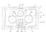
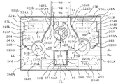
図1〜図16は、本発明の実施の態様1に係る加熱調理装置の異常報知システムを説明するものである。すなわち、図1は加熱調理装置の設置状態における全体斜視図であり、図2は全体の平面図、図3は全体の横断面図、図4は図3の横断面の位置から更に下方位置における横断面図、図5は本体前方の上部縦断面図である。
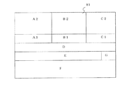
図6は全体の電気回路図、図7は表示用の駆動回路と外部出力部及び画像表示機器の主要構成を示すブロック図、図8は本体の上面操作部と中央表示・入力部周辺を示す要部平面図である。
図9は中央表示・入力部の画面を示す説明図、図10は上面操作部と中央表示・入力部を示す平面図、図11は上面操作部と中央表示・入力部を示す平面図、図12は上面操作部と中央表示・入力部を示す平面図である。
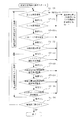
図13は調理動作開始前の制御動作を説明するためのフローチャート(その1)、図14は調理動作開始前の制御動作を説明するためのフローチャート(その2)、図15は調理動作開始後の制御動作を説明するためのフローチャート(その1)、図16は調理動作 開始後の制御動作を説明するためのフローチャート(その2)である。
なお、各図において同じ部分または相当する部分には同じ符号を付し、一部の説明を省略する。
[Embodiment 1]
1-16 demonstrates the abnormality alerting | reporting system of the heat cooking apparatus which concerns on Embodiment 1 of this invention. That is, FIG. 1 is an overall perspective view of the cooking device installed, FIG. 2 is an overall plan view, FIG. 3 is an overall cross-sectional view, and FIG. 4 is a further lower position from the position of the cross-section in FIG. FIG. 5 is a transverse sectional view and FIG. 5 is an upper longitudinal sectional view in front of the main body.
6 is an overall electrical circuit diagram, FIG. 7 is a block diagram showing the main configuration of a display drive circuit, an external output unit, and an image display device, and FIG. 8 shows the upper surface operation unit of the main body and the periphery of the central display / input unit. It is a principal part top view.
FIG. 9 is an explanatory view showing a screen of the central display / input unit, FIG. 10 is a plan view showing the top operation unit and the central display / input unit, and FIG. 11 is a plan view showing the top operation unit and the central display / input unit. 12 is a plan view showing the upper surface operation unit and the central display / input unit.
FIG. 13 is a flowchart (part 1) for explaining the control operation before starting the cooking operation, FIG. 14 is a flowchart (part 2) for explaining the control operation before starting the cooking operation, and FIG. 15 is a diagram after starting the cooking operation. FIG. 16 is a flowchart (No. 2) for explaining the control operation after the start of the cooking operation.
In the drawings, the same or corresponding parts are denoted by the same reference numerals, and a part of the description is omitted.

(加熱調理装置本体)
図1において、加熱調理装置本体(以下、「本体」と称す)1は平面形状が長方形であって、金属板から形成された箱形状の本体ケース2と、本体ケース2の上面開口を塞ぐ金属製板から形成された額縁状の天板3と、から構成されている。
本体1の内部には、天板3に載置された被加熱物を加熱するための電磁エネルギー又は熱エネルギーを発生する後記する加熱手段6L、6R、7と、該加熱手段の調理条件を制御する後記する制御手段200と、該制御手段に前記調理条件を入力する後記する入力手段20〜23と、該入力手段に入力された前記調理条件を表示する表示手段(統合表示部)80とを備えている。以下、それぞれについて詳細に説明する。
(The main body of the cooking device)
In FIG. 1, a cooking device main body (hereinafter referred to as “main body”) 1 has a rectangular planar shape, a box-shaped main body case 2 formed of a metal plate, and a metal that closes the upper surface opening of the main body case 2. It is comprised from the frame-shaped top plate 3 formed from the steel plate.
Inside the main body 1, heating means 6L, 6R, 7 to be described later for generating electromagnetic energy or heat energy for heating an object to be heated placed on the top board 3, and cooking conditions of the heating means are controlled. Control means 200 described later, input means 20 to 23 described later for inputting the cooking conditions to the control means, and display means (integrated display unit) 80 for displaying the cooking conditions input to the input means. I have. Hereinafter, each will be described in detail.

(天板)
天板3の上面は、非磁性ステンレス板又はアルミ板などから形成された額縁形状の枠体4によって縁取られ、その中央に設けられた大きな開口部は、耐熱強化ガラスや結晶化ガラス等の赤外線を透過させる材料からなる長方形状のトッププレート(上板に同じ)5によって密閉状態に覆われている。したがって、トッププレート5の上面から水滴などが枠体4を通じて本体1の内部に侵入しないようにしてある。
なお、トッププレート5の上面には、後記する加熱源6L、6R、7の位置を示す案内マーク6LM、6RM、7Mが、それぞれ表示されている。
(Top board)
The top surface of the top plate 3 is bordered by a frame-shaped frame 4 formed of a nonmagnetic stainless steel plate or aluminum plate, and a large opening provided in the center thereof is an infrared ray such as heat-resistant tempered glass or crystallized glass. Is covered in a sealed state by a rectangular top plate (same as the upper plate) 5 made of a material that transmits light. Therefore, water droplets or the like from the upper surface of the top plate 5 are prevented from entering the inside of the main body 1 through the frame body 4.
On the upper surface of the top plate 5, guide marks 6LM, 6RM, and 7M indicating the positions of heating sources 6L, 6R, and 7 to be described later are respectively displayed.

(右加熱源)
本体1の内部であって、トッププレート5の右側位置の下面側に、右側電磁加熱コイル(以下、「右加熱源」と称す)6Rが配置されている。右加熱源6Rの上端部がトッププレート5に接触又は微小間隙を置いて近接しており、電磁誘導加熱源となる。例えば、最大消費電力(最大火力)3kWの能力を備えたものが使用される。右加熱源6Rは誘導加熱コイル(以下、「右加熱コイル」と称す)220Rを渦巻状に1本又は複数本巻き、外形形状が円形になるように円盤形に成形されている。右加熱コイル220Rの直径(最大外径寸法)は約180mmである。
なお、トッププレート5に右加熱源6Rの上方に対応する位置に表示された円(図1において破線、図2において実線)である案内マーク6RMは、右加熱源6Rの外形位置を示すものではなく、適正な誘導加熱領域を示すものであって、印刷などによって形成されている。
(Right heating source)
A right electromagnetic heating coil (hereinafter referred to as “right heating source”) 6 </ b> R is disposed inside the main body 1 and on the lower surface side of the top plate 5 at the right side position. The upper end of the right heating source 6R is in contact with or close to the top plate 5 with a minute gap, and serves as an electromagnetic induction heating source. For example, the one having the capacity of maximum power consumption (maximum heating power) of 3 kW is used. The right heating source 6R is formed in a disc shape so that one or a plurality of induction heating coils (hereinafter referred to as “right heating coils”) 220R are spirally wound and the outer shape is circular. The diameter (maximum outer diameter dimension) of the right heating coil 220R is about 180 mm.
A guide mark 6RM, which is a circle (a broken line in FIG. 1 and a solid line in FIG. 2) displayed on the top plate 5 at a position corresponding to the upper side of the right heating source 6R, does not indicate the outer position of the right heating source 6R. It shows an appropriate induction heating area, and is formed by printing or the like.

(左加熱源)
本体1の内部であって、トッププレート5の左側位置の下面側に、左側電磁加熱コイル(以下、「左加熱源」と称す)6Lが配置されている。左加熱源6Lの上端部がトッププレート5に接触又は微小間隙を置いて近接しており、電磁誘導加熱源となる。例えば、最大消費電力(最大火力)2.5kWの能力を備えたものが使用される。左加熱源6Lは誘導加熱コイル(以下、「左加熱コイル」と称す)220Lを渦巻状に1本又は複数本巻き、外形形状が円形になるように円盤形に成形されている。左加熱コイル220Lの直径(最大外径寸法)は約180mmであるが、右加熱コイル220Rの最大火力より小さいため、170mm程度に形成することができる。
なお、トッププレート5に左加熱源6Lの上方に対応する位置に表示された円(図1において破線、図2において実線)である案内マーク6LMは、右加熱源6RLの外形位置を示すものではなく、適正な誘導加熱領域を示すものであって、印刷などによって形成されている。
(Left heating source)
A left electromagnetic heating coil (hereinafter referred to as “left heating source”) 6 </ b> L is disposed inside the main body 1 and on the lower surface side of the left side position of the top plate 5. The upper end portion of the left heating source 6L is in contact with or close to the top plate 5 with a minute gap, and serves as an electromagnetic induction heating source. For example, a device having a maximum power consumption (maximum heating power) of 2.5 kW is used. The left heating source 6L is formed in a disk shape so that one or more induction heating coils (hereinafter referred to as “left heating coil”) 220L are wound in a spiral shape and the outer shape is circular. The left heating coil 220L has a diameter (maximum outer diameter dimension) of about 180 mm, but can be formed to about 170 mm because it is smaller than the maximum heating power of the right heating coil 220R.
A guide mark 6LM which is a circle (a broken line in FIG. 1 and a solid line in FIG. 2) displayed on the top plate 5 at a position corresponding to the upper side of the left heating source 6L does not indicate the outer position of the right heating source 6RL. It shows an appropriate induction heating area, and is formed by printing or the like.

左加熱源6Lと右加熱源6Rとは、それぞれ独立して通電とその電力量が制御され、火力も別個に設定できるように後記する通電制御回路200に電気的に接続されている。
図3、図5および図6に示すように、左加熱源6Lおよび右加熱源6Rの何れも、通電時に渦電流を発生するように渦状に巻かれた左加熱コイル220Lおよび右加熱コイル220Rと、左加熱コイル220Lおよび右加熱コイル220Rを収容した左保持枠335Lおよび右保持枠335Rと、左保持枠335Lおよび右保持枠335Rの下面の全体やその一部を覆うフェライト製板の左磁束漏れ防止板331Lおよび右磁束漏れ防止板331R等によって構成されている。
なお、以下の説明において、左右に配置された部材について共有する内容については、名称における「左、右」および符号における「L、R」の記載を省略する場合がある。
The left heating source 6L and the right heating source 6R are electrically connected to an energization control circuit 200 which will be described later so that energization and the amount of electric power thereof are controlled independently, and the heating power can be set separately.
As shown in FIGS. 3, 5, and 6, the left heating source 6 </ b> L and the right heating source 6 </ b> R are both a left heating coil 220 </ b> L and a right heating coil 220 </ b> R that are spirally wound so as to generate an eddy current when energized. The left magnetic flux leakage of the left holding frame 335L and the right holding frame 335R housing the left heating coil 220L and the right heating coil 220R, and the ferrite plate covering the whole lower surface of the left holding frame 335L and the right holding frame 335R or a part thereof. It is configured by a prevention plate 331L, a right magnetic flux leakage prevention plate 331R, and the like.
In the following description, the description of “left, right” in the name and “L, R” in the reference may be omitted for the contents shared for the members arranged on the left and right.

そして、保持枠335は、円形で上面が開口した金属製の容器状であって、周囲壁面には、多数の通風孔330Pが設けられて、冷却風が通過するようになっている。保持枠335は、上面開口の縁が断熱材332を介してトッププレート5の下面に接触するように設置され、加熱コイル220の上面はトッププレート5の下面に対し一定の微小空隙を設けて対向するように設置されている。   The holding frame 335 is a metal container having a circular shape with an open top surface, and a large number of ventilation holes 330P are provided on the peripheral wall surface so that cooling air can pass therethrough. The holding frame 335 is installed such that the edge of the upper surface opening is in contact with the lower surface of the top plate 5 via the heat insulating material 332, and the upper surface of the heating coil 220 is opposed to the lower surface of the top plate 5 with a certain minute gap. It is installed to do.

(中央加熱源)
本体1の内部であって、トッププレート5の左右中心線(図2および図3において一点鎖線CLにて示す)上で、かつ、トッププレート5の後部寄りの位置に、中央加熱源7が配置されている。中央加熱源7は、輻射によって加熱するタイプの電気ヒータ231(例えばニクロム線やハロゲンヒータ、ラジエントヒータ)が使用され、トッププレート5を通してその上方に置かれた鍋等の加熱調理装置具(図示せず)を加熱するものである。そして、例えば、最大消費電力(最大火力)1.2kWの能力を備えたものが使用されている。
(Central heating source)
A central heating source 7 is arranged inside the main body 1 on the left and right center line of the top plate 5 (indicated by the alternate long and short dash line CL in FIGS. 2 and 3) and closer to the rear part of the top plate 5. Has been. The central heating source 7 uses an electric heater 231 of a type heated by radiation (for example, a nichrome wire, a halogen heater, a radiant heater), and a cooking device such as a pan placed above the top plate 5 (not shown). )) Is heated. And, for example, the one having the capacity of maximum power consumption (maximum heating power) 1.2 kW is used.

電気ヒータ231は断熱性の断熱カバー7Aの内部に収納されている。断熱カバー7Aは上面全体が開口した円形の容器形状を有している。断熱カバー7Aは、直径(最大外径寸法)が約180mmで、板厚が5mmになっている。
なお、トッププレート5に中央加熱源7の上方に対応する位置に表示された円(図1において破線、図2において実線)である案内マーク7Mは、中央加熱源7の外形位置を示すものではなく、適正な誘導加熱領域を示すものであって、印刷などによって形成されている。
The electric heater 231 is accommodated in the heat insulating cover 7A. The heat insulating cover 7A has a circular container shape with the entire upper surface opened. The heat insulating cover 7A has a diameter (maximum outer diameter) of about 180 mm and a plate thickness of 5 mm.
A guide mark 7M, which is a circle (a broken line in FIG. 1 and a solid line in FIG. 2) displayed on the top plate 5 at a position corresponding to the upper side of the central heating source 7, does not indicate the outer position of the central heating source 7. It shows an appropriate induction heating area, and is formed by printing or the like.

(前面操作部)
本体ケース2の右側前面に前面操作部10が設けられている。前面操作部10には、左加熱源6L、右加熱源6R、中央加熱源7及びオーブン調理やグリル調理用の電気ヒータ(図5参照、以下、「グリルヒータ」と称す)110Aの全ての電源を一斉に投入・遮断する主電源スイッチ201(図6参照)の操作ボタン11と、右加熱源6Rの通電とその通電量(火力)を制御する制御スイッチ(図示せず)の電気接点を開閉する右操作ダイアル12Rと、同じく左加熱源6Lの通電とその通電量(火力)を制御する左制御スイッチ12(図示せず)の左操作ダイアル12Lと、中央加熱源7の通電とその通電量(火力)を制御する制御スイッチ(図示せず)の中央操作ダイアル13と、が設けられている。
そして、前面操作部10には、左操作ダイアル12Lによって左加熱源6Lに通電が行われている状態でのみ点灯する左表示灯15と、右操作ダイアル12Rによって右加熱源6Rに通電が行われている状態でのみ点灯する右表示灯14とが設けられている。
(Front operation unit)
A front operation unit 10 is provided on the right front surface of the main body case 2. The front operation unit 10 includes a left heating source 6L, a right heating source 6R, a central heating source 7, and all power sources for an electric heater 110A for oven cooking and grill cooking (refer to FIG. 5, hereinafter referred to as “grill heater”). The operation button 11 of the main power switch 201 (see FIG. 6) that turns on and off all at once and the electrical contacts of the control switch (not shown) that controls the energization of the right heating source 6R and the energization amount (thermal power) are opened and closed. The right operation dial 12R, the left operation dial 12L of the left control switch 12 (not shown) for controlling the energization of the left heating source 6L and the energization amount (thermal power), and the energization of the central heating source 7 and the energization amount thereof. A central operation dial 13 of a control switch (not shown) for controlling (thermal power) is provided.
The front operation unit 10 is energized to the left heating lamp 6L by the left operation dial 12L, and the left operation lamp 12R is lit only when the left heating source 6L is energized. And a right indicator lamp 14 that is lit only when it is in the closed state.

なお、左操作ダイアル12L、右操作ダイアル12R、および中央操作ダイアル13は、使用しない状態では、図1に示されるように、前面操作部10の表面から突出しないように内側へ押し込まれており、使用する場合には、使用者が指で一度押すと前方にバネ力によって突出し、回せる状態になるものである。そして、この段階で左加熱源6Lおよび右加熱源6R及び中央加熱源7にはそれぞれ通電が開始される。
そこで、突出している左操作ダイアル12L、右操作ダイアル12R、または中央操作ダイアル13の何れかを左右に回せば、その回動の量に応じて当該加熱源の通電量が決まり、火力設定が行えるようになっている。
In addition, the left operation dial 12L, the right operation dial 12R, and the central operation dial 13 are pushed inward so as not to protrude from the surface of the front operation unit 10, as shown in FIG. In use, when the user presses once with a finger, the user protrudes forward by a spring force and can be turned. At this stage, the left heating source 6L, the right heating source 6R, and the central heating source 7 are energized.
Therefore, if any of the protruding left operation dial 12L, right operation dial 12R, or central operation dial 13 is turned to the left or right, the energization amount of the heating source is determined according to the amount of rotation, and the heating power can be set. It is like that.

さらに、前面操作部の下部分には、タイマーダイアル16、17、18が設けられている。タイマーダイアル16、17、18は、それぞれ左加熱源6L、右加熱源6R、中央加熱源7を通電開始から所望の時間だけ通電し、該所望の時間を経過した後は自動的に電源を切るタイマースイッチ(図示せず)を操作するためのものである。   Further, timer dials 16, 17, and 18 are provided in the lower part of the front operation unit. The timer dials 16, 17, and 18 energize the left heating source 6L, the right heating source 6R, and the central heating source 7 for a desired time from the start of energization, and automatically turn off the power after the desired time has elapsed. This is for operating a timer switch (not shown).

(グリル室)
本体1の内部の下半分には、区画形成されたグリル室(以下、「加熱室」と称す)19が設けられている。加熱室19は、金属板により左右、上下及び背面側の壁面が形成され、上部天井付近および底部付近に設置された電気ヒータ(図示せず)を同時又は個別に通電してロースト調理(例えば焼き魚)、グリル調理(例えばピザやグラタン)や加熱室19内の雰囲気温度を設定して調理するオーブン調理(例えば、ケーキや焼き野菜)が行えるようになっている。例えば、上部天井付近には最大消費電力(最大火力)1200Wのグリルヒータ110A(図5参照)と、底部付近には最大消費電力800Wの電気ヒータ(110B。図示せず)がそれぞれ設けられる。
(Grill room)
In the lower half of the inside of the main body 1, a compartment-formed grill chamber (hereinafter referred to as “heating chamber”) 19 is provided. The heating chamber 19 is formed of metal plates on the left, right, top, bottom, and back walls, and roasted cooking (for example, grilled fish) by simultaneously or individually energizing electric heaters (not shown) installed near the top and bottom. ), Grill cooking (for example, pizza or gratin), and oven cooking (for example, cake or grilled vegetables) in which the atmosphere temperature in the heating chamber 19 is set. For example, a grill heater 110A (see FIG. 5) with a maximum power consumption (maximum thermal power) of 1200 W is provided near the top ceiling, and an electric heater (110B, not shown) with a maximum power consumption of 800 W is provided near the bottom.

加熱室19の前面開口71はドア70によって開閉自在に覆われ、ドア70は前後方向に移動自在になるよう加熱室19に支持機構(図示せず)によって保持されている。また、ドア70の中央開口部は耐熱ガラスによって形成されて窓72が設置され、加熱室19の内部が視認できるようになっている。さらに、ドア70には一体に形成された金属製の受皿73が設けられ、油の多い調理をする場合は通常受皿73の上には金属製の焼き網(図示せず)が置かれる。   The front opening 71 of the heating chamber 19 is covered by a door 70 so as to be opened and closed, and the door 70 is held in the heating chamber 19 by a support mechanism (not shown) so as to be movable in the front-rear direction. Further, the central opening of the door 70 is formed of heat-resistant glass and a window 72 is installed so that the inside of the heating chamber 19 can be visually recognized. Further, the door 70 is provided with a metal tray 73 integrally formed. When cooking with a lot of oil, a metal grill (not shown) is usually placed on the tray 73.

枠体4の後部中心部上面に右排気口74が設けられ、表面は使用者の指や異物等が入らないようにパンチングメタルや網、細かい格子で覆われている。右排気口74は加熱室19の内部まで排気ダクト76を介して連通しており、加熱室19の内部に発生した高温空気(調理物から発生した油煙を含む)が右排気口74から本体1の外部に排出される。   A right exhaust port 74 is provided on the upper surface of the rear central portion of the frame body 4, and the surface is covered with punching metal, a net, and a fine grid so that a user's finger or foreign matter does not enter. The right exhaust port 74 communicates with the inside of the heating chamber 19 via the exhaust duct 76, and high-temperature air (including oily smoke generated from the cooked food) generated in the heating chamber 19 flows from the right exhaust port 74 to the main body 1. Is discharged outside.

また、枠体4の後部中央上面に左排気口75が設けられ、表面は使用者の指や異物等が入らないようにパンチングメタルや網、細かい格子で覆われている。左排気口75は、本体1の内部空間(後で述べる上方空間275)に連通している。   Further, a left exhaust port 75 is provided on the upper center surface of the rear portion of the frame body 4, and the surface is covered with punching metal, a net, and a fine grid so that a user's finger or a foreign object does not enter. The left exhaust port 75 communicates with an internal space (an upper space 275 described later) of the main body 1.

(上面操作部)
天板3の上面、具体的には枠体4の前部に上面操作部20が配置されている。本体1の左右中心線CL(図1および図2参照)を挟んで、左側には左加熱源6Lの左火力設定用操作部22が、中央部には中央加熱源7及び加熱室に設置された電気ヒータ(図示せず)の中央操作部23が、右側には右加熱源6Rの右火力設定用操作部21が、それぞれ配置されている。
(Top operation section)
An upper surface operation unit 20 is disposed on the upper surface of the top plate 3, specifically, the front portion of the frame body 4. A left heating power setting operation unit 22 of the left heating source 6L is installed on the left side of the left and right center line CL (see FIGS. 1 and 2) of the main body 1, and the central heating source 7 and the heating chamber are installed in the center. A central operation unit 23 of the electric heater (not shown) is arranged on the right side, and a right heating power setting operation unit 21 of the right heating source 6R is arranged on the right side.

(右火力設定用操作部)
図8において、右火力設定用操作部21には、使用者が1度押圧するだけで右加熱源6Rの火力を簡単に設定することができる右ワンタッチキー部24が設けられている。右ワンタッチキー部24は、弱火力キー25、中火力キー26、および強火力キー27の3つのワンタッチキーを備えている。例えば、弱火力キーは右加熱源6Rの火力を300Wに設定し、中火力キー26は750Wに設定し、強火力キーは2.5kWに設定する。
さらに、右ワンタッチキー部24の右端部に強火力キー(以下、「3kWキー」と称す)86が設けられ、右加熱源6Rの火力を強力(例えば、3kW)にしたい場合、これを押圧操作する。
(Right heating power setting operation section)
In FIG. 8, the right heating power setting operation unit 21 is provided with a right one-touch key unit 24 that can easily set the heating power of the right heating source 6 </ b> R only by pressing once by the user. The right one-touch key section 24 includes three one-touch keys, a low heat key 25, a medium heat key 26, and a strong heat key 27. For example, the weak heating power key sets the heating power of the right heating source 6R to 300 W, the middle heating power key 26 is set to 750 W, and the strong heating power key is set to 2.5 kW.
Further, a strong heating power key (hereinafter referred to as “3 kW key”) 86 is provided at the right end portion of the right one-touch key portion 24, and when it is desired to increase the heating power of the right heating source 6R (for example, 3 kW), a pressing operation is performed. To do.

(左火力設定用操作部)
なお、左加熱源6Lの火力設定のための左火力設定用操作部22には、右火力設定用操作部21(右ワンタッチキー部24が設置されている)と同様なワンタッチキーが設置されている。したがって、例えば、火力を300W、750W、または2.5kWの何れかに設定できるようになっている。
(Left thermal power setting operation section)
The left heating power setting operation unit 22 for setting the heating power of the left heating source 6L is provided with a one-touch key similar to the right heating power setting operation unit 21 (the right one-touch key unit 24 is installed). Yes. Therefore, for example, the thermal power can be set to 300 W, 750 W, or 2.5 kW.

(中央操作部)
中央操作部23には、図8に示されるように、ロースト調理、オーブン調理及びグリル調理に用いられるグリルヒータ110A等の通電を開始する操作スイッチ(図示せず)の操作ボタン92と、その通電を停止する操作スイッチ(図示せず)の操作ボタン29が並べて設けられている。
また、中央操作部23には、グリルヒータ110A等によるグリル調理や左加熱源6L、右加熱源6Rによる電磁調理における制御温度を、1度ずつ加算的又は減算的に設定する温度調節スイッチ(図示せず)の操作ボタン300、310が横一列に設けられている。
(Central control unit)
As shown in FIG. 8, the central operation unit 23 includes an operation button 92 of an operation switch (not shown) for starting energization of a grill heater 110 </ b> A used for roast cooking, oven cooking, and grill cooking, and energization thereof. Operation buttons 29 of operation switches (not shown) for stopping the operation are provided side by side.
Further, the central operation unit 23 is provided with a temperature adjustment switch (see FIG. 5) for setting the control temperature in the grill cooking by the grill heater 110A or the like and the electromagnetic cooking by the left heating source 6L and the right heating source 6R one by one in an additive or subtractive manner. Operation buttons 300 and 310 (not shown) are provided in a horizontal row.

さらに、中央操作部23には便利メニューキー93が設けられている。すなわち、揚げ物調理(左加熱源6L、右加熱源6Rを使用)、揚げ物予熱状態表示(左加熱源6L、右加熱源6Rを使用し、油を所定の予熱温度まで加熱)、タイマー調理(左加熱源6L、右加熱源6R、中央加熱源7、加熱室19の内部に設けた二つのグリルヒータ110A等をタイマーカウンターにて設定した時間中だけ通電して調理)を設定する際に押圧すれば、簡単に中央表示・入力部80に所望の入力画面や状態表示画面を読み出せる。   Furthermore, a convenient menu key 93 is provided in the central operation unit 23. In other words, deep-fried food cooking (left heating source 6L and right heating source 6R are used), deep-fried food preheating status display (left heating source 6L and right heating source 6R are used to heat oil to a predetermined preheating temperature), timer cooking (left When the heating source 6L, the right heating source 6R, the central heating source 7, the two grill heaters 110A provided in the heating chamber 19 are energized only during the time set by the timer counter and set) Thus, a desired input screen and status display screen can be easily read out to the central display / input unit 80.

また、中央加熱源7の電源の入・切を操作するための制御スイッチ(図示せず)の操作ボタン94が設けられている。
さらに、操作ボタン29の右側には、ハードボタンからなる右IH便利メニューボタン93aが設けられており、これは右加熱源6Rについての各種の設定をするための設定ボタンである。同様な設定ボタンは左加熱源6Lについても設けられている(図示省略)。
Further, an operation button 94 of a control switch (not shown) for operating on / off of the power source of the central heating source 7 is provided.
Further, a right IH convenient menu button 93a including a hard button is provided on the right side of the operation button 29. This is a setting button for performing various settings for the right heating source 6R. A similar setting button is also provided for the left heating source 6L (not shown).

34Rは、タイマーカウンター(図示せず)をスタートさせるスタートスイッチ(以下、「タイマースイッチ」と称す)であり、操作部21の右端部に設けてあり、使用者が1度押圧すると、その時点から時間が計測され、トッププレート5の右前方隅部に設けられた右液晶表示部35R(トッププレート5の下面近傍にあり、トッププレート5を介してその上方)に表示光を透過させて経過時間が「分」と「秒」単位で表示される。   Reference numeral 34R denotes a start switch (hereinafter referred to as “timer switch”) for starting a timer counter (not shown), which is provided at the right end of the operation unit 21. When the user presses it once, The time is measured and the elapsed time is obtained by transmitting the display light to the right liquid crystal display unit 35R (located near the lower surface of the top plate 5 and above the top plate 5) provided at the right front corner of the top plate 5. Is displayed in units of “minutes” and “seconds”.

同じく操作部21に右揚げ物選択スイッチ36Rが設けられ、使用者がこれを1度押圧すると、右加熱源6Rによる揚げ物(天ぷら)鍋の油の温度を180℃に初期設定することができ、その後使用者は右加熱源6Rの火力を、右操作ダイアル12Rを操作して揚げ物に適する任意の適温、例えば200℃に設定することができる。   Similarly, a right-fried food selection switch 36R is provided in the operation unit 21, and when the user presses it once, the temperature of the oil in the fried food (tempura) pan by the right heating source 6R can be initialized to 180 ° C., and then The user can set the heating power of the right heating source 6R to any appropriate temperature suitable for fried food, for example, 200 ° C., by operating the right operation dial 12R.

左側の左火力設定用操作部22にも、右火力設定用操作部21と同様に、左タイマースイッチ34Lと、左液晶表示部35L(図1参照)と、左揚げ物選択スイッチ36Lと、の3つが設けられている。そして、左タイマースイッチ34Lと右タイマースイッチ34R、左液晶表示部35Lと右液晶表示部35R、左揚げ物選択スイッチ36Lと右揚げ物選択スイッチ36R、とは、それぞれ本体1の左右中心線CLを挟んで左右対象的位置に設けられている。   Similarly to the right heating power setting operation unit 21, the left heating power setting operation unit 22 on the left side includes a left timer switch 34L, a left liquid crystal display unit 35L (see FIG. 1), and a left fried food selection switch 36L. One is provided. The left timer switch 34L and the right timer switch 34R, the left liquid crystal display unit 35L and the right liquid crystal display unit 35R, the left deep-fried food selection switch 36L, and the right deep-fried food selection switch 36R sandwich the left and right center line CL of the main body 1, respectively. It is provided at the right and left target positions.

図8において、上記した6つの各種操作ボタン29、92、93、94、300、310、93a等は、表面が水や調理物の油などに耐える材質の薄い樹脂皮膜や金属皮膜で覆われており、使用者が指先で軽く押すことにより動作(内蔵した電気接点が導通し、入力信号発生)するように構成されている。   In FIG. 8, the above-described six various operation buttons 29, 92, 93, 94, 300, 310, 93a and the like are covered with a thin resin film or metal film of a material that can withstand water, cooking oil, etc. It is configured to operate (the built-in electrical contact is conducted and an input signal is generated) when the user presses lightly with a fingertip.

さらに、図8に示すように入力キー群91が設けられている。このキー群は6つの独立して操作可能な入力キー83、95、96、97、98、99を備えており、これらキーは、表面が調理物の油などに絶える材質の薄い樹脂皮膜や金属皮膜で覆われており、使用者が指先で軽く押すことにより動作(内蔵した電気接点が導通し、入力信号発生)するように構成されている。   Further, as shown in FIG. 8, an input key group 91 is provided. This key group is provided with six independently operable input keys 83, 95, 96, 97, 98, 99. These keys are made of a thin resin film or metal whose surface is completely cut off from cooking oil. It is covered with a film, and is configured to operate (a built-in electrical contact is conducted and an input signal is generated) when the user presses lightly with a fingertip.

上記のように、中央操作部23の各操作ボタンや入力キーを、接触式の入力キー(例えば特許第2712399号で紹介されている)を使用しなかった理由は、その種の接触式キーは静電容量の変化を検知して入力信号が発生するものであるため、調理中の水や油の飛散、また使用者が濡れた手で操作した場合などの状況を考えると、この種の加熱調理装置では誤動作が起こる懸念があるためである。これにより、実施の態様1ではより高い信頼性を確保しているが、本発明は上記接触式のキーを採用しても実現することができ、必ずしも押圧式のキーを使用しなければならない訳ではない。   As described above, the reason why the contact type input keys (for example, introduced in Japanese Patent No. 2712399) are not used as the operation buttons and input keys of the central operation unit 23 is that such contact type keys are This is a type of heating that takes into account situations such as splashing of water or oil during cooking or when the user operates with wet hands, because an input signal is generated by detecting a change in capacitance. This is because a malfunction may occur in the cooking apparatus. As a result, higher reliability is ensured in the first embodiment, but the present invention can be realized even if the contact type key is employed, and the pressing type key must be used. is not.

(火力表示ランプ)
トッププレート5の右前側で、右加熱源6Rと右火力設定用操作部21との間の位置に対応した位置に、右加熱源6Rの火力の大きさを表示する右火力表示ランプ40Rが設けられている。右火力表示ランプ40Rはトッププレート5を介して(透過させて)その下面から表示光を上面側に放つようにトッププレート5の下面近傍に設けられている。
同様に、左加熱源6Lの火力の大きさを表示する左火力表示ランプ40Lが、トッププレート5の左前側で、左加熱源6Lと左火力設定用操作部22との間の位置に対応した位置に設けられ、トッププレート5を介して(透過させて)その下面から表示光を上面側に放つようにトッププレート5の下面近傍に設けられている。
(Thermal power indicator lamp)
A right heating power display lamp 40R for displaying the magnitude of the heating power of the right heating source 6R is provided on the right front side of the top plate 5 at a position corresponding to the position between the right heating source 6R and the right heating power setting operation unit 21. It has been. The right thermal power display lamp 40R is provided in the vicinity of the lower surface of the top plate 5 so as to emit display light from the lower surface thereof through the top plate 5 (permeate).
Similarly, the left heating power display lamp 40L that displays the magnitude of the heating power of the left heating source 6L corresponds to the position between the left heating source 6L and the left heating power setting operation unit 22 on the left front side of the top plate 5. It is provided at a position, and is provided in the vicinity of the lower surface of the top plate 5 so that display light is emitted from the lower surface thereof through the top plate 5 (transmitted).

なお、右加熱源6R用の右火力表示ランプ40Rは、火力120Wから最大火力3kWまで12段階で表示できるようになっている。そして、これら12段階の火力を発光で示すために、右火力表示ランプ40Rは、図6に示す回路図の通り12個の発光ダイオード246〜257(発光素子)を直線的に配置してある。例えば、火力1である場合は、発光ダイオード1の246のみが点灯し、その赤い光を使用者はトッププレート5の表面上から容易に目視することができる。
同様に、左加熱源6L用の左火力表示ランプ40Lは、図示していないが、火力120Wから最大火力2.5kWまでの間を11段階で表示できるようになっている。
The right heating power display lamp 40R for the right heating source 6R can display in 12 stages from a heating power of 120 W to a maximum heating power of 3 kW. And in order to show these 12 steps | paragraphs of thermal power with light emission, the right thermal power display lamp 40R has arrange | positioned 12 light emitting diodes 246-257 (light emitting element) linearly as the circuit diagram shown in FIG. For example, in the case of fire power 1, only the light emitting diode 246 is lit, and the user can easily see the red light from the surface of the top plate 5.
Similarly, although the left heating power display lamp 40L for the left heating source 6L is not shown in the drawing, the heating power from 120 W to the maximum heating power of 2.5 kW can be displayed in 11 steps.

(主電源スイッチ)
主電源スイッチ201(図6参照)の操作ボタン11と、右加熱源6Rの通電とその通電量(火力)を制御する制御スイッチ(図示せず)の電気接点を開閉する右操作ダイアル12Rと、左加熱源6Lの通電とその通電量(火力)を制御する制御スイッチ(図示せず)の電気接点を開閉する左操作ダイアル12Lとにより、中央操作部23、右加熱源6Rの右火力設定用操作部21、左加熱源6Lの左火力設定用操作部22の電源が遮断される構成になっている。したがって、例えば主電源スイッチ201を開成(OFF)すれば、それ以後、右操作ダイアル12Rおよび左操作ダイアル12Lの操作は一斉に無効となる。
(Main power switch)
An operation button 11 of the main power switch 201 (see FIG. 6), a right operation dial 12R for opening and closing an electrical contact of a control switch (not shown) for controlling energization of the right heating source 6R and its energization amount (thermal power), For setting the right heating power of the central operation unit 23 and the right heating source 6R by energizing the left heating source 6L and the left operation dial 12L for opening and closing the electrical contacts of a control switch (not shown) for controlling the energization amount (thermal power). The power supply of the operation part 21 and the left heating power setting operation part 22 of the left heating source 6L is cut off. Therefore, for example, if the main power switch 201 is opened (OFF), then the operations of the right operation dial 12R and the left operation dial 12L are invalidated simultaneously.

(表示手段)
統合表示手段(以下「中央表示・入力部」と称す)80が、トッププレート5の左右方向の中央部で、前後方向の前側に設けられている。中央表示・入力部80は、液晶パネルを主体に構成され、トッププレート5を介して(透過させて)その下面から表示光を上面側に放つようにトッププレート5の下面近傍に設けられている。
中央表示・入力部80は、左加熱源6L、右加熱源6R、中央加熱源7及び加熱室19の内部に設けたグリルヒータ110A等の通電状態(火力や時間等)を入力したり、確認したりすることができるものである。すなわち、(i)加熱源6の機能(調理動作中であるかどうか等)と、(ii)中央加熱源7の機能(調理中であるかどうか等)と、(iii)グリル調理の場合には、加熱室19内部でグリル調理を行う場合の操作手順や機能(例えば、現在ロースタ、グリル、オーブンの調理の何れが行われているかどうか)と、が文字やイラスト、グラフなどによって表示されるものである。具体的な構造と表示動作については以下に説明する。
(Display means)
An integrated display means (hereinafter referred to as “center display / input unit”) 80 is provided at the center in the left-right direction of the top plate 5 on the front side in the front-rear direction. The central display / input unit 80 is mainly composed of a liquid crystal panel, and is provided in the vicinity of the lower surface of the top plate 5 so that display light is emitted from the lower surface thereof through the top plate 5 (transmitted). .
The central display / input unit 80 inputs or confirms the energization state (heating power, time, etc.) of the left heating source 6L, the right heating source 6R, the central heating source 7 and the grill heater 110A provided in the heating chamber 19, etc. It is something that can be done. That is, (i) the function of the heating source 6 (whether cooking is in progress, etc.), (ii) the function of the central heating source 7 (whether cooking is in progress, etc.), and (iii) grill cooking Is displayed with characters, illustrations, graphs, and the like as to the operation procedures and functions (for example, whether roaster, grill, or oven cooking is currently performed) when grill cooking is performed inside the heating chamber 19. Is. A specific structure and display operation will be described below.

図1において、60は本発明の加熱調理装置が設置された流し台64の設置空間である台所の壁65に取り付けられた液晶TV又は液晶モニター等の画像表示器であり、これはパソコンの画面として接続して使用されるような周知のものでも良い。61は画像表示器60の電源コード、62は画像表示器60に対して画像信号を送出する接続ケーブルで、後述する通電制御回路200に駆動回路244を介して接続される。   In FIG. 1, reference numeral 60 denotes an image display such as a liquid crystal TV or a liquid crystal monitor attached to a kitchen wall 65, which is an installation space of a sink 64 in which the cooking device of the present invention is installed. The well-known thing used by connecting may be used. Reference numeral 61 denotes a power cord of the image display 60, and 62 denotes a connection cable for sending an image signal to the image display 60. The connection cable is connected to an energization control circuit 200 described later via a drive circuit 244.

画像表示器60の使用は使用者の任意であり、接続ケーブル62の端部にある接続プラグ62Aを簡単に調理装置本体1の出力端子244H(図7参照)から取り外せるので、電源接続口63に接続しない状態で加熱調理装置を使用しても何ら調理動作には影響がなく、また中央表示・入力部80の動作にも影響はない。画像表示器60の上面、左右側面、下面及び前面の5面全体はカバー66によって覆われ、画像表示器60の前面、すなわち加熱調理装置本体1に面する側は透明な材質で構成されているか、または透明な板で覆われた窓を設けており、画像表示器60に着脱自在に取り付けられている。   The use of the image display device 60 is arbitrary by the user, and the connection plug 62A at the end of the connection cable 62 can be easily removed from the output terminal 244H (see FIG. 7) of the cooking apparatus main body 1. Even if the cooking device is used without being connected, there is no influence on the cooking operation, and there is no influence on the operation of the central display / input unit 80. Is the entire upper surface, left and right side surfaces, the lower surface and the front surface of the image display device 60 covered by the cover 66, and is the front surface of the image display device 60, that is, the side facing the heating cooking apparatus body 1 made of a transparent material? Alternatively, a window covered with a transparent plate is provided and is detachably attached to the image display 60.

中央表示・入力部80は、周知のドットマトリックス型液晶画面で構成されている。このため高精細(320×240ピクセルの解像度を備えているQVGAや640×480ドット、16色の表示が可能なVGA相当)の画面を実現でき、文字を表示する場合でも多数の文字を表示することができる。
図8はその一例を模式的に表示したものである。図8に記載のように、情報を表示する画面区域81は合計10個のエリアに割り当ててあり、
左加熱源6Lの対応エリアA1、A2と、
中央加熱源7の対応エリアB1、B2と、
右加熱源6Rの対応エリアC1、C2と、
グリルやオーブン調理用のグリルヒータ(加熱源に同じ)110A等の対応エリアDと、
使用者に各種調理における注意や参考情報を表示するガイドエリアEと、
上記入力キー群91の各入力キー83、95〜99に隣接し、そのキーで入力可能な機能を個別に表示する、互いに独立した6つの表示キー84、100、101、102、103、104を(仮想的に)表示するキー表示エリアFと、
Tips表示エリアGと、
をそれぞれ備えている。
The central display / input unit 80 includes a known dot matrix type liquid crystal screen. For this reason, a high-definition screen (QVGA having a resolution of 320 × 240 pixels or 640 × 480 dots, equivalent to VGA capable of displaying 16 colors) can be realized, and a large number of characters are displayed even when characters are displayed. be able to.
FIG. 8 schematically shows an example thereof. As shown in FIG. 8, the screen area 81 for displaying information is allocated to a total of 10 areas,
Corresponding areas A1, A2 of the left heating source 6L,
Corresponding areas B1, B2 of the central heating source 7,
Corresponding areas C1, C2 of the right heating source 6R,
Corresponding area D such as grill heater for grill and oven cooking (same as heating source) 110A,
Guide area E that displays cautions and reference information for various cooking to the user,
Six display keys 84, 100, 101, 102, 103, and 104 that are adjacent to each of the input keys 83 and 95 to 99 of the input key group 91 and that individually display functions that can be input with the keys are displayed. A key display area F to display (virtually);
Tips display area G,
Each is equipped.

上記の合計10個の各エリア(表示領域)は、中央表示・入力部80の液晶画面の上に実現されたものではあるが、画面自体に物理的に個別に形成され、又は区画されているものではない。すなわち、画面表示のソフトウエア(マイコンのプログラム)により確立されたものであるので、そのソフトウエアによりその都度面積や形、位置を変えることは可能であるが、使用者の使い勝手を考え、左加熱源6L、中央加熱源7、右加熱源6Rなど各加熱源の並び順序に合わせて常に同じ並び順序にしている。つまり、画面上では左側に左加熱源6L、真中に中央加熱源7、右側に右加熱源6Rについての情報が表示される。   Each of the 10 areas (display areas) is realized on the liquid crystal screen of the central display / input unit 80, but is physically formed or partitioned on the screen itself. It is not a thing. In other words, since it is established by screen display software (microcomputer program), it is possible to change the area, shape, and position each time with that software. The arrangement order is always the same in accordance with the arrangement order of the heating sources such as the source 6L, the central heating source 7, and the right heating source 6R. That is, on the screen, the left heating source 6L is displayed on the left side, the center heating source 7 is displayed in the middle, and the right heating source 6R is displayed on the right side.

左加熱源6Lに対応して、左加熱源6Lのための火力(加熱量)などの「第一条件」設定の正常状態を表示する第一の表示エリアA1と、左加熱源6Lのための調理時間、設定温度など(第一条件よりも多数の種類がある)「第二条件」の設定状態並びに「温度や電流、電圧などの物理量」異常状態を表示する第二の表示エリアA2と、の2つのエリアから構成されている。   Corresponding to the left heating source 6L, a first display area A1 for displaying the normal state of the “first condition” setting such as the heating power (heating amount) for the left heating source 6L, and the left heating source 6L A second display area A2 for displaying a setting state of "second condition" such as cooking time and set temperature (there are more types than the first condition) and an abnormal state of "physical quantities such as temperature, current and voltage"; It consists of two areas.

同様に、中央加熱源7に対応して、中央加熱源7のための火力などの「第一条件」設定の正常状態を表示する第一の表示エリアB1と、中央加熱源7のための調理時間、設定温度など(第一条件よりも多数の種類がある)「第二条件」の設定状態並びに「温度や電流、電圧などの物理量」異常状態を表示する第二の表示エリアB2と、の2つのエリアから構成されている。   Similarly, corresponding to the central heating source 7, a first display area B 1 for displaying a normal state of the “first condition” setting such as the heating power for the central heating source 7, and cooking for the central heating source 7 The second display area B2 for displaying the setting state of "second condition" such as time, set temperature, etc. (there are more types than the first condition) and "physical quantities such as temperature, current, voltage, etc." It consists of two areas.

また、同様に、右加熱源6Rに対応して、右加熱源6Rのための火力などの「第一条件」設定の正常状態を表示する第一の対応エリアC1と、右加熱源6Rのための調理時間、設定温度など(第一条件より多数の種類がある)「第二条件」設定の正常状態並びに「温度や電流、電圧などの物理量」異常状態を表示する第二の表示エリアC2と、の2つのエリアから構成されている。   Similarly, corresponding to the right heating source 6R, the first corresponding area C1 for displaying the normal state of the “first condition” setting such as the heating power for the right heating source 6R, and the right heating source 6R. A second display area C2 for displaying the normal state of the “second condition” setting and the abnormal state of “physical quantities such as temperature, current, voltage” and the like (there are more types than the first condition), etc. These areas are composed of two areas.

図8において、キー表示エリアFと、6つの入力キー83、95〜99との配置関係が示されている。キー表示エリア部分Fに設けた6つの各キー(以下、表示キー又はソフトキーともいう)84、100〜104は、場面によって機能が変わる液晶画面内での仮想キーであり、実際の操作は各表示キー84、100〜104に対応して近接配置されている入力キー(F1〜F6、ファンクションキーともいう)83、95〜99を操作することにより、各表示キー84、100〜104を操作したことに相当する操作信号が(後述する通電制御回路200に)入力されることになる。   In FIG. 8, the arrangement relationship between the key display area F and the six input keys 83, 95 to 99 is shown. Six keys (hereinafter also referred to as display keys or soft keys) 84, 100 to 104 provided in the key display area portion F are virtual keys in the liquid crystal screen whose functions change depending on scenes. Each display key 84, 100-104 was operated by operating input keys (F1-F6, also called function keys) 83, 95-99 arranged in close proximity to display keys 84, 100-104. An operation signal corresponding to this is input (to an energization control circuit 200 described later).

入力キーを個別に表示する方法として、キー部分に文字を浮かび上がらせたり、発光ダイオード等により点灯させたり、キー部分の色彩や輝度を強調したり、色々な方法があるが、実施の態様1では、入力できる条件の前提となる各種パラメータ(対象となる加熱源、加熱温度や時間、通電量など)設定に必要な文字と記号(矢印など)を表示キー部分84、100〜104に表示するように構成している。   There are various methods for individually displaying the input keys, such as highlighting characters on the key portions, lighting them with light emitting diodes, etc., and emphasizing the color and brightness of the key portions. Characters and symbols (such as arrows) necessary for setting various parameters (target heating source, heating temperature and time, energization amount, etc.) that are preconditions for input conditions are displayed on the display key portions 84 and 100 to 104. It is configured.

表示キー104の右側手前には、ハードキーからなるインフォーメーションキー(Tipsキー)85が設けられている。このキーは、キー104の上方のTips表示エリアGに対応しており、その表示エリアに特定の記号、例えば参考情報(インフォーメーション)を意味する「i」を○で囲んだ記号(以下、「(i)」と称す)が表示された場合、このインフォーメーションキー85を押せば、調理に役立つ詳しい情報などを文字で中央表示・入力部80のガイドエリアEに表示させることができる。具体的には、つぎのような情報をガイドエリアEに表示する。
(1)ユーザーの操作・意図とは関係ない動作に対するお知らせ(切り忘れ防止/脱煙フィルター自動クリーニング等)。
(2)自動調理(揚げ物、自動グリル)を安全に、また上手に使いこなすために行ってもらいたい内容。
(3)調理全般に関して加熱調理装置特有の癖(焼きムラ等)のお知らせ。
(4)加熱調理装置の安全面のお願いや・警報内容、警報に対する対応方法。
An information key (Tips key) 85 including a hard key is provided in front of the display key 104 on the right side. This key corresponds to the Tips display area G above the key 104. In the display area, a specific symbol, for example, a symbol in which “i” meaning reference information (information) is circled (hereinafter, “ If the information key 85 is pressed, detailed information useful for cooking can be displayed in the guide area E of the central display / input section 80 by pressing the information key 85. Specifically, the following information is displayed in the guide area E.
(1) Information on actions not related to user operations / intentions (preventing forgetting to cut / automatic cleaning of smoke filter, etc.).
(2) Contents that you would like us to go to use automatic cooking (fried food, automatic grill) safely and well.
(3) Notice of rice cake (baking unevenness, etc.) specific to cooking equipment regarding cooking in general.
(4) Safety request of the cooking device, alarm contents, and response methods for alarms.

(動作説明)
図8および図10は、表示キー84、100〜104と入力キー(ファンクションキー)83、95〜99の表示例を示している。6つの表示キー84、100〜104はそれぞれその下方に個別にLEDがそれぞれ配置されており、操作場面毎に有効な入力用表示キーを点灯する。例えば、図10に示す表示キー100〜104は有効(アクティブ状態)になっている。図中、「AM」はアクティブ状況にあることを模式的に示したアクティブマークである。実際はこのような特定形状の点灯を行うだけではなく、表示キー84、100〜104の全域や輪郭だけを明るくし、又は色を変える等の方法で、アクティブ状況にあることを示しても良い。
(Description of operation)
8 and 10 show display examples of the display keys 84 and 100 to 104 and the input keys (function keys) 83 and 95 to 99. FIG. Each of the six display keys 84 and 100 to 104 is individually provided with an LED, and an effective input display key is lit for each operation scene. For example, the display keys 100 to 104 shown in FIG. 10 are valid (active state). In the figure, “AM” is an active mark schematically showing that the vehicle is in an active state. Actually, not only lighting in a specific shape like this, but it is also possible to indicate the active state by a method such as brightening the entire area or outline of the display keys 84, 100 to 104, or changing the color.

表示キー84、100〜104の内、操作しても無効なキーについては、グレイアウト(コントラスト及び文字内容を薄く表示する)や非表示(キー外形形状のみを薄く表示する)により区別をするようにしている。図10では、1つの表示84だけが、グレイアウトや非表示になっている(実際には「初期画面」という文字さえ表示されない)。   Among the display keys 84 and 100 to 104, keys that are invalid even if operated are distinguished by gray-out (displays the contrast and character content in a thin color) or non-display (displays only the key outline shape in a thin color). I have to. In FIG. 10, only one display 84 is grayed out or hidden (actually, even the characters “initial screen” are not displayed).

また、ファンクションキー83、95〜99についても、その下方に個別に設けたLEDの点灯有無により、有効なファンクションキーが目視で区別できるようにしている。
図10において、表示キー84に対応するファンクションキー83は、LEDが点灯しておらず、このLEDが点灯していないファンクションキー83を押しても、後述する通電制御回路200の中には有効な操作信号が上面操作部20より取り込まれない(通電制御回路200の動作を定める制御プログラムに対し、有効な操作指令信号にならない)。
Further, the function keys 83 and 95 to 99 are configured such that effective function keys can be distinguished visually depending on whether or not an LED individually provided below the function keys is lit.
In FIG. 10, the function key 83 corresponding to the display key 84 is not lit, and even if the function key 83 whose LED is not lit is pressed, an operation that is effective in the energization control circuit 200 to be described later. A signal is not captured from the upper surface operation unit 20 (it is not a valid operation command signal for the control program that determines the operation of the energization control circuit 200).

つまり、実施の態様1では、使用者が中央表示・入力部80を見た場合、所望の表示キーを少しでも早く、簡単に認識・理解できるよう不要な表示キーにはこのように何も選択する機能名や加熱源の名称を表示しないようにプログラムしてある。また、入力が有効な表示キーは文字や発光、色などで判別できるようにしている。さらに、その有効な表示キーに対応するファンクションキー83、95〜99も、それが有効な(アクティブ)状態であることを色や光等で表示している。   That is, in the first embodiment, when the user looks at the central display / input unit 80, any desired display key is selected in this way so that the desired display key can be easily recognized and understood as soon as possible. It is programmed not to display the function name or the name of the heating source. In addition, display keys that are valid for input can be identified by characters, light emission, color, and the like. Further, the function keys 83 and 95 to 99 corresponding to the effective display keys also indicate that they are in an effective (active) state by color, light, or the like.

以上の通り、6つの表示キー84、100〜104のアクティブ状態と、6つのファンクションキー83、95〜99のアクティブ状態とは、入力の場面毎に変化するが、常に両者は対応している。例えば、図10において、表示キー100が有効である(アクティブマークAMが点灯してアクティブ状態であることが示されている)場面では、ファンクションキー95も有効(アクティブ状態)になっている。   As described above, the active state of the six display keys 84 and 100 to 104 and the active state of the six function keys 83 and 95 to 99 change for each input scene, but they always correspond to each other. For example, in FIG. 10, in a scene where the display key 100 is valid (the active mark AM is lit to indicate that it is active), the function key 95 is also valid (active).

図10では、中央表示・入力部80の画面区域81が初期状態を表示しているため、表示キー84に対応するファンクションキー83は非アクティブになっており、このキー83を押圧しても、これに対応する表示キー84では入力操作できないことを示している。
表示キー84には「初期画面」との説明文字が表示されているが、既に初期画面になっているので、表示キー84を操作する必要性がないからである(この初期画面という表示自体を表示キー84に表示させないこともできるが、実施の態様1の説明上、図10では表示させている)。
In FIG. 10, since the screen area 81 of the central display / input unit 80 displays the initial state, the function key 83 corresponding to the display key 84 is inactive, and even if this key 83 is pressed, The corresponding display key 84 indicates that an input operation cannot be performed.
This is because there is no need to operate the display key 84 because the display key 84 is displayed with the explanatory text “initial screen”, but it is already the initial screen (the display itself of this initial screen is not displayed). (The display key 84 may not be displayed, but is displayed in FIG. 10 for the sake of description of the first embodiment).

図8で、「戻る」という表示キー100は、調理条件の入力などを行っていく過程で一つ前の入力画面や表示画面に戻したい場合に押すものである。「初期画面」の表示キー84は、どのような段階でも一挙に初期画面に戻したい場合に操作する。   In FIG. 8, a display key 100 “Return” is pressed when it is desired to return to the previous input screen or display screen in the course of inputting cooking conditions. The “initial screen” display key 84 is operated when it is desired to return to the initial screen at any stage.

図11は、図10の状態から使用者が3kWキー86(図8参照)を押した場合の中央表示・入力部80と入力キー(ファンクションキー)83、95〜99の表示例を示した説明図である。3kWキー86が押されると、3kWキー86の入力信号で通電制御回路200にメニュー選択の指令が入力され、その制御回路はこの中央表示・入力部80に対し、図11の画面を表示するよう指令を出す。   FIG. 11 shows an example of display of the central display / input unit 80 and the input keys (function keys) 83 and 95 to 99 when the user presses the 3 kW key 86 (see FIG. 8) from the state of FIG. FIG. When the 3 kW key 86 is pressed, a menu selection command is input to the energization control circuit 200 by an input signal of the 3 kW key 86, and the control circuit displays the screen of FIG. 11 on the central display / input unit 80. Issue a command.

中央表示・入力部80における、右加熱源6RのエリアC2は自動的に面積が数倍に拡大され、表示エリアC1に表示された文字で、その火力のレベルが12段階中の12(最大値)である3kWに設定されることが分かる。この火力については下げることはできないので、火力を下げるための表示キー102は非アクティブであり、これに対応したファンクションキー97は非アクティブになる。   In the central display / input unit 80, the area C2 of the right heating source 6R is automatically enlarged several times, and is displayed on the display area C1 with the heating power level being 12 out of 12 levels (maximum value). It can be seen that 3 kW is set. Since this thermal power cannot be lowered, the display key 102 for lowering the thermal power is inactive, and the corresponding function key 97 is inactive.

通電時間は初期設定では2分、5分、10分の内から、2分が表示されるので、この2分を5分に変えたい場合は、3kWキーを再度押すか、又は時間や温度を増加させる「→」の記号が表示された表示キー103を操作するため、ファンクションキー98を押せば良い。この場合、時間を(5分や10分に)長くするためのファンクションキー98はアクティブ表示になっており、逆に時間を短くするための表示キー102に対応するファンクションキー97はグレイアウトになっている(2分以下に下げることはできないため)。しかし、もし5分に設定したあと、2分に戻す場合は、このファンクションキー97はアクティブになっているので、ファンクションキー97を押せば良い。   The energization time is 2 minutes from the initial setting of 2 minutes, 5 minutes, and 10 minutes. If you want to change this 2 minutes to 5 minutes, press the 3kW key again, or change the time and temperature. In order to operate the display key 103 on which the symbol “→” to be increased is displayed, the function key 98 may be pressed. In this case, the function key 98 for increasing the time (to 5 minutes or 10 minutes) is active display, and conversely, the function key 97 corresponding to the display key 102 for shortening the time is grayed out. (Because it cannot be lowered to less than 2 minutes). However, if the time is set to 5 minutes and then returned to 2 minutes, the function key 97 is active, so the function key 97 may be pressed.

図11に示す通り、中央表示・入力部80のガイドエリアEには調理時間が2分、5分、10分の内から選べること。またその選ぶ方法は3kWキーを押すか、又は「→」、「←」の記号が表示された表示キー102、103をファンクションキー97、98で操作すれば良いことが使用者は容易に認識できる。   As shown in FIG. 11, the cooking time can be selected from 2 minutes, 5 minutes, and 10 minutes in the guide area E of the central display / input unit 80. In addition, the user can easily recognize that the 3 kW key can be selected or the display keys 102 and 103 on which the symbols “→” and “←” are displayed can be operated with the function keys 97 and 98. .

以上のように、ガイドエリアEには、例えば50文字までの文字表示ができるようにしてあり、その主な表示内容は、各種キーの操作機能の説明や操作手順の補助等、また重要な警報(異常運転状態の報知を含む)である。   As described above, in the guide area E, for example, up to 50 characters can be displayed, and the main display contents include explanations of operation functions of various keys, assistance of operation procedures, and important alarms. (Including notification of abnormal operating conditions).

図12に、図10の状態から使用者が右IH便利メニューキー(図8参照、以下「キー」と称す)93aを押した場合の中央表示・入力部80とファンクションキー83、95〜99の表示例が示されている。すなわち、キー93aが押されると、中央表示・入力部80における、右加熱源6RのエリアC2は自動的に面積が拡大され、左側には各種の調理メニュー(例えば、揚げ物、煮込み等)が表示され、煮込みに適する火力として火力レベルが12段階中の5である625W(弱火力)に初期設定されることが分かる。
この火力は初期設定値以外に使用者が希望する火力に変更することができるので、火力を1段階落として563W以下にしたい場合は、(その場面は図で示していないが)表示キー102を操作すべく、ファンクションキー97を1回押せば、1段階さがり、2回押せば2段階(500W)に下げることができる。逆に火力を上げる場合は、ファンクションキー98を押せば良い。
FIG. 12 shows the central display / input unit 80 and the function keys 83 and 95 to 99 when the user presses the right IH convenient menu key (see FIG. 8, hereinafter referred to as “key”) 93a from the state shown in FIG. A display example is shown. That is, when the key 93a is pressed, the area C2 of the right heating source 6R in the central display / input unit 80 is automatically enlarged, and various cooking menus (for example, fried food, stewed food) are displayed on the left side. It can be seen that the heating power level is initially set to 625 W (weak heating power), which is 5 in 12 stages, as the heating power suitable for boiling.
Since this thermal power can be changed to a thermal power desired by the user other than the initial setting value, if the thermal power is to be reduced by one step and reduced to 563 W or less, the display key 102 is pressed (although the scene is not shown in the figure). In order to operate, if the function key 97 is pressed once, the level can be lowered by one level, and if pressed twice, the level can be lowered to two levels (500 W). Conversely, to increase the heating power, the function key 98 may be pressed.

また、通電時間は上下方向の矢印が示された表示キー101を操作すれば、入力される条件が「通電時間」になる。つまり、図12において「時間:0分」という部分の時間設定が可能になる。そこで調理時間を2分に設定したい場合、ファンクションキー98を2回押す。
図12は、このように時間を設定する段階にあるため、時間(0分)を下げる(短くする)ことはないから、表示キー102が対応するファンクションキー97は非アクティブ状態である(ファンクションキー97を押しても何も入力できない)。
In addition, when the display key 101 indicated by the up and down arrows is operated, the input condition becomes “energization time”. That is, the time setting of “time: 0 minute” in FIG. 12 is possible. Therefore, to set the cooking time to 2 minutes, the function key 98 is pressed twice.
In FIG. 12, since the time is set in this way, the time (0 minutes) is not lowered (shortened), and the function key 97 corresponding to the display key 102 is in an inactive state (function key). Nothing can be entered by pressing 97).

時間設定を行わずに、また火力設定をやり直したい場合、図12の状態から表示キー101に対応したファンクションキー96を押せば、表示キー101の矢印表示の通り、入力対象を、「時間」からその上方位置に表示されている「火力」に移動させることができ、時間の欄から火力の欄に入力対象を変えることができる。   When it is desired to reset the heating power without setting the time, if the function key 96 corresponding to the display key 101 is pressed from the state of FIG. 12, the input target is changed from “time” as indicated by the arrow of the display key 101. It is possible to move to the “thermal power” displayed in the upper position, and the input target can be changed from the time field to the thermal power field.

また、調理メニューの機能設定の段階で、「煮込み」から「切タイマー」に変更したい場合は、ファンクションキー96を押せば、煮込み→保温→揚げ物→切タイマーのように巡回するから、切タイマーのところに合わせれば良い。   In addition, if you want to change from “Boiled” to “Cut Timer” at the function setting stage of the cooking menu, press Function key 96 and it will cycle through Boiled → Warm → Fried food → Cut timer. Just adjust it.

切タイマーとは加熱源6の火力をレベル1(120W)、2(300W)、3(563W)〜8(1kW)の内から選び、1時間30分(90分)以内の連続調理をタイマーにより行うことができるようにした機能であり、例えば、火力「8」で29分間だけ右加熱源6Rを通電して調理を行なうという使用ができる。なお、切タイマー運転の場合の加熱源は、中央加熱源7でも使用可能である。   With the timer, the heating power of the heating source 6 is selected from levels 1 (120 W), 2 (300 W), 3 (563 W) to 8 (1 kW), and continuous cooking within 1 hour 30 minutes (90 minutes) is performed by the timer. This is a function that can be performed. For example, the right heating source 6R can be energized for 29 minutes with a heating power of “8” for cooking. In addition, the heating source in the case of the off timer operation can also be used as the central heating source 7.

図8において、右加熱源6Rが通電され加熱中であることを点灯や点滅で示す通電マーク50が設けられている。通電マーク50は図8に示すように、各加熱源の名称を表示した右位置に現れる。   In FIG. 8, an energization mark 50 is provided to indicate that the right heating source 6R is energized and being heated by lighting or blinking. As shown in FIG. 8, the energization mark 50 appears at the right position where the names of the respective heating sources are displayed.

(制御回路)
図6は、この調理装置の制御回路の全体を示す図であり、該制御回路は、1つ又は複数のマイクロコンピュータを内蔵して構成されている通電制御回路200によって形成されている。通電制御回路200は、入力部と、出力部と、記憶部と、演算制御部と、の4つの部分から構成され、定電圧回路232を介して直流電源が供給されて、全ての加熱源(加熱手段)と中央表示・入力部80(表示手段)を制御する中心的な制御手段の役目を果たすものである。
(Control circuit)
FIG. 6 is a diagram showing the entire control circuit of the cooking apparatus, and the control circuit is formed by an energization control circuit 200 configured by incorporating one or a plurality of microcomputers. The energization control circuit 200 includes four parts, that is, an input unit, an output unit, a storage unit, and an arithmetic control unit. A direct-current power supply is supplied via a constant voltage circuit 232, and all heating sources ( It serves as a central control means for controlling the heating means) and the central display / input unit 80 (display means).

図6において、主回路の母線202A、202Bに200V電圧の電力を供給する商用電源202が接続され、主回路の一方の母線202Aに主電源スイッチ201が設けられている。そして、商用電源202に対し、互いに並列に接続された右加熱源6R用の右加熱源回路206Rと、右加熱源回路206Rと同様に構成された左加熱源6L用の左加熱源回路206Lと、中央加熱源7用の中央回路207と、グリル・オーブン用加熱源用のグリル回路208と、が設けられている。   In FIG. 6, a commercial power supply 202 that supplies power of 200V voltage is connected to buses 202A and 202B of the main circuit, and a main power switch 201 is provided on one bus 202A of the main circuit. A right heating source circuit 206R for the right heating source 6R connected in parallel to the commercial power source 202, and a left heating source circuit 206L for the left heating source 6L configured similarly to the right heating source circuit 206R. A central circuit 207 for the central heating source 7 and a grill circuit 208 for the grill / oven heating source are provided.

右加熱源回路206Rは、誘導加熱コイル220と、母線202A、202Bに入力側が接続された整流ブリッジ回路221と、この直流側出力端子に接続されたコイル222及び平滑化コンデンサ223からなる直流回路と、コイル222とコンデンサ223の接続点に1端が接続された加熱コイル220及び共振コンデンサ224の並列回路からなる共振回路と、この共振回路の他端にコレクタ側が接続されたスイッチング手段となるIGBT225と、を備えている。   The right heating source circuit 206R includes an induction heating coil 220, a rectifier bridge circuit 221 having an input side connected to the buses 202A and 202B, a DC circuit including a coil 222 and a smoothing capacitor 223 connected to the DC side output terminal. A resonance circuit composed of a parallel circuit of a heating coil 220 and a resonance capacitor 224 connected at one end to a connection point between the coil 222 and the capacitor 223, and an IGBT 225 serving as switching means having a collector side connected to the other end of the resonance circuit; It is equipped with.

IGBT225のエミッタは、平滑化コンデンサ223と整流ブリッジ回路221の共通接続点に接続されている。フライホイールダイオード226のアノードがエミッタ側になるようIGBT225のエミッタとコレクタ間に接続されている。   The emitter of the IGBT 225 is connected to a common connection point between the smoothing capacitor 223 and the rectifying bridge circuit 221. The flywheel diode 226 is connected between the emitter and collector of the IGBT 225 so that the anode is on the emitter side.

図6において、電流検出センサー227が、加熱コイル220と共振コンデンサ224の並列回路からなる共振回路225に流れる電流を検出する。電流検出センサー227の検出出力は通電制御回路200の入力部に供給され、誘導加熱に不適当な鍋などが用いられた場合や、何らかの事故などによって正規の電流値に比較して所定値以上の差の過少電流や過大電流が検出された場合は、通電制御回路200により駆動回路228を介してIGBT225が制御され、瞬時に誘導加熱コイル220の通電を停止するようになっている。   In FIG. 6, a current detection sensor 227 detects a current flowing through a resonance circuit 225 that is a parallel circuit of a heating coil 220 and a resonance capacitor 224. The detection output of the current detection sensor 227 is supplied to the input part of the energization control circuit 200, and when a pot that is inappropriate for induction heating is used, or because of some accident or the like, it exceeds a predetermined current value by a predetermined value or more. When a difference undercurrent or overcurrent is detected, the energization control circuit 200 controls the IGBT 225 via the drive circuit 228, and the energization of the induction heating coil 220 is instantaneously stopped.

右加熱源回路206Rは、誘導加熱コイル220と、コイル222及び平滑化コンデンサ223からなる直流回路と、駆動回路228と、この駆動回路によりスイッチング制御される上記IGBT225と、共振回路220と、フライホイールダイオード226と、整流ブリッジ回路221と、から構成されている。   The right heating source circuit 206R includes an induction heating coil 220, a DC circuit including the coil 222 and the smoothing capacitor 223, a drive circuit 228, the IGBT 225 that is controlled by the drive circuit, the resonance circuit 220, and a flywheel. A diode 226 and a rectifier bridge circuit 221 are included.

左加熱源回路206Lは、右加熱源回路206Rと同等の回路構成であるので説明は省略する。なお、左加熱源6Lの最大火力は、例えば、上記したように2.5kWであり、右加熱源6Rの最大火力設定3.0kWよりも小さく設計されている。また、左加熱源回路206Lおよび右加熱源回路206Rは、所謂フル・ブリッジ回路で構成しても良い。   The left heating source circuit 206L has a circuit configuration equivalent to that of the right heating source circuit 206R, and a description thereof will be omitted. Note that the maximum heating power of the left heating source 6L is, for example, 2.5 kW as described above, and is designed to be smaller than the maximum heating power setting of 3.0 kW of the right heating source 6R. Further, the left heating source circuit 206L and the right heating source circuit 206R may be configured by a so-called full bridge circuit.

電流検出センサー227は、図示していないが、左加熱源回路206Lやグリル回路208、中央回路207にもそれぞれ同様に設けられている。   Although not shown, the current detection sensor 227 is similarly provided in the left heating source circuit 206L, the grill circuit 208, and the central circuit 207, respectively.

中央回路207は、電磁リレー230と電気ヒータ231との直列回路を有し、この回路の両端が上記母線202A、202Bにそれぞれ接続されている。   The central circuit 207 has a series circuit of an electromagnetic relay 230 and an electric heater 231, and both ends of this circuit are connected to the buses 202 </ b> A and 202 </ b> B, respectively.

通電制御回路200から出力される駆動信号に基づき、赤外線の光信号を発生させる赤外線駆動回路233は、その駆動出力側に複数個(図6では3個のみ描かれている)の赤外線LED234、235、236の直列接続回路が接続されている。この直列接続回路の他端には抵抗237を介してトランジスタ238のコレクタが接続され、トランジスタ238のベースは赤外線駆動回路233に接続されている。なお、トランジスタ238のエミッタはアース接続されている。   The infrared drive circuit 233 that generates an infrared optical signal based on the drive signal output from the energization control circuit 200 includes a plurality of infrared LEDs 234 and 235 (only three are shown in FIG. 6) on the drive output side. 236 series connection circuits are connected. The other end of the series connection circuit is connected to the collector of the transistor 238 via a resistor 237, and the base of the transistor 238 is connected to the infrared drive circuit 233. Note that the emitter of the transistor 238 is grounded.

(トッププレート割れ検知)
図6において450は、ガラス製のトッププレート(上板に同じ)5が割れたことを電気的または機械的に検知して、所定の割れ検知信号を通電制御回路200に入力する割れ検知手段である。電気的に検出する手段としては、例えばトッププレート5の裏面に格子状又は網目状に貼付された導電性皮膜における電気抵抗値の変化を捉える方法がある。
また機械的に検知する手段としては、例えば圧力スイッチがある。この圧力スイッチとは、トッププレート5の下面には、通常、左加熱コイル220Lおよび右加熱コイル220R、その他これらを支える支持部材などの構造物が押し当てられているため、トッププレート5が割れた場合、その割れによってトッププレート5が局部的に上方に持ち上がり、これをトッププレート5に接触している圧力スイッチが検知して電気信号に変えるというものである。
(Top plate crack detection)
In FIG. 6, reference numeral 450 denotes crack detection means for electrically or mechanically detecting that the glass top plate (same as the upper plate) 5 is broken and inputting a predetermined crack detection signal to the energization control circuit 200. is there. As a means for electrically detecting, for example, there is a method of capturing a change in electric resistance value in a conductive film attached to the back surface of the top plate 5 in a lattice shape or a mesh shape.
As a means for mechanical detection, for example, there is a pressure switch. With this pressure switch, since the bottom plate of the top plate 5 is usually pressed against the left heating coil 220L, the right heating coil 220R, and other structures such as supporting members that support these, the top plate 5 is cracked. In this case, the top plate 5 is locally lifted upward by the crack, and this is detected by a pressure switch in contact with the top plate 5 and converted into an electrical signal.

(換気装置)
本発明になる加熱調理装置の構成の一部ではなく、本発明の加熱調理装置に必須の装置や部品でもない換気装置239が、例えば、設置空間の上方となる台所の壁65(図1参照)上部などに設置されている。換気装置239は、換気用の排気ファンを駆動するファンモータ243と、制御部に内蔵された赤外線受光素子となるフォトダイオード240と、受信回路241と、制御回路242と、を有している。すなわち、フォトダイオード240が赤外線LED234〜236の直列回路から赤外線信号を受けると受信回路241を通じて制御回路242に信号が伝達され、その信号によりファンモータ243が回転駆動される。
(Ventilation device)
The ventilation device 239 which is not a part of the configuration of the cooking device according to the present invention and is not an essential device or part of the cooking device according to the present invention is, for example, a kitchen wall 65 above the installation space (see FIG. 1). ) Installed at the top. The ventilation device 239 includes a fan motor 243 that drives an exhaust fan for ventilation, a photodiode 240 that is an infrared light receiving element built in the control unit, a reception circuit 241, and a control circuit 242. That is, when the photodiode 240 receives an infrared signal from the series circuit of the infrared LEDs 234 to 236, the signal is transmitted to the control circuit 242 through the receiving circuit 241, and the fan motor 243 is rotationally driven by the signal.

(表示手段の制御)
図6に示すように、中央表示・入力部80の液晶画面を駆動する駆動回路244は、表示専用のマイクロコンピュータを内蔵して構成されており、通電制御回路200の出力部から駆動信号が入力される。また、画像表示器60にも画像信号を供給するように電気ケーブル62により接続されている。
(Control of display means)
As shown in FIG. 6, the drive circuit 244 for driving the liquid crystal screen of the central display / input unit 80 is configured to include a display-dedicated microcomputer, and a drive signal is input from the output unit of the energization control circuit 200. Is done. The image display 60 is also connected by an electric cable 62 so as to supply an image signal.

(駆動回路)
図7に示すように駆動回路244は、専用のマイクロコンピュータを内蔵して構成された制御回路244Aを有している。
制御回路244Aは、入力部と、出力部と、記憶部と、演算制御部と、の4つの部分(図示しない)を備えている。その入力部に通電制御回路200からの駆動信号、例えば正常時の表示指令信号や異常動作時の表示指令信号等がそれぞれ入力される。
(Drive circuit)
As shown in FIG. 7, the drive circuit 244 has a control circuit 244A configured with a built-in dedicated microcomputer.
The control circuit 244A includes four parts (not shown) including an input unit, an output unit, a storage unit, and an arithmetic control unit. A drive signal from the energization control circuit 200, for example, a display command signal during normal operation or a display command signal during abnormal operation is input to the input unit.

244Bは中央表示・入力部80の液晶画面に表示信号を出力する出力部である。
244Cは画像表示器60に表示信号を出力する出力部であって、接続コード62の端部に設けた接続プラグ62Aを着脱自在に挿入するためのコネクタ244Hが電気的に接続されている。
244Dは後述する外部出力部600に対して表示指令信号を送信する出力部であって、表示指令信号を赤外線信号で送るための赤外線放射部244Gが接続されている。
An output unit 244B outputs a display signal to the liquid crystal screen of the central display / input unit 80.
244C is an output unit that outputs a display signal to the image display 60, and a connector 244H for detachably inserting a connection plug 62A provided at an end of the connection cord 62 is electrically connected.
244D is an output unit that transmits a display command signal to an external output unit 600 to be described later, and is connected to an infrared radiation unit 244G for transmitting the display command signal as an infrared signal.

赤外線放射部244Gは、図示していないが、本体ケース2の側面や、天板3の上面に設けた放射窓を通じて本体1の外部へ赤外線信号を放射できるようになっており、本体1の外側側面や天板3の上面に設置された外部出力部600へ専用のケーブルを経由せずに信号を伝達することができる。
244Eは出力部244Dに対する制御回路244Aからの信号を停止するスイッチであり、外部出力部600を使用しない場合、使用者が開にしておけば良い。
244Fは出力部244Cに対する制御回路244Aからの信号を停止するスイッチであり、画像表示器60を使用しない場合、使用者が開にしておけば良い。
Although not shown, the infrared radiation unit 244G is configured to be able to radiate an infrared signal to the outside of the main body 1 through a radiation window provided on the side surface of the main body case 2 or the top surface of the top plate 3. A signal can be transmitted to the external output unit 600 installed on the side surface or the top surface of the top plate 3 without using a dedicated cable.
244E is a switch for stopping the signal from the control circuit 244A to the output unit 244D. When the external output unit 600 is not used, the user may open it.
244F is a switch for stopping the signal from the control circuit 244A to the output unit 244C. When the image display device 60 is not used, the user may open it.

スイッチ244Eおよびスイッチ244Fの開閉は上面操作部20に設けたキー(図示せず)で行なうもので、そのキーの操作により通電制御回路200に指令信号が送られ、制御回路244Aの出力が出力部244Cおよび出力部244Dに出されないようにしている(実際には、機械的なスイッチがある訳ではなく、スイッチ244Eおよびスイッチ244Fの機能は制御回路244Aの制御プログラムで実現している)。   The switch 244E and the switch 244F are opened and closed by a key (not shown) provided on the upper surface operation unit 20. By operating the key, a command signal is sent to the energization control circuit 200, and the output of the control circuit 244A is output to the output unit. 244C and the output unit 244D are not output (actually, there are no mechanical switches, and the functions of the switches 244E and 244F are realized by the control program of the control circuit 244A).

(外部出力部)
外部出力部600は、本体1とは別個に形成されており、本体1後方の台所の壁65(図1参照)や本体ケース2側面又は天板3の上に設置される。外部出力部600は調理装置本体1と別個に100Vの商用電源800に接続されている。つまり調理装置本体1が200Vの商用電源202が接続されているのに対し、外部出力部600はそれとは別個に100Vの商用電源800に接続されている。なお、外部出力部600の設置位置は、完全に自由ではなく、あくまでも赤外線放射部244Gからの信号を受信できる範囲に限られる。
この実施の態様1では、台所の壁65の上部に外部出力部600が取り付けられているものとして以下説明する。
(External output section)
The external output unit 600 is formed separately from the main body 1, and is installed on the kitchen wall 65 (see FIG. 1) behind the main body 1, the side surface of the main body case 2, or the top plate 3. The external output unit 600 is connected to a 100 V commercial power source 800 separately from the cooking apparatus main body 1. That is, while the cooking apparatus main body 1 is connected to the 200V commercial power source 202, the external output unit 600 is connected to the 100V commercial power source 800 separately. The installation position of the external output unit 600 is not completely free and is limited to a range in which a signal from the infrared radiation unit 244G can be received.
In Embodiment 1, the following description will be made assuming that the external output unit 600 is attached to the upper part of the kitchen wall 65.

外部出力部600は、図7に示すように制御部601、データ変換部602、電力線モデム部603、CCD搭載の小型カメラ604及び半導体メモリー605を備えている。
制御部601は、駆動回路244からの信号(調理装置本体1の正常動作信号や異常動作の報知信号を含む)を受けてカメラ604をON/OFFする切り替え操作と、後述する外部表示機器700に対する各種指令信号送出動作、及び電力線モデム603から送られて来た信号に応じてカメラ604をON/OFFし、またカメラ604の監視データを半導体メモリー605に記録するよう指令を行なうものである。
なお、半導体メモリー605には、カメラ604が撮影した静止画像と駆動回路244から送られてきた異常動作の報知信号とを、記録日時等の補足データとともに一時的に保管しておく。そして、後述する外部表示機器700から所定の再生指令を制御部601が受けた場合は、制御部601はその画像と報知信号をデータ変換部602に読み出すことを指令し、読み出された画像と報知信号は外部表示機器700に送られる。
As shown in FIG. 7, the external output unit 600 includes a control unit 601, a data conversion unit 602, a power line modem unit 603, a small camera 604 equipped with a CCD, and a semiconductor memory 605.
The control unit 601 receives a signal from the drive circuit 244 (including a normal operation signal and an abnormal operation notification signal of the cooking apparatus main body 1), and performs a switching operation for turning the camera 604 ON / OFF and an external display device 700 described later. The camera 604 is turned on / off in response to various command signal transmission operations and a signal sent from the power line modem 603, and the monitoring data of the camera 604 is recorded in the semiconductor memory 605.
The semiconductor memory 605 temporarily stores a still image captured by the camera 604 and an abnormal operation notification signal sent from the drive circuit 244 together with supplementary data such as recording date and time. When the control unit 601 receives a predetermined reproduction command from the external display device 700 described later, the control unit 601 instructs the data conversion unit 602 to read the image and the notification signal, and the read image and The notification signal is sent to the external display device 700.

データ変換部602はカメラ604から伝達される監視情報をデジタル監視データに変換し、汎用の圧縮方式(例えばMPEG)で圧縮して電力線通信用(以下「PLC」と称する)のデータに変換し、電力線モデム603に伝達する機能を有すると共に、電力線モデム603から送られて来た外部表示機器700からのPLC形式の指令信号(圧縮された遠隔操作指令信号を含む)を解凍(解読)し、制御部601に伝達する機能を有する。   The data conversion unit 602 converts the monitoring information transmitted from the camera 604 into digital monitoring data, compresses the data using a general-purpose compression method (for example, MPEG), and converts it into data for power line communication (hereinafter referred to as “PLC”). It has a function of transmitting to the power line modem 603, and decompresses (decodes) a PLC format command signal (including a compressed remote operation command signal) sent from the power line modem 603 and controls it. A function of transmitting to the unit 601.

606は商用電源800のコンセント800Aに差し込まれて接続される電源プラグである。この実施の態様1では、外部出力部600は外部表示機器700に対する発信機機能だけではなく、外部表示機器700からの信号を受けて動作する受信機機能も有しているため、外部表示機器700によって遠隔制御できる。
しかしながら、本発明において、このような受信機機能は必須ではなく、外部表示機器700に対して調理装置本体1の駆動回路244からの信号(調理装置本体1の動作状態を特定できる文字や記号、図形、音等の伝達手段で報知する信号)を送出できれば良い。
なお、カメラ604は台所の壁65の上部位置から調理装置本体1の上面全体が撮影範囲に入るように方向がセットされている。
Reference numeral 606 denotes a power plug that is plugged into the outlet 800A of the commercial power supply 800 and connected thereto. In the first embodiment, the external output unit 600 has not only a transmitter function for the external display device 700 but also a receiver function that operates in response to a signal from the external display device 700. Can be controlled remotely.
However, in the present invention, such a receiver function is not essential, and a signal from the drive circuit 244 of the cooking apparatus body 1 to the external display device 700 (characters and symbols that can specify the operating state of the cooking apparatus body 1, It suffices as long as it can transmit a signal informed by a transmission means such as a figure and sound.
The direction of the camera 604 is set so that the entire upper surface of the cooking apparatus main body 1 falls within the photographing range from the upper position of the kitchen wall 65.

(外部表示機器)
外部表示機器700は、本発明になる加熱調理装置の構成の一部ではなく、本発明の加熱調理装置に必須の装置や部品ではない。しかしながら、本発明の異常報知システムの中核を構成する装置である。この外部表示機器700は、例えば、調理装置の設置空間である台所、あるいは台所とは別の場所、例えば居間に設置されているものである。
外部表示機器700は、図7に示すように制御部701、データ変換部702、電力線モデム部703、一般のテレビ受像機705を備えている。
706はテレビ受像機705の画面を示す。また707は室内又は屋外に設置されたテレビ放送受信用のアンテナである。既存のテレビ受像機705に対し、制御部701、データ変換部702、電力線モデム部703を一体化したアダプター形式にしても良い。そうすればこのアダプターを別の部屋に持って行き、その部屋にある別のテレビ受像機でも利用できる。
(External display device)
The external display device 700 is not a part of the configuration of the cooking device according to the present invention, and is not an essential device or part of the cooking device according to the present invention. However, it is a device constituting the core of the abnormality notification system of the present invention. The external display device 700 is, for example, a kitchen that is an installation space for a cooking device, or a place other than the kitchen, for example, a living room.
As shown in FIG. 7, the external display device 700 includes a control unit 701, a data conversion unit 702, a power line modem unit 703, and a general television receiver 705.
Reference numeral 706 denotes a screen of the television receiver 705. Reference numeral 707 denotes a TV broadcast receiving antenna installed indoors or outdoors. An adapter type in which a control unit 701, a data conversion unit 702, and a power line modem unit 703 are integrated with an existing television receiver 705 may be used. Then you can take this adapter to another room and use it on another TV receiver in that room.

制御部701は、電力線モデム603から送られて来た信号(調理装置本体1の正常動作信号や異常動作信号を含む)を受けてテレビ受像機705をON/OFFする切り替え操作を行なう。また、前記した外部出力部600に対する各種指令信号送出動作、及び電力線モデム703から送られて来た信号に応じてそのデータをデータ変換部702に伝達するものである。   The control unit 701 performs a switching operation to turn on / off the television receiver 705 in response to a signal (including a normal operation signal and an abnormal operation signal of the cooking apparatus body 1) sent from the power line modem 603. In addition, in response to various command signal transmission operations to the external output unit 600 and signals sent from the power line modem 703, the data is transmitted to the data conversion unit 702.

データ変換部702は外部出力部600から伝達されるデジタル監視情報を解凍し、テレビ受像機705用データに変換し、また制御部701からの指令に応じてPLCのデータに変換し、電力線モデム703に伝達する機能を有する。
さらに、データ変換部702は、アンテナ707から受信した放送局からの映像と音声等の信号の中から、使用者がリモコン704で指定したチャンネルの信号を選択してテレビ受像機705に送出する。
The data conversion unit 702 decompresses the digital monitoring information transmitted from the external output unit 600, converts the digital monitoring information into data for the television receiver 705, converts the data to PLC data in response to a command from the control unit 701, and the power line modem 703. It has a function to transmit to.
Further, the data conversion unit 702 selects a signal of a channel designated by the user with the remote controller 704 from signals such as video and audio from the broadcast station received from the antenna 707 and transmits the selected signal to the television receiver 705.

テレビ受像機705は通常チューナ機能を有しているので、アンテナからの信号はデータ変換部702で受信しない構成でも良いが、この実施の態様1ではデータ変換部702によって、放送局からの画像データに外部出力部600からの画像(静止画)を同時表示(画面に並べて表示する方式や親画面の中に子画面を入れる方式など)する処理を行なうため、所謂スーパーインポーズやピクチャー・イン・ピクチャー機能を持たせている。   Since the television receiver 705 normally has a tuner function, the data conversion unit 702 may not receive the signal from the antenna. However, in the first embodiment, the data conversion unit 702 causes the image data from the broadcast station to be received. In order to perform processing for simultaneously displaying images (still images) from the external output unit 600 (such as a method of displaying them side by side on a screen or a method of placing a child screen in a parent screen), so-called superimpose or picture-in It has a picture function.

708は商用電源800のコンセント800Aに差し込まれて接続される電源プラグである。
なお、リモコン704はテレビ受像機705に付属しているもので良いが、市販されている各メーカ機種用の所謂共用リモコンでも良い。少なくともテレビ受像機705を起動(ON)したりOFFしたり、音量調節、チャンネル選択など基本的機能を発揮するものであれば良い。
Reference numeral 708 denotes a power plug that is plugged into the outlet 800A of the commercial power supply 800 and connected thereto.
The remote controller 704 may be attached to the television receiver 705, but may be a so-called shared remote controller for each manufacturer's model that is commercially available. It is sufficient that at least basic functions such as starting (turning on) or turning off the television receiver 705, adjusting the volume, and selecting a channel are exhibited.

この実施の態様1では、外部表示機器700は外部出力部600からの受信機機能だけではなく、外部出力部600に対する送信機機能も有しているため、リモコン704によって遠隔制御できる。しかしながら、本発明を利用する場合においては、このような送信機機能、リモコン機能は必須ではなく、調理装置本体1の駆動回路244からの信号(調理装置本体1の動作状態を特定できる文字や記号、図形、音等の伝達手段で報知する信号)を受信できれば、他の方式や構成の機器でよい。したがって、例えば、家庭で使用しているパソコンやその他の画像表示モニター機器、あるいはインターフォン、防犯や火災報知等のための集中セキュリティシステムでも良い。   In the first embodiment, the external display device 700 has not only a receiver function from the external output unit 600 but also a transmitter function for the external output unit 600, and therefore can be remotely controlled by the remote controller 704. However, in the case of using the present invention, such a transmitter function and a remote control function are not essential, and a signal from the drive circuit 244 of the cooking apparatus body 1 (characters or symbols that can specify the operating state of the cooking apparatus body 1) As long as it is possible to receive a signal notified by a transmission means such as a graphic or a sound, a device of another method or configuration may be used. Therefore, for example, a personal computer or other image display monitor device used at home, or an interphone, a centralized security system for crime prevention, fire alarm, or the like may be used.

また、外部表示機器700は、外部出力部600から最初の信号を受けた場合、テレビ受像機705の電源投入等の準備をし、その準備完了を外部出力部600へ送信し、その信号を外部出力部600が受けてから、その外部出力部600が報知情報を送信するようにしても良い。更にカメラ604を省略し、調理装置本体1から送られる報知データの大きさを小さくして、通信容量が制限されている既存のPLC等のインフラを使用した場合でも送信速度を落とさず、簡略なシステムで報知する構成にしても良い。   When the external display device 700 receives the first signal from the external output unit 600, the external display device 700 makes preparations such as turning on the power of the television receiver 705, transmits the completion of the preparation to the external output unit 600, and transmits the signal to the external display unit 600. After receiving the output unit 600, the external output unit 600 may transmit the notification information. Further, the camera 604 is omitted, the size of the notification data sent from the cooking apparatus main body 1 is reduced, and even when an existing infrastructure such as a PLC with a limited communication capacity is used, the transmission speed is not reduced, and it is simple. You may make it the structure alert | reported by a system.

右加熱源6Rの右火力表示ランプ40Rを点灯させる駆動回路245には、通電制御回路200から駆動信号が入力される。
右火力表示ランプ40Rは、図6に示すように、合計12個の発光ダイオード246〜257が互いに並列に接続されている回路を備えている。この並列回路の一端が駆動回路245に接続され、他端はそれぞれ抵抗258a〜258lを介して接地側接続点259に接続されている。また、左加熱源6L用の左火力表示ランプ40Lも同様に構成されているが、発光ダイオードの数は11個である。
A drive signal is input from the energization control circuit 200 to the drive circuit 245 that turns on the right heating power display lamp 40R of the right heating source 6R.
As shown in FIG. 6, the right heating power display lamp 40 </ b> R includes a circuit in which a total of 12 light emitting diodes 246 to 257 are connected in parallel to each other. One end of this parallel circuit is connected to the drive circuit 245, and the other end is connected to the ground side connection point 259 via resistors 258a to 258l, respectively. The left heating power display lamp 40L for the left heating source 6L is configured in the same manner, but the number of light emitting diodes is eleven.

右加熱源6R用の右火力表示ランプ40Rは、上記したように、火力120Wから最大火力3kWまでの間を12個の発光ダイオードにより12段階に表示できるようになっている。   As described above, the right heating power display lamp 40R for the right heating source 6R can display the heating power from 120 W to the maximum heating power of 3 kW in 12 stages by 12 light emitting diodes.

左加熱源6L用の左火力表示ランプ40Lは、図示していないが、上記したように火力120Wから最大火力2.5kWまでの間を11個の発光ダイオードで11段階に表示できるようになっている。   The left heating power display lamp 40L for the left heating source 6L is not shown in the figure, but as described above, it can display in 11 stages with 11 light emitting diodes from the heating power 120W to the maximum heating power 2.5kW. Yes.

(温度センサー)
図6において、本体1の内部空間を一定の温度範囲に保つための冷却用ファン駆動回路260が設けられている。温度検出回路311には、後述する合計12個の温度センサーS1〜S7Lの温度データが入力される。
(Temperature sensor)
In FIG. 6, a cooling fan drive circuit 260 is provided to keep the internal space of the main body 1 in a certain temperature range. The temperature detection circuit 311 receives temperature data of a total of 12 temperature sensors S1 to S7L described later.

各種温度センサーは次の通り各部分に配置されている。
S1は中央加熱源7用の中央回路207の電気ヒータ231近傍に設けた温度センサーである。
S2Aは右加熱源用回路206Rの誘導加熱コイル220Rの保持枠335底部外側に設けた温度センサーである。
S2Bは右加熱源用回路206Rの誘導加熱コイル220Rの内側中央空間部に設けた温度センサーで、主に鍋などの被加熱物Nからの輻射熱温度を検知する。
Various temperature sensors are arranged in each part as follows.
S1 is a temperature sensor provided in the vicinity of the electric heater 231 of the central circuit 207 for the central heating source 7.
S2A is a temperature sensor provided outside the bottom of the holding frame 335 of the induction heating coil 220R of the right heating source circuit 206R.
S2B is a temperature sensor provided in the center space inside the induction heating coil 220R of the right heating source circuit 206R, and mainly detects the radiant heat temperature from the heated object N such as a pan.

S3Aは中央表示・入力部80の液晶基板の前部上面に設けた温度センサーである。
S3Bは同じく中央表示・入力部80の液晶基板の後部上面に設けた温度センサーである。
S4Aは左加熱源用回路206Lの誘導加熱コイル220Lの保持枠335底部に設けた温度センサーである。
S4Bは左加熱源用回路206Lの誘導加熱コイル220Lの内側中央空間部に設けた温度センサーで、主に鍋などの被加熱物Nからの輻射熱温度を検知する。
S3A is a temperature sensor provided on the front upper surface of the liquid crystal substrate of the central display / input unit 80.
S3B is a temperature sensor provided on the rear upper surface of the liquid crystal substrate of the central display / input unit 80.
S4A is a temperature sensor provided at the bottom of the holding frame 335 of the induction heating coil 220L of the left heating source circuit 206L.
S4B is a temperature sensor provided in the central space inside the induction heating coil 220L of the left heating source circuit 206L, and mainly detects the radiant heat temperature from the heated object N such as a pan.

S5は加熱室19の天井部に設けた温度センサーである。
S6Rは本体1内部の右空間部370Rに設けた複数の高電圧電気部品371Rを取り付けた冷却フィン372Rに固定した温度センサー(図4参照)である。
S6Lは本体1内部の左空間部370Lに設けた複数の高電圧電気部品371Rを取り付けた冷却フィン372Lに固定した温度センサーである。
S <b> 5 is a temperature sensor provided on the ceiling of the heating chamber 19.
S6R is a temperature sensor (see FIG. 4) fixed to a cooling fin 372R to which a plurality of high voltage electrical components 371R provided in the right space 370R inside the main body 1 are attached.
S6L is a temperature sensor fixed to the cooling fin 372L to which a plurality of high voltage electrical components 371R provided in the left space 370L inside the main body 1 are attached.

温度センサーS2と温度センサーS4とは、それぞれ1対の温度センサーから構成されている。すなわち、右加熱源6Rでは、金属製の容器状の右保持枠335R下面の覆うフェライト製板(磁束漏れ防止板)331Rの略中央部(円板形に巻いた誘導加熱コイル220Rの略中心直下)に一つの温度センサーS2Aを取り付け、保持枠330R内部で、かつ加熱コイル220Rの中央空間部にもう一方の温度センサーS2Bを配置している。   The temperature sensor S2 and the temperature sensor S4 are each composed of a pair of temperature sensors. That is, in the right heating source 6R, a substantially central portion of the ferrite plate (magnetic flux leakage prevention plate) 331R covering the lower surface of the metal container-like right holding frame 335R (directly below the center of the induction heating coil 220R wound in a disk shape). ), One temperature sensor S2A is attached, and the other temperature sensor S2B is arranged inside the holding frame 330R and in the central space of the heating coil 220R.

同様に、左加熱源6Lでは、本体1の左右中心線CLを挟んで右加熱源6Rの温度センサーS2A及びS2Bと対照的な位置に、温度センサーS4Aおよび温度センサーS4Bをそれぞれ備えている。
なお、このように左加熱源6Lと右加熱源6Rに、それぞれ温度センサーを2個設けた目的は、保持枠335Lおよび保持枠335Rの内部と外部とで後記する冷却用ファン265および冷却用ファン266の冷却効果を検知させることにより、より正確に温度制御を実現しようとするものである。
1対の温度センサーS2A、S2B、および1対の温度センサーS4A、S4Bの個々の温度検出状態は異なり、異常温度と判定する基準温度も異なるが、左加熱源6Lおよび右加熱源6Rは主要な加熱源であり、かつ高温度になるので、温度センサーをそれぞれ一対設け、二重に監視することとしている。
Similarly, the left heating source 6L includes a temperature sensor S4A and a temperature sensor S4B at positions opposite to the temperature sensors S2A and S2B of the right heating source 6R across the left and right center line CL of the main body 1, respectively.
The purpose of providing two temperature sensors in each of the left heating source 6L and the right heating source 6R in this manner is that the cooling fan 265 and the cooling fan described later in the holding frame 335L and the inside and outside of the holding frame 335R are used. By detecting the cooling effect of H.266, temperature control is to be realized more accurately.
The temperature detection states of the pair of temperature sensors S2A and S2B and the pair of temperature sensors S4A and S4B are different, and the reference temperature for determining the abnormal temperature is also different, but the left heating source 6L and the right heating source 6R are the main ones. Since it is a heating source and has a high temperature, a pair of temperature sensors are provided and monitored twice.

S7Rは図3に示すように、パワーモジュール321Rが取り付けられたヒートシンクにそれぞれ取り付けられた温度センサーである。
S7Lは図3に示すように、パワーモジュール321Lが取り付けられたヒートシンクにそれぞれ取り付けられた温度センサーである。
温度センサーS7Lおよび温度センサーS7Rによる検出温度情報は温度検出回路311に入力される。
As shown in FIG. 3, S7R is a temperature sensor attached to each heat sink to which the power module 321R is attached.
S7L is a temperature sensor attached to each heat sink to which the power module 321L is attached as shown in FIG.
Temperature information detected by the temperature sensor S7L and the temperature sensor S7R is input to the temperature detection circuit 311.

図6において、冷却用電動送風機(以下冷却用ファンと称する)261、262、263、264、265、266、267の運転開始、停止及び回転速度(送風能力)は、それぞれ冷却用ファン駆動回路260により制御される。
なお、冷却用ファン263の送風能力は、冷却用ファン264の送風能力より大きいものが選ばれている。この理由は、右側の右加熱コイル220Rの方が、最大火力が大きく、それだけ発生する熱量が大きくなるためである。
In FIG. 6, the operation start, stop, and rotation speed (air blowing capacity) of the cooling electric blower (hereinafter referred to as cooling fan) 261, 262, 263, 264, 265, 266, 267 are respectively the cooling fan drive circuit 260. Controlled by
The cooling fan 263 has a larger blowing capacity than the cooling fan 264. This is because the right heating coil 220R on the right side has a larger maximum heating power and the amount of heat generated accordingly increases.

前記のように、12個の温度センサーS1、S2A、S2B、S3A、S3B、S4A、S4B、S5、S6R、S6L、S7R、S7Lからの温度データは、それぞれ温度検出回路311を介して全て通電制御回路200に入力する構成になっている。   As described above, all the temperature data from the twelve temperature sensors S1, S2A, S2B, S3A, S3B, S4A, S4B, S5, S6R, S6L, S7R, and S7L are energized and controlled through the temperature detection circuit 311. The circuit 200 is configured to be input.

冷却用ファン駆動回路260は、温度検出回路311からの温度測定状況に応じ、それぞれの温度測定部分が所定温度以上高温にならないように常に冷却用ファン261、262、263、264、265、266を運転して、風で冷却されている。   The cooling fan drive circuit 260 always turns on the cooling fans 261, 262, 263, 264, 265, and 266 so that each temperature measurement portion does not become higher than a predetermined temperature according to the temperature measurement status from the temperature detection circuit 311. Driving and being cooled by wind.

なお、前記風冷によっても所定の温度以上に上昇した場合は、通電制御回路200に温度検出回路311から異常温度信号が入力され、左加熱源6Lまたは右加熱源6Rや電気ヒータ231等の加熱源の電源が遮断されたり、制限されたり、安全動作のための保護信号が通電制御回路200から各加熱源に向けて出力されたりする。
つまり異常検出手段はこの通電制御回路200と温度検出回路311と電流検出センサー227、前記したトッププレート割れ検知手段450等と、から構成されている。
When the temperature rises to a predetermined temperature or more due to the air cooling, an abnormal temperature signal is input from the temperature detection circuit 311 to the energization control circuit 200, and the left heating source 6L, the right heating source 6R, the electric heater 231 and the like are heated. The power source of the source is cut off or restricted, or a protection signal for safe operation is output from the energization control circuit 200 toward each heating source.
That is, the abnormality detection means includes the energization control circuit 200, the temperature detection circuit 311, the current detection sensor 227, the above-described top plate crack detection means 450, and the like.

図6において、商用電源202から主電源スイッチ201により通電制御回路200を切り離す場合、その商用電源に代わり電源を供給する予備電源400が設けられている。例えば、充電池から構成されており、商用電源202から通電制御回路200の間で電気的に異常電流等の不具合が発生し、そのままでは危険な場合に通電制御回路200自身が主電源スイッチ201を開放する時に接続されて使用される。   In FIG. 6, when the energization control circuit 200 is disconnected from the commercial power source 202 by the main power switch 201, a standby power source 400 is provided to supply power instead of the commercial power source. For example, it is composed of a rechargeable battery, and when a problem such as an abnormal current is electrically generated between the commercial power source 202 and the energization control circuit 200 and is dangerous as it is, the energization control circuit 200 itself sets the main power switch 201. Connected and used when opening.

通電制御回路200の内部には、図示していないが不揮発性半導体記憶メモリーが内蔵されており、加熱調理装置本体1に異常が発生してから商用電源が切れるまでの情報を記憶している。これは次に再度加熱調理装置が起動した際に、通電制御回路200が前回の故障や不具合を判断し、不用意に通電しないようにするためである。また、加熱調理装置の修理業者やメーカが上記メモリーの故障履歴を読み出し、修理に役立てるようにすることもできる。また、通電制御回路200は、下記場合に限り、上面操作部20の各種キーの入力を制限する構成になっている。   The energization control circuit 200 includes a non-volatile semiconductor storage memory (not shown) that stores information from when an abnormality occurs in the cooking device body 1 until the commercial power is turned off. This is because the energization control circuit 200 determines the previous failure or malfunction when the cooking device is started again next time, so that it does not inadvertently energize. Also, a repairer or manufacturer of the cooking device can read out the memory failure history and use it for repair. The energization control circuit 200 is configured to restrict input of various keys of the upper surface operation unit 20 only in the following cases.

場合1:上面操作部20の操作を検知し、最後に使用された加熱源(例えば右加熱源6Rなど)の通電が停止してから所定時間(例えば2分)経過した場合。
場合2:何れの加熱源も通電されていない状態で、かつ上面操作部20における各種入力キー(6つのファンクションキー83、95〜99や、3kWキー86、6つの各種操作ボタン29、92、93、94、300、310、93a等)が操作されてから所定時間(例えば5分)経過した場合。
これにより使用者が加熱調理装置の前から離れている間に、何らかの原因で加熱調理の入力指令がされ、加熱が不用意に開始されてしまうことを防止している。この機能は、左加熱源6L、右加熱源6R及び中央加熱源7を、通電開始から所望の時間だけ通電し、以後自動的に電源を切るタイマースイッチ(図示せず)のタイマーダイアル16、17、18とは別のものである。
Case 1: When the operation of the upper surface operation unit 20 is detected, and a predetermined time (for example, 2 minutes) has elapsed since the last use of the heating source (for example, the right heating source 6R) is stopped.
Case 2: None of the heating sources is energized, and various input keys (six function keys 83, 95 to 99, 3 kW key 86, six various operation buttons 29, 92, 93) on the upper surface operation unit 20. , 94, 300, 310, 93a, etc.) has been operated for a predetermined time (for example, 5 minutes).
Thereby, while the user is away from the front of the cooking device, an input command for cooking is given for some reason and heating is prevented from being inadvertently started. In this function, the left heating source 6L, the right heating source 6R and the central heating source 7 are energized for a desired time from the start of energization, and thereafter the timer dials 16 and 17 of timer switches (not shown) that automatically turn off the power. , 18 is different.

一方、制限された状態から復帰させるには、以下の2つの方法に限られる。
方法1:本体ケース2の右側前面に設けられた前面操作部10にある左操作ダイアル12Lと、右操作ダイアル12Rと、中央操作ダイアル13などのいずれか一つを回動したり、前方に突出させたりする等の操作をする。
方法2:6つのファンクションキー83、95〜99の中で、通常の調理では使用することが有り得ない特殊な押し方(例えば6つの中の、離れている特定な2つを5秒間だけ押し続けること)をする。
On the other hand, to recover from the restricted state, the following two methods are limited.
Method 1: Rotate any one of the left operation dial 12L, the right operation dial 12R, the center operation dial 13 and the like in the front operation unit 10 provided on the right front surface of the main body case 2 or project forward. Or perform other operations.
Method 2: Among the six function keys 83 and 95 to 99, a special pressing method that cannot be used in normal cooking (for example, press and hold two of the six specific two keys for 5 seconds) Do).

(本体内部の構造)
本体1の内部は、図5の縦断面図に示すように、加熱室19を左右両側から挟むように、本体1の底面から天井面に至るような寸法を有する左仕切板290Lと右仕切板290Rとが設けられ、左仕切板290Lと本体ケース2の左側壁との間で左空間部370Lが、右仕切板290Rと本体ケース2の右側壁との間で右空間部370Rが、それぞれ区画形成されている。
(Internal structure)
As shown in the longitudinal sectional view of FIG. 5, the inside of the main body 1 has a left partition plate 290 </ b> L and a right partition plate having dimensions that extend from the bottom surface of the main body 1 to the ceiling surface so as to sandwich the heating chamber 19 from both left and right sides. 290R, a left space portion 370L is defined between the left partition plate 290L and the left side wall of the main body case 2, and a right space portion 370R is defined between the right partition plate 290R and the right side wall of the main body case 2. Is formed.

右空間部370Rに設けられた冷却フィン372Rはアルミ等熱伝導性の良い素材で形成されており、その後部側には前記冷却用ファン261がモータFMに支持されている。そしてこのモータFMの駆動時には、本体ケース2の背面右側位置に多数形成した吸気孔(図示せず)から外気が右空間部370Rに吸引されるようになっている。   The cooling fin 372R provided in the right space 370R is formed of a material having good thermal conductivity such as aluminum, and the cooling fan 261 is supported by the motor FM on the rear side. When the motor FM is driven, outside air is sucked into the right space 370R from a large number of intake holes (not shown) formed at the right side of the back surface of the main body case 2.

同様に、左空間部370Lにも冷却用ファン263とモータFMが設置されており、そのモータFMの駆動時には、本体ケース2の背面左側位置に多数形成した吸気孔(図示せず)から外気が左空間部370L内に吸引される。   Similarly, a cooling fan 263 and a motor FM are also installed in the left space portion 370L. When the motor FM is driven, outside air flows from a large number of intake holes (not shown) formed at the left side of the back surface of the main body case 2. It is sucked into the left space 370L.

右空間部370Rの前方の天井面近くには、下面に吸い込み口265Aを有し、かつ一端に吹出口265Bを有するケーシングを持った冷却用ファン265が水平に配置されている。冷却用ファン265は、冷却用ファン261で吸い込まれ上昇してくる空気を吸い込み口265Aで吸い込み、これを加熱室19の上方において本体1の内部を上下に区画する金属製仕切板270(図5参照)の上方へ吹き出す。   Near the ceiling surface in front of the right space 370R, a cooling fan 265 having a casing having a suction port 265A on the lower surface and a blower port 265B on one end is disposed horizontally. The cooling fan 265 sucks air that has been sucked and raised by the cooling fan 261 through the suction port 265A, and the metal partition plate 270 that divides the interior of the main body 1 vertically above the heating chamber 19 (FIG. 5). Blow upwards (see above).

仕切板270は、本体1の内部を加熱室19の上方において上下に区画する板であるため、仕切板270によって区画された上方空間275の右前方角部分から中央表示・入力部80の方向へ、冷却用ファン265からの冷却風が導入される(図3の矢印F1Rにて示す)。   Since the partition plate 270 is a plate that divides the inside of the main body 1 vertically above the heating chamber 19, from the right front corner portion of the upper space 275 partitioned by the partition plate 270 toward the central display / input unit 80, Cooling air from cooling fan 265 is introduced (indicated by arrow F1R in FIG. 3).

同様に、左空間部370Lの前方の天井面近くには、下面に吸い込み口266Aを有し、かつ一端に吹出口266Bを有するケーシングを持った冷却用ファン266が水平に配置されている。冷却用ファン266は、冷却用ファン262で吸い込まれ上昇してくる空気を吸い込み口266Aで吸い込み、これを加熱室19の上方において本体1の内部を上下に区画する金属製仕切板270の上方空間275へ吹き出す(図3の矢印F1Lにて示す)。   Similarly, a cooling fan 266 having a casing having a suction port 266A on the lower surface and a blower port 266B on one end is horizontally disposed near the ceiling surface in front of the left space portion 370L. The cooling fan 266 sucks air that has been sucked and raised by the cooling fan 262 through the suction port 266A, and is located above the heating chamber 19 above the metal partition plate 270 that divides the interior of the main body 1 vertically. Blow out to 275 (indicated by arrow F1L in FIG. 3).

仕切板270の左右前方部には、冷却用ファン266の吸い込み口266Aの直下位置と、冷却用ファン265の吸い込み口265Aの直下位置と、にそれぞれ連通口が開口し、それぞれ、左空間部370Lの内部の空気が冷却用ファン266により吸引される導入口と、右空間部370Rの内部の空気が冷却用ファン265により吸引される導入口と、になっている。   In the left and right front portions of the partition plate 270, communication ports are opened at positions immediately below the suction port 266A of the cooling fan 266 and directly below the suction port 265A of the cooling fan 265, respectively, and the left space portion 370L. The air is sucked by the cooling fan 266, and the air inlet of the right space 370R is sucked by the cooling fan 265.

加熱室19の天井壁面273は、全体が断熱材272で覆われている。また、加熱室19は、仕切板270によってその下方に区画形成された下方空間274の中に位置している。   The entire ceiling wall surface 273 of the heating chamber 19 is covered with a heat insulating material 272. The heating chamber 19 is located in a lower space 274 that is partitioned and formed below the partition plate 270.

図5に示す通り、上方空間275の前部には、中央表示・入力部80の液晶画面を構成する正方形の液晶基板280が設けられている。液晶基板280はその底面側が断熱材281で覆われ、上面だけが開口した金属製又はプラスチック製のケース282の内部に格納され、トッププレート5の下面から所定の空隙283を保つようにケース282により仕切板270の上面に固定されている(固定部材は図示していない)。なお、ケース282の上端には外側に広がったフランジ部282Aが形成されている。   As shown in FIG. 5, a square liquid crystal substrate 280 constituting the liquid crystal screen of the central display / input unit 80 is provided in the front part of the upper space 275. The liquid crystal substrate 280 is housed in a metal or plastic case 282 whose bottom side is covered with a heat insulating material 281 and only the upper surface is opened, and the case 282 keeps a predetermined gap 283 from the lower surface of the top plate 5. It is fixed to the upper surface of the partition plate 270 (the fixing member is not shown). A flange portion 282 </ b> A that extends outward is formed at the upper end of the case 282.

ケース282の全周に亘り計4個の連通孔271が形成されている。液晶基板280の上方に冷却用ファン265、266からの風の一部が通過することにより、液晶基板が高温度にならないようにしている。ケース282の底面には風の流れる方向(図2に破線で示している方向)に、数列の放熱フィン284が一体に形成され、ケース282の空冷性能が高まるようにしてある。   A total of four communication holes 271 are formed over the entire circumference of the case 282. A part of the wind from the cooling fans 265 and 266 passes above the liquid crystal substrate 280 so that the liquid crystal substrate does not reach a high temperature. Several rows of radiation fins 284 are integrally formed on the bottom surface of the case 282 in the direction in which the wind flows (the direction indicated by the broken line in FIG. 2), so that the air cooling performance of the case 282 is enhanced.

図5に示すように、天ぷらなどの揚げ物を調理した大型(大口径)の鍋Nがトッププレート5の上に長時間置かれた場合(一点鎖線にて示す)、特に、鍋Nの位置が正規の位置より中央表示・入力部80に接近し過ぎて置かれた場合、鍋Nからの熱が中央表示・入力部80に伝わりやすくなり、温度が異常に上がる原因になることが考えられるので、連通孔271を設けて冷却風の流れを良くしている。   As shown in FIG. 5, when a large (large caliber) pan N cooked deep-fried food such as tempura has been placed on the top plate 5 for a long time (indicated by a dashed line), in particular, the position of the pan N is If it is placed too close to the center display / input unit 80 from the normal position, the heat from the pan N is likely to be transferred to the center display / input unit 80, which may cause the temperature to rise abnormally. The communication holes 271 are provided to improve the flow of cooling air.

同じく、図5において、赤外線LED234(図6参照)が、液晶基板280の後端と断熱材281の間に設けた溝状空間291に配置されている。また、図示していないが他の赤外線LED235、236(図6参照)も直ぐ横に一列に置かれ、トッププレート5を透過して換気装置239の方角へ赤外線駆動信号を放射するようになっている。
なお、枠体4の上壁面や上面操作部20を構成する外表面の一部に開口を設け、その開口を赤外線透過材で覆い、この透過材の下方に上記赤外線LED234〜236の一部又は全部を設けても良い。
Similarly, in FIG. 5, the infrared LED 234 (see FIG. 6) is disposed in a groove-like space 291 provided between the rear end of the liquid crystal substrate 280 and the heat insulating material 281. In addition, although not shown, other infrared LEDs 235 and 236 (see FIG. 6) are also placed in a row immediately and transmitted through the top plate 5 to emit an infrared drive signal toward the ventilator 239. Yes.
In addition, an opening is provided in a part of the outer surface constituting the upper wall surface of the frame body 4 and the upper surface operation unit 20, the opening is covered with an infrared transmitting material, and a part of the infrared LEDs 234 to 236 or under the transmitting material All may be provided.

本体1の上面操作部20の下方全体に亘って電気絶縁性取付基板(以下、「制御基板」と称す)292が水平に設けられている。制御基板292には、上面操作部20の各種入力スイッチ類、例えば操作ボタン92により操作される操作スイッチやファンクションキー97で操作される複数個のスイッチなど上面操作部20に関係のある電気部品群293が搭載されている。なお、これら電気部品群は比較的低圧・小電流が供給されるものに制限されている。   An electrically insulating mounting board (hereinafter referred to as “control board”) 292 is horizontally provided over the entire lower portion of the upper surface operation unit 20 of the main body 1. On the control board 292, various input switches of the upper surface operation unit 20, for example, an operation switch operated by the operation button 92 and a plurality of switches operated by the function key 97, an electrical component group related to the upper surface operation unit 20. 293 is installed. Note that these electrical component groups are limited to those that are supplied with a relatively low voltage and a small current.

制御基板292の下方に一定の空隙295を置いて制御基板292と略平行に、電気絶縁性取付基板(以下、「制御基板」と称す)294が設置されている。制御基板294の一部は中央表示・入力部80の液晶基板280の下方にまで至る大きさを有し、中央表示・入力部80やその駆動回路244を構成する表示用のマイクロコンピュータ等の電気部品類298が搭載されている。
一定の間隔で複数個設けた取付脚296A、296Bが、制御基板292、294を本体1の内部に固定している。また、取付脚296A、296Bの一部は仕切板270に載置固定されている。
An electrically insulative mounting board (hereinafter referred to as “control board”) 294 is installed substantially parallel to the control board 292 with a certain gap 295 below the control board 292. A part of the control board 294 has a size that extends to the lower side of the liquid crystal substrate 280 of the central display / input unit 80. Electricity such as a display microcomputer constituting the central display / input unit 80 and its drive circuit 244 is provided. Parts 298 are mounted.
A plurality of mounting legs 296 </ b> A and 296 </ b> B provided at regular intervals fix the control boards 292 and 294 inside the main body 1. A part of the mounting legs 296 </ b> A and 296 </ b> B is placed and fixed on the partition plate 270.

また、制御基板294の下方にも一定の空隙297が形成され、冷却用ファン265、266からの風が流通して雰囲気温度を下げるようになっている。これにより、トッププレート5自体やその上方から伝達される鍋N等の熱によって制御基板292、294上の電気部品類293、298が高温にならないようにしている。   A constant gap 297 is also formed below the control board 294 so that air from the cooling fans 265 and 266 flows to lower the ambient temperature. Thus, the electrical components 293 and 298 on the control boards 292 and 294 are prevented from being heated to high temperatures by the heat of the top plate 5 itself or the pan N transmitted from above.

図3に示す通り、液晶基板280周辺のケース282やその周辺のトッププレート5は、冷却用ファン265、266から送られて来る冷却風の流れF1R、F1Lに晒されるため、それらにより冷却される。また同時に電気部品類293、298も冷却される。   As shown in FIG. 3, the case 282 around the liquid crystal substrate 280 and the top plate 5 around the liquid crystal substrate 280 are exposed to the flow of cooling air F1R and F1L sent from the cooling fans 265 and 266, so that they are cooled by them. . At the same time, the electrical components 293 and 298 are also cooled.

中央操作部23の操作スイッチ類と電気部品類293とは配線299によって連結され、同じくファンクションキー83、95〜99には配線299Bが連結されている。   The operation switches and the electrical components 293 of the central operation unit 23 are connected by a wiring 299, and the wiring 299B is connected to the function keys 83 and 95-99.

また、6つのファンクションキー83、95〜99等と枠体4との間には密封用シールパッキン材333が設置されている。   A sealing seal material 333 for sealing is installed between the six function keys 83, 95 to 99 and the like and the frame body 4.

(表示手段の配置)
中央表示・入力部80の液晶画面を構成する正方形の液晶基板280は、図2に示す縦寸法Hと横寸法Wがそれぞれ80mm程度であり、ケース282も正方形である。
ケース282は、左加熱源6Lと右加熱源6Rとの距離が略等しくなるように配置されている。すなわち、左加熱源6Lの加熱コイル220Lの最外周縁との距離(以下、「左右対向間隔」と称す)CBと、加熱コイル220Rの最外周縁との距離(以下、「左右対向間隔」と称す)SAと、は略同じに設定されている。
(Arrangement of display means)
The square liquid crystal substrate 280 constituting the liquid crystal screen of the central display / input unit 80 has a vertical dimension H and a horizontal dimension W shown in FIG. 2 of about 80 mm, respectively, and the case 282 is also square.
The case 282 is disposed so that the distance between the left heating source 6L and the right heating source 6R is substantially equal. That is, the distance between the outermost peripheral edge of the heating coil 220L of the left heating source 6L (hereinafter referred to as “left-right facing distance”) CB and the distance between the outermost peripheral edge of the heating coil 220R (hereinafter referred to as “left-right facing distance”) And SA) are set to be substantially the same.

左右対向間隔SBおよび左右対向間隔SAは、左加熱源6Lおよび右加熱源6Rの上方に置かれる鍋Nからの距離、輻射熱の強さ等を考慮し、一定の限度以上になっている。なお、鍋Nが置かれる位置は使用の都度一定ではなく、ばらつきが出るので、色々な可能性を考慮して左右対向間隔SBおよび左右対向間隔SAを決めている。
なお、図8以降の図面において、中央表示・入力部80の液晶画面が各種表示機能の説明上、横長の長方形に描いてあるが、上記したように正方形であってもよい。
The left-right facing distance SB and the left-right facing distance SA are greater than a certain limit in consideration of the distance from the pan N placed above the left heating source 6L and the right heating source 6R, the intensity of radiant heat, and the like. In addition, since the position where the pan N is placed is not constant every time it is used and varies, the left-right facing distance SB and the left-right facing distance SA are determined in consideration of various possibilities.
In FIG. 8 and subsequent drawings, the liquid crystal screen of the central display / input unit 80 is drawn in a horizontally long rectangle for explanation of various display functions, but may be a square as described above.

図3において、右加熱源6Rの加熱コイル220Rを収容した保持枠335Rの外周縁の最前の位置に接する直線を横方向直線RLとし、左加熱源6Lの加熱コイル220Lを収容した保持枠335L外周縁の最前の位置に接する直線を横方向直線LLとしている。このとき、横方向直線RLと横方向直線LLとが横方向の一直線上に一致している。
右加熱源6Rの右保持枠335Rの最後部と、左加熱源6Lの左保持枠335Lの最後部とを結ぶ直線を横方向直線BLにて示している(図2参照)。
In FIG. 3, a straight line that contacts the forefront position of the outer peripheral edge of the holding frame 335R that houses the heating coil 220R of the right heating source 6R is a horizontal straight line RL, and the outside of the holding frame 335L that houses the heating coil 220L of the left heating source 6L. A straight line in contact with the forefront position of the peripheral edge is defined as a horizontal straight line LL. At this time, the horizontal straight line RL and the horizontal straight line LL coincide with each other in the horizontal direction.
A straight line connecting the last part of the right holding frame 335R of the right heating source 6R and the last part of the left holding frame 335L of the left heating source 6L is indicated by a horizontal straight line BL (see FIG. 2).

そうすると、前後方向を横方向直線RL(横方向直線LLに同じ)と横方向直線BLとによって挟まれ、左右方向を左加熱源6Lと右加熱源6Rとによって挟まれた範囲が、かかる加熱源が対向する空間(以下「対向空間」と称する)SSに相当している。
そして、中央表示・入力部80は、その最後部が対向空間SSの内部に入るように対向空間SS前方から対向空間SSの内側にまで設置されている。例えば、中央表示・入力部80は、液晶基板280の縦寸法(H)の三分の一以上の長さが対向空間SSに入っている。
Then, the range in which the front-rear direction is sandwiched between the lateral straight line RL (same as the lateral straight line LL) and the lateral straight line BL and the lateral direction is sandwiched between the left heating source 6L and the right heating source 6R is the heating source. Corresponds to a space SS (hereinafter referred to as “facing space”) SS.
The central display / input unit 80 is installed from the front of the counter space SS to the inside of the counter space SS so that the last part thereof enters the inside of the counter space SS. For example, the central display / input unit 80 has a length of one third or more of the vertical dimension (H) of the liquid crystal substrate 280 in the facing space SS.

さらに、中央加熱源7の断熱性断熱カバー7Aの外周縁とケース282の胴部の最後端面との距離(以下、「前後対向間隔」と称す)SCは、左右対向間隔SAおよび左右対向間隔SBと同等か、若しくはそれよりも大きく設定されている。
特に、実施の態様1では中央加熱源7が熱輻射形の電気ヒータであるから、輻射熱の影響を極力減らすためには、誘導加熱タイプの左加熱源6L、右加熱源6Rの左右対向間隔SB、SAよりも、一定以上大きな前後対向間隔SCを確保している。
なお、ケース282の胴部とはフランジ部282Aを除いた部分をいい、図3では直線XLが、ケース282の胴部の最後部を示す位置である。この実施の態様において、SAは20mm、SBは20mm、SCは100mmである。
Further, the distance SC (hereinafter referred to as “front-rear facing distance”) SC between the outer peripheral edge of the heat insulating heat insulating cover 7A of the central heating source 7 and the rearmost end face of the body portion of the case 282 is the left-right facing distance SA and the left-right facing distance SB. Is set to be equal to or larger than.
In particular, in the first embodiment, the central heating source 7 is a heat radiation type electric heater. Therefore, in order to reduce the influence of radiant heat as much as possible, the left-right facing interval SB between the induction heating type left heating source 6L and the right heating source 6R. , A front-rear facing interval SC larger than a certain value than SA is secured.
In addition, the trunk | drum of case 282 means the part except the flange part 282A, and the straight line XL is a position which shows the last part of the trunk | drum of case 282 in FIG. In this embodiment, SA is 20 mm, SB is 20 mm, and SC is 100 mm.

図3において、仕切板270の後端部に吸気口320R、320Lがそれぞれ形成され、吸気口320R、320Lは左空間部370L、右空間部370Rにそれぞれダクト(図示せず)によって連結されている。なお、本体ケース2の背壁面に直接空気取り入れ口を開口させ、そこから外部の空気を取り入れるようにしても良い。   In FIG. 3, intake ports 320R and 320L are formed at the rear ends of the partition plate 270, and the intake ports 320R and 320L are connected to the left space portion 370L and the right space portion 370R by ducts (not shown), respectively. . In addition, an air intake port may be directly opened on the back wall surface of the main body case 2, and external air may be taken from there.

仕切板270の上方空間275の左右後部に、1対の電気絶縁性素材から成形された保護カバー324R、324Lが設置されている。保護カバー324R、324Lは、平面形状は左右対称的になっており、背面側324Aと前面側が開口した逆U字断面形状を有している。   Protective covers 324R and 324L formed from a pair of electrically insulating materials are installed on the left and right rear portions of the upper space 275 of the partition plate 270. The protective covers 324R and 324L have a plane shape that is bilaterally symmetric and has an inverted U-shaped cross-sectional shape that is open on the back side 324A and the front side.

放熱用フィンを有するヒートシンクに取り付けられたパワーモジュール321Rと、共振用コンデンサ224やコイル222等からなる高電圧・大電流が流れる電気回路部品群325Rと、によって高周波電力変換回路が構成されている。この高周波電力変換回路は保護カバー324Rで覆われた電気絶縁性の制御基板(図示せず)上に設置されている。   A power module 321R attached to a heat sink having heat radiation fins and an electric circuit component group 325R including a resonance capacitor 224, a coil 222 and the like through which a high voltage and a large current flow constitute a high frequency power conversion circuit. This high frequency power conversion circuit is installed on an electrically insulating control board (not shown) covered with a protective cover 324R.

中央加熱源7側の保護カバー324の壁面には傾斜させた案内面324Bが設けられている。左側の保護カバー324Lの下側にも、同様にパワーモジュール321Lや共振用コンデンサ224などを備えた高電圧・大電流の電気回路部品群325Lが収容されている。   An inclined guide surface 324B is provided on the wall surface of the protective cover 324 on the central heating source 7 side. Similarly, a high voltage / high current electric circuit component group 325L including a power module 321L, a resonance capacitor 224, and the like is housed below the left protective cover 324L.

冷却用ファン263を囲むような形状を有したファンケース323は、背面側開口を吸込口323Aにし、前方には吹出口323Bを有している。なお、ファンケース323の内部には風を案内するガイド部材など風路の一部を構成する部材が設けてあるが、図示省略してある。また、冷却用ファン263はモータの回転軸263Aを備えている。   The fan case 323 having a shape surrounding the cooling fan 263 has a rear side opening as a suction port 323A and has a blower outlet 323B in the front. The fan case 323 is provided with members constituting a part of the air path such as a guide member for guiding the wind, but is not illustrated. The cooling fan 263 includes a motor rotation shaft 263A.

ファンケース323は保護カバー324Rの前方端面に吸込口323Aを接続し、冷却用ファン263の運転時には、矢印FRに示すように吸気口320Rから空気を導入し、右加熱源6Rの加熱コイル220Rへ向かうような、矢印F2Rに示す冷却風が吹き出される。
また、中央加熱源7側のファンケース323の壁面には傾斜させた案内面323Cが設けられている。
The fan case 323 has a suction port 323A connected to the front end face of the protective cover 324R, and when the cooling fan 263 is in operation, air is introduced from the intake port 320R as indicated by an arrow FR to the heating coil 220R of the right heating source 6R. The cooling air indicated by the arrow F2R is blown out.
An inclined guide surface 323C is provided on the wall surface of the fan case 323 on the central heating source 7 side.

冷却用ファン264を囲むような形状を有したファンケース325は、背面側開口を吸込口325Aにし、前方には吹出口325Bを有している。なお、このファンケース325の形状は、左右中心線CLを挟んでファンケース323と左右対称形になっている。また、冷却用ファン264はモータの回転軸264Aを備えている。   The fan case 325 having a shape surrounding the cooling fan 264 has a back side opening as a suction port 325A and a blower port 325B in the front. Note that the shape of the fan case 325 is symmetrical to the fan case 323 with respect to the left and right center line CL. The cooling fan 264 includes a motor rotation shaft 264A.

ファンケース325は、ファンケース323と同様に、その吸込口325Aを保護カバー324Lの前方端面に接続し、冷却用ファン264の運転時には、矢印FLに示すように吸気口320Lから空気を導入し、左加熱源6Lの加熱コイル220Lへ向かうような、矢印F2Lに示す冷却風が吹き出される。   The fan case 325 connects the suction port 325A to the front end surface of the protective cover 324L in the same manner as the fan case 323, and introduces air from the intake port 320L as shown by the arrow FL when the cooling fan 264 is in operation. Cooling air indicated by an arrow F2L is blown out toward the heating coil 220L of the left heating source 6L.

図3に示すように、左加熱源6Lおよび右加熱源6Rを冷却した冷却風の風路は、中央表示・入力部80の液晶画面から後方の左排気口75に至る間で、次第にその風路の幅が狭くなる。
つまり、仕切板270の上方には、ファンケース323、325の案内面323C、325C同士、保護カバー324R、324Lの左右の案内面324B同士で、風路が区画形成されているが、その風路は幅を順次狭くしながら左排気口75の真下に至っているためである。すなわち、図3に示したように中央加熱源7の横幅W1と、二つの右排気口74および左排気口75の幅の合計(以下、「横幅寸法W2」と称す)と、保護カバー324R、324L同士の間隔(以下、「対向壁面間寸法W3」と称す)と、の関係は、「W3>W2>W1」となっている。
As shown in FIG. 3, the air path of the cooling air that has cooled the left heating source 6L and the right heating source 6R is gradually increased from the liquid crystal screen of the central display / input unit 80 to the rear left exhaust port 75. The width of the road becomes narrower.
That is, above the partition plate 270, an air passage is defined by the guide surfaces 323C and 325C of the fan cases 323 and 325 and the left and right guide surfaces 324B of the protective covers 324R and 324L. This is because the width reaches the position directly below the left exhaust port 75 while narrowing the width sequentially. That is, as shown in FIG. 3, the width W1 of the central heating source 7, the total width of the two right exhaust ports 74 and the left exhaust port 75 (hereinafter referred to as “lateral width dimension W2”), the protective cover 324R, The relationship between the distances between 324L (hereinafter referred to as “dimension W3 between opposing wall surfaces”) is “W3>W2> W1”.

これにより図3に矢印F4で示したように、右排気口74に至る排気の風路の圧力損失を小さくしてスムーズに冷却風を本体1の外部へ放出することができる。なお、図3において326L、326Rは保護カバー324L、324Rの背面側324Aと本体ケース2背面との間を塞いだ板であり、これにより吸気口320L、320Rと左排気口75とが連通しないようにしている。   As a result, as indicated by an arrow F4 in FIG. 3, the pressure loss of the exhaust air path reaching the right exhaust port 74 can be reduced, and the cooling air can be smoothly discharged to the outside of the main body 1. In FIG. 3, reference numerals 326L and 326R denote plates that block between the back side 324A of the protective covers 324L and 324R and the back of the main body case 2 so that the intake ports 320L and 320R and the left exhaust port 75 do not communicate with each other. I have to.

一方、加熱室19から右排気口74に至るまでは排気ダクト76により区画され、途中で上方空間275と交わることが無い。したがって、上方空間275を流れる冷却風は加熱室19から排気ダクト76を経由して排出される排気に干渉されず、本体1の外部に排出される。   On the other hand, from the heating chamber 19 to the right exhaust port 74 is partitioned by the exhaust duct 76 and does not cross the upper space 275 in the middle. Therefore, the cooling air flowing through the upper space 275 is not interfered with the exhaust discharged from the heating chamber 19 via the exhaust duct 76 and is discharged outside the main body 1.

仕切板270の下方空間で加熱室19の上方の雰囲気も、グリル調理時などグリルヒータ110Aの熱で温度が上昇する可能性がある。このため、図5に矢印F5で示すように強制的に対流を起こしたり、対流を促進したりする等の改良が適宜考えられる。なお、下方空間274の空気を最後はダクトで左排気口75の隣接位置(後方や横)に案内して、本体1の外部に排気するようにしても良い。   The atmosphere above the heating chamber 19 in the space below the partition plate 270 may also rise in temperature due to the heat of the grill heater 110A during grill cooking. For this reason, improvements such as forcibly causing convection and promoting convection as indicated by an arrow F5 in FIG. 5 can be considered as appropriate. Note that the air in the lower space 274 may be finally exhausted to the outside of the main body 1 by guiding it to a position adjacent to the left exhaust port 75 (rear or side) by a duct.

(加熱調理装置の動作)
次に、上記の構成からなる加熱調理装置の動作の概要を図13〜図14に従って説明する。なお、以下の説明では動作の段階順に符号STと連続番号の組合せで表す。例えばST−1、ST−2のように示す。電源投入から調理準備開始までの基本動作プログラムが、通電制御回路200の内部にあるマイコンに格納されている。
(Operation of cooking device)
Next, the outline | summary of operation | movement of the heat cooking apparatus which consists of said structure is demonstrated according to FIGS. In the following description, the symbol ST and the serial number are combined in the order of operation. For example, it shows like ST-1 and ST-2. A basic operation program from turning on the power to starting cooking preparation is stored in a microcomputer in the energization control circuit 200.

(通常ステップ1)電源プラグを200Vの商用電源に接続し、主電源スイッチ201を押す(ST−1)。   (Normal Step 1) The power plug is connected to a 200V commercial power source, and the main power switch 201 is pressed (ST-1).

(通常ステップ2)すると定電圧回路232を介して所定の低い電源電圧が通電制御回路200に供給される(ST−2)。   (Normal step 2), a predetermined low power supply voltage is supplied to the energization control circuit 200 via the constant voltage circuit 232 (ST-2).

(通常ステップ3)通電制御回路200が起動され、自身の制御プログラムを自己診断、チェックし、異常がない場合には冷却用ファンの駆動回路260、左加熱源6Lおよび右加熱源6Rの駆動回路228、中央表示・入力部80の液晶表示部の駆動回路244、をそれぞれ起動する(ST−3)。   (Normal Step 3) The energization control circuit 200 is activated, self-diagnosis and check of its own control program, and if there is no abnormality, the cooling fan drive circuit 260, the left heating source 6L and the right heating source 6R drive circuit 228, the driving circuit 244 of the liquid crystal display unit of the central display / input unit 80 is activated (ST-3).

(通常ステップ4)さらに通電制御回路200は、トッププレート5の割れ検知手段450からの信号をチェック(ST−4)する。   (Normal Step 4) Further, the energization control circuit 200 checks the signal from the crack detection means 450 of the top plate 5 (ST-4).

(通常ステップ5)割れ検知手段450からの異常信号が無い場合、次に通電制御回路200は左右加熱源206R、206Lに小電力を流し、その電流の状態から回路構成に異常がないことをチェックする(ST−5)。   (Normal Step 5) When there is no abnormal signal from the crack detection means 450, the energization control circuit 200 next supplies a small electric power to the left and right heating sources 206R and 206L, and checks that there is no abnormality in the circuit configuration from the current state. (ST-5).

(通常ステップ6)さらに、冷却用ファン駆動回路260は冷却用ファン261、262、263、264、265、266、267を所定の定格電流で運転開始する(ST−6)。   (Normal Step 6) Further, the cooling fan drive circuit 260 starts operating the cooling fans 261, 262, 263, 264, 265, 266, and 267 at a predetermined rated current (ST-6).

(通常ステップ7)温度検出回路311は合計12個所に設けた各温度センサーS1、S2A、S2B、S3A、S3B、S4A、S4B、S5、S6R、S6L、S7R、S7Lからの温度データを読み込み、そのデータを通電制御回路200に送る(ST−7)。   (Normal Step 7) The temperature detection circuit 311 reads the temperature data from each of the temperature sensors S1, S2A, S2B, S3A, S3B, S4A, S4B, S5, S6R, S6L, S7R, S7L provided at a total of 12 locations. Data is sent to the energization control circuit 200 (ST-7).

(通常ステップ8)以上のようにして通電制御回路200には、主要な構成部分の回路電流や電圧、温度などのデータが集まるので、調理前の異常監視制御として、異常加熱判定を行なう。例えば、中央表示・入力部80の温度がその液晶表示部の耐熱温度(例えば70℃)よりも21℃以下低い(49℃以下)場合は、異常高温ではないと判定する。逆に言えば50℃以上になると異常高温と判定される(ST−8)。   (Normal Step 8) Since the current control circuit 200 collects data such as circuit currents, voltages, and temperatures of main components as described above, abnormal heating determination is performed as abnormal monitoring control before cooking. For example, when the temperature of the central display / input unit 80 is lower by 21 ° C. or lower (49 ° C. or lower) than the heat resistant temperature (eg, 70 ° C.) of the liquid crystal display unit, it is determined that the temperature is not abnormally high. In other words, when the temperature is 50 ° C. or higher, it is determined that the temperature is abnormally high (ST-8).

(通常ステップ9)次に、電流検出センサー227は、加熱コイル220と共振コンデンサ224の並列回路からなる共振回路225に流れる電流を検出し、この検出出力は通電制御回路200の入力部に供給され、何らかの事故や導通不良などによって正規の電流値に比較して過少電流や過大電流が検出された場合は、通電制御回路200は異常と判定する(ST−9)。   (Normal Step 9) Next, the current detection sensor 227 detects the current flowing through the resonance circuit 225 including a parallel circuit of the heating coil 220 and the resonance capacitor 224, and this detection output is supplied to the input part of the energization control circuit 200. When an undercurrent or an overcurrent is detected as compared with the normal current value due to some accident or poor conduction, the energization control circuit 200 determines that there is an abnormality (ST-9).

以上の自己診断ステップによって異常判定が無かった場合は「調理開始準備完了」となる。しかし異常判定が行なわれた場合は、「異常時処理1」が行なわれる。図13に示すとおり、トッププレート5の割れ検知手段450から異常信号が検知された場合は、前記した通常ステップ5(ST−5)以下を行なわず、直ちに「異常時処理1」が行なわれる。   When there is no abnormality determination by the above self-diagnosis steps, “cooking start preparation is completed”. However, if an abnormality determination is made, “abnormality processing 1” is performed. As shown in FIG. 13, when an abnormal signal is detected from the crack detecting means 450 of the top plate 5, the above-mentioned normal step 5 (ST-5) and the subsequent steps are not performed, and “abnormality processing 1” is immediately performed.

(調理前の異常時処理)
図14に従って調理前の「異常時処理1」を説明する。
(異常処理ステップ1)調理前の異常時処理では、まず異常の内容からその異常状態を加熱調理装置自身で是正できるかどうか判定する(ST−11)。例えば、中央表示・入力部80の温度がその液晶表示部の耐熱温度(例えば70℃)よりも21℃以上低くはなく、15℃低い(つまり55℃である)場合は、その液晶表示部を冷却用ファン262でより強力に冷却するか、または中央表示・入力部80の液晶表示部上方近傍のトッププレート5上に、高温の加熱調理装置具(例えば天ぷらを行なった直後の鍋)が置かれている場合も考えられるので、その鍋を使用者に注意喚起して移動させてもらえば良いので、この例の場合は是正可能という場合に該当する。
(Treatment for abnormalities before cooking)
The “abnormal process 1” before cooking will be described with reference to FIG.
(Abnormal Processing Step 1) In the processing at the time of abnormality before cooking, it is first determined from the contents of the abnormality whether or not the abnormal state can be corrected by the cooking device itself (ST-11). For example, when the temperature of the central display / input unit 80 is not lower by 21 ° C. or lower than the heat-resistant temperature of the liquid crystal display unit (for example, 70 ° C.) and is 15 ° C. lower (that is, 55 ° C.) Cooling is performed more strongly by the cooling fan 262, or a high-temperature cooking device (for example, a pan immediately after tempura) is placed on the top plate 5 near the liquid crystal display portion of the central display / input unit 80. In this case, this is a case where correction is possible.

しかし、異常状態を加熱調理装置自体で直接是正できないものと判断される異常データを受けた場合(上記のように、使用者に鍋の移動を促すことも含まれる)は、直ちに異常表示の動作に入る。なお、前記したトッププレート5の割れ検知手段450から異常信号が検知された場合は、直ちに異常表示の動作に入る。   However, when abnormal data is received that indicates that the abnormal state cannot be corrected directly by the cooking device itself (including the prompting of the user to move the pan as described above) to go into. When an abnormal signal is detected from the crack detecting means 450 of the top plate 5 described above, an abnormality display operation is immediately started.

(異常処理ステップ2)是正処理が可能であると判断された異常情報については「異常の是正処理」が実行される(ST−12)。具体的な例としては、上記したように、中央表示・入力部80の温度がその液晶表示部の耐熱温度(例えば70℃)よりも20℃以上低くはなく、15℃低い(つまり55℃である)場合は、その液晶表示部を冷却用ファン265、266でより強力に冷却するため、冷却用ファン265と266の双方の供給電力を平常時よりも5%増加させて運転継続する。同時に冷却用ファン263、264による送風量も増加させる。   (Abnormality processing step 2) “Abnormality correction processing” is executed for the abnormality information determined to be correctable (ST-12). As a specific example, as described above, the temperature of the central display / input unit 80 is not lower by 20 ° C. or more than the heat-resistant temperature (for example, 70 ° C.) of the liquid crystal display unit, and is 15 ° C. lower (that is, 55 ° C.). In other cases, the liquid crystal display unit is cooled more strongly by the cooling fans 265 and 266, so that the power supplied to both the cooling fans 265 and 266 is increased by 5% from the normal time and the operation is continued. At the same time, the amount of air blown by the cooling fans 263 and 264 is increased.

(異常処理ステップ3)そして、次に異常有無の再判定処理を行なう(ST−13)。上記した異常高温の場合は、冷却用ファン265、266の強運転を開始した後、30秒間間隔で監視し、所定時間経過後(例えば3分後)に、再度中央表示・入力部80の温度を温度センサーS3A、S3Bにより測定した検出温度が、その液晶表示部の耐熱温度(例えば70℃)よりも15℃低い(つまり55℃である)状態よりも悪化し、60℃を超えている場合は、「危険状態」であると判断する。   (Abnormality processing step 3) Then, the abnormality determination process is performed again (ST-13). In the case of the abnormally high temperature described above, after the cooling fans 265 and 266 are started to operate strongly, they are monitored at intervals of 30 seconds, and after a predetermined time has elapsed (for example, after 3 minutes), the temperature of the central display / input unit 80 is again measured. When the temperature detected by the temperature sensors S3A and S3B is worse than the heat resistant temperature (eg, 70 ° C.) of the liquid crystal display unit by 15 ° C. (that is, 55 ° C.) and exceeds 60 ° C. Is determined to be in a “dangerous state”.

(異常処理ステップ4)そして、中央表示・入力部80が異常高温になっているとの警報メッセージをその液晶表示部にて表示する。具体的には表示エリアEに文字で異常の内容を表示する(ST−14)。   (Abnormal Processing Step 4) Then, an alarm message indicating that the central display / input unit 80 is abnormally hot is displayed on the liquid crystal display unit. Specifically, the contents of the abnormality are displayed in the display area E with characters (ST-14).

(異常処理ステップ5)そして、この異常高温が例えば1分以内に解消されない場合には、通電制御回路200は49℃以下に低下するまで(但し、最長でも例えば5分間)冷却用ファン263、264、265、266を運転した後、予備電源400に接続を切り換え、主電源スイッチ201を強制的に開放し、商用電源202から切り離す。
これにより中央表示・入力部80の液晶表示部が高温で変形したり焼損したりする事故を未然に防止することができる。なお、トッププレート5の割れ検知手段450から異常信号が検知された場合は、そのまま使用開始した場合、危険である可能性もあり、調理装置自体では割れを修復するような是正処理は出来ないので、直ちに異常表示(ST−14)を行なって電源200を遮断する(ST−15)。
(Abnormal processing step 5) If the abnormal high temperature is not resolved within 1 minute, for example, the cooling fans 263 and 264 until the energization control circuit 200 drops to 49 ° C. or lower (however, for example, 5 minutes at the longest). After operating 265, 266, the connection is switched to the standby power source 400, the main power switch 201 is forcibly opened, and the commercial power source 202 is disconnected.
Thereby, it is possible to prevent an accident in which the liquid crystal display unit of the central display / input unit 80 is deformed or burnt out at a high temperature. If an abnormal signal is detected from the crack detection means 450 of the top plate 5, there is a possibility that it may be dangerous if the use is started as it is, and the cooking apparatus itself cannot perform a correction process for repairing the crack. Immediately, an abnormality display (ST-14) is performed and the power supply 200 is shut off (ST-15).

(異常処理ステップ6)そして中央表示・入力部80に異常表示した時点から所定時間(例えば10分間)経過後、駆動回路244を介して中央表示・入力部80の通電を遮断する(ST−16)。   (Abnormality processing step 6) Then, after a predetermined time (for example, 10 minutes) has elapsed since the abnormality display on the central display / input unit 80, energization of the central display / input unit 80 is cut off via the drive circuit 244 (ST-16). ).

(異常処理ステップ7)そして、通電制御回路200の不揮発性メモリー(図示せず)に、異常発生後、通電遮断までの上記経緯、異常な温度データ等を記憶させる。以上で異常処理が終了する。   (Abnormality processing step 7) Then, the above-mentioned history from the occurrence of abnormality to the interruption of energization, abnormal temperature data, etc. are stored in the nonvolatile memory (not shown) of the energization control circuit 200. Thus, the abnormality process ends.

(調理モード)
次に、図15に従って調理前異常監視処理を終えたあとに調理モードに移行した場合について、右加熱源6Rを使用した場合を例にして説明する。
(Cooking mode)
Next, the case where the cooking mode is shifted to after the completion of the pre-cooking abnormality monitoring process according to FIG. 15 will be described using the right heating source 6R as an example.

(調理ステップ1)まず、前面操作部10の右操作ダイアル12Rを右か左へ回す(回した量に応じて火力が設定される)(ST−17)。   (Cooking step 1) First, the right operation dial 12R of the front operation unit 10 is turned to the right or left (the heating power is set according to the amount turned) (ST-17).

(調理ステップ2)前面操作部10からの操作信号が通電制御回路200に入力され、また上面操作部20からの各種入力キー(95など)操作信号が通電制御回路200に入力され、火力レベルや加熱時間などの調理条件が設定される(ST−18)。   (Cooking step 2) An operation signal from the front operation unit 10 is input to the energization control circuit 200, and various input key (95, etc.) operation signals from the upper surface operation unit 20 are input to the energization control circuit 200 to Cooking conditions such as heating time are set (ST-18).

(調理ステップ3)通電制御回路200が駆動回路228を駆動し、右加熱源回路206Rを駆動する。また中央表示・入力部80が駆動回路244に駆動されるので、その表示エリアC1、C2には火力や調理時間などの調理条件が表示される(ST−19)。   (Cooking step 3) The energization control circuit 200 drives the drive circuit 228 and drives the right heating source circuit 206R. Since the central display / input unit 80 is driven by the drive circuit 244, cooking conditions such as heating power and cooking time are displayed in the display areas C1 and C2 (ST-19).

(調理ステップ4)駆動回路228はIGBT225のゲートに駆動電圧を印加するので、加熱コイル220に高周波電流が流れる(ST−20)。これにより加熱コイル220からの高周波磁束により鍋が高温になる(ST−21)。これ以後は電磁誘導過熱調理動作(調理モード)に入る(ST−22)。   (Cooking step 4) Since the drive circuit 228 applies a drive voltage to the gate of the IGBT 225, a high-frequency current flows through the heating coil 220 (ST-20). Thereby, the pan becomes high temperature by the high frequency magnetic flux from the heating coil 220 (ST-21). Thereafter, the electromagnetic induction overheating cooking operation (cooking mode) is entered (ST-22).

(調理中の異常監視)
この加熱調理装置における調理中の異常監視制御は、図15に示す通りトッププレート5の割れ検知処理(ST−23)、異常加熱監視処理(ST−24)、異常電圧監視処理(ST−25)、異常電流監視処理(ST−26)の4つの監視段階を有している。
(Abnormal monitoring during cooking)
As shown in FIG. 15, the abnormality monitoring control during cooking in this heating cooking apparatus includes crack detection processing (ST-23) of the top plate 5, abnormal heating monitoring processing (ST-24), and abnormal voltage monitoring processing (ST-25). The four monitoring stages of the abnormal current monitoring process (ST-26) are provided.

調理中の異常加熱監視処理は、上記した調理前の異常監視制御における異常高温ではないかどうかの判定処理と同様であるが、加熱調理を開始した後であるから、過熱の原因としては左加熱源6Lおよび右加熱源6R、中央加熱源7などが加わる(図16の説明では、右加熱源6Rを使用していた場合であるので、左加熱源6Lおよび中央加熱源7は加熱原因にはならない)。
また、調理中の異常電流監視処理は、上記したように誘導加熱に不適当な鍋などが用いられた場合や何らかの事故などによって正規の電流値に比較して過少電流や過大電流が検出された場合を監視するものであり、この異常の対処方法のひとつは、通電制御回路200により駆動回路228を介してIGBT225を制御し、瞬時に誘導加熱コイル220の通電を停止することである。
The abnormal heating monitoring process during cooking is the same as the above-described determination process for determining whether the temperature is abnormally high in the abnormal monitoring control before cooking, but since the cooking is started, left heating is the cause of overheating. The source 6L, the right heating source 6R, the central heating source 7 and the like are added (in the description of FIG. 16, since the right heating source 6R is used, the left heating source 6L and the central heating source 7 are the heating causes. Must not).
In addition, the abnormal current monitoring process during cooking detected an undercurrent or an overcurrent as compared to the normal current value when a pan or the like inappropriate for induction heating was used as described above or due to some accident. One of the countermeasures for this abnormality is to control the IGBT 225 via the drive circuit 228 by the energization control circuit 200 and stop the energization of the induction heating coil 220 instantaneously.

調理中の異常監視制御は、各種加熱源の調理中における異常監視制御の段階と、加熱調理装置本体1の異常監視制御(トッププレート5の割れ検知を含む)の2段階から構成されている。
調理中の加熱源異常監視は、右加熱源6Rの異常監視、左加熱源6Lの異常監視、中央加熱源7の異常監視、グリル調理等を行なう加熱室19の異常監視からなる。
The abnormality monitoring control during cooking is composed of two stages of abnormality monitoring control during cooking of various heating sources and abnormality monitoring control (including crack detection of the top plate 5) of the heating cooking apparatus main body 1.
The heating source abnormality monitoring during cooking consists of abnormality monitoring of the right heating source 6R, abnormality monitoring of the left heating source 6L, abnormality monitoring of the central heating source 7, abnormality monitoring of the heating chamber 19 that performs grill cooking and the like.

調理中における加熱調理装置本体1の異常監視制御の内、異常な温度の監視制御としては、本体1の左空間部370Lと右空間部370Rとの電気部品の異常温度監視、保護カバー324R、324L内部の高周波電力変換回路の異常温度監視、左加熱源6Lおよび右加熱源6Rの異常温度監視、中央表示・入力部80の温度異常監視から成る。   Among the abnormal monitoring control of the cooking device main body 1 during cooking, as abnormal temperature monitoring control, abnormal temperature monitoring of the electrical parts of the left space portion 370L and the right space portion 370R of the main body 1, protective covers 324R, 324L It consists of abnormal temperature monitoring of the internal high-frequency power conversion circuit, abnormal temperature monitoring of the left heating source 6L and the right heating source 6R, and temperature abnormality monitoring of the central display / input unit 80.

実際の調理過程において、温度センサーS3Aの検出温度が、中央表示・入力部80の液晶表示部の耐熱温度(例えば70℃)よりも21℃以下低い(49℃以下)を超えて50℃になった場合は、異常高温と判定される。   In the actual cooking process, the detected temperature of the temperature sensor S3A exceeds 21 ° C. (49 ° C. or less) lower than the heat resistance temperature (eg, 70 ° C.) of the liquid crystal display portion of the central display / input unit 80 and reaches 50 ° C. If it is, it is determined that the temperature is abnormally high.

異常が是正可能なものであると判断され、しかも例えば右加熱源6Rが異常発生元であると判定判断された場合は、中央表示・入力部80において当該異常な加熱源6Rの表示エリアが拡大処理される。そして、表示エリアC2が拡大された状態を使用者が十分認識できる時間維持した後(例えば1分〜数分後)に、自動的に元のエリア面積の画面表示に戻るが、異常が発生している右加熱源6Rの名称の下に「高温異常」という警告表示が赤い文字などで表示される。
なお、通常画面に自動的に復帰せず、使用者が十分異常内容を確認し、確認のキー操作を行なった場合にのみ画面が元の状態に戻るようにしても良い。
When it is determined that the abnormality can be corrected and, for example, it is determined that the right heating source 6R is the source of the abnormality, the display area of the abnormal heating source 6R is enlarged in the central display / input unit 80. It is processed. Then, after maintaining the state in which the display area C2 is enlarged for a time sufficient for the user to recognize (for example, 1 minute to several minutes later), the screen display automatically returns to the original area area, but an abnormality occurs. Under the name of the right heating source 6R, a warning indication “high temperature abnormality” is displayed in red letters or the like.
Note that the screen may return to the original state only when the user sufficiently confirms the content of the abnormality and performs a confirmation key operation without automatically returning to the normal screen.

このような異常状態警告表示を行い、使用者に異常状態を是正するための注意喚起や協力、確認を求めるメッセージを表示エリアEで行なうことができる。   Such an abnormal state warning display is performed, and a message for calling attention, cooperation, and confirmation for correcting the abnormal state to the user can be performed in the display area E.

次に、異常是正可能と判断された異常に対しては、異常是正処理が実行される。例えば右加熱源6Rが異常高温になっていると判定された場合は、次の順序で通電制御回路200が是正指令を発する。
(是正指令1)右加熱源6Rの右加熱コイル220Rを空冷している冷却用ファン263と、その上流側にある冷却用ファン261の回転数を増加させるため、その通電量を平常運転時に比較して(例えば5%)増大させ、冷却風量を増加させる。この状態を1分間継続しても改善の効果が現れない場合は、次に
(是正指令2)右加熱源の火力(電力)を(使用者が設定したものから)下げる。例えば、1段階下の火力、300W下の火力、又は10%の火力、の3者の内で、最大の火力までダウンさせる(3kW火力で使用していた場合は、2.7kWに下げる)。この場合表示エリアC2では火力を自動的に下げることを予告表示する。
Next, an abnormality correction process is executed for an abnormality that is determined to be correctable. For example, when it is determined that the right heating source 6R has an abnormally high temperature, the energization control circuit 200 issues a correction command in the following order.
(Correction command 1) Compare the amount of energization during normal operation to increase the rotational speed of the cooling fan 263 that cools the right heating coil 220R of the right heating source 6R and the cooling fan 261 on the upstream side thereof. (For example, 5%) to increase the amount of cooling air. If the effect of improvement does not appear even if this state continues for 1 minute, then (correction command 2) lower the heating power (electric power) of the right heating source (from what the user has set). For example, it is reduced to the maximum thermal power among the three of the thermal power under one stage, the thermal power under 300 W, or the thermal power of 10% (lower to 2.7 kW when used with 3 kW thermal power). In this case, in the display area C2, a notice to automatically reduce the thermal power is displayed.

右加熱源6Rで異常が発生し、表示エリアC2が拡大された時点から所定の短時間(例えば1分〜3分)以内に高温異常状態が解消したかどうかを確認するため、通電制御回路200は異常の有無を再度判定する。但し、トッププレート5の割れ検知手段450から異常信号が検知された場合に、そのまま使用継続したのでは、危険である可能性もあり、調理装置自体では割れを修復するような是正処理は出来ないため、直ちにトッププレート5の下方に熱源がある右加熱源6Rは通電が停止される(左加熱源6L、中央加熱源7を使用していた場合にはそれらも通電停止される)。   In order to check whether or not the high temperature abnormal state has been resolved within a predetermined short time (for example, 1 to 3 minutes) from the time when the abnormality occurs in the right heating source 6R and the display area C2 is enlarged, the energization control circuit 200 Determines again whether there is an abnormality. However, if an abnormal signal is detected from the crack detection means 450 of the top plate 5, if it is used as it is, there is a possibility that it is dangerous, and the cooking apparatus itself cannot perform a correction process for repairing the crack. Therefore, the right heating source 6R having the heat source below the top plate 5 is immediately turned off (when the left heating source 6L and the central heating source 7 are used, they are also turned off).

温度検出自体が数秒おきに行なわれており、通電制御回路200はその都度異常の有無を再判定しているので、1分以内でも、右加熱源6Rの温度センサーS2の検出温度が所定温度(例えば、300℃に)、あるいは液晶表示部の温度センサーの検出温度が所定温度(例えば70℃)になった場合、通電制御回路200はその異常の有無の再判定処理で、「危険状態」と判定する。   The temperature detection itself is performed every few seconds, and the energization control circuit 200 re-determines whether there is an abnormality each time. Therefore, even within one minute, the detected temperature of the temperature sensor S2 of the right heating source 6R is the predetermined temperature ( For example, when the temperature detected by the temperature sensor of the liquid crystal display unit reaches a predetermined temperature (for example, 70 ° C.), the energization control circuit 200 performs a re-judgment process for the presence / absence of the abnormality. judge.

異常状態の判定がされた場合は、右加熱源6Rの通電を停止する。そのため使用者が液晶画面表示を見れば、温度異常上昇で自動停止したことが容易に理解できる状態になる。   When the abnormal state is determined, the energization of the right heating source 6R is stopped. Therefore, when the user looks at the liquid crystal screen display, it is easy to understand that the automatic stop has occurred due to abnormal temperature rise.

上記再判定処理で、異常と判定された判定基準値以下(例えば右加熱源6Rの温度が280度未満に、また中央表示・入力部80の温度が49℃以下)に戻っていない限り、正常な加熱調理動作(正常調理モード)には復帰させず、再判定処理のステップに処理を戻すことを繰り返す。このように加熱源異常監視と本体1の異常監視が調理中に反復・継続して行なわれる。
なお、是正が可能と判断された異常に対しては、上記したように異常是正処理が実行されるが、通電制御回路200が是正指令を発して、是正結果を判断するまでの間、上記した各種加熱源の調理中における異常監視制御と加熱調理装置本体1の異常監視制御(トッププレート5の割れ検知を含む)を中断することは好ましくない。このため、実際には是正指令が出されたあと、次の監視処理ステップに進む。例えば図15において、異常加熱監視処理のステップ(ST−24)で、是正指令が出された後、瞬時に次の異常電圧監視処理(ST−25)に進む。このように是正結果が出るまでに時間を要するものは、制御を先に進めて、数秒以内に調理中の異常監視制御全て(ST−23からST−26)が実行できるようにする。
As long as it does not return to the reference value determined to be abnormal or less (for example, the temperature of the right heating source 6R is less than 280 degrees and the temperature of the central display / input unit 80 is 49 ° C. or less) in the re-determination process, normal It repeats returning processing to the step of redetermination processing, without returning to a proper cooking operation (normal cooking mode). In this way, the monitoring of the heating source abnormality and the abnormality monitoring of the main body 1 are repeated and continued during cooking.
The abnormality correction process is executed as described above for an abnormality that is determined to be correctable. As described above, the above-described operation is performed until the energization control circuit 200 issues a correction command and determines the correction result. It is not preferable to interrupt the abnormality monitoring control during cooking of various heating sources and the abnormality monitoring control (including crack detection of the top plate 5) of the heating cooking apparatus main body 1. For this reason, after the correction command is actually issued, the process proceeds to the next monitoring process step. For example, in FIG. 15, after a correction command is issued in step (ST-24) of the abnormal heating monitoring process, the process immediately proceeds to the next abnormal voltage monitoring process (ST-25). In this way, if it takes time until the correction result is obtained, the control is advanced, and all the abnormality monitoring controls during cooking (ST-23 to ST-26) can be executed within a few seconds.

なお、右加熱源6Rの通電停止指令を出し、右加熱源6Rの通電は停止されるが、その加熱源の加熱コイル220Rを冷却している冷却用ファン263は、前記通電停止後も2分間〜5分間運転継続する。
但し、冷却用ファン263からの異常電流が検出される等、冷却用ファン自体の故障であることが判明した場合は、その冷却用ファンへの通電も同時に停止する。また、この運転継続時間は、通電停止までの温度上昇の様子や室内気温、加熱源の運転火力大小等の条件に対応して通電制御回路200が予め決められた算式や数値テーブルから決定する。
The right heating source 6R is turned off and the right heating source 6R is turned off. However, the cooling fan 263 that cools the heating coil 220R of the heating source does not stop for two minutes after the turning off. Continue operation for ~ 5 minutes.
However, if it is found that the cooling fan itself is out of order, such as when an abnormal current from the cooling fan 263 is detected, the energization of the cooling fan is also stopped at the same time. Further, the operation duration time is determined from a formula or a numerical table that is determined in advance by the energization control circuit 200 corresponding to conditions such as the temperature rise until the energization is stopped, the room temperature, and the operating heating power level of the heating source.

これにより、冷却用ファン262からの送風停止直後から右加熱源6Rの温度が急激に上昇するというオーバーシュート問題も未然に防ぐことができる。また、中央表示・入力部80の温度が高くなるという弊害も防ぐことができる。なお、トッププレート5の割れ検知手段450から異常信号が検知された場合は、冷却用ファン262、263の通電が直ちに停止される。これはそのまま継続運転した場合、トッププレート5の割れの程度によってはその下方、つまり調理装置本体1の内部に調理物の液体等が滴下、浸入して電気通電部分等に触れる危険があるからである。   Thereby, it is possible to prevent an overshoot problem that the temperature of the right heating source 6R rapidly rises immediately after the stop of air blowing from the cooling fan 262. Further, it is possible to prevent the adverse effect that the temperature of the central display / input unit 80 becomes high. If an abnormal signal is detected from the crack detection means 450 of the top plate 5, the energization of the cooling fans 262 and 263 is immediately stopped. This is because, if the operation is continued as it is, depending on the degree of cracking of the top plate 5, there is a risk that the liquid of the cooked material may drop or enter the lower part, that is, the inside of the cooking apparatus main body 1, and touch the electrically energized part. is there.

冷却用ファン263が運転されている間は、冷却用ファン261は運転される。冷却用ファン261は冷却用ファン265に対する冷気供給の役目もあるので、右加熱源6Rの異常で冷却用ファン263が停止しても、冷却用ファン261は運転継続される。   While the cooling fan 263 is in operation, the cooling fan 261 is in operation. Since the cooling fan 261 also has a role of supplying cold air to the cooling fan 265, even if the cooling fan 263 stops due to an abnormality in the right heating source 6R, the cooling fan 261 continues to operate.

一方、右加熱源6Rの使用中に、中央加熱源7も使用されていた場合、冷却用ファン263の運転と同時に冷却用ファン264も運転されているので、この場合は右加熱源6Rの通電を停止しても、冷却用ファン263は運転を継続させる。
何故ならば、中央加熱源7はラジアントヒータ等が使用され通電開始後短時間で高温になることが特長であるので、その加熱源7の周囲の空気を冷却していないと、上方空間275の後部やトッププレート5が高温になるからである。
On the other hand, when the central heating source 7 is also used while the right heating source 6R is used, the cooling fan 264 is also operated simultaneously with the operation of the cooling fan 263. In this case, the right heating source 6R is energized. Even if the operation is stopped, the cooling fan 263 continues to operate.
This is because a radiant heater or the like is used for the central heating source 7 and it becomes a high temperature in a short time after the start of energization. Therefore, if the air around the heating source 7 is not cooled, the upper space 275 This is because the rear part and the top plate 5 become hot.

右加熱源6Rが火力強(例えば3kW)で使用されている状況と異なり、しかも右加熱源6Rは発熱を停止するので、冷却用ファン263、264の運転は弱運転に切り換えて継続される場合もある。また、この冷却用ファン264と同期して運転される冷却用ファン262も右加熱源6Rが通電停止され、その電源部分を構成する電気部品371Rは自己発熱しない状況にあるので、弱運転に自動的に切り換えられる場合もある。   Unlike the situation where the right heating source 6R is used with high heat power (for example, 3 kW), and the right heating source 6R stops generating heat, the operation of the cooling fans 263 and 264 is continued by switching to a weak operation. There is also. In addition, the cooling fan 262 operated in synchronization with the cooling fan 264 is also automatically operated in a weak operation because the right heating source 6R is de-energized and the electric component 371R constituting the power source portion does not self-heat. May be switched automatically.

冷却用ファン263、264の運転能力切り換え制御は、中央加熱源7の温度センサーS1からの温度情報や、右加熱源6Rの加熱コイル220Rの温度センサーS2A、S2B、左加熱源6Lの加熱コイル220Lの温度センサーS4A、S4B、中央表示・入力部80の温度センサーS3A、S3B等の温度情報を見て通電制御回路200が最適値を決めるようになっている。   The operating capacity switching control of the cooling fans 263 and 264 is performed by controlling the temperature information from the temperature sensor S1 of the central heating source 7, the temperature sensors S2A and S2B of the heating coil 220R of the right heating source 6R, and the heating coil 220L of the left heating source 6L. The energization control circuit 200 determines the optimum value by looking at the temperature information of the temperature sensors S4A, S4B, the temperature sensors S3A, S3B of the central display / input unit 80, and the like.

異常状態で停止した加熱源の表示エリアにはその旨表示が行われ、表示面積が拡大された表示エリアC2に異常高温停止した旨が文字で示され、この状態で所定時間に渡って表示を継続したあと、表示エリアC2の面積は、他の加熱源6Lの表示エリアA2と同等の程度に戻り、他の加熱源の調理進捗状態や設定条件の確認が平常時と同様にできるようになる。   The display area of the heating source stopped in the abnormal state is displayed, and the display area C2 in which the display area is expanded is indicated by characters indicating that the abnormally high temperature stop has occurred. In this state, the display is performed for a predetermined time. After continuing, the area of the display area C2 returns to the same level as the display area A2 of the other heating source 6L, and the cooking progress state and setting conditions of the other heating sources can be confirmed in the same manner as normal. .

中央表示・入力部80の液晶基板280は、左加熱源6L、中央加熱源7、右加熱源6Rの通電時には加熱された鍋Nの底部からの反射熱やトッププレート5からの輻射熱で加熱される。
また、使用した高温のてんぷら鍋がそのままトッププレート5上に置かれている場合もその高温の鍋(200℃近くある)からの熱を受ける。また、中央加熱源7の通電時には、その温度は300℃以上にもなる。断熱カバー7Aがあるものの、真上のトッププレート5が高温度になることやその上に置かれる鍋底からの反射熱を液晶基板280は受ける。
The liquid crystal substrate 280 of the central display / input unit 80 is heated by reflected heat from the bottom of the heated pan N or radiant heat from the top plate 5 when the left heating source 6L, the central heating source 7 and the right heating source 6R are energized. The
In addition, when the used hot tempura pan is placed on the top plate 5 as it is, it receives heat from the hot pan (near 200 ° C.). Further, when the central heating source 7 is energized, the temperature becomes 300 ° C. or higher. Although there is the heat insulating cover 7A, the liquid crystal substrate 280 receives the heat of the top plate 5 directly above and the reflected heat from the bottom of the pan placed thereon.

実施の態様1では、中央表示・入力部80の液晶基板280の温度上昇を抑制するため、冷却用ファン263、265により右側から空冷し、また左側からは冷却用ファン264、266で空冷するようにしている。   In the first embodiment, in order to suppress the temperature rise of the liquid crystal substrate 280 of the central display / input unit 80, air cooling is performed from the right side by the cooling fans 263 and 265, and air cooling is performed from the left side by the cooling fans 264 and 266. I have to.

中央加熱源7、左加熱源6L、右加熱源6Rの何れかが通電された場合、冷却用ファン263、264、265、266の4つが運転され、中央表示・入力部80の液晶基板280に向けて図3に示す矢印F1R、F1L、F2R、F2Lのように冷却用の空気を送る。このため、その空気の一部は液晶基板の底面側を通り、ケース282の底面と側面外側を冷却する。また、その空気の一部はケース282の全周に亘り計4個形成した連通孔271から液晶基板280の上方空間に入り、液晶基板280の上面温度が異常高温にならないように冷却する。   When any of the central heating source 7, the left heating source 6 </ b> L, and the right heating source 6 </ b> R is energized, four cooling fans 263, 264, 265, and 266 are operated, and the liquid crystal substrate 280 of the central display / input unit 80 is operated. The air for cooling is sent like arrows F1R, F1L, F2R, F2L shown in FIG. For this reason, a part of the air passes through the bottom surface side of the liquid crystal substrate and cools the bottom surface and the outer side surface of the case 282. A part of the air enters the space above the liquid crystal substrate 280 through a total of four communication holes 271 formed over the entire circumference of the case 282, and is cooled so that the upper surface temperature of the liquid crystal substrate 280 does not become abnormally high.

冷却用ファン265、266から吹き出された風は、制御基板292と制御基板294との上下両面に沿っても流れるため、それら制御基板292、294に搭載された電気部品群293、298の温度上昇も抑制される。
トッププレート5の温度が上昇すると、制御基板292、294や電気部品群293、298も熱的影響を受けることになるが、上記したように冷却用ファン265、266から吹き出された風が流れ、周囲の雰囲気が停滞しないから異常温度上昇が防止される。
Since the air blown from the cooling fans 265 and 266 flows along both the upper and lower surfaces of the control board 292 and the control board 294, the temperature rise of the electrical component groups 293 and 298 mounted on the control boards 292 and 294 is achieved. Is also suppressed.
When the temperature of the top plate 5 rises, the control boards 292 and 294 and the electrical component groups 293 and 298 are also thermally affected, but the wind blown from the cooling fans 265 and 266 flows as described above. Abnormal temperature rise is prevented because the surrounding atmosphere does not stagnate.

液晶基板280の周辺を冷却する風の一部は、ケース282の底面に形成された数列の放熱フィン284に沿って後方に案内される。そして、冷却用ファン265、266から吹き出された風は冷却用ファン263、264からの冷却風と合流し、図3に示す矢印F3、F4のように本体1後方へ流れる向きを変え、中央加熱源7の周囲を冷却する。
当然ながらこのような一連の空気の流れにより、トッププレート5はその下面が冷却されるので、トッププレート5の上面(表面)の温度上昇も抑制され、使用者がトッププレート5に触れても火傷などの事故が防止される。
A part of the air that cools the periphery of the liquid crystal substrate 280 is guided rearward along several rows of heat radiation fins 284 formed on the bottom surface of the case 282. Then, the air blown out from the cooling fans 265 and 266 merges with the cooling air from the cooling fans 263 and 264, and changes the direction of flowing toward the rear of the main body 1 as shown by arrows F3 and F4 in FIG. Cool around source 7.
As a matter of course, the lower surface of the top plate 5 is cooled by such a series of air flows, so that the temperature rise of the upper surface (front surface) of the top plate 5 is also suppressed. Accidents such as are prevented.

(画像表示器の表示)
加熱調理装置が設置された流し台64の設置空間である台所の壁65に取り付けられた既存のテレビや液晶モニター等の画像表示器60を加熱調理装置本体1に接続していた場合、加熱調理装置本体1の中央表示・入力部80の液晶基板280の表示画面に表示されるのと同じ情報が、画像表示器60に表示される。従って、使用者は加熱調理装置本体1が設置された台所の壁方向に向いて大きな画面で加熱調理装置の運転状態を確認することができる。
なお、画像表示器60が一般のテレビ放送を受信して放映している場合には、例えば、スーパーインポーズ回路手段を経由して通電制御回路200や駆動回路244からの表示情報を画像表示器60に送れば、テレビ番組を視聴しながら、その画面の一部に加熱調理装置の調理条件情報や調理進捗情報、異常警報等を報知することが可能となる。
(Display of image display)
When an image display device 60 such as an existing television set or a liquid crystal monitor attached to a kitchen wall 65, which is an installation space of the sink 64 in which the cooking device is installed, is connected to the cooking device body 1, the cooking device The same information displayed on the display screen of the liquid crystal substrate 280 of the central display / input unit 80 of the main body 1 is displayed on the image display 60. Therefore, the user can confirm the operation state of the cooking device on a large screen facing the wall of the kitchen where the cooking device body 1 is installed.
When the image display 60 is receiving and broadcasting a general television broadcast, for example, display information from the energization control circuit 200 and the drive circuit 244 is displayed via the superimpose circuit means. If it is sent to 60, it becomes possible to notify cooking condition information, cooking progress information, an abnormality alarm, etc. of the cooking device on a part of the screen while watching a television program.

(外部表示機器の表示)
次に、本発明になる加熱調理装置の構成の一部ではないが、本発明の異常報知システムの中核を構成する装置である外部表示機器700における、情報の処理と表示とについて説明する。
駆動回路244からの信号(調理装置本体1の正常動作信号や異常動作信号を含む)を受けて、制御部601はカメラ604をON/OFFする切り替え操作と、外部表示機器700に対する各種指令信号送出動作、及び電力線モデム603から送られて来た信号に応じてカメラ604をON/OFFし、またカメラ604の監視データを半導体メモリ605に記録するよう指令を行なう。
(Display of external display device)
Next, although it is not a part of the structure of the cooking apparatus which concerns on this invention, the process and display of information in the external display apparatus 700 which is an apparatus which comprises the core of the abnormality notification system of this invention are demonstrated.
Upon receiving a signal from the drive circuit 244 (including normal operation signal and abnormal operation signal of the cooking apparatus main body 1), the control unit 601 switches on / off the camera 604 and sends various command signals to the external display device 700. The camera 604 is turned on / off in response to the operation and a signal sent from the power line modem 603, and the monitoring data of the camera 604 is instructed to be recorded in the semiconductor memory 605.

具体的には、各種調理の完了となった時点でその旨終了情報が通電制御回路200から駆動回路244に送られると、このような調理終了と分かる情報(文字や記号等)は中央表示・入力部80の液晶基板280と画像表示部60に表示される。また、出力部244Dを介して外部出力部600の制御部601にも送信される。
例えば、前記した「タイマー調理」(左加熱源6L、右加熱源6R、中央加熱源7、加熱室19の内部に設けた2つのグリルヒータ110A等をタイマーカウンターにて設定した時間中だけ通電して調理)の場合、タイマーカウンターで設定した時間が経過すれば、その旨出力部244B、244C、244Dを介して設定時間の調理が終了したことを中央表示・入力部80や画像表示部60、外部出力部600にそれぞれ報知可能にする。
More specifically, when end information is sent from the energization control circuit 200 to the drive circuit 244 when various types of cooking are completed, such information (characters, symbols, etc.) that indicates that cooking has ended is displayed in the center / The image is displayed on the liquid crystal substrate 280 of the input unit 80 and the image display unit 60. Further, it is also transmitted to the control unit 601 of the external output unit 600 via the output unit 244D.
For example, the “timer cooking” described above (the left heating source 6L, the right heating source 6R, the central heating source 7, the two grill heaters 110A provided in the heating chamber 19 and the like are energized only during the time set by the timer counter. If the time set by the timer counter elapses, the central display / input unit 80 and the image display unit 60 indicate that the set time has been cooked via the output units 244B, 244C, and 244D. Each of the external output units 600 can be notified.

また、前述した「切タイマー調理」では、加熱源6の火力をレベル1(120W)、2(300W)、3(563W)〜8(1kW)の内から選び、1時間30分(90分)以内の連続調理をタイマーにより行うことができるようにした機能であるので、このような調理でも調理時間終了を報知されることは意義がある。小火力で長時間かけた調理の場合、使用者が調理の途中でその場を離れている可能性があるからである。   Further, in the above-described “cut timer cooking”, the heating power of the heating source 6 is selected from levels 1 (120 W), 2 (300 W), and 3 (563 W) to 8 (1 kW) for 1 hour 30 minutes (90 minutes). It is significant that the end of cooking time is notified even in such cooking. This is because in the case of cooking over a long period of time with a small heating power, there is a possibility that the user has left the place in the middle of cooking.

なお、使用者が調理装置の前で操作に臨んでいる場合には、調理完了しても終了情報が通電制御回路200から駆動回路244に送る必要性がない。これは使用者が調理装置の前に居る場合は、調理装置本体1の各種報知情報や鍋の様子から調理終了が分かるためである。少なくとも中央表示・入力部80には、通電停止中の表示が文字や記号等で出る。   When the user is operating in front of the cooking apparatus, there is no need to send end information from the energization control circuit 200 to the drive circuit 244 even when cooking is completed. This is because when the user is in front of the cooking device, the end of cooking is known from various notification information of the cooking device main body 1 and the state of the pan. At least the central display / input unit 80 is displayed with characters, symbols, or the like when the power supply is stopped.

しかしながら、前記したタイマー調理のように、一定時間調理を継続するようにセットした場合は、そのような自動調理が終了した場合に、その時点で終了情報が通電制御回路200から駆動回路244に送られることに意義がある。すなわち、左加熱源6Lや右加熱源6Rなどを小火力で長時間使用し、おでんやシチュー等の煮込み料理をする場合、その終了まで主婦等使用者が調理装置本体1の前に常に居ない場合でも、離れた場所にある画像表示機器700に調理終了を報知できるからである。   However, when set to continue cooking for a certain period of time as in the timer cooking described above, when such automatic cooking is finished, the end information is sent from the energization control circuit 200 to the drive circuit 244 at that time. It is meaningful to be That is, when using the left heating source 6L, the right heating source 6R, etc. for a long time with a small heating power and cooking stewed dishes such as oden and stew, a user such as a housewife is not always in front of the cooking apparatus main body 1 until the end. Even in such a case, the end of cooking can be notified to the image display device 700 in a remote place.

次に、画像表示機器700での報知について説明する。
(調理終了時報知)
外部出力部600では、その制御部601が駆動回路244からの報知信号を受けた場合、カメラ604を起動して調理装置本体1の様子を撮影し、そのカメラ604から伝達される監視情報(最新の撮影情報)をデータ変換部602によってデジタル監視データに変換すると共に、汎用の圧縮方式で圧縮してPLCのためのデータに変換する。
このデータ変換時には駆動回路244から送信された調理装置本体1からの報知信号もデータ変換し、これらデータを電力線モデム603に伝達する。なお、制御部601は、外部表示機器700を起動する命令信号(強制的にテレビ受像機705の電源を入れ、映像や音声情報を人間が確認できる状態にする命令信号、以下「起動コマンド」と称す)を発生し、変換した報知信号データの中に入れて外部表示機器700側へ送る。
Next, notification in the image display device 700 will be described.
(Notification at the end of cooking)
In the external output unit 600, when the control unit 601 receives a notification signal from the drive circuit 244, the camera 604 is activated to photograph the state of the cooking apparatus main body 1, and monitoring information transmitted from the camera 604 (latest information) Is converted into digital monitoring data by the data conversion unit 602, and is compressed by a general-purpose compression method into data for PLC.
At the time of this data conversion, the notification signal from the cooking apparatus main body 1 transmitted from the drive circuit 244 is also converted into data, and these data are transmitted to the power line modem 603. Note that the control unit 601 is a command signal for starting up the external display device 700 (a command signal for forcibly turning on the television receiver 705 so that video and audio information can be confirmed by humans, hereinafter referred to as “start command”). Is sent into the converted notification signal data and sent to the external display device 700 side.

電力線モデム603に伝達されたPLCデータ(上記起動コマンドを含む)は、電源プラグ606と商用電源800のコンセント800Aを介して外部表示機器700に伝達される。
電力線通信モデム703が受けたPLCデータは、データ変換部702で解凍され、強制的にテレビ受像機705の電源を入れる命令信号(起動コマンド1)を確認して制御部701がテレビ受像機705の電源を投入する。
また、受信したPLCデータの内容がデータ変換部702で変換され、テレビ受像機705で報知可能にしてテレビ受像機705に送られる。そのため、テレビ受像機705では外部出力部からの報知情報に応じて画像や音等で「調理の終了状態」を報知する。
The PLC data (including the activation command) transmitted to the power line modem 603 is transmitted to the external display device 700 via the power plug 606 and the outlet 800A of the commercial power supply 800.
The PLC data received by the power line communication modem 703 is decompressed by the data conversion unit 702, confirms the command signal (start command 1) for forcibly turning on the power of the television receiver 705, and the control unit 701 controls the television receiver 705. Turn on the power.
Further, the content of the received PLC data is converted by the data conversion unit 702, can be notified by the television receiver 705, and is sent to the television receiver 705. Therefore, the television receiver 705 notifies the “cooking end state” with an image, sound, or the like in accordance with the notification information from the external output unit.

一方、テレビ受像機705が既に使用(テレビ番組が視聴)されていた場合には、上記したように、このデータ変換部702は、一般の放送局からの画像データに外部出力部600からの画像(静止画)と、調理装置本体1からの報知情報の文字や画像等とを同時に表示する処理(例えば、画面に並べて表示する方式や親画面の中に子画面を入れる方式等)を行なうべく、所謂スーパーインポーズやピクチャー・イン・ピクチャー機能を持たせているので、テレビ番組の視聴を妨害することなく、調理の終了状態を視聴者に知らせることができる。   On the other hand, when the television receiver 705 has already been used (viewing a television program), as described above, the data conversion unit 702 converts the image data from the external output unit 600 into image data from a general broadcasting station. (Still image) and processing of displaying characters and images of the notification information from the cooking apparatus main body 1 at the same time (for example, a method of arranging and displaying on the screen or a method of putting a child screen in the parent screen) Since the so-called superimpose and picture-in-picture functions are provided, it is possible to notify the viewer of the end of cooking without disturbing the viewing of the TV program.

この実施の態様1では、外部出力部600は外部表示機器700に対する発信機機能だけではなく、外部表示機器700からの信号を受けて動作する受信機機能も有している。換言すると、外部表示機器700によって外部出力部600を遠隔制御できる。
そのため、リモコン704でテレビ受像機705を起動して視聴する場合、制御部701から強制的に外部出力部600の監視データ提供を求める命令信号(起動コマンド2)を発生させ、調理終了前又は調理終了後の任意の時点でカメラ604による最新の撮影情報を外部表示機器700が入手してテレビ受像機705で視認することも可能である。
In the first embodiment, the external output unit 600 has not only a transmitter function for the external display device 700 but also a receiver function that operates in response to a signal from the external display device 700. In other words, the external output device 600 can be remotely controlled by the external display device 700.
Therefore, when the television receiver 705 is activated and viewed by the remote controller 704, a command signal (activation command 2) for forcing the external output unit 600 to provide monitoring data is forcibly generated from the control unit 701, and before cooking is finished or cooking It is also possible for the external display device 700 to obtain the latest photographing information from the camera 604 at any time after the completion and to visually recognize the information with the television receiver 705.

(異常時報知)
この実施の態様1では、図14で説明した調理前の「異常時処理1」や図15で説明した調理中の「異常時処理2」に至るまでの全ての異常内容が、そのまま外部出力部600へ送信されるわけではない。それら全ての監視データを送信しようとすると、情報量が膨大になり、また使用者にとっては調理装置本体で自動的に是正可能なものまでもその都度報知されてしまい、かえって重要な報知情報を見落とすという弊害が考えられるからである。
(Notification in case of abnormality)
In this embodiment 1, all abnormal contents up to the “abnormal process 1” before cooking explained in FIG. 14 and the “abnormal process 2” during cooking explained in FIG. It is not sent to 600. If you try to send all of these monitoring data, the amount of information will be enormous, and the user will be notified each time even if it can be automatically corrected by the cooking device itself, and overlook important notification information. This is because the negative effect is considered.

そこで、この実施の態様1では、図15および図16に示したように使用中の加熱源(左加熱源6L、右加熱源6R、中央加熱源7)を停止するような重大な異常に限って報知するようにしている。
具体的には図15に示した通り、トッププレート5の割れ検知処理(ST−23)、異常加熱監視処理(ST−24)、異常電圧監視処理(ST−25)、異常電流監視処理(ST−26)の4つの監視段階で異常と判定された場合に限って、上記の「調理終了時報知」と同様な処理を経て、外部出力部600では、カメラ604を起動して調理装置本体1の様子を撮影し、また調理装置本体1の駆動回路244から送信された異常状態の報知データも電力線モデム603を経由して外部表示機器700に伝達する。
この場合、制御部601は、外部表示機器700を起動する起動コマンドを発生するから、外部表示機器700のテレビ受像機705が視聴されていない場合であってもそれを起動する。そうすると、テレビ受像機705を通じて異常の発生とその内容(加熱源へ通電停止したこと等)、更には使用者として好ましい対応(異常な使用の注意や再発しないような助言等)があれば、当該対応を画像や文字、音等によって視聴者に知らせることができる。
Therefore, in the first embodiment, as shown in FIG. 15 and FIG. 16, it is limited to a serious abnormality that stops the heating source in use (the left heating source 6L, the right heating source 6R, the central heating source 7). To inform you.
Specifically, as shown in FIG. 15, crack detection processing (ST-23) of the top plate 5, abnormal heating monitoring processing (ST-24), abnormal voltage monitoring processing (ST-25), abnormal current monitoring processing (ST Only when it is determined that there is an abnormality in the four monitoring stages of -26), the external output unit 600 activates the camera 604 and performs the cooking apparatus main body 1 through the same processing as the “notification at the end of cooking” described above. The abnormal state notification data transmitted from the drive circuit 244 of the cooking apparatus body 1 is also transmitted to the external display device 700 via the power line modem 603.
In this case, the control unit 601 generates an activation command for activating the external display device 700, and thus activates the television receiver 705 of the external display device 700 even when the television receiver 705 is not being viewed. Then, if there is an occurrence of an abnormality through the television receiver 705 and its contents (such as the fact that the power supply to the heating source has been turned off), and a user-friendly response (attention for abnormal use or advice that does not recur, etc.) The correspondence can be notified to the viewer by images, characters, sounds, and the like.

以上のように実施の態様1においては、左加熱源6Lと右加熱源6R、中央加熱源7、グリルヒータ110A、および電気ヒータ110B(以下、まとめて「複数の加熱源」と、それぞれを「各加熱源」と称す)を調理装置本体1に配置した加熱調理装置において、調理装置本体1には、前記複数の加熱源のそれぞれの加熱源の加熱条件を、文字や記号等の所定の表示形態で表示し本体の上方から視認可能な統合表示手段(中央表示・入力部)80と、
各加熱源の通電を制御する通電制御回路200と、
通電制御回路200から各加熱源への電源を制御する入力手段10、20とを設け、
通電制御回路200は、入力手段10、20からの操作指令信号で加熱条件を設定でき、
通電制御回路200は、調理の加熱条件と調理装置本体1の動作状態を統合表示手段80の表示画面に表示し、
調理装置本体1には、この外部にある表示機器700に対して、調理装置の動作状態を特定できる報知信号を送る外部出力部600を設けたので、
多種類の調理に対応できる加熱調理装置において、煩わしい調理条件の確認や調理実行の状況が調理装置本体1に設けた共通の画面280に表示されるから、これを見ながら調理を実行することができる。
As described above, in Embodiment 1, the left heating source 6L and the right heating source 6R, the central heating source 7, the grill heater 110A, and the electric heater 110B (hereinafter collectively referred to as “a plurality of heating sources” In the heating and cooking apparatus in which each heating source is referred to as the cooking apparatus main body 1, the cooking apparatus main body 1 displays the heating conditions of the heating sources of the plurality of heating sources in a predetermined manner such as letters and symbols. Integrated display means (central display / input unit) 80 that is displayed in the form and visible from above the main body;
An energization control circuit 200 for controlling energization of each heating source;
Input means 10 and 20 for controlling the power supply from the energization control circuit 200 to each heating source are provided,
The energization control circuit 200 can set a heating condition by an operation command signal from the input means 10 and 20,
The energization control circuit 200 displays the cooking heating condition and the operating state of the cooking apparatus main body 1 on the display screen of the integrated display means 80,
Since the cooking apparatus main body 1 is provided with an external output unit 600 that sends a notification signal that can specify the operation state of the cooking apparatus to the external display device 700,
In a heating and cooking apparatus that can handle various types of cooking, confirmation of troublesome cooking conditions and the status of execution of cooking are displayed on a common screen 280 provided in the cooking apparatus body 1, so that cooking can be performed while watching this. it can.

しかも、共通の表示手段80には、各加熱源と当該加熱源を除く電気部品、トッププレートの割れ等の異常発生状態も表示されるため、使用者が調理の途中においても異常の発生を迅速、かつ容易に認識することができ、安全性が向上する。
また、加熱調理装置が異常加熱等の状況になったことが、共通の表示画面80において使用者に報知されるため、異常状態のままの使用を避け、無用な混乱を招かないようにすることができる。
In addition, the common display means 80 also displays abnormal states such as cracks of the heating sources, electric parts excluding the heating sources, and the top plate, so that the user can quickly generate abnormalities even during cooking. , And can be easily recognized, improving safety.
In addition, since the user is notified on the common display screen 80 that the cooking device has become abnormally heated, avoid using it in an abnormal state and avoid unnecessary confusion. Can do.

加熱調理装置の上面部(トッププレートの下方を含む)に液晶表示画面等の表示手段を設けると、使用者が調理の途中でもそれを視認しやすいが、加熱調理装置の上面は複数の加熱源による加熱スペース(鍋を置くスペースなど)が必要であり、表示の情報量を増やすために単純に表示手段を大型化し、表示面積を広くするという手法が採用できない。
しかしながら、実施の態様1では、一つの共通な表示手段である中央表示・入力部80を複数の加熱源の設置空間スペースを有効に活用して配置(対峙する円筒に挟まれて形成される略三角柱の空間スペースに侵入するように配置)しているので、上記のような加熱スペースの制約がある中でも、十分な表示面積を確保することができ、その機能を十分に発揮させることが可能になっている。
If display means such as a liquid crystal display screen is provided on the upper surface portion (including the lower part of the top plate) of the cooking device, the user can easily see it even during cooking, but the upper surface of the cooking device has a plurality of heating sources. A heating space (such as a space for placing a pan) is required, and in order to increase the amount of information to be displayed, a method of simply increasing the size of the display means and widening the display area cannot be adopted.
However, in the first embodiment, the central display / input unit 80, which is one common display unit, is arranged by effectively utilizing the installation space of the plurality of heating sources (substantially formed between the opposing cylinders). (Also arranged so as to penetrate into the space of the triangular prism), it is possible to secure a sufficient display area and to fully exhibit its functions even when there are restrictions on the heating space as described above. It has become.

また、中央表示・入力部80には、特定の加熱源だけの調理条件を表示させた場合、当該調理の特有の注意事項、又は被加熱物の種類等の参考情報が自動的に表示されるガイドエリア81Eを設け、このガイドエリアに異常時の情報やその対処に関する情報等も異常時に表示させるようにしている。このため、調理条件の入力操作や調理の手助けをすることができ、利便性が向上すると共に、異常時における対処方法や異常運転にならない使用方法等の注意喚起も出来、使用者がより安心して、より安全に使用できる環境を提供することができる。   In addition, when the cooking conditions for only a specific heating source are displayed on the central display / input unit 80, reference information such as precautions specific to the cooking or the type of the object to be heated is automatically displayed. A guide area 81E is provided, and information at the time of abnormality, information on coping with the abnormality, and the like are displayed in this guide area at the time of abnormality. For this reason, it is possible to assist the cooking condition input operation and cooking, improve convenience, and alert the user on how to deal with an abnormal situation and how to use it without abnormal operation. An environment that can be used more safely can be provided.

さらに、本発明の実施の態様1によれば、台所に置かれた加熱調理装置本体1の運転状態が、当該装置自体の中央表示・入力部80や当該装置とは別個に設けた画像表示器60において文字、数字、記号、符号等の表示形式で報知されるため、使用者はその内容を見て調理の進行状況を確認することができる。   Furthermore, according to Embodiment 1 of the present invention, the operating state of the cooking device body 1 placed in the kitchen is an image display provided separately from the central display / input unit 80 of the device itself and the device. In 60, since it is notified in a display format such as letters, numbers, symbols, and symbols, the user can check the progress of cooking by looking at the contents.

さらに、特長として、調理装置本体1が設置された台所等の空間とは別の室内空間(例えば、居間など)に置かれている家庭用テレビなど特定の外部表示機器700においても、調理装置本体1の状況が報知されるようにすべく、調理完了や異常発生状態になった場合には、調理装置本体1から当該異常の発生状態を特定することができる報知信号を送るようにしている。このため、この報知信号を使用者が利用すれば、台所から離れた場所(居間等)でも調理の終了や異常発生を知ることができる。   Furthermore, as a feature, the cooking apparatus main body is also used in a specific external display device 700 such as a home TV set in an indoor space (for example, a living room) different from a space such as a kitchen where the cooking apparatus main body 1 is installed. In order to notify the situation 1, when cooking is completed or an abnormality occurs, a notification signal that can identify the occurrence state of the abnormality is sent from the cooking apparatus main body 1. For this reason, if the user uses this notification signal, it is possible to know the end of cooking or the occurrence of an abnormality even in a place away from the kitchen (such as a living room).

なお、実施の態様1においては、上記した特別な構成により、以下のような効果も同時に期待できる。
(1)トッププレートの下方空間274に左加熱源6Lおよび右加熱源6Rを配し、この間に別の中央加熱源(中央ラジエントヒータ等)7を配置し、下方空間274において左加熱源6Lおよび右加熱源6Rを冷却した冷却風が、中央加熱源7を冷却して本体1後部の右排気口74から排気されるように構成し、中央加熱源7の両側には、ファンケース323、325の案内面323C、325C同士、保護カバー324R、324Lの左右の案内面324B同士で、風路が区画形成されているので、それぞれの加熱源6L、6R、7を冷却した後の排気流をスムーズに左排気口75まで案内することができる。
In the first embodiment, the following effects can be expected at the same time by the special configuration described above.
(1) The left heating source 6L and the right heating source 6R are arranged in the lower space 274 of the top plate, and another central heating source (central radiant heater or the like) 7 is disposed therebetween, and in the lower space 274, the left heating source 6L and The cooling air that has cooled the right heating source 6R is configured to cool the central heating source 7 and to be exhausted from the right exhaust port 74 at the rear of the main body 1. The fan cases 323 and 325 are provided on both sides of the central heating source 7. Since the air passages are defined between the guide surfaces 323C and 325C and the left and right guide surfaces 324B of the protective covers 324R and 324L, the exhaust flow after cooling the heating sources 6L, 6R, and 7 is smooth. To the left exhaust port 75.

(2)上記風路は、左排気口75に近づくにその間隔が狭くなるように形成しているので、本体1の下方空間274を流れる冷却用空気をスムーズに排出することができる。   (2) Since the air path is formed so that the interval becomes narrower as it approaches the left exhaust port 75, the cooling air flowing in the lower space 274 of the main body 1 can be discharged smoothly.

(3)風路を区画形成する手段として、左右両側に設けた保護カバー324R、324Lや一対のファンケース323、325という構造物を利用しているので、新たな専用部品を設ける必要がなく、部品点数の増加を抑えたまま、排気流をスムーズにすることができる。   (3) As a means for partitioning the air passage, a structure such as protective covers 324R and 324L and a pair of fan cases 323 and 325 provided on the left and right sides is used, so there is no need to provide new dedicated parts. The exhaust flow can be made smooth while suppressing an increase in the number of parts.

(4)排気口の横幅(W2)は、ダクトの間隔W3と同等か、それより小さい寸法関係になっているので、上流から流れて来た排気流をスムーズに本体1の外部へ出すことができる。   (4) Since the width (W2) of the exhaust port is equal to or smaller than the duct interval W3, the exhaust flow flowing from upstream can be smoothly discharged to the outside of the main body 1. it can.

(5)中央表示・入力部80の液晶基板280周囲には、左加熱源6Lおよび右加熱源6Rを冷却した冷却用ファン263、264からの冷却風が供給されるので、本体1の下方空間274において液晶基板が異常な高温雰囲気に晒されることを防止することができる。   (5) Since the cooling air from the cooling fans 263 and 264 cooling the left heating source 6L and the right heating source 6R is supplied around the liquid crystal substrate 280 of the central display / input unit 80, the space below the main body 1 In 274, the liquid crystal substrate can be prevented from being exposed to an abnormally high temperature atmosphere.

(6)中央表示・入力部80の液晶基板280周囲には、冷却用ファン263、264からの冷却風に加え、左加熱源6Lおよび右加熱源6Rを経由していない冷却風も冷却用ファン265、266で供給されるので、液晶基板280が異常高温に晒されることを確実に防止することができる。   (6) Around the liquid crystal substrate 280 of the central display / input unit 80, in addition to the cooling air from the cooling fans 263 and 264, cooling air not passing through the left heating source 6L and the right heating source 6R is also used for the cooling fan. Since it is supplied at 265 and 266, the liquid crystal substrate 280 can be reliably prevented from being exposed to an abnormally high temperature.

(7)冷却用ファン265、266からの冷却風は、トッププレート5の前方下部に供給されるので、上面操作部20やその下方の制御基板292、294周囲の温度上昇が抑制され、各種電気部品群293や298の温度劣化を防止することができると共に、上面操作部20の各入力キー郡91、93、24、枠体4などの温度上昇も抑制することができ、使用者がそれらに触れた場合の火傷等の危険性を無くすことができる。   (7) Since the cooling air from the cooling fans 265 and 266 is supplied to the lower front part of the top plate 5, the temperature rise around the upper surface operation unit 20 and the control boards 292 and 294 below the upper operation unit 20 is suppressed. The temperature degradation of the parts group 293 and 298 can be prevented, and the temperature rise of the input key groups 91, 93, 24, the frame 4 and the like of the upper surface operation unit 20 can be suppressed, and the user can control them. The risk of burns when touched can be eliminated.

中央表示・入力部80の表示画面(液晶画面)280を正方形にし、その後端の位置が右加熱源6Rの加熱コイル220R外周縁の最前位置RLおよび左加熱源6Lの加熱コイル220L周縁の最前位置LLの何れの位置よりも後ろの直線XLの位置にまで入り込む形にした。言い換えると対向空間SSの内側にまで液晶基板280が入り込む配置としているので、調理装置本体1の上方から、その液晶画面280によって左加熱源6L、右加熱源6R、中央加熱源7の加熱条件の確認や調理進捗状態、異常発生状態等を集中して把握することができる。すなわち、使用者が加熱源毎に個々の設置された画面を確認する負担に比べれば、大幅に負担を軽減することができる。   The display screen (liquid crystal screen) 280 of the central display / input unit 80 is square, and the position of the rear end is the foremost position RL of the outer periphery of the heating coil 220R of the right heating source 6R and the foremost position of the periphery of the heating coil 220L of the left heating source 6L. It was made to enter into the position of the straight line XL behind any position of LL. In other words, since the liquid crystal substrate 280 is arranged so as to enter the inside of the facing space SS, the heating conditions of the left heating source 6L, the right heating source 6R, and the central heating source 7 are set by the liquid crystal screen 280 from above the cooking apparatus main body 1. Confirmation, cooking progress status, abnormality occurrence status, etc. can be intensively grasped. That is, the burden can be greatly reduced as compared with the burden of the user confirming the individual installed screen for each heating source.

以上のように、本発明の実施の態様1においては、多種類の調理に対応できる加熱調理装置において、各種の調理条件設定状況が調理装置本体に設けた共通の表示画面を見てその都度確認することができると共に、調理装置本体が設置された台所等の空間とは別の室内空間(居間等)に置かれた家庭用テレビなど特定の表示機器でも調理装置本体の状況を報知できるようにすべく、調理装置本体から調理完了や異常発生状態になった場合には、それらを特定できる報知信号を送るようにしているので、この報知信号を使用者が利用すれば、台所から離れた場所(居間等)でも調理の終了や異常発生を知ることができ、使い勝手が良く安全に使用できる加熱調理装置を提供することが可能となる。   As described above, in Embodiment 1 of the present invention, in the cooking device that can handle various types of cooking, various cooking condition setting situations are confirmed each time by looking at the common display screen provided on the cooking device body. In addition, it is possible to notify the status of the cooking device main body even with a specific display device such as a home TV set in an indoor space (such as a living room) different from the kitchen where the cooking device main body is installed. Therefore, when cooking is completed or an abnormality occurs from the cooking device body, a notification signal that can identify them is sent, so if the user uses this notification signal, a place away from the kitchen Even in a living room or the like, it is possible to know the end of cooking or occurrence of an abnormality, and it is possible to provide a cooking device that is easy to use and can be used safely.

[実施の態様2]
図17および図18は、本発明の実施の態様2に係る加熱調理装置の異常報知システムを説明するものであって、図17は加熱調理装置本体の中央表示・入力部と上面操作部の構造とを示す平面図、図18は異常発生の場合における中央表示・入力部と上面操作部の構造とを示す平面図である。図19は外部表示機器の平面図である。
Embodiment 2
FIGS. 17 and 18 illustrate an abnormality notification system for a cooking device according to Embodiment 2 of the present invention. FIG. 17 illustrates the structure of the central display / input unit and the upper surface operation unit of the cooking device body. FIG. 18 is a plan view showing the structure of the central display / input unit and the upper surface operation unit when an abnormality occurs. FIG. 19 is a plan view of an external display device.

実施の態様2に係る加熱調理装置では、実施の態様1の中央操作部23に設けていた入力キー群91を省略し、各種調理条件の入力等は中央表示・入力部80に設けた入力キーで行うようにしている。なお、実施の態様1と同じ部分または相当する部分には同じ符号を付し、一部の説明を省略する。   In the cooking device according to the second embodiment, the input key group 91 provided in the central operation unit 23 of the first embodiment is omitted, and input of various cooking conditions and the like are input keys provided in the central display / input unit 80. I'm trying to do it. In addition, the same code | symbol is attached | subjected to the part which is the same as that of Embodiment 1, or an equivalent part, and one part description is abbreviate | omitted.

中央表示・入力部80は、実施の態様1と同様にドットマトリックス型液晶画面で構成されている。図18に記載のように、情報を表示する画面区域81は合計10個のエリアに割り当ててある。具体的には、
加熱源6Lの対応エリアA1、A2と、
中央加熱源7の対応エリアB1、B2と、
右加熱源6Rの対応エリアC1、C2と、
グリルやオーブン調理用の加熱源110A、110Bの対応エリアDと、
使用者に各種調理における注意や参考情報を表示するガイドエリアEと、
各種調理条件等を直接入力可能な機能を有する、互いに独立した6つの表示キー84、100、101、102、103、104を表示するキー表示エリアFと、
Tips表示エリアGと、
をそれぞれ備えている。
The central display / input unit 80 is configured by a dot matrix type liquid crystal screen as in the first embodiment. As shown in FIG. 18, the screen area 81 for displaying information is allocated to a total of 10 areas. In particular,
Corresponding areas A1, A2 of the heating source 6L,
Corresponding areas B1, B2 of the central heating source 7,
Corresponding areas C1, C2 of the right heating source 6R,
Corresponding area D of heating sources 110A, 110B for grill and oven cooking,
Guide area E that displays cautions and reference information for various cooking to the user,
A key display area F for displaying six independent display keys 84, 100, 101, 102, 103, and 104 having a function of directly inputting various cooking conditions and the like;
Tips display area G,
Each is equipped.

中央表示・入力部80の液晶画面の最も上面を覆う透明なガラス製表面板の上には、上記6つの表示キー84、100、101、102、103、104の位置とそれぞれ対応した位置に、通電制御回路200に指令を与える上面操作部20の6つの入力キー484、500、501、502、503、504がそれぞれ独立して形成されている。
これらの入力キー484、500、501、502、503、504は、使用者が指などを触れることで静電容量が変化する接触式キーを採用しており、使用者がキー表面に軽く触れることで入力信号が発生するものである。
On the transparent glass surface plate that covers the uppermost surface of the liquid crystal screen of the central display / input unit 80, positions corresponding to the positions of the six display keys 84, 100, 101, 102, 103, 104 are respectively provided. Six input keys 484, 500, 501, 502, 503, and 504 of the upper surface operation unit 20 for giving commands to the energization control circuit 200 are formed independently.
These input keys 484, 500, 501, 502, 503, and 504 employ contact type keys whose capacitance changes when the user touches a finger or the like, and the user touches the key surface lightly. An input signal is generated.

その入力キーの部分(区域)を構成するガラス板上には、キーの入力機能を示す文字や図形、記号(図18のような矢印を含む)を印刷や刻印等で何ら表示していないが、これらキーの下方の液晶画面(キー表示エリアF)には、入力キー484、500、501、502、503、504の操作場面毎にキーの入力機能を示す文字や図形、記号(図12のような矢印を含む)を表示する構成になっている。   On the glass plate constituting the input key portion (area), characters, figures and symbols (including arrows as shown in FIG. 18) indicating the key input function are not displayed by printing or engraving. On the liquid crystal screen (key display area F) below these keys, characters, figures and symbols (in FIG. 12) indicating the key input function for each operation scene of the input keys 484, 500, 501, 502, 503 and 504 are displayed. (Including such an arrow).

そして入力キー484、500〜504の表面上方から使用者は、表示キー84、100〜104が表示した所定の入力機能文字(例えば、「初期画面」や「戻る」等の文字や矢印などの記号を含む)を視覚で確認できる。
しかも、アクティブ状況(キー操作すれば、通電制御回路200の動作を定める制御プログラムに対し、有効な操作指令信号になること)にあるキーを区別することができる。
From the upper surface of the input keys 484, 500 to 504, the user can select a predetermined input function character displayed by the display keys 84, 100 to 104 (for example, characters such as “initial screen” and “return”, and symbols such as arrows). Can be visually confirmed.
In addition, it is possible to distinguish the keys in the active state (if the keys are operated, they become effective operation command signals for the control program that determines the operation of the energization control circuit 200).

また、入力キー484、500〜504の内、操作しても無効なキーについては、図18の入力キー502に対応した表示キー102のように、表示キー84、100〜104自体が入力機能文字を液晶画面上で表示しないようにし、非アクティブ状態にあることを示すため、使用者はタッチ方式で入力可能な入力キー484、500〜504を、その操作の場面毎に容易に特定できるようになっている。
なお、図18では入力キー500には文字「戻る」、入力キー501、503には「矢印記号」、入力キー504には文字「決定」、がそれぞれ表示されているように描かれているが、異常状態で停止している場合は、そのような各キーの表示は行われない。初期画面に戻ることさえ可能であれば良いので、入力キー484だけをアクティブにして「初期画面」と表示している。
Also, among the input keys 484 and 500 to 504, the keys that are invalid even if operated are the display keys 84 and 100 to 104 themselves are input function characters, like the display key 102 corresponding to the input key 502 in FIG. Is displayed on the liquid crystal screen and indicates that the user is in an inactive state, the user can easily specify the input keys 484 and 500 to 504 that can be input by the touch method for each operation scene. It has become.
In FIG. 18, the character “return” is displayed on the input key 500, the “arrow symbol” is displayed on the input keys 501 and 503, and the character “decision” is displayed on the input key 504. When stopped in an abnormal state, such keys are not displayed. Since it is only necessary to return to the initial screen, only the input key 484 is activated to display “initial screen”.

図19において、709はテレビ受像機705(外部表示機器700の構成要素の一つ)を視聴している場合の画面上の映像を示し、放送局から送信されたデジタル又はアナログ放送番組のものである。WMは警告報知であり、この例では「異常高温のため停止したこと」を文字で知らせている。   In FIG. 19, reference numeral 709 denotes an image on the screen when viewing the television receiver 705 (one of the components of the external display device 700), which is a digital or analog broadcast program transmitted from a broadcasting station. is there. WM is a warning notification, and in this example, “stopped due to abnormally high temperature” is notified by letters.

調理装置本体1の調理動作中、例えば右加熱源6Rに異常な高温状態が検知された場合、実施の態様2の通電制御回路200とは、駆動回路244を介して中央表示・入力部80に対し「表示エリアC2」の面積拡大指令信号を出して図18のように表示エリアC2の表示面積が最大限に拡大される。この時、警報を重視するため、他の加熱源のことは一切表示しない。つまり、例えば左加熱源6Lが同時に通電されて調理実行中であってもそのことは表示されない。   During the cooking operation of the cooking apparatus main body 1, for example, when an abnormally high temperature state is detected in the right heating source 6 </ b> R, the energization control circuit 200 of Embodiment 2 is connected to the central display / input unit 80 via the drive circuit 244. On the other hand, an area enlargement command signal for “display area C2” is issued, and the display area of the display area C2 is maximized as shown in FIG. At this time, since the alarm is emphasized, other heating sources are not displayed at all. That is, for example, even if the left heating source 6L is energized at the same time and cooking is being performed, this is not displayed.

表示エリアC2に異常状態の警報が表示されるのと同時に、ガイドエリアEには、例えば図18に示すように異常内容に応じた文字表示が出る。図18の例では表示エリアC2が拡大された時点から所定の短時間(例えば1分〜3分)以内に、右加熱源6Rが平常状態に戻る可能性があるため、3分後に使用再開できることを使用者に示し、それでも異常報知が再度行われた場合は、専門の業者に修理点検を依頼するよう使用者にアドバイスしている。   At the same time that an abnormal state alarm is displayed in the display area C2, in the guide area E, for example, as shown in FIG. In the example of FIG. 18, the right heating source 6 </ b> R may return to a normal state within a predetermined short time (for example, 1 to 3 minutes) from the time when the display area C <b> 2 is expanded, so that the use can be resumed after 3 minutes. Is displayed to the user, and if the abnormality is reported again, the user is advised to request a repair inspection from a specialist.

一方、外部表示機器700のテレビ受像機705が、その時点で視聴している場合には、図19に示すように本来のテレビ放送の受像画面を遮らない程度で、かつ明瞭に視聴者に調理装置本体1の異常発生を知らせる警告報知WMの文字を表示させている。
なお、テレビ受像機705を使用者が視聴しておらず、その電源がリモコン704で切ってあった場合は、駆動回路244からの起動指令信号でテレビ受像機705の電源はONとなり、その画面706の全体に大きく上記の警告報知の文字が示される。なお、このような警告報知WMの形態は、文字だけではなく、音を併用しても良いし、また画面自体に点滅マークを表示させても良い。当然ながら調理装置本体1の異常内容と警告報知WMは対応したものでなければならないが、報知内容の詳しさは適宜設定すれば良い。
On the other hand, when the television receiver 705 of the external display device 700 is viewing at that time, the viewer can clearly cook the image so as not to obstruct the original television broadcast receiving screen as shown in FIG. The characters of the warning notification WM for notifying the occurrence of an abnormality in the apparatus main body 1 are displayed.
When the user is not viewing the television receiver 705 and the power is turned off by the remote controller 704, the power of the television receiver 705 is turned on by the start command signal from the drive circuit 244, and the screen is displayed. The above-mentioned warning notification characters are shown largely in the whole area 706. Note that such a form of the warning notification WM may use not only characters but also sounds, or a blinking mark may be displayed on the screen itself. Of course, the abnormality content of the cooking apparatus main body 1 and the warning notification WM must correspond to each other, but the details of the notification content may be set as appropriate.

以上のように実施の態様2においても、各種の調理条件設定状況が共通の表示画面80を見てその都度確認することができると共に、調理装置本体1が毅置された台所等の空間とは別の室内空間である居間など)に置かれた家庭用テレビ受像機705など特定の表示機器700でも調理装置本体1からの報知情報を利用することにより、台所等から離れた場所(居間等)でも調理の終了や異常発生を知ることができ、使い勝手が良く安全に使用することができる。   As described above, also in the second embodiment, various cooking condition setting situations can be confirmed each time by looking at the common display screen 80, and what is a space such as a kitchen in which the cooking apparatus main body 1 is placed. A specific display device 700 such as a home-use television receiver 705 placed in a separate indoor space (such as a living room) uses a notification information from the cooking apparatus main body 1 so that it is away from the kitchen or the like (such as a living room). However, it is possible to know the end of cooking and the occurrence of abnormality, and it is easy to use and can be used safely.

前記実施の態様2では、駆動回路244と外部出力部600との間の情報伝達手段が赤外線放射部244Gからの赤外線であったが、これは直接ケ一ブルで電気的に接線することに代えても良く、あるいは他の無線通信でも良い。   In the second embodiment, the information transmission means between the drive circuit 244 and the external output unit 600 is the infrared ray from the infrared radiation unit 244G, but this is replaced by a direct cable and electrical tangent. Or other wireless communication may be used.

以上より、本発明の加熱調理装置の異常報知システムは、複数の加熱源それぞれの設定条件等を共通の画面で確認できると共に、調理装置本体と、その本体と離れた場所でも調理装置の運転状態を確認することができるから、様々な複数の加熱源を備える各種加熱調理装置に広く利用することができる。   From the above, the abnormality notification system of the heating cooking apparatus of the present invention can confirm the setting conditions and the like of each of the plurality of heating sources on a common screen, and the cooking apparatus main body and the operating state of the cooking apparatus even at a location away from the main body Therefore, the present invention can be widely used for various cooking devices including a plurality of various heating sources.

1 加熱調理装置本体(本体)、2 本体ケース、3 天板、4 枠体、5 トッププレート、6 加熱源、6LM 案内マーク、6R 右加熱源、6L 左加熱源、6RM 案内マーク、6LM 案内マーク、7 中央加熱源、7A 断熱カバー、7M 案内マーク、10 前面操作部、11 操作ボタン、12 左制御スイッチ、12L 左操作ダイアル、12R 右操作ダイアル、13 中央操作ダイアル、14 右表示灯、15 左表示灯、16 タイマーダイアル、19 加熱室、20 上面操作部、21 右火力設定用操作部、22 左火力設定用操作部、23 中央操作部、24 ワンタッチキー部、25 弱火力キー、26 中火力キー、27 強火力キー、29 操作ボタン、34L 左タイマースイッチ、34R 右タイマースイッチ、35L 左液晶表示部、35R 右液晶表示部、36L 左揚げ物選択スイッチ、36R 右揚げ物選択スイッチ、40L 左火力表示ランプ、40R 右火力表示ランプ、50 通電マーク、60 画像表示器、62 電気ケーブル、64 流し台、65 壁、70 ドア、71 前面開口、72 窓、73 受皿、74 右排気口、75 左排気口、76 排気ダクト、80 統合表示部(中央表示・入力部)、81 画面区域、81E ガイドエリア、83 入力キー(ファンクションキー)、84 表示キー、85 インフォーメーションキー、86 強火力キー(3kWキー)、91 入力キー群、92 操作ボタン、93 IH便利メニューボタン、93a 右IH便利メニューボタン(キー)、94 操作ボタン、95〜99 入力キー(ファンクションキー)、100〜104 表示キー、110A グリルヒータ(加熱源)、200 通電制御回路(制御手段)、201 主電源スイッチ、202 商用電源、202A 母線、206L 左加熱源回路、206R 右加熱源回路、207 中央回路、208 グリル回路、220 共振回路、220L 左加熱コイル(誘導加熱コイル)、220R 右加熱コイル(誘導加熱コイル)、221 整流ブリッジ回路、225 共振回路、226 フライホイールダイオード、227 電流検出センサー、228 駆動回路、230 電磁リレー、231 電気ヒータ、232 定電圧回路、233 赤外線駆動回路、241 受信回路、242 制御回路、243 ファンモータ、244 駆動回路、245 駆動回路、246〜257 発光ダイオード、258a〜258l 抵抗、259 接地側接続点、260 冷却用ファン駆動回路、261〜267 冷却用ファン、263A 回転軸、264A 回転軸、265A 吸い込み口、265B 吹出口、266A 吸い込み口、266B 吹出口、270 仕切板、271 連通孔、272 断熱材、273 天井壁面、274 下方空間、275 上方空間、280 液晶基板、281 断熱材、282 ケース、282A フランジ部、283 空隙、284 放熱フィン、290L 仕切板、290R 右仕切板、291 溝状空間、292 制御基板(電気絶縁性取付基板)、293 電気部品群、294 制御基板(電気絶縁性取付基板)、298 電気部品類、300 操作ボタン、311 温度検出回路、320L 吸気口、320R 吸気口、321L パワーモジュール、321R パワーモジュール、323 ファンケース、323A 吸込口、323B 吹出口、323C 案内面、324A 背面側、324B 案内面、324L 保護カバー、324R 保護カバー、325 ファンケース、325A 吸込口、325B 吹出口、325L 電気回路部品群、325R 電気回路部品群、330P 通風孔、330R 保持枠、331L 左磁束漏れ防止板、331R 右磁束漏れ防止板、332 断熱材、333 密封用シールパッキン材、335L 左保持枠、335R 右保持枠、370L 左空間部、370R 右空間部、371R 高電圧電気部品、372L 冷却フィン、372R 冷却フィン、400 予備電源、484 入力キー、500 入力キー、501 入力キー、502 入力キー、503 入力キー、504 入力キー、600 外部出力部、601 制御部、602 データ変換部、603 電力線モデム、604 カメラ、700 外部表示機器、701 制御部、702 データ変換部、703 電力線モデム、704 リモコン、705 テレビ受像器、800 商用電源、A1 第一の表示エリア(対応エリア)、A2 第二の表示エリア、AM アクティブマーク、B1 第一の表示エリア(対応エリア)、B2 第二の表示エリア、C1 第一の表示エリア(対応エリア)、C2 第二の表示エリア(対応エリア)、D 対応エリア、E ガイドエリア(表示エリア)、F キー表示エリア、G 表示エリア、N 鍋(被加熱物)、BL 横方向直線、CL 左右中心線、LL 横方向直線(最前位置)、RL 横方向直線(最前位置)、S1〜S7L 温度センサー、SA 左右対向間隔、SB 左右対向間隔、SC 前後対向間隔、SS 対向空間。   DESCRIPTION OF SYMBOLS 1 Cooking apparatus body (main body), 2 body case, 3 top plate, 4 frame body, 5 top plate, 6 heating source, 6LM guidance mark, 6R right heating source, 6L left heating source, 6RM guidance mark, 6LM guidance mark 7 Central heating source, 7A Insulation cover, 7M Information mark, 10 Front operation part, 11 Operation button, 12 Left control switch, 12L Left operation dial, 12R Right operation dial, 13 Central operation dial, 14 Right indicator light, 15 Left Indicator lamp, 16 timer dial, 19 heating chamber, 20 top operation section, 21 right heating power setting operation section, 22 left heating power setting operation section, 23 central operation section, 24 one-touch key section, 25 weak heating power key, 26 medium heating power Key, 27 high power key, 29 operation buttons, 34L left timer switch, 34R right timer switch, 35L Liquid crystal display unit, 35R Right liquid crystal display unit, 36L Left fried food selection switch, 36R Right fried food selection switch, 40L Left thermal power display lamp, 40R Right thermal power display lamp, 50 Energization mark, 60 Image display, 62 Electric cable, 64 Sink, 65 Wall, 70 Door, 71 Front opening, 72 Window, 73 Receptacle, 74 Right exhaust, 75 Left exhaust, 76 Exhaust duct, 80 Integrated display (central display / input), 81 Screen area, 81E Guide area, 83 input keys (function keys), 84 display keys, 85 information keys, 86 high heat power keys (3 kW keys), 91 input keys, 92 operation buttons, 93 IH convenience menu buttons, 93a right IH convenience menu buttons (keys) , 94 operation buttons, 95-99 input keys (function keys ), 100 to 104 display keys, 110A grill heater (heating source), 200 energization control circuit (control means), 201 main power switch, 202 commercial power supply, 202A bus, 206L left heating source circuit, 206R right heating source circuit, 207 Central circuit, 208 grill circuit, 220 resonance circuit, 220L left heating coil (induction heating coil), 220R right heating coil (induction heating coil), 221 rectifier bridge circuit, 225 resonance circuit, 226 flywheel diode, 227 current detection sensor, 228 drive circuit, 230 electromagnetic relay, 231 electric heater, 232 constant voltage circuit, 233 infrared drive circuit, 241 reception circuit, 242 control circuit, 243 fan motor, 244 drive circuit, 245 drive circuit, 246 to 257 light emitting diode, 258a 258l resistance, 259 ground connection point, 260 cooling fan drive circuit, 261-267 cooling fan, 263A rotating shaft, 264A rotating shaft, 265A suction port, 265B air outlet, 266A suction port, 266B air outlet, 270 partition plate , 271 communication hole, 272 heat insulating material, 273 ceiling wall, 274 lower space, 275 upper space, 280 liquid crystal substrate, 281 heat insulating material, 282 case, 282A flange portion, 283 gap, 284 heat radiation fin, 290L partition plate, 290R right partition Plate, 291 groove-like space, 292 control board (electrically insulating mounting board), 293 electrical components group, 294 control board (electrically insulating mounting board), 298 electrical components, 300 operation buttons, 311 temperature detection circuit, 320L intake air Mouth, 320R inlet, 321L War module, 321R power module, 323 fan case, 323A inlet, 323B outlet, 323C guide surface, 324A rear side, 324B guide surface, 324L protective cover, 324R protective cover, 325 fan case, 325A inlet, 325B outlet 325L electric circuit component group, 325R electric circuit component group, 330P ventilation hole, 330R holding frame, 331L left magnetic flux leakage prevention plate, 331R right magnetic flux leakage prevention plate, 332 heat insulating material, 333 sealing seal packing material, 335L left holding frame 335R Right holding frame, 370L Left space, 370R Right space, 371R High voltage electrical components, 372L Cooling fin, 372R Cooling fin, 400 Standby power, 484 input key, 500 input key, 501 input key, 502 input key , 503 input key, 504 input key, 600 external output unit, 601 control unit, 602 data conversion unit, 603 power line modem, 604 camera, 700 external display device, 701 control unit, 702 data conversion unit, 703 power line modem, 704 remote control 705 TV receiver, 800 commercial power supply, A1 first display area (corresponding area), A2 second display area, AM active mark, B1 first display area (corresponding area), B2 second display area, C1 first display area (corresponding area), C2 second display area (corresponding area), D corresponding area, E guide area (display area), F key display area, G display area, N pan (object to be heated) , BL horizontal straight line, CL horizontal center line, LL horizontal straight line (front position), RL horizontal straight line ( Front position), S1~S7L temperature sensor, SA lateral opposing distance, SB lateral opposing distance, SC longitudinal opposing distance, SS counter space.

Claims (1)

加熱源の調理条件、前記加熱源の通電条件、前記加熱源の動作状況および前記加熱源を除く電気部品の運転状態の何れか1以上を含む報知情報と、異常状態を示す異常情報とを表示する表示手段を備えた加熱調理装置本体から、当該加熱調理装置本体の異常発生時に発せられる前記異常情報を受け取り、異常報知を行う異常報知システムにおいて、
前記加熱調理装置本体は、前記報知情報と異常情報に基づく表示指令信号を、無線又は赤外線によって前記本体の外部に配置された外部表示機器側に送信する放射部を備え、
前記外部表示機器は、前記放射部から発せられる異常情報に基づく前記表示指令信号を受け取った場合に、当該異常状態を報知する制御部と、リモコンにより操作されるテレビ受像機とを備え、
前記制御部は、前記リモコンで起動された前記テレビ受像機が視聴される場合、前記加熱調理装置本体の監視データの提供を求める命令信号を発生させ
前記報知情報は、前記加熱調理装置本体に異常が発生した場合、当該異常状態を是正するための是正指令が含まれた第一ステップ報知情報と、前記是正指令によっても前記異常状態が解消されなかった場合、前記加熱源の通電を停止する指令を含む第二ステップ報知情報と、を有し、
前記放射部から前記外部表示機器側に対して前記第二ステップ報知情報を表示するための報知信号を送ることを特徴とする加熱調理装置の異常報知システム。
Display of notification information including any one or more of cooking conditions of the heating source, energization conditions of the heating source, operating conditions of the heating source, and operating states of electrical components excluding the heating source, and abnormal information indicating an abnormal state In the abnormality notification system that receives the abnormality information that is issued when an abnormality occurs in the heating cooking apparatus body from the heating cooking apparatus body that includes a display means,
The heating cooking device main body includes a radiation unit that transmits a display command signal based on the notification information and abnormality information to an external display device disposed outside the main body by radio or infrared rays,
The external display device, when receiving the display command signal based on the abnormal information emitted from the radiation unit, includes a control unit for notifying the abnormal state, and a television receiver operated by a remote control,
When the television receiver activated by the remote controller is viewed, the control unit generates a command signal for requesting provision of monitoring data of the cooking device body ,
When the abnormality occurs in the cooking device main body, the notification information is not solved even by the first step notification information including a correction command for correcting the abnormal state and the correction command. The second step notification information including a command to stop energization of the heating source,
An abnormality notification system for a heating cooking apparatus, wherein a notification signal for displaying the second step notification information is sent from the radiating unit to the external display device side .
JP2012027577A 2012-02-10 2012-02-10 Abnormality notification system for cooking equipment Active JP5460762B2 (en)

Priority Applications (1)

Application Number Priority Date Filing Date Title
JP2012027577A JP5460762B2 (en) 2012-02-10 2012-02-10 Abnormality notification system for cooking equipment

Applications Claiming Priority (1)

Application Number Priority Date Filing Date Title
JP2012027577A JP5460762B2 (en) 2012-02-10 2012-02-10 Abnormality notification system for cooking equipment

Related Parent Applications (1)

Application Number Title Priority Date Filing Date
JP2007144646A Division JP5013971B2 (en) 2007-05-31 2007-05-31 Cooking equipment

Publications (3)

Publication Number Publication Date
JP2012089535A JP2012089535A (en) 2012-05-10
JP2012089535A5 JP2012089535A5 (en) 2012-09-13
JP5460762B2 true JP5460762B2 (en) 2014-04-02

Family

ID=46260884

Family Applications (1)

Application Number Title Priority Date Filing Date
JP2012027577A Active JP5460762B2 (en) 2012-02-10 2012-02-10 Abnormality notification system for cooking equipment

Country Status (1)

Country Link
JP (1) JP5460762B2 (en)

Families Citing this family (2)

* Cited by examiner, † Cited by third party
Publication number Priority date Publication date Assignee Title
JP6598527B2 (en) * 2015-06-23 2019-10-30 リンナイ株式会社 Monitoring system for cooker
JP6872427B2 (en) * 2017-06-01 2021-05-19 リンナイ株式会社 Cooking system

Family Cites Families (4)

* Cited by examiner, † Cited by third party
Publication number Priority date Publication date Assignee Title
JP3326143B2 (en) * 1999-07-09 2002-09-17 株式会社メガチップス Remote monitoring security system
JP2001306796A (en) * 2000-04-25 2001-11-02 Canon Inc Device and method for transmitting household electric appliance information, device, method and system for displaying household electric appliance information and storage medium
JP4179154B2 (en) * 2003-12-12 2008-11-12 松下電器産業株式会社 Cooking equipment
JP5013971B2 (en) * 2007-05-31 2012-08-29 三菱電機株式会社 Cooking equipment

Also Published As

Publication number Publication date
JP2012089535A (en) 2012-05-10

Similar Documents

Publication Publication Date Title
JP5013971B2 (en) Cooking equipment
JP2008300171A5 (en)
JP2008249158A (en) Heating cooker
JP5076655B2 (en) Cooking equipment
JP4912197B2 (en) Cooker
JP5020358B2 (en) Cooker
JP5078956B2 (en) Cooker
JP5460762B2 (en) Abnormality notification system for cooking equipment
JP4776716B2 (en) Cooker
JP5345182B2 (en) Cooker
JP2008267642A (en) Heating cooker
JP5454563B2 (en) Cooking equipment
JP5429270B2 (en) Cooking equipment
JP5459354B2 (en) Cooking equipment
JP5425171B2 (en) Cooker
JP5512018B2 (en) Cooker
JP5058318B2 (en) Cooker
JP5535346B2 (en) Cooker
JP5454562B2 (en) Cooking equipment
JP4776715B2 (en) Cooker
JP5429271B2 (en) Cooking equipment
JP2012102996A (en) Heating cooking unit
JP5414728B2 (en) Cooker
JP5127936B2 (en) Cooker
JP5442082B2 (en) Cooker

Legal Events

Date Code Title Description
A621 Written request for application examination

Free format text: JAPANESE INTERMEDIATE CODE: A621

Effective date: 20120210

A521 Request for written amendment filed

Free format text: JAPANESE INTERMEDIATE CODE: A523

Effective date: 20120726

A131 Notification of reasons for refusal

Free format text: JAPANESE INTERMEDIATE CODE: A131

Effective date: 20130618

A521 Request for written amendment filed

Free format text: JAPANESE INTERMEDIATE CODE: A523

Effective date: 20130724

A131 Notification of reasons for refusal

Free format text: JAPANESE INTERMEDIATE CODE: A131

Effective date: 20131015

A521 Request for written amendment filed

Free format text: JAPANESE INTERMEDIATE CODE: A523

Effective date: 20131129

TRDD Decision of grant or rejection written
A01 Written decision to grant a patent or to grant a registration (utility model)

Free format text: JAPANESE INTERMEDIATE CODE: A01

Effective date: 20131217

A61 First payment of annual fees (during grant procedure)

Free format text: JAPANESE INTERMEDIATE CODE: A61

Effective date: 20140114

R150 Certificate of patent or registration of utility model

Ref document number: 5460762

Country of ref document: JP

Free format text: JAPANESE INTERMEDIATE CODE: R150

Free format text: JAPANESE INTERMEDIATE CODE: R150

R250 Receipt of annual fees

Free format text: JAPANESE INTERMEDIATE CODE: R250

R250 Receipt of annual fees

Free format text: JAPANESE INTERMEDIATE CODE: R250

R250 Receipt of annual fees

Free format text: JAPANESE INTERMEDIATE CODE: R250

R250 Receipt of annual fees

Free format text: JAPANESE INTERMEDIATE CODE: R250

R250 Receipt of annual fees

Free format text: JAPANESE INTERMEDIATE CODE: R250

R250 Receipt of annual fees

Free format text: JAPANESE INTERMEDIATE CODE: R250

R250 Receipt of annual fees

Free format text: JAPANESE INTERMEDIATE CODE: R250

R250 Receipt of annual fees

Free format text: JAPANESE INTERMEDIATE CODE: R250