JP5459876B2 - Measuring device for measuring at least one parameter of a blood sample - Google Patents
Measuring device for measuring at least one parameter of a blood sample Download PDFInfo
- Publication number
- JP5459876B2 JP5459876B2 JP2011545719A JP2011545719A JP5459876B2 JP 5459876 B2 JP5459876 B2 JP 5459876B2 JP 2011545719 A JP2011545719 A JP 2011545719A JP 2011545719 A JP2011545719 A JP 2011545719A JP 5459876 B2 JP5459876 B2 JP 5459876B2
- Authority
- JP
- Japan
- Prior art keywords
- light source
- excitation
- flow
- measuring device
- light
- Prior art date
- Legal status (The legal status is an assumption and is not a legal conclusion. Google has not performed a legal analysis and makes no representation as to the accuracy of the status listed.)
- Expired - Fee Related
Links
Images


Classifications
-
- G—PHYSICS
- G01—MEASURING; TESTING
- G01N—INVESTIGATING OR ANALYSING MATERIALS BY DETERMINING THEIR CHEMICAL OR PHYSICAL PROPERTIES
- G01N21/00—Investigating or analysing materials by the use of optical means, i.e. using sub-millimetre waves, infrared, visible or ultraviolet light
- G01N21/01—Arrangements or apparatus for facilitating the optical investigation
- G01N21/03—Cuvette constructions
- G01N21/05—Flow-through cuvettes
-
- A—HUMAN NECESSITIES
- A61—MEDICAL OR VETERINARY SCIENCE; HYGIENE
- A61B—DIAGNOSIS; SURGERY; IDENTIFICATION
- A61B5/00—Measuring for diagnostic purposes; Identification of persons
- A61B5/145—Measuring characteristics of blood in vivo, e.g. gas concentration, pH value; Measuring characteristics of body fluids or tissues, e.g. interstitial fluid, cerebral tissue
- A61B5/1455—Measuring characteristics of blood in vivo, e.g. gas concentration, pH value; Measuring characteristics of body fluids or tissues, e.g. interstitial fluid, cerebral tissue using optical sensors, e.g. spectral photometrical oximeters
- A61B5/14551—Measuring characteristics of blood in vivo, e.g. gas concentration, pH value; Measuring characteristics of body fluids or tissues, e.g. interstitial fluid, cerebral tissue using optical sensors, e.g. spectral photometrical oximeters for measuring blood gases
- A61B5/14552—Details of sensors specially adapted therefor
-
- G—PHYSICS
- G01—MEASURING; TESTING
- G01N—INVESTIGATING OR ANALYSING MATERIALS BY DETERMINING THEIR CHEMICAL OR PHYSICAL PROPERTIES
- G01N21/00—Investigating or analysing materials by the use of optical means, i.e. using sub-millimetre waves, infrared, visible or ultraviolet light
- G01N21/75—Systems in which material is subjected to a chemical reaction, the progress or the result of the reaction being investigated
- G01N21/77—Systems in which material is subjected to a chemical reaction, the progress or the result of the reaction being investigated by observing the effect on a chemical indicator
- G01N2021/7756—Sensor type
- G01N2021/7763—Sample through flow
-
- G—PHYSICS
- G01—MEASURING; TESTING
- G01N—INVESTIGATING OR ANALYSING MATERIALS BY DETERMINING THEIR CHEMICAL OR PHYSICAL PROPERTIES
- G01N21/00—Investigating or analysing materials by the use of optical means, i.e. using sub-millimetre waves, infrared, visible or ultraviolet light
- G01N21/75—Systems in which material is subjected to a chemical reaction, the progress or the result of the reaction being investigated
- G01N21/77—Systems in which material is subjected to a chemical reaction, the progress or the result of the reaction being investigated by observing the effect on a chemical indicator
- G01N2021/7769—Measurement method of reaction-produced change in sensor
- G01N2021/7786—Fluorescence
Description
本発明は、血液サンプルの少なくとも1つのパラメータを測定するための測定装置に関し、これは、その内部に前記血液サンプルと接触させることが可能な少なくとも1つの発光(luminescence)−光センサ素子が設けられた貫流(flow-through)測定セルと、前記発光−光センサ素子を励起する少なくとも1つの光源と、前記発光−光センサ素子から放射された発光放射光を受ける少なくとも1つの光検出器とを備え、前記光源と前記光検出器とが、前記貫流測定セルの反対側に配置されている。 The present invention relates to a measuring device for measuring at least one parameter of a blood sample, which is provided therein with at least one luminescence-light sensor element which can be brought into contact with the blood sample. A flow-through measurement cell, at least one light source for exciting the luminescence-light sensor element, and at least one photodetector for receiving luminescent radiation emitted from the luminescence-light sensor element. The light source and the photodetector are arranged on the opposite side of the flow-through measurement cell.
欧州特許第0,175,352号 B1から、サンプル媒体のパラメータを迅速に測定するための方法と装置が知られている。前記装置は、複数のパラメータを同時に測定するのに適した気体及び流体用の貫流測定セルを備え、この貫流セルの透明な(透過性)発光センサ層が前記サンプルと接触する。測定される変数は、酸素濃度と温度であり、測定される発光放射光はそれぞれ650nm、720nmの波長を有し、他方、励起放射光はより短い波長を有する。励起はLEDによって行われ、放射光検出は光ダイオードによって行われ、これら素子は、互いに前記貫流測定セルの反対側になるように配設されている。前記発光センサ層は検出器の側に設けられているので、この発光層に向かう励起放射光はサンプル媒体を通過しなければならない。このことは、血液などの吸収性流体の場合、励起放射光が測定対象媒体によって顕著に減衰されることから不利である。 From EP 0,175,352 B1, a method and an apparatus for quickly measuring parameters of a sample medium are known. The apparatus comprises a gas and fluid flow-through measurement cell suitable for measuring a plurality of parameters simultaneously, and the transparent (permeable) luminescent sensor layer of the flow-through cell is in contact with the sample. The variables to be measured are oxygen concentration and temperature, and the measured emission radiation has a wavelength of 650 nm and 720 nm, respectively, while the excitation radiation has a shorter wavelength. Excitation is performed by the LED, and the detection of the emitted light is performed by the photodiode, and these elements are arranged so as to be opposite to each other of the flow-through measurement cell. Since the luminescent sensor layer is provided on the detector side, the excitation radiation directed towards this luminescent layer must pass through the sample medium. This is disadvantageous in the case of an absorptive fluid such as blood, since the excitation radiation is significantly attenuated by the medium to be measured.
欧州特許第1,130,382号 B1から、更に、流体サンプル中の多数の検体の測定のための光センサが知られており、ここでは複数の光センサが流体サンプルと接触する。この構成は、励起放射光を提供する複数の光源と、これらセンサによる光の相互作用を測定するための複数の検出器とを有し、更に、測定された光相互作用から流体サンプル中の各検体の濃度を評価するプロセッサを備えている。他の目的の中で、前記センサは、O2濃度と温度の同時測定と共に、血中のグルコースを測定するために使用される。 From European Patent No. 1,130,382 B1, there is further known an optical sensor for measuring a large number of analytes in a fluid sample, wherein a plurality of optical sensors are in contact with the fluid sample. This configuration includes a plurality of light sources that provide excitation radiation and a plurality of detectors for measuring the interaction of light by these sensors, and each of the components in the fluid sample is measured from the measured light interactions. A processor for evaluating the concentration of the specimen is provided. Among other purposes, the sensor is used to measure glucose in the blood with simultaneous measurement of O 2 concentration and temperature.
更に、両方の光コンポーネント(光源と検出器)が、貫流測定セルの一つの同じ側において貫流測定セルのセンサ層に接触し、測定セルのパーツが透過性(透明)で測定放射光及び励起放射光に対する光ガイドとして作用する測定構成(欧州特許第1,106,987号 B1)も知られている。 Furthermore, both optical components (light source and detector) are in contact with the sensor layer of the flow-through measurement cell on the same side of the flow-through measurement cell, the measurement cell parts are transparent (transparent) and the measurement radiation and excitation radiation. A measuring arrangement (European Patent No. 1,106,987 B1) that acts as a light guide for light is also known.
国際公開第2002/059585号 A2から、気体、例えば、呼吸空気、の酸素含有量測定するための測定構成が知られている。この測定装置は、その内部に、気体流と接触する発光光素子が配設された貫流測定セルを有する。二種類の反射ジオメトリが可能な測定ジオメトリとして記載されており、ここでは、励起放射光のための放射源と発光放射光を受ける検出器とが貫流測定セルの同じ側に配置されている。更に、発光光センサ素子が貫流測定セルの検出器側に配置された透過光ジオメトリも記載されている。 From WO 2002/059585 A2, a measuring arrangement for measuring the oxygen content of a gas, for example breathing air, is known. This measuring apparatus has a once-through measuring cell in which a light emitting optical element that is in contact with the gas flow is disposed. Two types of reflection geometry are described as possible measurement geometries, in which the radiation source for the excitation radiation and the detector for receiving the emission radiation are arranged on the same side of the flow-through measurement cell. Furthermore, a transmitted light geometry is also described in which the luminescent sensor element is arranged on the detector side of the flow-through measurement cell.
本発明の課題は、血液サンプルの少なくとも1つのパラメータの測定のための測定装置における信号の質の改善を達成し、同時に、その測定装置を製造が容易で低コストなものとして構成することにある。 The object of the present invention is to achieve an improvement in signal quality in a measuring device for measuring at least one parameter of a blood sample, and at the same time to configure the measuring device as easy to manufacture and low in cost. .
この課題は、本発明によれば、少なくとも1つの発光光センサ素子を、前記光源に面する前記貫流測定セルの励起側に配置し、前記光源が600nm未満、たとえば、425nmの波長の励起放射光を放出するように構成し、更に、前記発光光センサ素子の発光放射光が600nm以上の波長にあるように構成し、それによって、前記励起放射光が前記発光放射光よりも前記血液サンプルによって大きく吸収されることによって達成される。 This object is achieved according to the invention in that at least one emitted light sensor element is arranged on the excitation side of the flow-through measuring cell facing the light source, the light source being excited radiation with a wavelength of less than 600 nm, for example 425 nm. And the emitted light emitted from the emitted light sensor element is configured to have a wavelength of 600 nm or more, whereby the excitation emitted light is larger in the blood sample than the emitted emitted light. Achieved by being absorbed.
本発明は、例えば、図5のグラフに図示されているように、血液による放射光吸収が波長に大きく依存するものであるという事実を利用するものである。前記グラフは、含酸素血液(実線)と脱酸素血液(破線)とについて、波長λの関数としての吸収率μaを示している。このグラフは、Faber et al.の「血液の酸素飽和依存吸収及び拡散」Physical Review Letters, 2004から取られたものであり、含酸素血液と脱酸素血液との吸収挙動の違いを扱っている。このグラフから例えば、約425nmの波長範囲の励起放射光λaが約780nmの波長範囲で光センサによって放出される発光放射光λLよりも、血液に遥かに強力に吸収されることが判る。図示の例において、励起光は、発光光に対して100倍、減衰される。本発明が提案するように発光光センサ素子を貫流測定セルの励起側に配置することによって、血液サンプルが、励起放射光に対してフィルタとして作用し、センサ素子によって放出される発光放射光が、光検出器への到達において優先される。 The present invention takes advantage of the fact that, for example, the absorption of radiated light by blood is highly wavelength dependent, as illustrated in the graph of FIG. The graph is for a oxygenated blood (solid line) and deoxygenated blood (broken line) shows the absorptivity mu a as a function of wavelength lambda. This graph is shown in Faber et al. "Oxygen saturation dependent absorption and diffusion of blood", Physical Review Letters, 2004, dealing with the difference in absorption behavior between oxygenated blood and deoxygenated blood. For example, from this graph, than the light emitting synchrotron radiation lambda L emitted by the light sensor excitation radiation lambda a is about 780nm wavelength range of the wavelength range of about 425 nm, it is found to be much more strongly absorbed by the blood. In the illustrated example, the excitation light is attenuated 100 times with respect to the emitted light. By arranging the luminescence sensor element on the excitation side of the flow-through measurement cell as proposed by the present invention, the blood sample acts as a filter for the excitation radiation, and the luminescence radiation emitted by the sensor element is Priority is given to reaching the photodetector.
本発明に拠れば、前記光センサ素子は、前記貫流測定セルの励起側でこの貫流測定セルの軸心に沿って直線列状に配置され、各センサ素子には、光源と、前記貫流測定セルの反対側には光検出器と、が割り当てられて配置される。 According to the present invention, the optical sensor elements are arranged in a straight line along the axis of the flow-through measurement cell on the excitation side of the flow-through measurement cell. Each sensor element includes a light source and the flow-through measurement cell. A light detector is allocated and arranged on the opposite side.
例えば、欧州特許第0,175,352号 B1に示されている従来技術と比較した本発明の更なる利点は、前記貫流測定セルを、2つの部分から成る測定スリーブに取替え可能に挿入することが可能であり、その励起部は、前記光源(好ましくはLED)を、前記励起電子装置と共に含み、その測定部は、前記光検出器(好ましくは、光ダイオード)を、前記測定電子装置とともに含む。これにより、光源と検出器とが空間的に分離した回路に配置されることになり、個々のコンポーネント間の電子干渉が回避される。前記血液サンプルは、600nm以上の波長に対してのみ十分な透過性を有し、前記励起放射光は、それよりも短い波長、例えば、425nm、を有する。 For example, a further advantage of the present invention compared to the prior art shown in EP 0,175,352 B1 is that the flow-through measuring cell is replaceably inserted into a two-part measuring sleeve. The excitation unit includes the light source (preferably LED) together with the excitation electronic device, and the measurement unit includes the photodetector (preferably a photodiode) together with the measurement electronic device. . As a result, the light source and the detector are arranged in a spatially separated circuit, and electronic interference between individual components is avoided. The blood sample is sufficiently transmissive only for wavelengths above 600 nm, and the excitation radiation has a shorter wavelength, for example 425 nm.
本発明の有利な実施例において、前記貫流測定セルの励起側は、前記発光光センサの領域にミラー層を有し、これは前記励起放射光に対しては透過性であるが、前記発光放射光は反射する。このミラー層によって、前記光源の方向に放出される発光放射光の放射光成分が光検出器に向けて方向が変えられ、それによって正味の信号が強化される。 In an advantageous embodiment of the invention, the excitation side of the flow-through measuring cell has a mirror layer in the region of the luminescence sensor, which is transparent to the excitation radiation, but the emission radiation. Light reflects. This mirror layer redirects the emitted light component of the emitted radiation emitted in the direction of the light source towards the photodetector, thereby enhancing the net signal.
位相測定の場合、少なくとも1つの参照光源が前記測定セルの励起側に配置され、その参照放射光は前記貫流測定セルを通過して反対側に位置する光検出器に入る。 In the case of phase measurement, at least one reference light source is arranged on the excitation side of the measurement cell, and its reference radiation passes through the flow-through measurement cell and enters a photodetector located on the opposite side.
以下、本発明を、添付の図面を参照しながらより詳細に説明する。
図1に図示の血液サンプルの少なくとも1つのパラメータの測定のための測定装置は、貫流測定セル1を有し、このセルの内部には、例えば、三つの発光光センサ素子ST(温度),SO(酸素),SG(グルコース)、が配設されており、測定プロセス中に血液サンプルと接触する。前記貫流測定セル1は、2つの部分から成る測定スリーブ2内に取替え可能に配設され(挿入、又は、はめ込み式に位置決め)、このスリーブ2の励起部3には、個々のセンサ素子に割り当てられた光源4と、励起電子装置(ここでは詳細には図示されていない)を有した励起フィルタ12aから12cと、が含まれ、他方、前記測定スリーブ2の測定部5には、光検出器6と測定フィルタ13a〜13cとが測定電子装置(ここでは詳細には図示されていない)と共に含まれている。前記光源4と光検出器6とはそれぞれ貫流測定セル1の反対側7,8(励起側7と測定側8)に配置されている。
The measuring device for measuring at least one parameter of a blood sample shown in FIG. 1 has a flow-through measuring cell 1, which has, for example, three light-emitting photosensor elements ST (temperature), SO. (Oxygen), SG (glucose) are provided and contact the blood sample during the measurement process. The flow-through measuring cell 1 is replaceably arranged in a measuring sleeve 2 consisting of two parts (inserted or positioned in an inset manner), and the
前記発光光センサ素子ST,SO及びSGは、前記貫流測定セル1の前記光源4に面する励起側7に位置しているので、センサ素子から発生する発光放射光Lと励起放射光Aの一部とが血液サンプルを通過する。励起放射光は、それよりも長い波長を有する発光放射光と比べて、血液中の吸収によって大幅に減衰される。従って、前記サンプルが測定に対して有利な作用を有するフィルタリング作用を提供し、それによって信号の質を改善する。
Since the emitted light sensor elements ST, SO and SG are located on the excitation side 7 facing the
前記発光光センサ素子ST,SO及びSGは、好ましくは、前記貫流測定セルの軸心1’に沿って直線列状に配置され、各センサ素子に光源4が割り当てられ、前記貫流測定セル1の反対側の測定側8には光検出器6が配置される。
The emitted light sensor elements ST, SO, and SG are preferably arranged in a straight line along the axial center 1 ′ of the flow-through measurement cell, and a
図1に図示の測定装置は、例えば、減衰時間測定、即ち、測定対象量の測定を提供する発光光センサ素子の励起が終了した後の発光強度の減衰時間の測定、のために使用可能である。 The measuring device shown in FIG. 1 can be used, for example, for decay time measurement, i.e., measurement of decay time of emission intensity after the excitation of a luminescent sensor element providing measurement of the quantity to be measured. is there.
図1に図示の場合、貫流測定セル1の励起側7は、発光光センサ素子ST,SO,SGの領域に、ミラー層9を設けることができる。このミラー層の作用が図3及び図4に示されている。励起放射光Aが発光光センサ素子ST,SQ又はSGに当たると全ての方向に放射光Lを発生する。前記ミラー層無しの場合(図3を参照)、光源に向けて放出される放射光の部分は測定信号に対してなんら貢献しない。
In the case illustrated in FIG. 1, the excitation side 7 of the once-through measurement cell 1 can be provided with a
これに対して、600nm未満の波長を有する放射光に対して透過性で、600nm以上の波長を有する放射光を反射するミラー層を使用した場合(図4を参照)は、発光放射光Lの一部が追加的に検出器へと反射されて測定信号を増補する。 On the other hand, when using a mirror layer that is transparent to radiation having a wavelength of less than 600 nm and reflects radiation having a wavelength of 600 nm or more (see FIG. 4), the emission radiation L A portion is additionally reflected back to the detector to augment the measurement signal.
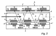
図2に図示の測定装置は、例えば、位相測定のために使用することができ、その場合、測定信号を参照するための参照信号を得る必要がある。本発明に拠れば、少なくとも1つの参照光源10および/又は11が、貫流測定セル1の励起側7に設けられ、その参照放射光R1,R2が貫流測定セル1を通過して反対側の測定側8に配置された光検出器6によって検出される。例えば、620nmの範囲の参照放射光R1を有する第1参照光源10と、780nmの範囲の参照放射光R2を有する第2参照光源11とを設けることができ、好ましくは、これらの両方が前記2つの部分から成る測定スリーブ2の励起側3に配置される。前記貫流測定セル1の励起側7の前記ミラー層9には、開口部14が設けられ、これらを通して前記参照放射光が貫流測定セル1に入ることができる。
The measuring device shown in FIG. 2 can be used, for example, for phase measurement, in which case it is necessary to obtain a reference signal for referring to the measurement signal. According to the invention, at least one
図1において、図2においても同様に、前記光源4と発光光センサ素子ST,SO,SGとの間に励起フィルタ12a,12b,12cが設けられ、更に、前記光源4も共通のフィルタ層12’に埋設することが可能である。前記光検出器6の入口側には測定フィルタ13a,13b,13cが設けられている。
1, similarly, excitation filters 12 a, 12 b, and 12 c are provided between the
前記光源4のLEDは、例えば、600nm未満、例えば425nm、の波長の励起放射光を放出するものとし、他方、前記発光光センサ素子ST,SO,SGの発光放射光は、600nm以上、例えば、780nmに近い波長範囲にあるものとすることができる。
The LED of the
以上をまとめると、本発明の測定装置の利点は以下の通りである。
* 光学構造が非常に単純である。
* 貫流測定セル1と測定スリーブ2とがフラット(平ら)な構造である。
* 光検出器を大型のものにすることが可能であるため信号強度が大きい。
* 測定スリーブ2の励起部3と測定部5とが空間的に分離されているので電気クロストーク(相互干渉)が無い(信号バックグランド(雑音)が最小)。
* サンプル(血液サンプル又はすすぎ用流体)の同定が信号強度を測定することによって行われる。
* 血液サンプル(ヘモグロビン含有量と酸素含有量)の同時光分析測定。
* 動脈pO2の並行測定。
In summary, the advantages of the measuring apparatus of the present invention are as follows.
* The optical structure is very simple.
* The once-through measurement cell 1 and the measurement sleeve 2 have a flat structure.
* The signal intensity is large because the photodetector can be made large.
* Since the
* The sample (blood sample or rinsing fluid) is identified by measuring the signal strength.
* Simultaneous photometric measurement of blood samples (hemoglobin content and oxygen content).
* Concurrent measurement of arterial pO 2.
Claims (14)
前記血液サンプルと接触させることが可能な少なくとも1つの発光−光センサ素子(ST,SO,SG)が内部に設けられた貫流測定セル(1)と、前記発光−光センサ素子を励起する少なくとも1つの光源(4)と、前記発光−光センサ素子から放出された発光放射光を受ける少なくとも1つの光検出器(6)と、を備え、前記光源(4)と前記光検出器(6)とが、互いに前記貫流測定セル(1)の反対側(7)(8)になるように配置されているものにおいて、
前記少なくとも1つの発光−光センサ素子(ST,SO,SG)は、前記貫流測定セル(1)の前記光源(4)に面する励起側(7)に配置され、前記光源(4)は、600nm未満の励起波長の励起放射光を放出し、そして、前記発光−光センサ素子(ST,SO,SG)の発光放射光は、600nm以上の波長範囲であり、これにより、前記励起放射光は、前記発光放射光よりも前記血液サンプルによって大きく吸収される測定装置。 A measuring device for measuring at least one parameter of a blood sample,
A flow-through measurement cell (1) in which at least one luminescence-light sensor element (ST, SO, SG) that can be brought into contact with the blood sample is provided, and at least one for exciting the luminescence-light sensor element. Two light sources (4), and at least one photodetector (6) that receives the emitted radiant light emitted from the luminescence-photosensor element, the light source (4) and the photodetector (6) , Are arranged so as to be on opposite sides (7) and (8) of the flow-through measurement cell (1).
The at least one emission-light sensor element (ST, SO, SG) is arranged on the excitation side (7) facing the light source (4) of the flow-through measurement cell (1), the light source (4) being emit excitation radiation of the excitation wavelength of 600nm less than, and the emission - emitting radiation light sensor elements (ST, SO, SG) is a wavelength range above 600nm, thereby, the excitation radiation Is a measuring device that is absorbed more greatly by the blood sample than the emitted radiation.
Applications Claiming Priority (3)
| Application Number | Priority Date | Filing Date | Title |
|---|---|---|---|
| AT0007909A AT507994B1 (en) | 2009-01-19 | 2009-01-19 | Measurement arrangement for determining at least one parameter of a sample liquor |
| ATA79/2009 | 2009-01-19 | ||
| PCT/EP2010/050239 WO2010081790A1 (en) | 2009-01-19 | 2010-01-12 | Measuring arrangement for determining at least one parameter of a blood sample |
Publications (2)
| Publication Number | Publication Date |
|---|---|
| JP2012515337A JP2012515337A (en) | 2012-07-05 |
| JP5459876B2 true JP5459876B2 (en) | 2014-04-02 |
Family
ID=42109781
Family Applications (1)
| Application Number | Title | Priority Date | Filing Date |
|---|---|---|---|
| JP2011545719A Expired - Fee Related JP5459876B2 (en) | 2009-01-19 | 2010-01-12 | Measuring device for measuring at least one parameter of a blood sample |
Country Status (16)
| Country | Link |
|---|---|
| US (1) | US8698103B2 (en) |
| EP (1) | EP2380003B1 (en) |
| JP (1) | JP5459876B2 (en) |
| CN (1) | CN102282455B (en) |
| AT (1) | AT507994B1 (en) |
| AU (1) | AU2010205741B2 (en) |
| BR (1) | BRPI1006880B1 (en) |
| CA (1) | CA2749050C (en) |
| DK (1) | DK2380003T3 (en) |
| ES (1) | ES2390842T3 (en) |
| IL (1) | IL213873A (en) |
| MY (1) | MY152230A (en) |
| PL (1) | PL2380003T3 (en) |
| RU (1) | RU2468355C1 (en) |
| SG (1) | SG172844A1 (en) |
| WO (1) | WO2010081790A1 (en) |
Families Citing this family (4)
| Publication number | Priority date | Publication date | Assignee | Title |
|---|---|---|---|---|
| DE102010038428A1 (en) * | 2010-07-26 | 2012-01-26 | Endress + Hauser Conducta Gesellschaft für Mess- und Regeltechnik mbH + Co. KG | Optical measuring system |
| PT106367B (en) * | 2012-06-06 | 2014-08-12 | Univ Do Minho | SYSTEM FOR DETERMINING THE BLOOD TYPE OF HUMANS AND RESPECT METHOD OF USE |
| DE102016115607A1 (en) | 2016-08-23 | 2018-03-01 | B. Braun Melsungen Ag | Measuring system with reduced crosstalk for measuring fluid parameters |
| SE542345C2 (en) | 2018-08-03 | 2020-04-14 | Redsense Medical Ab | Device for measuring a property of a measurement object by luminescence |
Family Cites Families (10)
| Publication number | Priority date | Publication date | Assignee | Title |
|---|---|---|---|---|
| CA1266996A (en) * | 1984-09-19 | 1990-03-27 | Stefan Brauer | Methods and apparatus for rapidly determining parameters of a sample medium |
| JPH03136637A (en) * | 1989-10-24 | 1991-06-11 | Nippon Koden Corp | Non-observing type blood component concentration measuring device |
| AT403745B (en) * | 1996-02-29 | 1998-05-25 | Avl Verbrennungskraft Messtech | MEASURING ARRANGEMENT WITH A TRANSPARENT ELEMENT FOR EXCITING AND MEASURING RADIATION |
| US6331438B1 (en) * | 1999-11-24 | 2001-12-18 | Iowa State University Research Foundation, Inc. | Optical sensors and multisensor arrays containing thin film electroluminescent devices |
| AT410600B (en) * | 1999-12-02 | 2003-06-25 | Hoffmann La Roche | MEASURING CHAMBER WITH LUMINESCENCE OPTICAL SENSOR ELEMENTS |
| US6379969B1 (en) | 2000-03-02 | 2002-04-30 | Agilent Technologies, Inc. | Optical sensor for sensing multiple analytes |
| RU2190208C2 (en) * | 2000-12-14 | 2002-09-27 | Государственный научно-исследовательский институт биологического приборостроения | Device measuring luminescence of biological specimens |
| US6632402B2 (en) | 2001-01-24 | 2003-10-14 | Ntc Technology Inc. | Oxygen monitoring apparatus |
| JP2003177097A (en) * | 2001-12-12 | 2003-06-27 | Mitsubishi Chemicals Corp | Chip for optical analysis |
| CN1985168B (en) * | 2004-05-14 | 2013-01-02 | 霍尼韦尔国际公司 | Portable sample analyzer with removable cartridge |
-
2009
- 2009-01-19 AT AT0007909A patent/AT507994B1/en not_active IP Right Cessation
-
2010
- 2010-01-12 EP EP10701116A patent/EP2380003B1/en active Active
- 2010-01-12 WO PCT/EP2010/050239 patent/WO2010081790A1/en active Application Filing
- 2010-01-12 MY MYPI2011003367 patent/MY152230A/en unknown
- 2010-01-12 SG SG2011048873A patent/SG172844A1/en unknown
- 2010-01-12 US US13/144,979 patent/US8698103B2/en active Active
- 2010-01-12 CA CA2749050A patent/CA2749050C/en active Active
- 2010-01-12 CN CN201080005452.9A patent/CN102282455B/en not_active Expired - Fee Related
- 2010-01-12 RU RU2011134658/04A patent/RU2468355C1/en active
- 2010-01-12 DK DK10701116.5T patent/DK2380003T3/en active
- 2010-01-12 BR BRPI1006880-5A patent/BRPI1006880B1/en not_active IP Right Cessation
- 2010-01-12 PL PL10701116T patent/PL2380003T3/en unknown
- 2010-01-12 AU AU2010205741A patent/AU2010205741B2/en not_active Ceased
- 2010-01-12 ES ES10701116T patent/ES2390842T3/en active Active
- 2010-01-12 JP JP2011545719A patent/JP5459876B2/en not_active Expired - Fee Related
-
2011
- 2011-06-30 IL IL213873A patent/IL213873A/en active IP Right Grant
Also Published As
| Publication number | Publication date |
|---|---|
| EP2380003B1 (en) | 2012-07-25 |
| SG172844A1 (en) | 2011-08-29 |
| EP2380003A1 (en) | 2011-10-26 |
| BRPI1006880A2 (en) | 2016-03-15 |
| CA2749050A1 (en) | 2010-07-22 |
| ES2390842T3 (en) | 2012-11-19 |
| AU2010205741A1 (en) | 2011-07-21 |
| US8698103B2 (en) | 2014-04-15 |
| US20120037816A1 (en) | 2012-02-16 |
| MY152230A (en) | 2014-09-15 |
| RU2468355C1 (en) | 2012-11-27 |
| CN102282455B (en) | 2015-04-15 |
| AU2010205741B2 (en) | 2013-04-18 |
| CN102282455A (en) | 2011-12-14 |
| AT507994A1 (en) | 2010-09-15 |
| BRPI1006880B1 (en) | 2020-03-10 |
| AT507994B1 (en) | 2011-05-15 |
| CA2749050C (en) | 2015-03-10 |
| JP2012515337A (en) | 2012-07-05 |
| WO2010081790A1 (en) | 2010-07-22 |
| DK2380003T3 (en) | 2012-09-10 |
| IL213873A0 (en) | 2011-07-31 |
| PL2380003T3 (en) | 2012-12-31 |
| IL213873A (en) | 2015-11-30 |
Similar Documents
| Publication | Publication Date | Title |
|---|---|---|
| JP5334846B2 (en) | Spectroscopic detector and method for determining blood and biomarker substances in liquid | |
| JP5695089B2 (en) | In particular, a measuring device and a measuring method for measuring blood glucose | |
| JP5683836B2 (en) | Method for detecting contaminants in optical measurement cuvettes | |
| JP4640797B2 (en) | Biomolecular interaction measuring apparatus and measuring method | |
| JP5501573B2 (en) | Oximeter | |
| RU2004123207A (en) | METHOD FOR ANALYSIS OF HEMOGLOBIN AND SYSTEM FOR ITS IMPLEMENTATION | |
| US20080180652A1 (en) | Test element analysis system | |
| JP5459876B2 (en) | Measuring device for measuring at least one parameter of a blood sample | |
| EP2535700A2 (en) | Device and system for the quantification of breath gases | |
| JP6467051B2 (en) | Pulse oximetry device and method of operating pulse oximetry device | |
| US8580199B2 (en) | Oxygen sensor and measuring method | |
| WO2006059672A1 (en) | Evanescent catheter system | |
| JP2013512450A5 (en) | ||
| KR100940310B1 (en) | Multi channel fluorescence detector | |
| JP6010434B2 (en) | Body fluid component analyzer and body fluid component analysis method | |
| WO2017010043A1 (en) | Functional water concentration sensor | |
| WO2008105435A1 (en) | Fluorescence detection system | |
| JP4923066B2 (en) | Immunoassay device, optical fiber used in immunoassay device, and method for performing immunoassay | |
| JP5096975B2 (en) | Gas detector | |
| JP2019017990A (en) | Density measurement module, dialysis device and density calculation method | |
| JPH09503856A (en) | Device for measuring the concentration of substances in blood | |
| US20120252131A1 (en) | Biological material analyzer and biological material analysis method | |
| CN218823928U (en) | Nucleic acid detector and fluorescence detection device thereof | |
| JP2021071465A (en) | Milk testing device |
Legal Events
| Date | Code | Title | Description |
|---|---|---|---|
| A621 | Written request for application examination |
Free format text: JAPANESE INTERMEDIATE CODE: A621 Effective date: 20120828 |
|
| A977 | Report on retrieval |
Free format text: JAPANESE INTERMEDIATE CODE: A971007 Effective date: 20130821 |
|
| A131 | Notification of reasons for refusal |
Free format text: JAPANESE INTERMEDIATE CODE: A131 Effective date: 20130822 |
|
| A521 | Request for written amendment filed |
Free format text: JAPANESE INTERMEDIATE CODE: A523 Effective date: 20131122 |
|
| TRDD | Decision of grant or rejection written | ||
| A01 | Written decision to grant a patent or to grant a registration (utility model) |
Free format text: JAPANESE INTERMEDIATE CODE: A01 Effective date: 20131219 |
|
| A61 | First payment of annual fees (during grant procedure) |
Free format text: JAPANESE INTERMEDIATE CODE: A61 Effective date: 20140110 |
|
| R150 | Certificate of patent or registration of utility model |
Free format text: JAPANESE INTERMEDIATE CODE: R150 Ref document number: 5459876 Country of ref document: JP Free format text: JAPANESE INTERMEDIATE CODE: R150 |
|
| R250 | Receipt of annual fees |
Free format text: JAPANESE INTERMEDIATE CODE: R250 |
|
| R250 | Receipt of annual fees |
Free format text: JAPANESE INTERMEDIATE CODE: R250 |
|
| R250 | Receipt of annual fees |
Free format text: JAPANESE INTERMEDIATE CODE: R250 |
|
| R250 | Receipt of annual fees |
Free format text: JAPANESE INTERMEDIATE CODE: R250 |
|
| R250 | Receipt of annual fees |
Free format text: JAPANESE INTERMEDIATE CODE: R250 |
|
| R250 | Receipt of annual fees |
Free format text: JAPANESE INTERMEDIATE CODE: R250 |
|
| LAPS | Cancellation because of no payment of annual fees |