JP5458472B2 - X-ray tube - Google Patents
X-ray tube Download PDFInfo
- Publication number
- JP5458472B2 JP5458472B2 JP2007072355A JP2007072355A JP5458472B2 JP 5458472 B2 JP5458472 B2 JP 5458472B2 JP 2007072355 A JP2007072355 A JP 2007072355A JP 2007072355 A JP2007072355 A JP 2007072355A JP 5458472 B2 JP5458472 B2 JP 5458472B2
- Authority
- JP
- Japan
- Prior art keywords
- anode
- electron
- electron source
- ray
- magnetic lens
- Prior art date
- Legal status (The legal status is an assumption and is not a legal conclusion. Google has not performed a legal analysis and makes no representation as to the accuracy of the status listed.)
- Expired - Fee Related
Links
Images


Description
本発明は、X線非破壊検査装置やX線分析措置などのX線源として用いられるX線管に関するものである。 The present invention relates to an X-ray tube used as an X-ray source for an X-ray non-destructive inspection apparatus or an X-ray analysis measure.
X線を利用した検査装置としては、X線顕微鏡、異物検査装置、蛍光X線分析装置などの各種の産業検査装置や、X線診断装置などの医療用X線装置が知られている。それら装置に用いられるX線源のうち、高空間分解能なものはマイクロフォーカスX線管と呼ばれており、その分解能は10μm以下である。 As an inspection apparatus using X-rays, various industrial inspection apparatuses such as an X-ray microscope, a foreign substance inspection apparatus, and a fluorescent X-ray analysis apparatus, and medical X-ray apparatuses such as an X-ray diagnostic apparatus are known. Among the X-ray sources used in these apparatuses, those having a high spatial resolution are called microfocus X-ray tubes, and the resolution is 10 μm or less.
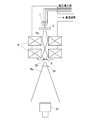
図3は、従来のX線検査装置の構成例を示している。本例でのX線検査装置は、電子源1から放出される電子をアノード3で加速後、電子光学系9により収束させた電子ビームReを衝突させ、タングステンなどの高融点金属の薄板でできたターゲット5上に微小なX線源23を得るようにしている。そして、X線源23から発生するX線Rxを用いて試料(被検査体)25の内部を拡大投影し、試料内部の微細構造を非破壊で透視検査するというものである。
FIG. 3 shows a configuration example of a conventional X-ray inspection apparatus. The X-ray inspection apparatus in this example is made of a thin plate of a refractory metal such as tungsten by accelerating electrons emitted from the
このような装置の空間分解能を決めているのはX線源の大きさで、X線源サイズ(焦点サイズ)が小さい方がボケ量が減って分解能が向上する。そのために、電子光学系9で電子ビームを小さく集束し、X線源サイズを小さくすることが研究されてきた。しかし、電子光学系の一般的な性質(収差)として、電子ビームを小さく集束させていくと電子ビーム量が減少することが知られている。したがって、X線量もそれに応じて減少するので、検査に時間がかかるという問題がある。
The spatial resolution of such an apparatus is determined by the size of the X-ray source. The smaller the X-ray source size (focal size), the smaller the blur amount and the higher the resolution. For this purpose, it has been studied to reduce the size of the X-ray source by converging the electron beam to a small size by the electron
電子ビームを小さく集束させても電子ビーム量を減少させない方法として、電子源の輝度を上げる方法がある。例えば、タングステンよりも高い電流密度が得られるLaB6(六ホウ化ランタン)のエミッタを用いる方法があるが、1μm以下で明るいX線源を実現するのは困難であった。 As a method for reducing the amount of electron beam even when the electron beam is focused small, there is a method for increasing the brightness of the electron source. For example, there is a method using a LaB6 (lanthanum hexaboride) emitter that can obtain a higher current density than tungsten, but it has been difficult to realize a bright X-ray source of 1 μm or less.
さらに、高分解能で明るいX線源を実現するため、LaB6よりも高い電流密度が得られるショットキーエミッタ等の電界放射電子源を用いたものが研究されている。しかし、ショットキーエミッタを用いてX線管で必要とされる大電流を流そうとすると、ショットキーエミッタはLaB6よりも電子銃の球面収差の影響が大きいので、高分解能を得るには工夫が必要である。 Furthermore, in order to realize a high-resolution and bright X-ray source, a device using a field emission electron source such as a Schottky emitter capable of obtaining a higher current density than LaB6 has been studied. However, if a large current required for an X-ray tube is made to flow using a Schottky emitter, the Schottky emitter is more affected by the spherical aberration of the electron gun than LaB6. is necessary.
ここで球面収差とは、レンズの中心部を通る電子ビームとレンズの周辺部を通る電子ビームとで集束する点が異なることであり、ボケの原因の1つである。球面収差を小さくするためには、レンズの周辺部を通る電子ビームを中心部に集める必要があり、磁場重畳型レンズを用いる方法が知られている。磁場重畳レンズを用いれば、電流密度も高くなるが、レンズだけでは限界もある。 Here, the spherical aberration, a point focused by the electron beam through the peripheral portion of the electron beam and the lens passing through the center portion of the lens is not less different, is one of the causes of blurring. In order to reduce the spherical aberration, it is necessary to collect the electron beam passing through the periphery of the lens at the center, and a method using a magnetic field superposition type lens is known. If a magnetic field superimposing lens is used, the current density is increased, but there is a limit to the lens alone.
このようなX線顕微鏡検査装置として、図4に示すような電子銃1の電子発生部近傍に磁界発生部を有する磁界重畳レンズ11を用いる方法が開示されている(特許文献1、2参照。)。
As such an X-ray microscope inspection apparatus, a method using a magnetic field
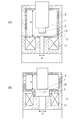
また、図5(A),(B)に開示されている概略図は図4に示した方法を具現化した例で、「電子源部(アノード3を含む電子源1)の電子発生部の近傍に、磁界重畳レンズ11を配置し、少なくとも電子発生部から電子加速手段の構成要素であるアノードに至るまで、電子源1が作る電界に磁界重畳レンズ11が作る磁界を重畳させて、電子をアノードで加速しながら集束させる構成」とすることで、収差の影響を低減させている(特許文献1、2参照。)。
The schematic diagrams disclosed in FIGS. 5A and 5B are examples embodying the method shown in FIG. 4, and “the electron generation part of the electron source part (
しかし、電子銃1と磁界重畳レンズ11の距離が近くなるために電子源部の耐電圧が低下し、X線ターゲット5に対して高管電圧の電子ビームを照射することが困難になり、X線管用の電子銃として利用することが困難になる。また、加速のためのアノードが明示されておらず、耐電圧がどの程度あるのか不明である。
また、磁界レンズ11のギャップ長s’とボア径b’を大きくとることで装置が大型化する上、レンズの磁界発生効率が悪化し、磁界回路のコイルを大型化する必要があり、アンペアターンは極端に大きくなり、コイルからの発熱が増大し、その対策として冷却機構が必要になる。
However, since the distance between the
Further, by increasing the gap length s 'and the bore diameter b' of the
ショットキーエミッタを用いてX線管で必要とされる大電流を得ようとするときの、電子源部の収差による空間分解能の制限を改善する為の、図4、図5(A),(B)に開示されている方法では、電子顕微鏡などで用いられる特殊な形状の磁界レンズを用いるため、電子源室のスペースが限定され、高電圧となる電子ビームエミッタと電子源室との間の耐電圧が低下し、X線管用の電子銃として利用することが困難になってしまう。 4A, 4B, 5A, 5A, 5A, 5A, 5A, and 5B for improving the spatial resolution limitation due to the aberration of the electron source portion when the Schottky emitter is used to obtain a large current required for the X-ray tube. In the method disclosed in B), a magnetic lens having a special shape used in an electron microscope or the like is used, so that the space of the electron source chamber is limited, and the space between the electron beam emitter and the electron source chamber that becomes a high voltage is limited. The withstand voltage is lowered, making it difficult to use as an electron gun for an X-ray tube.
本発明は、電子源部の耐電圧を低下させることなく電子源部の収差を低減させることができるX線管を提供することを目的とする。 An object of this invention is to provide the X-ray tube which can reduce the aberration of an electron source part, without reducing the withstand voltage of an electron source part.
本発明のX線管は、電子ビームを放出する電子源、電子源から放出された電子ビームを加速するアノード、及びアノードによって加速された電子ビームが照射されるX線ターゲットが真空系内に配置され、電子ビームをX線ターゲット上に集束させる電子光学系を備えている。その上、電子光学系の一部である磁界レンズは真空系の外側に配置し、磁界を電子源とX線ターゲットとの間に発生させ、電子ビームを集束させている。この磁界レンズのヨークの上端面とX線ターゲットの間にアノードの電子入射側の面を配置していることを特徴としている。 X-ray tube of the present invention, an electron source for emitting an electron beam, disposed anode, and X-ray target into the vacuum system the electron beam accelerated by the anode is irradiated to accelerate the emitted electron beam from the electron source And an electron optical system for focusing the electron beam on the X-ray target. In addition, a magnetic lens that is a part of the electron optical system is disposed outside the vacuum system, and a magnetic field is generated between the electron source and the X-ray target to focus the electron beam . The surface of the anode on the electron incident side is arranged between the upper end surface of the yoke of the magnetic lens and the X-ray target.
なお、磁界レンズには、ギャップ長sとボア径bが大きくない標準的なもの(例えばs=10mm、b=20mm)を用いることができる。 As the magnetic lens, a standard lens (for example, s = 10 mm, b = 20 mm) in which the gap length s and the bore diameter b are not large can be used.
アノードの電子入射側の面は磁界レンズのギャップの下端よりも電子源側に配置することが好ましい。 The surface on the electron incident side of the anode is preferably disposed closer to the electron source than the lower end of the gap of the magnetic lens.
最も良い形態の一つは、アノードの電子入射側の面が磁界レンズのヨークの上端面とほぼ同一面上に配置することである。 One of the best modes is that the surface on the electron incident side of the anode is arranged on the same plane as the upper end surface of the yoke of the magnetic lens.
さらに、電界レンズ作用を生じさせるためには等電位線を曲げる必要があるので、アノードは磁界レンズの内径よりも小さく、かつ、電子源方向に凸型となっていることが好ましい。 Furthermore, since it is necessary to bend the equipotential lines in order to generate the electric field lens action, it is preferable that the anode is smaller than the inner diameter of the magnetic lens and is convex toward the electron source.
さらに、電界作用を強めるために、凸型のアノードの外径は電子源からアノードまでの距離の50〜100%であることが好ましい。 Furthermore, in order to strengthen the electric field effect, the outer diameter of the convex anode is preferably 50 to 100% of the distance from the electron source to the anode.
本発明のX線管は、電子源、アノード及びX線ターゲットを真空系内に配置し、真空系の外側で電子源とX線ターゲットとの間には、磁界を発生させる磁界レンズを配置し、アノードは磁界レンズのヨークの上端面と同一面上又はX線ターゲット側に配置するようにしたので、アノードと光源をより近づけることができ、X線管の管電圧を高くすることが可能になる。 In the X-ray tube of the present invention, an electron source, an anode and an X-ray target are arranged in a vacuum system, and a magnetic lens for generating a magnetic field is arranged between the electron source and the X-ray target outside the vacuum system. Since the anode is arranged on the same plane as the upper end surface of the yoke of the magnetic lens or on the X-ray target side, the anode and the light source can be brought closer, and the tube voltage of the X-ray tube can be increased. Become.
アノードをギャップの下端よりも電子源側に配置することで、電子源部の収差を低減させるので、高分解能なX線管用の電子銃として利用することが可能となる。 By disposing the anode closer to the electron source than the lower end of the gap, the aberration of the electron source is reduced, so that it can be used as an electron gun for a high resolution X-ray tube.
磁界レンズのヨーク上端面とアノードの電子入射側の面とが同一平面上に配置されるようにすれば、さらに収差が低減される。 If the upper end surface of the yoke of the magnetic lens and the surface on the electron incident side of the anode are arranged on the same plane, the aberration is further reduced.
アノードを磁界レンズの内径よりも小さく、かつ、電子源方向に凸型となっているようにすれば、アノード近傍での等電位線を凸型形状に沿って曲げた電界レンズの集束作用により、ターゲット電流を増加させることができる。 If the anode is smaller than the inner diameter of the magnetic lens and is convex toward the electron source, the focusing action of the electric field lens in which the equipotential lines near the anode are bent along the convex shape, The target current can be increased.
さらに、アノードの外径を小さくすると、電界レンズ効果が高くなるので、ターゲット電流をより増加させることができる。 Furthermore, if the outer diameter of the anode is reduced, the electric field lens effect is enhanced, so that the target current can be further increased.
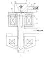
図1は、本発明のX線管の概略断面図である。
真空系内には、電子ビームを放出する電子源1、アノード3、X線ターゲット5が配置されている。真空系の外には、磁界レンズ11と磁界レンズ9が配置されている。図1は、真空排気特性が良い差動排気で構成した真空系を例示している。
FIG. 1 is a schematic sectional view of an X-ray tube of the present invention.
In the vacuum system, an
負の高電圧に維持された電子源1から放出された電子ビームReは、接地電位との電位差で加速される。実施例では、真空容器とアノード3が接地電位にあり、アノード3の中心にある孔(アパーチャー7)を通って、X線ターゲット5に衝突してX線を発生する。この時、真空系の外に設置された磁界レンズ11と磁界レンズ9により、電子ビームReをX線ターゲット5上で集束させることで、微小なX線源とすることができる。
The electron beam Re emitted from the
電子源1は、エミッタと電極から構成されている。エミッタとしては、タングステンフィラメント、LaB6、CeB6を使ってもよいが、ショットキーエミッターが最適である。電極は、エミッタからの電子を抑制したり、エミッタから電子を引き出したりする働きを持つ。
The
100kVぐらいの高エネルギーのX線を発生するためには、電子源1を−100kVに維持し、接地電位との間で加速する必要がある。図1ではアノード3と真空内壁とが接地電位にある。したがって、電子源1とこれらの間の耐電圧は100kV必要となる。真空内壁と電子源1の間の耐電圧が100kV丁度であるとすると、アノード3は真空内壁とほぼ同じ距離にあれば、電子源1とアノード3の間の耐電圧も100kVであり、図1の本実施例では、磁界レンズ11のヨーク上端面13とアノード3の上端面とが同一平面上に配置されるように構成している。
In order to generate high energy X-rays of about 100 kV, the
前記真空内壁の内、電子源1と磁界レンズの間にある真空内壁は電子源1に近づけた方が有利である。なぜならば、磁界レンズは電子源1に近づける方が集束性が向上するが、磁界レンズは真空外に置かれているためである。また、アノード3は、電子源1に近づける方が集束性が向上するからである。
Of the vacuum inner walls, it is advantageous that the vacuum inner wall between the
従来技術の構成を示した図5においては、電子源1と磁界レンズ11については図示されており、磁界レンズによる性能向上が見込まれる。しかし、アノード3が示されておらず、アノード3による性能向上は明示されていない。
In FIG. 5 showing the configuration of the prior art, the
電子源1とアノード3の間の耐電圧をさらに向上させて高エネルギーのX線を発生させるためには、耐電圧を向上させる必要がある。電子源1に最も近いのはアノード3であるから、アノード3を遠ざければ耐圧が向上する。
また、アノード3は磁界レンズギャップの下端よりも電子源1に近い位置にあれば、性能はほぼ変わらない。
In order to further improve the withstand voltage between the
If the
したがって、アノード3は磁界レンズ11のヨークの上端面13と同一面上又はX線ターゲット側で、かつ、磁界レンズ11のギャップsの下端15よりも電子源1側に配置されるのがよい。
Therefore, the
上記の実施例の説明では、アノード3は磁界レンズ11のギャップsの下端15よりも電子源1側に配置されているようにしているが、アノード3を磁界レンズの主面17よりも電子源1側に配置してもよい。ここで主面17とは、磁界レンズ中で電子ビームが屈折する面のことである。
In the description of the above embodiment, the
アノード3から電子源1までの距離が近づくことで電子銃部の収差が改善し、より良好な収束性能を得ることが可能となる。
As the distance from the
図2は図1のアノード付近を拡大した模式図で、第2の実施例を説明している。
第2の実施例の特徴である凸型形状アノード3の中心には直径1mm程度のアパーチャー7が設けられており、エミッタ19から発せられた電子ビームReが通過するようになっている。電子ビームの幅をc、電子源から発せられた電子ビームReがアノード3を通過するまでの距離をaとした場合、アノード3の外径は、電子源1からアノード3までの距離aの50〜100%程度が望ましい。
FIG. 2 is an enlarged schematic view of the vicinity of the anode in FIG. 1 and illustrates the second embodiment.
An
アノード3のエミッタ19側は凸型になっているため、エミッタ19とアノード3間の等電位線21はアノード3の凸型形状に沿うように曲げられ、電子源1とアノード3の間の電界レンズ作用を強めるので、電子ビームReをより集束させることができる。したがって、電流密度をより高くでき、同一のアパーチャー径でもより多くの電流をターゲットに照射することもできるので、より多くのX線を発生させられる。
Since the
図2の構成では電子源1とアノード3の間の電界に、磁界レンズ11による磁界を重畳させることができ、電子をアノード3で加速しながら集束させられるので、磁界レンズの収差の影響を低減させることができ、微小なX線源とすることができる。
In the configuration of FIG. 2, the magnetic field by the
従来例と比較して、本発明では標準的な磁界レンズを用いるので、
磁気回路に大電流を流す必要がなくなり、コイルからの発熱が大きく冷却機構を付加して装置が大きくなるということもない。また、電子源室のスペースが限定されることもないため、電子ビームエミッタと電子源室との間の耐電圧を高くすることができる。したがって、小型で高管電圧の明るいX線管を実現することができる。
Compared to the conventional example, the present invention uses a standard magnetic lens, so
It is no longer necessary to pass a large current through the magnetic circuit, and heat generation from the coil is large, and a cooling mechanism is added to increase the size of the device. Moreover, since the space of the electron source chamber is not limited, the withstand voltage between the electron beam emitter and the electron source chamber can be increased. Accordingly, it is possible to realize a small X-ray tube with a high tube voltage.
本発明はX線非破壊検査装置やX線分析装置などのX線源として用いられる高性能なX線管に利用することができる。 The present invention can be used for a high-performance X-ray tube used as an X-ray source such as an X-ray nondestructive inspection apparatus and an X-ray analyzer.
1 電子源部
2 真空内壁
3 アノード
5 X線ターゲット
7 アパーチャー
9 電子光学系
11 磁界レンズ
13 ヨークの上端面
15 ギャップの下端
17 主面
19 エミッタ
21 等電位線
DESCRIPTION OF
Claims (3)
前記電子光学系は磁界を前記電子源とX線ターゲットとの間に発生させる磁界レンズを前記真空系の外側に備え、
前記磁界レンズは前記電子源に近い側に配置された第1磁界レンズとそれより遠い側に配置された第2磁界レンズを含んでおり、
前記第1磁界レンズはその全体が前記電子源よりもX線ターゲット側に配置され、前記アノードの側方にギャップをもったものであり、
前記アノードの電子入射側の面は、前記第1磁界レンズのヨークが磁界を発生する部分の上端面と同一面上、又は第1磁界レンズの前記上端面と前記ギャップの下端との間に配置されていることにより、前記第1磁界レンズは前記電子源と前記アノードとの間の電界に磁界を重畳させることを特徴とするX線管。 An electron source for emitting an electron beam, an anode for accelerating the electron beam emitted from the electron source, and an X-ray target irradiated with the electron beam accelerated by the anode are arranged from above to below in the vacuum system An X-ray tube comprising an electron optical system for focusing the electron beam on an X-ray target;
The electron optical system includes a magnetic lens that generates a magnetic field between the electron source and the X-ray target outside the vacuum system,
The magnetic lens includes a first magnetic lens disposed on a side closer to the electron source and a second magnetic lens disposed on a side farther from the first magnetic lens.
The entire first magnetic lens is disposed closer to the X-ray target than the electron source, and has a gap on the side of the anode.
The surface of the anode on the electron incident side is disposed on the same plane as the upper end surface of the portion where the yoke of the first magnetic lens generates a magnetic field , or between the upper end surface of the first magnetic lens and the lower end of the gap. Thus , the first magnetic lens causes the magnetic field to be superimposed on the electric field between the electron source and the anode.
Priority Applications (1)
| Application Number | Priority Date | Filing Date | Title |
|---|---|---|---|
| JP2007072355A JP5458472B2 (en) | 2007-03-20 | 2007-03-20 | X-ray tube |
Applications Claiming Priority (1)
| Application Number | Priority Date | Filing Date | Title |
|---|---|---|---|
| JP2007072355A JP5458472B2 (en) | 2007-03-20 | 2007-03-20 | X-ray tube |
Publications (3)
| Publication Number | Publication Date |
|---|---|
| JP2008234981A JP2008234981A (en) | 2008-10-02 |
| JP2008234981A5 JP2008234981A5 (en) | 2010-04-30 |
| JP5458472B2 true JP5458472B2 (en) | 2014-04-02 |
Family
ID=39907554
Family Applications (1)
| Application Number | Title | Priority Date | Filing Date |
|---|---|---|---|
| JP2007072355A Expired - Fee Related JP5458472B2 (en) | 2007-03-20 | 2007-03-20 | X-ray tube |
Country Status (1)
| Country | Link |
|---|---|
| JP (1) | JP5458472B2 (en) |
Families Citing this family (5)
| Publication number | Priority date | Publication date | Assignee | Title |
|---|---|---|---|---|
| WO2014064748A1 (en) | 2012-10-22 | 2014-05-01 | 株式会社島津製作所 | X-ray tube device |
| JP6218403B2 (en) * | 2013-03-15 | 2017-10-25 | 株式会社マーストーケンソリューション | X-ray tube equipped with a field emission electron gun and X-ray inspection apparatus using the same |
| US9984847B2 (en) | 2013-03-15 | 2018-05-29 | Mars Tohken Solution Co., Ltd. | Open-type X-ray tube comprising field emission type electron gun and X-ray inspection apparatus using the same |
| CN105140088B (en) * | 2015-07-24 | 2017-10-17 | 北京航空航天大学 | The focusing arrangement and its application method of big beam deflection target practice X-ray source with microbeam |
| JP6705507B2 (en) * | 2016-10-07 | 2020-06-03 | 株式会社ニコン | Charged particle beam device, electron beam generator, X-ray source, X-ray device, and structure manufacturing method |
Family Cites Families (5)
| Publication number | Priority date | Publication date | Assignee | Title |
|---|---|---|---|---|
| US3141993A (en) * | 1959-12-24 | 1964-07-21 | Zeiss Jena Veb Carl | Very fine beam electron gun |
| US5044001A (en) * | 1987-12-07 | 1991-08-27 | Nanod Ynamics, Inc. | Method and apparatus for investigating materials with X-rays |
| JP4306110B2 (en) * | 2000-10-04 | 2009-07-29 | 株式会社島津製作所 | Open X-ray tube |
| JP4029209B2 (en) * | 2002-10-17 | 2008-01-09 | 株式会社東研 | High resolution X-ray microscope |
| US7428298B2 (en) * | 2005-03-31 | 2008-09-23 | Moxtek, Inc. | Magnetic head for X-ray source |
-
2007
- 2007-03-20 JP JP2007072355A patent/JP5458472B2/en not_active Expired - Fee Related
Also Published As
| Publication number | Publication date |
|---|---|
| JP2008234981A (en) | 2008-10-02 |
Similar Documents
| Publication | Publication Date | Title |
|---|---|---|
| US7218703B2 (en) | X-ray microscopic inspection apparatus | |
| JP2007335125A (en) | Electron beam device | |
| US20100046716A1 (en) | X-ray tube with backscatter protection | |
| JP6218403B2 (en) | X-ray tube equipped with a field emission electron gun and X-ray inspection apparatus using the same | |
| JP2007103316A (en) | X-ray tube | |
| JP5458472B2 (en) | X-ray tube | |
| JP6312387B2 (en) | Particle beam device and method of operating particle beam device | |
| JP4029209B2 (en) | High resolution X-ray microscope | |
| JP2010033992A (en) | X-ray tube and x-ray analysis device | |
| JP2017135082A (en) | X-ray generation tube, x-ray generation device, and x-ray imaging system | |
| KR102195101B1 (en) | X-ray tube | |
| US9524845B2 (en) | X-ray tube cathode with magnetic electron beam steering | |
| JP2002324510A (en) | Scanning electron microscope | |
| JP4914178B2 (en) | Schottky electron gun and charged particle beam apparatus equipped with Schottky electron gun | |
| JP2012142129A (en) | Soft x-ray source | |
| JP4370576B2 (en) | X-ray generator | |
| JP2009076447A (en) | Scanning electron microscope | |
| JP7458384B2 (en) | Electron gun and charged particle beam device equipped with an electron gun | |
| JP2005093106A (en) | Scanning electron microscope | |
| JP5993356B2 (en) | Scanning electron microscope | |
| JP5210088B2 (en) | Electron beam equipment | |
| JP7367165B2 (en) | X-ray generator tube, X-ray generator and X-ray imaging system | |
| JP6178296B2 (en) | Electron beam emission tube | |
| CN217444331U (en) | Cold cathode X-ray tube and X-ray generator | |
| JP2005327497A (en) | X-ray generator |
Legal Events
| Date | Code | Title | Description |
|---|---|---|---|
| A521 | Written amendment |
Free format text: JAPANESE INTERMEDIATE CODE: A523 Effective date: 20100315 |
|
| A621 | Written request for application examination |
Free format text: JAPANESE INTERMEDIATE CODE: A621 Effective date: 20100315 |
|
| A977 | Report on retrieval |
Free format text: JAPANESE INTERMEDIATE CODE: A971007 Effective date: 20111227 |
|
| A131 | Notification of reasons for refusal |
Free format text: JAPANESE INTERMEDIATE CODE: A131 Effective date: 20120327 |
|
| A521 | Written amendment |
Free format text: JAPANESE INTERMEDIATE CODE: A523 Effective date: 20120528 |
|
| A131 | Notification of reasons for refusal |
Free format text: JAPANESE INTERMEDIATE CODE: A131 Effective date: 20130507 |
|
| A521 | Written amendment |
Free format text: JAPANESE INTERMEDIATE CODE: A523 Effective date: 20130701 |
|
| TRDD | Decision of grant or rejection written | ||
| A01 | Written decision to grant a patent or to grant a registration (utility model) |
Free format text: JAPANESE INTERMEDIATE CODE: A01 Effective date: 20131217 |
|
| A61 | First payment of annual fees (during grant procedure) |
Free format text: JAPANESE INTERMEDIATE CODE: A61 Effective date: 20131230 |
|
| R151 | Written notification of patent or utility model registration |
Ref document number: 5458472 Country of ref document: JP Free format text: JAPANESE INTERMEDIATE CODE: R151 |
|
| LAPS | Cancellation because of no payment of annual fees |