JP5456232B2 - Electrostatically treated phenolic resin material and method - Google Patents
Electrostatically treated phenolic resin material and method Download PDFInfo
- Publication number
- JP5456232B2 JP5456232B2 JP2006509201A JP2006509201A JP5456232B2 JP 5456232 B2 JP5456232 B2 JP 5456232B2 JP 2006509201 A JP2006509201 A JP 2006509201A JP 2006509201 A JP2006509201 A JP 2006509201A JP 5456232 B2 JP5456232 B2 JP 5456232B2
- Authority
- JP
- Japan
- Prior art keywords
- carbonized
- phenolic resin
- activated
- electrospun
- fiber
- Prior art date
- Legal status (The legal status is an assumption and is not a legal conclusion. Google has not performed a legal analysis and makes no representation as to the accuracy of the status listed.)
- Expired - Fee Related
Links
Images


Classifications
-
- D—TEXTILES; PAPER
- D01—NATURAL OR MAN-MADE THREADS OR FIBRES; SPINNING
- D01F—CHEMICAL FEATURES IN THE MANUFACTURE OF ARTIFICIAL FILAMENTS, THREADS, FIBRES, BRISTLES OR RIBBONS; APPARATUS SPECIALLY ADAPTED FOR THE MANUFACTURE OF CARBON FILAMENTS
- D01F9/00—Artificial filaments or the like of other substances; Manufacture thereof; Apparatus specially adapted for the manufacture of carbon filaments
- D01F9/08—Artificial filaments or the like of other substances; Manufacture thereof; Apparatus specially adapted for the manufacture of carbon filaments of inorganic material
- D01F9/12—Carbon filaments; Apparatus specially adapted for the manufacture thereof
- D01F9/14—Carbon filaments; Apparatus specially adapted for the manufacture thereof by decomposition of organic filaments
- D01F9/20—Carbon filaments; Apparatus specially adapted for the manufacture thereof by decomposition of organic filaments from polyaddition, polycondensation or polymerisation products
- D01F9/24—Carbon filaments; Apparatus specially adapted for the manufacture thereof by decomposition of organic filaments from polyaddition, polycondensation or polymerisation products from macromolecular compounds obtained otherwise than by reactions only involving carbon-to-carbon unsaturated bonds
-
- A—HUMAN NECESSITIES
- A24—TOBACCO; CIGARS; CIGARETTES; SIMULATED SMOKING DEVICES; SMOKERS' REQUISITES
- A24D—CIGARS; CIGARETTES; TOBACCO SMOKE FILTERS; MOUTHPIECES FOR CIGARS OR CIGARETTES; MANUFACTURE OF TOBACCO SMOKE FILTERS OR MOUTHPIECES
- A24D3/00—Tobacco smoke filters, e.g. filter-tips, filtering inserts; Filters specially adapted for simulated smoking devices; Mouthpieces for cigars or cigarettes
- A24D3/06—Use of materials for tobacco smoke filters
- A24D3/16—Use of materials for tobacco smoke filters of inorganic materials
- A24D3/163—Carbon
-
- C—CHEMISTRY; METALLURGY
- C01—INORGANIC CHEMISTRY
- C01B—NON-METALLIC ELEMENTS; COMPOUNDS THEREOF; METALLOIDS OR COMPOUNDS THEREOF NOT COVERED BY SUBCLASS C01C
- C01B32/00—Carbon; Compounds thereof
- C01B32/30—Active carbon
-
- C—CHEMISTRY; METALLURGY
- C01—INORGANIC CHEMISTRY
- C01B—NON-METALLIC ELEMENTS; COMPOUNDS THEREOF; METALLOIDS OR COMPOUNDS THEREOF NOT COVERED BY SUBCLASS C01C
- C01B32/00—Carbon; Compounds thereof
- C01B32/30—Active carbon
- C01B32/312—Preparation
- C01B32/318—Preparation characterised by the starting materials
-
- D—TEXTILES; PAPER
- D01—NATURAL OR MAN-MADE THREADS OR FIBRES; SPINNING
- D01D—MECHANICAL METHODS OR APPARATUS IN THE MANUFACTURE OF ARTIFICIAL FILAMENTS, THREADS, FIBRES, BRISTLES OR RIBBONS
- D01D5/00—Formation of filaments, threads, or the like
- D01D5/0007—Electro-spinning
-
- D—TEXTILES; PAPER
- D01—NATURAL OR MAN-MADE THREADS OR FIBRES; SPINNING
- D01D—MECHANICAL METHODS OR APPARATUS IN THE MANUFACTURE OF ARTIFICIAL FILAMENTS, THREADS, FIBRES, BRISTLES OR RIBBONS
- D01D5/00—Formation of filaments, threads, or the like
- D01D5/0007—Electro-spinning
- D01D5/0015—Electro-spinning characterised by the initial state of the material
- D01D5/003—Electro-spinning characterised by the initial state of the material the material being a polymer solution or dispersion
-
- D—TEXTILES; PAPER
- D01—NATURAL OR MAN-MADE THREADS OR FIBRES; SPINNING
- D01F—CHEMICAL FEATURES IN THE MANUFACTURE OF ARTIFICIAL FILAMENTS, THREADS, FIBRES, BRISTLES OR RIBBONS; APPARATUS SPECIALLY ADAPTED FOR THE MANUFACTURE OF CARBON FILAMENTS
- D01F1/00—General methods for the manufacture of artificial filaments or the like
- D01F1/02—Addition of substances to the spinning solution or to the melt
- D01F1/10—Other agents for modifying properties
-
- D—TEXTILES; PAPER
- D01—NATURAL OR MAN-MADE THREADS OR FIBRES; SPINNING
- D01F—CHEMICAL FEATURES IN THE MANUFACTURE OF ARTIFICIAL FILAMENTS, THREADS, FIBRES, BRISTLES OR RIBBONS; APPARATUS SPECIALLY ADAPTED FOR THE MANUFACTURE OF CARBON FILAMENTS
- D01F6/00—Monocomponent artificial filaments or the like of synthetic polymers; Manufacture thereof
- D01F6/44—Monocomponent artificial filaments or the like of synthetic polymers; Manufacture thereof from mixtures of polymers obtained by reactions only involving carbon-to-carbon unsaturated bonds as major constituent with other polymers or low-molecular-weight compounds
- D01F6/50—Monocomponent artificial filaments or the like of synthetic polymers; Manufacture thereof from mixtures of polymers obtained by reactions only involving carbon-to-carbon unsaturated bonds as major constituent with other polymers or low-molecular-weight compounds of polyalcohols, polyacetals or polyketals
-
- D—TEXTILES; PAPER
- D01—NATURAL OR MAN-MADE THREADS OR FIBRES; SPINNING
- D01F—CHEMICAL FEATURES IN THE MANUFACTURE OF ARTIFICIAL FILAMENTS, THREADS, FIBRES, BRISTLES OR RIBBONS; APPARATUS SPECIALLY ADAPTED FOR THE MANUFACTURE OF CARBON FILAMENTS
- D01F6/00—Monocomponent artificial filaments or the like of synthetic polymers; Manufacture thereof
- D01F6/58—Monocomponent artificial filaments or the like of synthetic polymers; Manufacture thereof from homopolycondensation products
- D01F6/76—Monocomponent artificial filaments or the like of synthetic polymers; Manufacture thereof from homopolycondensation products from other polycondensation products
Landscapes
- Chemical & Material Sciences (AREA)
- Engineering & Computer Science (AREA)
- Textile Engineering (AREA)
- Organic Chemistry (AREA)
- Chemical Kinetics & Catalysis (AREA)
- General Chemical & Material Sciences (AREA)
- Inorganic Chemistry (AREA)
- Mechanical Engineering (AREA)
- Materials Engineering (AREA)
- Manufacturing & Machinery (AREA)
- Dispersion Chemistry (AREA)
- Carbon And Carbon Compounds (AREA)
- Artificial Filaments (AREA)
- Cigarettes, Filters, And Manufacturing Of Filters (AREA)
- Processes Of Treating Macromolecular Substances (AREA)
- Inorganic Fibers (AREA)
- Manufacture Of Tobacco Products (AREA)
- Manufacture Of Porous Articles, And Recovery And Treatment Of Waste Products (AREA)
- Spinning Methods And Devices For Manufacturing Artificial Fibers (AREA)
- Compositions Of Macromolecular Compounds (AREA)
- Electric Double-Layer Capacitors Or The Like (AREA)
Description
特性が制御され、または特別な構造特性を有する人工材料は、生物医学、軍事、濾過、触媒、光学および電子工学の分野の用途に供されてきた。従って、研究者は、この十年にわたって新規な製造技術の開発に傾注してきた。特に、ナノサイズの材料の基本的理解および開発については、ますます人気のある領域になってきた。 Artificial materials with controlled properties or special structural properties have been subjected to applications in the fields of biomedicine, military, filtration, catalysis, optics and electronics. Researchers have therefore focused their efforts on developing new manufacturing technologies over the last decade. In particular, the basic understanding and development of nano-sized materials has become an increasingly popular area.
ナノメートル(nm)とは1mの10億分の1、即ち、10-9mである。ナノテクノロジーとは、約1nm乃至約100nmのスケールの材料、デバイスおよびシステムに関する研究ならびに利用のことである。このサイズの材料に関心が持たれる1つの理由は、強度、疲労などの材料の重要な特性の一部が非線形的かつ個別に材料の微細構造に基づいていることが発見されたからである。ナノテクノロジーへの関心を支えている別の原動力となっているのは、デバイスを小型化、軽量化、強化および高速化したいという要望である。もし研究者がnmのスケールで原子を操作することができるようになれば、その結果、コンピュータ処理、エレクトロニクス、エネルギー、材料設計、製造、医学、その他数多くの分野に革命がもたらされるであろうと信じる専門家もいる。 Nanometer (nm) is 1 billionth of 1 m, that is, 10 -9 m. Nanotechnology is the research and utilization of materials, devices and systems with scales of about 1 nm to about 100 nm. One reason for interest in materials of this size is that it has been discovered that some of the important properties of the material, such as strength, fatigue, etc., are nonlinear and individually based on the microstructure of the material. Another driving force behind the interest in nanotechnology is the desire to make devices smaller, lighter, stronger and faster. I believe that if researchers are able to manipulate atoms at the nm scale, this will revolutionize computer processing, electronics, energy, materials design, manufacturing, medicine, and many other fields There are also experts.
静電紡糸は、ナノメートル・スケールの直径を有する繊維を生産するために用いることができる従来にない繊維製造技術である。また、これはナノ繊維より大きい(約0.1μm乃至数10μmの)直径を有するマイクロ繊維の生産にも有用である。静電紡糸の大部分の研究開発では、この技術が繊維製造の最終的な方法であると考えられてきた。例えば、研究者は、種々の重合体系(system)について「曳糸性(spinnability)」を検討し、繊維の表面および容積の特性を明らかにし、その形状を調べ、作業変数の系統的な検討を行うことにより、この方法の基本的な理解を向上させ、製造繊維を改善してきた。しかしながら、静電処理をその後の処理工程の先行工程として用いる領域については全くと言ってよいほど何も検討されてこなかった。 Electrospinning is an unprecedented fiber manufacturing technique that can be used to produce fibers having nanometer scale diameters. It is also useful for the production of microfibers having a diameter larger than nanofibers (about 0.1 μm to several tens of μm). In most research and development of electrospinning, this technology has been considered the final method of fiber production. For example, researchers have studied “spinnability” for various polymer systems, elucidated the surface and volume characteristics of fibers, examined their shapes, and systematically examined working variables. By doing so, the basic understanding of this method has been improved and the manufactured fibers have been improved. However, nothing has been studied about the area where electrostatic treatment is used as a preceding step of the subsequent processing step.
これまで開発が進められてきたにもかかわらず、他の手段では得ることができない特性が向上した、または「調整可能な」新規材料の製造のための魅力的な手段となる静電処理技術は、なお求められている。このような技術では、静電処理を利用してナノ−もしくはマイクロ・スケールの大きさの繊維および材料を製造し、さらにこれらを処理することにより目的とする特定の用途に合った材料を作製することができることが好ましい。より好ましくは、静電処理を、その後の処理工程の先行工程(precursor step)として用いる材料製造技術を開発することが望まれるであろう。 Despite previous developments, electrostatic processing technology has become an attractive tool for the production of new materials that have improved properties that cannot be obtained by other means, or are “tunable”. There is still a need. In such techniques, electrostatic processing is used to produce nano- or micro-scale sized fibers and materials, and further processed to produce materials that are suitable for the particular intended application. It is preferable that it is possible. More preferably, it would be desirable to develop a material manufacturing technique that uses electrostatic processing as a precursor step for subsequent processing steps.
ナノ繊維、マイクロ繊維、ビーズ、フィルムなどの静電処理されたフェノール樹脂材料、およびこれらの静電処理フェノール樹脂材料を含む材料を提供する。さらに、これらの静電処理フェノール樹脂材料を合成する方法を提供する。 Provided are electrostatically treated phenolic resin materials such as nanofibers, microfibers, beads, films, and materials comprising these electrostatically treated phenolic resin materials. Furthermore, a method for synthesizing these electrostatically treated phenolic resin materials is provided.
一実施態様として、静電処理フェノール樹脂材料を作製する方法を提供する。この方法は、フェノール重合体系を提供し、このフェノール重合体系を静電処理することにより、静電処理フェノール樹脂材料を作製することを含む。この方法はさらに、このフェノール樹脂材料を硬化させ、得られた硬化材料を炭化することにより、炭化フェノール樹脂材料を生成することを含むことが好ましい。この静電処理は、フェノール重合体系を静電紡糸もしくは静電噴霧することにより実施することができる。 In one embodiment, a method for making an electroprocessed phenolic resin material is provided. The method includes providing an electroprocessed phenolic resin material by providing a phenolic polymer system and electrostatically processing the phenolic polymer system. Preferably, the method further includes generating the carbonized phenolic resin material by curing the phenolic resin material and carbonizing the resulting cured material. This electrostatic treatment can be performed by electrostatic spinning or electrostatic spraying of a phenolic polymer system.
別の実施態様として、活性化静電処理材料を作製する方法を提供する。この方法は、活性化条件の下に静電処理材料を活性化することを含む。この静電処理材料は静電処理フェノール樹脂材料であることが好ましい。 In another embodiment, a method for making an activated electroprocessed material is provided. The method includes activating the electroprocessed material under activation conditions. This electrostatic treatment material is preferably an electrostatic treatment phenol resin material.
さらに別の実施態様として、フェノール樹脂繊維の作製方法を提供する。この方法は、フェノール重合体系を提供し、このフェノール重合体系を静電的に紡糸する(electrostatically spinning)ことにより、フェノール樹脂繊維を作製することを含む。この方法はさらに、このフェノール樹脂繊維を硬化し、得られた硬化繊維を炭化することにより、炭化フェノール樹脂繊維を生成することを含むことが好ましい。 As yet another embodiment, a method for producing a phenol resin fiber is provided. The method includes making a phenolic polymer fiber by providing a phenolic polymer system and electrostatically spinning the phenolic polymer system. Preferably, the method further includes generating the carbonized phenolic resin fiber by curing the phenolic resin fiber and carbonizing the resulting cured fiber.
別の実施態様は、フェノール樹脂ビーズの作製方法に関する。この方法は、フェノール重合体系を提供し、このフェノール重合体系を静電的に噴霧することにより、直径が100nm乃至10μmのフェノール樹脂ビーズを作製することを含む。 Another embodiment relates to a method for making phenolic resin beads. The method includes providing a phenolic polymer system and producing phenolic resin beads having a diameter of 100 nm to 10 μm by electrostatically spraying the phenolic polymer system.
別の実施態様として、フェノール樹脂ビーズの作製方法は、フェノール重合体系を提供し、このフェノール重合体系を静電的に噴霧することにより、直径が100nm乃至10μmのビーズを作製することを含む。この方法はさらに、このフェノール樹脂ビーズを硬化し、得られた硬化フェノール樹脂ビーズを炭化することにより、炭化フェノール樹脂ビーズを生成することを含む。 In another embodiment, a method for making a phenolic resin bead includes providing a phenolic polymer system and electrostatically spraying the phenolic polymer system to produce beads having a diameter of 100 nm to 10 μm. The method further includes generating the carbonized phenolic resin beads by curing the phenolic resin beads and carbonizing the resulting cured phenolic resin beads.
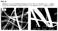
直径が10μm乃至50nmの炭化フェノール樹脂繊維の不織網状組織を含む繊維性材料を作製することができる。この繊維は、BET表面積が比較的大きく、細孔径分布が均一であることが好ましい。 A fibrous material including a non-woven network of carbonized phenol resin fibers having a diameter of 10 μm to 50 nm can be produced. This fiber preferably has a relatively large BET surface area and a uniform pore size distribution.
フェノール樹脂ビーズは、静電噴霧法によって作製することができる。また、フェノール樹脂ビーズは、静電噴霧することによりフィルムを形成することができ、または静電噴霧して個々のビーズとして回収することができる。 The phenol resin beads can be produced by an electrostatic spray method. The phenol resin beads can be formed into a film by electrostatic spraying, or can be recovered as individual beads by electrostatic spraying.
また、静電紡糸した炭化繊維を含むフィルターを含む喫煙製品を提供することができる。例示的な実施態様として、この静電紡糸炭化繊維は活性化した炭化繊維である。 In addition, a smoking product including a filter containing electrospun carbonized fibers can be provided. In an exemplary embodiment, the electrospun carbonized fiber is an activated carbonized fiber.
また、静電紡糸した炭化繊維を含むシガレット・フィルターを提供する。例示的な実施態様として、この静電紡糸炭化繊維は活性化した炭化繊維である。 Also provided is a cigarette filter comprising electrospun carbonized fibers. In an exemplary embodiment, the electrospun carbonized fiber is an activated carbonized fiber.
また、静電紡糸した炭化繊維を含む切断された充填用組成物を提供する。例示的な実施態様として、この静電紡糸炭化繊維は活性化した炭化繊維である。 A cut filling composition comprising electrospun carbonized fibers is also provided. In an exemplary embodiment, the electrospun carbonized fiber is an activated carbonized fiber.
シガレット・フィルターを作製する例示的な方法は、静電紡糸炭化繊維をシガレット・フィルターの空洞および/またはコンポーネント中に組み入れることを含む。 An exemplary method of making a cigarette filter includes incorporating electrospun carbonized fibers into the cavities and / or components of the cigarette filter.
シガレットを作製する例示的な方法は、(i)シガレット製造機に切断された充填用の葉を供給してタバコ・カラムを形成する工程と、(ii)このタバコ・カラムに紙ラッパーを巻いてたばこ棒を形成する工程と、(iii)静電紡糸した炭化繊維を含むシガレット・フィルターをこのたばこ棒に取り付けてシガレットを形成する工程とを含む。 An exemplary method for making a cigarette includes: (i) supplying the cut leaves to a cigarette making machine to form a tobacco column; and (ii) wrapping a paper wrapper around the tobacco column. Forming a cigarette bar; and (iii) attaching a cigarette filter containing electrospun carbonized fibers to the cigarette bar to form a cigarette.
シガレットを作製する別の例示的な方法は、(i)静電紡糸した炭化繊維をたばこ切断された充填用の葉に加える工程と、(ii)得られた切断された充填用の葉をシガレット製造機に供給してタバコ・カラムを形成する工程と、(iii)このタバコ・カラムに紙ラッパーを巻いてシガレットのたばこ棒を形成する工程とを含む。 Another exemplary method of making a cigarette includes: (i) adding the electrospun carbonized fibers to the tobacco cut filling leaves; and (ii) cigarette the resulting cut filling leaves. Supplying a manufacturing machine to form a tobacco column; and (iii) wrapping a paper wrapper around the tobacco column to form a cigarette tobacco rod.
喫煙製品を喫煙する例示的な方法は、静電紡糸した炭化繊維を包含するものであり、この方法がこの製品に火をつけて煙を生じさせ、この製品からその煙を吸い込む工程を含み、この製品の喫煙中に上記静電紡糸炭化繊維が主流煙から1種以上の選ばれた成分を選択的に除去することを特徴とするものである。 An exemplary method of smoking a smoking product includes electrospun carbonized fibers, the method comprising igniting the product to produce smoke and inhaling the smoke from the product; The electrospun carbonized fiber selectively removes one or more selected components from the mainstream smoke during smoking of the product.
例示的な実施態様として、静電紡糸した炭化繊維を含む喫煙製品ラッパーを提供する。例示的実施態様では、この静電紡糸炭化繊維は活性化した炭化繊維である。 As an exemplary embodiment, a smoking product wrapper comprising electrospun carbonized fibers is provided. In an exemplary embodiment, the electrospun carbonized fiber is an activated carbonized fiber.
また、静電噴霧した炭化ビーズを含むフィルターを有する喫煙製品を提供することができる。例示的な実施態様として、この静電噴霧した炭化ビーズは活性化した炭化ビーズである。 Also, a smoking product can be provided having a filter comprising electrostatic sprayed carbonized beads. In an exemplary embodiment, the electrosprayed carbonized beads are activated carbonized beads.
また、静電噴霧した炭化ビーズを含むシガレット・フィルターを提供する。例示的な実施態様として、この静電噴霧炭化ビーズは活性化した炭化ビーズである。 Also provided is a cigarette filter comprising electrostatic sprayed carbonized beads. In an exemplary embodiment, the electrospray carbonized beads are activated carbonized beads.
また、静電噴霧した炭化ビーズを含む切断された充填用組成物を提供する。例示的な実施態様として、この静電噴霧炭化ビーズは活性化した炭化ビーズである。 Also provided is a cut filling composition comprising electrostatic sprayed carbonized beads. In an exemplary embodiment, the electrospray carbonized beads are activated carbonized beads.
シガレット・フィルターを作製する例示的な方法は、静電噴霧した炭化ビーズをシガレット・フィルターの空洞および/またはコンポーネント中に組み入れる工程を含む。 An exemplary method of making a cigarette filter includes incorporating electrostatically sprayed carbonized beads into the cigarette filter cavity and / or component.
例示的な実施態様として、静電噴霧した炭化ビーズを含む喫煙製品を提供する。例示的実施態様では、この静電噴霧炭化ビーズは活性化した炭化ビーズである。 In an exemplary embodiment, a smoking product comprising electrosprayed carbonized beads is provided. In an exemplary embodiment, the electrosprayed carbonized beads are activated carbonized beads.
シガレットを作製する例示的な方法は、(i)シガレット製造機に切断された充填用の葉を供給してタバコ・カラムを形成する工程と、(ii)このタバコ・カラムに紙ラッパーを巻いてたばこ棒を形成する工程と、(iii)静電噴霧した炭化ビーズを含むシガレット・フィルターをこのたばこ棒に取り付けてシガレットを形成する工程とを含む。 An exemplary method for making a cigarette includes: (i) supplying the cut leaves to a cigarette making machine to form a tobacco column; and (ii) wrapping a paper wrapper around the tobacco column. Forming a cigarette bar; and (iii) attaching a cigarette filter containing electrostatic sprayed carbonized beads to the cigarette bar to form a cigarette.
シガレットを作製する別の例示的な方法は、(i)静電噴霧した炭化ビーズをたばこ切断された充填用の葉に加える工程と、(ii)得られた切断された充填用の葉をシガレット製造機に供給してタバコ・カラムを形成する工程と、(iii)このタバコ・カラムに紙ラッパーを巻いてシガレットのたばこ棒を形成する工程とを含む。 Another exemplary method of making a cigarette includes (i) adding electrostatically sprayed carbonized beads to tobacco cut filling leaves, and (ii) cigarette the resulting cut filling leaves. Supplying a manufacturing machine to form a tobacco column; and (iii) wrapping a paper wrapper around the tobacco column to form a cigarette tobacco rod.
喫煙製品を喫煙する例示的な方法は、静電噴霧した炭化ビーズを包含するものであり、この方法がこの製品に火をつけて煙を生じさせ、この製品からその煙を吸い込む工程を含み、この製品の喫煙中に上記静電噴霧炭化ビーズが主流煙から1種以上の選ばれた成分を選択的に除去することを特徴とするものである。 An exemplary method of smoking a smoking product includes electrostatic sprayed carbonized beads, the method comprising igniting the product to produce smoke and inhaling the smoke from the product; The electrostatic spray carbonized beads selectively remove one or more selected components from mainstream smoke during smoking of this product.
繊維、フィルムおよびビーズを含む静電処理されたフェノール樹脂材料を提供する。静電処理によって作製された繊維、繊維性マット、ビーズおよびフィルムは魅力的な材料である。何故なら、これらは、押し出し、乾式紡糸、湿式紡糸、融解紡糸などのような従来の処理技術では達成することができない高い比表面積を有するからである。 An electroprocessed phenolic resin material comprising fibers, films and beads is provided. Fibers, fibrous mats, beads and films made by electrostatic processing are attractive materials. This is because they have a high specific surface area that cannot be achieved with conventional processing techniques such as extrusion, dry spinning, wet spinning, melt spinning and the like.
これらの静電処理されたフェノール樹脂材料の特性を静電処理後の処理によって調整することにより、目的とする用途に適した特性を有する材料を得ることができる。このような静電処理後の処理としては硬化、炭化および活性化が挙げられる。 By adjusting the properties of these electrostatically treated phenol resin materials by the treatment after electrostatic treatment, a material having properties suitable for the intended application can be obtained. Examples of the treatment after the electrostatic treatment include curing, carbonization, and activation.
定義
特記しない限り、本明細書および特許請求の範囲に用いている以下の用語は下記に示した意味を有する:
「ハロ」とは、フルオロ、クロロ、ブロモもしくはヨードを意味する。
Definitions Unless otherwise stated, the following terms used in the specification and claims have the meanings given below:
“Halo” means fluoro, chloro, bromo or iodo.
「ニトロ」とは、−NO2基を意味する。 “Nitro” refers to the —NO 2 radical.
「ヒドロキシ」とは、−OH基を意味する。 “Hydroxy” means the group —OH.
「アルキル」とは、炭素原子数1乃至20、好ましくは1乃至12の直鎖飽和1価炭化水素基、もしくは炭素原子数3乃至20、好ましくは3乃至12の分枝飽和1価炭化水素基を意味する。アルキル基の例としては、メチル、エチル、n−プロピル、イソプロピル、n−ブチル、イソブチル、sec−ブチル、t−ブチル、n−ペンチルなどの基が挙げられるが、これらに限定されるものではない。 “Alkyl” means a linear saturated monovalent hydrocarbon group having 1 to 20 carbon atoms, preferably 1 to 12 carbon atoms, or a branched saturated monovalent hydrocarbon group having 3 to 20 carbon atoms, preferably 3 to 12 carbon atoms. Means. Examples of alkyl groups include, but are not limited to, groups such as methyl, ethyl, n-propyl, isopropyl, n-butyl, isobutyl, sec-butyl, t-butyl, n-pentyl and the like. .
「アルキレン」とは、炭素原子数1乃至20、好ましくは1乃至12の直鎖2価炭化水素基、もしくは炭素原子数3乃至20、好ましくは3乃至12の分枝2価炭化水素基を意味する。アルキレン基の例としては、メチレン、エチレン、2−メチルプロピレンなどが挙げられるが、これらに限定されるものではない。 “Alkylene” means a straight chain divalent hydrocarbon group having 1 to 20 carbon atoms, preferably 1 to 12 carbon atoms, or a branched divalent hydrocarbon group having 3 to 20 carbon atoms, preferably 3 to 12 carbon atoms. To do. Examples of alkylene groups include, but are not limited to, methylene, ethylene, 2-methylpropylene, and the like.
「アルケニル」とは、少なくとも1個の二重結合(−C=C−)を含む、炭素原子数2乃至20、好ましくは2乃至12の直鎖不飽和1価炭化水素基、もしくは炭素原子数3乃至20、好ましくは3乃至12の分枝1価炭化水素基を意味する。アルケニル基の例としては、アリル、ビニル、2−ブテニルなどが挙げられるが、これらに限定されるものではない。 “Alkenyl” refers to a straight-chain unsaturated monovalent hydrocarbon group having 2 to 20, preferably 2 to 12 carbon atoms, containing at least one double bond (—C═C—), or carbon atoms. 3 to 20, preferably 3 to 12, branched monovalent hydrocarbon groups. Examples of alkenyl groups include, but are not limited to, allyl, vinyl, 2-butenyl, and the like.
「アルキニル」とは、少なくとも1個の三重結合(C≡C)を含む、炭素原子数2乃至20、好ましくは2乃至12の直鎖1価炭化水素基、もしくは炭素原子数3乃至20、好ましくは3乃至12の分枝1価炭化水素基を意味する。アルキニル基の例としては、エチニル、プロピニル、2−ブチニルなどが挙げられるが、これらに限定されるものではない。
“Alkynyl” means a straight-chain monovalent hydrocarbon group having 2 to 20, preferably 2 to 12 carbon atoms, or 3 to 20 carbon atoms, preferably containing at least one triple bond (C≡C).
「ハロアルキル」とは、1個以上、好ましくは1乃至6個の同一もしくは異なるハロ原子で置換されているアルキルを意味する。ハロアルキル基の例としては、例えば、トリフルオロメチル、3−フルオロプロピル、2,2−ジクロロエチルなどが挙げられる。 “Haloalkyl” means an alkyl substituted with one or more, preferably 1 to 6 identical or different halo atoms. Examples of haloalkyl groups include trifluoromethyl, 3-fluoropropyl, 2,2-dichloroethyl, and the like.
「ヒドロキシアルキル」とは、2個のヒドロキシ基が存在する場合にこれらが同一炭素原子上にないという条件で、1個以上の−OH基で置換されているアルキルのことを意味する。ヒドロキシアルキル基の例としては、例えば、ヒドロキシメチル、2−ヒドロキシエチル、2−ヒドロキシプロピルなどが挙げられる。 “Hydroxyalkyl” means an alkyl that is substituted with one or more —OH groups provided that when two hydroxy groups are present, they are not on the same carbon atom. Examples of hydroxyalkyl groups include hydroxymethyl, 2-hydroxyethyl, 2-hydroxypropyl, and the like.
「アルキルチオ」とは、「アルキル−S−」基のことを意味し、例えば、メチルチオ、ブチルチオなどが挙げられる。 “Alkylthio” means an “alkyl-S—” group, for example, methylthio, butylthio and the like.
「シアノアルキル」とは、1個以上の−CN基で置換されているアルキルのことを意味する。 “Cyanoalkyl” refers to an alkyl substituted with one or more —CN groups.
「アルコキシ」とは、「アルキル−O−」基のことを意味し、例えば、メトキシ、エトキシ、n−プロポキシ、イソ−プロポキシ、n−ブトキシ、tert−ブトキシ、sec−ブトキシ、n−ペントキシ、n−ヘキソキシ、1,2−ジメチルブトキシなどが挙げられる。 “Alkoxy” means an “alkyl-O—” group, for example, methoxy, ethoxy, n-propoxy, iso-propoxy, n-butoxy, tert-butoxy, sec-butoxy, n-pentoxy, n -Hexoxy, 1,2-dimethylbutoxy and the like.
「アルコキシアルキル」とは、「アルキレン−O−アルキル」基のことを意味し、例えば、2−プロポキシエチレン、3−メトキシブチレンなどが挙げられる。 “Alkoxyalkyl” means an “alkylene-O-alkyl” group and includes, for example, 2-propoxyethylene, 3-methoxybutylene and the like.
「アルケノキシ」とは、「アルケニル−O−」基のことを意味し、例えば、アリルオキシ、ビニルオキシ、2−ブテニルオキシなどが挙げられる。 “Alkenoxy” means an “alkenyl-O—” group and includes, for example, allyloxy, vinyloxy, 2-butenyloxy and the like.
「アルケノキシアルキル」とは、「アルケニル−O−アルキレン」基のことを意味し、例えば、3−アリルオキシ−プロピレン、2−(2−プロペニルオキシ)エチレンなどが挙げられる。 “Alkenoxyalkyl” means an “alkenyl-O-alkylene” group and includes, for example, 3-allyloxy-propylene, 2- (2-propenyloxy) ethylene and the like.
「ハロアルコキシ」とは、「ハロアルキル−S−」基のことを意味し、例えば、トリフルオロメトキシ、2,2−ジクロロエトキシなどが挙げられる。 “Haloalkoxy” means a “haloalkyl-S—” group, and examples include trifluoromethoxy, 2,2-dichloroethoxy, and the like.
「ハロアルキルチオ」とは、「ハロアルキル−S−」基のことを意味し、例えば、トリフルオロメチルチオ、2,2−ジフルオロプロピルチオ、3−クロロプロピルチオなどが挙げられる。 “Haloalkylthio” means a “haloalkyl-S—” group, and examples include trifluoromethylthio, 2,2-difluoropropylthio, 3-chloropropylthio, and the like.
「アミノ」とは、「−NRaRb」基のことを意味し、この場合、RaおよびRbは、独立にH、アルキル、ハロアルキル、アルケニル、シクロアルキル、アリール、置換アリール、ヘテロアリールもしくは置換ヘテロアリールである。 “Amino” means a “—NR a R b ” group, where R a and R b are independently H, alkyl, haloalkyl, alkenyl, cycloalkyl, aryl, substituted aryl, heteroaryl. Or substituted heteroaryl.
「カルボキシ」とは、「C(O)」基を意味する。 “Carboxy” means a “C (O)” group.
「アシルオキシ」とは、−C(O)R’基のことを意味し、この場合、R’はアルキル、アルケニル、アルキニル、アリール、置換アリール、ヘテロアリールもしくは置換ヘテロアリールである。 “Acyloxy” refers to the group —C (O) R ′, where R ′ is alkyl, alkenyl, alkynyl, aryl, substituted aryl, heteroaryl or substituted heteroaryl.
「シクロアルキル」とは、環原子数3乃至8の環式飽和炭化水素基を意味し、この場合、1個もしくは2個のC原子が任意にカルボニル基で置換される。このシクロアルキル基は、任意に、1個、2個もしくは3個の置換基、好ましくはアルキル、アルケニル、ハロ、ヒドロキシル、シアノ、ニトロ、アルコキシ、ハロアルキル、アルケニル、アルケノキシで置換される。代表的な例としては、シクロプロピル、シクロヘキシル、シクロペンチルなどが挙げられるが、これらに限定されるものではない。 “Cycloalkyl” means a cyclic saturated hydrocarbon group having 3 to 8 ring atoms, in which one or two C atoms are optionally substituted with a carbonyl group. The cycloalkyl group is optionally substituted with 1, 2 or 3 substituents, preferably alkyl, alkenyl, halo, hydroxyl, cyano, nitro, alkoxy, haloalkyl, alkenyl, alkenoxy. Representative examples include, but are not limited to, cyclopropyl, cyclohexyl, cyclopentyl and the like.
「アリール」とは、環原子数6乃至14の1価単環式もしくは二環式芳香族炭素環基を意味する。例としては、フェニル、ナフチルおよびアンスリルが挙げられるが、これらに限定されるものではない。このアリール環は、酸素、窒素もしくは硫黄から独立に選ばれる1個もしくは2個のヘテロ原子を任意に含む5、6もしくは7員環の単環式非芳香族環であって残りの環原子がCでありこのC原子の1個もしくは2個がカルボニルで任意に置換されている非芳香族環に、任意に縮合することができる。縮合環を有する代表的なアリール基としては、2,5−ジヒドロベンゾ[b]オキセピン、2,3−ジヒドロベンゾ[1,4]ジオキソール、クロマン、イソクロマン、2,3−ジヒドロベンゾフラン、1,3−ジヒドロイソベンゾフラン、ベンゾ[1,3]ジオキソール、1,2,3,4−テトラヒドロイソキノリン、1,2,3,4−テトラヒドロキノリン、2,3−ジヒドロ−1H−インドール、2,3−ジヒドロ1H−イソインドール、ベンズイミダゾール−2−オン、2−H−ベンズオキサゾール−2−オンなどが挙げられるが、これらに限定されるものではない。 “Aryl” means a monovalent monocyclic or bicyclic aromatic carbocyclic group having 6 to 14 ring atoms. Examples include but are not limited to phenyl, naphthyl and anthryl. This aryl ring is a 5-, 6- or 7-membered monocyclic non-aromatic ring optionally containing 1 or 2 heteroatoms independently selected from oxygen, nitrogen or sulfur, and the remaining ring atoms are It can optionally be fused to a non-aromatic ring that is C and in which one or two of the C atoms are optionally substituted with carbonyl. Representative aryl groups having a condensed ring include 2,5-dihydrobenzo [b] oxepin, 2,3-dihydrobenzo [1,4] dioxole, chroman, isochroman, 2,3-dihydrobenzofuran, 1,3 -Dihydroisobenzofuran, benzo [1,3] dioxole, 1,2,3,4-tetrahydroisoquinoline, 1,2,3,4-tetrahydroquinoline, 2,3-dihydro-1H-indole, 2,3-dihydro Examples include 1H-isoindole, benzimidazol-2-one, 2-H-benzoxazol-2-one, but are not limited thereto.
「置換アリール」とは、1個以上の置換基、好ましくはアルキル、アルケニル、アルキニル、ハロ、アルコキシ、アシルオキシ、アミノ、ヒドロキシル、カルボキシ、シアノ、ニトロおよびチオアルキルからなる群から選ばれる1乃至3個の置換基によって置換されているアリール環を意味する。このアリール環は、酸素、窒素もしくは硫黄から独立に選ばれる1個もしくは2個のヘテロ原子を任意に含む5、6もしくは7員環の単環式非芳香族環であって残りの環原子がCでありこのC原子の1個もしくは2個がカルボニルで任意に置換されている非芳香族環に、任意に縮合することができる。 “Substituted aryl” refers to one or more substituents, preferably 1 to 3 selected from the group consisting of alkyl, alkenyl, alkynyl, halo, alkoxy, acyloxy, amino, hydroxyl, carboxy, cyano, nitro and thioalkyl. It means an aryl ring substituted by a substituent. This aryl ring is a 5-, 6- or 7-membered monocyclic non-aromatic ring optionally containing 1 or 2 heteroatoms independently selected from oxygen, nitrogen or sulfur, and the remaining ring atoms are It can optionally be fused to a non-aromatic ring that is C and in which one or two of the C atoms are optionally substituted with carbonyl.
「ヘテロアリール」とは、N、OもしくはSから選ばれる1個、2個もしくは3個の環ヘテロ原子を含む環原子数5乃至10の1価単環式もしくは二環式芳香族基であって残りの環原子がCである芳香族基を意味する。代表的な例としては、チエニル、ベンゾチエニル、ピリジル、ピラジニル、ピリミジニル、ピリダジニル、キノリニル、キノキサリニル、イミダゾリル、フラニル、ベンゾフラニル、チアゾリル、イソキサゾリル、ベンズイソキサゾリル、ベンズイミダゾリル、トリアゾリル、ピラゾリル、ピロリル、インドリル、2−ピリドニル、4−ピリドニル、N−アルキル−2−ピリドニル、ピラジノニル、ピリダジノニル、ピリミジノニル、オキサゾロニルなどが挙げられるが、これらに限定されるものではない。 “Heteroaryl” is a monovalent monocyclic or bicyclic aromatic group having 5 to 10 ring atoms containing 1, 2 or 3 ring heteroatoms selected from N, O or S. An aromatic group in which the remaining ring atoms are C. Representative examples include thienyl, benzothienyl, pyridyl, pyrazinyl, pyrimidinyl, pyridazinyl, quinolinyl, quinoxalinyl, imidazolyl, furanyl, benzofuranyl, thiazolyl, isoxazolyl, benzisoxazolyl, benzimidazolyl, triazolyl, pyrazolyl, pyrrolyl, indolyl , 2-pyridonyl, 4-pyridonyl, N-alkyl-2-pyridonyl, pyrazinonyl, pyridazinonyl, pyrimidinonyl, oxazolonyl, and the like, but are not limited thereto.
「置換ヘテロアリール」とは、1個以上の置換基、好ましくはアルキル、アルケニル、アルキニル、ハロ、アルコキシ、アシルオキシ、アミノ、ヒドロキシル、カルボキシ、シアノ、ニトロおよびチオアルキルからなる群から選ばれる1乃至3個の置換基によって置換されているヘテロアリール環を意味する。 “Substituted heteroaryl” is one or more substituents, preferably 1 to 3 selected from the group consisting of alkyl, alkenyl, alkynyl, halo, alkoxy, acyloxy, amino, hydroxyl, carboxy, cyano, nitro and thioalkyl Means a heteroaryl ring substituted by a substituent of
「アリールオキシ」とは、「−O−Ar」基を意味し、この場合、Arはアリール基もしくは置換アリール基である。例としては、ベンジルオキシ、4−トリフルオロメチル−ベンジルオキシなどが挙げられるが、これらに限定されるものではない。 “Aryloxy” refers to the group “—O—Ar”, where Ar is an aryl or substituted aryl group. Examples include, but are not limited to, benzyloxy, 4-trifluoromethyl-benzyloxy, and the like.
「アリールアルコキシ」とは、「−O−アルキレン−Ar」基を意味し、この場合、Arはアリール基もしくは置換アリール基である。例としては、2−(フェニル)エトキシ、3−(フェニル)プロポキシなどが挙げられるが、これらに限定されるものではない。 “Arylalkoxy” refers to an “—O-alkylene-Ar” group, where Ar is an aryl or substituted aryl group. Examples include, but are not limited to, 2- (phenyl) ethoxy, 3- (phenyl) propoxy and the like.
「アリールアルコキシアルキル」とは、「−アルキレン−O−アルキレン−Ar」基を意味し、この場合、ARはアリール基もしくは置換アリール基である。例としては、ベンジルオキシ−プロピレン、ベンジルオキシ−エチレンなどが挙げられるが、これらに限定されるものではない。 “Arylalkoxyalkyl” means an “-alkylene-O-alkylene-Ar” group, where AR is an aryl or substituted aryl group. Examples include, but are not limited to, benzyloxy-propylene, benzyloxy-ethylene, and the like.
「アリールカルボキシアルキル」とは、「−R’(O)R」基を意味し、この場合、R’は上記のアルキレン基であり、Rは上記のアルキル基である。 “Arylcarboxyalkyl” means a “—R ′ (O) R” group, where R ′ is an alkylene group as defined above and R is an alkyl group as defined above.
「カルボキシリック」とは、−C(O)−OH基を意味する。 “Carboxylic” means a —C (O) —OH group.
「アルキルオキシカルボキシ」とは、−C(O)−OR基を意味し、この場合、Rは上記のアルキル基である。 “Alkyloxycarboxy” means a —C (O) —OR group, where R is an alkyl group as defined above.
「スルホン酸」とは、−SO3H基を意味する。 “Sulfonic acid” refers to the group —SO 3 H.
「静電処理もしくは静電的処理」とは、重合体系に電場をかけることにより重合体系から材料を形成する技術のことを意味する。静電処理は、本明細書に記載した静電紡糸および静電噴霧の技術を含む。これらの静電処理技術を用いることによりナノ繊維、マイクロ繊維、ビーズ、薄フィルム、もしくはこれらの組み合わせを作製することができる。 “Electrostatic treatment or electrostatic treatment” means a technique for forming a material from a polymer system by applying an electric field to the polymer system. Electrostatic treatment includes the electrospinning and electrostatic spraying techniques described herein. By using these electrostatic treatment techniques, nanofibers, microfibers, beads, thin films, or combinations thereof can be produced.
「静電処理された材料」とは、重合体系を静電処理することにより作製された材料のことを意味する。静電処理された材料としては、ナノ繊維、マイクロ繊維、合体してビーズとなる粒子、非相溶性溶媒から析出したビーズもしくは繊維、薄フィルム、乾式多孔フィルム、繊維性マットもしくはウェブなど、およびこれらの組み合わせが挙げられる。 “Electrostatically treated material” means a material made by electrostatically treating a polymer system. Electrostatically treated materials include nanofibers, microfibers, particles that coalesce into beads, beads or fibers precipitated from incompatible solvents, thin films, dry porous films, fibrous mats or webs, and the like The combination of is mentioned.
本明細書に記載した静電処理材料は、前駆体重合体系を静電紡糸および/または静電噴霧することにより作製される。この前駆体重合体系はフェノール重合体系であることが好ましい。従って、本明細書に記載した静電処理材料は、フェノール重合体系を静電的に処理することにより作製される。このフェノール重合体系は、フェノール重合体溶液もしくはフェノール重合体溶融液とすることができる。 The electroprocessed materials described herein are made by electrospinning and / or electrospraying a precursor polymer system. This precursor polymer system is preferably a phenol polymer system. Accordingly, the electrostatic processing material described herein is made by electrostatically processing a phenolic polymer system. This phenol polymer system can be a phenol polymer solution or a phenol polymer melt.
フェノール重合体系
この溶液もしくは溶融液のフェノール重合体は、当業者に公知の技術により合成された市販のフェノール樹脂およびフェノール重合体、フェノール共重合体、フェノール重合体と他の重合体とのブレンド、添加物を含むフェノール重合体、フェノール共重合体およびブレンド、ならびにこれらの混合物を含む任意のフェノール重合体とすることができる。
Phenol polymer system The phenol polymer of this solution or melt is a commercially available phenol resin and phenol polymer synthesized by techniques known to those skilled in the art, a phenol copolymer, a blend of a phenol polymer and other polymers, It can be any phenolic polymer including phenolic polymers including additives, phenolic copolymers and blends, and mixtures thereof.
このフェノール重合体中のフェニル環は、1個以上、好ましくは1個もしくは2個のヒドロキシ基で置換されている。また、これらのフェノール重合体中のフェニル環は、1個以上の官能基、例えば、ハロ、ニトロ、アルキル、アルケニル、アルキニル、ハロアルキル、ヒドロキシアルキル、シアノアルキル、アルキルチオ、アルコキシ、アルコキシアルキル、アルケノキシ、アルケノキシアルキル、ハロアルコキシ、ハロアルキルチオ、アミノ、カルボキシリック、アシルオキシ、シクロアルキル、アリール、置換アリール、ヘテロアリール、置換ヘテロアリール、アリールオキシ、アリールアルコキシ、アリールアルコキシアルキル、アルキルカルボキシルアルキル、アルキルオキシカルボキシ、スルホン酸、およびこれらの組み合わせで置換することもできる。 The phenyl ring in this phenol polymer is substituted with one or more, preferably one or two hydroxy groups. In addition, the phenyl ring in these phenolic polymers has one or more functional groups such as halo, nitro, alkyl, alkenyl, alkynyl, haloalkyl, hydroxyalkyl, cyanoalkyl, alkylthio, alkoxy, alkoxyalkyl, alkenoxy, alkenyl. Noxyalkyl, haloalkoxy, haloalkylthio, amino, carboxylic, acyloxy, cycloalkyl, aryl, substituted aryl, heteroaryl, substituted heteroaryl, aryloxy, arylalkoxy, arylalkoxyalkyl, alkylcarboxylalkyl, alkyloxycarboxy, Substitutions can also be made with sulfonic acids and combinations thereof.
上記のヒドロキシ基もしくは他の官能基は、反応させることによりこのフェノール重合体中に別の種類の官能基を提供することができる。例えば、このフェノール重合体のヒドロキシ基をアミノプロピルシランと反応させることにより、フェノール重合体にアミノ官能基をグラフトすることができる。これらの官能基は、上記フェノール重合体を静電的に処理した後、保持されることになる。 The above hydroxy groups or other functional groups can be reacted to provide another type of functional group in the phenolic polymer. For example, an amino functional group can be grafted to the phenol polymer by reacting the hydroxy group of the phenol polymer with aminopropylsilane. These functional groups will be retained after electrostatic treatment of the phenolic polymer.
フェノール重合体の分子量は、このフェノール重合体を静電的に処理することができる限りにおいて、所望通りに変化させることができる。つまり、このフェノール重合体の所望の分子量は、フェノール溶液もしくはフェノール重合体溶融液を静電的に処理することができるかどうかによって変化させることができる。さらに、フェノール溶液を静電的に処理することができれば、上記分子量は、この溶液の濃度の変化に伴って変化させることができる。さらに、上記フェノール重合体の分子量は、この重合体系を静電処理するのに用いられる技術(即ち、重合体系を静電紡糸するのか静電噴霧するのか)に応じて変化させることができる。さらに、このフェノール重合体の分子量は、どのフェノール重合体を用いるかによって変化させることができる。一般的には、可能な限り直鎖状であり、この所望の直鎖性を維持しながらできる限り高い分子量を有するフェノール重合体を用いることが望ましい。 The molecular weight of the phenolic polymer can be varied as desired as long as the phenolic polymer can be treated electrostatically. That is, the desired molecular weight of the phenol polymer can be varied depending on whether the phenol solution or the phenol polymer melt can be treated electrostatically. Furthermore, if the phenol solution can be treated electrostatically, the molecular weight can be changed as the concentration of the solution changes. Furthermore, the molecular weight of the phenolic polymer can be varied depending on the technique used to electrostatically treat the polymer system (ie, whether the polymer system is electrospun or electrostatically sprayed). Furthermore, the molecular weight of the phenol polymer can be changed depending on which phenol polymer is used. In general, it is desirable to use a phenol polymer that is as linear as possible and has the highest molecular weight possible while maintaining this desired linearity.
一般的には、静電処理に際して、上記フェノール重合体の分子量は、約900乃至50,000とすることができる。例えば、このフェノール重合体が静電紡糸される場合、その分子量は約9,000乃至30,000であることが好ましい。この比較的高い分子量の直鎖フェノール重合体、特にノボラックは、比較的低分子量の分枝フェノール重合体と同様な溶媒中の重量パーセント条件で紡糸させることができる。同様な濃度を有する比較的高分子量の溶液を用いると、得られるナノ繊維の強度を増大させることができる。 In general, the molecular weight of the phenol polymer can be about 900 to 50,000 during electrostatic treatment. For example, when the phenol polymer is electrospun, the molecular weight is preferably about 9,000 to 30,000. This relatively high molecular weight linear phenolic polymer, particularly novolak, can be spun in weight percent conditions in the same solvent as the relatively low molecular weight branched phenolic polymer. Using relatively high molecular weight solutions with similar concentrations can increase the strength of the resulting nanofibers.
市販のフェノール重合体はフェノール樹脂として入手可能である。フェノール樹脂は、フェノールとホルムアルデヒドとの縮合生成物であり、リアクタント・レシオおよび使用触媒によって、主に2つのタイプ、ノボラックとレゾールとに区別することができる。ノボラックは、酸触媒を用いて1未満のホルムアルデヒド/フェノール(「F/P」)比で作製されるので、直鎖構造を有し、架橋剤により硬化する。レゾールは、アルカリ触媒を用いて1以上のフェノール/ホルムアルデヒド(「F/P」)比で作製されるので、硬化剤を必要とせずに単独で硬化することができる多官能性(multifunctionality)構造を有する。上記フェノール重合体は、市販ノボラック、市販レゾール、およびこれらの混合物とすることができる。ノボラック・フェノール樹脂は種々の分子量のものが市販されており、それらは全て本発明に適したものとすることができ、これらはデュレズ社(アディソン、TX)から市販されている。また、レゾール・フェノール樹脂も種々の分子量のものが市販されており、それらは全て本発明に適したものとすることができ、これらもデュレズ社(アディソン、TX)から市販されている。 Commercially available phenolic polymers are available as phenolic resins. Phenol resin is a condensation product of phenol and formaldehyde, and can be distinguished mainly into two types, novolak and resole, depending on the reactant ratio and the catalyst used. Novolac is made with an acid catalyst at a formaldehyde / phenol (“F / P”) ratio of less than 1, so it has a linear structure and is cured by a crosslinker. Resols are made with an alkali catalyst at a ratio of one or more phenol / formaldehyde (“F / P”), so that they have a multi-functional structure that can be cured alone without the need for a curing agent. Have. The phenolic polymer can be a commercially available novolak, a commercially available resole, and a mixture thereof. Novolac phenolic resins are available in various molecular weights, all of which can be suitable for the present invention, and are commercially available from Durez (Addison, TX). Resole-phenolic resins having various molecular weights are also commercially available, and they can all be suitable for the present invention, and these are also commercially available from Durez (Addison, TX).
また、ノボラック・フェノール樹脂から誘導された炭素材は、マスト・カーボン社(英国)からNovocarb(商標)として、またアメリカン・カイノール社(プレザントビル、NY)からNovoloid(商標)として入手可能である。また、フェノール樹脂は、ジョージア・パシフィック社(アトランタ、GA)からBakelite AG(商標)として入手可能である。さらに、フェノール樹脂は、種々のメーカー、例えばアモコ・エレクトロニック・マテリアルズ社(アルファレッタ、GA)、サイテック・ファイバーライト社(テンペ、AZ)、オクシデンタル・ケミカル社(ダラス、TX)、プラスロック社(バッファロー、NY)、プラスチックス・エンジニアリング社(オーバーンヒルズ、MI)、レジノイド・エンジニアリング社(ヘブロン、OH)、ロジャース社(ロジャーズ、CT)、アメテック/ウエストチェスター・プラスチックス社(ネスケホーニング、PA)、スケネクタディ・インターナショナル社(スケネクタディ、NY)、ソルティア社(セントルイス、MO)およびユニオン・カーバイド社(ダンベリー、CT)からも市販されている。 Carbon materials derived from novolac phenolic resins are also available as Novocarb (TM) from Mast Carbon (UK) and Novoloid (TM) from American Kynol (Pleasantville, NY). The phenolic resin is also available as Bakelite AG ™ from Georgia Pacific (Atlanta, GA). Furthermore, phenolic resins are available from various manufacturers such as Amoco Electronic Materials (Alpharetta, GA), Cytec Fiberlight (Tempe, AZ), Occidental Chemical (Dallas, TX), Plus Rock ( Buffalo, NY), Plastics Engineering (Auburn Hills, MI), Resinoid Engineering (Hebron, OH), Rogers (Rogers, CT), Ametech / Westchester Plastics (Neske Honing, PA) Also available from Schenectady International (Schenectady, NY), Saltia (St. Louis, MO) and Union Carbide (Danbury, CT).
市販のフェノール樹脂は比較的安価な重合体であるので、ナノ繊維、マイクロ繊維、フィルムなど、およびこれらの組み合わせを含む比較的安価な静電処理材料およびこれらの静電処理材料を用いた最終使用製品が得られる。これらのフェノール樹脂は、比較的安価であることから、静電処理材料およびこの静電処理材料を含む製品の大量生産に際し、有利である。フェノール樹脂から得られる静電処理材料のその他の利点としては、化学収率や化学的純度が高く、生体適合性が良好で、毒性特性が低く、耐熱性や耐腐食性に優れ、吸着剤として使用するための活性化が容易であることが挙げられる。 Since commercially available phenolic resins are relatively inexpensive polymers, relatively inexpensive electrostatic processing materials including nanofibers, microfibers, films, etc., and combinations thereof, and end use using these electrostatic processing materials A product is obtained. Since these phenolic resins are relatively inexpensive, they are advantageous for mass production of electrostatic processing materials and products containing the electrostatic processing materials. Other advantages of electrostatic processing materials obtained from phenolic resins include high chemical yield and chemical purity, good biocompatibility, low toxicity characteristics, excellent heat resistance and corrosion resistance, and as an adsorbent. It is mentioned that activation for use is easy.
これらのフェノール重合体は、市販のフェノール重合体の他に、フェノール重合体を合成するための任意の方法によって合成することができる。こうした方法としては、例えば、任意の反応性フェノールもしくは置換フェノールと反応性アルデヒドとの縮合が挙げられる。さらに、フェノール重合体を合成する方法としては、アッカラほか、「ジオキサン中におけるホースラディシュ・ペルオキシダーゼによる重合体の合成および生成重合体の特徴付け」Journal of Polymer Science:Part A:Polymer Chemistry、29(1991年)p1561−1574に記載されている、酵素を用いたフェノールもしくは置換フェノールの重合が挙げられる。これらのフェノール重合体を合成するために用いることができるフェノールとしては、例えば、フェノール[C6H5OH]、クレゾール(メタ−、オルソ−、パラ−およびこれらの混合物を含む)[CH3C6H4OH]、キシレノール[(CH3)2C6H3OH]、p−フェニルフェノール[C6H5C6H4OH]、ビスフェノール[(C6H4OH)2]、レゾルシノール[C6H4(OH)2]、p−第3ブチルフェノール、アルキル置換フェノール、ジフェニロールプロパンなど、およびこれらの混合物が挙げられる。上記フェノール重合体を合成するために用いることができる反応性アルデヒドとしては、例えば、ホルムアルデヒドおよびフルフラールが挙げられる。 These phenol polymers can be synthesized by an arbitrary method for synthesizing a phenol polymer in addition to a commercially available phenol polymer. Such methods include, for example, condensation of any reactive phenol or substituted phenol with a reactive aldehyde. Furthermore, as a method of synthesizing a phenol polymer, Akara et al., “Synthesis of polymers by horseradish peroxidase in dioxane and characterization of the produced polymer” Journal of Polymer Science: Part A: Polymer Chemistry, 29 (1991). (Year) Polymerization of phenol or substituted phenol using enzymes described in p1561-1574. Phenols that can be used to synthesize these phenol polymers include, for example, phenol [C 6 H 5 OH], cresols (including meta-, ortho-, para- and mixtures thereof) [CH 3 C 6 H 4 OH], xylenol [(CH 3 ) 2 C 6 H 3 OH], p-phenylphenol [C 6 H 5 C 6 H 4 OH], bisphenol [(C 6 H 4 OH) 2 ], resorcinol [ C 6 H 4 (OH) 2 ], p-tertiary butylphenol, alkyl-substituted phenol, diphenylolpropane, and the like, and mixtures thereof. Examples of reactive aldehydes that can be used to synthesize the phenolic polymer include formaldehyde and furfural.
レゾールおよびノボラックは、ホルムアルデヒドとフェノールとの反応から合成することができる。レゾールもしくはノボラックのいずれが形成されるかは、触媒の形態(mode)およびフェノールに対するホルムアルデヒドのモル比によって決まる。例えば、Gardziella・A、Pilato・L.A.、Knop・A「Phenolic Resins:Chermistry,Applications,Standardization,Safety and Ecology」第2版、Springer−Verlag:ベルリン、2000年を参照されたい。レゾールおよびノボラック樹脂を架橋するには、通常種々の硬化条件が用いられる。レゾールの硬化は、熱処理、酸もしくは塩基、または場合によっては、硬化プロセスを促進すると報告されている他の特別な硬化系、例えば、カルボン酸エステル、無水物、アミドおよび炭酸塩によって行うことができる。例えば、Peng・W、Riedl・B、Barry・A.O.J.Appl.Polym.Sci.1993年、48:p1757を参照されたい。ノボラックを硬化するには、ホルムアルデヒドの供給源もしくは広く用いられている硬化剤ヘキサメチレンテトラミンが必要とされるが、さらに、固形レゾール、ビスメチロール・クレゾール、ビスオキサゾリンおよびビスベンズオキサジンを用いる他の方法も報告されている。例えば、Sergeev・V.A.ほか、Poly Sci.Ser B、1995年、37(5/6):p273、Cuthbertson・B.M.、Tilsa・O.、Devinney・M.L.、Tufts・TA、SAMPE、1989年、34:p2483、およびPilato・L.A.、ミクノMichno・M.J.、Advanced Composite Materials、Springer−Verlag:ベルリン、1994年を参照されたい。 Resoles and novolacs can be synthesized from the reaction of formaldehyde and phenol. Whether a resole or novolac is formed depends on the catalyst mode and the molar ratio of formaldehyde to phenol. For example, Gardziella A, Pilato L. A. Knop A, "Phenolic Resins: Chemistry, Applications, Standardization, Safety and Ecology", 2nd edition, Springer-Verlag: Berlin, 2000. Various crosslinking conditions are usually used to crosslink resole and novolac resins. Curing of the resole can be done by heat treatment, acid or base, or possibly other special curing systems that are reported to accelerate the curing process, such as carboxylic esters, anhydrides, amides and carbonates. . For example, Peng · W, Riedl · B, Barry · A. O. J. et al. Appl. Polym. Sci. 1993, 48: p1757. Curing novolak requires a source of formaldehyde or the widely used curing agent hexamethylenetetramine, but also other methods using solid resole, bismethylol cresol, bisoxazoline and bisbenzoxazine Has also been reported. For example, Sergeev · V. A. Et al., Poly Sci. Ser B, 1995, 37 (5/6): p273, Cuthbertson B.C. M.M. Tilsa O. Devinney, M .; L. Tufts, TA, SAMPE, 1989, 34: p2483, and Pilato, L .; A. Mikuno Michno M. J. et al. , Advanced Composite Materials, Springer-Verlag: Berlin, 1994.
また、上記フェノール重合体は、フェノール重合体と共重合性単量体との共重合体とすることもできる。この共重合性単量体としては、例えば、クレゾール(メタ−、オルソ−、パラ−およびこれらの混合物を含む)、キシレノール、p−フェニルフェノール、ビスフェノール、レゾルシノール、p−第3ブチルフェノール、アルキル置換フェノール、ジフェニロールプロパン、およびp−ビニルフェノールもしくは2−(4−ヒドロキシフェニル)エチルメタクリレートのようなメタクリレートなどの別の重合性官能基を有するフェノールなど、ならびにこれらの混合物が挙げられる。また、この共重合性単量体としては、ポリエステル、不飽和ポリエステル、エポキシ、メラミン−ホルムアルデヒド、ポリイミド、尿素−ホルムアルデヒドなど、およびこれらの混合物も挙げられる。さらに、上記共重合性単量体としては、スチレン、フタル酸ジアリル、ジアセトンアクリルアミド、ビニルトルエンなど、およびこれらの混合物が挙げられる。 Moreover, the said phenol polymer can also be made into the copolymer of a phenol polymer and a copolymerizable monomer. Examples of the copolymerizable monomer include cresol (including meta-, ortho-, para- and mixtures thereof), xylenol, p-phenylphenol, bisphenol, resorcinol, p-tert-butylphenol, and alkyl-substituted phenol. , Diphenylolpropane, and phenols with other polymerizable functional groups such as methacrylates such as p-vinylphenol or 2- (4-hydroxyphenyl) ethyl methacrylate, and mixtures thereof. The copolymerizable monomer also includes polyester, unsaturated polyester, epoxy, melamine-formaldehyde, polyimide, urea-formaldehyde, and mixtures thereof. Furthermore, examples of the copolymerizable monomer include styrene, diallyl phthalate, diacetone acrylamide, vinyl toluene, and the like, and mixtures thereof.
例えば、フェノール重合体(類)および共重合性単量体(類)は、フェノール共重合体を作製するための重合開始剤の存在下に有機溶媒重合メジウム中で共重合させることができる。フェノール重合体(類)および共重合すべき単量体(類)の添加ならびに重合の開始の順序は、フェノール共重合体が形成される限り、変更することができる。例えば、共重合すべき単量体類を全て反応器に加えた後、重合を開始させてもよい。あるいは、フェノール重合体(類)の一部と単量体類とを反応器に加えて重合を開始させてもよい。適切な時間内に、残りのフェノール重合体(類)および/または単量体類を加えることができ、この場合、この残余のフェノール重合体類および単量体類は、フェノール共重合体が形成される限り、全てを一度に、もしくは段階的に加えることができる。フェノール重合体(類)および共重合すべき単量体類を、最初に全て反応器に加えた後、重合を開始することが好ましい。共重合させた後の反応混合物は、冷却し、必要に応じて乾燥することにより、もろい樹脂を得ることができる。このもろい樹脂を粉砕することによって粉末状フェノール共重合体を得ることができる。 For example, the phenolic polymer (s) and the copolymerizable monomer (s) can be copolymerized in an organic solvent polymerization medium in the presence of a polymerization initiator for making the phenolic copolymer. The order of addition of the phenolic polymer (s) and monomer (s) to be copolymerized and the initiation of the polymerization can be varied as long as the phenolic copolymer is formed. For example, the polymerization may be initiated after all the monomers to be copolymerized have been added to the reactor. Alternatively, a portion of the phenolic polymer (s) and monomers may be added to the reactor to initiate the polymerization. Within the appropriate time, the remaining phenolic polymer (s) and / or monomers can be added, in which case the remaining phenolic polymers and monomers are formed by the phenolic copolymer. All can be added at once or in steps as long as possible. Preferably, the phenolic polymer (s) and the monomers to be copolymerized are all initially added to the reactor and then the polymerization is started. A fragile resin can be obtained by cooling the reaction mixture after copolymerization and drying it as necessary. A powdery phenol copolymer can be obtained by pulverizing this brittle resin.
また、上記フェノール重合体は、フェノール重合体と、このフェノール重合体の溶液もしくは溶融液と混和性の任意の他の重合体系とのブレンドとすることもできる。フェノール重合体は、水素結合アクセプターである任意の重合体系と混和性であってもよい。フェノール重合体とブレンドすることができる重合体としては、例えば、ポリアクリル酸、ポリ酢酸ビニル、酢酸セルロース、ポリエチレンイミン、ポリ(エチレン−コ−ビニルアセテート)、ポリ乳酸、およびこれらの混合物などが挙げられる。このフェノール重合体を別の重合体系とブレンドすることにより、最終的なフェノール樹脂静電処理材料の特定の特性を得、向上させ、もしくは変化させることができる。従って、混和性の重合体系は、得るべき、もしくは向上させるべき、または変化させるべき特性に基づいて選択することができる。例えば、フェノール樹脂繊維の力学的特性を改善するには、上記フェノール重合体をポリアクリル酸とブレンドすることができる。選択されるこの混和性重合体系は、このフェノール重合体の溶液もしくは溶融液中にブレンドした後に、静電処理する。 The phenol polymer can also be a blend of the phenol polymer and any other polymer system that is miscible with the solution or melt of the phenol polymer. The phenolic polymer may be miscible with any polymer system that is a hydrogen bond acceptor. Polymers that can be blended with the phenolic polymer include, for example, polyacrylic acid, polyvinyl acetate, cellulose acetate, polyethyleneimine, poly (ethylene-co-vinyl acetate), polylactic acid, and mixtures thereof. It is done. By blending this phenolic polymer with another polymer system, certain properties of the final phenolic resin electrostatic treatment material can be obtained, enhanced, or altered. Thus, a miscible polymer system can be selected based on the properties to be obtained, improved, or changed. For example, to improve the mechanical properties of phenolic resin fibers, the phenolic polymer can be blended with polyacrylic acid. The selected miscible polymer system is electrostatically treated after blending into a solution or melt of the phenolic polymer.
また、上記フェノール重合体に添加剤をブレンドもしくはドープすることにより、このフェノール重合体の溶液の静電処理の特定の特性を得、向上させ、もしくは変化させることができる。さらに、添加剤を加えることにより、フェノール樹脂静電処理材料の特定の特性を得、向上させ、もしくは変化させることができ、またはこのフェノール樹脂材料のその後の処理に役立たせることができる。このフェノール重合体に用いるのに適した添加剤の例としては、例えば、種々の大きさおよび形状の分散金属、金属酸化物、金属塩、界面活性剤、硬化/架橋剤、安定剤、多孔性向上剤(porosity enhancer)、非揮発性および非相溶性溶媒、各種塩、ならびにこれらの混合物が挙げられる。これらの添加剤は炭化時に作用して炭化を安定化もしくは促進することができる。添加剤の具体的な例としては、銅ナノ粒子、酸化鉄ナノ粒子、ヘキサメチレンテトラミン、PtCl2などが挙げられる。 Also, by blending or doping an additive to the phenolic polymer, specific characteristics of electrostatic treatment of the phenolic polymer solution can be obtained, improved, or changed. Furthermore, by adding additives, certain properties of the phenolic resin electrostatic treatment material can be obtained, improved, or altered, or can be useful for subsequent processing of the phenolic resin material. Examples of additives suitable for use in this phenolic polymer include, for example, dispersed metals, metal oxides, metal salts, surfactants, curing / crosslinking agents, stabilizers, porosity of various sizes and shapes Examples include enhancers, non-volatile and incompatible solvents, various salts, and mixtures thereof. These additives can act during carbonization to stabilize or promote carbonization. Specific examples of the additive include copper nanoparticles, iron oxide nanoparticles, hexamethylenetetramine, PtCl 2 and the like.
さらに、得られた静電処理材料に対し、処理後に添加剤を注入することができる。従って、硬化フェノール樹脂材料を金属塩溶液に浸漬するか、このフェノール樹脂材料に金属を含浸させることにより、硬化フェノール樹脂材料に金属塩もしくは金属粒子を含浸させることができる。さらに、この硬化フェノール樹脂材料を塩基中に浸漬することにより、フェノキシド材料を作製することができる。このフェノキシド材料を金属塩溶液中に浸漬することにより、フェノキシド塩を作製することができる。さらに、この硬化フェノール樹脂材料はスルホン化することができる。 Furthermore, an additive can be injected into the obtained electrostatic processing material after the processing. Therefore, the cured phenol resin material can be impregnated with metal salt or metal particles by immersing the cured phenol resin material in a metal salt solution or impregnating the phenol resin material with metal. Furthermore, a phenoxide material can be produced by immersing this cured phenol resin material in a base. A phenoxide salt can be produced by immersing this phenoxide material in a metal salt solution. Furthermore, the cured phenolic resin material can be sulfonated.
上記フェノール重合体は、溶液、分散液もしくは溶融液として静電処理に供することができる。フェノール重合体溶液はフェノール重合体の適切な溶媒の溶液である。また、適切な溶媒中にフェノール重合体を分散させたフェノール重合体分散液をこの処理に用いることもできる。上記溶液の溶媒は、上記フェノール重合体(フェノール重合体、共重合体、ブレンド、ならびに添加剤を含むフェノール重合体、共重合体およびブレンドを含む)が溶解可能な任意の揮発性溶媒とすることができる。この溶媒は、静電処理に悪影響を与えるものであってはならない。即ち、この溶媒は、得られるフェノール樹脂静電処理材料の物性に悪影響を与える残渣を残さないで繊維から十分蒸発させる必要がある。 The phenol polymer can be subjected to electrostatic treatment as a solution, dispersion or melt. The phenolic polymer solution is a solution of a suitable solvent for the phenolic polymer. A phenol polymer dispersion in which a phenol polymer is dispersed in a suitable solvent can also be used for this treatment. The solvent of the solution should be any volatile solvent in which the phenolic polymer (including phenolic polymers, copolymers, blends, and phenolic polymers, copolymers and blends containing additives) can be dissolved. Can do. This solvent should not adversely affect the electrostatic process. That is, this solvent must be sufficiently evaporated from the fiber without leaving a residue that adversely affects the physical properties of the resulting phenolic resin electrostatic treatment material.
有利なことに、上記フェノール重合体は、比較的扱いやすい溶媒に比較的容易に溶解し、従って可溶性である。それ故に、この重合体が可溶性である溶媒は毒性が比較的低く(即ち、LD50値を有する)、使用するのに安全であると一般に考えられている。用いることのできる溶媒としては、アルコール、ケトン、塩素化炭化水素、およびこれらの混合物が挙げられる。さらに、用いることのできる溶媒として、1種以上のアルコール、フッ素化アルコール、ケトンおよび塩基(有機塩基もしくは無機塩基)の混合物が挙げられる。これらの溶媒の具体例としては、例えば、アセトン、エタノール、イソプロピルアルコール、ヘキサフルオロプロパノール、酢酸エチル、ジクロロメタンおよびこれらの混合物、ならびにエタノール、アセトン、イソプロピルアルコールおよび水酸化アンモニウムなどの塩基のうちの1種以上の水性混合物などが挙げられる。 Advantageously, the phenolic polymer is relatively easily soluble and therefore soluble in a relatively manageable solvent. Therefore, it is generally considered that the solvent in which the polymer is soluble has relatively low toxicity (ie, has an LD 50 value) and is safe to use. Solvents that can be used include alcohols, ketones, chlorinated hydrocarbons, and mixtures thereof. Furthermore, examples of the solvent that can be used include a mixture of one or more alcohols, fluorinated alcohols, ketones, and bases (organic bases or inorganic bases). Specific examples of these solvents include, for example, acetone, ethanol, isopropyl alcohol, hexafluoropropanol, ethyl acetate, dichloromethane and mixtures thereof, and one of bases such as ethanol, acetone, isopropyl alcohol and ammonium hydroxide. The above aqueous mixture etc. are mentioned.
本プロセスへの使用に適していると考えられる上記のような溶媒は、静電処理に通常用いられている多くの溶媒よりも好適であると考えられる。何故なら、通常用いられている溶媒はかなり毒性が強い傾向があり、通常、一般的な使用に安全とはされていないからである。ポリアクリロニトリル(PAN)などの他の重合体系は、上記フェノール重合体ほど易溶性ではないので、扱いやすいとはされていない溶媒を必要とする。こうした通常の溶媒としては、N,N−ジメチルアセトアミド、ジメチルホルムアミド、およびジメチルスルホキシドが挙げられる。本プロセスに用いることができる上記溶媒は、小規模および大規模のいずれにおいても取り扱いが容易であり、従って、大量生産にはさらに有利である。 Solvents such as those described above that are considered suitable for use in the process are believed to be more suitable than many of the solvents commonly used for electrostatic processing. This is because commonly used solvents tend to be quite toxic and are usually not safe for general use. Other polymer systems, such as polyacrylonitrile (PAN), are not as soluble as the phenolic polymer described above, and require a solvent that has not been made easy to handle. Such common solvents include N, N-dimethylacetamide, dimethylformamide, and dimethyl sulfoxide. The above solvents that can be used in the process are easy to handle on both small and large scales and are therefore more advantageous for mass production.
上記フェノール重合体溶液の濃度は、このフェノール重合体溶液を静電的に処理することができる限りにおいて、所望通りに変化させることができる。つまり、このフェノール重合体溶液の所望の濃度は、フェノール溶液を静電紡糸もしくは静電噴霧することができるかどうかによって変化させることができる。さらに、このフェノール重合体溶液の濃度は、使用するフェノール重合体の分子量の変化に伴って変化させることができる。さらに、このフェノール重合体の濃度は、どのフェノール重合体を用いるかによって変化させることができる。 The concentration of the phenol polymer solution can be varied as desired as long as the phenol polymer solution can be treated electrostatically. That is, the desired concentration of the phenolic polymer solution can be varied depending on whether the phenolic solution can be electrospun or sprayed. Furthermore, the concentration of the phenol polymer solution can be changed with a change in the molecular weight of the phenol polymer used. Further, the concentration of the phenol polymer can be changed depending on which phenol polymer is used.
静電処理に際して、上記フェノール重合体溶液の濃度は、約5重量パーセント乃至90重量パーセント超のフェノール重合体系とすることができる。例えば、このフェノール重合体が静電紡糸される場合、その濃度は約40乃至60重量パーセントのフェノール重合体系であることが好ましい。この重量パーセントは、任意の共重合性単量体、他の混和性重合体系、添加剤および上記フェノール重合体を含む全フェノール重合体系に対するものである。例えば、分子量が高いフェノール重合体ほど、低い濃度で静電処理することができ、分子量が低いフェノール重合体ほど、高い濃度で静電処理することができる。 During the electrostatic treatment, the concentration of the phenolic polymer solution can be about 5 to 90 percent by weight of the phenolic polymer system. For example, if the phenolic polymer is electrospun, the concentration is preferably about 40 to 60 weight percent phenolic polymer system. This weight percent is relative to the total phenolic polymer system including any copolymerizable monomer, other miscible polymer system, additives and the phenolic polymer. For example, a phenol polymer having a higher molecular weight can be electrostatically treated at a lower concentration, and a phenol polymer having a lower molecular weight can be electrostatically treated at a higher concentration.
フェノール重合体系の調製
前記フェノール重合体溶液は、フェノール重合体、共重合性単量体、ブレンドすべき他の重合体、および添加剤を含む適当な量のフェノール重合体溶液成分を選択し、これらの成分を適切な溶媒中で当業者に公知の方法により十分混和することによって、作製する。例えば、これらのフェノール重合体成分は撹拌しながら溶媒に添加してもよい。さらに、これらのフェノール重合体成分を溶媒に添加し、プラットホーム・シェイカーを用いて振盪しながら撹拌してもよい。
Preparation of the phenolic polymer system The phenolic polymer solution selects the appropriate amount of phenolic polymer solution components including phenolic polymer, copolymerizable monomer, other polymers to be blended, and additives. Are thoroughly mixed in a suitable solvent by methods known to those skilled in the art. For example, these phenol polymer components may be added to the solvent while stirring. Further, these phenol polymer components may be added to a solvent and stirred while shaking using a platform shaker.
上記フェノール重合体溶液の成分の溶媒への添加および溶解するまでの混和の順序は、フェノール重合体溶液が調製される限り、変更することができる。例えば、任意の添加剤を含むこの重合体溶液の成分の全てを一度に溶媒に添加した後、同時に溶解するまで混和することができる。あるいは、各成分を、それぞれが次の成分を添加する前に溶解するまで混和しながら順次に添加することができる。例えば、あるフェノール重合体を添加して溶解するまで混和し、この第1の成分を溶解した後、この溶液に第2のフェノール重合体を添加して溶解するまで混和し、次いで、この2種のフェノール重合体の溶液に添加剤を添加して溶解するまで混和する、などとすることができる。あるいは、この重合体溶液が2種のフェノール重合体溶液(例えば、レゾールとノボラック)の混液である場合、各フェノール重合体を個別に溶媒に添加して溶解するまで混和することにより2つの別々のフェノール重合体溶液を調製し、次いで、これら個々の溶液を混和することができる。このフェノール重合体溶液の混液に何らかの添加剤を加えたい場合には、個々のフェノール重合体溶液にこの添加剤を添加した後、これらを混和するか、これら重合体溶液の組み合わせ混液を混和することができる。 The order of addition of the components of the phenol polymer solution to the solvent and mixing until dissolution can be changed as long as the phenol polymer solution is prepared. For example, all of the components of this polymer solution, including any additives, can be added to the solvent at once and then mixed until dissolved simultaneously. Alternatively, each component can be added sequentially with mixing until each dissolves before the next component is added. For example, a certain phenol polymer is added and mixed until dissolved, the first component is dissolved, then a second phenol polymer is added to the solution and mixed until dissolved, and then the two types are mixed. The additive may be added to the phenol polymer solution and mixed until dissolved. Alternatively, if the polymer solution is a mixture of two phenolic polymer solutions (eg, resole and novolak), each of the phenolic polymers can be added separately to the solvent and mixed until dissolved to obtain two separate A phenolic polymer solution can be prepared and then these individual solutions can be blended. If you want to add any additive to this mixture of phenolic polymer solutions, add this additive to each phenolic polymer solution and mix them, or mix these polymer solution combinations. Can do.
上記フェノール重合体がフェノール重合体と共重合性単量体との共重合体であれば、上記フェノール樹脂溶液を形成させる前に、このフェノール重合体と共重合性単量体とを共重合させる条件下で混和する。次いで、得られた共重合体を適切な溶媒と混和する。 If the phenol polymer is a copolymer of a phenol polymer and a copolymerizable monomer, the phenol polymer and the copolymerizable monomer are copolymerized before forming the phenol resin solution. Mix under conditions. The resulting copolymer is then mixed with a suitable solvent.
あるいは、このフェノール樹脂溶液には100重量%のフェノール重合体を含ませることができ、従って、これを重合体溶融液とすることができる。フェノール重合体を含む重合体溶融液は、当業者に公知の方法により調製することができる。上記フェノール重合体溶液の成分を溶融ブレンドするには、粉末状のフェノール重合体を予混合することができる。予混合は任意の適切な手段によって達成することができる。例示的な小型混合機としてはオハイオ州クリーブランドのビタミックス社のVitamixerがある。次いで、この予混合成分を加熱した押出機に入れ、そこでこの混合物を溶融混合する。このフェノール重合体溶融液は、フェノール重合体溶液と同じ方法で静電的に処理することができる。また、このフェノール重合体溶融液は、その内容が全文引用により本明細書に組み込まれている、Larrondo・L.、St.John Manley・J.「重合体溶融液からの静電的繊維紡糸、I.繊維の形成および特性に関する実験的観察」Journal of Polymer Science、Polymer Physics編、第19巻、(1981年)p909−920に記載されている方法により静電的に処理することができる。 Alternatively, the phenolic resin solution can contain 100% by weight phenolic polymer, thus making it a polymer melt. A polymer melt containing a phenol polymer can be prepared by methods known to those skilled in the art. In order to melt blend the components of the phenol polymer solution, a powdery phenol polymer can be premixed. Premixing can be achieved by any suitable means. An exemplary mini-mixer is the Vitamixer from Vitamix, Cleveland, Ohio. The premix components are then placed in a heated extruder where the mixture is melt mixed. This phenol polymer melt can be treated electrostatically in the same manner as the phenol polymer solution. This phenolic polymer melt is also disclosed in Larondo L. L., whose contents are incorporated herein by reference in its entirety. , St. John Manley, J.M. "Electrostatic fiber spinning from polymer melt, I. Experimental observations on fiber formation and properties", Journal of Polymer Science, edited by Polymer Physics, Vol. 19, (1981) p909-920. It can be processed electrostatically by the method.
静電的処理
フェノール重合体および任意に添加剤を含むフェノール重合体系を調製した後、このフェノール重合体系を静電的に処理することにより、フェノール樹脂ナノ繊維、マイクロ繊維およびフィルム、またはこれらの静電紡糸フェノール樹脂材料を含む材料を作製する。例えば、このフェノール重合体系を静電的に紡糸することにより、フェノール樹脂繊維およびこの繊維を含むマットもしくはウェブを作製することができる。また、このフェノール重合体系を静電的に噴霧することによりフィルムを作製することができる。このフェノール重合体系の静電的な処理(即ち、紡糸もしくは噴霧)は、その内容が全文引用により本明細書に組み込まれている、Kenawyほか、「ポリ(エチレン−コ−ビニルアルコール)繊維の静電紡糸」Biomaterials、第24巻(2003年)p907−913に記載されているような重合体の静電的処理用装置を用いて行うことができる。一般に直径10μm程度の繊維を作製する融解紡糸もしくは乾式紡糸などの従来の繊維形成法とは対照的に、静電処理ではナノサイズの大きさの繊維が得られる。この静電処理法は、毛細管(capillary)に高電圧をかけ、これに重合体の溶液もしくは溶融液をポンプで注入するものである。重合体のナノ繊維は、電源から少し離れて接地したターゲット上に不織布マットとして回収される。このメカニズムは電場が存在しない場合には単純であり、液は毛細管の出口で小滴を形成し、その大きさは表面張力によって決まる。電場が存在すると、これが液中に電荷を生じさせ、この電荷は速やかに表面へと減衰する。この表面電荷のカップリングおよび外部電場によって接線応力が生じる結果、小滴が円錐形(Taylor cone)に変形する。例えば、Taylor,Sir G、Proc.Roy.Soc.London A、1969年、313、453を参照されたい。一旦電場が表面張力に打ち勝つのに必要な臨界値を超えると、円錐の先端から流体ジェットが噴出する。静電的および流体力学的不安定性は、本プロセスの基本操作に役立たせることができる。これらのプロセス変量と上記重合体および流体の特性との組み合わせによって、その動作範囲が静電噴霧もしくは静電紡糸のいずれであるかが決まる。
Electrostatic treatment After preparing a phenolic polymer system comprising a phenolic polymer and optionally additives, the phenolic polymer system is electrostatically treated to produce phenolic resin nanofibers, microfibers and films, or statics thereof. A material containing an electrospun phenolic resin material is prepared. For example, the phenol polymer fiber and a mat or web containing the fiber can be produced by electrostatic spinning of the phenol polymer system. Moreover, a film can be produced by electrostatically spraying this phenol polymer system. The electrostatic treatment (ie, spinning or spraying) of this phenolic polymer system is described in Kenaway et al., “Poly (ethylene-co-vinyl alcohol) fiber static, the contents of which are incorporated herein by reference in their entirety. Electrospinning "Biomaterials, Vol. 24 (2003) p907-913 can be used for the electrostatic treatment of the polymer. In contrast to conventional fiber forming methods such as melt spinning or dry spinning, which generally produce fibers with a diameter of about 10 μm, electrostatic treatment yields nano-sized fibers. In this electrostatic treatment method, a high voltage is applied to a capillary, and a polymer solution or melt is pumped into the capillary. The polymer nanofibers are collected as a nonwoven mat on a target that is grounded at a distance from the power source. This mechanism is simple in the absence of an electric field, and the liquid forms droplets at the capillary outlet, the size of which depends on the surface tension. In the presence of an electric field, this creates a charge in the liquid that quickly decays to the surface. As a result of this surface charge coupling and an external electric field, tangential stresses result in the droplets deforming into a cone shape. For example, Taylor, Sir G, Proc. Roy. Soc. See London A, 1969, 313,453. Once the electric field exceeds the critical value necessary to overcome the surface tension, a fluid jet is ejected from the tip of the cone. Electrostatic and hydrodynamic instabilities can help the basic operation of the process. The combination of these process variables and the polymer and fluid properties determines whether the operating range is electrostatic spraying or electrostatic spinning.
通常、静電噴霧は、分子鎖の絡み合いが繊維フィラメントに発達するのをサポートするには十分ではないような低分子量および/または低濃度重合体溶液において、認められる。その代わり、かけられた電場が溶液の表面張力に打ち勝つので、噴出したジェットが小滴に分割される。静電紡糸は繊維形成の好ましい手段である。十分に高い濃度では、鎖の絡み合いの利点を生かして、流体不安定性により、ターゲットに到達するまでの長い路程にわたり曲がって急速に生長するにつれて細くなる連続した小径の巻き付く(whipping)フィラメントが形成される。例えば、Reneker・D.H.、Yarin・A.L.、Fong・H.、Koombhongse、S.、J.Applied Physics、2000年、87(9):p4531を参照されたい。電場強度および溶液濃度は、得られる繊維特性に影響を与える2つの重要な変量である。 Usually, electrostatic spraying is observed in low molecular weight and / or low concentration polymer solutions that are not sufficient to support molecular chain entanglement developing into fiber filaments. Instead, the applied electric field overcomes the surface tension of the solution so that the jet that is ejected is broken into droplets. Electrospinning is a preferred means of fiber formation. At sufficiently high concentrations, fluid instability takes advantage of chain entanglement to form a continuous small diameter whipping filament that bends and grows rapidly over long paths to reach the target. Is done. For example, Reneker D.C. H. Yarin A .; L. Fong H. Kombhongse, S .; J. et al. See Applied Physics, 2000, 87 (9): p4531. Electric field strength and solution concentration are two important variables that affect the resulting fiber properties.
一般に、静電噴霧では、静電紡糸に用いられるのと同様な実験装置が利用される。本明細書に用いている静電的処理および/または静電処理という用語は、静電紡糸および静電噴霧の技術を含む。 Generally, in the electrostatic spraying, an experimental apparatus similar to that used for electrostatic spinning is used. As used herein, the term electrostatic treatment and / or electrostatic treatment includes electrospinning and electrostatic spraying techniques.
好ましい実施態様として、静電処理の技術では、送出手段、電場、および捕捉もしくは回収手段を含むことができる捕捉点を利用する。送出点は、単に、前記フェノール重合体系の少なくとも1滴を電場に導入もしくは暴露することができる場所である。この送出点は、電場付近の空間のどこにでも、例えば、電場の下方もしくは電場に水平方向に近接して配置することができる。捕捉点は、単に、重合体繊維もしくは小滴の流れもしくはジェットを回収することができる場所である。送出点および捕捉点は、電場をつくるのに役立つように導電性であることが好ましい。しかし、送出点および捕捉点は電場内もしくはその付近に単に位置する非導電性の点であってもよいので、この装置は上記タイプの配置もしくは構成に限定されるものではない。 As a preferred embodiment, the electrostatic processing technique utilizes a capture point that can include a delivery means, an electric field, and a capture or collection means. The delivery point is simply a place where at least one drop of the phenolic polymer system can be introduced or exposed to an electric field. This delivery point can be located anywhere in the space near the electric field, for example, below the electric field or close to the electric field in the horizontal direction. The capture point is simply the location where a stream or jet of polymer fibers or droplets can be collected. The delivery point and capture point are preferably conductive to help create an electric field. However, the device is not limited to the type of arrangement or configuration described above, as the delivery and capture points may be non-conductive points that are simply located in or near the electric field.
電場は、上記重合体溶液への重力に打ち勝ち、この重合体系の表面張力に打ち勝つのに十分強く、間隙を介して溶液の流れもしくはジェットを形成し、電場を横切ってこの流れもしくはジェットを加速するのに十分な力をもたらすものでなければならない。当業者であれば認めるように、表面張力は多くの変量の関数である。これらの変量としては、重合体の種類、溶媒の種類、溶液濃度および温度が挙げられる。真空内ではより大きな電気力を用いることができるので、真空環境内で静電処理することは有益であると考えられる。 The electric field is strong enough to overcome gravity on the polymer solution and overcome the surface tension of the polymer system, forming a solution flow or jet through the gap and accelerating the flow or jet across the electric field It must bring enough power. As one skilled in the art will appreciate, surface tension is a function of many variables. These variables include polymer type, solvent type, solution concentration and temperature. Since larger electrical forces can be used in a vacuum, it is considered beneficial to perform electrostatic treatment in a vacuum environment.
静電紡糸の際、前記フェノール重合体系の濃度は、溶液内の乱巻重合体分子が一体となって指向性配列の繊維を形成することができるように十分高くする必要がある。上記の静電紡糸の際には、フェノール重合体溶液を用い、このフェノール重合体溶液を40乃至60重量パーセントのフェノール重合体とすることが好ましい。 During the electrospinning, the concentration of the phenol polymer system needs to be sufficiently high so that the randomly wound polymer molecules in the solution can be integrated to form a directional array of fibers. In the above electrospinning, a phenol polymer solution is preferably used, and the phenol polymer solution is preferably 40 to 60 weight percent phenol polymer.
一実施態様として、この静電処理装置を、図1に例示したように構成することによって、フェノール重合体系の流れが空隙を通して水平に引っ張られるようにする。図1に示したように、注入器である送出手段10、接地した回収手段20、電場を発生させる電源30がある。上述のように、前記フェノール重合体系を静電処理するのに用いる技術では、このフェノール重合体系を電場に水平に送出する送出手段の使用を必要としない。しかしながら、この水平送出構造をこの系を一定の容積量で送出手段の先端にポンプで送り込むポンピング手段と連結して用いることにより、このフェノール重合体系が電場に送出されるときに、このフェノール重合体系の表面に時たま存在する表皮(skin)を連続的に壊すことができるので、この構造を使用することは特に有益であることが分かった。このフェノール重合体系を送出手段から滴らせることは避けるべきであることを理解されたい。これを避けるためには、送出手段の開口部の圧力をこのフェノール重合体系の表面張力に伴う圧力より低くする必要がある。別の方法でこのフェノール重合体系の電場への送出を制御することが可能であることは当業者なら理解するであろう。別の方法としては、送出手段の開口部の大きさを調節する方法、またはその空気圧を送出手段内のこのフェノール重合体系よりも高くなるように調節する方法が挙げられる。
In one embodiment, the electrostatic processing apparatus is configured as illustrated in FIG. 1 so that the flow of the phenolic polymer system is pulled horizontally through the air gap. As shown in FIG. 1, there are a delivery means 10 that is an injector, a grounded recovery means 20, and a
従って、上記フェノール重合体系は、このフェノール重合体系を送出するための帯電送出装置もしくは帯電手段を介して帯電場へ誘導する。こうした装置もしくは手段には、調整された量のフェノール重合体系を送出することができる開口部が備えられる必要がある。好適な開口部は直径が約0.5乃至約1.0mmである。前述のように、このフェノール重合体系を帯電場へ水平に送出することによって、重力により過剰量のフェノール重合体が帯電場に導入されないようにすることが好ましい。一例として(図1に示したように)、フェノール重合体系は水平に取り付けた注入器(10)を介して帯電場に送出する。別の例として、鋼線などの導電性部分を含むピペットを用いてもよい。また、当業者なら、調整された量のフェノール重合体系を帯電場に送出することができる別の装置もしくは手段を容易に選択することができよう。フェノール樹脂繊維は1滴の溶液から作製することができるので、静電的処理を行うのに送出手段は必要ではない。また、静電処理は、溶液入りビーカー、溶液入り時計皿、もしくはある量のフェノール重合体系を収容できる任意のデバイスから実施することができる。 Accordingly, the phenol polymer system is guided to a charging field via a charge delivery device or charging means for delivering the phenol polymer system. Such a device or means should be provided with an opening through which a regulated amount of the phenolic polymer system can be delivered. A preferred opening is about 0.5 to about 1.0 mm in diameter. As described above, it is preferable to prevent an excessive amount of the phenol polymer from being introduced into the charging field by gravity by sending the phenol polymer system horizontally to the charging field. As an example (as shown in FIG. 1), the phenolic polymer system is delivered to the charging field via a horizontally mounted injector (10). As another example, a pipette including a conductive portion such as a steel wire may be used. Those skilled in the art will also be able to easily select alternative devices or means capable of delivering a regulated amount of the phenolic polymer system to the charging field. Since phenolic resin fibers can be made from a drop of solution, no delivery means are required to perform the electrostatic treatment. Electrostatic treatment can also be performed from a solution beaker, a solution watch glass, or any device that can contain a quantity of a phenolic polymer system.
上記フェノール重合体系からの繊維の流れは、回収もしくは捕捉器(20)、または繊維の流れもしくはフィルムを捕捉するための手段へ送出することが好ましい。捕捉器もしくは捕捉するための手段の例としては、金網、ポリマーメッシュ、回転円筒、金属グリッド、金属箔、紙、注射針、分解性重合体繊維などの分解性基材、静電紡糸基材などが挙げられるが、これらに限定されるものではない。当業者なら、繊維が電場を通って移動する時にこの繊維を捕捉するのに用いることができる別の器具もしくは手段を容易に選択することができよう。回収もしくは捕捉器は、帯電フェノール樹脂繊維を引き付けるために接地されていることが好ましい。捕捉器は、フェノール樹脂材料の使用目的に基づいて選択することができる。静電紡糸された基材上に紡糸することにより、静電紡糸材料の積層品を作製することができる。 The fiber stream from the phenolic polymer system is preferably delivered to a recovery or trap (20) or means for capturing the fiber stream or film. Examples of traps or means for capturing include wire mesh, polymer mesh, rotating cylinders, metal grids, metal foils, paper, injection needles, degradable polymer fibers and other degradable substrates, electrostatic spinning substrates, etc. However, it is not limited to these. One skilled in the art will readily be able to select another instrument or means that can be used to capture the fiber as it travels through the electric field. The recovery or trap is preferably grounded to attract charged phenolic resin fibers. The trap can be selected based on the intended use of the phenolic resin material. By spinning on an electrospun substrate, a laminate of electrospun materials can be produced.
回収もしくは捕捉器は、種々の形態もしくは形状のものとすることができ、静電的に作製した繊維もしくはフィルムは、乾燥するとこれらの種々の形状を獲得することができる。具体的な形状の例としては、単層のウェブ、多層膜、異なる原料の交絡繊維、中空管などが挙げられる。 The recovery or trap can be of various forms or shapes, and the electrostatically produced fibers or films can acquire these various shapes when dried. Specific examples of the shape include a single layer web, a multilayer film, entangled fibers of different raw materials, and a hollow tube.
当業者なら認めるであろうが、空隙を通して繊維の流れを作り出すのに必要な帯電場は上記の送出手段もしくは捕捉手段を帯電させることにより得ることができる。送出手段を帯電させる場合、(図1に示したように)捕捉手段は接地させることになり、捕捉手段を帯電させる場合には送出手段を接地させることになる。 As will be appreciated by those skilled in the art, the charging field necessary to create a flow of fibers through the air gap can be obtained by charging the delivery means or capture means described above. When charging the delivery means, the capture means will be grounded (as shown in FIG. 1), and when charging the capture means, the delivery means will be grounded.
一実施態様として、フェノール重合体の約40乃至約60重量パーセントエタノール溶液を室温および常圧で、約0.5乃至約5kV/cmの電場を用いて静電紡糸する。別の実施態様として、レゾールの約40乃至約60重量パーセントエタノール溶液およびノボラックの約40乃至約60重量パーセントエタノール溶液の50/50溶液を室温および常圧で、約1乃至約2kV/cmの電場を用いて静電紡糸する。紡糸速度は、このフェノール重合体溶液の流れおよび電場を調整することにより制御することができる。 In one embodiment, an about 40 to about 60 weight percent ethanol solution of a phenolic polymer is electrospun at room temperature and atmospheric pressure using an electric field of about 0.5 to about 5 kV / cm. In another embodiment, an electric field of about 1 to about 2 kV / cm at about 40 to about 60 weight percent ethanol solution of resole and 50/50 solution of about 40 to about 60 weight percent ethanol solution of novolak at room temperature and atmospheric pressure. Electrospin using The spinning speed can be controlled by adjusting the flow and electric field of the phenolic polymer solution.
静電的紡糸とは対照的に、静電噴霧が行われるのは、フェノール重合体系が送出手段から電場を通って回収手段までスムーズに流れないで溶液の小滴もしくはクラスターを形成し、これらの小滴もしくはクラスターが別個の単位体として回収手段上に噴霧される場合である。静電紡糸繊維が回収手段上に連続的に回収されるのに対して、静電噴霧ビーズは個々の異なる小滴として回収される。 In contrast to electrostatic spinning, electrostatic spraying occurs because the phenolic polymer system does not flow smoothly from the delivery means through the electric field to the collection means, forming droplets or clusters of solution, these This is the case when droplets or clusters are sprayed onto the collection means as separate units. Electrospun fibers are continuously recovered on the recovery means, whereas electrostatic spray beads are recovered as individual different droplets.
フェノール樹脂材料が静電噴霧もしくは静電紡糸のいずれによって形成されるかについては、上記重合体系の成分および/または印加電圧、ターゲットまでの距離、容積流量などの変化するプロセス・パラメータを調節することにより制御することができる。さらに、溶液が静電紡糸されるか静電噴霧されるかについては、濃度変更、溶媒選択、重合体分子量、重合体が分枝しているなどのフェノール重合体系の物性を変えることによって制御することができる。 Adjust whether the phenolic resin material is formed by electrostatic spraying or electrospinning by adjusting the components of the polymer system and / or changing process parameters such as applied voltage, distance to target, volumetric flow rate, etc. Can be controlled. In addition, whether the solution is electrospun or sprayed is controlled by changing the physical properties of the phenolic polymer system such as concentration change, solvent selection, polymer molecular weight, and polymer branching. be able to.
こうした材料は、静電処理された時点で、繊維性マットもしくはフィルムとして回収することができる。ひとたび回収したこの静電処理材料は、これを硬化した後、炭化するのが特に有益であることが分かった。炭化後の静電処理フェノール樹脂材料は、必要に応じて、活性化することができる。 Such materials can be recovered as fibrous mats or films when electrostatically treated. Once recovered, the electroprocessed material has been found to be particularly beneficial to carbonize after curing. The electrostatically treated phenolic resin material after carbonization can be activated as necessary.
この静電処理フェノール樹脂材料の特性を静電処理後の処理により調整することによって、使用目的に適した特性を有する材料を得ることができる。こうした静電処理後の処理としては、硬化、炭化および活性化が挙げられる。 By adjusting the properties of the electrostatically treated phenol resin material by the treatment after the electrostatic treatment, a material having properties suitable for the intended use can be obtained. Such post-electrostatic treatment includes curing, carbonization and activation.
静電処理フェノール樹脂ビーズ
また、市販のフェノール樹脂を用いて比較的安価な静電処理ビーズを提供することができる。例えば、フェノール重合体および任意に添加剤を含むフェノール重合体系を調製した後、このフェノール重合体系を静電的に処理することにより、フェノール樹脂ビーズを作製することができる。例示的実施態様として、フェノール重合体系を静電的に噴霧することによりビーズを作製することができる。このフェノール重合体系の静電的な処理(即ち、噴霧)は、その内容が全文引用により本明細書に組み込まれている、ケナウィーほか、「ポリ(エチレン−コ−ビニルアルコール)繊維の静電紡糸」Biomaterials、第24巻(2003年)p907−913に記載されているような重合体の静電的処理用装置を用いて行うことができる。
Electrostatically treated phenolic resin beads Further, relatively inexpensive electrostatically treated beads can be provided using commercially available phenolic resins. For example, after preparing a phenolic polymer system containing a phenolic polymer and optionally an additive, the phenolic polymer system can be electrostatically treated to produce phenolic resin beads. As an exemplary embodiment, beads can be made by electrostatically spraying a phenolic polymer system. The electrostatic treatment (ie spraying) of this phenolic polymer system is described in Kenawee et al., “Poly (ethylene-co-vinyl alcohol) fiber electrospinning, the contents of which are incorporated herein by reference in their entirety. Can be carried out using an apparatus for electrostatic processing of polymers as described in Biomaterials, Vol. 24 (2003) p907-913.
フェノール樹脂ビーズは1滴の溶液から作製することができるので、静電的処理を行う際に、送出手段は必要ではない。 Since the phenolic resin beads can be made from one drop of solution, no delivery means are required when performing the electrostatic treatment.
静電処理により生成したフェノール重合体系からのビーズの流れは、回収もしくは捕捉器(20)、または、例えば、種々の形状および構造の容器などのビーズの流れを捕捉するための手段へ送出することが好ましい。捕捉器もしくは捕捉するための手段の例としては、金網、ポリマーメッシュ、回転円筒、金属グリッド、金属箔、紙、注射針、分解性重合体繊維などの分解性基材、静電紡糸基材などが挙げられるが、これらに限定されるものではない。当業者なら、ビーズが電場を通って移動する時にこのビーズを捕捉するのに用いることができる別の器具もしくは手段を容易に選択することができよう。回収もしくは捕捉器は、帯電フェノール樹脂ビーズを引き付けるために接地されていることが好ましい。捕捉器は、フェノール樹脂材料の使用目的に基づいて選択することができる。 The bead stream from the phenolic polymer system produced by electrostatic treatment is delivered to a collection or capture device (20) or means for capturing the bead stream such as containers of various shapes and structures, for example. Is preferred. Examples of traps or means for capturing include wire mesh, polymer mesh, rotating cylinders, metal grids, metal foils, paper, injection needles, degradable polymer fibers and other degradable substrates, electrostatic spinning substrates, etc. However, it is not limited to these. One skilled in the art could easily select another instrument or means that can be used to capture the beads as they move through the electric field. The recovery or trap is preferably grounded to attract charged phenolic resin beads. The trap can be selected based on the intended use of the phenolic resin material.
当業者なら認めるであろうが、空隙を通してビーズの流れを作り出すのに必要な帯電場は上記の送出手段もしくは捕捉手段を帯電させることにより得ることができる。送出手段を帯電させる場合、(図1に示したように)捕捉手段は接地させることになり、捕捉手段を帯電させる場合には送出手段を接地させることになる。 As will be appreciated by those skilled in the art, the charging field necessary to create a bead flow through the air gap can be obtained by charging the delivery or capture means described above. When charging the delivery means, the capture means will be grounded (as shown in FIG. 1), and when charging the capture means, the delivery means will be grounded.
静電噴霧法の回収もしくは捕捉器は、液体回収浴もしくは基板であることが好ましい。液体回収浴を用いる場合、後に個々の粒子として固化することができるビーズが形成される。基板への噴霧の場合、ビーズを基板上に噴霧することによりフィルムを生成させることができる。あるいは、ビーズを基板上に噴霧することによりビーズの個々の相異なる形状を保持させることができる。次いで、この基板上のビーズを固化する(即ち、残余の溶媒を蒸発させる)ことにより、個々の粒子が作製される。通常、基板上に噴霧してフィルムを作製する場合、ビーズに残余の溶媒を保持させてフィルムの生成を促す。 The electrostatic spraying recovery or trap is preferably a liquid recovery bath or substrate. When using a liquid recovery bath, beads are formed that can later solidify as individual particles. In the case of spraying onto a substrate, a film can be produced by spraying beads onto the substrate. Alternatively, the individual different shapes of the beads can be retained by spraying the beads onto the substrate. The beads on the substrate are then solidified (ie, the remaining solvent is evaporated) to produce individual particles. Usually, when a film is produced by spraying on a substrate, the remaining solvent is held on the beads to promote the production of the film.
液状回収浴を用いる場合、この液体は、非相溶性溶媒である液体とする必要があり、このようなものとしては、例えば、水、(90度エタノールなどの)水とアルコールとの混合液、植物油、ピーナッツ油、シリコーン油などの油、およびこれらの混合液が挙げられる。液状回収浴は、その中にフェノール樹脂ビーズを静電噴霧することが可能な非相溶性溶媒を収容するのに適した任意の器具を用いて作製することができる。例えば、この浴は、トレー、平鉢(pan)、ビーカーなどを用いて形成することができる。静電噴霧では、非溶剤液中への噴霧により均一な重合体ビーズもしくは小滴が得られる。このビーズは、例えば、濾過などの適当な手段によりこの液状回収浴から分離、回収する。得られる静電噴霧フェノール樹脂ビーズは、直径が数nm乃至数百μm、好ましくは100nm乃至10μm、さらにより好ましくは50nm乃至5μmである。 When using a liquid recovery bath, this liquid must be a liquid that is an incompatible solvent, such as water, a mixture of water (such as 90 ° ethanol) and alcohol, Examples include vegetable oils, peanut oils, silicone oils, and mixtures thereof. The liquid recovery bath can be made using any instrument suitable for containing an incompatible solvent capable of electrostatic spraying of phenolic resin beads therein. For example, the bath can be formed using trays, pans, beakers, and the like. In electrostatic spraying, uniform polymer beads or droplets are obtained by spraying into a non-solvent liquid. The beads are separated and recovered from the liquid recovery bath by appropriate means such as filtration. The resulting electrostatic sprayed phenolic resin beads have a diameter of a few nm to a few hundred μm, preferably 100 nm to 10 μm, and even more preferably 50 nm to 5 μm.
このビーズは静電処理した時点で、回収することができる。ひとたび回収したこの静電処理ビーズは、これを硬化した後、炭化するのが特に有益であることが分かった。炭化後の静電処理フェノール樹脂ビーズは、必要に応じて、活性化することができる。 The beads can be recovered at the time of electrostatic treatment. Once recovered, the electroprocessed beads have been found to be particularly beneficial to carbonize after curing. The electrostatically treated phenolic resin beads after carbonization can be activated as necessary.
この静電処理フェノール樹脂ビーズの特性を静電処理後の処理により調整することによって、使用目的に適した特性を有するビーズを得ることができる。こうした静電処理後の処理としては、硬化、炭化および活性化が挙げられる。 By adjusting the properties of the electrostatically treated phenol resin beads by the treatment after the electrostatic treatment, beads having properties suitable for the purpose of use can be obtained. Such post-electrostatic treatment includes curing, carbonization and activation.
硬化工程
従って、静電処理材料は回収した後、硬化工程の対象とすることができる。この硬化工程は、この静電処理フェノール樹脂材料を20乃至180℃まで0.1乃至5℃/分の昇温速度で加熱して遂行することが好ましい。この硬化工程の静電処理フェノール樹脂材料は上記硬化温度で2乃至8時間維持することが好ましい。硬化は十分ゆっくりと行うことにより、静電処理フェノール樹脂材料が硬化して、溶融しないようにする必要がある。あるいは、このフェノール樹脂は、ビーズの形をとる場合、120乃至180℃の温度の油を含む容器内で直接紡糸することにより、急速に硬化させることができる。炭化工程の前にこのフェノール樹脂材料を硬化させると、有利なことに、この材料が炭化時に溶融して凝固塊を形成するのを防止できることが見出された。
Curing Step Accordingly, after the electrostatic processing material is collected, it can be subjected to a curing step. This curing step is preferably performed by heating the electrostatically treated phenolic resin material from 20 to 180 ° C. at a temperature rising rate of 0.1 to 5 ° C./min. The electrostatic treatment phenol resin material in this curing step is preferably maintained at the curing temperature for 2 to 8 hours. Curing must be performed sufficiently slowly so that the electrostatically treated phenolic resin material does not cure and melt. Alternatively, when the phenolic resin is in the form of beads, it can be cured rapidly by spinning directly in a container containing oil at a temperature of 120-180 ° C. It has been found that curing the phenolic resin material prior to the carbonization step can advantageously prevent the material from melting and forming a solidified mass during carbonization.
得られた硬化フェノール樹脂材料は、この硬化フェノール樹脂材料を金属塩溶液に浸漬するか、このフェノール樹脂材料に金属を含浸させることにより、金属塩もしくは金属粒子を含浸させることができる。さらに、この硬化フェノール樹脂材料を塩基中に浸漬することにより、フェノキシド材料を作製することができる。このフェノキシド材料を金属塩溶液中に浸漬することにより、フェノキシド塩を作製することができる。さらに、この硬化フェノール樹脂材料はスルホン化することができる。 The obtained cured phenol resin material can be impregnated with metal salt or metal particles by immersing the cured phenol resin material in a metal salt solution or impregnating the phenol resin material with metal. Furthermore, a phenoxide material can be produced by immersing this cured phenol resin material in a base. A phenoxide salt can be produced by immersing this phenoxide material in a metal salt solution. Furthermore, the cured phenolic resin material can be sulfonated.
静電処理フェノール樹脂繊維の炭化
この静電処理フェノール樹脂繊維は硬化させた時点で、炭化することができる。従って、得られた硬化静電処理フェノール樹脂繊維は炭化工程の対象とすることができる。
Carbonization of electrostatically treated phenolic resin fibers The electrostatically treated phenolic resin fibers can be carbonized when cured. Therefore, the obtained cured electrostatically treated phenol resin fiber can be a target of a carbonization step.
炭化工程は、このフェノール樹脂静電処理繊維を700乃至2,000℃まで1乃至25℃/分の昇温速度で不活性雰囲気下に加熱し、この硬化温度を2乃至8時間維持することによって遂行することが好ましい。この不活性雰囲気は、窒素下、アルゴン下などとすることができる。低温炭化は、不活性雰囲気中約1,100℃までの温度で行うことができる。約1,200℃乃至約2,000℃での炭化は、不活性/真空炉内で実施することができる。 In the carbonization step, the phenol resin electrostatically treated fiber is heated to 700 to 2,000 ° C. at an increase rate of 1 to 25 ° C./min in an inert atmosphere, and this curing temperature is maintained for 2 to 8 hours. It is preferable to carry out. This inert atmosphere can be under nitrogen, under argon, or the like. Low temperature carbonization can be performed at temperatures up to about 1,100 ° C. in an inert atmosphere. Carbonization at about 1200 ° C. to about 2,000 ° C. can be carried out in an inert / vacuum furnace.
フェノール樹脂前駆体から得られる炭素繊維は、通常「非黒鉛化(non−graphitizing)」炭素と呼ばれており、これは、3,000℃までの十分高い温度で規則(ordered)結晶子領域が「非規則(non−ordered)」構造内に形成される「ランダム層構造」のことを意味するフランクリンにより付けられた呼称である。例えば、Franklin・R.、Acta.Cryst.1951年、4:p253を参照されたい。カワムラとジェンキンスは、2,500℃の温度のフェノール樹脂繊維の表面に関して同様な知見を報告した。例えば、Kawamura・K.、Jenkins・G.M.、J.Mat.Sci.、1970年、5:p262を参照されたい。マスターズとマッケナニーはセルロース炭素について研究し、その支配的な特徴は炭素層の絡み合った網様構造(「リボン」)であることを見出した。例えば、Masters・K.J.、McEnaney・B.、”The development of the structure of microporous carbons” in Characterization of Porous Solids、Gregg・S.J.、Sing・K.S.W.、Stoeckli・H.F.編、Society of Chemical Industry:ロンドン、1979年を参照されたい。カワムラとジェンキンスは、こうした炭素について六方晶系配列(hexagonal array)内に主としてsp2炭素原子を含むものと説明し、温度を上げると、格子面間隔が900℃の3.85Åから1,600℃の3.66Åまで減少することを明らかにした。彼らはこうした物質が非黒鉛化炭素であると報告し、検討された最高の温度においてもミクロ細孔が存在することを見出した。透過電子顕微鏡法およびX線回折は、この物質の微細構造を研究するのに用いられた重要な特性決定手段であった。 Carbon fibers obtained from phenolic resin precursors are commonly referred to as “non-graphitizing” carbons, which have ordered crystallite regions at sufficiently high temperatures up to 3,000 ° C. The name given by Franklin which means “random layer structure” formed within a “non-ordered” structure. For example, Franklin. Acta. Cryst. 1951 4: p253. Kawamura and Jenkins reported similar findings regarding the surface of phenolic resin fibers at a temperature of 2500 ° C. For example, Kawamura / K. Jenkins G. M.M. J. et al. Mat. Sci. 1970, 5: p262. Masters and McKenney studied cellulosic carbon and found that the dominant feature was an intertwined network (“ribbon”) of carbon layers. For example, Masters K. et al. J. et al. McEnany B. "The development of the structure of microporous carbons" in Charac- terization of Porous Solids, Greg S. et al. J. et al. Sing K. S. W. Stöckli, H .; F. Ed., Society of Chemical Industry: London, 1979. Kawamura and Jenkins explained that these carbons mainly contain sp 2 carbon atoms in the hexagonal array, and when the temperature is increased, the lattice spacing is 900 ° C. from 3.85 ° C. to 1,600 ° C. It was revealed that it decreased to 3.66cm. They reported that these materials were non-graphitized carbon and found that micropores exist even at the highest temperatures studied. Transmission electron microscopy and X-ray diffraction were important characterization tools used to study the microstructure of this material.
これに対して、本明細書に開示した方法によれば、前記静電処理フェノール樹脂繊維を熱処理(即ち、炭化)すると、その構造が変化し、高度に規則的な結晶質黒鉛を形成させることができ、この黒鉛では芳香族層のC−C結合長は1.42Åであり、面間の間隔は3.35Åである。例えば、Oberlin・A.、Bonnamy・S.、「Carbonization and Graphitization in Graphite and Precursors,World of Carbon」第1巻、Delhaes・P.編、Gordon and Breach Science Publishers:フランス、2001年を参照されたい。従って、炭化処理によって、この静電処理フェノール樹脂繊維の微細構造の転位をもたらすことができる。炭化工程の温度が上昇するに伴って、微細構造の転位が大きくなることにより高度に黒鉛状のシートを得ることができる。
On the other hand, according to the method disclosed in the present specification, when the electrostatically treated phenol resin fiber is heat-treated (that is, carbonized), its structure changes, and highly regular crystalline graphite is formed. In this graphite, the C—C bond length of the aromatic layer is 1.42 mm, and the distance between the surfaces is 3.35 mm. For example, Oberlin A. Bonnamy S. , "Carbonization and Graphitization in Graphite and Precursors, World of Carbon",
例えば、レゾールとノボラックとの1:1のブレンドからなるフェノール重合体系を1μm未満のサイズの繊維に静電紡糸した後、800℃乃至2,000℃の温度で硬化し炭化することによりナノサイズの炭素繊維が形成された。アルゴン吸着データから、800℃乃至1,400℃で形成させた炭化静電紡糸繊維は、1,600℃乃至2,000℃で熱分解した非多孔性の静電紡糸繊維に比し、大部分がミクロ細孔性であることが明らかとなった。熱処理の結果、繊維内に構造転位が生じることにより温度の上昇に伴って規則性の増大がもたらされた。この構造転位は、透過電子顕微鏡法により、低温でグラフェン・シートのランダムに配置された(oriented)「リボン」が示されたことで証明された。このリボンは、温度の上昇に伴い、リボンの原因となるグラフェン・シートの数が増加することによって厚さが増大した。X線回折では、温度の上昇に対応した層間間隔の減少が示された。繊維の縁に沿ったHRTEMによって、グラフェン・シートが繊維の長手方向に平行な配列を部分的に示し始めることが明らかとなった。また、粒子の一部は、上記の整列した(aligned)シート上で核となったと考えられる結晶質黒鉛の生長を示した。低温の熱処理は、微孔性およびグラフェン・シートの不規則性と符合した。ところが、高い温度では、シートのアラインメントが増大し、これに対応して吸着データによる多孔性が低減することが示された。グラフェン・シートのパケットの湾曲性、繊維を不浸透性の層で覆うシートのアラインメント、およびその表面、場合によっては炭素繊維の大部分における黒鉛の出現。 For example, a phenolic polymer system consisting of a 1: 1 blend of resole and novolac is electrospun into fibers of a size less than 1 μm, and then cured at a temperature of 800 ° C. to 2,000 ° C. and carbonized to form nano-sized Carbon fibers were formed. From the argon adsorption data, carbonized electrospun fibers formed at 800 ° C. to 1,400 ° C. are mostly compared to non-porous electrospun fibers pyrolyzed at 1,600 ° C. to 2,000 ° C. Was found to be microporous. As a result of the heat treatment, the occurrence of structural dislocations in the fiber resulted in an increase in regularity with increasing temperature. This structural dislocation was evidenced by transmission electron microscopy showing randomly oriented “ribbons” of graphene sheets at low temperatures. As the temperature increased, the ribbon increased in thickness as the number of graphene sheets causing the ribbon increased. X-ray diffraction showed a decrease in interlayer spacing corresponding to an increase in temperature. HRTEM along the edge of the fiber revealed that the graphene sheet began to show partial alignment parallel to the longitudinal direction of the fiber. Also, some of the particles showed crystalline graphite growth believed to have been nuclei on the aligned sheet. The low temperature heat treatment was consistent with microporosity and graphene sheet irregularities. However, it was shown that at higher temperatures, sheet alignment increased and correspondingly the porosity from the adsorption data decreased. The curvature of the graphene sheet packet, the alignment of the sheet covering the fibers with an impermeable layer, and the appearance of graphite on the surface, and possibly the majority of the carbon fibers.
高分解能透過電子顕微鏡法およびX線回折は、物質の微細構造を研究するのに用いる重要な特性決定手段である。 High resolution transmission electron microscopy and X-ray diffraction are important characterization tools used to study the microstructure of materials.
炭化の過程で硬化フェノール樹脂静電処理繊維が熱分解することにより縮合反応もしくは揮散する生成物が形成され、これらの工程間の競合によって炭素収量が決まる。炭素残分は、多核芳香族化合物間の縮合および側鎖基の排除によって形成される。しかしながら、多くの炭素材は、かなりの濃度のヘテロ原子、特に窒素および酸素、ならびに鉄、セラミックなどの鉱物質を保持している(B.McEnaney、Carbon、26(3):p267−274(1988年))。上記炭化工程では、少なくとも40乃至75パーセントの炭素収率(この炭素収率は、生成物がほぼ100パーセント炭素であると仮定した場合の炭化工程のパーセント収量である)を得ることができる。走査電子顕微鏡(SEM)では、静電紡糸工程で生成した繊維形態は硬化および炭化の全体を通じて保持されることが裏付けられた。 The cured phenolic resin electroprocessed fiber is thermally decomposed during carbonization to form a condensation reaction or volatilized product, and competition between these steps determines the carbon yield. The carbon residue is formed by condensation between polynuclear aromatic compounds and elimination of side chain groups. However, many carbon materials retain significant concentrations of heteroatoms, especially nitrogen and oxygen, and minerals such as iron, ceramics (B. McEnaney, Carbon, 26 (3): p267-274 (1988). Year)). The carbonization step can provide a carbon yield of at least 40 to 75 percent (this carbon yield is the percent yield of the carbonization step assuming the product is approximately 100 percent carbon). Scanning electron microscopy (SEM) confirmed that the fiber morphology produced by the electrospinning process was retained throughout curing and carbonization.
前記重合体系に酸化鉄ナノ粒子を加えて静電処理することにより、通常見出され、もしくは考えられているものよりはるかに低い温度で静電処理繊維内に黒鉛を形成させることができる。例えば、10w/w%のPAN/DMF溶液に3w/w%の酸化鉄(30nm)粒子を分散させ、蒸着(deposition)距離を15cmとして18.5kVで静電紡糸する実験を行った。この繊維を、先ず、サーモライン(Thermolyne)2110管状炉内において窒素を0.2L/分で連続的に流しながら800℃まで温度を上げて炭化した。次いで、この炭化繊維をR.D.2.5レッドデビル高温不活性/真空炉に移し、1,000℃および1,200℃まで温度を上げて炭化した(2つの別の工程)。黒鉛はこの炭化繊維および炭化鉄の両者において認められた。図18は、酸化鉄ナノ粒子をPAN繊維に加えて1,200℃で炭化した場合に得られた静電紡糸材料のSEMを示す。 By adding iron oxide nanoparticles to the polymer system and electrostatically treating it, graphite can be formed in the electrostatically treated fibers at a temperature much lower than what is normally found or considered. For example, an experiment was conducted in which 3 w / w% iron oxide (30 nm) particles were dispersed in a 10 w / w% PAN / DMF solution, and the electrospinning was performed at 18.5 kV with a deposition distance of 15 cm. This fiber was first carbonized in a Thermoline 2110 tubular furnace by raising the temperature to 800 ° C. while continuously flowing nitrogen at 0.2 L / min. This carbonized fiber was then treated with R.I. D. Moved to 2.5 Red Devil high temperature inert / vacuum furnace and carbonized by raising the temperature to 1000 ° C and 1200 ° C (two separate steps). Graphite was observed in both this carbonized fiber and iron carbide. FIG. 18 shows an SEM of the electrospun material obtained when iron oxide nanoparticles were added to PAN fibers and carbonized at 1,200 ° C.
静電処理フェノール樹脂ビーズの炭化
この静電処理フェノール樹脂ビーズは硬化させた時点で、炭化することができる。従って、硬化静電処理フェノール樹脂ビーズは炭化の対象とすることができる。
Carbonization of the electrostatically treated phenolic resin beads The electrostatically treated phenolic resin beads can be carbonized when cured. Accordingly, the cured electrostatically treated phenolic resin beads can be carbonized.
炭化工程は、このフェノール樹脂静電処理ビーズを700乃至2,000℃まで1乃至25℃/分の昇温速度で不活性雰囲気下に加熱し、この硬化温度を2乃至8時間維持することによって遂行することが好ましい。この不活性雰囲気は、窒素下、アルゴン下などとすることができる。低温炭化は、約1,100℃までの温度で行うことができる。約1,200℃乃至約2,000℃での炭化は、不活性/真空炉内で実施することができる。 In the carbonization step, the phenol resin electrostatically treated beads are heated to 700 to 2,000 ° C. at a heating rate of 1 to 25 ° C./min in an inert atmosphere, and the curing temperature is maintained for 2 to 8 hours. It is preferable to carry out. This inert atmosphere can be under nitrogen, under argon, or the like. Low temperature carbonization can be performed at temperatures up to about 1,100 ° C. Carbonization at about 1200 ° C. to about 2,000 ° C. can be carried out in an inert / vacuum furnace.
フェノール樹脂前駆体から得られる炭素ビーズは、通常「非黒鉛化(non−graphitizing)」炭素と呼ばれており、これは、3,000℃までの十分高い温度で規則(ordered)結晶子領域が「非規則(non−ordered)」構造内に形成される「ランダム層構造」のことを意味するフランクリンにより付けられた呼称である。例えば、Franklin・R.、Acta.Cryst.1951年、4:p253を参照されたい。カワムラとジェンキンスは、2,500℃の温度のフェノール樹脂繊維の表面に関して同様な知見を報告した。例えば、Kawamura・K.、Jenkins・G.M.、J.Mat.Sci.、1970年、5:p262を参照されたい。マスターズとマッケナニーはセルロース炭素について研究し、その支配的な特徴は炭素層の絡み合った網様構造(「リボン」)であることを見出した。例えば、Masters・K.J.、McEnaney・B.、”The development of the structure of microporous carbons” in Characterization of Porous Solids、Gregg・S.J.、Sing・K.S.W.、Stoeckli・H.F.編、Society of Chemical Industry:ロンドン、1979年を参照されたい。カワムラとジェンキンスは、こうした炭素について六方晶系配列(hexagonal array)内に主としてsp2炭素原子を含むものと説明し、温度を上げると、格子面間隔が900℃の3.85Åから1,600℃の3.66Åまで減少することを明らかにした。彼らはこの物質が非黒鉛化炭素であると報告し、検討された最高の温度においてもミクロ細孔が存在することを見出した。透過電子顕微鏡法およびX線回折は、この物質の微細構造を研究するのに用いられた重要な特性決定手段であった。 Carbon beads obtained from phenolic resin precursors are commonly referred to as “non-graphitizing” carbons, which have ordered crystallite regions at sufficiently high temperatures up to 3,000 ° C. The name given by Franklin which means “random layer structure” formed within a “non-ordered” structure. For example, Franklin. Acta. Cryst. 1951 4: p253. Kawamura and Jenkins reported similar findings regarding the surface of phenolic resin fibers at a temperature of 2500 ° C. For example, Kawamura / K. Jenkins G. M.M. J. et al. Mat. Sci. 1970, 5: p262. Masters and McKenney studied cellulosic carbon and found that the dominant feature was an intertwined network (“ribbon”) of carbon layers. For example, Masters K. et al. J. et al. McEnany B. "The development of the structure of microporous carbons" in Charac- terization of Porous Solids, Greg S. et al. J. et al. Sing K. S. W. Stöckli, H .; F. Ed., Society of Chemical Industry: London, 1979. Kawamura and Jenkins explained that these carbons mainly contain sp 2 carbon atoms in the hexagonal array, and when the temperature is increased, the lattice spacing is 900 ° C. from 3.85 ° C. to 1,600 ° C. It was revealed that it decreased to 3.66cm. They reported that this material was non-graphitized carbon and found that micropores exist even at the highest temperatures studied. Transmission electron microscopy and X-ray diffraction were important characterization tools used to study the microstructure of this material.
これに対して、本明細書に開示した方法によれば、静電処理フェノール樹脂ビーズを熱処理(即ち、炭化)すると、その構造が変化し、高度に規則的な結晶質黒鉛を形成させることができ、この黒鉛では芳香族層のC−C結合長は1.42Åであり、面間の間隔は3.35Åである。例えば、Oberlin・A.、Bonnamy・S.、Carbonization and Graphitization in Graphite and Precursors,World of Carbon」第1巻、Delhaes・P.編、Gordon and Breach Science Publishers:フランス、2001年を参照されたい。従って、炭化処理によって、静電処理フェノール樹脂ビーズの微細構造の転位をもたらすことができる。炭化工程の温度が上昇するに伴って、微細構造の転位が大きくなることにより高度に黒鉛状のシートを得ることができる。
On the other hand, according to the method disclosed in the present specification, when the electrostatically treated phenol resin beads are heat-treated (that is, carbonized), the structure thereof is changed and highly regular crystalline graphite can be formed. In this graphite, the C—C bond length of the aromatic layer is 1.42 mm, and the distance between the surfaces is 3.35 mm. For example, Oberlin A. Bonnamy S. , Carbonization and Graphitization in Graphite and Precursors, World of Carbon, ”
高分解能透過電子顕微鏡法およびX線回折は、物質の微細構造を研究するのに用いる重要な特性決定手段である。 High resolution transmission electron microscopy and X-ray diffraction are important characterization tools used to study the microstructure of materials.
炭化の過程で硬化フェノール樹脂静電処理ビーズが熱分解することにより縮合反応もしくは揮散する生成物が形成され、これらの工程間の競合によって炭素収量が決まる。炭素残分は、多核芳香族化合物間の縮合および側鎖基の排除によって形成される。しかしながら、多くの炭素材は、かなりの濃度のヘテロ原子、特に窒素および酸素、ならびに鉄、セラミックなどの鉱物質を保持している(B.McEnaney、Carbon、26(3):p267−274(1988年))。上記炭化工程では、少なくとも40乃至75パーセントの炭素収率(この炭素収率は、生成物がほぼ100パーセント炭素であると仮定した場合の炭化工程のパーセント収量である)を得ることができる。走査電子顕微鏡(SEM)では、静電噴霧工程で生成した繊維形態は硬化および炭化の全体を通じて保持されることが裏付けられた。 Thermal decomposition of the cured phenolic resin electrostatically treated beads during carbonization forms a condensation reaction or volatilization product, and competition between these steps determines the carbon yield. The carbon residue is formed by condensation between polynuclear aromatic compounds and elimination of side chain groups. However, many carbon materials retain significant concentrations of heteroatoms, especially nitrogen and oxygen, and minerals such as iron, ceramics (B. McEnaney, Carbon, 26 (3): p267-274 (1988). Year)). The carbonization step can provide a carbon yield of at least 40 to 75 percent (this carbon yield is the percent yield of the carbonization step assuming the product is approximately 100 percent carbon). Scanning electron microscopy (SEM) confirmed that the fiber morphology produced by the electrostatic spraying process was retained throughout curing and carbonization.
前記重合体系に酸化鉄ナノ粒子を加えて静電処理することにより、通常見出され、もしくは考えられているものよりはるかに低い温度で静電処理ビーズ内に黒鉛を形成させることができる。 By adding iron oxide nanoparticles to the polymer system and electrostatically treating it, graphite can be formed in the electrostatically treated beads at a temperature much lower than that normally found or considered.
活性化工程
上記炭化フェノール樹脂材料の吸着能は、一部の用途に対しては所望の能力より低くてもよく、またはこの炭化フェノール樹脂材料のポア径は特定の用途に対しては最適化しなくてもよい。その分、活性化工程(即ち、その炭素を酸化気体(例えば、H2OもしくはCO2)と反応させること)によりこの炭化フェノール樹脂材料の多孔性を向上させることができる。この活性化工程では、炭素構造をエッチングすることにより、(無孔部分に)新しいポア、もしくは(活性化前の材料に存在するポアよりも)さらに大きなポアを生じさせ、または既存のポアを拡大させる。活性化は、任意選択的な工程であり、炭化フェノール樹脂材料が活性化しなくても大きな孔容積を有する場合に、さらに多孔性を増大させるために利用することができる。
Activation process The adsorption capacity of the carbonized phenolic resin material may be lower than desired for some applications, or the pore size of the carbonized phenolic resin material is not optimized for a specific application. May be. Accordingly, the porosity of the carbonized phenolic resin material can be improved by an activation step (that is, by reacting the carbon with an oxidizing gas (for example, H 2 O or CO 2 )). In this activation process, the carbon structure is etched to create new pores (in the non-porous areas), or larger pores (than those present in the material prior to activation), or to enlarge existing pores. Let Activation is an optional step that can be used to further increase the porosity when the carbonized phenolic resin material has a large pore volume without being activated.
通常、活性化反応は水蒸気もしくはCO2を用いて行う。代表的な活性化反応の反応方程式は次の通りである:
C(s)+H20(g)→ CO(g)+H2(g)(水蒸気による活性化)温度範囲:750乃至950℃
C(s)+CO2(g)→ 2CO(g)(CO2による活性化)温度範囲:850乃至1,000℃
Usually, the activation reaction is performed using water vapor or CO 2 . The reaction equation for a typical activation reaction is as follows:
C (s) + H 2 0 (g) → CO (g) + H 2 (g) (activation by steam) Temperature range: 750 to 950 ° C.
C (s) + CO 2 (g) → 2CO (g) (activation by CO 2 ) Temperature range: 850 to 1,000 ° C.
活性化工程は、酸化気体および不活性雰囲気の混合気体下に前記炭化フェノール樹脂材料を700乃至1,000℃の温度まで加熱することにより遂行することが好ましい。この活性化工程の炭化フェノール樹脂材料は、所望の活性化の程度に応じて20分乃至5時間、上記活性化温度に維持することが好ましい。上記の酸化気体および不活性雰囲気の混合気体は、二酸化炭素と窒素もしくはアルゴンとの混合体、水蒸気と窒素もしくはアルゴンとの混合体などとすることができる。活性化時間を変更することによって細孔径分布を変え、表面積を増大させることができる。上記炭化フェノール樹脂材料はミクロ細孔を含むので、活性化はミクロ細孔を増大させるために利用することができる。また、活性化を行うことによってより大きなポア、即ち、メソ細孔(20乃至500Åのポア)を生じさせることができる。メソ細孔は、活性化フェノール樹脂材料を含む材料を特定の用途に対してより選択的もしくは好適なものにするためのある種の用途において所望されると考えられる。 The activation step is preferably performed by heating the carbonized phenolic resin material to a temperature of 700 to 1,000 ° C. in a mixed gas of an oxidizing gas and an inert atmosphere. The carbonized phenolic resin material in this activation step is preferably maintained at the activation temperature for 20 minutes to 5 hours depending on the desired degree of activation. The mixed gas of the oxidizing gas and the inert atmosphere can be a mixture of carbon dioxide and nitrogen or argon, a mixture of water vapor and nitrogen or argon, and the like. By changing the activation time, the pore size distribution can be changed and the surface area can be increased. Since the carbonized phenolic resin material contains micropores, activation can be used to increase the micropores. In addition, by activation, larger pores, that is, mesopores (20 to 500 cm pores) can be generated. Mesopores may be desired in certain applications to make the material comprising the activated phenolic resin material more selective or suitable for a particular application.
静電処理材料の特性
繊維およびフィルムを含む上記静電処理フェノール樹脂材料ならびにこの静電処理材料から作製される材料は、極めて有益な特性を有することが分かった。繊維およびフィルムを含むこの静電処理フェノール樹脂材料は、以下の方法の全てもしくは一部を用いて特性を決定することができる:走査電子顕微鏡法(SEM)、透過電子顕微鏡法(TEM)、高分解能透過電子顕微鏡法(HRTEM)、原子間力顕微鏡法(AFM)、フーリエ変換赤外分光法(FTIR)、X線回析法(XRD)、ラマン分光法など。
Properties of the electroprocessed material The electroprocessed phenolic resin material, including fibers and films, and materials made from this electroprocessed material have been found to have very beneficial properties. This electroprocessed phenolic resin material, including fibers and films, can be characterized using all or part of the following methods: scanning electron microscopy (SEM), transmission electron microscopy (TEM), high Resolution transmission electron microscopy (HRTEM), atomic force microscopy (AFM), Fourier transform infrared spectroscopy (FTIR), X-ray diffraction (XRD), Raman spectroscopy, etc.
これらの静電処理されたフェノール樹脂材料の特性を静電処理後の処理によって調整することにより、目的とする用途に適した特性を有する材料を得ることができる。このような静電処理後の処理としては硬化、炭化および活性化が挙げられる。 By adjusting the properties of these electrostatically treated phenol resin materials by the treatment after electrostatic treatment, a material having properties suitable for the intended application can be obtained. Examples of the treatment after the electrostatic treatment include curing, carbonization, and activation.
吸着等温線により固体の多孔性構造に関する大量の情報が得られる。何故なら、これは、一定温度における、吸着された材料の量とバルク流体相内の圧力もしくは濃度との平衡関係であるからである。固体(吸着材)を気体もしくは蒸気(吸着質)に曝すと、固体はその表面もしくはポア内にこの気体を吸着し始める。吸着は、この固体と気体分子との間に作用する力のために生じる。ブルノーエル、エメットおよびテラー(BET)によりその制約にもかかわらず開発された理論は、物理的吸着の普遍的な理論を打ち立てる最初の試みであった。例えば、Brunauer・S.、Emmett・P.H.、Teller・E.、J.Am.Chem.Soc.1983年、60:p309を参照されたい。 Adsorption isotherms provide a great deal of information about the solid porous structure. This is because this is an equilibrium between the amount of adsorbed material and the pressure or concentration in the bulk fluid phase at a constant temperature. When a solid (adsorbent) is exposed to gas or vapor (adsorbate), the solid begins to adsorb this gas on its surface or in the pores. Adsorption occurs because of the forces acting between this solid and gas molecules. The theory developed by Brunoel, Emmet and Teller (BET), despite its limitations, was the first attempt to establish a universal theory of physical adsorption. For example, Brunauer S. et al. , Emmett P.A. H. Teller E. J. et al. Am. Chem. Soc. See 1983, 60: p309.
ブルノーエル、エメット、デミング、デミングおよびテラーによる分類(BDDTもしくはBET分類)により、5つのタイプの等温線に対するIUPACの分類が導かれた。例えば、Brunauer・S.、Deming・L.S.、Deming・W.S.、Teller・E.、J.Am.Chem.Soc.1983年、60:p309、およびSing・K.S.W.、Everett・D.H.、Haul・R.A.W.、Moscow・L.、Pierotti、R.A.、Rouquerol・T.、Siemieniewska・T.、Appl.Chem.1985年、57:p603を参照されたい。タイプIはミクロ細孔性固体への気体の物理的吸着によって認められる。ミクロ細孔性炭素の内部構造について最も一般的に用いられている特性は、細孔径分布である。しかしながら、固体表面および孔隙内への気体の吸着は質量およびエネルギーの相互作用ならびに相変化を含む複雑な現象であり、この場合、ポアの大きさおよび形状が均一であることはまれである。さらに、構造およびエネルギーの不均質性による個々の影響は分離することができない。例えば、Jaroniec・M.、Madey・R.「不均質固体への物理的吸着」Studies in Physical and Theoretical Chemistry、59、Elsevier Science、ニューヨーク、1933年を参照されたい。こうした狭隙およびポア内の気体もしくは液体の物理的吸着の現象を数学的に説明するための種々のモデルが長年をかけて開発されてきた。これらは、実験的証拠、密度関数理論などの熱力学的および統計的力学的原理に基づいている。例えば、Valladares・D.L.、Reinoso・F.R.、Zgrablich・G.、カーボン、1998年、36(10):p1491;Webb・P.A.、Orr・C.および協力者Camp・R.W.、Olivier・J.P.、Yunes・Y.S.、Analytical Methods in Fine Particle Technology、Micromeritics Instrument Corporation、Norcross、GA、1997年;Tarazona・P.、Phys.Rev.1985年、31:p2672;Tarazona・P.、Marconi・U.M.B.;Evans・R.、Mol.Phys.1987年、60:p543;Tarazona・P.、Mol.Phys.1984年、52:p847;Seaton・N.A.、Walton・J.P.R.B.、Quirke・N.、Carbon、1989年、27:p853;Peterson・B.K.、WaltonJ.P.R.B.、Gubbins・K.E.、J.Chem.Soc、1896年、82:p1789を参照されたい。 Classification by Brunoel, Emmet, Deming, Deming and Teller (BDDT or BET classification) led to the classification of IUPAC for five types of isotherms. For example, Brunauer S. et al. , Deming L. S. , Deming W. S. Teller E. J. et al. Am. Chem. Soc. 1983, 60: p309, and Sing K. S. W. Everett D. H. Haul R. A. W. Moscow, L .; , Pierotti, R .; A. Rouquerol T .; Siemienewska T. Appl. Chem. 1985, 57: p603. Type I is recognized by the physical adsorption of gases on microporous solids. The most commonly used characteristic for the internal structure of microporous carbon is the pore size distribution. However, gas adsorption into solid surfaces and pores is a complex phenomenon involving mass and energy interactions and phase changes, in which case the pore size and shape are rarely uniform. Furthermore, individual effects due to structural and energy inhomogeneities cannot be separated. For example, Jaroniec M.M. Madey R., et al. See "Physical Adsorption on Heterogeneous Solids" Studies in Physical and Theoretical Chemistry, 59, Elsevier Science, New York, 1933. Various models have been developed over the years to mathematically explain the phenomenon of physical adsorption of such narrow gaps and gases or liquids in the pores. These are based on thermodynamic and statistical mechanical principles such as experimental evidence and density functional theory. For example, Valladares D.C. L. , Reinoso F.M. R. Zgrabrich G. Carbon, 1998, 36 (10): p1491; Webb · P. A. Orr. And collaborators Camp. W. , Olivier J. et al. P. Yunes Y. S. , Analytical Methods in Fine Particle Technology, Micromeritics Instrument Corporation, Norcross, GA, 1997; Tarazona P. et al. Phys. Rev. 1985, 31: p2672; Tarazona P. et al. Marconi U. M.M. B. Evans R .; Mol. Phys. 1987, 60: p543; Tarazona P. et al. Mol. Phys. 1984, 52: p847; Seaton N .; A. Walton, J .; P. R. B. Quirke N. Carbon, 1989, 27: p853; Peterson B. et al. K. , Walton J .; P. R. B. , Gubins K. E. J. et al. Chem. Soc, 1896, 82: p1789.
これらの種々の方法は、不均質性の主要な特性の計算を可能にする関係式を得るために、種々の仮定に依存している。密度関数理論(DFT)は、流体−流体および流体−固体相互作用エネルギー・パラメータ、ポア径、ポア形状、ならびに用いられた温度を含む前記系の顕微鏡的特性に対して吸着等温線を関係づける分子ベースの統計的熱力学的理論である。 These various methods rely on various assumptions to obtain a relational expression that allows calculation of the main characteristics of inhomogeneity. Density Functional Theory (DFT) is a molecule that relates adsorption isotherms to microscopic properties of the system, including fluid-fluid and fluid-solid interaction energy parameters, pore diameter, pore shape, and temperature used. It is a statistical thermodynamic theory based.
DFTは、87.29Kのアルゴン吸着等温線から細孔径分布を計算するのに用いることができる。この結果から炭化温度が炭素繊維の細孔径分布に影響を与えることが説明される。1,400℃までの炭化温度では、前記静電炭化フェノール樹脂繊維は、IUPAC分類のタイプI等温線を示し、平均ポア幅が6Å未満の狭い細孔径分布を有する。1,600℃以上の炭化温度では、この炭素繊維は非多孔性である。炭化温度が上昇するに伴って、全孔容積は減少し、平均ポア幅も減少する。X線回析および高分解能透過電子顕微鏡法(HRTEM)は、さらに微細構造をとらえるために利用される。上記温度が上昇するに伴って、増大するポア径の分布(DFTにより算出)は、800℃で5Åの最大で狭い分布から1,400℃を超える温度での検出不能なミクロ細孔へシフトする。この細孔径分布のシフトは、X線回析データからの2θ≒26℃におけるd−格子面間隔の減少および高分解能透過電子顕微鏡法(HRTEM)により観察されるグラフェン・シートのスタック高さの増加によって明らかなように、炭素構造内の規則性の増大と符合する。 DFT can be used to calculate the pore size distribution from an argon adsorption isotherm at 87.29K. From this result, it is explained that the carbonization temperature affects the pore size distribution of the carbon fiber. At carbonization temperatures up to 1,400 ° C., the electrostatic carbonized phenolic resin fibers exhibit a type I isotherm of the IUPAC classification and have a narrow pore size distribution with an average pore width of less than 6 mm. At carbonization temperatures above 1600 ° C., the carbon fiber is non-porous. As the carbonization temperature increases, the total pore volume decreases and the average pore width also decreases. X-ray diffraction and high resolution transmission electron microscopy (HRTEM) are used to further capture the microstructure. As the temperature increases, the increasing pore size distribution (calculated by DFT) shifts from a maximum narrow distribution of 5 mm at 800 ° C. to undetectable micropores at temperatures above 1,400 ° C. . This shift in pore size distribution is due to a decrease in d-lattice spacing at 2θ≈26 ° C. from X-ray diffraction data and an increase in the stack height of graphene sheets observed by high resolution transmission electron microscopy (HRTEM). This is consistent with the increase in regularity in the carbon structure, as is apparent from FIG.
特に、ナノ繊維およびマイクロ繊維を含むフェノール樹脂繊維は、得ることができる繊維の直径が小さいために極めて有利であることが分かった。静電紡糸フェノール樹脂繊維の直径は、10μm乃至50nmであることが好ましく、5μm乃至50nmであることがより好ましい。この繊維の直径のばらつきは、静電紡糸過程における流速、電圧および蒸着距離のばらつきによることがある。こうした直径のため、このフェノール樹脂繊維を用いることにより、多くの用途に使用できるナノ材料を形成することができる。このフェノール樹脂繊維の直径は、SEMを用いて測定することができる。 In particular, phenolic resin fibers including nanofibers and microfibers have been found to be extremely advantageous due to the small diameter of the fibers that can be obtained. The diameter of the electrospun phenolic resin fiber is preferably 10 μm to 50 nm, and more preferably 5 μm to 50 nm. This variation in fiber diameter may be due to variations in flow rate, voltage and deposition distance during the electrospinning process. Because of these diameters, nanomaterials that can be used for many applications can be formed by using this phenol resin fiber. The diameter of this phenol resin fiber can be measured using SEM.
ナノ繊維、マイクロ繊維およびフィルムを含む上記静電処理フェノール樹脂材料は、前述のようにして硬化した後、炭化することが好ましい。この炭化したフェノール樹脂材料は、極めて有利な特性を有することが分かった。前述のように、この炭化工程は40乃至70パーセントの収率を有することが好ましい。さらに、この炭化フェノール樹脂材料は、高度に規則的な黒鉛シートを含むことができる。このフェノール樹脂材料をさらに高温、例えば、1,200乃至3,000℃で炭化すると、得られる炭化材料の黒鉛比率を増加させることができる。こうした高度に規則的な黒鉛シートは、炭化フェノール樹脂材料に、例えば、高い導電性などの望ましい特性を付与する。この導電性、C−H含量および黒鉛含量との間には関連性がある。さらに、この規則的な黒鉛構造の比率が増加するのに伴って、ポア径の分布をさらに小さくすることができる。従って、炭化温度を最適化することによって所望の特性を得ることができる。例えば、高度に規則的な黒鉛構造が所望される場合、炭化温度を上げることができ、規則性の少ない構造が所望される場合、炭化温度を下げることができる。従って、目的とする用途向けに、得られる材料を合わせることができる。 The electrostatically treated phenolic resin material including nanofibers, microfibers, and films is preferably carbonized after being cured as described above. This carbonized phenolic resin material has been found to have very advantageous properties. As mentioned above, this carbonization step preferably has a yield of 40 to 70 percent. Further, the carbonized phenolic resin material can include a highly regular graphite sheet. When this phenol resin material is carbonized at a higher temperature, for example, 1,200 to 3,000 ° C., the graphite ratio of the obtained carbonized material can be increased. Such highly regular graphite sheets impart desirable properties such as, for example, high conductivity to the carbonized phenolic resin material. There is a relationship between this conductivity, C—H content and graphite content. Furthermore, as the ratio of the regular graphite structure increases, the pore diameter distribution can be further reduced. Therefore, desired characteristics can be obtained by optimizing the carbonization temperature. For example, the carbonization temperature can be increased if a highly regular graphite structure is desired, and the carbonization temperature can be decreased if a less regular structure is desired. Therefore, the obtained material can be matched for the intended use.
炭化フェノール樹脂ナノ繊維およびマイクロ繊維の直径は10μm乃至50nm、好ましくは3μm乃至100nmである。さらに、これらの炭化フェノール樹脂材料は、望ましいブルノーエル、エメットおよびテラー(BET)表面積、細孔容積、ならびに細孔径分布を有する。静電処理フェノール樹脂材料の表面積および細孔径分布はアルゴンの吸着により測定することができ、この材料の熱特性は、熱重量分析法(TGA)および示差走査熱量測定法(DSC)を用いて測定することができる。吸着特性を測定するには、逆ガスクロマトグラフィー法、および質量分析法との併用によるガスクロマトグラフィー法を用いることができる。 The carbonized phenol resin nanofibers and microfibers have a diameter of 10 μm to 50 nm, preferably 3 μm to 100 nm. In addition, these carbonized phenolic resin materials have desirable Brunoel, Emmet and Teller (BET) surface area, pore volume, and pore size distribution. The surface area and pore size distribution of the electroprocessed phenolic resin material can be measured by adsorption of argon, and the thermal properties of this material are measured using thermogravimetric analysis (TGA) and differential scanning calorimetry (DSC). can do. In order to measure the adsorption characteristics, a reverse gas chromatography method and a gas chromatography method combined with mass spectrometry can be used.
静電処理フェノール樹脂材料、硬化静電処理フェノール樹脂材料および非静電紡糸炭化フェノール樹脂材料と比べて、炭化静電処理フェノール樹脂材料はBET表面積が比較的大きく、ミクロ細孔の細孔径分布が狭い。 Compared with electrostatically treated phenolic resin material, cured electrostatically treated phenolic resin material and non-electrostatic spun carbonized phenolic resin material, carbonized electrostatically treated phenolic resin material has a relatively large BET surface area and has a pore size distribution of micropores. narrow.
容積に対する外部表面積の比が高く、多孔性特性が均一であることにより、炭化静電処理フェノール樹脂材料に望ましい性質が付与される。当該分野では容易に理解されることであるが、外部表面積は粒径に反比例する。上記炭化フェノール樹脂材料はナノ−もしくはマイクロ−サイズの大きさであるので、この炭化フェノール樹脂材料は大きな外部表面積を有する。 The high external surface area to volume ratio and the uniform porosity properties impart desirable properties to the carbonized electrostatically treated phenolic resin material. As is readily understood in the art, the external surface area is inversely proportional to the particle size. Since the carbonized phenolic resin material is nano- or micro-sized, the carbonized phenolic resin material has a large external surface area.
静電処理により作製した炭化フェノール樹脂材料は比較的大きなBET表面積を有する。例えば、この炭化フェノール樹脂材料は少なくとも400乃至800m2/gのBET表面積を有する。このBET表面積はMicromeritics ASAP 2010機器を用いて測定することができる。 The carbonized phenolic resin material produced by electrostatic treatment has a relatively large BET surface area. For example, the carbonized phenolic resin material has a BET surface area of at least 400 to 800 m 2 / g. This BET surface area can be measured using a Micromeritics ASAP 2010 instrument.
静電処理および硬化フェノール樹脂材料の内部表面積はごく小さいが、炭化静電処理フェノール樹脂材料の内部表面積は比較的大きい。この炭化フェノール樹脂材料には0.2乃至0.4cm3/gのミクロ細孔容積を付与することができる。また、この炭化フェノール樹脂材料には驚くほど均一な細孔容積分布を付与することができる。この炭化フェノール樹脂材料は、ミクロ細孔を70%超、好ましくは90%超、より好ましくは98%超、さらに好ましくはほぼ100%含む。ミクロ細孔は20Åより小さい。細孔容積および細孔容積分布は、Micromeritics ASAP 2010機器を用いて測定することができ、ポア径を含むこの系の顕微鏡的特性に対して吸着等温線を関係づける分子ベースの統計的熱力学的理論を用いて計算される。この計算法は、当該分野では公知であり、Webb・Paul・A、Clyde・Orr「セクション3.3.7密度関数理論」Analytical Methods in Fine Particle Technology(1997年)p81−87に記載されている通りである。上記炭化フェノール樹脂材料の全容積は、少なくとも約0.2乃至0.5cm3/gである。 Although the internal surface area of the electrostatically treated and cured phenolic resin material is very small, the internal surface area of the carbonized electrostatically treated phenolic resin material is relatively large. This carbonized phenolic resin material can be provided with a micropore volume of 0.2 to 0.4 cm 3 / g. The carbonized phenolic resin material can be given a surprisingly uniform pore volume distribution. This carbonized phenolic resin material contains more than 70% micropores, preferably more than 90%, more preferably more than 98% and even more preferably almost 100%. Micropores are smaller than 20cm. The pore volume and pore volume distribution can be measured using a Micromeritics ASAP 2010 instrument, a molecular-based statistical thermodynamic that relates the adsorption isotherm to the microscopic properties of this system, including pore size. Calculated using theory. This calculation method is well known in the art, and is described in Webb, Paul, A, Clyde, Orr "Section 3.3.7 Density Functional Theory" Analytical Methods in Fine Particle Technology (1997) p81-87. Street. The total volume of the carbonized phenolic resin material is at least about 0.2 to 0.5 cm 3 / g.
従って、この炭化フェノール樹脂材料は、一応満足できる多孔性を得るために多くの材料で必要とされるような活性化という任意選択的な処理工程を行わなくても、かなりの程度の多孔性もしくは細孔容積を有する。しかしながら、この炭化フェノール樹脂材料に対して活性化を行うことにより、さらに多くのポアを生じさせることができ、また、活性化前の材料中のポアより大きなポアを生じさせることができる。活性化したフェノール樹脂材料は、ミクロ細孔、もしくはミクロ細孔とメソ細孔との混成を含むことができる。メソ細孔は20乃至500Åのものである。従って、活性化フェノール樹脂材料は、前記炭化フェノール樹脂材料よりも広い細孔径分布を有すると考えられる。この活性化フェノール樹脂材料は、ミクロ細孔を100%もしくは約99乃至100%含むことができる。メソ細孔は、活性化フェノール樹脂材料を含む材料を特定の用途に対してより選択的もしくは好適なものにするためのある種の用途において所望されると考えられる。 Therefore, this carbonized phenolic resin material has a considerable degree of porosity or without the optional processing step of activation as required by many materials in order to obtain satisfactory porosity. Has a pore volume. However, by activating the carbonized phenolic resin material, more pores can be generated, and pores larger than the pores in the material before activation can be generated. The activated phenolic resin material can include micropores or a mixture of micropores and mesopores. The mesopores are 20 to 500 mm. Therefore, the activated phenol resin material is considered to have a wider pore size distribution than the carbonized phenol resin material. The activated phenolic resin material can contain 100% or about 99-100% micropores. Mesopores may be desired in certain applications to make the material comprising the activated phenolic resin material more selective or suitable for a particular application.
活性化フェノール樹脂ナノ繊維およびマイクロ繊維の直径は5μm乃至100nm、好ましくは1μm乃至50nmである。さらに、これらの活性化フェノール樹脂材料は、望ましいブルノーエル、エメットおよびテラー(BET)表面積、細孔容積、ならびに細孔径分布を有する。静電処理フェノール樹脂材料の表面積および細孔径分布はアルゴンの吸着により測定することができ、この材料の熱特性は、熱重量分析法(TGA)および示差走査熱量測定法(DSC)を用いて測定することができる。吸着特性を測定するには、逆ガスクロマトグラフィー法、および質量分析法との併用によるガスクロマトグラフィー法を用いることができる。 The diameters of the activated phenol resin nanofibers and microfibers are 5 μm to 100 nm, preferably 1 μm to 50 nm. In addition, these activated phenolic resin materials have desirable Brunoel, Emmet and Teller (BET) surface area, pore volume, and pore size distribution. The surface area and pore size distribution of the electroprocessed phenolic resin material can be measured by adsorption of argon, and the thermal properties of this material are measured using thermogravimetric analysis (TGA) and differential scanning calorimetry (DSC). can do. In order to measure the adsorption characteristics, a reverse gas chromatography method and a gas chromatography method combined with mass spectrometry can be used.
容積に対する外部表面積の比が高く、多孔性特性が均一であることにより、活性化静電処理フェノール樹脂材料に望ましい性質が付与され、従って、こうした活性化静電処理フェノール樹脂材料は吸着材として有用と考えられる。当該分野では容易に理解されることであるが、外部表面積は粒径に反比例する。上記活性化フェノール樹脂材料はナノ−もしくはマイクロ−サイズの大きさであるので、この活性化フェノール樹脂材料は大きな外部表面積を有する。 A high ratio of external surface area to volume and uniform porosity properties imparts desirable properties to activated electroprocessed phenolic resin materials, and therefore these activated electroprocessed phenolic resin materials are useful as adsorbents. it is conceivable that. As is readily understood in the art, the external surface area is inversely proportional to the particle size. Since the activated phenolic resin material is nano- or micro-sized, the activated phenolic resin material has a large external surface area.
静電処理により作製した活性化フェノール樹脂材料は比較的大きなBET表面積を有する。例えば、この活性化フェノール樹脂材料は1,000m2/g以上のBET表面積を有する。このBET表面積はMicromeritics ASAP 2010機器を用いて測定することができる。 The activated phenolic resin material produced by electrostatic treatment has a relatively large BET surface area. For example, the activated phenolic resin material has a BET surface area of 1,000 m 2 / g or more. This BET surface area can be measured using a Micromeritics ASAP 2010 instrument.
例示的実施態様として、約800℃乃至約1,250℃の温度で活性化したフェノール樹脂材料は、少なくとも約800m2/gのBET表面積を有し、約7Å未満のポア幅をもつミクロ細孔を少なくとも約60%、好ましくは少なくとも約65%有することになる。さらに、別の例示的実施態様として、少なくとも約1,400℃の温度で活性化したフェノール樹脂材料は、少なくとも約800m2/gのBET表面積を有し、約7Å未満のポア幅をもつミクロ細孔を少なくとも約40%、好ましくは少なくとも約45%有することになる。 In an exemplary embodiment, the phenolic resin material activated at a temperature of about 800 ° C. to about 1,250 ° C. has a micropore having a BET surface area of at least about 800 m 2 / g and a pore width of less than about 7 mm. Of at least about 60%, preferably at least about 65%. In yet another exemplary embodiment, the phenolic resin material activated at a temperature of at least about 1,400 ° C. has a microfineness having a BET surface area of at least about 800 m 2 / g and a pore width of less than about 7 mm. It will have at least about 40% pores, preferably at least about 45%.
静電処理および硬化フェノール樹脂材料の内部表面積はごく小さいが、活性化静電処理フェノール樹脂材料の内部表面積は比較的大きい。この活性化フェノール樹脂材料には0.2乃至0.4cm3/gのミクロ細孔容積を付与することができる。また、この活性化フェノール樹脂材料には驚くほど均一な細孔容積分布を付与することができる。この活性化フェノール樹脂材料は、ミクロ細孔を70%超、好ましくは80%超、より好ましくは90%超、さらに好ましくは98%超、さらに好ましくはほぼ100%含む。ミクロ細孔は20Åより小さい。細孔容積および細孔容積分布は、Micromeritics ASAP 2010機器を用いて測定することができ、ポア径を含むこの系の顕微鏡的特性に対して吸着等温線を関係づける分子ベースの統計的熱力学的理論を用いて計算される。この計算法は、当該分野では公知であり、Webb・Paul・A、Clyde・Orr「セクション3.3.7密度関数理論」Analytical Methods in Fine Particle Technology(1997年)p81−87に記載されている通りである。上記活性化フェノール樹脂材料の全容積は、少なくとも約0.2乃至0.6cm3/gである。 Although the internal surface area of the electrostatically treated and cured phenolic resin material is very small, the internal surface area of the activated electrostatically treated phenolic resin material is relatively large. This activated phenolic resin material can be provided with a micropore volume of 0.2 to 0.4 cm 3 / g. The activated phenolic resin material can also be given a surprisingly uniform pore volume distribution. The activated phenolic resin material contains more than 70% micropores, preferably more than 80%, more preferably more than 90%, even more preferably more than 98%, and more preferably almost 100%. Micropores are smaller than 20cm. The pore volume and pore volume distribution can be measured using a Micromeritics ASAP 2010 instrument, a molecular-based statistical thermodynamic that relates the adsorption isotherm to the microscopic properties of this system, including pore size. Calculated using theory. This calculation method is well known in the art, and is described in Webb, Paul, A, Clyde, Orr "Section 3.3.7 Density Functional Theory" Analytical Methods in Fine Particle Technology (1997) p81-87. Street. The total volume of the activated phenolic resin material is at least about 0.2 to 0.6 cm 3 / g.
静電処理ビーズの特性
前記静電処理材料から作製される静電処理フェノール樹脂ビーズは、極めて有益な特性を有することが分かった。この静電処理フェノール樹脂ビーズは、以下の方法の全てもしくは一部を用いて特性を決定することができる:走査電子顕微鏡法(SEM)、透過電子顕微鏡法(TEM)、高分解能透過電子顕微鏡法(HRTEM)、原子間力顕微鏡法(AFM)、フーリエ変換赤外分光法(FTIR)、X線回析法(XRD)、ラマン分光法など。
Characteristics of the Electroprocessed Beads Electroprocessed phenolic resin beads made from the electroprocessed material have been found to have very beneficial characteristics. The electroprocessed phenolic resin beads can be characterized using all or part of the following methods: scanning electron microscopy (SEM), transmission electron microscopy (TEM), high resolution transmission electron microscopy. (HRTEM), atomic force microscopy (AFM), Fourier transform infrared spectroscopy (FTIR), X-ray diffraction (XRD), Raman spectroscopy and the like.
これらの静電処理されたフェノール樹脂材料の特性を静電処理後の処理によって調整することにより、目的とする用途に適した特性を有する材料を得ることができる。このような静電処理後の処理としては硬化、炭化および活性化が挙げられる。 By adjusting the properties of these electrostatically treated phenol resin materials by the treatment after electrostatic treatment, a material having properties suitable for the intended application can be obtained. Examples of the treatment after the electrostatic treatment include curing, carbonization, and activation.
吸着等温線により固体の多孔性構造に関する大量の情報が得られる。何故なら、これは、一定温度における、吸着された材料の量とバルク流体相内の圧力もしくは濃度との平衡関係であるからである。固体(吸着材)を気体もしくは蒸気(吸着質)に曝すと、固体はその表面もしくはポア内にこの気体を吸着し始める。吸着は、この固体と気体分子との間に作用する力のために生じる。ブルノーエル、エメットおよびテラー(BET)によりその制約にもかかわらず開発された理論は、物理的吸着の普遍的な理論を打ち立てる最初の試みであった。例えば、Brunauer・S.、Emmett・P.H.、Teller・E.、J.Am.Chem.Soc.1983年、60:p309を参照されたい。 Adsorption isotherms provide a great deal of information about the solid porous structure. This is because this is an equilibrium between the amount of adsorbed material and the pressure or concentration in the bulk fluid phase at a constant temperature. When a solid (adsorbent) is exposed to gas or vapor (adsorbate), the solid begins to adsorb this gas on its surface or in the pores. Adsorption occurs because of the forces acting between this solid and gas molecules. The theory developed by Brunoel, Emmet and Teller (BET), despite its limitations, was the first attempt to establish a universal theory of physical adsorption. For example, Brunauer S. et al. , Emmett P.A. H. Teller E. J. et al. Am. Chem. Soc. See 1983, 60: p309.
ブルノーエル、エメット、デミング、デミングおよびテラーによる分類(BDDTもしくはBET分類)により、5つのタイプの等温線に対するIUPACの分類が導かれた。例えば、Brunauer・S.、Deming・L.S.、Deming・W.S.、Teller・E.、J.Am.Chem.Soc.1983年、60:p309、およびSing・K.S.W.、Everett・D.H.、Haul・R.A.W.、Moscow・L.、Pierotti、R.A.、Rouquerol・T.、Siemieniewska・T.、Pure Appl.Chem.1985年、57:p603を参照されたい。タイプIはミクロ細孔性固体への気体の物理的吸着によって認められる。ミクロ細孔性炭素の内部構造について最も一般的に用いられている特性は、細孔径分布である。しかしながら、固体表面および孔隙内への気体の吸着は質量およびエネルギーの相互作用ならびに相変化を含む複雑な現象であり、この場合、ポアの大きさおよび形状が均一であることはまれである。さらに、構造およびエネルギーの不均質性による個々の影響は分離することができない。例えば、Jaroniec・M.、Madey・R.「不均質固体への物理的吸着」Studies in Physical and Theoretical Chemistry、59、Elsevier Science、ニューヨーク、1933年を参照されたい。こうした狭隙およびポア内の気体もしくは液体の物理的吸着の現象を数学的に説明するための種々のモデルが長年をかけて開発されてきた。これらは、実験的証拠、密度関数理論などの熱力学的および統計的力学的原理に基づいている。例えば、Valladares・D.L.、Reinoso・F.R.、Zgrablich・G.、Carbon、1998年、36(10):p1491;Webb・P.A.、Orr・C.および協力者Camp・R.W.、Olivier・J.P.、Yunes・Y.S.、Analytical Methods in Fine Particle Technology、Micromeritics Instrument Corporation、Norcross、GA、1997年;Tarazona・P.、Phys.Rev.1985年、31:p2672;Tarazona・P.、Marconi・U.M.B.;Evans・R.、Mol.Phys.、1987年、60:p543;Tarazona・P.、Mol.Phys.1984年、52:p847;Seaton・N.A.、Walton、J.P.R.B.、Quirke・N.、Carbon、1989年、27:p853;Peterson・B.K.、Walton・J.P.R.B.、Gubbins・K.E.、J.Chem.Soc1896年、82:p1789を参照されたい。 Classification by Brunoel, Emmet, Deming, Deming and Teller (BDDT or BET classification) led to the classification of IUPAC for five types of isotherms. For example, Brunauer S. et al. , Deming L. S. , Deming W. S. Teller E. J. et al. Am. Chem. Soc. 1983, 60: p309, and Sing K. S. W. Everett D. H. Haul R. A. W. Moscow, L .; , Pierotti, R .; A. Rouquerol T .; Siemienewska T. , Pure Appl. Chem. 1985, 57: p603. Type I is recognized by the physical adsorption of gases on microporous solids. The most commonly used characteristic for the internal structure of microporous carbon is the pore size distribution. However, gas adsorption into solid surfaces and pores is a complex phenomenon involving mass and energy interactions and phase changes, in which case the pore size and shape are rarely uniform. Furthermore, individual effects due to structural and energy inhomogeneities cannot be separated. For example, Jaroniec M.M. Madey R., et al. See "Physical Adsorption on Heterogeneous Solids" Studies in Physical and Theoretical Chemistry, 59, Elsevier Science, New York, 1933. Various models have been developed over the years to mathematically explain the phenomenon of physical adsorption of such narrow gaps and gases or liquids in the pores. These are based on thermodynamic and statistical mechanical principles such as experimental evidence and density functional theory. For example, Valladares D.C. L. , Reinoso F.M. R. Zgrabrich G. Carbon, 1998, 36 (10): p1491; A. Orr. And collaborators Camp. W. , Olivier J. et al. P. Yunes Y. S. , Analytical Methods in Fine Particle Technology, Micromeritics Instrument Corporation, Norcross, GA, 1997; Tarazona P. et al. Phys. Rev. 1985, 31: p2672; Tarazona P. et al. Marconi U. M.M. B. Evans R .; Mol. Phys. 1987, 60: p543; Tarazona P. et al. Mol. Phys. 1984, 52: p847; Seaton N .; A. Walton, J .; P. R. B. Quirke N. Carbon, 1989, 27: p853; Peterson B. et al. K. Walton, J .; P. R. B. , Gubins K. E. J. et al. Chem. Soc 1896, 82: p1789.
これらの種々の方法は、不均質性の主要な特性の計算を可能にする関係式を得るために、種々の仮定に依存している。密度関数理論(DFT)は、流体−流体および流体−固体相互作用エネルギー・パラメータ、ポア径、ポア形状、ならびに用いられた温度を含む前記系の顕微鏡的特性に対して吸着等温線を関係づける分子ベースの統計的熱力学的理論である。 These various methods rely on various assumptions to obtain a relational expression that allows calculation of the main characteristics of inhomogeneity. Density Functional Theory (DFT) is a molecule that relates adsorption isotherms to microscopic properties of the system, including fluid-fluid and fluid-solid interaction energy parameters, pore diameter, pore shape, and temperature used. It is a statistical thermodynamic theory based.
DFTは、87.29Kのアルゴン吸着等温線から細孔径分布を計算するのに用いることができる。この結果から炭化温度が炭素ビーズの細孔径分布に影響を与えることが説明される。 DFT can be used to calculate the pore size distribution from an argon adsorption isotherm at 87.29K. This result explains that the carbonization temperature affects the pore size distribution of the carbon beads.
上記静電処理フェノール樹脂ビーズは、前述のようにして硬化した後、炭化することが好ましい。この炭化したフェノール樹脂ビーズは、極めて有利な特性を有することが分かった。前述のように、この炭化工程は40乃至70パーセントの収率を有することが好ましい。さらに、この炭化フェノール樹脂ビーズは、高度に規則的な黒鉛シートを含むことができる。このフェノール樹脂材料をさらに高温、例えば、1,200乃至3,000℃で炭化すると、得られる炭化材料の黒鉛比率を増加させることができる。こうした高度に規則的な黒鉛シートは、炭化フェノール樹脂材料に、例えば、高い導電性などの望ましい特性を付与する。この導電性、C−H含量および黒鉛含量との間には関連性がある。さらに、この規則的な黒鉛構造の比率が増加するのに伴って、孔径の分布をさらに小さくすることができる。従って、炭化温度を最適化することによって所望の特性を得ることができる。例えば、高度に規則的な黒鉛構造が所望される場合、炭化温度を上げることができ、規則性の少ない構造が所望される場合、炭化温度を下げることができる。従って、目的とする用途向けに、得られる材料を合わせることができる。 The electrostatically treated phenolic resin beads are preferably carbonized after being cured as described above. This carbonized phenolic resin bead has been found to have very advantageous properties. As mentioned above, this carbonization step preferably has a yield of 40 to 70 percent. Further, the carbonized phenolic resin beads can include highly regular graphite sheets. When this phenol resin material is carbonized at a higher temperature, for example, 1,200 to 3,000 ° C., the graphite ratio of the obtained carbonized material can be increased. Such highly regular graphite sheets impart desirable properties such as, for example, high conductivity to the carbonized phenolic resin material. There is a relationship between this conductivity, C—H content and graphite content. Furthermore, as the ratio of the regular graphite structure increases, the pore size distribution can be further reduced. Therefore, desired characteristics can be obtained by optimizing the carbonization temperature. For example, the carbonization temperature can be increased if a highly regular graphite structure is desired, and the carbonization temperature can be decreased if a less regular structure is desired. Therefore, the obtained material can be matched for the intended use.
静電処理フェノール樹脂材料、硬化静電処理フェノール樹脂材料および非静電噴霧炭化フェノール樹脂材料と比べて、炭化静電処理フェノール樹脂ビーズはBET表面積が比較的大きく、ミクロ細孔の細孔径分布が狭い。 Compared with electrostatically treated phenolic resin material, cured electrostatically treated phenolic resin material and non-electrostatic sprayed carbonized phenolic resin material, carbonized electrostatically treated phenolic resin beads have a relatively large BET surface area and a micropore pore size distribution. narrow.
容積に対する外部表面積の比が高く、多孔性特性が均一であることにより、炭化静電処理フェノール樹脂材料に望ましい性質が付与される。当該分野では容易に理解されることであるが、外部表面積は粒径に反比例する。上記炭化フェノール樹脂材料はナノ−サイズもしくはマイクロ−サイズの大きさであるので、この炭化フェノール樹脂材料は大きな外部表面積を有する。 The high external surface area to volume ratio and the uniform porosity properties impart desirable properties to the carbonized electrostatically treated phenolic resin material. As is readily understood in the art, the external surface area is inversely proportional to the particle size. Since the carbonized phenolic resin material is nano-sized or micro-sized, the carbonized phenolic resin material has a large external surface area.
静電処理により作製した炭化フェノール樹脂ビーズは比較的大きなBET表面積を有する。例えば、この炭化フェノール樹脂材料は少なくとも400乃至800m2/gのBET表面積を有する。このBET表面積はMicromeritics ASAP 2010機器を用いて測定することができる。 Carbonized phenolic resin beads produced by electrostatic treatment have a relatively large BET surface area. For example, the carbonized phenolic resin material has a BET surface area of at least 400 to 800 m 2 / g. This BET surface area can be measured using a Micromeritics ASAP 2010 instrument.
静電処理および硬化フェノール樹脂ビーズの内部表面積はごく小さいが、炭化静電処理フェノール樹脂ビーズの内部表面積は比較的大きい。この炭化フェノール樹脂ビーズには0.2乃至0.4cm3/gのミクロ細孔容積を付与することができる。また、この炭化フェノール樹脂ビーズには驚くほど均一な細孔容積分布を付与することができる。この炭化フェノール樹脂ビーズは、ミクロ細孔を70%超、好ましくは90%超、より好ましくは98%超、さらに好ましくはほぼ100%含む。ミクロ細孔は20Åより小さい。細孔容積および細孔容積分布は、Micromeritics ASAP 2010機器を用いて測定することができ、孔径を含むこの系の顕微鏡的特性に対して吸着等温線を関係づける分子ベースの統計的熱力学的理論を用いて計算される。この計算法は、当該分野では公知であり、Webb・Paul・A、Clyde・Orr「セクション3.3.7密度関数理論」Analytical Methods in Fine Particle Technology)(1997年)p81−87に記載されている通りである。上記炭化フェノール樹脂材料の全容積は、少なくとも約0.2乃至0.5cm3/gである。 Although the internal surface area of the electrostatically treated and cured phenolic resin beads is very small, the internal surface area of the carbonized electrostatically treated phenolic resin beads is relatively large. The carbonized phenol resin beads can be given a micropore volume of 0.2 to 0.4 cm 3 / g. The carbonized phenol resin beads can be given a surprisingly uniform pore volume distribution. The carbonized phenolic resin beads contain more than 70% micropores, preferably more than 90%, more preferably more than 98%, and even more preferably almost 100%. Micropores are smaller than 20cm. The pore volume and pore volume distribution can be measured using a Micromeritics ASAP 2010 instrument, a molecular-based statistical thermodynamic theory relating the adsorption isotherm to the microscopic properties of this system, including pore size. Is calculated using This calculation method is well known in the art, and is described in Webb, Paul, A, Clyde, Orr "Section 3.3.7 Density Functional Theory" Analytical Methods in Fine Particle Technology (1997) p81-87. That's right. The total volume of the carbonized phenolic resin material is at least about 0.2 to 0.5 cm 3 / g.
従って、この炭化フェノール樹脂ビーズは、一応満足できる多孔性を得るために多くの材料で必要とされるような活性化という任意選択的な処理工程を行わなくても、かなりの程度の多孔性もしくは細孔容積を有する。しかしながら、この炭化フェノール樹脂ビーズに対して活性化を行うことにより、さらに多くのポアを生じさせることができ、また、活性化前の材料中のポアより大きなポアを生じさせることができる。活性化したフェノール樹脂ビーズは、ミクロ細孔、もしくはミクロ細孔とメソ細孔との混成を含むことができる。メソ細孔は20乃至500Åのものである。従って、活性化フェノール樹脂材料は、前記炭化フェノール樹脂材料よりも広い細孔径分布を有すると考えられる。この活性化フェノール樹脂材料は、ミクロ細孔を100%もしくは約99乃至100%含むことができる。メソ細孔は、活性化フェノール樹脂材料を含む材料を特定の用途に対してより選択的もしくは好適なものにするためのある種の用途において所望されると考えられる。 Therefore, this carbonized phenolic resin bead has a significant degree of porosity or without the optional processing step of activation as required by many materials to obtain a satisfactory porosity. Has a pore volume. However, by activating the carbonized phenol resin beads, more pores can be generated, and pores larger than the pores in the material before activation can be generated. The activated phenolic resin beads can include micropores or a hybrid of micropores and mesopores. The mesopores are 20 to 500 mm. Therefore, the activated phenol resin material is considered to have a wider pore size distribution than the carbonized phenol resin material. The activated phenolic resin material can contain 100% or about 99-100% micropores. Mesopores may be desired in certain applications to make the material comprising the activated phenolic resin material more selective or suitable for a particular application.
容積に対する外部表面積の比が高く、多孔性特性が均一であることにより、活性化静電処理フェノール樹脂ビーズに望ましい性質が付与され、従って、こうした活性化静電処理フェノール樹脂ビーズは吸着材として有用と考えられる。当該分野では容易に理解されることであるが、外部表面積は粒径に反比例する。上記活性化フェノール樹脂ビーズはナノ−もしくはマイクロ−サイズの大きさであるので、この活性化フェノール樹脂ビーズは大きな外部表面積を有する。 A high ratio of external surface area to volume and uniform porosity properties imparts desirable properties to activated electroprocessed phenolic resin beads, and thus these activated electroprocessed phenolic resin beads are useful as adsorbents. it is conceivable that. As is readily understood in the art, the external surface area is inversely proportional to the particle size. Since the activated phenolic resin beads are nano- or micro-sized, the activated phenolic resin beads have a large external surface area.
静電処理により作製した活性化フェノール樹脂ビーズは比較的大きなBET表面積を有する。例えば、この活性化フェノール樹脂ビーズは800m2/g以上のBET表面積を有する。このBET表面積はMicromeritics ASAP 2010機器を用いて測定することができる。 Activated phenolic resin beads made by electrostatic treatment have a relatively large BET surface area. For example, the activated phenolic resin beads have a BET surface area of 800 m 2 / g or more. This BET surface area can be measured using a Micromeritics ASAP 2010 instrument.
例示的実施態様として、約800℃乃至約1,250℃の温度で活性化した静電噴霧フェノール樹脂ビーズは、少なくとも約800m2/g以上のBET表面積を有し、約7Å未満のポア幅をもつミクロ細孔を少なくとも約60%、好ましくは少なくとも約65%有することになる。さらに、別の例示的実施態様として、静電フェノール樹脂ビーズは、少なくとも約1,400m2/gのBET表面積を有し、約7Å未満のポア幅をもつミクロ細孔を少なくとも約40%、好ましくは少なくとも約45%有する。 In an exemplary embodiment, the electrosprayed phenolic resin beads activated at a temperature of about 800 ° C. to about 1,250 ° C. have a BET surface area of at least about 800 m 2 / g or more and have a pore width of less than about 7 mm. It will have at least about 60%, preferably at least about 65% micropores. Furthermore, in another exemplary embodiment, the electrostatic phenolic resin beads have a BET surface area of at least about 1,400 m 2 / g and a micropore with a pore width of less than about 7 mm, preferably at least about 40%. Has at least about 45%.
静電処理および硬化フェノール樹脂ビーズの内部表面積はごく小さいが、活性化静電処理フェノール樹脂ビーズの内部表面積は比較的大きい。この活性化フェノール樹脂ビーズには0.2乃至0.6cm3/gのミクロ細孔容積を付与することができる。また、この活性化フェノール樹脂ビーズには驚くほど均一な細孔容積分布を付与することができる。この活性化フェノール樹脂材料は、ミクロ細孔を70%超、好ましくは80%超、より好ましくは90%超、さらに好ましくは98%超、さらに好ましくはほぼ100%含む。ミクロ細孔は20Åより小さい。細孔容積および細孔容積分布は、Micromeritics ASAP 2010機器を用いて測定することができ、ポア径を含むこの系の顕微鏡的特性に対して吸着等温線を関係づける分子ベースの統計的熱力学的理論を用いて計算される。この計算法は、当該分野では公知であり、Webb・Paul・A、Clyde・Orr「セクション3.3.7密度関数理論」Analytical Methods in Fine Particle Technology(1997年)p81−87に記載されている通りである。上記活性化フェノール樹脂材料の全容積は、少なくとも約0.2乃至0.6cm3/gである。 Although the internal surface area of the electrostatically treated and cured phenolic resin beads is very small, the internal surface area of the activated electrostatically treated phenolic resin beads is relatively large. The activated phenolic resin beads can be given a micropore volume of 0.2 to 0.6 cm 3 / g. The activated phenolic resin beads can be given a surprisingly uniform pore volume distribution. The activated phenolic resin material contains more than 70% micropores, preferably more than 80%, more preferably more than 90%, even more preferably more than 98%, and more preferably almost 100%. Micropores are smaller than 20cm. The pore volume and pore volume distribution can be measured using a Micromeritics ASAP 2010 instrument, a molecular-based statistical thermodynamic that relates the adsorption isotherm to the microscopic properties of this system, including pore size. Calculated using theory. This calculation method is well known in the art, and is described in Webb, Paul, A, Clyde, Orr "Section 3.3.7 Density Functional Theory" Analytical Methods in Fine Particle Technology (1997) p81-87. Street. The total volume of the activated phenolic resin material is at least about 0.2 to 0.6 cm 3 / g.
静電処理材料の用途
前記の炭化静電処理フェノール樹脂材料および活性化材料は、これらの材料を種々の有益な目的のために使用することを可能にする極めて有利な特性を有する。この炭化フェノール樹脂材料の容積に対する外部表面の比が高いことにより、触媒もしくは燃料電池用途の触媒担持体、炭素繊維/重合体複合体、炭素繊維/炭素複合体などの高表面積複合体および高表面積濾過用途に適切な特性を有する上記材料が得られる。また、この炭化フェノール樹脂材料の多孔性が均一であることにより、選択的濾過用途および燃料電池用途に適切な特性を有する上記材料が得られる。炭化フェノール樹脂材料および活性化フェノール樹脂材料のいずれにおいても結合性、強度および導電性を向上させることができる。
Applications of Electroprocessed Materials The carbonized electroprocessed phenolic resin materials and activation materials described above have very advantageous properties that allow these materials to be used for various beneficial purposes. Due to the high ratio of the external surface to the volume of the carbonized phenolic resin material, high surface area composites and high surface areas such as catalyst supports for catalysts or fuel cells, carbon fiber / polymer composites, carbon fiber / carbon composites The above materials having properties suitable for filtration applications are obtained. In addition, since the porosity of the carbonized phenol resin material is uniform, the material having characteristics suitable for selective filtration and fuel cell applications can be obtained. In any of the carbonized phenol resin material and the activated phenol resin material, the binding property, strength, and conductivity can be improved.
繊維、繊維性マット、ビーズおよびフィルムを含むこれらの静電処理フェノール樹脂材料の潜在的な用途は数多く、また多種多様である。フェノール重合体を静電処理して作製した材料では種々の用途において有望な結果が示されており、このような用途としては、例えば、組織骨格、防護衣、薬物放出、膜、ナノマシン、センサー、ナノ複合強化材、実験および化学工学機材、電気化学過程の電極、医用および歯科用挿入物、濾過用吸着材、触媒担持体、耐燃性安全用品、複合材料、各種生物医学的用途、補強材、電気伝導充填材、人工筋肉、電界エミッタ、バッテリー、燃料電池などのガスおよび電気化学エネルギー貯蔵マトリクスなどが挙げられる。さらに、静電処理フェノール樹脂材料は、これをナノエレクトロニクス、ナノ工学および複合材料の分野の用途に適したものにする特性を有する。直径が約1マイクロメートル未満のナノ繊維を作製する別の利点は、繊維をその物理的および化学的特性の多くについて分析することができることにある。 The potential applications for these electroprocessed phenolic materials, including fibers, fibrous mats, beads and films, are numerous and diverse. Materials made by electrostatic treatment of phenolic polymers have shown promising results in various applications, such as tissue skeleton, protective clothing, drug release, membranes, nanomachines, sensors, Nanocomposite reinforcements, experimental and chemical engineering equipment, electrochemical process electrodes, medical and dental inserts, filtration adsorbents, catalyst supports, flame resistant safety products, composite materials, various biomedical applications, reinforcements, Examples include electrically conductive fillers, artificial muscles, field emitters, batteries, fuel cells and other gas and electrochemical energy storage matrices. Furthermore, the electroprocessed phenolic resin material has properties that make it suitable for applications in the fields of nanoelectronics, nanoengineering and composite materials. Another advantage of making nanofibers with a diameter of less than about 1 micrometer is that the fibers can be analyzed for many of their physical and chemical properties.
上記フェノール樹脂材料の別の利点は、この材料の特性を目的とする最終用途に応じて容易に調整することができることにある。当業者なら種々の方法でこうした特性を容易に調整することができる。例えば、このフェノール重合体系の組成を調整することによって所望の特性を得ることができる。さらに、このフェノール重合体溶液を静電処理する条件を調整することによって特定の特性を得ることができる。また、硬化、炭化および必要に応じて活性化を含む静電処理後の処理の条件を調整することによって所望の特性を得ることができる。 Another advantage of the phenolic resin material is that the properties of the material can be easily adjusted according to the intended end use. Those skilled in the art can easily adjust these properties in various ways. For example, desired characteristics can be obtained by adjusting the composition of the phenol polymer system. Furthermore, specific characteristics can be obtained by adjusting the conditions for electrostatic treatment of the phenol polymer solution. Moreover, desired characteristics can be obtained by adjusting the conditions of the treatment after electrostatic treatment including curing, carbonization, and activation as necessary.
活性化により繊維内に「調整可能な」多孔性を持たせることによって選択的な吸着材を作製することができるようにすることが好ましい。(通常、非官能化炭素は広範囲にわたる吸着を示す。)こうした選択的な吸着材は、濾過のために吸着材を必要とするあらゆる用途に用いることができる。 It is preferable to allow selective adsorbents to be made by providing “tunable” porosity within the fibers by activation. (Normally, non-functionalized carbon exhibits a wide range of adsorption.) Such selective adsorbents can be used in any application that requires an adsorbent for filtration.
静電紡糸法を用いてこの繊維に配向性を付与することで、「黒鉛化していない」前駆体内に黒鉛類似物質を生じさせることにより、材料の選択肢を拡大し約2,500℃を超える温度の使用に伴うエネルギー・コストを低減できることが好ましい。普通は黒鉛化していない炭素内の黒鉛の割合が高いと、電気的特性が向上し、従って、燃料電池、バッテリー内の、およびスーパーコンデンサ(super capacitor)としてのその機能性を拡大させることができる。静電紡糸前駆体からのナノサイズ炭素繊維の特性を向上させることは、特定用途向けのナノチューブの使用に代わる手段とすることができよう。 By imparting orientation to the fibers using an electrospinning method, the choice of materials is expanded by generating graphite-like substances in “non-graphitized” precursors, and temperatures above about 2500 ° C. It is preferable to be able to reduce the energy cost associated with the use of. A high proportion of graphite in carbon, which is not normally graphitized, improves electrical properties and thus can expand its functionality in fuel cells, batteries, and as supercapacitors. . Improving the properties of nanosized carbon fibers from an electrospinning precursor could be an alternative to the use of application specific nanotubes.
喫煙製品における使用
一実施態様として、前記静電処理材料は喫煙製品に用いることができる。好ましい喫煙製品はシガレットである。例示的な実施態様として、この静電処理材料は、活性化静電処理材料とすることができる。この静電処理活性化材料はフィルター内に配置することができる。例示的な実施態様として、この喫煙製品は、約10mg乃至約200mg、好ましくは約25mg乃至約100mgの静電処理活性化繊維および/またはビーズを含む。
Use in Smoking Products In one embodiment, the electrostatic treatment material can be used in smoking products. A preferred smoking product is cigarette. As an exemplary embodiment, the electroprocessed material can be an activated electroprocessed material. The electrostatic processing activation material can be placed in a filter. In an exemplary embodiment, the smoking product includes from about 10 mg to about 200 mg, preferably from about 25 mg to about 100 mg of electroprocessed activated fibers and / or beads.
特定の実施態様として、この活性化静電処理繊維および/またはビーズはシガレット・フィルター内に用いることができる。このシガレット・フィルターは、約10mg乃至約200mg好ましくは約25mg乃至約100mgの静電処理活性化繊維および/またはビーズを含む。さらに別の実施態様として、上記の静電処理活性化繊維および/またはビーズを含む切断された充填用組成物を提供する。 As a particular embodiment, the activated electroprocessed fibers and / or beads can be used in a cigarette filter. The cigarette filter includes from about 10 mg to about 200 mg, preferably from about 25 mg to about 100 mg of electroprocessed activated fibers and / or beads. In yet another embodiment, a cut filling composition comprising the electroprocessed activated fibers and / or beads described above is provided.
上記活性化静電処理繊維および/またはビーズは濾過剤として用いることができる。特に、この活性化静電処理繊維および/またはビーズは喫煙製品のフィルターとして使用することにより主流煙から灯用ガスを除去することができる。この灯用ガスは、メタン、一酸化炭素、酸化窒素、ホルムアルデヒド、酸アルデヒドなど、およびこれらの組み合わせからなる群から選ばれる。「主流」煙という用語には、たばこ棒を通り、フィルター端から出るガスの混合物、即ち、喫煙製品を喫煙中に喫煙製品の口端部から出たり吸い込まれる煙の量が含まれる。この主流煙は、恐らく紙ラッパーから吸い込まれる空気により希釈された、喫煙製品の火の付いた部分から吸い込まれる煙を含む。 The activated electrostatically treated fibers and / or beads can be used as a filtering agent. In particular, the activated electroprocessed fibers and / or beads can remove lamp gases from mainstream smoke by using them as filters for smoking products. The lamp gas is selected from the group consisting of methane, carbon monoxide, nitric oxide, formaldehyde, acid aldehyde, and the like, and combinations thereof. The term “mainstream” smoke includes the mixture of gases that pass through the tobacco rod and exit the filter end, ie, the amount of smoke that exits and is inhaled from the mouth end of the smoking product while smoking the smoking product. This mainstream smoke includes smoke inhaled from the fired part of the smoking product, possibly diluted by air drawn from the paper wrapper.
上記活性化静電処理繊維および/またはビーズは、フェノール重合体系を静電処理してフェノール樹脂繊維および/またはビーズを得、このフェノール樹脂繊維および/またはビーズを硬化し、この硬化フェノール樹脂繊維および/またはビーズを炭化し、この炭化繊維および/またはビーズを活性化して活性化静電処理繊維を得る前述の方法により作製する。 The activated electrostatically treated fibers and / or beads are obtained by electrostatically treating a phenol polymer system to obtain phenol resin fibers and / or beads, curing the phenol resin fibers and / or beads, and curing the phenol resin fibers and / or beads. It is produced by the above-described method of carbonizing beads and / or activating the carbonized fibers and / or beads to obtain activated electroprocessed fibers.
この活性化静電処理繊維および/またはビーズは、灯用ガスの良好な吸着材であり、従って、喫煙製品用の良好な吸着材である。一般的な吸着材としては、その表面に他の物質の分子を濃縮もしくは保持する能力を有する任意の物質が挙げられる。理論によって拘束されたくはないが、吸着は、主として、分子間に存在する一種のファン・デル・ワールス力であるロンドンの分散力によって引き起こされる。こうした力は、極めて短い距離内で作用し、互いに相加的である。ガス相の吸着では、分子は、この活性化炭素のポア内のバルク相から濃縮される。吸着に対して駆動力となるのは、分圧と化合物の蒸気圧との比率である。液相もしくは固相の吸着では、分子は、バルク相から離れて半液体もしくは固体状態のポア内に吸着される。 This activated electroprocessed fiber and / or bead is a good adsorbent for lamp gas and therefore a good adsorbent for smoking products. Common adsorbents include any material that has the ability to concentrate or retain molecules of other materials on its surface. Although not wishing to be bound by theory, adsorption is mainly caused by the dispersion force of London, a kind of van der Waals force that exists between molecules. These forces act within a very short distance and are additive to each other. In gas phase adsorption, molecules are concentrated from the bulk phase within this activated carbon pore. The driving force for adsorption is the ratio between the partial pressure and the vapor pressure of the compound. In liquid phase or solid phase adsorption, molecules are adsorbed in a semi-liquid or solid state pore away from the bulk phase.
木炭および黒鉛を含む通常の吸着材はある程度の分子吸着能を有するが、本明細書に開示した活性化静電処理繊維および/またはビーズは喫煙製品用の好適な吸着材である。何故なら、この活性化静電処理繊維および/またはビーズは、物理的吸着力がより強く、灯用ガスに対する吸着ポアの容積がより高いからである。意外なことに、この活性化静電処理繊維および/またはビーズは、静電処理により形成されていない活性炭と比較して、物理的吸着力が強く、灯用ガスに対する吸着ポアの容積がより高いことが分かった。 While conventional adsorbents including charcoal and graphite have some molecular adsorption capacity, the activated electroprocessed fibers and / or beads disclosed herein are suitable adsorbents for smoking products. This is because the activated electroprocessed fibers and / or beads have a higher physical adsorption force and a higher adsorption pore volume for the lamp gas. Surprisingly, this activated electroprocessed fiber and / or bead has a higher physical adsorption capacity and a higher volume of adsorption pores for lamp gas compared to activated carbon not formed by electrostatic treatment. I understood that.
この活性化静電処理材料は顆粒、ビーズ、モノリス、断片、粉末もしくは繊維の形で喫煙製品内に含ませることができる。例示的な実施態様として、通常の吸着材の代わりに活性化静電処理繊維および/またはビーズを喫煙製品に用いることができる。あるいは、他の炭素、シリカゲル、活性炭粒子、アルミナ、ポリエステル樹脂、ゼオライトおよびゼオライト類似物質ならびにこれらの混合物と併用してこの活性化静電処理繊維および/またはビーズを喫煙製品に用いることができる。例示的な実施態様として、上記活性炭粒子の平均粒径は約6メッシュ乃至300メッシュとすることができる。例示的な実施態様として、この活性化静電処理繊維および/またはビーズの下流に芳香剤を配置することもできる。この組み合わせは主流煙からの所望の成分の除去をコンプリメント(compliment)することができる。 The activated electroprocessed material can be included in the smoking product in the form of granules, beads, monoliths, fragments, powders or fibers. As an exemplary embodiment, activated electroprocessed fibers and / or beads can be used in smoking products in place of conventional adsorbents. Alternatively, the activated electroprocessed fibers and / or beads can be used in smoking products in combination with other carbon, silica gel, activated carbon particles, alumina, polyester resins, zeolites and zeolite analogs and mixtures thereof. In an exemplary embodiment, the activated carbon particles may have an average particle size of about 6 mesh to 300 mesh. In an exemplary embodiment, a fragrance can be placed downstream of the activated electroprocessed fibers and / or beads. This combination can complement the removal of the desired component from the mainstream smoke.
好ましい実施態様として、上記活性炭のポアは、ミクロ細孔を少なくとも80%、好ましくは90%超含む。全ポアに対するミクロ細孔の比率は、硬化、炭化および活性化を含む静電処理後の処理の条件を調整することによって変更することができる。また、全ポアに対するミクロ細孔の比率は、標的とされ、除去されることになる主流たばこ煙からの特定の灯用ガスに応じて変更することができる。従って、本明細書に記載したように、ポアのサイズおよびポアの分布は、目的とする用途の必要に応じて適宜に調整することができる。 In a preferred embodiment, the activated carbon pore comprises at least 80%, preferably more than 90% micropores. The ratio of micropores to total pores can be changed by adjusting the processing conditions after electrostatic processing including curing, carbonization and activation. Also, the ratio of micropores to total pores can vary depending on the specific lamp gas from the mainstream tobacco smoke that is targeted and will be removed. Accordingly, as described herein, the pore size and pore distribution can be adjusted as appropriate according to the needs of the intended application.
上記活性化静電処理繊維および/またはビーズは、シガレットの煙からの灯用ガスを選択的に吸着するのに十分な表面積を有する。 The activated electroprocessed fibers and / or beads have a surface area sufficient to selectively adsorb lamp gas from cigarette smoke.
この活性化静電処理繊維および/またはビーズは、喫煙製品、切断された充填用組成物およびシガレット・フィルターを含む種々の用途に用いることができる。従って、一実施態様として、この活性化静電処理繊維および/またはビーズを含む喫煙製品を提供する。この喫煙製品は、シガレット、パイプ、葉巻および特殊なシガレットなどの、喫煙可能な物質を含む任意の製品とすることができる。特殊なシガレットとしては、例えば、同一出願人による米国特許第6,026,820号、5,988,176号、5,915,387号、5,692,526号、5,692,525号、5,666,976号および5,499,636号に開示されているような電気喫煙システム用シガレットが挙げられる。上記活性化静電処理繊維および/またはビーズはフィルター内に配置することができる。この活性化静電処理繊維および/またはビーズは、通常の吸着材の代わりとして喫煙製品内に用いることができる。あるいは、他の炭素、シリカゲルなどの別の吸着材と併用してこの活性化静電処理繊維および/またはビーズを喫煙製品に用いることができる。この組み合わせは主流煙からの所望の成分の除去をコンプリメント(compliment)することができる。 The activated electroprocessed fibers and / or beads can be used in a variety of applications including smoking products, cut filling compositions and cigarette filters. Accordingly, in one embodiment, a smoking product comprising this activated electroprocessed fiber and / or bead is provided. The smoking product can be any product containing a smokable material, such as cigarettes, pipes, cigars and specialty cigarettes. Specific cigarettes include, for example, U.S. Patent Nos. 6,026,820, 5,988,176, 5,915,387, 5,692,526, 5,692,525 by the same applicant, Cigarettes for electric smoking systems such as those disclosed in US Pat. Nos. 5,666,976 and 5,499,636. The activated electroprocessed fibers and / or beads can be placed in a filter. This activated electroprocessed fiber and / or bead can be used in smoking products as an alternative to conventional adsorbents. Alternatively, the activated electroprocessed fibers and / or beads can be used in smoking products in combination with other adsorbents such as other carbon, silica gel and the like. This combination can complement the removal of the desired component from the mainstream smoke.
主流煙中の1種以上の特定灯用ガスを除去もしくはその量を低下させるのに有効な量の活性化静電処理繊維および/またはビーズを用いる。代表的な喫煙製品はこの活性化静電処理繊維および/またはビーズを約10mg乃至約200mg、好ましくは約25mg乃至約100mgを含むことになるが、その必要量はルーチンの実験により容易に決定することもでき、および/または適宜に調整することもできる。 An effective amount of activated electroprocessed fibers and / or beads is used to remove or reduce the amount of one or more specific lamp gases in the mainstream smoke. A typical smoking product will contain from about 10 mg to about 200 mg, preferably from about 25 mg to about 100 mg of this activated electroprocessed fiber and / or bead, although the required amount is readily determined by routine experimentation. And / or can be adjusted accordingly.
また、上記活性化静電処理繊維および/またはビーズを含むシガレット・フィルターを提供する。任意の従来型もしくは改良型フィルターにこの活性化静電処理繊維および/またはビーズを組み入れることができる。一実施態様として、シガレットのフィルター部分に沿って配置されている紙(例えば、ティッピング紙)などの担持体中もしくは担持体上にこの活性化静電処理繊維および/またはビーズを組み入れることができる。当業者なら認めるであろうが、このような紙は、例えば、そのシガレットのフィルター部分のラッパーもしくはライナーとして使用することができる。また、この活性化静電処理繊維および/またはビーズは、シガレット・フィルターの中空部分内に挿入された軽くもしくはきっちりと折り畳まれた紙などの担持体上にロードすることもできる。この担持体は、クレープ紙、フィルター巻紙もしくはティッピング紙などのシート材料の形をとることが好ましい。しかしながら、有機もしくは無機のシガレット適合性材料などの他の適した担持体材料を用いることもできる。 Also provided is a cigarette filter comprising the activated electroprocessed fibers and / or beads. The activated electroprocessed fibers and / or beads can be incorporated into any conventional or modified filter. In one embodiment, the activated electroprocessed fibers and / or beads can be incorporated in or on a support such as paper (eg, tipping paper) disposed along the filter portion of the cigarette. As those skilled in the art will appreciate, such paper can be used, for example, as a wrapper or liner for the filter portion of the cigarette. The activated electroprocessed fibers and / or beads can also be loaded on a carrier such as light or tightly folded paper inserted into the hollow portion of the cigarette filter. This carrier is preferably in the form of a sheet material such as crepe paper, filter wrapping paper or tipping paper. However, other suitable support materials such as organic or inorganic cigarette compatible materials can also be used.
図2Aは、たばこ棒31、フィルター部分32および吸い口のフィルタープラグ33を有するシガレット30を示す。図のように、フィルター部分32のフリーフロー・スリーブ35形成部分の内部などの空洞に挿入された折り畳み紙34上に表面修飾吸着材をロードすることができる。
FIG. 2A shows a
図2Bは、たばこ棒31およびフィルター部分32を有し、折り畳み紙34が吸い口フィルター33と第1のフリーフロー・スリーブ37との間に配置された第2のフリーフロー・スリーブ36の空洞内に配置されているシガレット30を示す。上記の紙34は、折り畳みシート以外の形態で用いることができる。例えば、この紙34は、1枚以上の個々の細片、巻取ロールなどとして配置することができる。どの形態においても、この紙の単位面積当たりに被覆する表面修飾吸着材の量および/またはフィルターに用いる被覆紙の総面積を調整することによって、シガレット・フィルター部分に所望の量の表面修飾吸着材を設けることができる(例えば、より大きな被覆紙片を用いるだけで、より大量の表面修飾吸着材を設けることができる)。図2Aおよび図2Bに示したシガレットでは、たばこ棒31とフィルター部分32とはティッピング紙38でつなぎ合わされている。いずれのシガレットも、フィルター部分32はフィルター・オーバーラップ39によって結合されている。
FIG. 2B shows the inside of the cavity of the
上記活性化静電処理繊維および/またはビーズは、いくつかの方法でフィルター巻紙中に組み入れることができる。例えば、この活性化静電処理繊維および/またはビーズを水と混合してスラリーを形成させることができる。次いで、このスラリーを予備成形したフィルター巻紙にコーティングして乾燥させることができる。次に、このフィルター巻紙を、図2Aおよび図2Bに示したようにシガレットのフィルター部分に組み込むことができる。あるいは、上記乾燥巻紙をプラグ状に巻き、シガレットのフィルター部分に挿入することができる。例えば、上記乾燥巻紙をプラグ状に巻き、ポリプロピレンもしくは酢酸セルロース・スリーブなどのフリーフロー・フィルター要素の内部にプラグとして挿入することができる。別の実施態様として、この巻紙はこのようなフリーフロー・フィルター要素の内側ライナーを構成することができる。 The activated electroprocessed fibers and / or beads can be incorporated into the filter wrapper in several ways. For example, the activated electroprocessed fibers and / or beads can be mixed with water to form a slurry. This slurry can then be coated onto a pre-formed filter wrap and dried. This filter wrapper can then be incorporated into the filter portion of the cigarette as shown in FIGS. 2A and 2B. Alternatively, the dried wrapping paper can be wound into a plug and inserted into the filter portion of the cigarette. For example, the dried wrapping paper can be wound into a plug and inserted as a plug into a free flow filter element such as polypropylene or cellulose acetate sleeve. In another embodiment, the wrapping paper can constitute the inner liner of such a free flow filter element.
あるいは、上記活性化静電処理繊維および/またはビーズは、フィルター巻紙に対してこの巻紙作製工程中に加えることができる。例えば、この活性化静電処理繊維および/またはビーズをバルクのセルロースと混合してセルロースパルプ混合物を形成させることができる。次いで、当該分野で公知の方法により、この混合物をフィルター巻紙に成形することができる。 Alternatively, the activated electroprocessed fibers and / or beads can be added to the filter paper during the paper making process. For example, the activated electroprocessed fibers and / or beads can be mixed with bulk cellulose to form a cellulose pulp mixture. This mixture can then be formed into filter paper by methods known in the art.
別の実施態様として、上記活性化静電処理繊維および/またはビーズをシガレット・フィルター部分自体の繊維性材料中に組み入れる。このようなフィルター材料としては、紙、酢酸セルロース繊維、ポリプロピレン繊維などの繊維性フィルター材料が挙げられるが、これらに限定されるものではない。この実施態様は、たばこ棒31と、吸い口フィルター33、プラグ40およびスペース41を有するプラグ−スペース−プラグ・フィルターの形をとるフィルター部分32とからなるシガレット30を示す図2Cに例示した。このプラグ40は、ポリプロピレンもしくは酢酸セルロース繊維などのチューブもしくは中実の材料片を含む。たばこ棒31とフィルター部分32とはティッピング紙38で結合されている。フィルター部分32にはフィルター・オーバーラップ39を設けることができる。通常の繊維性フィルター材料および表面修飾吸着材を含むフィルター・オーバーラップ39は、フィルター・オーバーラップ39内もしくはその上に被覆するなどして取り込ませることができる。あるいは、上記活性化静電処理繊維を吸い口フィルター33、プラグ40および/またはスペース41に取り込ませることができる。さらに、上記活性化静電処理繊維および/またはビーズをシガレットのフィルター部分の任意の要素に取り込ませることができる。例えば、このフィルター部分は吸い口フィルター33のみからなるものとすることができ、この活性化静電処理繊維および/またはビーズを吸い口フィルター33および/またはティッピング紙38中に組み入れることができる。
In another embodiment, the activated electroprocessed fibers and / or beads are incorporated into the fibrous material of the cigarette filter portion itself. Examples of such filter materials include, but are not limited to, fibrous filter materials such as paper, cellulose acetate fiber, and polypropylene fiber. This embodiment is illustrated in FIG. 2C, which shows a
この活性化静電処理繊維および/またはビーズをフィルター繊維その他の基材担持体に塗布するには種々の方法を用いることができる。例えば、この活性化静電処理繊維および/またはビーズを、フィルター・カートリッジ、例えば、シガレットの吸い口に成形する前のフィルター繊維に加えることができる。この活性化静電処理繊維および/またはビーズは、当該分野で公知の方法により、例えば、乾燥粉末もしくはスラリーの形でフィルター繊維に加えることができる。この活性化静電処理繊維および/またはビーズを(例えば、吸着物上に有機含浸物が残ることを可能にする溶媒を用いて)スラリーの形で塗布する場合、上記繊維は、カートリッジに成形する前に乾燥させる。 Various methods can be used to apply the activated electrostatically treated fibers and / or beads to filter fibers and other substrate carriers. For example, the activated electroprocessed fibers and / or beads can be added to the filter fibers prior to molding into a filter cartridge, eg, a cigarette mouthpiece. The activated electroprocessed fibers and / or beads can be added to the filter fibers by methods known in the art, for example, in the form of a dry powder or slurry. When the activated electroprocessed fibers and / or beads are applied in the form of a slurry (eg, using a solvent that allows the organic impregnate to remain on the adsorbate), the fibers are formed into a cartridge. Allow to dry before.
別の好ましい実施態様として、上記活性化静電処理繊維および/またはビーズをシガレット・フィルターの中空部分内で用いる。例えば、一部のシガレット・フィルターは、プラグが繊維性フィルター材料を含み、スペースが単に2つのフィルター・プラグ間の空隙であるプラグ/スペース/プラグ構造を有する。この空隙に本明細書に開示した活性化静電処理繊維および/またはビーズを充填することができる。この実施態様の例は図2Cに示した。この活性化静電処理繊維および/またはビーズは、顆粒状とすることができ、または適切な担持体にロードすることができる。 In another preferred embodiment, the activated electroprocessed fibers and / or beads are used in the hollow portion of a cigarette filter. For example, some cigarette filters have a plug / space / plug structure where the plug includes a fibrous filter material and the space is simply an air gap between two filter plugs. This void can be filled with activated electroprocessed fibers and / or beads disclosed herein. An example of this embodiment is shown in FIG. 2C. The activated electroprocessed fibers and / or beads can be granulated or can be loaded onto a suitable support.
別の実施態様として、その全内容が引用により本明細書に組み込まれている米国特許第5,692,525号に記載の喫煙具を用いて使用するためのシガレットのフィルター部分に、上記活性化静電処理繊維および/またはビーズを用いる。図2Dは、電気喫煙具を用いて使用することができるシガレット100の構造の1種を示すものである。図に示すように、シガレット100は、ティッピング紙64によって継いだたばこ棒60とフィルター部分62とを含む。フィルター部分62は、管状のフリーフロー・フィルター要素102および吸い口フィルター・プラグ104を有することが好ましい。フリーフロー・フィルター要素102および吸い口フィルター・プラグ104は、プラグ・ラップ112と組み合わせたプラグ110として結合させることができる。たばこ棒60は、以下の単位体のうちの1つ以上を内蔵する種々の形態を有することができる:オーバーラップ71、別の管状フリーフロー・フィルター要素74、好ましくはプラグ・ラップ84に包まれた円筒型たばこプラグ80、ベースウェブ68およびたばこ香料物質70を含むたばこウェブ66、ならびに空きスペース91。フリーフロー・フィルター要素74は構造上の定義(structural definition)を提供し、たばこ棒60の切り欠き端部72において支えとなる。たばこ棒60の自由端78において、たばこウェブ66はオーバーラップ71と共に円筒型たばこプラグ80のまわりに巻かれている。活性化静電処理繊維および/またはビーズが添合されているこのようなシガレットのフィルターの配置に対しては種々の変形例があり得る。
In another embodiment, the activated portion of the cigarette filter portion for use with the smoking device described in US Pat. No. 5,692,525, the entire contents of which are incorporated herein by reference. Electrostatically treated fibers and / or beads are used. FIG. 2D shows one type of
このようなシガレットに対して、その中の管状フリーフロー・フィルター要素102の通路に組み込まれる紙その他の基板物質にロードすることによるなど種々の方法で上記活性化静電処理繊維および/またはビーズを組み入れることができる。また、これは、管状フリーフロー・フィルター要素102の内部のライナーもしくはプラグとして配置することができる。あるいは、管状フリーフロー・フィルター要素102自体の繊維性壁部分にこの活性化静電処理繊維および/またはビーズを組み入れることができる。例えば、管状フリーフロー・フィルター要素、即ちスリーブ102はポリプロピレンもしくは酢酸セルロース繊維などの適切な材料でできていてもよく、上記活性化静電処理繊維および/またはビーズは、このスリーブの形成工程の前もしくはその一部として、このような繊維と混合することができる。
For such cigarettes, the activated electroprocessed fibers and / or beads may be applied in a variety of ways, such as by loading paper or other substrate material that is incorporated into the passage of the tubular free
別の実施態様として、この活性化静電処理繊維および/またはビーズは、要素102内ではなく吸い口フィルター・プラグ104中に組み入れることができる。しかしながら、これまでに説明した実施態様の場合と同様に、活性化静電処理繊維および/またはビーズは、吸い口フィルター・プラグ104および管状フリーフロー・フィルター要素102内に組み入れるなど、フィルター部分の2つ以上のコンポーネントに組み入れることができる。
As another example, the activated electroprocessed fibers and / or beads can be incorporated into the
また、図2Dのフィルター部分62を改造して空洞をつくり、これに前記表面修飾吸着材を挿入してもよい。 2D may be modified to create a cavity, and the surface-modified adsorbent may be inserted into the cavity.
以上のように、活性化静電処理繊維および/またはビーズは種々の担持体材料に組み入れることができる。この活性化静電処理繊維をフィルター巻紙中に用いる場合、この繊維の平均直径は5μm乃至100nm、好ましくは1μm乃至500nmとすることができる。例示的な実施態様として、活性化静電処理繊維の平均長さは、例えば、喫煙製品のプラグ部に用いる場合、約1/10mm乃至約12mm、好ましくは約1/2mm乃至約6mmとすることができる。 As described above, activated electroprocessed fibers and / or beads can be incorporated into various support materials. When this activated electrostatically treated fiber is used in filter paper, the average diameter of this fiber can be 5 μm to 100 nm, preferably 1 μm to 500 nm. In an exemplary embodiment, the average length of the activated electroprocessed fiber is, for example, about 1/10 mm to about 12 mm, preferably about 1/2 mm to about 6 mm when used in a plug part of a smoking product. Can do.
フィルター巻紙および/またはフィルター繊維などの適切な担持体に組み入れることによりシガレット・フィルターに用いる活性化静電処理繊維および/またはビーズの量は、たばこ煙中の灯用ガスの量および除去したい灯用ガスの量によって決まる。例えば、フィルター巻紙および/またはフィルター繊維は、重量で10%乃至50%の上記活性化静電処理繊維および/またはビーズを含むことができる。 The amount of activated electroprocessed fibers and / or beads used in the cigarette filter by incorporating it into a suitable carrier such as filter paper and / or filter fiber is the amount of gas in the cigarette smoke and the light to be removed. It depends on the amount of gas. For example, filter paper and / or filter fibers can comprise 10% to 50% by weight of the activated electroprocessed fibers and / or beads.
実施態様は、シガレット・フィルターを作製する方法であって、(i)上述の活性化静電処理繊維を提供する工程と、(ii)この活性化静電処理繊維および/またはビーズをシガレット・フィルター中に組み入れる工程と、を含む方法に関する。この活性化静電処理繊維および/またはビーズの添合には任意の従来法もしくは修正法を用いることができる。 An embodiment is a method of making a cigarette filter comprising: (i) providing an activated electroprocessed fiber as described above; and (ii) activating the activated electroprocessed fiber and / or beads into a cigarette filter. And a method of incorporating therein. Any conventional or modified method can be used to join the activated electroprocessed fibers and / or beads.
別の実施態様は、シガレット・フィルターを作製する方法であって、(i)シガレット製造機に切断された充填用の葉を供給してタバコ棒を形成させる工程と、(ii)このタバコ棒に紙ラッパーを巻く工程と、(iii)上述の活性化静電処理繊維および/またはビーズを含むシガレット・フィルターを提供する工程と、(iv)このシガレット・フィルターを上記たばこ棒に取り付けてシガレットを形成させる工程とを含む方法に関する。さらに別の実施態様として、シガレットを作製する方法を提供する。この方法は、(i)上述の活性化静電処理繊維および/またはビーズを切断された充填用の葉に加える工程と、(ii)この活性化静電処理繊維および/またはビーズを含む切断された充填用の葉をシガレット製造機に供給してタバコ棒を形成させる工程と、(iii)このタバコ棒に紙ラッパーを巻いてシガレットを形成させる工程とを含む。 Another embodiment is a method of making a cigarette filter, comprising: (i) feeding a cut filling leaf to a cigarette making machine to form a tobacco rod; and (ii) providing the tobacco rod with Wrapping a paper wrapper; (iii) providing a cigarette filter comprising the activated electroprocessed fibers and / or beads described above; and (iv) attaching the cigarette filter to the tobacco rod to form a cigarette. And a process including the step of: In yet another embodiment, a method for making a cigarette is provided. The method comprises the steps of (i) adding the activated electroprocessed fibers and / or beads described above to the cut filling leaves; and (ii) a cut comprising the activated electroprocessed fibers and / or beads. And supplying a cigarette making machine with the filled leaves to form a cigarette stick, and (iii) winding a paper wrapper around the cigarette stick to form a cigarette.
別の実施態様として、静電処理炭化繊維を含む喫煙製品ラッパーを提供する。例示的実施態様として、この静電処理炭化繊維は活性化炭化繊維である。 In another embodiment, a smoking product wrapper comprising electroprocessed carbonized fibers is provided. In an exemplary embodiment, the electroprocessed carbonized fiber is an activated carbonized fiber.
別の実施態様として、静電処理炭化ビーズを含む喫煙製品ラッパーを提供する。例示的実施態様として、この静電処理炭化ビーズは活性化炭化ビーズである。 In another embodiment, a smoking product wrapper comprising electroprocessed carbonized beads is provided. In an exemplary embodiment, the electroprocessed carbonized beads are activated carbonized beads.
用いることのできる適切な種類のたばこ材料の例としては、黄色種、バレー種、メリーランド種もしくはオリエンタル種のたばこ、希少もしくは特製たばこ、およびこれらのブレンドが挙げられる。このたばこ材料は、たばこラミナ、増量もしくは膨化たばこなどの加工たばこ材料、切断−圧延(cut−rolled)もしくは切断−膨化幹などの加工たばこ幹、再構成たばこ材料、もしくはこれらのブレンドの形で提供することができる。また、本発明は、たばこ代用品を用いて実施することもできる。 Examples of suitable types of tobacco materials that can be used include yellow, Valley, Maryland or Oriental tobacco, rare or specialty tobacco, and blends thereof. This tobacco material is provided in the form of tobacco lamina, processed tobacco material such as increased or expanded tobacco, processed tobacco stem such as cut-rolled or cut-expanded stem, reconstituted tobacco material, or blends thereof can do. The present invention can also be implemented using a tobacco substitute.
シガレットの製造に当たっては、たばこは、通常、切断された充填用の葉の形、即ち、約1/10インチ乃至約1/20インチ、場合によっては1/40までの幅に切断した小片もしくは束の形で用いられる。この束の長さは、約0.25インチ乃至約3.0インチである。さらに、シガレットには、当該分野で公知の1種以上の芳香剤その他の添加剤(例えば、燃焼(burn)添加剤、保湿剤、燃焼改善(combustion modifying)剤、着色剤、結合剤など)を加えることができる。 In the manufacture of cigarettes, cigarettes are usually in the form of cut filling leaves, ie, small pieces or bundles cut to a width of about 1/10 inch to about 1/20 inch, and in some cases up to 1/40. Used in the form of The length of the bundle is about 0.25 inches to about 3.0 inches. In addition, the cigarette is provided with one or more fragrances and other additives known in the art (eg, burn additives, humectants, combustion modifying agents, colorants, binders, etc.). Can be added.
シガレットの製造技術は当該分野で公知であり、前記表面修飾吸着材を組み入れるのに用いることができる。得られるシガレットは、標準的もしくは改良型シガレット製造技術および装置を用いて任意の所望の仕様に製造することができる。本発明のシガレットは、長さを約50mm乃至約120mmとすることができる。一般に、定型的シガレットの長さは約70mm、「キングサイズ」の長さは約85mm、「スーパーキングサイズ」の長さは約100mm、「ロング」の長さは通常約120mmである。周径は約15mm乃至約30mm、好ましくは約25mmである。充填密度は、通常約100mg/cm3乃至約300mg/cm3、好ましくは150mg/cm3乃至約275mg/cm3である。 Cigarette manufacturing techniques are known in the art and can be used to incorporate the surface-modified adsorbent. The resulting cigarette can be manufactured to any desired specifications using standard or improved cigarette manufacturing techniques and equipment. The cigarette of the present invention can have a length of about 50 mm to about 120 mm. In general, the length of a typical cigarette is about 70 mm, the length of “King Size” is about 85 mm, the length of “Super King Size” is about 100 mm, and the length of “Long” is usually about 120 mm. The circumference is about 15 mm to about 30 mm, preferably about 25 mm. The packing density is usually about 100 mg / cm 3 to about 300 mg / cm 3 , preferably 150 mg / cm 3 to about 275 mg / cm 3 .
さらに別の実施態様として、上述の活性化静電処理繊維および/またはビーズを含む喫煙製品の喫煙方法を提供する。この方法は、喫煙製品に点火して煙を形成させ、その煙を吸入することを含み、このシガレットの喫煙中に、メタン、一酸化炭素、酸化窒素、ホルムアルデヒド、酸アルデヒドなど、およびこれらの組み合わせからなる群から選ばれる灯用ガスがこの活性化静電処理繊維および/またはビーズによって主流煙から除去されることを特徴とする。 In yet another embodiment, a method for smoking a smoking product comprising the activated electroprocessed fibers and / or beads described above is provided. The method includes igniting a smoking product to form smoke and inhaling the smoke, during the cigarette smoking, methane, carbon monoxide, nitric oxide, formaldehyde, acid aldehyde, and the like, and combinations thereof A lamp gas selected from the group consisting of is characterized in that it is removed from the mainstream smoke by the activated electroprocessed fibers and / or beads.
シガレットの「煙をだすこと(smoking)」とは、シガレットを加熱もしくは燃焼して煙を形成し、この煙を吸入し得ることを意味する。一般に、シガレットの煙をだすことは、シガレットの一端に点火し、その中に含まれるたばこが燃焼反応を行っている間に、シガレットの口側端からシガレットの煙を吸入することを含む。しかしながら、シガレットは他の手段によっても煙をだすことができる。例えば、シガレットを加熱し、および/または同一出願人による米国特許第6,053,176号、5,934,289号、5,934,289号、5,591,368号もしくは5,322,075号に開示されているような電気ヒータ手段を用いて加熱することにより、シガレットの煙をだすことができる。 Cigarette “smoking” means that the cigarette can be heated or burnt to form smoke and can be inhaled. In general, smoking cigarette smoke includes igniting one end of the cigarette and inhaling cigarette smoke from the mouth end of the cigarette while the tobacco contained therein undergoes a combustion reaction. However, cigarettes can emit smoke by other means. For example, cigarettes are heated and / or commonly assigned US Pat. Nos. 6,053,176, 5,934,289, 5,934,289, 5,591,368 or 5,322,075. Cigarette smoke can be emitted by heating using an electric heater means such as disclosed in US Pat.
以下の実施例は例示的なものであり、限定的なものではない。 The following examples are illustrative and not limiting.
材料:市販のフェノール樹脂、レゾール、および6.5wt%ヘキサメチレン−テトラミン含有ノボラックはデュレズ社から寛大な提供を受けた。ポリアクリロニトリル(PAN)およびN,N−ジメチルホルムアミド(DMF)99%[D15855−0]はアルドリッチ・ケミカル社から購入した。エチルアルコール(標準強度200度、アクロス・オーガニクス社)およびDMFは、それぞれフェノール樹脂およびPANの溶媒として用いた。市販のフェノール樹脂、レゾール(平均分子量9,700g/モル)、および6.5wt%ヘキサメチレン−テトラミン含有ノボラック(ノボラックとして平均分子量13,200g/モル)はデュレズ社から寛大な提供を受けた。エチルアルコール(標準強度200度、アクロス・オーガニクス社)は溶媒として用いた。
Materials: Commercial phenolic resin, resole, and 6.5 wt% hexamethylene-tetramine containing novolak were generously provided by Durez. Polyacrylonitrile (PAN) and N, N-dimethylformamide (DMF) 99% [D15855-0] were purchased from Aldrich Chemical Company. Ethyl alcohol (
静電紡糸の構成:最終生成物の生成量が少なく、その後の処理および特性決定には充分量の材料が必要なため、PANおよびフェノール樹脂に対する静電紡糸の複数の実験は同じロットの原料を用いて実施した。 Electrospinning configuration: Electrospinning experiments on PAN and phenolic resin used the same lot of raw material because the final product yield was low and sufficient material was required for subsequent processing and characterization. Implemented.
[実施例1]
レゾール/ノボラック重合体溶液からのフェノール樹脂ナノ繊維の合成
レゾール(平均MW=9,300)の40%wtエタノール溶液を、レゾールの乾燥粉末とエタノールとを125mlのナルゲン(Nalgene)ボトル中で混合することにより調製した。この溶液は、完全に溶解させるため、プラットホーム・シェーカーで少なくとも24時間撹拌した。別の6.5wt%ヘキサメチレンテトラミン含有ノボラック(ノボラックとして分子量13,000)の50%wtエタノール溶液を、このノボラックの乾燥粉末とエタノールとを125mlのナルゲンボトル中で混合することにより調製した。この溶液は、完全に溶解させるため、プラットホーム・シェーカーで少なくとも24時間撹拌した。各溶液を完全に溶解させた後、この40%wtレゾールと50%wtノボラックとの1:1混液を調製した。
[Example 1]
Synthesis of phenolic resin nanofibers from resole / novolak polymer solution A 40% wt ethanol solution of resole (average MW = 9,300) is mixed with dry resole powder and ethanol in a 125 ml Nalgene bottle. It was prepared by. The solution was agitated on a platform shaker for at least 24 hours to ensure complete dissolution. A 50% wt ethanol solution of another 6.5 wt% hexamethylenetetramine containing novolak (molecular weight 13,000 as a novolak) was prepared by mixing the novolak dry powder and ethanol in a 125 ml Nalgen bottle. The solution was agitated on a platform shaker for at least 24 hours to ensure complete dissolution. After each solution was completely dissolved, a 1: 1 mixture of 40% wt resole and 50% wt novolak was prepared.
次に、この複合溶液を、ステインレス・スティール製の先端の丸い2”(インチ)18−ゲージ・ピペット採取針を装着した10mlのBecton&Dickinson(B&D)ポリプロピレン注入器に移した。この溶液は、KDサイエンティフィック社製モデル100シリンジ・ポンプを用いて8乃至13ml/hrの流速で送出したが、必要な場合、より低く(5乃至5ml/hr)またはこの特定の装置ではより高く(最高20ml/hr)することができよう。しかしながら、この流速を高くし過ぎると、上記の針先端に液だれが生じた。この針に15乃至17キロボルト(kV)の電圧をかけることによって静電紡糸条件が得られたので、本実験の大部分ではこの電圧を15kVに設定した。電圧は、スペルマン・ハイ・ボルテージ・エレクトロニクス・コーポレーション社製モデルSL10高圧電源(出力0乃至60キロボルト/166マイクロアンペア)に接続したワニ口クリップを介して上記針にかけた。電圧をかけた時点で、1ミリアンペア未満のごくわずかな電流が取り出された(drawn)。静電紡糸繊維の回収ターゲットは、注入器の針先端(ソース)から15乃至20cmのところに配置され、寸法が長さ、直径とも3インチの回転円筒型アルミニウム製ドラムで構成された。
The composite solution was then transferred to a 10 ml Becton & Dickinson (B & D) polypropylene syringe fitted with a
静電紡糸工程において、エタノールがほぼ完全に蒸発することにより、乾燥不織布静電紡糸繊維性マットが得られた。エタノールがほぼ完全に除去されるようにするために、静電紡糸繊維は、回転ドラムからこのマットを取り出す前の約5乃至10分間、このドラムに残留させておいた。この静電紡糸工程が完了した後、得られた不織布静電紡糸繊維性マットをドラムから取り出し、秤量して石英ボートに移し、次いで、この静電紡糸繊維を含む石英ボートをサーモライン(Thermolyne)21100管状炉に入れた。硬化前の静電紡糸繊維の全質量は11.1680gであった。 In the electrospinning process, ethanol was almost completely evaporated to obtain a dry nonwoven fabric electrospun fiber mat. The electrospun fibers were allowed to remain on the drum for about 5 to 10 minutes before removing the mat from the rotating drum to ensure that the ethanol was almost completely removed. After this electrospinning process is completed, the obtained non-woven electrospun fiber mat is taken out from the drum, weighed and transferred to a quartz boat, and then the quartz boat containing the electrospun fiber is thermolined. Placed in 21100 tubular furnace. The total mass of the electrospun fiber before curing was 11.680 g.
この管状炉を用いて上記静電紡糸マットを、窒素流量0.20L/分、昇温速度0.1℃/分で160℃まで加熱することにより硬化させた。この硬化工程は、炉温度が架橋を確実にする160℃に達した時点から2乃至8時間継続した。硬化した繊維は、この繊維への影響が極微である上記の160℃および窒素流速0.2L/分の条件下であれば、48時間炉に入れたままにしておくことができると考えられる。この硬化繊維を長期間この硬化条件さらしておいても主観的な相違は認められなかった。この硬化工程では0.1℃/分の昇温速度が有効であったが、この昇温速度は最大1乃至2℃/分とすることができる。硬化温度は溶融温度より高いので、繊維形態を維持することができる唯一の方法は、この材料を極めてゆるやかな温度上昇にさらすことにより、この重合体のガラス転移温度に達する前に架橋が開始するようにすることである。 Using the tubular furnace, the electrospinning mat was cured by heating to 160 ° C. at a nitrogen flow rate of 0.20 L / min and a heating rate of 0.1 ° C./min. This curing process was continued for 2 to 8 hours from the point when the furnace temperature reached 160 ° C. to ensure crosslinking. It is considered that the cured fiber can be left in the furnace for 48 hours under the above-mentioned conditions of 160 ° C. and a nitrogen flow rate of 0.2 L / min. No subjective difference was observed even when the cured fibers were exposed to the curing conditions for a long time. In this curing step, a temperature increase rate of 0.1 ° C./min was effective, but this temperature increase rate can be set to a maximum of 1 to 2 ° C./min. Since the curing temperature is higher than the melting temperature, the only way that the fiber morphology can be maintained is by subjecting the material to a very modest temperature increase so that crosslinking begins before the polymer glass transition temperature is reached. Is to do so.
硬化後の試料質量は11.1575gであった。この硬化繊維性材料を石英ボートに載せ、サーモライン21100管状炉に入れて、昇温速度10℃/分および窒素流速0.5L/分で、温度を800℃まで上昇させた。温度が800℃に達した時点から、この炉を2時間定温に維持した。試料は、炭化した後、室温まで冷却し、この炭化繊維の質量を記録したところ、6.2998gであった。この特定の試料では、炭素収率は56.46%であった。 The sample mass after curing was 11.1575 g. This cured fibrous material was placed on a quartz boat, placed in a thermoline 21100 tubular furnace, and the temperature was raised to 800 ° C. at a temperature rising rate of 10 ° C./min and a nitrogen flow rate of 0.5 L / min. When the temperature reached 800 ° C., the furnace was maintained at a constant temperature for 2 hours. The sample was carbonized, cooled to room temperature, and the mass of the carbonized fiber was recorded, and it was 6.2998 g. For this particular sample, the carbon yield was 56.46%.
ノボラックの50wt%エタノール溶液とレゾールの40wt%エタノール溶液との1:1の比率の混液から作製した静電紡糸、硬化および炭化繊維についてJMS−840(JEOL)走査電子顕微鏡(SEM)により特徴付けを行うことにより、この繊維の構造が静電紡糸後処理を通じて完全な状態のままであるかどうかを明らかにした。レゾールの40wt%エタノール溶液とノボラック(ノボラックとして6.5%ヘキサメチレンテトラミン含有)の50wt%エタノール溶液との1:1ブレンドのSEM画像を、静電、硬化および炭化繊維についてそれぞれ図3A、図3Bおよび図3Cに示した。炭化繊維の直径は50nmと小さく、最大で約3.5μmであった。この繊維の直径のばらつきは、静電紡糸工程における流速、電圧および蒸着距離のばらつきによるものであった。(図3A、図3Bおよび図3C参照)。 Characterized by JMS-840 (JEOL) scanning electron microscope (SEM) for electrospun, cured and carbonized fibers made from a 1: 1 ratio mixture of 50% ethanol solution of novolak and 40% ethanol solution of resole By doing, it was clarified whether the structure of this fiber remained intact throughout the electrospinning treatment. SEM images of a 1: 1 blend of a 40 wt% ethanol solution of resole and a 50 wt% ethanol solution of novolak (containing 6.5% hexamethylenetetramine as a novolak) are shown in FIGS. 3A and 3B for electrostatic, cured and carbonized fibers, respectively. And shown in FIG. 3C. The diameter of the carbonized fiber was as small as 50 nm, and the maximum was about 3.5 μm. This variation in fiber diameter was due to variations in flow rate, voltage and deposition distance in the electrospinning process. (See FIGS. 3A, 3B, and 3C).
この繊維性材料の表面積および全細孔容積を測定するのに、Micromeritics ASAP 2010機器を用いた。粒径と外部表面積との関係に詳しい人々には、反比例関係が存在すると理解されている。静電紡糸繊維は、繊維の直径がナノサイズおよびマイクロサイズであるため、大きな外部表面積を有する。また、この繊維の内部表面積についても測定した。 A Micromeritics ASAP 2010 instrument was used to measure the surface area and total pore volume of this fibrous material. For those familiar with the relationship between particle size and external surface area, it is understood that there is an inverse relationship. Electrospun fibers have a large external surface area because the fiber diameter is nano-sized and micro-sized. The internal surface area of the fiber was also measured.
これらの静電紡糸繊維、硬化繊維および炭化繊維は、その表面積および全細孔容積測定のために個々に用意した(全細孔容積および細孔容積分布は密度関数理論から算出する)。各試料をガラス管に入れ、水分および大気中の蒸気を除去した。硬化繊維および炭化繊維はこの除去工程中150℃の温度に曝したが、静電紡糸繊維は、溶融による繊維形態の変化を避けるために、除去の過程でこの温度に曝さなかった。除去は、各試料について2時間かけて行った。ガラス管および試料入りのガラス管を秤量して試料の質量を求めた。 These electrospun fibers, cured fibers and carbonized fibers were individually prepared for measuring their surface area and total pore volume (total pore volume and pore volume distribution are calculated from density function theory). Each sample was placed in a glass tube to remove moisture and atmospheric vapor. While the cured and carbonized fibers were exposed to a temperature of 150 ° C. during this removal process, the electrospun fibers were not exposed to this temperature during the removal to avoid changes in fiber morphology due to melting. The removal was performed over 2 hours for each sample. The glass tube and the glass tube containing the sample were weighed to determine the mass of the sample.
各試料の入ったガラス管は、各実験材料の質量を求めた後、表面積を測定するためにホルダーに入れた。この測定にはアルゴンを用いた。測定の結果から静電紡糸および硬化繊維の内部表面積は2乃至3m2/gとごく小さいことが明らかとなり、そのために、炭化繊維の表面積は2つ組の試料で約600m2/gと比較的高いことが分かった。この炭素繊維は、図4に表されるように、タイプIの等温線を示す。静電紡糸フェノール樹脂繊維、硬化繊維および炭化フェノール樹脂繊維のBET表面積、ミクロ細孔容積および全細孔容積の測定結果については図5の表Iにまとめた。 The glass tube containing each sample was placed in a holder to measure the surface area after determining the mass of each experimental material. Argon was used for this measurement. The measurement results reveal that the internal surface area of the electrospun and hardened fibers is as small as 2 to 3 m 2 / g, so that the surface area of the carbonized fibers is relatively high at about 600 m 2 / g for the duplicate samples. I found it expensive. This carbon fiber exhibits a Type I isotherm, as shown in FIG. The measurement results of the BET surface area, micropore volume, and total pore volume of the electrospun phenolic resin fiber, cured fiber, and carbonized phenolic resin fiber are summarized in Table I of FIG.
炭化静電紡糸繊維の全細孔容積に関して、細孔径分布は主に5Åのミクロ細孔で構成された。実施例1の炭化静電紡糸繊維の細孔径分布については図6に示した。 Regarding the total pore volume of the carbonized electrospun fiber, the pore size distribution was mainly composed of 5Å micropores. The pore size distribution of the carbonized electrospun fiber of Example 1 is shown in FIG.
[実施例2]
比較例−非静電紡糸フェノール樹脂材料の合成
先行の静電紡糸工程を行わないで前述のノボラック/レゾールブレンドから同じ内部表面積が得られるかどうかを明らかにするために、静電紡糸に用いたのと同じ重合体溶液の一部を石英管に入れて、(繊維性マットを作製するための静電紡糸を行わないで)前記の条件で硬化させた。溶媒の除去および硬化を遂行した後、この試料を秤量し、この試料の一部を表面積測定のために保存した。
[Example 2]
Comparative Example-Synthesis of Non-electrospun Phenol Resin Material Used to electrospin to determine if the same internal surface area can be obtained from the aforementioned novolak / resole blend without the preceding electrospinning step. A part of the same polymer solution was put in a quartz tube and cured under the above conditions (without performing electrospinning to produce a fibrous mat). After performing solvent removal and curing, the sample was weighed and a portion of the sample was stored for surface area measurement.
この硬化非静電紡糸材料を管状炉に入れ、前述の炭化条件下に置いた。次いで、この試料を冷却し、秤量した。6.5%ヘキサメチレンテトラミン含有50wt%ノボラックおよび40wt%レゾールの1:1比率の硬化非静電紡糸および炭化非静電紡糸試料を調製して上記のように表面積を測定した。これら硬化および炭化非静電紡糸試料についての測定結果は、前述の静電紡糸および硬化繊維の場合と同様な結果を示した(即ち、内部表面積は無視できるほど小さい)。従って、非静電紡糸試料を炭化しても、炭化静電紡糸繊維の場合のような高い内部表面積は得られなかった。それ故、静電紡糸工程は、内部表面積の高い炭素繊維を作製するのに効果的である。 This cured non-electrospun material was placed in a tube furnace and placed under the carbonization conditions described above. The sample was then cooled and weighed. A 1: 1 ratio cured non-electrospun and carbonized non-electrospun sample of 6.5% hexamethylenetetramine containing 50 wt% novolak and 40 wt% resole was prepared and the surface area was measured as described above. The measurement results for these cured and carbonized non-electrospun samples showed similar results to the previously described electrospun and cured fibers (ie, the internal surface area is negligibly small). Therefore, even when the non-electrospun sample was carbonized, a high internal surface area as in the case of carbonized electrospun fibers could not be obtained. Therefore, the electrospinning process is effective for producing carbon fibers having a high internal surface area.
非静電紡糸試料、硬化非静電紡糸試料および炭化非静電紡糸試料のBET表面積、ミクロ細孔容積および全細孔容積の測定結果については図5の表IIにまとめた。 The measurement results of the BET surface area, micropore volume, and total pore volume of the non-electrospun sample, the cured non-electrospun sample, and the carbonized non-electrospun sample are summarized in Table II in FIG.
[実施例3]
フェノール樹脂繊維の黒鉛含量の測定
実施例1の硬化繊維の一部を、昇温速度10℃/分および窒素流速0.5乃至0.6L/分で、炭化温度1,000℃に曝した。炭素収率は54.65%であった。透過電子顕微鏡を用いてこの炭化繊維の特性を決定することにより、この繊維が不規則な炭素構造を有する配列を示すのか、黒鉛の特徴を有する配列を示すのかを明らかにした。フィリップス社製(Philips)Tecnai器(TEM)を用いて高倍率でこの試料を調べた。炭化試料(1,000℃)では、顕微鏡レベルの組織的なアラインメントからも明らかなように、繊維の一部に規則性の向上が認められた。不規則的構造に対する規則的構造の割合については定量しなかったが、規則的構造の割合は、熱分解時の温度を(最高2,000℃まで)上昇させることにより、次第に増加させることができると考えられる。この温度上昇により、不規則的構造に対する規則的構造の割合がシフトするので、材料の特性が変化すると考えられる。実施例1の硬化繊維の試料は、高温炉ウェブ25レッド・デビル(Web 25 Red Devil)を用い、アルゴンの不活性雰囲気中で1,200℃、1,500℃、1,600℃、1,800℃および2,000℃の温度に曝した。
[Example 3]
Measurement of Graphite Content of Phenol Resin Fiber A portion of the cured fiber of Example 1 was exposed to a carbonization temperature of 1000 ° C. at a heating rate of 10 ° C./min and a nitrogen flow rate of 0.5 to 0.6 L / min. The carbon yield was 54.65%. By determining the properties of the carbonized fiber using a transmission electron microscope, it was clarified whether the fiber exhibited an array having an irregular carbon structure or an array having graphite characteristics. The sample was examined at high magnification using a Philips Tecnai instrument (TEM). In the carbonized sample (1,000 ° C.), as is clear from the systematic alignment at the microscopic level, an improvement in regularity was observed in some of the fibers. Although the ratio of the regular structure to the irregular structure was not quantified, the ratio of the regular structure can be gradually increased by increasing the temperature during pyrolysis (up to 2,000 ° C.). it is conceivable that. This increase in temperature shifts the ratio of the regular structure to the irregular structure, which is considered to change the properties of the material. Samples of cured fibers of Example 1 were made using a high
また、透過電子顕微鏡を用いて、800℃で炭化した炭化繊維を特徴付けることにより、この繊維が不規則な炭素構造を有する配列を示すのか、黒鉛の特徴を有する配列を示すのかを明らかにした。フィリップス社製Tecnai器(TEM)を用いて高倍率でこの試料を調べた。この炭化試料(800℃)では、有意な程度の可観測結晶化度は認められなかった。 Further, by characterizing the carbonized fiber carbonized at 800 ° C. using a transmission electron microscope, it was clarified whether the fiber exhibited an array having an irregular carbon structure or an array having a graphite characteristic. The sample was examined at high magnification using a Philips Tecnai instrument (TEM). In this carbonized sample (800 ° C.), no significant degree of observable crystallinity was observed.
図7は、(a)1,000℃、(bおよびc)部分アラインメントを示す1,600℃、(d)1,600℃の黒鉛、ならびに(eおよびf)1,800℃における炭化静電紡糸フェノール樹脂繊維のHRTEM画像を示す。図8Aは、(a)1,000℃、(b)1,200℃、(c)1,400℃、(d)1,600℃、(e)1,800℃および(f)2,000℃における炭化静電紡糸フェノール樹脂繊維のXRDを示す。図8Bは、試料ホルダ―のXRDを示す。 FIG. 7 shows (a) 1,000 ° C., (b and c) 1,600 ° C. showing partial alignment, (d) 1,600 ° C. graphite, and (e and f) electrostatic carbonization at 1,800 ° C. The HRTEM image of a spinning phenol resin fiber is shown. FIG. 8A shows (a) 1,000 ° C., (b) 1,200 ° C., (c) 1,400 ° C., (d) 1,600 ° C., (e) 1,800 ° C. and (f) 2,000. The XRD of the carbonization electrospun phenol resin fiber in ° C is shown. FIG. 8B shows the XRD of the sample holder.
[実施例4]
銅ナノ粒子によるドーピング
実施例1の変形形態として、20乃至30nmの銅ナノ粒子をレゾールの40wt%エタノール溶液中に分散させた。このレゾール溶液をノボラック溶液と混合し、実施例1に記載した通りの調製を行った。この混合溶液を実施例1に記載したようにして静電紡糸した。次いで、得られたフェノール樹脂繊維を前述のようにして硬化し、炭化した。
[Example 4]
Doping with Copper Nanoparticles As a variation of Example 1, 20-30 nm copper nanoparticles were dispersed in a 40 wt% ethanol solution of resole. This resol solution was mixed with the novolak solution and prepared as described in Example 1. This mixed solution was electrospun as described in Example 1. Next, the obtained phenol resin fiber was cured and carbonized as described above.
上記銅ナノ粒子はこの溶液の導電性を高めることにより、えい糸性を向上させる。また、この銅ナノ粒子は、最終的な炭化フェノール樹脂繊維の電気特性を改善し、従って、この繊維をより広範囲の用途に適したものにする。 The copper nanoparticles improve the yarn property by increasing the conductivity of the solution. The copper nanoparticles also improve the electrical properties of the final carbonized phenolic fiber, thus making the fiber suitable for a wider range of applications.
[実施例5]
静電噴霧
フェノール樹脂レゾール(平均MW=9,700)の20乃至35wt%エタノール溶液、フェノール樹脂ノボラック(平均MW=13,000)の20乃至35wt%エタノール溶液、およびフェノール樹脂ノボラック(平均MW=29,295)の15乃至35wt%エタノール溶液を、上記実施例1で説明したようにして調製した。これらのフェノール樹脂溶液に対して、個別に、静電紡糸ではなく静電噴霧を行った。静電噴霧工程では、ビーカー内の非溶剤液をターゲットとして用いる。
[Example 5]
Electrostatic spray 20-35 wt% ethanol solution of phenol resin resol (average MW = 9,700), 20-35 wt% ethanol solution of phenol resin novolak (average MW = 13,000), and phenol resin novolak (average MW = 29) , 295) of 15 to 35 wt% ethanol solution was prepared as described in Example 1 above. These phenolic resin solutions were individually sprayed electrostatically rather than electrostatically spun. In the electrostatic spraying process, the non-solvent liquid in the beaker is used as a target.
ターゲットとして非溶剤液を用いた場合、静電噴霧工程により均一な重合体の球体(ビーズ)が得られた。このビーズは非溶剤液のビーカーから分離、回収する。得られたビーズは、上記実施例1で説明したようにして処理(即ち、硬化および炭化)する。 When a non-solvent liquid was used as a target, uniform polymer spheres (beads) were obtained by the electrostatic spraying process. The beads are separated and collected from a non-solvent beaker. The resulting beads are processed (ie cured and carbonized) as described in Example 1 above.
フェノール樹脂ノボラック(平均MW=29,295)の15wt%エタノール溶液から得られたビーズをSEMによって分析した。図9は、その後の任意の処理の前のビーズのSEMを示す。ビーズの直径は100nm乃至5μmと測定された。 Beads obtained from a 15 wt% ethanol solution of phenolic resin novolak (average MW = 29,295) were analyzed by SEM. FIG. 9 shows an SEM of the beads before any subsequent processing. The diameter of the beads was measured as 100 nm to 5 μm.
[実施例6]
フェノール重合体ブレンド
ポリアクリル酸および酢酸セルロースを含むフェノール重合体ブレンドを調製し、次いで静電紡糸した。実施例1に記載した方法で作製した40wt%ノボラック(平均MW=13,000)を用いて、フェノール重合体対ポリアクリル酸(平均MW=1500,000)が12対1および9対1のブレンドを調製した。さらに、実施例1に記載した方法で作製したレゾールとノボラックとの50/50混合物を用いて、フェノール重合体対ポリアクリル酸が12対1および9対1のブレンドを調製した。
[Example 6]
Phenol polymer blend A phenol polymer blend comprising polyacrylic acid and cellulose acetate was prepared and then electrospun. Blends of 12: 1 and 9: 1 phenolic polymer to polyacrylic acid (average MW = 1500,000) using 40 wt% novolak (average MW = 13,000) prepared by the method described in Example 1. Was prepared. In addition, blends of 12: 1 and 9: 1 phenolic polymer to polyacrylic acid were prepared using a 50/50 mixture of resole and novolac prepared by the method described in Example 1.
得られたこれらの溶液を、上記実施例1で説明したようにして静電紡糸した。また上記実施例1で説明したようにして、得られたこれらのフェノール樹脂ナノ繊維を硬化した後、炭化した。次いで、これらの炭化フェノール樹脂ナノ繊維の力学的特性を引っ張り強さおよび弾性に関して試験した。 These resulting solutions were electrospun as described in Example 1 above. Further, as described in Example 1 above, the obtained phenol resin nanofibers were cured and then carbonized. The mechanical properties of these carbonized phenolic resin nanofibers were then tested for tensile strength and elasticity.
また、酢酸セルロースを含むフェノール重合体ブレンドを調製した。酢酸セルロース溶液およびノボラック溶液の50/50ブレンドを調製した。この酢酸セルロース溶液は、アセトンとジメチルアミドとの2:1混液に溶かした酢酸セルロース(平均MW=30,000)の15wt%溶液とした。ノボラック溶液は、実施例1に記載した方法で作製した、ノボラック(平均MW=13,000)の50wt%エタノール溶液とした。さらに、フェノール重合体溶液と酢酸セルロース溶液との3/1ブレンドを調製した。このフェノール重合体溶液は、実施例1に記載した方法で作製した、レゾールおよびノボラックのエタノール溶液の50/50混液とした。酢酸セルロース溶液は、酢酸セルロース(平均MW=50,000)の12wt%アセトン溶液とした。 A phenol polymer blend containing cellulose acetate was also prepared. A 50/50 blend of cellulose acetate solution and novolak solution was prepared. This cellulose acetate solution was a 15 wt% solution of cellulose acetate (average MW = 30,000) dissolved in a 2: 1 mixture of acetone and dimethylamide. The novolak solution was a 50 wt% ethanol solution of novolak (average MW = 13,000) prepared by the method described in Example 1. In addition, a 3/1 blend of a phenolic polymer solution and a cellulose acetate solution was prepared. This phenol polymer solution was a 50/50 mixed solution of resole and novolak ethanol solution prepared by the method described in Example 1. The cellulose acetate solution was a 12 wt% acetone solution of cellulose acetate (average MW = 50,000).
得られたこれらの溶液を、上記実施例1で説明したようにして静電紡糸した。また上記実施例1で説明したようにして、得られたこれらのフェノール樹脂ナノ繊維を硬化した後、炭化した。次いで、これらの炭化フェノール樹脂ナノ繊維の力学的特性を引っ張り強さおよび弾性に関して試験した。 These resulting solutions were electrospun as described in Example 1 above. Further, as described in Example 1 above, the obtained phenol resin nanofibers were cured and then carbonized. The mechanical properties of these carbonized phenolic resin nanofibers were then tested for tensile strength and elasticity.
[実施例7]
フェノール樹脂静電紡糸繊維の作製
フェノール樹脂の静電紡糸:レゾールの50w/w%エチルアルコール(EtOH)溶液、および6.5wt%ヘキサメチレンテトラミン含有ノボラックの50w/w%EtOH溶液を用いて、1:1のレゾールとノボラックとの均一なブレンドを調製した。得られた重合体溶液を、ステインレス・スティール製の先端の丸い2インチ18−ゲージ・ステンレススチール針を装着した10mlのポリプロピレン注入器に吸い込ませた。この重合体溶液を充填した注入器および装着したステインレス・スティール針をKDサイエンティフィック社製(モデル100)シリンジ・ポンプに取り付け、高圧電源(スペルマン・ハイ・ボルテージ・エレクトロニクス・コーポレーション社製モデルSL10)により帯電させた時に接地アルミニウム・ターゲットへ10ml/hrの溶液を送出するように設定した。印加電圧を16乃至17キロボルト(kV)、針先端から接地回収器までの距離を15cmとした。接地回収器は、取り外し可能なアルミニウム箔を積層した直径3インチの回転アルミニウム・シリンダで構成した。この研究に用いた静電紡糸実験装置の概略図を図1に示した。さらに、ノボラックの50w/w%EtOH溶液およびレゾールの50w/w%EtOH溶液を、前述の条件を用いて静電紡糸した。
[Example 7]
Preparation of phenolic resin electrospun fiber Electrospinning of phenolic resin: using a 50 w / w% ethyl alcohol (EtOH) solution of resole and a 50 w / w% EtOH solution of 6.5 wt% hexamethylenetetramine-containing novolak A uniform blend of 1: resole and novolak was prepared. The resulting polymer solution was drawn into a 10 ml polypropylene syringe fitted with a
フェノール樹脂の硬化:上記のフェノール樹脂静電紡糸繊維性マットおよび「非静電紡糸」重合体溶液を硬化させることによって、炭化前の不融性架橋材料を形成した。この静電紡糸材料の硬化工程は、静電紡糸工程で得られた繊維形態を維持するために極めて重要であった。静電紡糸繊維との比較のために、上記レゾール/ノボラック重合体溶液の一部をそのまま硬化させた。予め秤量した硬化用材料を石英ボートに入れ、これをサーモライン(Thermolyne)21110管状炉の石英管の中心に入れた。温度を160℃まで上昇させていき、次いで、0.2L/分の連続的な窒素によるパージを行いながら、少なくとも2時間定温に維持した。 Curing of phenolic resin: An infusible cross-linking material before carbonization was formed by curing the above-described phenolic resin electrospun fibrous mat and "non-electrospun" polymer solution. This curing process of the electrospun material was extremely important for maintaining the fiber form obtained in the electrospinning process. For comparison with the electrospun fiber, a part of the resol / novolak polymer solution was cured as it was. The pre-weighed curing material was placed in a quartz boat and placed in the center of the quartz tube of a Thermoline 21110 tubular furnace. The temperature was raised to 160 ° C. and then maintained at a constant temperature for at least 2 hours with a continuous nitrogen purge of 0.2 L / min.
フェノール樹脂の炭化:上記の硬化静電紡糸繊維および硬化バルクフェノール樹脂材料を、サーモライン21110管状炉を用いて800℃および1,000℃の温度で炭化した。各炭化実験では、予め秤量した上記材料を石英ボートに入れ、これを上記管状炉内の同じ中心位置に滑り込ませた。炭化サイクルでは、温度を設定値まで10℃/分で上昇させていき、次いで、窒素を0.5L/分で連続的に流しながら、2時間定温に維持した。 Carbonization of phenolic resin: The above cured electrospun fibers and cured bulk phenolic resin material were carbonized at temperatures of 800 ° C. and 1,000 ° C. using a Thermoline 21110 tubular furnace. In each carbonization experiment, the previously weighed material was placed in a quartz boat and slid into the same central position in the tubular furnace. In the carbonization cycle, the temperature was raised to a set value at 10 ° C./min, and then maintained at a constant temperature for 2 hours with a continuous flow of nitrogen at 0.5 L / min.
1,000℃を超える温度で炭化する場合は、R.D.2.5レッドデビル高温真空/不活性ガス炉を用いた。静電紡糸試料は、先ず、前述の炭化サイクルにより、サーモライン21110管状炉内で炭化させた。この工程を800℃もしくは1,000℃で完了した後、この試料を秤量し、グラファイト・カップに入れ、これをレッドデビル内の数層の黒鉛およびセラミック断熱材の下に入れた。圧力は、真空ポンプを用いて50トル未満まで低下させた後、陽圧が得られるまでアルゴンを用いてパージした。この系からの酸素および水分の除去を確実にするために、それぞれさらに高い温度の炭化サイクルを開始する前に、このパージ・サイクルを3回繰り返した。炭化では、温度を所定の設定値まで10℃/分の速度で上げていき、次いで、アルゴンを0.5L/分で連続的に流しながら、2時間定温に維持した。低温炭化と高温炭化との主要な相違点は、不活性環境として窒素の代わりにアルゴンを用いることであった。 When carbonizing at a temperature exceeding 1,000 ° C., R.C. D. A 2.5 Red Devil high temperature vacuum / inert gas furnace was used. The electrospun sample was first carbonized in a thermoline 21110 tubular furnace by the carbonization cycle described above. After completing this process at 800 ° C. or 1,000 ° C., the sample was weighed and placed in a graphite cup, which was placed under several layers of graphite and ceramic insulation in a red devil. The pressure was reduced to less than 50 torr using a vacuum pump and then purged with argon until a positive pressure was obtained. To ensure oxygen and moisture removal from the system, this purge cycle was repeated three times before each higher temperature carbonization cycle was initiated. In carbonization, the temperature was increased to a predetermined set point at a rate of 10 ° C./min, and then maintained at a constant temperature for 2 hours while continuously flowing argon at 0.5 L / min. The main difference between low temperature carbonization and high temperature carbonization was the use of argon instead of nitrogen as an inert environment.
[実施例8]
フェノール樹脂静電紡糸繊維とPAN静電紡糸繊維との比較
フェノール樹脂静電紡糸繊維:フェノール樹脂静電紡糸繊維は、上記実施例7で説明したようにして作製した。
[Example 8]
Comparison of Phenol Resin Electrospun Fiber and PAN Electrospun Fiber Phenol resin electrospun fiber: Phenol resin electrospun fiber was prepared as described in Example 7 above.
PANの静電紡糸:PANの8wt%および10wt%DMF溶液を調製した。所定の濃度のPANのDMF溶液を満たしたフラスコを鉱物油浴に入れて熱板上に置き、これにより溶液の温度を70℃未満に維持することによって均一な溶液を形成させた。フェノール樹脂の静電紡糸において説明した前述の方法をPANに対しても用いた。種々の処理条件を検討することによって、その後の炭化のための繊維を作製するのに最も適した条件を決定した。検討した工程変量は、印加電圧、体積流量および蒸着距離であった。PANのために選択した静電紡糸条件は、印加電圧、体積流量および蒸着距離がそれぞれ18.5kV、10ml/hrおよび15cmであった。また、ターゲットには、繊維性マットの除去が容易となるようにアルミニウム箔を積層した。繊維性マットは、静電紡糸フェノール樹脂に対して説明した方法と同様に、この箔から取り出して保存した。 PAN electrospinning: 8 wt% and 10 wt% DMF solutions of PAN were prepared. A flask filled with a predetermined concentration of PAN in DMF was placed in a mineral oil bath and placed on a hot plate, thereby forming a uniform solution by maintaining the temperature of the solution below 70 ° C. The method described above for electrospinning phenolic resins was also used for PAN. By studying various processing conditions, the most suitable conditions for making fibers for subsequent carbonization were determined. The process variables studied were applied voltage, volume flow rate and deposition distance. The electrospinning conditions selected for PAN were 18.5 kV, 10 ml / hr and 15 cm applied voltage, volume flow rate and deposition distance, respectively. In addition, an aluminum foil was laminated on the target so that the fibrous mat could be easily removed. The fibrous mat was removed from the foil and stored in the same manner as described for the electrospun phenolic resin.
PANの安定化:静電紡糸PAN繊維は、フィッシャー・サイエンティフィック・アイソテンプ(Fisher Scientific Isotemp)プログラム制御可能炉(モデル495A)を用いて安定化させた。繊維性マットは、アルミニウム箔に載せ、一定の気流があり、以下の加熱サイクル・プログラムを有する上記炉に入れた;勾配加熱速度1、2および3:1℃/分、温度1、2および3:それぞれ200℃、250℃および300℃、ならびに滞留時間1、2および3:120分。ついで、この炉は、それぞれ3つの工程で、より速い速度およびより短い滞留時間で室温まで下げていった。安定化サイクルが完了すると、この繊維性材料を秤量した。炭化研究には、DMFに溶かした10wt%PANからなる溶液を使用した。
PAN stabilization: Electrospun PAN fibers were stabilized using a Fisher Scientific Isotemp programmable furnace (Model 495A). The fibrous mat was placed on aluminum foil, placed in the furnace with constant airflow and the following heating cycle program;
熱分解/炭化:上記PAN材料を、サーモライン21100管状炉を用いて800℃乃至1,000℃の温度で炭化した。各炭化実験では、予め秤量した上記材料を石英ボートに入れ、これを上記管状炉内の同じ中心位置に滑り込ませた。800℃乃至1,000℃の炭化温度の場合、10℃/分の昇温速度および0.5L/分の連続窒素体積流量を用いた。温度が設定値に達した後、この材料は2時間定温に維持した。冷却工程は、このフェノール樹脂の硬化工程で説明したのと同様とした。800℃でのこのフェノール樹脂の炭化収率は、PANの40%に対し、約50%であった。800℃を超える温度では有意な重量減少は生じない。 Pyrolysis / carbonization: The PAN material was carbonized using a Thermoline 21100 tubular furnace at a temperature of 800 ° C. to 1,000 ° C. In each carbonization experiment, the previously weighed material was placed in a quartz boat and slid into the same central position in the tubular furnace. For carbonization temperatures of 800 ° C. to 1,000 ° C., a heating rate of 10 ° C./min and a continuous nitrogen volume flow rate of 0.5 L / min were used. After the temperature reached the set point, the material was maintained at a constant temperature for 2 hours. The cooling process was the same as that described in the phenol resin curing process. The carbonization yield of this phenolic resin at 800 ° C. was about 50% compared to 40% of PAN. No significant weight loss occurs at temperatures above 800 ° C.
1,000℃を超える温度での炭化の場合は、R.D.ウェブ25レッドデビル(R.D.Webb 25 Red Devil)高温真空/不活性ガス炉を用いた。上記の静電紡糸試料を、先ず、前述のサイクルにより、サーモライン21110管状炉内で炭化させた。この工程を800℃もしくは1,000℃で完了した後、この試料を秤量し、グラファイト・カップに入れ、これをレッドデビル内の数層の黒鉛およびセラミック断熱材の下に入れた。圧力は、真空ポンプを用いて50トル未満まで低下させた後、陽圧が得られるまでアルゴンを用いてパージした。この系からの全ての酸素および水分の除去を確実にするために、それぞれさらに高い温度の炭化サイクルを開始する前に、このパージ・サイクルを3回繰り返した。より高い温度での炭化の場合、800℃および1,000℃の場合と同様なサイクルを用い、昇温速度を10℃/分、連続アルゴン体積流量を0.5L/分、定温滞留時間を2時間とした。定温サイクルが完了すると、温度を室温条件の温度まで下げていった。低温炭化と高温炭化との主要な相違点は、不活性環境として窒素の代わりにアルゴンを用いることであった。各サイクルの完了時には試料の秤量を行った。
In the case of carbonization at a temperature exceeding 1,000 ° C., R.C. D. A
走査電子顕微鏡:フェノール樹脂のEtOH溶液およびPANのDMF溶液の静電紡糸、中間架橋もしくは安定化および炭化繊維性材料を走査電子顕微鏡JEOL JMS−840を用いて特徴付けることにより、繊維の直径分布、形態および複数処理工程の影響についての定量的測度を得た。特に重要なことは、この繊維性材料が硬化および炭化の高温に曝されても繊維の形態が確実に維持されることであった。分析の前に、これらの試料が導電性となるように、これらをアルミニウム製試料プラグ上に置き、パラジウム/金合金の薄層でスパッタ被覆した。 Scanning electron microscope: fiber diameter distribution, morphology by characterizing an electrospun, intermediate cross-linked or stabilized carbon fiber material with EtOH solution of phenol resin and DMF solution of PAN and carbonized fibrous material using scanning electron microscope JEOL JMS-840 And a quantitative measure about the effects of multiple treatment steps was obtained. Of particular importance was that the fiber morphology was reliably maintained even when the fibrous material was exposed to high curing and carbonization temperatures. Prior to analysis, they were placed on aluminum sample plugs and sputter coated with a thin layer of palladium / gold alloy so that they were conductive.
吸着:Micromeritics ASAP 2010機器(ノークロス(Norcross)、GA)を用いて上記材料の吸着等温線および表面積を測定し、その増分(incremental)および細孔径分布をこの機器に付属しているソフトウェアを用いて密度関数理論(DFT)により算出し、これらを表1にまとめた。測定の前に、各硬化および炭化試料を、外径1.27cmの試料管に入れてSealFritで密封した後、ガス抜きを、150℃の温度で、分析器のガス抜きポートを20トル未満の減圧として2時間行った。ガス抜き工程が完了した後、この試料管アセンブリを分析ポートへ移した。プローブ分子としてはアルゴンを選択した。何故なら、アルゴンは球形、単原子および非極性であり、微孔質の研究には窒素より好ましいからである。相対圧が0.01未満の場合、液体アルゴン10cm3/gの一定の容積ドーズを用いたが、0.01の相対圧以上の相対圧の場合、アルゴンの容積ドーズ量は、約0.9の相対圧以下の十分な所定相対圧に基づいて算出した。 Adsorption: The adsorption isotherm and surface area of the material are measured using a Micromeritics ASAP 2010 instrument (Norcross, GA), and the incremental and pore size distribution is determined using the software provided with the instrument. Calculated by density functional theory (DFT), these are summarized in Table 1. Prior to measurement, each cured and carbonized sample was placed in a 1.27 cm OD sample tube and sealed with SealFrit, followed by venting at a temperature of 150 ° C. and the analyzer vent port being less than 20 torr. A vacuum was applied for 2 hours. After the degassing process was completed, the sample tube assembly was transferred to the analysis port. Argon was selected as the probe molecule. This is because argon is spherical, monoatomic and nonpolar and is preferred over nitrogen for microporous studies. When the relative pressure was less than 0.01, a constant volume dose of 10 cm 3 / g of liquid argon was used, but when the relative pressure was greater than or equal to 0.01, the volume dose of argon was about 0.9. It calculated based on sufficient predetermined relative pressure below the relative pressure.
走査電子顕微鏡を用いることによって繊維の直径および形態に関する情報を確認した。上記静電紡糸繊維は硬化/安定化および炭化処理を通じてその形態を保持した。処理過程で有意な重量減少が生じたが、繊維の直径の全体的なばらつきのために、SEM顕微鏡写真から繊維の直径の減少パーゼントを求めることは困難であった。図10Aおよび図10Bは、それぞれ、1,000℃で作製した炭化フェノール樹脂およびPAN静電紡糸繊維のSEM顕微鏡写真を示したものであり、これにより、実験の項ではこの特定の静電紡糸について説明した。この炭化フェノール樹脂繊維(図10A)の直径は約250nm乃至2−3μmであったのに対し、上記炭化PAN繊維(図10B)の直径は約150nm乃至500nmであった。直径が75乃至100nmと小さいPAN炭素繊維は、低濃度、特に8wt%のPAN/DMF溶液から得られた。静電紡糸炭化PAN繊維は、50nm以下と小さいことが報告されている。また、市販のPAN炭素繊維を炭化して上記静電紡糸繊維と比較した。この市販のPAN繊維の直径は約10μmであったので、上記炭化静電紡糸フェノール樹脂およびPAN繊維の両者よりも有意に大きかった。 Information on fiber diameter and morphology was confirmed by using a scanning electron microscope. The electrospun fiber retained its form through curing / stabilization and carbonization. Although significant weight loss occurred during the process, it was difficult to determine the fiber diameter reduction percentage from the SEM micrographs due to the overall variation in fiber diameter. FIGS. 10A and 10B show SEM micrographs of carbonized phenolic resin and PAN electrospun fibers made at 1,000 ° C., respectively, so that in the experimental section about this particular electrospinning explained. The carbonized phenol resin fiber (FIG. 10A) had a diameter of about 250 nm to 2-3 μm, whereas the carbonized PAN fiber (FIG. 10B) had a diameter of about 150 nm to 500 nm. PAN carbon fibers with a diameter as small as 75 to 100 nm were obtained from PAN / DMF solutions with low concentrations, especially 8 wt%. Electrospun carbonized PAN fibers have been reported to be as small as 50 nm or less. In addition, a commercially available PAN carbon fiber was carbonized and compared with the electrospun fiber. Since the diameter of this commercially available PAN fiber was about 10 μm, it was significantly larger than both the carbonized electrospun phenolic resin and the PAN fiber.
この研究では力学的特性について測定しなかったが、上記炭化PAN繊維は破断することなく複数の処理工程に耐えるのに充分強かったのに対し、上記フェノール樹脂繊維では、破断をできるだけ少なくするために、処理工程中穏やかに取り扱うことが必要とされた。静電紡糸炭化フェノール樹脂繊維の力学的特性は、添加剤、共重合体、他の重合体系のブレンドなどを用いることにより向上させることができる。 The mechanical properties were not measured in this study, but the carbonized PAN fibers were strong enough to withstand multiple processing steps without breaking, whereas the phenolic fibers were used to minimize breaking It was necessary to handle gently during the process. The mechanical properties of the electrospun carbonized phenol resin fiber can be improved by using additives, copolymers, blends of other polymer systems, and the like.
DFTを用いたBET比表面積、ミクロ細孔容積および全細孔容積の算出結果については下記の表1に示した。このBETの算出結果から、炭化温度の上昇に伴ってこの比表面積が減少することが明らかとなった。1,600℃で炭化したフェノール樹脂繊維のBET比表面積は、炭化温度がより低い場合よりも有意に低く、上記PAN炭化繊維ではさらに典型的であった。この炭化静電紡糸PANは、1,600℃で炭化したフェノール樹脂以外の全ての炭化静電紡糸フェノール樹脂よりも有意に低いBET比表面積を示した。試料の量が少なく(約50mg)、これらの非多孔性試料の場合は実験誤差が大きいため、約100m2/g以下のBET比表面積を有する試料間の区別は殆どできないと考える必要がある。 The calculation results of the BET specific surface area, micropore volume and total pore volume using DFT are shown in Table 1 below. From the calculation result of this BET, it became clear that this specific surface area decreases as the carbonization temperature increases. The BET specific surface area of the phenolic resin carbonized at 1600 ° C. was significantly lower than when the carbonization temperature was lower, and was more typical for the PAN carbonized fiber. This carbonized electrospun PAN showed a significantly lower BET specific surface area than all the carbonized electrospun phenolic resins except the phenolic resin carbonized at 1,600 ° C. Since the amount of sample is small (about 50 mg) and these non-porous samples have large experimental errors, it is necessary to consider that it is almost impossible to distinguish between samples having a BET specific surface area of about 100 m 2 / g or less.
IUPACの命名法によれば、ミクロ細孔は20Å(即ち、2nm)未満の幅を有し、メソ細孔は20乃至500Å(2nm乃至50nm)の幅を有し、巨視孔(macropore)は500Å(50nm)超の幅を有する。800℃乃至1,400℃の温度で炭化した静電紡糸フェノール樹脂では、ほぼ全てがミクロ細孔の容積である全細孔容積が示された。1,600℃で炭化した静電紡糸フェノール樹脂では、測定可能なミクロ細孔容積は認められなかった。上記炭化静電紡糸PANでは、上記の炭化静電紡糸フェノール樹脂と比較して有意に低い全細孔容積、従って、ミクロ細孔容積が認められた。
According to the IUPAC nomenclature, micropores have a width of less than 20 mm (

PAN/DMFおよびフェノール樹脂/EtOH重合体溶液を静電紡糸、安定化/硬化および炭化すると、明らかに異なる吸着特性を有する繊維性材料が得られる。炭化フェノール樹脂繊維は、ごくわずかな多孔性を示す炭化PAN繊維に比し、繊維をさらに活性化もしくはエッチングしなくても比較的高い微孔性を示した。その細孔容積はこの材料を次第に高い温度に曝すことにより減少させることができるので、目的とする特定の用途に細孔径分布を合わせることができる可能性が得られる。このフェノール樹脂繊維は環境に害のない溶媒を用いて作製することができ、このことが、溶媒としてDMFを使用するPANに比し、安全性の点からこの繊維を魅力的なものにしている。 Electrospun, stabilized / cured and carbonized PAN / DMF and phenolic resin / EtOH polymer solutions give fibrous materials with distinctly different adsorption properties. The carbonized phenolic resin fiber exhibited relatively high microporosity without the need for further activation or etching of the fiber, compared to carbonized PAN fiber exhibiting very little porosity. The pore volume can be reduced by subjecting the material to progressively higher temperatures, thus providing the possibility of tailoring the pore size distribution to the particular intended application. This phenolic resin fiber can be made using a solvent that is not harmful to the environment, which makes this fiber attractive in terms of safety compared to PAN using DMF as a solvent. .
特徴付け
走査電子顕微鏡(SEM):フェノール樹脂の静電紡糸、中間架橋および炭化繊維性材料を走査電子顕微鏡(JEOL JMS−840)を用いて特徴付けることにより、繊維の直径分布、形態および複数処理工程の影響についての定量的測度を得た。特に重要なことは、この繊維性材料が硬化および炭化の高温に曝されても繊維の形態が確実に維持されることであった。分析の前に、これらの試料が導電性となるように、これらをアルミニウム製試料プラグ上に置き、パラジウム/金合金の薄層でスパッタ被覆した。
Characterization Scanning Electron Microscope (SEM): Fiber diameter distribution, morphology and multiple processing steps by characterizing the electrospinning of phenolic resin, intermediate cross-linking and carbonized fiber materials using a scanning electron microscope (JEOL JMS-840) A quantitative measure about the effects of Of particular importance was that the fiber morphology was reliably maintained even when the fibrous material was exposed to high curing and carbonization temperatures. Prior to analysis, they were placed on aluminum sample plugs and sputter coated with a thin layer of palladium / gold alloy so that they were conductive.
図10Aは、フェノール樹脂炭化静電紡糸繊維(ノボラックの50wt%エタノール溶液とレゾールの50wt%エタノール溶液との比率1:1)を示す。SEM顕微鏡写真による結果から、静電紡糸過程で形成された繊維形態は硬化および炭化の全体を通じて保持されることが明らかとなった。この静電紡糸繊維では約200nmの繊維直径が認められたが、直径の大部分は約500nmから数μmに分布した。この静電紡糸繊維を硬化、熱分解して得られた繊維は約100nmから約1μm以下まで分布するように思われた。図12Aおよび図12Bは、レゾールの50wt%エタノール溶液およびノボラックの50wt%エタノール溶液から作製した静電紡糸繊維のSEM顕微鏡写真を示す。しかしながら、こうした繊維は十分に架橋しておらず、その後の炭化に望ましい力学的な完全性に欠けていた。ノボラックに対するレゾールの種々の比率の他に、これら個々のレゾールおよびノボラック繊維に関して、別の静電紡糸条件および硬化条件を現在検討中である。 FIG. 10A shows a phenol resin carbonized electrospun fiber (ratio 1: 1 of 50% ethanol solution of novolak and 50% ethanol solution of resole). SEM micrograph results revealed that the fiber morphology formed during the electrospinning process was retained throughout curing and carbonization. In this electrospun fiber, a fiber diameter of about 200 nm was observed, but most of the diameter was distributed from about 500 nm to several μm. The fibers obtained by curing and pyrolyzing the electrospun fibers seemed to be distributed from about 100 nm to about 1 μm or less. 12A and 12B show SEM micrographs of electrospun fibers made from a 50 wt% ethanol solution of resole and a 50 wt% ethanol solution of novolak. However, these fibers were not sufficiently crosslinked and lacked the mechanical integrity desirable for subsequent carbonization. In addition to various ratios of resole to novolak, other electrospinning and curing conditions are currently under consideration for these individual resole and novolak fibers.
吸着:Micromeritics ASAP 2010分析器(高機能比表面積/細孔分布測定装置、ノークロス(Norcross)、GA)を用いて、アルゴン吸着等温線を87.29Kで測定した。この実験の前に、硬化および炭化試料は、150℃の温度で20トル未満の減圧下、2時間ガス抜きを行った。比表面積ABETは、BETの式の線形部(P/Po=0.06〜0.30)から求めた。これらの試料の細孔径分布は、DFTプラス(Plus)を使用して密度関数理論(DFT)による正則化法を用いることにより算出した。例えば、Micromeritics Instrument Corporation、DFTPlus、Norcross、GA、1997年を参照されたい。相対圧が0.01未満の場合、液体アルゴン10cm3/gの一定の容積ドーズを用いたが、0.01の相対圧以上の相対圧の場合、アルゴンの容積ドーズ量は、約0.9の相対圧以下の十分な所定相対圧に基づいて算出した。 Adsorption: Argon adsorption isotherm was measured at 87.29K using a Micromeritics ASAP 2010 analyzer (high functional specific surface area / pore distribution analyzer, Norcross, GA). Prior to this experiment, the cured and carbonized samples were degassed for 2 hours at a temperature of 150 ° C. under a reduced pressure of less than 20 torr. The specific surface area A BET was determined from the linear part (P / Po = 0.06-0.30) of the BET equation. The pore size distribution of these samples was calculated by using a regularization method by density function theory (DFT) using DFT plus (Plus). See, for example, Micromeritics Instrument Corporation, DFTPplus, Norcross, GA, 1997. When the relative pressure was less than 0.01, a constant volume dose of 10 cm 3 / g of liquid argon was used, but when the relative pressure was greater than or equal to 0.01, the volume dose of argon was about 0.9. It calculated based on sufficient predetermined relative pressure below the relative pressure.
吸着されるガスの量は、吸着質の分圧(濃度)、系、吸着質および吸着材の温度の関数である。一定温度で圧力もしくは濃度に対して吸着材に吸着される化合物の量を測定すると、吸着等温線が得られる。図13は、600℃乃至2,000℃の温度で熱分解された静電紡糸フェノール樹脂繊維からのAr吸着等温線を示す。800℃乃至1,400℃の温度で作製した炭素繊維は、IUPAC分類で定義されたタイプI吸着等温線の典型例を示す。この吸着等温線は、ミクロ細孔が約10−6乃至10−5の相対圧で増量することを示す著しい垂直的上昇およびこれに続く、相対圧の増加に伴う吸着容積の穏やかな増加を特徴としている。相対圧が約0.1に達すると、更なる吸着の増大は、相対圧が0.9に近づくにつれてほぼ水平線となることから分かるように、比較的少ない。アルゴンの全吸着容積は、800℃で熱分解された炭素繊維では200cm3/g超、1,000℃および1,200℃の炭素繊維試料では190cm3/g、1,400℃で得られた繊維では約150cm3/gであった。これに対して、1,600℃乃至2,000℃の温度で熱分解された炭素繊維のアルゴン吸着等温線は、この材料が非多孔性であることを示している。10−6乃至0.9の相対圧範囲に対する全吸着容積は、1,600℃、1,800℃および2,000℃の試料で、それぞれ約25cm3/g、6cm3/gおよび1cm3/gであった。同様に、静電紡糸および硬化静電紡糸繊維の吸着挙動は、図14で全吸着容積がそれぞれ13cm3/gおよび5cm3/gとなっていることから明らかなように、これらの材料も非多孔性であることを示している。また、ノボラックおよびレゾールの各エタノール溶液の1:1のブレンドからなる重合体溶液の一部を硬化し、次いで静電紡糸により繊維に加工しないで熱分解した。そのアルゴン吸着等温線からこれらの材料が非多孔性であることが分かった。 The amount of gas adsorbed is a function of the adsorbate partial pressure (concentration), system, adsorbate and adsorbent temperature. Measuring the amount of compound adsorbed on the adsorbent relative to pressure or concentration at a constant temperature, an adsorption isotherm is obtained. FIG. 13 shows Ar adsorption isotherms from electrospun phenolic resin fibers pyrolyzed at a temperature of 600 ° C. to 2,000 ° C. Carbon fibers made at temperatures between 800 ° C. and 1,400 ° C. represent a typical example of a Type I adsorption isotherm defined by the IUPAC classification. This adsorption isotherm is characterized by a significant vertical rise indicating that the micropores increase at a relative pressure of about 10 −6 to 10 −5 , followed by a moderate increase in adsorption volume with increasing relative pressure. It is said. When the relative pressure reaches about 0.1, the further increase in adsorption is relatively small, as can be seen from the fact that it becomes approximately horizontal as the relative pressure approaches 0.9. The total adsorption volume of argon was obtained at over 200 cm 3 / g for carbon fiber pyrolyzed at 800 ° C., 190 cm 3 / g for carbon fiber samples at 1,000 ° C. and 1200 ° C., at 1,400 ° C. For fibers, it was about 150 cm 3 / g. In contrast, an argon adsorption isotherm of carbon fiber pyrolyzed at a temperature of 1,600 ° C. to 2,000 ° C. indicates that the material is non-porous. All adsorption volume for the relative pressure range of 10-6 to 0.9, 1,600 ° C., at 1,800 ° C. and 2,000 ° C. of the samples are about 25cm 3 / g, 6cm 3 / g and 1 cm 3 / g. Similarly, the adsorption behavior of the electrostatic spinning and curing electrospun fibers, as is clear from the fact that the total adsorption capacity at 14 is a 13cm 3 / g and 5 cm 3 / g, respectively, also these materials non It shows that it is porous. Also, a portion of a polymer solution consisting of a 1: 1 blend of novolak and resol ethanol solutions was cured and then pyrolyzed without being processed into fibers by electrospinning. The argon adsorption isotherm showed that these materials were non-porous.
BET比表面積:上記の静電紡糸、硬化および炭化繊維のBET比表面積を表1に示した。静電紡糸および硬化静電紡糸繊維では内部表面積は皆無に近いことが明らかとなった。800℃乃至1,400℃の温度で熱分解した静電紡糸繊維では、比BET表面積がほぼ600cm2/gから約400cm2/gの範囲にあり、最も低い炭化温度で最も高い比表面積が得られることが明らかになった。炭化温度が1,400℃超であった材料では、BET比表面積が25cm3/g未満となったので、この材料がほぼ非多孔性であることが分かった。図15は、熱処理の関数としての炭化静電紡糸繊維のBET表面積を示す。この曲線から、この材料の焼締り(densification)、リボン様平面内の欠損(defects)の消失などの変質がこの材料内に生じたことが分かる。このより高い温度で熱分解した上記炭素繊維の比表面積は、検討した温度範囲全体に対して典型的なガラス状炭素にみられる比表面積であることをよりよく示している。800℃、1,200℃および1,800℃の温度で硬化および熱分解した非静電紡糸フェノール樹脂ブレンドでは、25cm3/g未満のBET比表面積が得られた。活性化しないで800℃乃至1,400℃の温度で熱分解した静電紡糸繊維の比表面積が比較的高い理由は、部分的に、処理技術、ナノサイズの繊維の大きさ、吸着が行われる測定可能な隙間を形成する単層もしくは二重層のグラフェン・シートの不規則な(disorganized)リボン間の4Å超の層間間隙と直接関係していると想定される。理論的計算およびガス吸着から非黒鉛化炭素の微孔質は主として幅が6乃至8Åのろ過細隙(slit pores)からなることが明らかになったと報告されている。より高温で熱分解した炭素繊維については次の諸項で説明する。 BET specific surface area: Table 1 shows the BET specific surface areas of the electrospun, cured and carbonized fibers. Electrospun and cured electrospun fibers were found to have almost no internal surface area. For electrospun fibers pyrolyzed at temperatures between 800 ° C. and 1,400 ° C., the specific BET surface area is in the range of approximately 600 cm 2 / g to about 400 cm 2 / g, and the highest specific surface area is obtained at the lowest carbonization temperature. It became clear that The material having a carbonization temperature above 1,400 ° C. has a BET specific surface area of less than 25 cm 3 / g, which indicates that the material is substantially non-porous. FIG. 15 shows the BET surface area of carbonized electrospun fibers as a function of heat treatment. From this curve, it can be seen that alterations have occurred in the material, such as densification of the material and the disappearance of defects in the ribbon-like plane. The specific surface area of the carbon fiber pyrolyzed at this higher temperature better shows that it is the specific surface area found in typical glassy carbon over the entire temperature range studied. For non-electrospun phenolic resin blends cured and pyrolyzed at temperatures of 800 ° C., 1,200 ° C. and 1,800 ° C., a BET specific surface area of less than 25 cm 3 / g was obtained. The reason for the relatively high specific surface area of electrospun fibers pyrolyzed at temperatures between 800 ° C. and 1,400 ° C. without activation is partly due to processing technology, nano-sized fiber size, and adsorption. It is assumed that it is directly related to the interlamellar gap of more than 4 間 の between the disorganized ribbons of single or double layer graphene sheets that form a measurable gap. From theoretical calculations and gas adsorption, it has been reported that the non-graphitized carbon micropores were found to consist mainly of slit pores with a width of 6 to 8 mm. The carbon fiber pyrolyzed at a higher temperature will be described in the following items.
X線回折:45kVおよび40mAでのCu Kα照射ならびにエクセラレータ(X’celerator)検出器を用いるフィリップス・アナリティカル(現在、パナリティカル)X’PERT PRO X線回折装置により、静電紡糸および非静電紡糸フェノール樹脂の炭化後のXRD図形を収集した。これらの試料は粉砕して粉末とし、アルミニウム・スライド上に薄層として調製した。データは、刻み幅を0.00836°、2°2θ乃至75°2θの走査速度を0.008848°2θ/sとして収集した。 X-ray diffraction: Electrochemical spinning and non-static by means of a Philips Analytical (currently Panalytical) X'PERT PRO X-ray diffractometer using Cu Kα irradiation at 45 kV and 40 mA and an X'celerator detector. XRD patterns after carbonization of the electrospun phenolic resin were collected. These samples were ground to a powder and prepared as a thin layer on an aluminum slide. Data was collected with a step size of 0.00836 °, a scan rate of 2 ° 2θ to 75 ° 2θ, and a scan rate of 0.008848 ° 2θ / s.
上記炭化静電紡糸繊維(1,000℃乃至2,000℃)に対してXRDを行うことにより、熱処理の関数として生じる構造変化について別の理解が得られた。試料ホルダーからの反射を示す図8Aおよび図8Bから明らかなように、2θ≒26°における(00.2)平面からの反射に相当する広いバンドが認められ、これは1,200℃では強度が低く、温度を段階的に2,000℃まで上げるにつれて増大する。結晶サイズが小さく、歪み、フォールティングなどの結晶の欠陥が種々存在すると、回析図形に影響を与え、ピーク・ブロードニングを生じることがある。表2から明らかなように、熱処理による(00.2)ピークのシフトは層間間隙d(002)の減少により生じる。 By performing XRD on the carbonized electrospun fiber (1,000 ° C. to 2,000 ° C.), another understanding of the structural change that occurs as a function of heat treatment was obtained. As is clear from FIGS. 8A and 8B showing the reflection from the sample holder, a wide band corresponding to the reflection from the (00.2) plane at 2θ≈26 ° is observed, which shows an intensity at 1,200 ° C. It is low and increases as the temperature is stepped up to 2,000 ° C. If the crystal size is small and various crystal defects such as distortion and folding are present, the diffraction pattern is affected and peak broadening may occur. As is apparent from Table 2, the shift of the (00.2) peak due to the heat treatment is caused by the decrease in the interlayer gap d (002).
1,600℃、1,800℃および2,000℃の温度では、d(00.2)の格子面間隔は、それぞれ3.37Å、3.38Åおよび3.36Åであり、このことから黒鉛の存在が明らかとなった。1,000℃、1,200℃および1,800℃の温度で熱分解した非静電紡糸フェノール樹脂ブレンドは、それぞれ3.58Å、3.48Åおよび3.46Åの格子面間隔d(00.2)を示し、このことからこの材料は規則性の程度が低いが、温度が上昇するにつれて高い規則性を有することが明らかとなった。c−方向の平均結晶子サイズLcを計算するには、シェラー(Scherrer)の式:Lc=Kλ/B(2θ)cosθを用いた。 At temperatures of 1,600 ° C., 1,800 ° C., and 2,000 ° C., the lattice spacing of d (00.2) is 3.37 mm, 3.38 mm, and 3.36 mm, respectively. The existence became clear. Non-electrospun phenolic resin blends pyrolyzed at temperatures of 1,000 ° C., 1200 ° C. and 1,800 ° C. have a lattice spacing d (00.2) of 3.58 mm, 3.48 mm and 3.46 mm, respectively. This indicates that this material has a low degree of regularity, but has a high degree of regularity as the temperature increases. To calculate the average crystallite size L c in the c -direction, Scherrer's formula: L c = Kλ / B (2θ) cos θ was used.
このシェラーの式中、Kは形状係数であり、0.9の値を用いた;B(2θ)は(002)ピークについてラジアンで表した回析線の拡がり(半値全幅FWHMマイナス装置幅(instrument breadth))であり;λはX線波長(1.541874Å)であり;θは回析角である。表2に示した結果から、結晶子サイズ、即ち、グラフェン・シートのスタック高さは温度の関数として増加する傾向のあることが分かる。これらの結果は、この式が球状結晶に関して得られる時、傾向を知る目的(trending purposes)のためにのみ利用するべきであり、また、これは、非球形材料の線(peak)の拡がりに適用される場合が多いが、この場合には近似として利用するのがより適切である。 In this Scherrer equation, K is a shape factor, and a value of 0.9 was used; B (2θ) was the diffraction line spread in radians for the (002) peak (full width at half maximum FWHM minus instrument width (instrument) ) is the X-ray wavelength (1.541874 mm); θ is the diffraction angle. From the results shown in Table 2, it can be seen that the crystallite size, ie, the stack height of the graphene sheet, tends to increase as a function of temperature. These results should only be used for the purposes of trending when this formula is obtained for spherical crystals, and this applies to the broadening of non-spherical material peaks. In this case, it is more appropriate to use as an approximation.
細孔径分布:密度関数理論(DFT)により算出した細孔径分布(PSD)から、800℃乃至1,400℃の温度で熱分解した炭素静電紡糸繊維のポア幅は大部分がミクロ細孔性であることが分かる。図16の曲線(a)、(b)、(c)および(d)は、これらの試料の多孔性の測定範囲である4Å(測定可能な最低値)乃至10Åのポア幅の細孔径分布曲線を示す。800℃の試料では、約5Åに中心がある比較的狭いガウス型分布が認められる。熱分解温度を1,000℃まで上昇させると、この細孔径分布は、ほぼ同じ拡がりおよび高さの2つのより小さいガウス型ピークへシフトするので、一部のポア径は減少したことが分かる。この温度を1,200℃、次いで1,400℃に上昇させると、ガウス型分布は依然認められ、その中心は約5Åにあるが、右側に尾を引くようになる。これは、リボン状網様構造(network)がさらに再配列された証拠である。加えて、4Å未満のさらにサイズの小さいポアへのシフトが認められることもあるように思われるが、この仮説を確認するには別の分析方法が必要とされる。800℃乃至1,400℃の温度で熱分解した静電紡糸繊維のミクロ細孔、メソ細孔および全容積について表3にまとめたが、これより、全容積は、それぞれ0.226cm2/gから0.165cm2/gに及ぶ容積を有するミクロ細孔で主に構成されることが分かる。 Pore size distribution: From the pore size distribution (PSD) calculated by density functional theory (DFT), the pore width of carbon electrospun fibers pyrolyzed at a temperature of 800 ° C. to 1,400 ° C. is mostly microporous. It turns out that it is. Curves (a), (b), (c) and (d) in FIG. 16 are pore diameter distribution curves having a pore width of 4 to 10 (minimum measurable value), which is the measurement range of the porosity of these samples. Indicates. In the sample at 800 ° C., a relatively narrow Gaussian distribution centered at about 5 mm is observed. It can be seen that as the pyrolysis temperature is increased to 1,000 ° C., this pore size distribution shifts to two smaller Gaussian peaks of approximately the same extent and height, so that some pore sizes have decreased. When this temperature is increased to 1,200 ° C. and then 1,400 ° C., a Gaussian distribution is still observed, with its center at about 5 mm, but with a tail on the right side. This is evidence that the ribbon-like network has been further rearranged. In addition, it appears that there may be a shift to smaller pores of less than 4 cm, but another analytical method is needed to confirm this hypothesis. The micropores, mesopores and total volume of the electrospun fibers pyrolyzed at a temperature of 800 ° C. to 1,400 ° C. are summarized in Table 3. From this, the total volume is 0.226 cm 2 / g, respectively. It can be seen that it is mainly composed of micropores having a volume ranging from 0.165 cm 2 / g.
800℃乃至1,400℃の温度で熱分解した静電紡糸フェノール樹脂繊維にはミクロ細孔容積が生じるようであり、800℃では中心が5Åあたりにある最も均一な分布が認められる。この温度を2,000℃まで段階的に上昇させるに伴って、開放されたミクロ細孔容積の減少が認められる。この炭化静電紡糸繊維で認められるミクロ細孔容積は、800℃乃至1,800℃の温度範囲の場合、同じフェノール樹脂ブレンドから作製した非静電紡糸材料には存在しなかった。「黒鉛化していない」炭素および合成多結晶黒鉛は、その作製方法および前駆体材料ばかりでなく、その炭素の構造と密接に関連する多孔性をかなりの程度有する。よく分かっていないが、静電紡糸は、800℃乃至1,400℃の温度で熱分解するとミクロ細孔性のフェノール樹脂由来炭素ナノ繊維の形成をもたらす炭素前駆体作製のための手段になると考えられる。 The microspun volume appears to occur in the electrospun phenolic resin fibers pyrolyzed at a temperature of 800 ° C. to 1,400 ° C., and at 800 ° C., the most uniform distribution with the center around 5% is observed. As this temperature is stepped up to 2,000 ° C., a decrease in the open micropore volume is observed. The micropore volume observed with this carbonized electrospun fiber was not present in non-electrospun materials made from the same phenolic resin blend in the temperature range of 800 ° C to 1800 ° C. “Non-graphitized” carbon and synthetic polycrystalline graphite have a significant degree of porosity that is closely related to the structure of the carbon, as well as its method of preparation and precursor materials. Although not well understood, electrospinning is believed to be a means for carbon precursor preparation that results in the formation of microporous phenolic resin-derived carbon nanofibers when pyrolyzed at temperatures between 800 ° C. and 1,400 ° C. It is done.
高分解能透過電子顕微鏡法(HRTEM):上記繊維性炭素材料の微細構造に対する熱処理の効果を確認するためにHRTEM画像を獲得した。使用した機器は、200kVの加速電位で作動するフィリップス(Philips)/FEI Tecnai F20電界放射型透過電子顕微鏡であった。EDX波高分析器を有するEDAXスィン・ウィンドウ型(thin window)検出器を用いてエネルギー分散スペクトルを収集し、このデータをEmispecのTecnai画像解析(T1A)用ソフトウェアを用いて解析した。HRTEM画像は、電子エネルギー損失スペクトル(EELS)の場合と同様に、ガタン・イメージング・フィルター(Gatan imaging filter)を用いて収集した。格子像の高速フーリエ変換、この変換の解析、およびEELSスペクトルの解析は、ガタン(Gatan)のデジタル・マイログラフ・ソフトウェア(Digital micrograph software)を用いて行った。 High resolution transmission electron microscopy (HRTEM): HRTEM images were acquired to confirm the effect of heat treatment on the microstructure of the fibrous carbon material. The instrument used was a Philips / FEI Tecnai F20 field emission transmission electron microscope operating at an accelerating potential of 200 kV. Energy dispersive spectra were collected using an EDAX thin window detector with an EDX wave height analyzer, and this data was analyzed using Emisspec's Tecnai image analysis (T1A) software. HRTEM images were collected using a Gatan imaging filter as in the case of electron energy loss spectrum (EELS). Fast Fourier transform of the lattice image, analysis of this transform, and analysis of the EELS spectrum were performed using Gatan's Digital Micrograph Software.
静電紡糸しなかったフェノール樹脂ブレンドを熱分解し、HRTEMにより検討して、その炭素構造を静電紡糸により形成したものと比較した。肉眼的には、これは貝殻状断口を有するガラス状物質の塊を生じた。図17は、このガラスが織り合わされた(interwoven)線形形体のもつれ(tangle)からなることを示すガラスの破砕アリコートのHRTEM画像である。こうした線形形体は、1炭素原子の厚みを有する既述の芳香族グラフェン・シートの縁部である。これらのシートは、平行なシートの小さな束に束ねられ、正確乃至ほぼ円形の方向にねじられている。画像から分かるように、これらの束の厚さは不定であるが、通常、束当たり2から最大7シートまでにも及ぶ。このグラフェン・シート束のねじれた、もしくはほぼ円形の形状によって、BET測定に用いるガス(この場合はアルゴン)の透過性が妨げられるであろう。X線回析により検出される(00.2)間隔はシート間の厚みによって決まる。この厚みはそのまま画像で直接測定するか、高速フーリエ変換により画像全体を「平均」することができる。(00.2)間隔を意味する周波数は原点のまわりに広がったリングとして現れる。「平均」間隔であるこのリングの中心から、この画像内のグラフェン・シート間の格子面間隔は約3.79Åであることが分かった。この周波数の外側にある別のリングは、2.15Åの2−H黒鉛の{(10.0)間隔に相当する。この格子面間隔は黒鉛に関連づけられてきたが、このガラス状物質内に結晶質黒鉛と呼ぶことのできる大きな領域は存在しないことに留意されたい。上記(00.2)リングの拡散性から、この間隔は不定であり、そのリング形状はc軸のランダムなオリエンテーション、従って、グラフェン・シートを示すことが分かった。これに対して、{10.0}の強度は強く、各グラフェン・シート内のC−C間距離のばらつきがずっと少ないことが分かる。上記HRTEM画像で示された領域よりも大きな領域をサンプリングする電子回折像は、約3.47Åの平均層間(00.2)間隔と類似しているように思われる。これは、3.46ÅのX線回析により上記で測定したものとほぼ一致している。 The phenolic resin blend that was not electrospun was pyrolyzed and examined by HRTEM to compare its carbon structure with that formed by electrospinning. Grossly, this produced a glassy mass with a shell-like cut. FIG. 17 is an HRTEM image of a crushed aliquot of glass showing that the glass consists of interwoven linear form tangles. Such a linear feature is the edge of the previously described aromatic graphene sheet having a thickness of 1 carbon atom. These sheets are bundled into small bundles of parallel sheets and twisted in a precise or nearly circular direction. As can be seen from the images, the thickness of these bundles is indefinite, but usually ranges from 2 to a maximum of 7 sheets per bundle. The twisted or nearly circular shape of this graphene sheet bundle will impede the permeability of the gas used for BET measurement (in this case argon). The (00.2) interval detected by X-ray diffraction is determined by the thickness between sheets. This thickness can be measured directly on the image as it is or can be “averaged” over the entire image by fast Fourier transform. The frequency, meaning (00.2) spacing, appears as a ring spreading around the origin. From the center of the ring, which is the “average” spacing, the lattice spacing between the graphene sheets in the image was found to be about 3.79 mm. Another ring outside this frequency corresponds to the {(10.0) spacing of 2.15 mm 2-H graphite. Note that although this lattice spacing has been associated with graphite, there is no large region within this glassy material that can be referred to as crystalline graphite. From the diffusivity of the (00.2) ring, it was found that this spacing was indefinite and that the ring shape exhibited a random orientation of the c-axis, and hence a graphene sheet. On the other hand, the intensity of {10.0} is strong, and it can be seen that the variation in the C—C distance in each graphene sheet is much smaller. An electron diffraction image sampling a region larger than the region shown in the HRTEM image appears to be similar to an average interlayer (00.2) spacing of about 3.47 inches. This is almost the same as that measured above by X-ray diffraction of 3.46 mm.
炭化静電紡糸繊維のHRTEM画像群は、これらがグラフェン・シートからなる点で、一見極めてよく似ているように見える。炭化温度を1,000℃から1,600℃へ上昇させるに伴って、束当たりのシート数も1層から6層以上に増加した。この状態は、2,000℃までほぼ一定のまま継続するように思われる。1,600℃を超えると、この熱分解試料は、別の興味深い現象を示した。各繊維の側面に最も近いシートは、部分的にその縁に一列に並ぶ傾向がある。このことは、画像およびそのフーリエ変換の一部、ならびに電子解析像の一部で明らかである。これらの繊維の側面は、紡糸工程において、繊維の内部よりも大きな表面張力に曝されると考えられる。繊維の直径が減少するに伴って、この表面、および恐らくグラフェン・シートのアラインメントは増大することになろう。グラフェン・シートのアラインメントが増大すると、古典的黒鉛の構造により近い構造が形成されることになる。事実、1,600℃以上に加熱した静電フェノール樹脂の繊維の多くには黒鉛粒子が散在性に存在する(図7)。これらは繊維の縁によく見出されたが、これらはその領域の一列に並んだグラフェン・シート上で核となっている可能性がある。黒鉛への突然の転換が生じる応力黒鉛化と呼ばれるメカニズムが報告されている。例えば、Inagaki・M.、Meyer・R.A.、Chemishy and Physics of Carbon、Thrower・P.A.、Radovic・L.R.編、NY、第26巻、1999年を参照されたい。剪断応力は、ポアを偏平にすることにより、多孔性炭素中に歪みを生ぜしめる。例えば、Oberlin・A.、TerriereG.、Carbon、1975年、13:p367およびBustin・R.M.、Rouzaud・J.N.、ロス・J.V.、Carbon、1995年、33(5):p679を参照されたい。この現象は、最高3,000℃で炭化および黒鉛化した厚みの薄いポリイミドフィルム(カプトン、ユーピレックス、ノバックスおよびPPT)で認められている。これらは、ポア壁が破壊される2,100℃を超えると、突然黒鉛化することが分かった。例えば、Bourgerette・C.、Oberlin・A.、Inagaki・M.、J.Mater.Res.、1995年、10(4):p1024を参照されたい。 The group of HRTEM images of carbonized electrospun fibers seem very similar at first glance in that they are composed of graphene sheets. As the carbonization temperature was increased from 1,000 ° C. to 1,600 ° C., the number of sheets per bundle increased from one layer to six layers or more. This state seems to continue almost constant up to 2,000 ° C. Above 1600 ° C., this pyrolysis sample showed another interesting phenomenon. The sheet closest to the side of each fiber tends to partially line up at its edge. This is evident in the image and part of its Fourier transform and part of the electronic analysis image. It is believed that the side surfaces of these fibers are exposed to a greater surface tension than the interior of the fiber during the spinning process. As the fiber diameter decreases, the alignment of this surface, and possibly the graphene sheet, will increase. Increasing the alignment of graphene sheets will result in a structure that is closer to that of classical graphite. In fact, graphite particles are scattered in many of the fibers of the electrostatic phenol resin heated to 1,600 ° C. or more (FIG. 7). These are often found at the edges of the fibers, but they may be nuclei on the graphene sheet in a row in that region. A mechanism called stress graphitization, in which a sudden conversion to graphite has been reported. For example, Inagaki M. et al. Meyer R .; A. Chemisty and Physics of Carbon, Thrower P. A. Radovic L. R. Ed., NY, Vol. 26, 1999. Shear stress causes strain in the porous carbon by flattening the pores. For example, Oberlin A. , Terriere G. et al. Carbon, 1975, 13: p367 and Bustin R., et al. M.M. Rouzaud, J .; N. Ross J. V. Carbon, 1995, 33 (5): p679. This phenomenon has been observed in thin polyimide films (Kapton, Upilex, Novax and PPT) carbonized and graphitized at up to 3,000 ° C. They have been found to suddenly graphitize above 2,100 ° C. when the pore walls are destroyed. For example, Burgerette C. Oberlin, A., et al. Inagaki M., et al. J. et al. Mater. Res. 1995, 10 (4): p1024.
この結晶の構造は、強度(intensity)がc軸から約80°の角度で約2.08Åに現れる点で、興味深い。このことから、この強度は、炭素の多くで想定されている2−H黒鉛ではなく菱面体(3−R)黒鉛(空間群R3)の(10.1)反射を表すことが示唆された。それでも、任意の結晶のかなりの部分を解析すると、c軸の積み重なりおよびオリエンテーションの変動によって、高度に縞入りの強度が得られる。 The structure of this crystal is interesting in that the intensity appears at about 2.08 cm at an angle of about 80 ° from the c-axis. From this, it was suggested that this intensity represents (10.1) reflection of rhombohedral (3-R) graphite (space group R3), not 2-H graphite assumed in most of carbon. Nevertheless, analyzing a significant portion of any crystal gives a highly striped intensity due to c-axis stacking and orientation variations.
[実施例9]
静電紡糸フェノール樹脂からの炭素繊維の活性化
フェノール樹脂静電紡糸繊維:実施例7で上述した方法により、フェノール樹脂静電紡糸繊維を作製した。この試料を1,000℃で炭化したものをその後の活性化のために選択した。
[Example 9]
Activation of carbon fiber from electrospun phenolic resin Phenol resin electrospun fiber: Phenol resin electrospun fiber was prepared by the method described above in Example 7. A carbonized version of this sample at 1,000 ° C. was selected for subsequent activation.
活性化:炭化静電紡糸フェノール樹脂繊維を活性化工程にかけた。炭化フェノール樹脂繊維を活性化するために、試料を石英管に入れ、この石英管を管炉(サーモライン)内に入れた。この炉をN2/CO2混合ガスで置換した(N2/CO2混合ガスは100%CO2から10%CO2まで変化させることができる)。次いで、炉の温度を900乃至1,000℃まで上昇させた。この活性化工程は、温度が900乃至1,000℃に達した時点から20分乃至5時間継続させた。活性化後、この活性化炭化静電紡糸フェノール樹脂繊維のアルゴン吸着等温線を87.29Kで測定し、アルゴンの吸着容積、ならびに全細孔容積、ミクロ細孔容積およびBET表面積を算出した。 Activation: Carbonized electrospun phenolic resin fibers were subjected to an activation process. In order to activate the carbonized phenol resin fiber, a sample was placed in a quartz tube, and this quartz tube was placed in a tube furnace (thermoline). The furnace was purged with N 2 / CO 2 mixed gas (N 2 / CO 2 gas mixture can vary from 100% CO 2 until 10% CO 2). The furnace temperature was then raised to 900-1,000 ° C. This activation process was continued for 20 minutes to 5 hours from the time when the temperature reached 900 to 1,000 ° C. After activation, the argon adsorption isotherm of this activated carbonized electrospun phenolic resin fiber was measured at 87.29 K, and the argon adsorption volume, total pore volume, micropore volume and BET surface area were calculated.
吸着:Micromeritics ASAP 2010機器を用いて上記材料の吸着等温線および表面積を測定し、その増分(incremental)および細孔径分布をこの機器に付属しているソフトウェアを用いて密度関数理論(DFT)により算出し、これらを表4にまとめた。測定の前に、各硬化および炭化試料は、外径1.27cmの試料管に入れてSealFritで密封した後、ガス抜きを150℃の温度で、分析器のガス抜きポートを20トル未満の減圧として2時間行った。ガス抜き工程が完了した後、この試料管アセンブリを分析ポートへ移した。プローブ分子としてはアルゴンを選択した。何故なら、アルゴンは球形、単原子および非極性であり、微孔質の研究には窒素より好ましいからである。相対圧が0.01未満の場合、液体アルゴン10cm3/gの一定の容積ドーズを用いたが、0.01の相対圧以上の相対圧の場合、アルゴンの容積ドーズ量は、約0.9の相対圧以下の十分な所定相対圧に基づいて算出した。 Adsorption: The adsorption isotherm and surface area of the above materials are measured using a Micromeritics ASAP 2010 instrument and the incremental and pore size distribution is calculated by density functional theory (DFT) using the software provided with the instrument. These are summarized in Table 4. Prior to measurement, each cured and carbonized sample was placed in a sample tube with an outer diameter of 1.27 cm and sealed with SealFrit, followed by venting at a temperature of 150 ° C. and degassing the analyzer at a vacuum of less than 20 torr. For 2 hours. After the degassing process was completed, the sample tube assembly was transferred to the analysis port. Argon was selected as the probe molecule. This is because argon is spherical, monoatomic and nonpolar and is preferred over nitrogen for microporous studies. When the relative pressure was less than 0.01, a constant volume dose of 10 cm 3 / g of liquid argon was used, but when the relative pressure was greater than or equal to 0.01, the volume dose of argon was about 0.9. It calculated based on sufficient predetermined relative pressure below the relative pressure.
上記活性化炭化静電紡糸フェノール樹脂繊維に関する、DFTを用いたBET比表面積、ミクロ細孔容積および全細孔容積の算出結果については下記の表4に示した。IUPACの命名法によれば、ミクロ細孔は20Å(即ち、2nm)未満の幅を有し、メソ細孔は20乃至500Å(2nm乃至50nm)の幅を有し、巨視孔(macropore)は500Å(50nm)超の幅を有する。
The calculation results of the BET specific surface area, the micropore volume, and the total pore volume using DFT for the activated carbonized electrospun phenolic resin fiber are shown in Table 4 below. According to the IUPAC nomenclature, micropores have a width of less than 20 mm (
実施例9では、表4に示した燃焼の種々のパーセンテージは、(同じ条件で処理した)元の炭化静電紡糸フェノール樹脂繊維に種々の活性化時間、即ち、滞留時間を設定することにより得られた。あるいは、上記酸化気体の濃度、温度、もしくは水蒸気などの別の酸化気体によって、活性化により得られる繊維の特性を調節することができる。%燃焼が増加するに伴って比BET表面積は増大した。図19は、活性化炭化静電紡糸フェノール樹脂繊維のアルゴン吸着等温線を示す。全細孔容積およびスーパーミクロ細孔容積は、増加するパーセント燃焼の関数として増加した(スーパーミクロ細孔は7Å乃至20Åの幅を有するポアと定義されている、M.M.Dubinin、Carbon、1989年、27(3):p457−467)。このシリーズの活性化試料を作製するために用いた活性化条件下では、メソ細孔容積は生じなかった。 In Example 9, various percentages of the combustion shown in Table 4 were obtained by setting various activation times, i.e. residence times, on the original carbonized electrospun phenolic resin fibers (treated under the same conditions). It was. Alternatively, the properties of the fibers obtained by activation can be adjusted by the oxidizing gas concentration, temperature, or another oxidizing gas such as water vapor. As the% combustion increased, the specific BET surface area increased. FIG. 19 shows the argon adsorption isotherm of the activated carbonized electrospun phenolic resin fiber. Total pore volume and supermicropore volume increased as a function of increasing percent combustion (supermicropores are defined as pores having a width of 7-20 cm, MM Dubinin, Carbon, 1989 Year, 27 (3): p457-467). Under the activation conditions used to make this series of activated samples, no mesopore volume occurred.
[実施例10]
静電紡糸PANからの炭素繊維の活性化
静電紡糸PAN:静電紡糸PANは実施例8で上述した方法により作製した。この試料を1,000℃で炭化したものをその後の活性化のために選択した。
[Example 10]
Activation of carbon fiber from electrospun PAN Electrospun PAN: Electrospun PAN was prepared by the method described above in Example 8. A carbonized version of this sample at 1,000 ° C. was selected for subsequent activation.
活性化:次に、炭化静電紡糸PANを活性化工程にかけた。炭化静電紡糸PAN繊維を活性化するために、試料を石英管に入れ、この石英管を管炉(サーモライン)内に入れた。この炉をN2/CO2混合ガスで置換した(N2/CO2混合ガスは100%CO2から10%CO2まで変化させることができる)。次いで、炉の温度を900乃至1,000℃まで上昇させた。この活性化工程は、温度が900乃至1,000℃に達した時点から20分乃至5時間継続させた。活性化後、この活性化炭化PAN繊維のアルゴン吸着等温線を87.29Kで測定し、アルゴンの吸着量、ならびに全細孔容積、ミクロ細孔容積およびBET表面積を算出した。図20。 Activation: The carbonized electrospun PAN was then subjected to an activation process. In order to activate the carbonized electrospun PAN fiber, a sample was placed in a quartz tube, and this quartz tube was placed in a tube furnace (thermoline). The furnace was purged with N 2 / CO 2 mixed gas (N 2 / CO 2 gas mixture can vary from 100% CO 2 until 10% CO 2). The furnace temperature was then raised to 900-1,000 ° C. This activation process was continued for 20 minutes to 5 hours from the time when the temperature reached 900 to 1,000 ° C. After activation, the argon adsorption isotherm of this activated carbonized PAN fiber was measured at 87.29 K, and the amount of adsorption of argon, the total pore volume, the micropore volume, and the BET surface area were calculated. FIG.
吸着:Micromeritics ASAP 2010機器を用いて上記材料の吸着等温線および表面積を測定し、その増分(incremental)および細孔径分布をこの機器に付属しているソフトウェアを用いて密度関数理論(DFT)により算出し、これらを表5にまとめた。測定の前に、各硬化および炭化試料は、外径1.27cmの試料管に入れてSealFritで密封した後、ガス抜きを150℃の温度で、分析器のガス抜きポートを20トル未満の減圧として2時間行った。ガス抜き工程が完了した後、この試料管アセンブリを分析ポートへ移した。プローブ分子としてはアルゴンを選択した。何故なら、アルゴンは球形、単原子および非極性であり、微孔質の研究には窒素より好ましいからである。相対圧が0.01未満の場合、液体アルゴン10cm3/gの一定の容積ドーズを用いたが、0.01の相対圧以上の相対圧の場合、アルゴンの容積ドーズ量は、約0.9の相対圧以下の十分な所定相対圧に基づいて算出した。 Adsorption: The adsorption isotherm and surface area of the above materials are measured using a Micromeritics ASAP 2010 instrument and the incremental and pore size distribution is calculated by density functional theory (DFT) using the software provided with the instrument. These are summarized in Table 5. Prior to measurement, each cured and carbonized sample was placed in a sample tube with an outer diameter of 1.27 cm and sealed with SealFrit, followed by venting at a temperature of 150 ° C. and degassing the analyzer at a vacuum of less than 20 torr. For 2 hours. After the degassing process was completed, the sample tube assembly was transferred to the analysis port. Argon was selected as the probe molecule. This is because argon is spherical, monoatomic and nonpolar and is preferred over nitrogen for microporous studies. When the relative pressure was less than 0.01, a constant volume dose of 10 cm 3 / g of liquid argon was used, but when the relative pressure was greater than or equal to 0.01, the volume dose of argon was about 0.9. It calculated based on sufficient predetermined relative pressure below the relative pressure.
実施例10では、表5に示した燃焼の種々のパーセンテージが、(同じ条件で処理した)元の炭化静電紡糸PAN繊維に種々の活性化時間、即ち、滞留時間を設定することにより得られた。あるいは、上記酸化気体の濃度、温度、もしくは水蒸気などの別の酸化気体によって、活性化により得られる繊維の特性を調節することができる。%燃焼が増加するに伴って比BET表面積は増大した。図21は、活性化炭化静電紡糸フェノール樹脂繊維のアルゴン吸着等温線を示す。全細孔容積およびスーパーミクロ細孔容積は、増加するパーセント燃焼の関数として増加した。このシリーズの活性化試料を作製するために用いた活性化条件下で、メソ細孔容積が形成された。 In Example 10, various percentages of the combustion shown in Table 5 were obtained by setting various activation times, i.e. residence times, on the original carbonized electrospun PAN fiber (treated under the same conditions). It was. Alternatively, the properties of the fibers obtained by activation can be adjusted by the oxidizing gas concentration, temperature, or another oxidizing gas such as water vapor. As the% combustion increased, the specific BET surface area increased. FIG. 21 shows the argon adsorption isotherm of the activated carbonized electrospun phenolic resin fiber. Total pore volume and supermicropore volume increased as a function of increasing percent combustion. Under the activation conditions used to make this series of activated samples, mesopore volumes were formed.
[実施例11]
フェノール樹脂からの市販炭素繊維(ノボロイド(Novoloid)繊維)の活性化
硬化ノボロイド繊維はアメリカン・カイノール社(American Kynol,Inc.)(NY)から購入した。この購入した硬化繊維を、実施例9および10に記載した実験装置および条件を用いて炭化した。次いで、実施例9に記載したのと同じ工程に続いて、この炭化ノボロイド繊維を活性化した。この市販の処理ノボロイド繊維を17%燃焼で炭化および活性化したものは、873m2/gの比BET表面積を示し、これは同等の燃焼による活性化炭化静電紡糸フェノール樹脂繊維と同様であった。サーフェス・メジャーメント・システムズ社(アレンタウン、PA)製の逆ガスクロマトグラフィー(IGC)を用いて灯用ガスの吸着特性を検討した。各測定では、長さ30cm内径3mmのガラス・カラムに活性化炭素繊維試料(活性化炭化静電紡糸フェノール樹脂繊維および活性化炭化ノボロイド繊維)約25mgを充填した。このガラス・カラムの両端にはガラス・ウールを入れ、試料をその中心に収納した。キャリア・ガスとしてヘリウムを用い、モデル・ガスとしてメタンを選んだ。測定に際しては、容積比20:1のヘリウム−メタン混合ガスを20mL/分でカラムから連続的にパージし、出口のメタン濃度を水素炎イオン化検出器でモニターした。漏出曲線を作成し、吸着されたメタンの容積および吸着熱を算出した。得られた結果の比較を表6に示した。
[Example 11]
Activation of Commercial Carbon Fiber (Novoloid Fiber) from Phenolic Resin Cured novoloid fiber was purchased from American Kynol, Inc. (NY). The purchased cured fiber was carbonized using the experimental equipment and conditions described in Examples 9 and 10. The carbonized novoloid fiber was then activated following the same steps described in Example 9. This commercial treated novoloid fiber carbonized and activated at 17% combustion showed a specific BET surface area of 873 m 2 / g, which was similar to activated carbonized electrospun phenolic resin fiber with equivalent combustion. . The adsorption characteristics of the gas for the lamp were examined using inverse gas chromatography (IGC) manufactured by Surface Measurement Systems, Inc. (Allentown, PA). In each measurement, a glass column having a length of 30 cm and an inner diameter of 3 mm was filled with about 25 mg of activated carbon fiber samples (activated carbonized electrospun phenolic resin fiber and activated carbonized novoloid fiber). Glass wool was placed at both ends of the glass column, and the sample was stored in the center. Helium was used as the carrier gas and methane was selected as the model gas. In the measurement, a helium-methane mixed gas having a volume ratio of 20: 1 was continuously purged from the column at 20 mL / min, and the methane concentration at the outlet was monitored with a flame ionization detector. A leakage curve was created, and the volume of adsorbed methane and the heat of adsorption were calculated. A comparison of the results obtained is shown in Table 6.
図6から、両試料が同様な比BET表面積、%燃焼および全ミクロ細孔容積を有することが分かるが、活性化炭化静電紡糸フェノール樹脂繊維は、活性化炭化ノボロイド繊維に比し、より高い吸着メタン量および吸着発熱量(負号は「発熱」を意味し、この場合、熱力学的に好ましいことを示す)を示した。この場合、メタンをモデル・ガスとして用いたが、一酸化炭素、アセトアルデヒド、アンモニア、エタン、水素、酸素、ホルムアルデヒド、ブタンなども同様な結果を示すであろう。 From FIG. 6, it can be seen that both samples have similar specific BET surface area,% combustion and total micropore volume, but the activated carbonized electrospun phenolic resin fiber is higher than the activated carbonized novoloid fiber. The amount of adsorbed methane and the amount of heat generated by adsorption (the negative sign means “exotherm”, indicating that this is thermodynamically preferable). In this case, methane was used as a model gas, but carbon monoxide, acetaldehyde, ammonia, ethane, hydrogen, oxygen, formaldehyde, butane, etc. would show similar results.
[実施例12]
市販PAN繊維の活性化
ゾルテック社(Zoltek)、セントルイス、MOから安定化PAN繊維を入手した。この購入安定化繊維を、実施例9および10に記載した実験装置および条件を用いて炭化した。次いで、この炭化繊維を活性化し、実施例9および10に記載したのと同じ工程に続いて、その吸着特性を測定した。表7は、上記活性化炭素通常静電紡糸繊維の比BET表面積および(DFTを用いた)細孔径分布計算値を示す。
[Example 12]
Activation of Commercial PAN Fibers Stabilized PAN fibers were obtained from Zoltek, St. Louis, MO. This purchased stabilized fiber was carbonized using the experimental equipment and conditions described in Examples 9 and 10. The carbonized fiber was then activated and its adsorption properties were measured following the same steps described in Examples 9 and 10. Table 7 shows the specific BET surface area and calculated pore size distribution (using DFT) of the activated carbon normal electrospun fiber.
通常法により静電紡糸した活性化炭素繊維は、実施例10に示した活性化静電紡糸PAN繊維よりも有意に異なる特性を示した。比BET表面積、ミクロ細孔容積および全細孔容積は、この活性化炭化静電紡糸PAN繊維よりも有意に小さかった。上記活性化炭化従来処理PANの比BET表面積は、53%燃焼において103m2/gであったのに対して、活性化炭化静電紡糸PAN繊維の比BET表面積は、47%および60%燃焼において、それぞれ1,362および1,462m2/gであった。従って、この活性化静電紡糸PAN繊維は、一連の灯用ガスに対して、実施例11に記載したのと同様に、高い吸着特性を示すものと考えられる。 Activated carbon fibers electrospun by conventional methods showed significantly different properties than the activated electrospun PAN fibers shown in Example 10. Specific BET surface area, micropore volume and total pore volume were significantly smaller than this activated carbonized electrospun PAN fiber. The specific BET surface area of the activated carbonized conventional PAN was 103 m 2 / g at 53% combustion, whereas the specific BET surface area of the activated carbonized electrospun PAN fiber was 47% and 60% combustion. 1,362 and 1,462 m 2 / g, respectively. Therefore, this activated electrospun PAN fiber is considered to exhibit high adsorption properties for a series of lamp gases, as described in Example 11.
[実施例13]
フェノール樹脂静電紡糸混合物への金属塩添加の例
ノボラックおよびレゾール粉末の乾燥混合物(1:1の比率で混合)に金属塩ヘキサクロロ白金(IV)酸二水素(アルドリッチ社)を乾式混合した。この乾式混合物は、2.12gの白金塩および33.78gのフェノール樹脂粉末(即ち、各樹脂16.89グラム)を含有した。次いで、この乾燥混合物をエタノールに溶解して50wt%の重合体溶液を得た。この重合体溶液を、実施例1に開示した条件で静電紡糸した。得られた静電紡糸繊維を、昇温速度0.1℃/分として160℃でサーモライン管炉内で硬化させた後、定温に2時間維持した。次に、この硬化試料を、0.5L/分の連続的な窒素によるパージを行いながら、800℃で同じ炉内で炭化した。次いで、この試料をサーモライン炉から取り出し、グラファイト・カップに入れてレッドビル高温炉(RDウェブ)中に設置した。この試料を1,200℃で炭化する前に、パージ・サイクルを3回完了させてこの系から酸素および水分を除去した。昇温速度を10℃/分とし、0.5L/分の連続的なアルゴンによるパージを行いながら、炭化温度を1,200℃まで上げた。炭化温度が1,200℃に達した後、この試料をその温度に2時間維持し、次いで室温まで冷却した。図1は、白金を含むこの炭化繊維のHRTEM画像を示す。上記金属塩を白金金属に還元することにより、黒鉛形成のための核形成部位を得た。このHRTEMは結晶質黒鉛を示す。
[Example 13]
Example of Metal Salt Addition to Phenol Resin Electrospun Spin Mixture The metal salt hexachloroplatinum (IV) dihydrogen (Aldrich) was dry mixed into a dry mixture of novolac and resol powder (mixed at a ratio of 1: 1). This dry mix contained 2.12 g platinum salt and 33.78 g phenolic resin powder (ie 16.89 grams of each resin). Subsequently, this dry mixture was dissolved in ethanol to obtain a 50 wt% polymer solution. This polymer solution was electrospun under the conditions disclosed in Example 1. The obtained electrospun fiber was cured in a thermoline tube furnace at 160 ° C. at a temperature rising rate of 0.1 ° C./min, and then maintained at a constant temperature for 2 hours. The cured sample was then carbonized in the same furnace at 800 ° C. with a continuous nitrogen purge of 0.5 L / min. The sample was then removed from the thermoline furnace, placed in a graphite cup and placed in a Redville high temperature furnace (RD web). Prior to carbonizing the sample at 1200 ° C., the purge cycle was completed three times to remove oxygen and moisture from the system. The carbonization temperature was increased to 1,200 ° C. while the rate of temperature increase was 10 ° C./min and purge with continuous argon of 0.5 L / min was performed. After the carbonization temperature reached 1200 ° C., the sample was maintained at that temperature for 2 hours and then cooled to room temperature. FIG. 1 shows an HRTEM image of this carbonized fiber containing platinum. A nucleation site for graphite formation was obtained by reducing the metal salt to platinum metal. This HRTEM indicates crystalline graphite.
本発明をその特定の実施態様を参照して詳細に説明してきたが、添付の特許請求の範囲から逸脱することなく、種々の変更および修正を行うことができ、均等物を用いることができることは当業者にとって明らかである。 Although the invention has been described in detail with reference to specific embodiments thereof, it will be understood that various changes and modifications can be made and equivalents can be used without departing from the scope of the appended claims. It will be apparent to those skilled in the art.
上記に特定した刊行物は全て、個々の刊行物がそれぞれ具体的、かつ個別に全体として引用により本明細書に組み込まれる場合と同程度に、全文引用により本明細書に組み込まれている。 All publications identified above are incorporated herein by reference in their entirety, as if each individual publication was specifically and individually incorporated by reference in its entirety.
Claims (58)
a)フェノール重合体系(polymeric system)を提供する工程と、
b)前記フェノール重合体系を静電的に紡糸する(electrostatically spinning)ことによりフェノール樹脂繊維を作製する工程と、
c)前記フェノール樹脂繊維を硬化する工程と、
d)前記硬化した繊維を炭化することにより炭化フェノール樹脂繊維を生成する工程と、
を含むことを特徴とする方法。 A method for producing a phenol resin fiber,
providing a a) phenolic polymeric systems (polymeric system),
b) producing a phenol resin fiber by electrostatically spinning the phenol polymer system;
c) curing the phenolic resin fiber;
d) producing a carbonized phenol resin fiber by carbonizing the cured fiber;
A method comprising the steps of:
a)フェノール重合体系を提供する工程と、
b)前記フェノール重合体系を静電的に紡糸することによりフェノール樹脂繊維を作製する工程と、
c)前記フェノール樹脂繊維を硬化する工程と、
d)前記硬化した繊維を炭化することにより炭化フェノール樹脂繊維を生成する工程と、
e)前記炭化フェノール樹脂繊維を活性化することにより活性化フェノール樹脂繊維を生成する工程と、
を含むことを特徴とする方法。 A method for producing a phenol resin fiber,
a) providing a phenolic polymer system;
b) producing a phenol resin fiber by electrostatic spinning of the phenol polymer system;
c) curing the phenolic resin fiber;
d) producing a carbonized phenol resin fiber by carbonizing the cured fiber;
e) producing activated phenolic resin fibers by activating the carbonized phenolic resin fibers;
A method comprising the steps of:
(i)エタノール、イソプロパノール、アセトン、酢酸エチル、ジクロロメタン、ヘキサフルオロプロパノールおよびこれらの混合物からなる群から選ばれる溶媒に溶かした30乃至70重量パーセント、又は40乃至60重量パーセントのレゾールの溶液と、
(ii)エタノール、イソプロパノール、アセトン、酢酸エチル、ジクロロメタン、ヘキサフルオロプロパノールおよびこれらの混合物からなる群から選ばれる溶媒に溶かした70乃至30重量パーセント、又は40乃至60重量パーセントのノボラックの溶液と、
の混液を含む溶液であることを特徴とする請求項1に記載の方法。 The phenolic polymer system is
(I) a solution of 30 to 70 weight percent, or 40 to 60 weight percent resole dissolved in a solvent selected from the group consisting of ethanol, isopropanol, acetone, ethyl acetate, dichloromethane, hexafluoropropanol and mixtures thereof;
(Ii) a 70 to 30 weight percent or 40 to 60 weight percent novolak solution in a solvent selected from the group consisting of ethanol, isopropanol, acetone, ethyl acetate, dichloromethane, hexafluoropropanol and mixtures thereof;
The method according to claim 1, wherein the solution comprises a mixed solution.
前記炭化したフェノール樹脂繊維の直径が10μm乃至50nmであり、前記炭化フェノール樹脂繊維が、400乃至800m 2 /gのBET表面積を有し、前記炭化したフェノール樹脂繊維の不織網状組織がフェノール樹脂ビーズをさらに含むことを特徴とする繊維性材料。 A fibrous material comprising a nonwoven network of electrospun, hardened and carbonized phenolic resin fibers,
The carbonized phenol resin fiber has a diameter of 10 μm to 50 nm, the carbonized phenol resin fiber has a BET surface area of 400 to 800 m 2 / g, and the non-woven network of the carbonized phenol resin fiber is phenol resin beads. A fibrous material characterized by further comprising:
前記炭化したフェノール樹脂繊維の直径が10μm乃至50nmであり、前記炭化フェノール樹脂繊維が、0.2乃至0.4cm The diameter of the carbonized phenol resin fiber is 10 μm to 50 nm, and the carbonized phenol resin fiber is 0.2 to 0.4 cm. 3Three /gのミクロ細孔容積を有し、前記炭化したフェノール樹脂繊維の不織網状組織がフェノール樹脂ビーズをさらに含むことを特徴とする繊維性材料。A fibrous material having a micropore volume of / g, and wherein the carbonized non-woven network of phenol resin fibers further comprises phenol resin beads.
前記活性化フェノール樹脂繊維が、800℃乃至1,250℃の温度で活性化される場合、前記活性化フェノール樹脂繊維が少なくとも800m2/gのBET表面積を有し、7Å未満のポア幅を有するミクロ細孔を少なくとも60%有することを特徴とする活性化フェノール樹脂繊維。 An activated phenolic resin fiber produced by the method of claim 6 ,
When the activated phenolic resin fiber is activated at a temperature of 800 ° C. to 1,250 ° C., the activated phenolic resin fiber has a BET surface area of at least 800 m 2 / g and a pore width of less than 7 mm. An activated phenolic resin fiber having at least 60% micropores.
前記活性化フェノール樹脂繊維が、800℃乃至1,250℃の温度で活性化される場合、前記活性化フェノール樹脂繊維が、少なくとも1,400m2/gのBET表面積を有し、前記活性化フェノール樹脂繊維が、7Å未満のポア幅を有するミクロ細孔を少なくとも40%有することを特徴とする活性化フェノール樹脂繊維。 An activated phenolic resin fiber produced by the method of claim 6 ,
When the activated phenol resin fiber is activated at a temperature of 800 ° C. to 1,250 ° C., the activated phenol resin fiber has a BET surface area of at least 1,400 m 2 / g, and the activated phenol An activated phenolic resin fiber, wherein the resin fiber has at least 40% micropores having a pore width of less than 7 mm.
静電紡糸され硬化され炭化されたフェノール樹脂繊維を、シガレット・フィルターの空洞、および/または、コンポーネント中に組み入れる工程を含むことを特徴とする方法。 A method of making a cigarette filter,
Incorporating electrospun, hardened and carbonized phenolic resin fibers into the cigarette filter cavity and / or component.
(i)シガレット製造機に切断された充填物を供給してタバコ・カラムを形成する工程と、
(ii)前記タバコ・カラムに紙ラッパーを巻いてたばこ棒を形成する工程と、
(iii)静電紡糸され硬化され炭化されたフェノール樹脂繊維を含むシガレット・フィルターを前記たばこ棒に取り付けてシガレットを形成する工程と、
を含むことを特徴とする方法。 A method of making a cigarette,
(I) supplying the cut packing to a cigarette making machine to form a tobacco column;
(Ii) wrapping a paper wrapper around the tobacco column to form a tobacco rod;
(Iii) attaching a cigarette filter comprising an electrospun, cured and carbonized phenolic resin fiber to the tobacco rod to form a cigarette;
A method comprising the steps of:
(i)静電紡糸され硬化され炭化されたフェノール樹脂繊繊維をたばこ用の切断された充填物に加える工程と、
(ii)前記切断された充填物をシガレット製造機に供給してタバコ・カラムを形成する工程と、
(iii)前記タバコ・カラムに紙ラッパーを巻いてシガレットのたばこ棒を形成する工程と、
を含むことを特徴とする方法。 A method of making a cigarette,
(I) adding the electrospun, cured and carbonized phenolic resin fiber to the cut filler for tobacco;
(Ii) supplying the cut packing to a cigarette making machine to form a tobacco column;
(Iii) wrapping a paper wrapper around the tobacco column to form a cigarette tobacco rod;
A method comprising the steps of:
シガレットに火をつけて煙を形成する工程と、
前記シガレットから前記煙を引き出す工程と、を含み、
前記シガレットの煙を引き出す間に、前記静電紡糸され硬化され炭化されたフェノール樹脂繊維が、主流の煙から選択された1種またはそれ以上の成分を選択的に除去することを特徴とする方法。 A method for producing smoke from a smoking product comprising an electrospun, cured and carbonized phenolic resin fiber comprising:
Igniting the cigarette to form smoke,
Withdrawing the smoke from the cigarette,
The method wherein the electrospun, hardened and carbonized phenolic resin fiber selectively removes one or more selected components from mainstream smoke while extracting the cigarette smoke. .
Applications Claiming Priority (7)
| Application Number | Priority Date | Filing Date | Title |
|---|---|---|---|
| US45256103P | 2003-03-07 | 2003-03-07 | |
| US60/452,561 | 2003-03-07 | ||
| US46641303P | 2003-04-30 | 2003-04-30 | |
| US60/466,413 | 2003-04-30 | ||
| US48276903P | 2003-06-27 | 2003-06-27 | |
| US60/482,769 | 2003-06-27 | ||
| PCT/US2004/006868 WO2004080217A1 (en) | 2003-03-07 | 2004-03-08 | Electroprocessed phenolic materials and methods |
Related Child Applications (1)
| Application Number | Title | Priority Date | Filing Date |
|---|---|---|---|
| JP2012220702A Division JP5666531B2 (en) | 2003-03-07 | 2012-10-02 | Electrostatically treated phenolic resin material and method |
Publications (2)
| Publication Number | Publication Date |
|---|---|
| JP2006526085A JP2006526085A (en) | 2006-11-16 |
| JP5456232B2 true JP5456232B2 (en) | 2014-03-26 |
Family
ID=32995973
Family Applications (2)
| Application Number | Title | Priority Date | Filing Date |
|---|---|---|---|
| JP2006509201A Expired - Fee Related JP5456232B2 (en) | 2003-03-07 | 2004-03-08 | Electrostatically treated phenolic resin material and method |
| JP2012220702A Expired - Fee Related JP5666531B2 (en) | 2003-03-07 | 2012-10-02 | Electrostatically treated phenolic resin material and method |
Family Applications After (1)
| Application Number | Title | Priority Date | Filing Date |
|---|---|---|---|
| JP2012220702A Expired - Fee Related JP5666531B2 (en) | 2003-03-07 | 2012-10-02 | Electrostatically treated phenolic resin material and method |
Country Status (12)
| Country | Link |
|---|---|
| US (1) | US8012399B2 (en) |
| EP (1) | EP1603414B1 (en) |
| JP (2) | JP5456232B2 (en) |
| CA (1) | CA2518198C (en) |
| DK (1) | DK1603414T3 (en) |
| ES (1) | ES2629693T3 (en) |
| HU (1) | HUE033054T2 (en) |
| LT (1) | LT1603414T (en) |
| PL (1) | PL1603414T3 (en) |
| PT (1) | PT1603414T (en) |
| SI (1) | SI1603414T1 (en) |
| WO (1) | WO2004080217A1 (en) |
Families Citing this family (60)
| Publication number | Priority date | Publication date | Assignee | Title |
|---|---|---|---|---|
| DE102004026745B4 (en) * | 2004-05-28 | 2013-06-20 | Justus-Liebig-Universität Giessen | Method and device for applying nanoscale polymer fibers as a carrier for agricultural active ingredients |
| JP5031559B2 (en) * | 2004-06-17 | 2012-09-19 | コリア リサーチ インスティチュート オブ ケミカル テクノロジー | Filament bundle-like long fibers and method for producing the same |
| US7326043B2 (en) * | 2004-06-29 | 2008-02-05 | Cornell Research Foundation, Inc. | Apparatus and method for elevated temperature electrospinning |
| JP2006131452A (en) * | 2004-11-05 | 2006-05-25 | Tokai Carbon Co Ltd | Method for producing glass-like carbon powder |
| US7856989B2 (en) * | 2004-12-30 | 2010-12-28 | Philip Morris Usa Inc. | Electrostatically produced fast dissolving fibers |
| US7578298B2 (en) * | 2005-02-04 | 2009-08-25 | Philip Morris Usa Inc. | Flavor capsule for enhanced flavor delivery in cigarettes |
| CN1830340B (en) * | 2005-03-11 | 2011-01-26 | 吴晨晓 | High efficiency tar reducing harm reducing filter tip bar and its production equipment |
| JP5339328B2 (en) * | 2005-07-21 | 2013-11-13 | 独立行政法人物質・材料研究機構 | Drug inhalation device |
| DE102005040422A1 (en) * | 2005-08-25 | 2007-03-01 | TransMIT Gesellschaft für Technologietransfer mbH | Production of metal nanofibres and mesofibers |
| US8313723B2 (en) * | 2005-08-25 | 2012-11-20 | Nanocarbons Llc | Activated carbon fibers, methods of their preparation, and devices comprising activated carbon fibers |
| US7537695B2 (en) | 2005-10-07 | 2009-05-26 | Pur Water Purification Products, Inc. | Water filter incorporating activated carbon particles with surface-grown carbon nanofilaments |
| CZ298892B6 (en) * | 2005-10-24 | 2008-03-05 | Elmarco, S. R. O. | Cigarette filter and process for producing thereof |
| KR20080104269A (en) * | 2006-02-14 | 2008-12-02 | 이스트만 케미칼 캄파니 | Activated carbon beads and methods of making them |
| US8247072B2 (en) | 2006-02-14 | 2012-08-21 | Eastman Chemical Company | Resol beads, methods of making them and methods of using them |
| US20070207917A1 (en) * | 2006-02-14 | 2007-09-06 | Chester Wayne Sink | Activated carbon monoliths and methods of making them |
| US8602036B2 (en) | 2006-08-03 | 2013-12-10 | Philip Morris Usa Inc. | Smoking articles enhanced to deliver additives incorporated within electrospun microfibers and nonofibers, and related methods |
| WO2008111960A2 (en) * | 2006-09-29 | 2008-09-18 | University Of Akron | Metal oxide fibers and nanofibers, method for making same, and uses thereof |
| WO2008084393A2 (en) * | 2007-01-12 | 2008-07-17 | Ofek Eshkolot Research And Development Ltd. | A fibrous anode with high surface-to-volume ratio for fuel cells and a fuel cell with such anode |
| CA2677816A1 (en) | 2007-02-14 | 2008-08-21 | University Of Kentucky Research Foundation Inc. | Methods of forming activated carbons |
| US8353811B2 (en) | 2007-05-30 | 2013-01-15 | Phillip Morris Usa Inc. | Smoking articles enhanced to deliver additives incorporated within electroprocessed microcapsules and nanocapsules, and related methods |
| TW200938483A (en) * | 2007-12-25 | 2009-09-16 | Sumitomo Chemical Co | Process for producing carbon |
| CN102027384A (en) * | 2008-05-13 | 2011-04-20 | 研究三角协会 | Porous and non-porous nanostructures and application thereof |
| US20090317613A1 (en) * | 2008-06-20 | 2009-12-24 | Gm Global Technology Operations, Inc. | Microporous carbon and method for making the same |
| US20100059906A1 (en) * | 2008-09-05 | 2010-03-11 | E. I. Du Pont De Nemours And Company | High throughput electroblowing process |
| EP2329064A1 (en) * | 2008-09-11 | 2011-06-08 | The Ohio State University Research Foundation | Electro-spun fibers and applications therefor |
| US20100193138A1 (en) * | 2009-01-30 | 2010-08-05 | Joseph Allen Eckstein | System for High-Speed Continuous Application of a Strip Material to a Moving Sheet-Like Substrate Material at Laterally Shifting Locations |
| US8182627B2 (en) * | 2009-01-30 | 2012-05-22 | The Procter & Gamble Company | Method for high-speed continuous application of a strip material to a substrate along an application path on the substrate |
| US20100193135A1 (en) * | 2009-01-30 | 2010-08-05 | Joseph Allen Eckstein | System and Method for High-Speed Continuous Application of a Strip Material to a Moving Sheet-Like Substrate Material at Laterally Shifting Locations |
| US8171972B2 (en) | 2009-01-30 | 2012-05-08 | The Procter & Gamble Company | Strip guide for high-speed continuous application of a strip material to a moving sheet-like substrate material at laterally shifting locations |
| KR101694894B1 (en) | 2009-03-16 | 2017-01-10 | 보르벡크 머터리얼스 코포레이션 | Reinforced polymeric articles |
| KR101755044B1 (en) * | 2009-03-16 | 2017-07-06 | 보르벡크 머터리얼스 코포레이션 | Polymeric fibers and articles made therefrom |
| JP2010229563A (en) * | 2009-03-25 | 2010-10-14 | Teijin Ltd | Method for producing particle-polymer fibrous composite |
| CN103518276A (en) * | 2011-05-12 | 2014-01-15 | 应用材料公司 | Precursor formulation for battery active materials synthesis |
| KR101193972B1 (en) | 2011-05-19 | 2012-10-24 | 한양대학교 산학협력단 | Method for preparing nanofibers using zeolite |
| BRPI1106844B1 (en) * | 2011-10-11 | 2021-09-08 | Instituto De Biologia Molecular Do Paraná - Ibmp | PROCESS FOR THE PRODUCTION OF POLYMER STRUCTURES WITH ACTIVATED SURFACES |
| US11779682B2 (en) | 2012-04-30 | 2023-10-10 | The Johns Hopkins University | Electro-mechanically stretched micro fibers and methods of use thereof |
| WO2013165975A1 (en) | 2012-04-30 | 2013-11-07 | The Johns Hopkins University | Electro-mechanically stretched micro fibers and methods of use thereof |
| GB2503644A (en) * | 2012-05-03 | 2014-01-08 | British American Tobacco Co | Filter |
| CN102677193A (en) * | 2012-05-03 | 2012-09-19 | 东华大学 | Preparation method of phenolic resin matrix nano activated carbon fiber material |
| EP2866753A1 (en) | 2012-06-29 | 2015-05-06 | The Procter & Gamble Company | System and method for high-speed continuous application of a strip material to a moving sheet-like substrate material |
| CN103215693B (en) * | 2013-02-01 | 2015-05-20 | 清华大学 | Graphene-oxide-modified phenolic-resin-based ultrafine porous carbon fiber and preparation method thereof |
| SG11201509283XA (en) * | 2013-05-10 | 2015-12-30 | Agency Science Tech & Res | Conductive fibrous materials |
| JP6271977B2 (en) * | 2013-12-03 | 2018-01-31 | 東邦テナックス株式会社 | Carbon material manufacturing method |
| JP2017060405A (en) * | 2014-01-17 | 2017-03-30 | 日本たばこ産業株式会社 | Filter cigarette, filter for cigarette, and rolled paper to be used in the cigarette filter |
| JP2017060406A (en) * | 2014-01-20 | 2017-03-30 | 日本たばこ産業株式会社 | Tip paper for smoking article, and smoking article using the same |
| GB201400990D0 (en) | 2014-01-21 | 2014-03-05 | British American Tobacco Co | Filter materials and filters made therefrom |
| RU2678898C2 (en) * | 2014-03-31 | 2019-02-04 | Филип Моррис Продактс С.А. | Activated carbon for smoking articles |
| GB201412752D0 (en) | 2014-07-17 | 2014-09-03 | Nicoventures Holdings Ltd | Electronic vapour provision system |
| JP2017163847A (en) * | 2014-08-06 | 2017-09-21 | 日本たばこ産業株式会社 | Filter cigarette, and filter for cigarette |
| US20170265517A1 (en) * | 2016-03-15 | 2017-09-21 | Rai Strategic Holdings, Inc. | Multi-Layered Micro-Beads for Electronic Cigarettes |
| CN105768209A (en) * | 2016-04-20 | 2016-07-20 | 湖北中烟工业有限责任公司 | Novel cigarette capable of lowering smoke temperature and improving smoking quality |
| EP3305102B1 (en) * | 2016-10-07 | 2019-11-27 | Reemtsma Cigarettenfabriken GmbH | Filter element for a smoking article |
| US11053395B2 (en) | 2017-06-12 | 2021-07-06 | Altria Client Services Llc | Corrosion-resistant reservoir for an e-vaping device and method of manufacturing thereof |
| JP2019172741A (en) * | 2018-03-27 | 2019-10-10 | 住友ベークライト株式会社 | Phenolic resin molding material and structure |
| CN109306560A (en) * | 2018-12-14 | 2019-02-05 | 苏州高研纺织科技有限公司 | A kind of novel magnetic functional yarn |
| KR102044030B1 (en) * | 2019-02-01 | 2019-11-12 | 주식회사 제타글로벌 | Filter incluing carbon nanofiber and manufacturing mehtod thereof |
| US20220289578A1 (en) * | 2019-08-20 | 2022-09-15 | Futamura Kagaku Kabushiki Kaisha | Per- and polyfluoroalkyl compound-adsorbing activated carbon |
| IT202000002833A1 (en) | 2020-02-13 | 2021-08-13 | Bakel S R L | ELECTRO-THREADING PROCESS |
| WO2021161252A1 (en) | 2020-02-13 | 2021-08-19 | Bakel S.R.L. | Method of electrospinning natural polymers |
| US11643756B1 (en) * | 2022-06-27 | 2023-05-09 | The Florida International University Board Of Trustees | Method for fabricating a hybrid carbon nanofiber product |
Family Cites Families (23)
| Publication number | Priority date | Publication date | Assignee | Title |
|---|---|---|---|---|
| US3626041A (en) * | 1968-11-13 | 1971-12-07 | Monsanto Co | Apparatus and process for making continuous filament |
| JPS5388400A (en) | 1977-01-13 | 1978-08-03 | Toho Rayon Co Ltd | Cigarette filter |
| CA1166392A (en) * | 1981-12-07 | 1984-04-24 | Otto G. Udvardy | Thermoplastic fast-curing powdered resol and novolac resin mixtures |
| US4924883A (en) * | 1987-03-06 | 1990-05-15 | R. J. Reynolds Tobacco Company | Smoking article |
| US5407481A (en) * | 1989-09-21 | 1995-04-18 | Alden Laboratories, Inc. | Flowable, pressure-compensating materials |
| US5591368A (en) * | 1991-03-11 | 1997-01-07 | Philip Morris Incorporated | Heater for use in an electrical smoking system |
| US5322075A (en) * | 1992-09-10 | 1994-06-21 | Philip Morris Incorporated | Heater for an electric flavor-generating article |
| US5499636A (en) * | 1992-09-11 | 1996-03-19 | Philip Morris Incorporated | Cigarette for electrical smoking system |
| US5692525A (en) * | 1992-09-11 | 1997-12-02 | Philip Morris Incorporated | Cigarette for electrical smoking system |
| US5692526A (en) * | 1992-09-11 | 1997-12-02 | Philip Morris Incorporated | Cigarette for electrical smoking system |
| US5666976A (en) * | 1992-09-11 | 1997-09-16 | Philip Morris Incorporated | Cigarette and method of manufacturing cigarette for electrical smoking system |
| ATE159406T1 (en) * | 1994-02-03 | 1997-11-15 | Kraft Foods Inc | METHOD FOR DECOFFEINIZING HYDROUS GREEN COFFEE EXTRACTS CONTAINING CAFFEINE |
| JPH08134380A (en) * | 1994-11-09 | 1996-05-28 | Shinagawa Refract Co Ltd | Coating material for carbon-containing brick |
| US5886119A (en) * | 1995-08-08 | 1999-03-23 | Olin Microelectronic Chemicals, Inc. | Terpolymers containing organosilicon side chains |
| US5934289A (en) * | 1996-10-22 | 1999-08-10 | Philip Morris Incorporated | Electronic smoking system |
| ZA200004369B (en) * | 1998-07-02 | 2002-05-29 | Procter & Gamble | Carbon fiber filters. |
| US6053176A (en) * | 1999-02-23 | 2000-04-25 | Philip Morris Incorporated | Heater and method for efficiently generating an aerosol from an indexing substrate |
| US6800117B2 (en) * | 2000-09-05 | 2004-10-05 | Donaldson Company, Inc. | Filtration arrangement utilizing pleated construction and method |
| DE10060838A1 (en) * | 2000-12-07 | 2002-06-13 | Sgl Carbon Ag | Resin-impregnated expanded graphite products, useful as sealing elements, fuel cell components or heat-conducting elements, comprises a solvent-free low-viscosity acrylic resin |
| KR20020063020A (en) * | 2001-01-26 | 2002-08-01 | 한국과학기술연구원 | Method for Preparing Thin Fiber -Structured Polymer Webs |
| AUPR725701A0 (en) * | 2001-08-24 | 2001-09-20 | Commonwealth Scientific And Industrial Research Organisation | Functionalised nanoparticle concentrates |
| US7061749B2 (en) * | 2002-07-01 | 2006-06-13 | Georgia Tech Research Corporation | Supercapacitor having electrode material comprising single-wall carbon nanotubes and process for making the same |
| JP2004043997A (en) * | 2002-07-10 | 2004-02-12 | Gun Ei Chem Ind Co Ltd | Fine phenolic resin-based fiber and fine phenolic resin-based carbon fiber and fine phenolic resin-based activated carbon fiber |
-
2004
- 2004-03-08 PL PL04718495T patent/PL1603414T3/en unknown
- 2004-03-08 ES ES04718495.7T patent/ES2629693T3/en not_active Expired - Lifetime
- 2004-03-08 HU HUE04718495A patent/HUE033054T2/en unknown
- 2004-03-08 DK DK04718495.7T patent/DK1603414T3/en active
- 2004-03-08 EP EP04718495.7A patent/EP1603414B1/en not_active Expired - Lifetime
- 2004-03-08 LT LTEP04718495.7T patent/LT1603414T/en unknown
- 2004-03-08 WO PCT/US2004/006868 patent/WO2004080217A1/en active Application Filing
- 2004-03-08 US US10/548,203 patent/US8012399B2/en active Active
- 2004-03-08 SI SI200432401T patent/SI1603414T1/en unknown
- 2004-03-08 CA CA2518198A patent/CA2518198C/en not_active Expired - Fee Related
- 2004-03-08 PT PT47184957T patent/PT1603414T/en unknown
- 2004-03-08 JP JP2006509201A patent/JP5456232B2/en not_active Expired - Fee Related
-
2012
- 2012-10-02 JP JP2012220702A patent/JP5666531B2/en not_active Expired - Fee Related
Also Published As
| Publication number | Publication date |
|---|---|
| JP5666531B2 (en) | 2015-02-12 |
| HUE033054T2 (en) | 2017-11-28 |
| EP1603414B1 (en) | 2017-05-03 |
| LT1603414T (en) | 2017-08-25 |
| DK1603414T3 (en) | 2017-06-12 |
| PT1603414T (en) | 2017-06-09 |
| ES2629693T3 (en) | 2017-08-14 |
| WO2004080217A1 (en) | 2004-09-23 |
| SI1603414T1 (en) | 2017-10-30 |
| US8012399B2 (en) | 2011-09-06 |
| JP2006526085A (en) | 2006-11-16 |
| JP2013040340A (en) | 2013-02-28 |
| PL1603414T3 (en) | 2017-09-29 |
| CA2518198C (en) | 2011-08-30 |
| EP1603414A1 (en) | 2005-12-14 |
| EP1603414A4 (en) | 2012-09-05 |
| US20070035055A1 (en) | 2007-02-15 |
| CA2518198A1 (en) | 2004-09-23 |
Similar Documents
| Publication | Publication Date | Title |
|---|---|---|
| JP5666531B2 (en) | Electrostatically treated phenolic resin material and method | |
| Lallave et al. | Filled and hollow carbon nanofibers by coaxial electrospinning of alcell lignin without binder polymers | |
| US8227376B2 (en) | Carbon beads with multimodal pore size distribution | |
| Ruiz-Rosas et al. | The production of submicron diameter carbon fibers by the electrospinning of lignin | |
| KR101030738B1 (en) | Carbon molded body prepared with carbon nanofibers web channel and method of preparing the same | |
| Kang et al. | Fabrication of hollow activated carbon nanofibers (HACNFs) containing manganese oxide catalyst for toluene removal via two-step process of electrospinning and thermal treatment | |
| US20110091711A1 (en) | Carbon nanostructures from organic polymers | |
| US8431189B2 (en) | Carbon nanotube-nanofiber composite structure | |
| EP2511408A1 (en) | Flexible carbon fiber nonwoven fabric | |
| KR101334430B1 (en) | Templated carbon monolithic tubes with shaped micro-channels and method for making the same | |
| JP2008526193A (en) | Surface modified activated carbon in smoking articles | |
| EP2231517B1 (en) | Activated carbon from microcrystalline cellulose | |
| KR20160045791A (en) | Porous carbon nanofibers and manufacturing thereof | |
| CN100563478C (en) | The phenolic materials of electric machining and method | |
| Almuhamed et al. | Electrospinning of PAN nanofibers incorporating SBA-15-type ordered mesoporous silica particles | |
| Ra et al. | Ultramicropore formation in PAN/camphor-based carbon nanofiber paper | |
| Luhrs et al. | Generation of carbon nanofilaments on carbon fibers at 550 C | |
| Wang et al. | Porous carbon nanofibers: Preparation and potential applications | |
| KR101118213B1 (en) | High-temperature oxidative resistant porous nano silicon carbide and manufacturing method thereof | |
| JPWO2018181778A1 (en) | Activated carbon production method | |
| WO2003000970A9 (en) | Polyfilamentary carbon fibers and a flash spinning processor producing the fibers | |
| Andrei et al. | CARBON NANOFIBERS PT-EMBEDDED MANUFACTURED THROUGH ELECTROSPINNING | |
| CN115197599A (en) | Intumescent nanostructured materials and methods of making the same | |
| Nurfaizey et al. | Preparation, Characterization, and Electrical Conductivity Investigation of Multi-Walled Carbon Nanotube-filled Composite Nanofibres | |
| Kaludjerović | Nanoporous Carbon Fibrous Materials |
Legal Events
| Date | Code | Title | Description |
|---|---|---|---|
| A621 | Written request for application examination |
Free format text: JAPANESE INTERMEDIATE CODE: A621 Effective date: 20070308 |
|
| A977 | Report on retrieval |
Free format text: JAPANESE INTERMEDIATE CODE: A971007 Effective date: 20100120 |
|
| A131 | Notification of reasons for refusal |
Free format text: JAPANESE INTERMEDIATE CODE: A131 Effective date: 20120402 |
|
| A601 | Written request for extension of time |
Free format text: JAPANESE INTERMEDIATE CODE: A601 Effective date: 20120702 |
|
| A602 | Written permission of extension of time |
Free format text: JAPANESE INTERMEDIATE CODE: A602 Effective date: 20120709 |
|
| A521 | Written amendment |
Free format text: JAPANESE INTERMEDIATE CODE: A523 Effective date: 20121002 |
|
| A131 | Notification of reasons for refusal |
Free format text: JAPANESE INTERMEDIATE CODE: A131 Effective date: 20130712 |
|
| A521 | Written amendment |
Free format text: JAPANESE INTERMEDIATE CODE: A523 Effective date: 20131009 |
|
| TRDD | Decision of grant or rejection written | ||
| A01 | Written decision to grant a patent or to grant a registration (utility model) |
Free format text: JAPANESE INTERMEDIATE CODE: A01 Effective date: 20131111 |
|
| A601 | Written request for extension of time |
Free format text: JAPANESE INTERMEDIATE CODE: A601 Effective date: 20131211 |
|
| A602 | Written permission of extension of time |
Free format text: JAPANESE INTERMEDIATE CODE: A602 Effective date: 20131217 |
|
| A61 | First payment of annual fees (during grant procedure) |
Free format text: JAPANESE INTERMEDIATE CODE: A61 Effective date: 20140108 |
|
| R150 | Certificate of patent or registration of utility model |
Free format text: JAPANESE INTERMEDIATE CODE: R150 Ref document number: 5456232 Country of ref document: JP Free format text: JAPANESE INTERMEDIATE CODE: R150 |
|
| R250 | Receipt of annual fees |
Free format text: JAPANESE INTERMEDIATE CODE: R250 |
|
| R250 | Receipt of annual fees |
Free format text: JAPANESE INTERMEDIATE CODE: R250 |
|
| R250 | Receipt of annual fees |
Free format text: JAPANESE INTERMEDIATE CODE: R250 |
|
| LAPS | Cancellation because of no payment of annual fees |