JP5455817B2 - Air conditioner indoor unit and air conditioner equipped with the indoor unit - Google Patents

Air conditioner indoor unit and air conditioner equipped with the indoor unit Download PDF

Info

Publication number
JP5455817B2
JP5455817B2 JP2010147166A JP2010147166A JP5455817B2 JP 5455817 B2 JP5455817 B2 JP 5455817B2 JP 2010147166 A JP2010147166 A JP 2010147166A JP 2010147166 A JP2010147166 A JP 2010147166A JP 5455817 B2 JP5455817 B2 JP 5455817B2
Authority
JP
Japan
Prior art keywords
heat exchanger
indoor unit
air
pipe joint
fin
Prior art date
Legal status (The legal status is an assumption and is not a legal conclusion. Google has not performed a legal analysis and makes no representation as to the accuracy of the status listed.)
Expired - Fee Related
Application number
JP2010147166A
Other languages
Japanese (ja)
Other versions
JP2012013244A (en
JP2012013244A5 (en
Inventor
昭憲 坂部
洋平 小柳
光裕 石川
浩招 牧野
Current Assignee (The listed assignees may be inaccurate. Google has not performed a legal analysis and makes no representation or warranty as to the accuracy of the list.)
Mitsubishi Electric Corp
Original Assignee
Mitsubishi Electric Corp
Priority date (The priority date is an assumption and is not a legal conclusion. Google has not performed a legal analysis and makes no representation as to the accuracy of the date listed.)
Filing date
Publication date
Application filed by Mitsubishi Electric Corp filed Critical Mitsubishi Electric Corp
Priority to JP2010147166A priority Critical patent/JP5455817B2/en
Publication of JP2012013244A publication Critical patent/JP2012013244A/en
Publication of JP2012013244A5 publication Critical patent/JP2012013244A5/ja
Application granted granted Critical
Publication of JP5455817B2 publication Critical patent/JP5455817B2/en
Expired - Fee Related legal-status Critical Current
Anticipated expiration legal-status Critical

Links

Images

Description

本発明は、複数の扁平管状伝熱管を用いた熱交換器を備えた室内機、及びこの室内機を備えた空気調和機に関する。   The present invention relates to an indoor unit including a heat exchanger using a plurality of flat tubular heat transfer tubes, and an air conditioner including the indoor unit.

伝熱管として断面が扁平形状である扁平管を用いた熱交換器は、伝熱管として円管を用いた熱交換器と比較して、熱交換効率が高く、通風抵抗も小さくできる。このため、扁平管状の伝熱管を用いた熱交換器は、より小さい消費電力で、円管状の伝熱管を用いた熱交換器と同等の能力を発揮することができる。このような扁平管状伝熱管を用いた熱交換器としては、例えば「多数平行に配置され、その間を気体が流動する板状フィンと、この各板状フィンへ直角に挿入され、内部を作動冷媒が通過し、気体通過方向に対して直角方向の段方向へ複数段設けられるとともに気体通過方向である列方向に1又は複数列設けられた複数の伝熱管とから構成される熱交換器を2つ備えたフィンチューブ型熱交換器であって、2つの熱交換器11,21のうち、作動冷媒の冷媒クオリティの小さい側の熱交換器11の伝熱管15を扁平管とし、冷媒クオリティの大きい側の熱交換器21の伝熱管23を円管としたものである。」(例えば、特許文献1参照)というものが提案されている。   A heat exchanger using a flat tube having a flat cross section as a heat transfer tube has higher heat exchange efficiency and lower ventilation resistance than a heat exchanger using a circular tube as a heat transfer tube. For this reason, the heat exchanger using a flat tubular heat transfer tube can exhibit the same capability as a heat exchanger using a circular tubular heat transfer tube with smaller power consumption. As a heat exchanger using such a flat tubular heat transfer tube, for example, “a large number of plate-like fins arranged in parallel, between which gas flows, and inserted into each plate-like fin at right angles, the inside is a working refrigerant. The heat exchanger is composed of a plurality of heat transfer tubes arranged in a row direction perpendicular to the gas passage direction and provided in one or more rows in the row direction which is the gas passage direction. A heat exchanger tube 15 of the heat exchanger 11 on the side of the working refrigerant having a lower refrigerant quality, of the two heat exchangers 11 and 21, is a flat tube, and has a higher refrigerant quality. The heat transfer tube 23 of the side heat exchanger 21 is a circular tube "(for example, see Patent Document 1).

特開2008−261517号公報(要約、図1)JP 2008-261517 A (Summary, FIG. 1)

熱交換器を室内機の筐体内に収容する場合、熱交換器の両端部に設けられた固定部材を介して、熱交換器が筐体に取り付けられる場合がある。この際、両固定部材の間を流れる空気が熱交換器内を流れる冷媒と熱交換する。つまり、両固定部材の間が風路となる。
また、熱交換器の伝熱管の少なくとも一方の端部は、冷媒流路を合流・分岐するために、複雑に配管接続されることとなる。このとき、扁平管では複雑な配管構成が困難なため、扁平管状の伝熱管を用いた熱交換器では、扁平管状伝熱管の少なくとも一方の端部において、その形状(扁平管形状)を管継手等によって円管形状へ移行する箇所が必要となる。これにより、扁平管状の伝熱管を用いた熱交換器は、この形状を移行する管継手にフィンを設けることができないので、フィンと固定部材との間に大きな隙間が生じてしまう。
When accommodating a heat exchanger in the housing | casing of an indoor unit, a heat exchanger may be attached to a housing | casing through the fixing member provided in the both ends of the heat exchanger. At this time, the air flowing between the two fixing members exchanges heat with the refrigerant flowing in the heat exchanger. That is, an air passage is formed between the two fixing members.
Further, at least one end of the heat transfer tube of the heat exchanger is complicatedly piped to join and branch the refrigerant flow path. At this time, since a complicated pipe configuration is difficult for a flat tube, in a heat exchanger using a flat tubular heat transfer tube, at least one end of the flat tubular heat transfer tube, its shape (flat tube shape) is a pipe joint. The part which transfers to a circular pipe shape by the etc. is needed. Thereby, since the heat exchanger using a flat tubular heat transfer tube cannot provide a fin in the pipe joint which changes this shape, a big gap will arise between a fin and a fixed member.

このため、熱交換器が蒸発器として機能する冷房運転時、固定部材とフィンとの間を通った空気が室内機の風路へ浸入することとなる。つまり、固定部材とフィンとの間を通った空気(フィンで熱交換していない空気)がフィンの間を通った空気(フィンで熱交換した空気)と室内機の風路で混合されることとなる。したがって、これらの空気が室内機の風路で混合して室内機の風路等に着露し、露飛びが発生してしまうという課題があった。   For this reason, during the cooling operation in which the heat exchanger functions as an evaporator, the air that has passed between the fixing member and the fins enters the air path of the indoor unit. That is, the air that has passed between the fixing member and the fin (air that has not been heat exchanged by the fin) is mixed with the air that has passed between the fin (air that has been heat exchanged by the fin) in the air path of the indoor unit. It becomes. Therefore, there has been a problem that these air are mixed in the air path of the indoor unit and dewed on the air path of the indoor unit and the like, causing dew jumping.

本発明は、上記のような課題を解決するためになされたものであり、扁平管状の伝熱管を用いた熱交換器を備えた室内機及びこの室内機を備えた空気調和機において、熱交換器のフィンで熱交換した空気と熱交換器のフィンで熱交換していない空気とが室内機の風路で混合されることに起因する着露を防止することが可能な空気調和機の室内機及びこの室内機を備えた空気調和機を提供することを目的としている。   The present invention has been made to solve the above-described problems, and in an indoor unit including a heat exchanger using a flat tubular heat transfer tube and an air conditioner including the indoor unit, heat exchange is performed. Indoors of an air conditioner capable of preventing dew condensation caused by mixing air exchanged by the fins of the heat exchanger and air not heat exchanged by the fins of the heat exchanger in the air path of the indoor unit It aims at providing the machine and the air conditioner provided with this indoor unit.

本発明に係る空気調和機の室内機は、吹出口及び吸込口が形成された筐体と、筐体に収容された熱交換器と、を備え、熱交換器は熱交換器の両端部に設けられた固定部材を介して前記筐体に取り付けられ、これら固定部材の間に風路が形成される空気調和機の室内機であって、熱交換器は、所定の間隙を介して配置された複数の第1のフィンと、第1のフィンを貫通して設けられた複数の扁平管と、を備え、扁平管の少なくとも一方の端部には、扁平管側と反対側の端部が円管形状で、前記固定部材に固定された管継手が設けられ、管継手の風下側には、第1のフィンと固定部材との間の風路を塞ぐ第1の塞ぎ部材が設けられており、第1の塞ぎ部材は、風上側へ突設された第2のリブを備え、第2のリブは、管継手が挿入される切欠き部が形成され、第2のリブの風上側端部に、当該管継手が固定された固定部材側へ突設された第3のリブを備えたものである。 An indoor unit of an air conditioner according to the present invention includes a housing in which an air outlet and a suction port are formed, and a heat exchanger accommodated in the housing, and the heat exchanger is provided at both ends of the heat exchanger. An indoor unit of an air conditioner that is attached to the housing via a fixed member provided and an air passage is formed between the fixed members, and the heat exchanger is disposed via a predetermined gap. A plurality of first fins and a plurality of flat tubes provided through the first fins, and at least one end of the flat tube has an end opposite to the flat tube side. A pipe joint fixed to the fixing member is provided in a circular pipe shape, and a first closing member for closing an air passage between the first fin and the fixing member is provided on the leeward side of the pipe joint. The first closing member includes a second rib projecting to the windward side, and the second rib has a notch portion into which the pipe joint is inserted. Made is, on the windward side end portion of the second rib, in which a third rib which the fitting is projected to a fixed stationary member side.

また、本発明に係る空気調和機は、この空気調和機の室内機を備えたものである。   Moreover, the air conditioner which concerns on this invention is provided with the indoor unit of this air conditioner.

本発明においては、第1のフィンと固定部材との間の風路を塞ぐ第1の塞ぎ部材が設けられており、第1の塞ぎ部材は、風上側へ突設された第2のリブを備え、第2のリブは、管継手が挿入される切欠き部が形成され、第2のリブの風上側端部に、当該管継手が固定された固定部材側へ突設された第3のリブを備えている。このため、第1のフィンを設けられない領域である第1のフィンと固定部材との間を通る空気(つまり、熱交換器の第1のフィンで熱交換されていない空気)が熱交換器の第1のフィンで熱交換された空気と室内機の風路で混合されることを防止でき、冷房運転時に室内機の風路に着露することを防止できる。 In the present invention, there is provided a first closing member that closes the air passage between the first fin and the fixing member, and the first closing member includes a second rib projecting to the windward side. The second rib has a notch into which the pipe joint is inserted, and a third rib projecting toward the fixing member to which the pipe joint is fixed at the windward end of the second rib. It has ribs . For this reason, the air passing between the first fin, which is the region where the first fin is not provided, and the fixing member (that is, the air not heat-exchanged by the first fin of the heat exchanger) is the heat exchanger. It is possible to prevent the air exchanged with the first fin from being mixed with the air path of the indoor unit, and to prevent the air from being dewed on the air path of the indoor unit during the cooling operation.

本発明の実施の形態1に係る室内機の分解斜視図である。1 is an exploded perspective view of an indoor unit according to Embodiment 1 of the present invention. 本発明の実施の形態1に係る熱交換器の取り付け状態を示す要部拡大図(斜視図)である。It is a principal part enlarged view (perspective view) which shows the attachment state of the heat exchanger which concerns on Embodiment 1 of this invention. 本発明の実施の形態1に係る室内機の縦断面模式図である。It is a longitudinal cross-sectional schematic diagram of the indoor unit which concerns on Embodiment 1 of this invention. 本発明の実施の形態1に係る熱交換器を示す分解斜視図である。It is a disassembled perspective view which shows the heat exchanger which concerns on Embodiment 1 of this invention. 本発明の実施の形態1に係る熱交換器の端部近傍を示す斜視図である。It is a perspective view which shows the edge part vicinity of the heat exchanger which concerns on Embodiment 1 of this invention. 本発明の実施の形態1に係る熱交換器の端部近傍を示す斜視図である。It is a perspective view which shows the edge part vicinity of the heat exchanger which concerns on Embodiment 1 of this invention. 本発明の実施の形態1に係る熱交換器の端部近傍を示す斜視図である。It is a perspective view which shows the edge part vicinity of the heat exchanger which concerns on Embodiment 1 of this invention. 本発明の実施の形態1に係る熱交換器の端部近傍を示す正面図である。It is a front view which shows the edge part vicinity of the heat exchanger which concerns on Embodiment 1 of this invention. 本発明の実施の形態1に係る熱交換器の端部近傍に設けられる塞ぎ部材を示す説明図である。It is explanatory drawing which shows the blocking member provided in the edge part vicinity of the heat exchanger which concerns on Embodiment 1 of this invention. 本実施の形態1に係る熱交換器の端部近傍に塞ぎ部材が設けられた状態を示す要部拡大図である。It is a principal part enlarged view which shows the state by which the closing member was provided in the edge part vicinity of the heat exchanger which concerns on this Embodiment 1. FIG. 本発明の実施の形態1に係る熱交換器の別の一例を示す要部拡大図である。It is a principal part enlarged view which shows another example of the heat exchanger which concerns on Embodiment 1 of this invention. 本発明の実施の形態2に係る熱交換器及び塞ぎ部材を示す要部拡大図である。It is a principal part enlarged view which shows the heat exchanger and closing member which concern on Embodiment 2 of this invention. 図12のA−A断面図である。It is AA sectional drawing of FIG. 本発明の実施の形態3に係る熱交換器及び塞ぎ部材を示す要部拡大図である。It is a principal part enlarged view which shows the heat exchanger and closing member which concern on Embodiment 3 of this invention. 図14のB−B断面図である。It is BB sectional drawing of FIG. 本発明の実施の形態4に係る熱交換器及び塞ぎ部材を示す要部拡大図である。It is a principal part enlarged view which shows the heat exchanger and closing member which concern on Embodiment 4 of this invention. 本発明の実施の形態4に係る第2の塞ぎ部材を示す説明図である。It is explanatory drawing which shows the 2nd blocking member which concerns on Embodiment 4 of this invention.

以下、本発明に係る空気調和機の室内機及びこの室内機を備えた空気調和機の詳細について説明する。ここで、以下の各実施の形態では、室外機と冷媒配管で接続される壁掛け型の室内機を例にして本発明を説明する。また、以下の実施の形態を説明する図面では、各構成部材の大きさや形状が実際のものとは異なる場合がある。なお、本発明は、壁掛け型の室内機に限らず、天井埋め込み型の室内機や床置き型の室内機等、種々の室内機に実施できる。   Hereinafter, the indoor unit of the air conditioner which concerns on this invention, and the detail of the air conditioner provided with this indoor unit are demonstrated. Here, in each of the following embodiments, the present invention will be described by taking a wall-mounted indoor unit connected to an outdoor unit through a refrigerant pipe as an example. In the drawings for explaining the following embodiments, the size and shape of each component may be different from the actual ones. The present invention is not limited to a wall-mounted indoor unit, but can be implemented in various indoor units such as a ceiling-embedded indoor unit and a floor-standing indoor unit.

実施の形態1.
図1は、本発明の実施の形態1に係る室内機の分解斜視図である。図2は、この室内機における熱交換器の取り付け状態を示す要部拡大図(斜視図)である。また、図3は、この室内機の縦断面模式図である。
Embodiment 1 FIG.
FIG. 1 is an exploded perspective view of the indoor unit according to Embodiment 1 of the present invention. FIG. 2 is an enlarged view (perspective view) of a main part showing a mounting state of the heat exchanger in the indoor unit. FIG. 3 is a schematic vertical sectional view of the indoor unit.

室内機100は、室内の壁面等に据え付けられるものであり、筐体1、送風機10及び熱交換器20等を備えている。   The indoor unit 100 is installed on an indoor wall surface or the like, and includes a housing 1, a blower 10, a heat exchanger 20, and the like.

筐体1は、ボックス2、前面枠3、前面開閉パネル4及びノズル5等から構成されている。ボックス2は、筐体1の後面を形成するものである。このボックス2には、筐体1内に収容される送風機10や熱交換器20等を保持する保持板2aが設けられている。また、ボックス2には、熱交換器20の下方に突出したリブ2bも設けられている。熱交換器20に付着して滴下した結露水は、リブ2bによって回収される。前面枠3は、筐体の外郭形状を構成するものであり、上面、前面及び下面に開口部が形成されている。前面枠3の上面側開口部は吸込口1aとなるものであり、前面枠3の下面側開口部は吹出口1bとなるものである。前面開閉パネル4は、筐体1正面部の意匠部となるものであり、前面枠3の前面側開口部に設けられている。ノズル5は、熱交換器20に付着して滴下した結露水を回収するものであり、前面枠3の後方であって熱交換器20の下方に配置されている。つまり、室内機100の露回収機構は、ボックス2のリブ2b及びノズル5によって構成されている。また、このノズル5は吹出口1bの上部壁面にもなっている。   The housing 1 includes a box 2, a front frame 3, a front opening / closing panel 4, a nozzle 5, and the like. The box 2 forms the rear surface of the housing 1. The box 2 is provided with a holding plate 2 a that holds the blower 10, the heat exchanger 20, and the like housed in the housing 1. The box 2 is also provided with a rib 2b that projects downward from the heat exchanger 20. The condensed water dropped on the heat exchanger 20 is collected by the rib 2b. The front frame 3 constitutes the outer shape of the housing, and has openings on the upper surface, the front surface, and the lower surface. The upper surface side opening of the front frame 3 serves as the suction port 1a, and the lower surface side opening of the front frame 3 serves as the air outlet 1b. The front opening / closing panel 4 serves as a design portion of the front portion of the housing 1 and is provided in the front side opening of the front frame 3. The nozzle 5 collects the dew condensation water that adheres to the heat exchanger 20 and drops, and is disposed behind the front frame 3 and below the heat exchanger 20. That is, the dew collection mechanism of the indoor unit 100 is configured by the rib 2 b and the nozzle 5 of the box 2. The nozzle 5 is also an upper wall surface of the outlet 1b.

この筐体1の吹出口1bには、上下方向ベーン6aや左右方向ベーン(図示せず)等で構成された風向き調整機構6が設けられている。また、筐体1の吸込口1a(より詳しくは、吸込口1aと熱交換器20との間)には、筐体1内に流入する空気から粉塵等を除去するため、フィルター7が設けられている。また、筐体1には、上述のようにボックス2の保持板2aに保持されて、複数のブレード11を有する送風機10が収容されている。また、筐体1には、送風機10や風向き調整機構6等を制御する制御基板等が設けられた電気品ボックス8も収容されている。   The blower outlet 1b of the housing 1 is provided with a wind direction adjusting mechanism 6 composed of a vertical vane 6a, a horizontal vane (not shown), and the like. Further, a filter 7 is provided at the suction port 1a of the housing 1 (more specifically, between the suction port 1a and the heat exchanger 20) in order to remove dust and the like from the air flowing into the housing 1. ing. Further, the housing 1 accommodates the blower 10 having a plurality of blades 11 held by the holding plate 2a of the box 2 as described above. The housing 1 also houses an electrical component box 8 provided with a control board and the like for controlling the blower 10 and the wind direction adjusting mechanism 6.

筐体1には、上述のようにボックス2の保持板2aに保持されて、熱交換器20も収容されている。より詳しくは、熱交換器20の両端部には固定部材30が設けられており、これら固定部材30を保持板2aに固定することにより、熱交換器20は筐体1に収容される。熱交換器20が筐体1に収容された状態においては、所定の間隙を介して送風機10の上方を覆うように、熱交換器20は設けられている。そして、熱交換器20が筐体1に収容された状態においては、熱交換器20の固定部材30及びボックス2の保持板2aにより、固定部材30の外側と固定部材30の内側(両固定部材30の間)とが隔離された状態となっている。なお、熱交換器20の詳細構造については後述する。   As described above, the housing 1 also holds the heat exchanger 20 held by the holding plate 2a of the box 2. More specifically, fixing members 30 are provided at both ends of the heat exchanger 20, and the heat exchanger 20 is accommodated in the housing 1 by fixing these fixing members 30 to the holding plate 2 a. In a state where the heat exchanger 20 is accommodated in the housing 1, the heat exchanger 20 is provided so as to cover the top of the blower 10 through a predetermined gap. In the state in which the heat exchanger 20 is accommodated in the housing 1, the fixing member 30 of the heat exchanger 20 and the holding plate 2 a of the box 2 make the outside of the fixing member 30 and the inside of the fixing member 30 (both fixing members). 30) is isolated. The detailed structure of the heat exchanger 20 will be described later.

つまり、室内機100の風路は、吸込口1a、熱交換器20の両固定部材30の間、送風機10及び吹出口1bを順に通る経路となる。換言すると、送風機10の起動により吸込口1aから吸い込まれた空気は、フィルター7で粉塵等が除去された後に熱交換器20の両固定部材30の間を流れる。このとき、この空気は、熱交換器20のフィン(後述のフィン22及びフィン26)を介して、熱交換器20の伝熱管(後述する伝熱管23及び伝熱管27)を流れる冷媒と熱交換する。熱交換した空気は、送風機10を通過した後に吹出口1bから吹き出される。なお、冷房運転時、空気が熱交換器20で冷却される際、熱交換器に結露水が付着する。この結露水は、滴下した際、露回収機構で回収された後に室外に排出される。   That is, the air path of the indoor unit 100 is a path that passes between the suction port 1a and the fixing members 30 of the heat exchanger 20 and the blower 10 and the outlet 1b in this order. In other words, the air sucked from the suction port 1a by the activation of the blower 10 flows between the two fixing members 30 of the heat exchanger 20 after dust or the like is removed by the filter 7. At this time, the air exchanges heat with the refrigerant flowing through the heat transfer tubes (the heat transfer tubes 23 and 27 described later) of the heat exchanger 20 via the fins (the fins 22 and 26 described later) of the heat exchanger 20. To do. The heat-exchanged air is blown out from the outlet 1b after passing through the blower 10. In addition, at the time of air_conditionaing | cooling operation, when air is cooled with the heat exchanger 20, dew condensation water adheres to a heat exchanger. When the condensed water is dropped, the condensed water is collected by a dew collecting mechanism and then discharged outside the room.

(熱交換器の詳細構造)
続いて、熱交換器20の詳細構造について説明する。本実施の形態1に係る熱交換器20は、送風機10の前方を覆う熱交換器20a、送風機10の上方前側を覆う熱交換器20b、及び送風機10の上方後側を覆う熱交換器20cから構成されている。これら熱交換器20a〜20cは同様の構成となっており、円管状の伝熱管23を用いた熱交換器21、及び扁平管状の伝熱管27を用いた熱交換器25を備えている。なお、以下の説明において熱交換器20a〜20cを区別して説明する必要がない場合、アルファベットの記号(a〜c)を省略して説明する場合がある。
(Detailed structure of heat exchanger)
Then, the detailed structure of the heat exchanger 20 is demonstrated. The heat exchanger 20 according to the first embodiment includes a heat exchanger 20a that covers the front of the blower 10, a heat exchanger 20b that covers the upper front side of the blower 10, and a heat exchanger 20c that covers the upper rear side of the blower 10. It is configured. These heat exchangers 20a to 20c have the same configuration, and include a heat exchanger 21 using a circular heat transfer tube 23 and a heat exchanger 25 using a flat tubular heat transfer tube 27. In addition, in the following description, when it is not necessary to distinguish and explain the heat exchangers 20a to 20c, the alphabet symbols (a to c) may be omitted.

熱交換器21は、所定の間隙を介して配置された複数のフィン22と、これらフィン22を貫通する複数の伝熱管23(円管状の伝熱管)と、を備えている。ここで、フィン22が、本発明の第2のフィンに相当する。   The heat exchanger 21 includes a plurality of fins 22 arranged via a predetermined gap, and a plurality of heat transfer tubes 23 (circular tubular heat transfer tubes) passing through the fins 22. Here, the fin 22 corresponds to the second fin of the present invention.

熱交換器25は、所定の間隙を介して配置された複数のフィン26と、これらフィン26を貫通する複数の伝熱管27(扁平管状の伝熱管)と、を備えている。これら伝熱管27は、隔壁によってその内部を複数の冷媒流路に分割することにより、伝熱管27内を流れる冷媒と伝熱管27との熱交換面積を増加させている。伝熱管27の内部に設けられた隔壁は、伝熱管27の耐圧性の向上にも寄与している。また、本実施の形態1では、伝熱管27を通風方向に沿って2列に配置しており、1列目の伝熱管27と2列目の伝熱管27が千鳥状に配置されている。また、各伝熱管27は、扁平形状の長手方向が通風方向に沿うように配置されている。ここで、フィン26が、本発明の第1のフィンに相当する。   The heat exchanger 25 includes a plurality of fins 26 arranged with a predetermined gap, and a plurality of heat transfer tubes 27 (flat tubular heat transfer tubes) penetrating the fins 26. These heat transfer tubes 27 are divided into a plurality of refrigerant flow paths by partition walls, thereby increasing the heat exchange area between the refrigerant flowing in the heat transfer tubes 27 and the heat transfer tubes 27. The partition provided inside the heat transfer tube 27 also contributes to the improvement of the pressure resistance of the heat transfer tube 27. In the first embodiment, the heat transfer tubes 27 are arranged in two rows along the ventilation direction, and the first row of heat transfer tubes 27 and the second row of heat transfer tubes 27 are arranged in a staggered manner. Moreover, each heat exchanger tube 27 is arrange | positioned so that the longitudinal direction of a flat shape may follow a ventilation direction. Here, the fin 26 corresponds to the first fin of the present invention.

このように扁平管状の伝熱管27を配置した熱交換器25は、円管状の伝熱管を用いた熱交換器と比較して、通風抵抗が軽減され、送風機10の動力を小さく抑えることができる。このため、送風機10の消費電力を削減することができる。また、このように扁平管状の伝熱管27を配置した熱交換器25は、円管状の伝熱管を用いた熱交換器と比較して、伝熱管を薄くして通風抵抗を減らした分だけ段数(通風方向と直角な方向に並べられた伝熱管の数)を増やすことができ、熱交換効率を高められるという効果が得られる。   The heat exchanger 25 in which the flat tubular heat transfer tube 27 is arranged in this way has reduced ventilation resistance and can keep the power of the blower 10 small compared to a heat exchanger using a circular tubular heat transfer tube. . For this reason, the power consumption of the air blower 10 can be reduced. Further, the heat exchanger 25 in which the flat tubular heat transfer tubes 27 are arranged in this way has a number of stages corresponding to the reduction of the ventilation resistance by reducing the thickness of the heat transfer tubes compared to the heat exchanger using the circular tubular heat transfer tubes. (The number of heat transfer tubes arranged in a direction perpendicular to the ventilation direction) can be increased, and the effect of improving the heat exchange efficiency can be obtained.

また、本実施の形態1に係る熱交換器20a〜20cのそれぞれは、円管状の伝熱管23を用いた熱交換器21を風上側に配置し、扁平管状の伝熱管27を用いた熱交換器25を風下側に配置している。風上側に円管状の伝熱管23を用いた熱交換器21を配置することにより、扁平管状の伝熱管27を配置した熱交換器25に流入する前の空気を、円管状の伝熱管23で整流することができる。このため、扁平管状の伝熱管27を配置した熱交換器25に流入する空気は、扁平管状の伝熱管27の長径方向に対して平行に導かれ、熱交換器20a〜20cの圧力損失を最小の状態に保つことができる。   In addition, each of the heat exchangers 20a to 20c according to the first embodiment has the heat exchanger 21 using the tubular heat transfer tube 23 arranged on the windward side, and performs heat exchange using the flat tubular heat transfer tube 27. The vessel 25 is arranged on the leeward side. By arranging the heat exchanger 21 using the circular heat transfer tube 23 on the windward side, the air before flowing into the heat exchanger 25 having the flat tubular heat transfer tube 27 is exchanged by the circular heat transfer tube 23. Can be rectified. For this reason, the air flowing into the heat exchanger 25 in which the flat tubular heat transfer tubes 27 are arranged is guided in parallel to the major axis direction of the flat tubular heat transfer tubes 27, and the pressure loss of the heat exchangers 20a to 20c is minimized. Can be kept in the state.

また本実施の形態1では、熱交換器20a〜20cが凝縮器(放熱器)として機能する暖房運転時、熱交換器25の伝熱管27(扁平管)を通過した冷媒が熱交換器21の伝熱管23(円管)へ流入するように、伝熱管27と伝熱管23とが配管接続されている。そして、伝熱管27と伝熱管23とは、伝熱管23が1系統の冷媒流路となるように配管接続されている。このため、暖房運転時、複数系統の冷媒流路から伝熱管23(円管)に流入した冷媒は、伝熱管23(円管)で合流して冷媒流速が増加する。これにより、円管である伝熱管23によって圧力損失を抑えつつ、伝熱管23に位置する熱伝達率の低い液冷媒(過冷却)部の熱交換効率をより向上させることができる。したがって、熱交換器21と熱交換器25のトータルとして熱交換効率が向上するという効果も得られる。   Further, in the first embodiment, during the heating operation in which the heat exchangers 20a to 20c function as condensers (radiators), the refrigerant that has passed through the heat transfer tubes 27 (flat tubes) of the heat exchanger 25 is the heat exchanger 21. The heat transfer tube 27 and the heat transfer tube 23 are connected by piping so as to flow into the heat transfer tube 23 (circular tube). The heat transfer tube 27 and the heat transfer tube 23 are connected by piping so that the heat transfer tube 23 becomes a single refrigerant flow path. For this reason, at the time of heating operation, the refrigerant that has flowed into the heat transfer tube 23 (circular tube) from the refrigerant passages of the multiple systems merges at the heat transfer tube 23 (circular tube), and the refrigerant flow rate increases. Thereby, the heat exchange efficiency of the liquid refrigerant (supercooling) part with a low heat transfer rate located in the heat transfer tube 23 can be further improved while suppressing the pressure loss by the heat transfer tube 23 which is a circular tube. Therefore, the effect of improving the heat exchange efficiency as a total of the heat exchanger 21 and the heat exchanger 25 is also obtained.

なお、本実施の形態1に係る室内機100は熱交換器20を流れる冷媒(作動冷媒)の種類について特に限定するものではないが、扁平管状の伝熱管27を用いた熱交換器20には作動冷媒としてR32を用いるとよい。   The indoor unit 100 according to Embodiment 1 is not particularly limited in the type of refrigerant (working refrigerant) flowing through the heat exchanger 20, but the heat exchanger 20 using the flat tubular heat transfer tube 27 is not R32 may be used as the working refrigerant.

扁平管状の伝熱管27を用いた熱交換器20は、円管状の伝熱管を用いた熱交換器と比べ、冷媒流路が狭くなる。このため、同一の量の冷媒が循環する場合、扁平管状の伝熱管27を用いた熱交換器20は、円管状の伝熱管を用いた熱交換器と比べ、圧力損失が大きくなる。しかしながら、R32は、R410Aに比べて、同一温度における蒸発潜熱が大きくなるので、より少ない冷媒循環量で同一能力を発揮することが可能となる。このため、扁平管状の伝熱管27を用いた熱交換器20の作動冷媒としてR32を使用すれば、R410Aを作動冷媒とした場合に比べ、同一能力を出すための冷媒循環量を少なくすることができる。つまり、熱交換効率が高いという扁平管状の伝熱管27を用いた熱交換器20の利点を十分に活かしつつ冷媒の圧力損失の増大を緩和することができるという点で、扁平管状の伝熱管27を用いた熱交換器20とR32冷媒の組合せは相性が良い。   The heat exchanger 20 using the flat tubular heat transfer tube 27 has a narrower refrigerant flow path than the heat exchanger using the circular tubular heat transfer tube. For this reason, when the same amount of refrigerant circulates, the heat exchanger 20 using the flat tubular heat transfer tube 27 has a larger pressure loss than the heat exchanger using the circular tubular heat transfer tube. However, since R32 has a larger latent heat of vaporization at the same temperature than R410A, it can exhibit the same ability with a smaller amount of refrigerant circulation. For this reason, if R32 is used as the working refrigerant of the heat exchanger 20 using the flat tubular heat transfer tube 27, it is possible to reduce the amount of refrigerant circulation for producing the same capacity as compared with the case where R410A is used as the working refrigerant. it can. In other words, the flat tubular heat transfer tube 27 is able to mitigate an increase in the pressure loss of the refrigerant while fully utilizing the advantage of the heat exchanger 20 using the flat tubular heat transfer tube 27 that has high heat exchange efficiency. The combination of the heat exchanger 20 using R and the R32 refrigerant is compatible.

ここで、R32は、微燃性により冷媒充填量に制限が設けられている。しかしながら、扁平管状の伝熱管27を用いた熱交換器20は、冷媒流路が狭いので熱交換器20内の内容積を小さく抑えることができ、冷媒量削減の方向にも対応しやすい。環境規制により冷媒が制限されて微燃性を有するR32のような冷媒を選択せざるを得なくなった場合、冷媒量削減の規制をクリアしつつ熱交換性能を落とさない空気調和機を提供するためには、扁平管状の伝熱管27を用いて熱交換器20を構成することが、有力な手段の一つである。   Here, as for R32, the refrigerant | coolant filling amount is restrict | limited by slight flammability. However, since the heat exchanger 20 using the flat tubular heat transfer tube 27 has a narrow refrigerant flow path, the internal volume in the heat exchanger 20 can be kept small, and it is easy to cope with the direction of reducing the amount of refrigerant. In order to provide an air conditioner that does not deteriorate the heat exchange performance while clearing the restriction on reducing the amount of refrigerant when the refrigerant is restricted due to environmental regulations and has to select a refrigerant such as R32 having a slight flammability. For example, it is one of the effective means to configure the heat exchanger 20 using the flat tubular heat transfer tube 27.

(熱交換器の端部近傍の詳細構造)
続いて、熱交換器20の端部近傍の詳細形状について説明する。
(Detailed structure near the end of the heat exchanger)
Next, the detailed shape near the end of the heat exchanger 20 will be described.

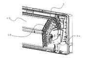
図4は、本発明の実施の形態1に係る熱交換器を示す分解斜視図である。図5〜図7は、この熱交換器の端部近傍を示す斜視図である。図8は、この熱交換器の端部近傍を示す正面図である。図9は、この熱交換器の端部近傍に設けられる塞ぎ部材を示す説明図である。また、図10は、この熱交換器の端部近傍に塞ぎ部材が設けられた状態を示す要部拡大図である。なお、図6は、図4に示す熱交換器20を裏側から見た状態を示している。また、図9は、図9(b)が塞ぎ部材の正面図を示し、図9(a)が図9(b)に示す塞ぎ部材を左側から見た斜視図を示し、図9(c)が図9(b)に示す塞ぎ部材を右側から見た斜視図を示している。
以下、これら図4〜図10を用いて、熱交換器20の端部近傍の詳細形状について説明する。
FIG. 4 is an exploded perspective view showing the heat exchanger according to Embodiment 1 of the present invention. 5 to 7 are perspective views showing the vicinity of the end of the heat exchanger. FIG. 8 is a front view showing the vicinity of the end of the heat exchanger. FIG. 9 is an explanatory view showing a closing member provided in the vicinity of the end of the heat exchanger. Moreover, FIG. 10 is a principal part enlarged view which shows the state by which the closing member was provided in the edge part vicinity of this heat exchanger. In addition, FIG. 6 has shown the state which looked at the heat exchanger 20 shown in FIG. 4 from the back side. FIG. 9B is a front view of the closing member, FIG. 9A is a perspective view of the closing member shown in FIG. 9B viewed from the left side, and FIG. FIG. 10 shows a perspective view of the closing member shown in FIG.
Hereinafter, the detailed shape near the end of the heat exchanger 20 will be described with reference to FIGS. 4 to 10.

熱交換器の伝熱管の少なくとも一方の端部は、冷媒流路を合流・分岐するために、複雑に配管接続されることとなる。この配管接続を容易とするため、本実施の形態1に係る熱交換器20では、各伝熱管27(扁平管)の一方の端部に管継手28を接続している。この管継手28は、伝熱管27側の端部が扁平管状の伝熱管27に対応した扁平管形状となっており、伝熱管27側と反対側の端部が円管形状となっている。そして、管継手28の円管部分を円管29で接続することにより、各伝熱管27の冷媒流路を合流・分岐している。   At least one end of the heat transfer tube of the heat exchanger is complicatedly piped to join and branch the refrigerant flow path. In order to facilitate this pipe connection, in the heat exchanger 20 according to the first embodiment, a pipe joint 28 is connected to one end of each heat transfer tube 27 (flat tube). The pipe joint 28 has a flat tube shape in which the end portion on the heat transfer tube 27 side corresponds to the flat tubular heat transfer tube 27, and the end portion on the opposite side to the heat transfer tube 27 side has a circular tube shape. Then, by connecting the circular pipe portions of the pipe joint 28 with the circular pipe 29, the refrigerant flow paths of the heat transfer pipes 27 are joined and branched.

また、熱交換器20の端部に設けられる固定部材30は、固定部材30に形成された開口部に伝熱管23(円管)の端部及び管継手28の円管部分を挿入し、これら伝熱管23及び管継手28の円管部分を拡管することにより、熱交換器20の端部に固定される。なお、図4に示すように、本実施の形態1では固定部材30を複数の固定部材(固定部材31〜35)で構成しているが、固定部材30を1つの固定部材として一体形成しても勿論よい。   Further, the fixing member 30 provided at the end of the heat exchanger 20 inserts the end of the heat transfer tube 23 (circular tube) and the circular pipe portion of the pipe joint 28 into the opening formed in the fixing member 30. By expanding the circular pipe portions of the heat transfer pipe 23 and the pipe joint 28, the pipe is fixed to the end of the heat exchanger 20. As shown in FIG. 4, in the first embodiment, the fixing member 30 is composed of a plurality of fixing members (fixing members 31 to 35). However, the fixing member 30 is integrally formed as one fixing member. Of course.

ここで、伝熱管27(扁平管)の一方の端部には管継手28が接続されるため、この接続箇所は、伝熱管27とは外形寸法が異なり、各伝熱管27に設けられるフィン26を取り付けることができない。このため、伝熱管27(扁平管)の管継手28が接続された側の端部において、熱交換器25は、固定部材30とフィン26との間隔が大きくなってしまう。このため、熱交換器25が蒸発器として機能する冷房運転時、固定部材30とフィン26との間を通った空気が、室内機100の風路へ浸入することとなる。   Here, since a pipe joint 28 is connected to one end portion of the heat transfer tube 27 (flat tube), the connecting portion has a different external dimension from the heat transfer tube 27, and the fin 26 provided in each heat transfer tube 27. Can not be installed. For this reason, in the end portion of the heat transfer tube 27 (flat tube) on the side where the pipe joint 28 is connected, in the heat exchanger 25, the interval between the fixing member 30 and the fin 26 is increased. For this reason, during the cooling operation in which the heat exchanger 25 functions as an evaporator, the air that has passed between the fixing member 30 and the fins 26 enters the air path of the indoor unit 100.

冷房運転時、固定部材30とフィン26との間を通った空気が室内機100の風路へ浸入すると、固定部材30とフィン26との間を通った空気(フィン26で熱交換していない空気)がフィン26の間を通った空気(フィン26で熱交換した空気)と室内機100の風路で混合されることとなる。これらの空気が室内機100の風路で混合してしまうと、室内機100の風路や送風機10等に着露し、露飛びが発生することが懸念される。また、冷房運転時、固定部材30とフィン26との間を通った空気が室内機100の風路へ浸入する際、管継手28に付着した露がフィン26を伝わらずに(露回収機構で回収されずに)室内機100の風路へ浸入し、露飛びが発生することが懸念される。   During the cooling operation, when the air that has passed between the fixed member 30 and the fins 26 enters the air passage of the indoor unit 100, the air that has passed between the fixed member 30 and the fins 26 (heat is not exchanged by the fins 26). Air) is mixed in the air passed between the fins 26 (air exchanged with the fins 26) and the air path of the indoor unit 100. If these airs are mixed in the air passage of the indoor unit 100, there is a concern that the air will be dewed on the air passage of the indoor unit 100, the blower 10 and the like, and dew may be generated. Further, during the cooling operation, when the air passing between the fixing member 30 and the fin 26 enters the air passage of the indoor unit 100, the dew adhering to the pipe joint 28 does not travel through the fin 26 (by the dew collecting mechanism). There is a concern that the air will enter the air passage of the indoor unit 100 (without being collected) and dew may occur.

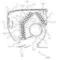
そこで、本実施の形態1では、固定部材30とフィン26との間の風下側に塞ぎ部材40を設けることにより、固定部材30とフィン26との間を通った空気が室内機100の風路へ浸入することを防止している。つまり、固定部材30とフィン26との間の風下側に塞ぎ部材40を設けることにより、室内機100の風路や送風機10等への着露に起因する露飛びや、管継手28に付着した露に起因する露飛びを防止している。ここで、塞ぎ部材40が本発明における第1の塞ぎ部材に相当する。   Therefore, in the first embodiment, by providing the closing member 40 on the leeward side between the fixing member 30 and the fin 26, the air passing between the fixing member 30 and the fin 26 is the air path of the indoor unit 100. To prevent intrusion. That is, by providing the closing member 40 on the leeward side between the fixing member 30 and the fins 26, dew caused by dew condensation on the air path of the indoor unit 100, the blower 10, and the like, or adhered to the pipe joint 28. Prevents dew escaping due to dew. Here, the closing member 40 corresponds to the first closing member in the present invention.

塞ぎ部材40は、例えば樹脂製であり、ベース41、突出部42、リブ43及びリブ44を備えている。ベース41は、例えば平板形状をしており、固定部材30の内面側(フィン26と対向する側)に取り付けられるものである。本実施の形態1では、例えばアルミニウム製のねじで、ベース41を固定部材30に固定している。ベース41の両端部には係止部材41aが設けられており、これら係止部材41aは、熱交換器20a及び熱交換器20cに設けられた管継手28に係止される。突出部42は、ベース41の例えば周縁部からフィン26に向かって突設されている。突出部42は、風下側において、固定部材30とフィン26との間を覆う形状となっている。また、突出部42の端部42aは、露回収機構の近傍まで延設されている。   The closing member 40 is made of, for example, resin, and includes a base 41, a protruding portion 42, a rib 43, and a rib 44. The base 41 has a flat plate shape, for example, and is attached to the inner surface side (side facing the fins 26) of the fixing member 30. In the first embodiment, the base 41 is fixed to the fixing member 30 with, for example, an aluminum screw. Locking members 41a are provided at both ends of the base 41, and these locking members 41a are locked to the pipe joints 28 provided in the heat exchanger 20a and the heat exchanger 20c. The protruding portion 42 protrudes from, for example, the peripheral portion of the base 41 toward the fin 26. The protruding portion 42 has a shape that covers between the fixing member 30 and the fin 26 on the leeward side. Further, the end portion 42a of the protruding portion 42 extends to the vicinity of the dew recovery mechanism.

リブ43は、突出部42の例えば端部から風上側(管継手28側)へ突設されている。リブ43の上端部は、フィン26と対向配置されている。また、フィン26とリブ43との間での流動抵抗を増加させつつ両者が接触しないように、フィン26とリブ43との間にはわずかな間隙が形成されている。ここで、リブ43が、本発明における第2のリブに相当する。リブ43を設けることにより、管継手28に付着した露を、固定部材30、突出部42及びリブ43で形成される溝部で回収し、露回収機構へ導くことができる。また、リブ43とフィン26とが接触していないので、リブ43が冷やされて着露することを防止できる。   The rib 43 protrudes from, for example, an end portion of the protruding portion 42 toward the windward side (the pipe joint 28 side). An upper end portion of the rib 43 is disposed to face the fin 26. In addition, a slight gap is formed between the fin 26 and the rib 43 so that the flow resistance between the fin 26 and the rib 43 is increased and the two do not contact each other. Here, the rib 43 corresponds to the second rib in the present invention. By providing the rib 43, dew adhering to the pipe joint 28 can be collected by the groove formed by the fixing member 30, the protruding portion 42, and the rib 43 and guided to the dew collecting mechanism. Further, since the ribs 43 and the fins 26 are not in contact with each other, the ribs 43 can be prevented from being cooled and dewed.

リブ44は、フィン26の風下側端部26aと対向するように、リブ43から延設されている。また、フィン26とリブ44との間での流動抵抗を増加させつつ両者が接触しないように、フィン26の風下側端部26aとリブ43との間にはわずかな間隙が形成されている。ここで、リブ44が本発明における第1のリブに相当する。リブ44とフィン26とが接触していないので、リブ44が冷やされて着露することを防止できる。   The rib 44 extends from the rib 43 so as to face the leeward side end portion 26 a of the fin 26. Further, a slight gap is formed between the leeward side end portion 26a of the fin 26 and the rib 43 so that the flow resistance between the fin 26 and the rib 44 is increased while the two do not come into contact with each other. Here, the rib 44 corresponds to the first rib in the present invention. Since the ribs 44 and the fins 26 are not in contact with each other, the ribs 44 can be prevented from being cooled and dewed.

以上、このように構成された室内機100及びこの室内機100を備えた空気調和機においては、固定部材30とフィン26との間の風下側に塞ぎ部材40を設けているので、フィン26で熱交換していない空気が室内機100の風路へ浸入することを防止できる。このため、冷房運転時、固定部材30とフィン26との間を通った空気(フィン26で熱交換していない空気)がフィン26の間を通った空気(フィン26で熱交換した空気)と室内機100の風路で混合されることを防止でき、室内機100の風路や送風機10等に着露して露飛びが発生することを防止できる。また、冷房運転時、管継手28に付着した露が室内機100の風路へ浸入して露飛びが発生することを防止できる。   As described above, in the indoor unit 100 configured as described above and the air conditioner including the indoor unit 100, the closing member 40 is provided on the leeward side between the fixed member 30 and the fin 26. It is possible to prevent air that has not been subjected to heat exchange from entering the air path of the indoor unit 100. For this reason, during the cooling operation, the air that passes between the fixing member 30 and the fins 26 (air that is not heat-exchanged by the fins 26) and the air that passes between the fins 26 (air that is heat-exchanged by the fins 26) and Mixing in the air path of the indoor unit 100 can be prevented, and it is possible to prevent the dew from occurring due to dew condensation on the air path of the indoor unit 100, the blower 10, and the like. Further, it is possible to prevent dew adhering to the pipe joint 28 from entering the air passage of the indoor unit 100 and causing dew jumping during the cooling operation.

また、塞ぎ部材40にリブ43を設けることにより、管継手28に付着した露を、固定部材30、突出部42及びリブ43で形成される溝部で回収し、露回収機構へ導くことができる。また、塞ぎ部材40にリブ43を設けることにより、フィン26とリブ43との間での流動抵抗を増加させることができ、フィン26で熱交換していない空気が室内機100の風路へ浸入することをより確実に防止できる。
また、塞ぎ部材40にリブ44を設けることにより、フィン26とリブ44との間での流動抵抗を増加させることができ、フィン26で熱交換していない空気が室内機100の風路へ浸入することをより確実に防止できる。
Further, by providing the rib 43 on the closing member 40, the dew adhering to the pipe joint 28 can be collected by the groove formed by the fixing member 30, the projecting portion 42 and the rib 43 and guided to the dew collecting mechanism. Further, by providing the rib 43 on the closing member 40, the flow resistance between the fin 26 and the rib 43 can be increased, and air not heat exchanged by the fin 26 enters the air path of the indoor unit 100. This can be prevented more reliably.
Moreover, by providing the rib 44 in the closing member 40, the flow resistance between the fin 26 and the rib 44 can be increased, and air that has not exchanged heat with the fin 26 enters the air passage of the indoor unit 100. This can be prevented more reliably.

また、このように構成された室内機100及びこの室内機100を備えた空気調和機においては、筐体1を従来の円管状伝熱管を用いた室内機の筐体と共通化することも可能となる。つまり、本実施の形態1に係る固定部材30として従来の室内機に搭載された熱交換器の固定部材を用いることにより、円管状伝熱管を用いた室内機の筐体に、熱交換効率の高い本実施の形態1に係る熱交換器20(扁平管状の伝熱管27を用いた熱交換器)を搭載することが可能となる。このため、円管29の配管構成を決定する際、従来と同じ設計思想で設計することが可能となる。また、設計にかかるコストや負荷を大きく低減することができる。   Further, in the indoor unit 100 configured as described above and the air conditioner including the indoor unit 100, the casing 1 can be shared with the casing of the indoor unit using a conventional circular heat transfer tube. It becomes. That is, by using the fixing member of the heat exchanger mounted on the conventional indoor unit as the fixing member 30 according to the first embodiment, the heat exchange efficiency of the casing of the indoor unit using the tubular heat transfer tube is improved. It is possible to mount a high heat exchanger 20 (a heat exchanger using a flat tubular heat transfer tube 27) according to the first embodiment. For this reason, when determining the piping configuration of the circular pipe 29, it is possible to design with the same design concept as before. Moreover, the cost and load concerning a design can be reduced significantly.

なお、本実施の形態1に係る熱交換器20の各構成部材の材質は特に限定されないが、熱交換器20の各構成部材の材質を例えば次のようにしてもよい。扁平管状の伝熱管27をアルミニウムやアルミニウム合金等で製作する場合、管継手28や固定部材30等もアルミニウムやアルミニウム合金等で製作するとよい。これにより、異種金属同士の接触による電食によって伝熱管27に穴が開き、作動冷媒が漏洩することを防止することができる。   In addition, although the material of each structural member of the heat exchanger 20 which concerns on this Embodiment 1 is not specifically limited, For example, you may make the material of each structural member of the heat exchanger 20 as follows. When the flat tubular heat transfer tube 27 is made of aluminum, aluminum alloy, or the like, the pipe joint 28, the fixing member 30 or the like may be made of aluminum, aluminum alloy, or the like. Thereby, it can prevent that a hole opens in the heat exchanger tube 27 by the electric corrosion by the contact of dissimilar metals, and a working refrigerant leaks.

また、本実施の形態1で示した熱交換器20の構成はあくまでも一例であり、伝熱管23及び伝熱管27の列数や段数は任意である。例えば、図11のように、扁平管状の伝熱管27のみを用いて熱交換器20を構成してもよい。つまり、扁平管状の伝熱管27を用いた熱交換器25のみで熱交換器20を構成してもよい。
なお、本実施の形態1では、
(1)円管状の伝熱管23を用いた熱交換器21は、固定部材30の近傍までフィン22を配置することができる。このため、フィン22で熱交換して除湿した後の空気が固定部材30とフィン26との間を通ることになるので、管継手28に付着する露の量が減少する。
(2)フィン22及び伝熱管23によって管継手28の風上側を覆うことにより、熱交換器の意匠性が向上する。
等の効果も得られるため、扁平管状の伝熱管27を用いた熱交換器25の風上側に円管状の伝熱管23を用いた熱交換器21を配置して熱交換器20を構成している。
Moreover, the structure of the heat exchanger 20 shown in this Embodiment 1 is an example to the last, and the row | line number and the stage number of the heat exchanger tube 23 and the heat exchanger tube 27 are arbitrary. For example, as shown in FIG. 11, the heat exchanger 20 may be configured using only the flat tubular heat transfer tube 27. That is, you may comprise the heat exchanger 20 only with the heat exchanger 25 using the flat tubular heat exchanger tube 27. FIG.
In the first embodiment,
(1) In the heat exchanger 21 using the tubular heat transfer tube 23, the fins 22 can be arranged up to the vicinity of the fixing member 30. For this reason, since air after heat-exchanging with the fin 22 and dehumidifying passes between the fixing member 30 and the fin 26, the amount of dew adhering to the pipe joint 28 is reduced.
(2) The design of the heat exchanger is improved by covering the windward side of the pipe joint 28 with the fins 22 and the heat transfer tubes 23.
Therefore, the heat exchanger 20 is configured by arranging the heat exchanger 21 using the tubular heat transfer tube 23 on the windward side of the heat exchanger 25 using the flat tubular heat transfer tube 27. Yes.

実施の形態2.
扁平管状の伝熱管27のみを用いて熱交換器20を構成する場合、塞ぎ部材40の形状を例えば以下のようにしてもよい。なお、本実施の形態2において、特に記述しない項目については実施の形態1と同様とし、同一の機能や構成については同一の符号を用いて述べることとする。
Embodiment 2. FIG.
When the heat exchanger 20 is configured using only the flat tubular heat transfer tube 27, the shape of the closing member 40 may be set as follows, for example. In the second embodiment, items that are not particularly described are the same as those in the first embodiment, and the same functions and configurations are described using the same reference numerals.

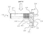
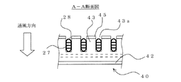
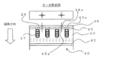
図12は、本発明の実施の形態2に係る熱交換器及び塞ぎ部材を示す要部拡大図である。また、図13は、図12のA−A断面図である。
図12及び図13に示すように、本実施の形態2に係る熱交換器20は、伝熱管として、扁平管状の伝熱管27のみを用いている。
FIG. 12 is an enlarged view of a main part showing a heat exchanger and a blocking member according to Embodiment 2 of the present invention. FIG. 13 is a cross-sectional view taken along the line AA in FIG.
As shown in FIGS. 12 and 13, the heat exchanger 20 according to the second embodiment uses only a flat tubular heat transfer tube 27 as a heat transfer tube.

本実施の形態2に係る塞ぎ部材40は、リブ43の端部が管継手28の風上側まで延設されている。そして、リブ43には、管継手28が挿入される(管継手28をかわすように)切欠き部43aが形成されている。切欠き部43aは、リブ43と熱交換器20とが接触しない寸法となっており、リブ43が冷やされて着露することを防止している。また、リブ43の端部には、固定部材30側へ突出したリブ45が設けられている。リブ45は、管継手28、固定部材30及びフィン26で囲まれた隙間を通過できる寸法となっている。ここで、リブ45が本発明における第3のリブに相当する。   In the closing member 40 according to the second embodiment, the end portion of the rib 43 extends to the windward side of the pipe joint 28. The rib 43 has a notch 43a into which the pipe joint 28 is inserted (so as to avoid the pipe joint 28). The notch 43a has a dimension such that the rib 43 and the heat exchanger 20 do not contact each other, and prevents the rib 43 from being cooled and dewed. A rib 45 protruding toward the fixing member 30 is provided at the end of the rib 43. The rib 45 is dimensioned to pass through a gap surrounded by the pipe joint 28, the fixing member 30 and the fin 26. Here, the rib 45 corresponds to the third rib in the present invention.

以上、このように構成された室内機100及びこの室内機100を備えた空気調和機においては、リブ45が設けられているので、固定部材30とフィン26との間を通る空気の量を抑制することができる。このため、冷房運転時、固定部材30とフィン26との間を通った空気(フィン26で熱交換していない空気)がフィン26の間を通った空気(フィン26で熱交換した空気)と室内機100の風路で混合されることをより防止でき、室内機100の風路や送風機10等に着露して露飛びが発生することをより防止できる。また、冷房運転時、管継手28に付着した露が室内機100の風路へ浸入して露飛びが発生することをより防止できる。   As described above, in the indoor unit 100 configured as described above and the air conditioner including the indoor unit 100, the rib 45 is provided, so that the amount of air passing between the fixed member 30 and the fin 26 is suppressed. can do. For this reason, during the cooling operation, the air that passes between the fixing member 30 and the fins 26 (air that is not heat-exchanged by the fins 26) and the air that passes between the fins 26 (air that is heat-exchanged by the fins 26) and Mixing in the air path of the indoor unit 100 can be further prevented, and it is possible to further prevent the occurrence of dew jumping due to dew condensation on the air path of the indoor unit 100, the blower 10 and the like. In addition, it is possible to further prevent dew adhering to the pipe joint 28 from entering the air passage of the indoor unit 100 and causing dew jumping during cooling operation.

また、リブ45は管継手28、固定部材30及びフィン26で囲まれた隙間を通過できる寸法となっているので、熱交換器20を組み立てた後に、塞ぎ部材40を熱交換器20の風下側から取り付けることができる。つまり、本実施の形態2に係る塞ぎ部材40は、熱交換器20に固定部材30を取り付けた後に、管継手28、固定部材30及びフィン26で囲まれた隙間にリブ45を通すことができる。このため、伝熱管27と管継手28との接続や管継手28と円管29との接続をロウ付けで行う場合でも、塞ぎ部材40がロウ付け時の高温下に晒されることを防止できる。したがって、塞ぎ部材を樹脂で形成することが可能となる。   Further, since the rib 45 is dimensioned to pass through the gap surrounded by the pipe joint 28, the fixing member 30 and the fin 26, after assembling the heat exchanger 20, the closing member 40 is connected to the leeward side of the heat exchanger 20. Can be attached from. That is, the closing member 40 according to the second embodiment can pass the rib 45 through the gap surrounded by the pipe joint 28, the fixing member 30, and the fins 26 after attaching the fixing member 30 to the heat exchanger 20. . For this reason, even when the connection between the heat transfer tube 27 and the pipe joint 28 and the connection between the pipe joint 28 and the circular pipe 29 are performed by brazing, the closing member 40 can be prevented from being exposed to high temperatures during brazing. Therefore, the closing member can be formed of resin.

なお、リブ45は、必ずしも管継手28の風上側に配置されなければならないことはない。隣接する管継手28の間にリブ45を配置してもよいし、管継手28よりも風下側にリブ45を配置してもよい。つまり、固定部材30とフィン26との間を通る空気の量を抑制することができれば、リブ45の位置は任意である。   The rib 45 does not necessarily have to be disposed on the windward side of the pipe joint 28. The ribs 45 may be arranged between the adjacent pipe joints 28, or the ribs 45 may be arranged on the leeward side of the pipe joints 28. That is, the position of the rib 45 is arbitrary as long as the amount of air passing between the fixing member 30 and the fin 26 can be suppressed.

実施の形態3.
実施の形態2に係る塞ぎ部材40に次のような板部材を設けることにより、露飛びの発生をより防止することが可能となる。なお、本実施の形態3において、特に記述しない項目については実施の形態1又は実施の形態2と同様とし、同一の機能や構成については同一の符号を用いて述べることとする。
Embodiment 3 FIG.
By providing the following plate member to the closing member 40 according to the second embodiment, it is possible to further prevent the occurrence of dew. In Embodiment 3, items that are not particularly described are the same as those in Embodiment 1 or Embodiment 2, and the same functions and configurations are described using the same reference numerals.

図14は、本発明の実施の形態3に係る熱交換器及び塞ぎ部材を示す要部拡大図である。また、図15は、図14のB−B断面図である。   FIG. 14 is an enlarged view of a main part showing a heat exchanger and a blocking member according to Embodiment 3 of the present invention. FIG. 15 is a sectional view taken along line BB in FIG.

本実施の形態3に係る熱交換器20及び塞ぎ部材40の形状は、実施の形態2と同じ形状となっている。しかしながら、本実施の形態3では、塞ぎ部材40のリブ45に板状部材46が設けられている。この板状部材46は、風上側において、固定部材30とフィン26との間を覆う形状となっている。板状部材46には貫通孔46aが形成されており、塞ぎ部材40のリブ45には貫通孔46aと対応する位置にねじ穴45aが形成されている。貫通孔46aに挿入したねじをねじ穴45aに螺入することで、板状部材46は塞ぎ部材40のリブ45に固定されている。ここで、板状部材46が本発明における第2の塞ぎ部材に相当する。   The shape of the heat exchanger 20 and the closing member 40 according to the third embodiment is the same as that of the second embodiment. However, in the third embodiment, the plate-like member 46 is provided on the rib 45 of the closing member 40. The plate-like member 46 has a shape that covers the space between the fixing member 30 and the fins 26 on the windward side. A through hole 46 a is formed in the plate member 46, and a screw hole 45 a is formed in the rib 45 of the closing member 40 at a position corresponding to the through hole 46 a. The plate-like member 46 is fixed to the rib 45 of the closing member 40 by screwing the screw inserted into the through hole 46 a into the screw hole 45 a. Here, the plate-like member 46 corresponds to the second closing member in the present invention.

以上、このように構成された室内機100及びこの室内機100を備えた空気調和機においては、実施の形態2と比べ、固定部材30とフィン26との間を通る空気の量をさらに抑制することができる。このため、冷房運転時、固定部材30とフィン26との間を通った空気(フィン26で熱交換していない空気)がフィン26の間を通った空気(フィン26で熱交換した空気)と室内機100の風路で混合されることをさらに防止でき、室内機100の風路や送風機10等に着露して露飛びが発生することをさらに防止できる。また、冷房運転時、管継手28に付着した露が室内機100の風路へ浸入して露飛びが発生することをさらに防止できる。   As described above, in the indoor unit 100 configured as described above and the air conditioner including the indoor unit 100, the amount of air passing between the fixed member 30 and the fins 26 is further suppressed as compared with the second embodiment. be able to. For this reason, during the cooling operation, the air that passes between the fixing member 30 and the fins 26 (air that is not heat-exchanged by the fins 26) and the air that passes between the fins 26 (air that is heat-exchanged by the fins 26) and Mixing in the air path of the indoor unit 100 can be further prevented, and it is possible to further prevent the occurrence of dew jumping due to dew condensation on the air path of the indoor unit 100, the blower 10 and the like. In addition, it is possible to further prevent dew adhering to the pipe joint 28 from entering the air passage of the indoor unit 100 and causing dew jumping during cooling operation.

また、板状部材46によって管継手28の風上側を覆うことにより、熱交換器の意匠性も向上する。   Further, by covering the windward side of the pipe joint 28 with the plate-like member 46, the design of the heat exchanger is also improved.

実施の形態4.
複数列に配置された伝熱管27が千鳥状に配置されている場合や、実施の形態1に示したように熱交換器20が断面視略コの字形状となっている場合等、リブ43を管継手28の間に挿入できず、実施の形態3で示した第2の塞ぎ部材(板状部材46)を設けることができない場合がある。また、実施の形態3で示した第2の塞ぎ部材を設けることができても、伝熱管27の配列が制限される場合がある。また、実施の形態3で示した第2の塞ぎ部材を設けることができても、伝熱管27の配列を変更する毎に塞ぎ部材40の形状を変更する必要が生じる場合がある。このような場合、第2の塞ぎ部材を例えば次のように構成してもよい。なお、本実施の形態4において、特に記述しない項目については実施の形態1〜実施の形態3と同様とし、同一の機能や構成については同一の符号を用いて述べることとする。
Embodiment 4 FIG.
When the heat transfer tubes 27 arranged in a plurality of rows are arranged in a staggered manner, or when the heat exchanger 20 has a substantially U-shape in cross section as shown in the first embodiment, the rib 43 Cannot be inserted between the pipe joints 28, and the second closing member (plate member 46) shown in the third embodiment may not be provided. Even if the second closing member shown in the third embodiment can be provided, the arrangement of the heat transfer tubes 27 may be limited. Even if the second closing member shown in the third embodiment can be provided, it may be necessary to change the shape of the closing member 40 every time the arrangement of the heat transfer tubes 27 is changed. In such a case, the second closing member may be configured as follows, for example. In the fourth embodiment, items not particularly described are the same as those in the first to third embodiments, and the same functions and configurations are described using the same reference numerals.

図16は、本発明の実施の形態4に係る熱交換器及び塞ぎ部材を示す要部拡大図である。また、図17は、本発明の実施の形態4に係る第2の塞ぎ部材を示す説明図である。
本実施の形態4に係る熱交換器20は、伝熱管27が例えば千鳥状に2列に配置されている。
FIG. 16 is an enlarged view of a main part showing a heat exchanger and a blocking member according to Embodiment 4 of the present invention. FIG. 17 is an explanatory diagram showing a second closing member according to the fourth embodiment of the present invention.
In the heat exchanger 20 according to the fourth embodiment, the heat transfer tubes 27 are arranged in, for example, two rows in a staggered manner.

このような場合、実施の形態3で示したような第2の塞ぎ部材(板状部材46)を設けることは困難である。そこで、本実施の形態4では、第1の塞ぎ部材として、実施の形態1で示した塞ぎ部材40を設けている。つまり、本実施の形態4では、実施の形態1で示した塞ぎ部材40を用い、固定部材30とフィン26との間の風下側を覆っている。そして、第2の塞ぎ部材として塞ぎ部材47を設け、固定部材30とフィン26との間の風上側を覆っている。   In such a case, it is difficult to provide the second closing member (plate member 46) as shown in the third embodiment. Therefore, in the fourth embodiment, the blocking member 40 shown in the first embodiment is provided as the first blocking member. That is, in the fourth embodiment, the closing member 40 shown in the first embodiment is used to cover the leeward side between the fixing member 30 and the fins 26. A closing member 47 is provided as a second closing member, and covers the windward side between the fixing member 30 and the fins 26.

この塞ぎ部材47は、断面視略コの字状に形成されている。塞ぎ部材47の一方の端部側には貫通孔47bが形成されており、固定部材30には貫通孔47bと対応する位置にねじ穴30aが形成されている。貫通孔47bに挿入したねじをねじ穴30aに螺入することで、塞ぎ部材47は固定部材30に固定されている。また、塞ぎ部材47の他方の端部には、伝熱管27が挿入される(伝熱管27をかわすように)切欠き部47aが形成されている。塞ぎ部材47は、この他方の端部がフィン26の間に食い込むように、設けられている。   The closing member 47 is formed in a substantially U shape in a sectional view. A through hole 47b is formed on one end side of the closing member 47, and a screw hole 30a is formed in the fixing member 30 at a position corresponding to the through hole 47b. The closing member 47 is fixed to the fixing member 30 by screwing the screw inserted into the through hole 47b into the screw hole 30a. Further, a cutout portion 47 a into which the heat transfer tube 27 is inserted (so as to avoid the heat transfer tube 27) is formed at the other end portion of the closing member 47. The closing member 47 is provided such that the other end bites between the fins 26.

以上、このように構成された室内機100及びこの室内機100を用いた空気調和機においては、熱交換器20の構成(伝熱管27の配列や熱交換器20の形状等)が制限されることがなく、塞ぎ部材47により固定部材30とフィン26との間の風上側を覆うことができる。   As described above, in the indoor unit 100 configured as described above and the air conditioner using the indoor unit 100, the configuration of the heat exchanger 20 (such as the arrangement of the heat transfer tubes 27 and the shape of the heat exchanger 20) is limited. The closing member 47 can cover the windward side between the fixing member 30 and the fin 26.

なお、塞ぎ部材47を取り付ける部材は固定部材30に限定されるものではない。塞ぎ部材47を熱交換器20の風上側から設置して固定できれば、塞ぎ部材47を取り付ける部材は任意である。   The member for attaching the closing member 47 is not limited to the fixing member 30. As long as the closing member 47 can be installed and fixed from the windward side of the heat exchanger 20, the member to which the closing member 47 is attached is arbitrary.

1 筐体、1a 吸込口、1b 吹出口、2 ボックス、2a 保持板、2b リブ、3 前面枠、4 前面開閉パネル、5 ノズル、6 風向き調整機構、6a 上下方向ベーン、7 フィルター、8 電気品ボックス、10 送風機、11 ブレード、20(20a〜20c) 熱交換器、21 熱交換器、22 フィン、23 伝熱管(円管)、25 熱交換器、26 フィン、27 伝熱管(扁平管)、28 管継手、29 円管、30 固定部材、30a ねじ穴、31〜35 固定部材、40 塞ぎ部材、41 ベース、41a 係止部材、42 突出部、43 リブ、43a 切欠き部、44 リブ、45 リブ、45a ねじ穴、46 板状部材、46a 貫通孔、47 塞ぎ部材、47a 切欠き部、47b 貫通孔、100 室内機。   DESCRIPTION OF SYMBOLS 1 Case, 1a Suction port, 1b Air outlet, 2 box, 2a Holding plate, 2b rib, 3 Front frame, 4 Front opening / closing panel, 5 Nozzle, 6 Wind direction adjustment mechanism, 6a Vertical vane, 7 Filter, 8 Electrical goods Box, 10 blower, 11 blade, 20 (20a to 20c) heat exchanger, 21 heat exchanger, 22 fin, 23 heat transfer tube (circular tube), 25 heat exchanger, 26 fin, 27 heat transfer tube (flat tube), 28 pipe joint, 29 circular pipe, 30 fixing member, 30a screw hole, 31-35 fixing member, 40 closing member, 41 base, 41a locking member, 42 protrusion, 43 rib, 43a notch, 44 rib, 45 Rib, 45a Screw hole, 46 Plate member, 46a Through hole, 47 Closing member, 47a Notch, 47b Through hole, 100 Indoor unit.

Claims (8)

吹出口及び吸込口が形成された筐体と、該筐体に収容された熱交換器と、を備え、
前記熱交換器は該熱交換器の両端部に設けられた固定部材を介して前記筐体に取り付けられ、これら固定部材の間に風路が形成される空気調和機の室内機であって、
前記熱交換器は、所定の間隙を介して配置された複数の第1のフィンと、該第1のフィンを貫通して設けられた複数の扁平管と、を備え、
該扁平管の少なくとも一方の端部には、該扁平管側と反対側の端部が円管形状で、前記固定部材に固定された管継手が設けられ、
該管継手の風下側には、前記第1のフィンと前記固定部材との間の風路を塞ぐ第1の塞ぎ部材が設けられており、
前記第1の塞ぎ部材は、風上側へ突設された第2のリブを備え、
前記第2のリブは、前記管継手が挿入される切欠き部が形成され、
前記第2のリブの風上側端部に、当該管継手が固定された前記固定部材側へ突設された第3のリブを備えたことを特徴とする空気調和機の室内機。
A housing in which the air outlet and the suction port are formed, and a heat exchanger accommodated in the housing,
The heat exchanger is an indoor unit of an air conditioner that is attached to the housing via fixing members provided at both ends of the heat exchanger, and an air passage is formed between the fixing members,
The heat exchanger includes a plurality of first fins arranged via a predetermined gap, and a plurality of flat tubes provided through the first fins,
At least one end portion of the flat tube is provided with a pipe joint fixed to the fixing member in an end portion on the opposite side to the flat tube side in a circular tube shape,
On the leeward side of the pipe joint, a first closing member for closing an air passage between the first fin and the fixing member is provided ,
The first closing member includes a second rib protruding to the windward side,
The second rib is formed with a notch into which the pipe joint is inserted,
An air conditioner indoor unit comprising a third rib projecting toward the fixing member to which the pipe joint is fixed at the windward end of the second rib .
前記第3のリブは前記管継手よりも風上側に配置され、
該第3のリブに、前記第1のフィンと前記固定部材との間の風路を塞ぐ第2の塞ぎ部材が設けられていることを特徴とする請求項に記載の空気調和機の室内機。
The third rib is disposed on the windward side of the pipe joint,
2. The air conditioner room according to claim 1 , wherein the third rib is provided with a second blocking member that blocks an air passage between the first fin and the fixing member. Machine.
吹出口及び吸込口が形成された筐体と、該筐体に収容された熱交換器と、を備え、
前記熱交換器は該熱交換器の両端部に設けられた固定部材を介して前記筐体に取り付けられ、これら固定部材の間に風路が形成される空気調和機の室内機であって、
前記熱交換器は、所定の間隙を介して配置された複数の第1のフィンと、該第1のフィンを貫通して設けられた複数の扁平管と、を備え、
該扁平管の少なくとも一方の端部には、該扁平管側と反対側の端部が円管形状で、前記固定部材に固定された管継手が設けられ、
該管継手の風下側には、前記第1のフィンと前記固定部材との間の風路を塞ぐ第1の塞ぎ部材が設けられており、
前記熱交換器は、所定の間隙を介して配置された複数の第2のフィンと、該第2のフィンを貫通して設けられた複数の円管と、をさらに備え、
該円管及び前記第2のフィンは前記扁平管及び前記第1のフィンの風上側に配置され、かつ、前記第2のフィンは前記管継手の風上側を覆うように配置されていることを特徴とする空気調和機の室内機。
A housing in which the air outlet and the suction port are formed, and a heat exchanger accommodated in the housing,
The heat exchanger is an indoor unit of an air conditioner that is attached to the housing via fixing members provided at both ends of the heat exchanger, and an air passage is formed between the fixing members,
The heat exchanger includes a plurality of first fins arranged via a predetermined gap, and a plurality of flat tubes provided through the first fins,
At least one end portion of the flat tube is provided with a pipe joint fixed to the fixing member in an end portion on the opposite side to the flat tube side in a circular tube shape,
On the leeward side of the pipe joint, a first closing member for closing an air passage between the first fin and the fixing member is provided ,
The heat exchanger further includes a plurality of second fins arranged via a predetermined gap, and a plurality of circular tubes provided through the second fins,
The circular pipe and the second fin are disposed on the windward side of the flat tube and the first fin, and the second fin is disposed so as to cover the windward side of the pipe joint. An air conditioner indoor unit.
前記管継手よりも風上側に配置され、前記第1のフィンと前記固定部材との間の風路を塞ぐ第2の塞ぎ部材が設けられていることを特徴とする請求項に記載の空気調和機の室内機。 4. The air according to claim 3 , wherein a second closing member that is disposed on the windward side of the pipe joint and blocks an air path between the first fin and the fixing member is provided. 5. The indoor unit of the harmony machine. 前記管継手は、該管継手の円管形状の部分が拡管されることにより、前記固定部材に固定されていることを特徴とする請求項1〜請求項4のいずれか一項に記載の空気調和機の室内機。 The air according to any one of claims 1 to 4, wherein the pipe joint is fixed to the fixing member by expanding a circular pipe-shaped portion of the pipe joint. The indoor unit of the harmony machine. 前記第1の塞ぎ部材は、前記第1のフィンの少なくとも一部の風下側端面部と対向して配置される第1のリブが突設されていることを特徴とする請求項1〜請求項5のいずれか一項に記載の空気調和機の室内機。 Wherein the first closing member, according to claim 1 claims, characterized in that the first rib that is disposed opposite to the at least a portion of the leeward side end face portion of the first fin is projected The indoor unit of the air conditioner according to any one of 5 . 前記扁平管に流れる冷媒としてR32が用いられることを特徴とする請求項1〜請求項のいずれか一項に記載の空気調和機の室内機。 The indoor unit of the air conditioner according to any one of claims 1 to 6 , wherein R32 is used as a refrigerant flowing through the flat tube. 請求項1〜請求項のいずれか一項に記載の空気調和機の室内機を備えたことを特徴とする空気調和機。 An air conditioner comprising the air conditioner indoor unit according to any one of claims 1 to 7 .
JP2010147166A 2010-06-29 2010-06-29 Air conditioner indoor unit and air conditioner equipped with the indoor unit Expired - Fee Related JP5455817B2 (en)

Priority Applications (1)

Application Number Priority Date Filing Date Title
JP2010147166A JP5455817B2 (en) 2010-06-29 2010-06-29 Air conditioner indoor unit and air conditioner equipped with the indoor unit

Applications Claiming Priority (1)

Application Number Priority Date Filing Date Title
JP2010147166A JP5455817B2 (en) 2010-06-29 2010-06-29 Air conditioner indoor unit and air conditioner equipped with the indoor unit

Publications (3)

Publication Number Publication Date
JP2012013244A JP2012013244A (en) 2012-01-19
JP2012013244A5 JP2012013244A5 (en) 2012-08-09
JP5455817B2 true JP5455817B2 (en) 2014-03-26

Family

ID=45599898

Family Applications (1)

Application Number Title Priority Date Filing Date
JP2010147166A Expired - Fee Related JP5455817B2 (en) 2010-06-29 2010-06-29 Air conditioner indoor unit and air conditioner equipped with the indoor unit

Country Status (1)

Country Link
JP (1) JP5455817B2 (en)

Families Citing this family (1)

* Cited by examiner, † Cited by third party
Publication number Priority date Publication date Assignee Title
JP6771321B2 (en) * 2016-06-27 2020-10-21 日立ジョンソンコントロールズ空調株式会社 Indoor unit of air conditioner

Family Cites Families (7)

* Cited by examiner, † Cited by third party
Publication number Priority date Publication date Assignee Title
JPH0646158B2 (en) * 1986-06-23 1994-06-15 昭和アルミニウム株式会社 Heat exchanger
JP3280868B2 (en) * 1996-10-08 2002-05-13 三菱電機株式会社 Indoor unit of air conditioner
JP4080352B2 (en) * 2003-02-26 2008-04-23 三菱電機株式会社 Fin tube heat exchanger manufacturing method and air conditioning refrigeration system
JP2005214448A (en) * 2004-01-27 2005-08-11 Toshiba Kyaria Kk Air conditioner
JP4504288B2 (en) * 2005-09-09 2010-07-14 リンナイ株式会社 Air conditioner
JP4749373B2 (en) * 2007-04-10 2011-08-17 三菱電機株式会社 Air conditioner
JP2010127426A (en) * 2008-11-28 2010-06-10 Mitsubishi Electric Corp Structure and method for joining aluminum flat pipe with copper pipe

Also Published As

Publication number Publication date
JP2012013244A (en) 2012-01-19

Similar Documents

Publication Publication Date Title
JP5422953B2 (en) Indoor unit for air conditioner
JP5618368B2 (en) Heat exchanger and integrated air conditioner equipped with the same
JP6223596B2 (en) Air conditioner indoor unit
JP4618254B2 (en) Shielding member and air conditioner indoor unit
JP4952347B2 (en) Air conditioner
JP5455817B2 (en) Air conditioner indoor unit and air conditioner equipped with the indoor unit
JP2901338B2 (en) Heat exchanger
JP5430527B2 (en) Air conditioner indoor unit and air conditioner equipped with the indoor unit
JP6661782B2 (en) Air conditioner outdoor unit
US20230164950A1 (en) Air conditioning apparatus and electric control box
JP2019074284A (en) Outdoor unit of air conditioner
JP6624851B2 (en) Air conditioner and its indoor unit
JP6400210B2 (en) Air conditioner indoor unit
JP6486718B2 (en) Heat exchanger
CN214275957U (en) Clean and small-sized vertical cabinet type indoor unit
JP7137092B2 (en) Heat exchanger
WO2024084832A1 (en) Flat pipe heat exchanger
CN102679793A (en) Heat exchanger fin
CN219624176U (en) Air conditioner outdoor unit
CN216897515U (en) Wall-mounted air conditioner
WO2023053553A1 (en) Indoor unit and air conditioner
US20230332776A1 (en) Indoor heat exchanger and indoor unit of air-conditioning apparatus
CN112781107A (en) Clean and small-sized vertical cabinet type indoor unit
JP2023104046A (en) Outdoor unit of air conditioner
JP5931470B2 (en) Heat exchange unit and air conditioner

Legal Events

Date Code Title Description
A521 Written amendment

Free format text: JAPANESE INTERMEDIATE CODE: A523

Effective date: 20120625

A621 Written request for application examination

Free format text: JAPANESE INTERMEDIATE CODE: A621

Effective date: 20120625

A977 Report on retrieval

Free format text: JAPANESE INTERMEDIATE CODE: A971007

Effective date: 20130605

A131 Notification of reasons for refusal

Free format text: JAPANESE INTERMEDIATE CODE: A131

Effective date: 20130611

A521 Written amendment

Free format text: JAPANESE INTERMEDIATE CODE: A523

Effective date: 20130801

TRDD Decision of grant or rejection written
A01 Written decision to grant a patent or to grant a registration (utility model)

Free format text: JAPANESE INTERMEDIATE CODE: A01

Effective date: 20131210

A61 First payment of annual fees (during grant procedure)

Free format text: JAPANESE INTERMEDIATE CODE: A61

Effective date: 20140107

R150 Certificate of patent or registration of utility model

Ref document number: 5455817

Country of ref document: JP

Free format text: JAPANESE INTERMEDIATE CODE: R150

Free format text: JAPANESE INTERMEDIATE CODE: R150

R250 Receipt of annual fees

Free format text: JAPANESE INTERMEDIATE CODE: R250

R250 Receipt of annual fees

Free format text: JAPANESE INTERMEDIATE CODE: R250

R250 Receipt of annual fees

Free format text: JAPANESE INTERMEDIATE CODE: R250

R250 Receipt of annual fees

Free format text: JAPANESE INTERMEDIATE CODE: R250

LAPS Cancellation because of no payment of annual fees