JP5450311B2 - Idle stop control method and control apparatus - Google Patents
Idle stop control method and control apparatus Download PDFInfo
- Publication number
- JP5450311B2 JP5450311B2 JP2010174989A JP2010174989A JP5450311B2 JP 5450311 B2 JP5450311 B2 JP 5450311B2 JP 2010174989 A JP2010174989 A JP 2010174989A JP 2010174989 A JP2010174989 A JP 2010174989A JP 5450311 B2 JP5450311 B2 JP 5450311B2
- Authority
- JP
- Japan
- Prior art keywords
- pinion
- ring gear
- engine
- rotation speed
- speed
- Prior art date
- Legal status (The legal status is an assumption and is not a legal conclusion. Google has not performed a legal analysis and makes no representation as to the accuracy of the status listed.)
- Active
Links
- 238000000034 method Methods 0.000 title description 19
- 230000001133 acceleration Effects 0.000 claims description 18
- 238000001514 detection method Methods 0.000 claims description 13
- 239000000446 fuel Substances 0.000 claims description 7
- 238000002347 injection Methods 0.000 claims description 5
- 239000007924 injection Substances 0.000 claims description 5
- 239000007858 starting material Substances 0.000 description 38
- 238000001125 extrusion Methods 0.000 description 10
- 238000002485 combustion reaction Methods 0.000 description 7
- 230000001360 synchronised effect Effects 0.000 description 5
- 238000004364 calculation method Methods 0.000 description 3
- 230000009191 jumping Effects 0.000 description 3
- 230000006835 compression Effects 0.000 description 2
- 238000007906 compression Methods 0.000 description 2
- 230000007423 decrease Effects 0.000 description 2
- 238000010586 diagram Methods 0.000 description 2
- 230000010349 pulsation Effects 0.000 description 2
- 238000011084 recovery Methods 0.000 description 2
- 230000000994 depressogenic effect Effects 0.000 description 1
- 238000005516 engineering process Methods 0.000 description 1
- -1 ignition Substances 0.000 description 1
- 238000004519 manufacturing process Methods 0.000 description 1
- 239000004065 semiconductor Substances 0.000 description 1
- 230000002123 temporal effect Effects 0.000 description 1
Images


Classifications
-
- F—MECHANICAL ENGINEERING; LIGHTING; HEATING; WEAPONS; BLASTING
- F02—COMBUSTION ENGINES; HOT-GAS OR COMBUSTION-PRODUCT ENGINE PLANTS
- F02N—STARTING OF COMBUSTION ENGINES; STARTING AIDS FOR SUCH ENGINES, NOT OTHERWISE PROVIDED FOR
- F02N11/00—Starting of engines by means of electric motors
- F02N11/08—Circuits or control means specially adapted for starting of engines
- F02N11/0851—Circuits or control means specially adapted for starting of engines characterised by means for controlling the engagement or disengagement between engine and starter, e.g. meshing of pinion and engine gear
- F02N11/0855—Circuits or control means specially adapted for starting of engines characterised by means for controlling the engagement or disengagement between engine and starter, e.g. meshing of pinion and engine gear during engine shutdown or after engine stop before start command, e.g. pre-engagement of pinion
-
- F—MECHANICAL ENGINEERING; LIGHTING; HEATING; WEAPONS; BLASTING
- F02—COMBUSTION ENGINES; HOT-GAS OR COMBUSTION-PRODUCT ENGINE PLANTS
- F02D—CONTROLLING COMBUSTION ENGINES
- F02D2200/00—Input parameters for engine control
- F02D2200/02—Input parameters for engine control the parameters being related to the engine
- F02D2200/10—Parameters related to the engine output, e.g. engine torque or engine speed
- F02D2200/1012—Engine speed gradient
-
- F—MECHANICAL ENGINEERING; LIGHTING; HEATING; WEAPONS; BLASTING
- F02—COMBUSTION ENGINES; HOT-GAS OR COMBUSTION-PRODUCT ENGINE PLANTS
- F02D—CONTROLLING COMBUSTION ENGINES
- F02D41/00—Electrical control of supply of combustible mixture or its constituents
- F02D41/24—Electrical control of supply of combustible mixture or its constituents characterised by the use of digital means
- F02D41/2406—Electrical control of supply of combustible mixture or its constituents characterised by the use of digital means using essentially read only memories
- F02D41/2409—Addressing techniques specially adapted therefor
- F02D41/2422—Selective use of one or more tables
-
- F—MECHANICAL ENGINEERING; LIGHTING; HEATING; WEAPONS; BLASTING
- F02—COMBUSTION ENGINES; HOT-GAS OR COMBUSTION-PRODUCT ENGINE PLANTS
- F02D—CONTROLLING COMBUSTION ENGINES
- F02D41/00—Electrical control of supply of combustible mixture or its constituents
- F02D41/24—Electrical control of supply of combustible mixture or its constituents characterised by the use of digital means
- F02D41/2406—Electrical control of supply of combustible mixture or its constituents characterised by the use of digital means using essentially read only memories
- F02D41/2425—Particular ways of programming the data
- F02D41/2429—Methods of calibrating or learning
- F02D41/2477—Methods of calibrating or learning characterised by the method used for learning
-
- F—MECHANICAL ENGINEERING; LIGHTING; HEATING; WEAPONS; BLASTING
- F02—COMBUSTION ENGINES; HOT-GAS OR COMBUSTION-PRODUCT ENGINE PLANTS
- F02N—STARTING OF COMBUSTION ENGINES; STARTING AIDS FOR SUCH ENGINES, NOT OTHERWISE PROVIDED FOR
- F02N11/00—Starting of engines by means of electric motors
- F02N11/08—Circuits or control means specially adapted for starting of engines
- F02N11/0814—Circuits or control means specially adapted for starting of engines comprising means for controlling automatic idle-start-stop
- F02N11/0844—Circuits or control means specially adapted for starting of engines comprising means for controlling automatic idle-start-stop with means for restarting the engine directly after an engine stop request, e.g. caused by change of driver mind
-
- F—MECHANICAL ENGINEERING; LIGHTING; HEATING; WEAPONS; BLASTING
- F02—COMBUSTION ENGINES; HOT-GAS OR COMBUSTION-PRODUCT ENGINE PLANTS
- F02N—STARTING OF COMBUSTION ENGINES; STARTING AIDS FOR SUCH ENGINES, NOT OTHERWISE PROVIDED FOR
- F02N15/00—Other power-operated starting apparatus; Component parts, details, or accessories, not provided for in, or of interest apart from groups F02N5/00 - F02N13/00
- F02N15/02—Gearing between starting-engines and started engines; Engagement or disengagement thereof
- F02N15/04—Gearing between starting-engines and started engines; Engagement or disengagement thereof the gearing including disengaging toothed gears
- F02N15/043—Gearing between starting-engines and started engines; Engagement or disengagement thereof the gearing including disengaging toothed gears the gearing including a speed reducer
-
- F—MECHANICAL ENGINEERING; LIGHTING; HEATING; WEAPONS; BLASTING
- F02—COMBUSTION ENGINES; HOT-GAS OR COMBUSTION-PRODUCT ENGINE PLANTS
- F02N—STARTING OF COMBUSTION ENGINES; STARTING AIDS FOR SUCH ENGINES, NOT OTHERWISE PROVIDED FOR
- F02N15/00—Other power-operated starting apparatus; Component parts, details, or accessories, not provided for in, or of interest apart from groups F02N5/00 - F02N13/00
- F02N15/02—Gearing between starting-engines and started engines; Engagement or disengagement thereof
- F02N15/04—Gearing between starting-engines and started engines; Engagement or disengagement thereof the gearing including disengaging toothed gears
- F02N15/06—Gearing between starting-engines and started engines; Engagement or disengagement thereof the gearing including disengaging toothed gears the toothed gears being moved by axial displacement
- F02N15/067—Gearing between starting-engines and started engines; Engagement or disengagement thereof the gearing including disengaging toothed gears the toothed gears being moved by axial displacement the starter comprising an electro-magnetically actuated lever
-
- F—MECHANICAL ENGINEERING; LIGHTING; HEATING; WEAPONS; BLASTING
- F02—COMBUSTION ENGINES; HOT-GAS OR COMBUSTION-PRODUCT ENGINE PLANTS
- F02N—STARTING OF COMBUSTION ENGINES; STARTING AIDS FOR SUCH ENGINES, NOT OTHERWISE PROVIDED FOR
- F02N2200/00—Parameters used for control of starting apparatus
- F02N2200/02—Parameters used for control of starting apparatus said parameters being related to the engine
- F02N2200/021—Engine crank angle
-
- F—MECHANICAL ENGINEERING; LIGHTING; HEATING; WEAPONS; BLASTING
- F02—COMBUSTION ENGINES; HOT-GAS OR COMBUSTION-PRODUCT ENGINE PLANTS
- F02N—STARTING OF COMBUSTION ENGINES; STARTING AIDS FOR SUCH ENGINES, NOT OTHERWISE PROVIDED FOR
- F02N2200/00—Parameters used for control of starting apparatus
- F02N2200/02—Parameters used for control of starting apparatus said parameters being related to the engine
- F02N2200/022—Engine speed
-
- F—MECHANICAL ENGINEERING; LIGHTING; HEATING; WEAPONS; BLASTING
- F02—COMBUSTION ENGINES; HOT-GAS OR COMBUSTION-PRODUCT ENGINE PLANTS
- F02N—STARTING OF COMBUSTION ENGINES; STARTING AIDS FOR SUCH ENGINES, NOT OTHERWISE PROVIDED FOR
- F02N2200/00—Parameters used for control of starting apparatus
- F02N2200/04—Parameters used for control of starting apparatus said parameters being related to the starter motor
- F02N2200/041—Starter speed
-
- F—MECHANICAL ENGINEERING; LIGHTING; HEATING; WEAPONS; BLASTING
- F02—COMBUSTION ENGINES; HOT-GAS OR COMBUSTION-PRODUCT ENGINE PLANTS
- F02N—STARTING OF COMBUSTION ENGINES; STARTING AIDS FOR SUCH ENGINES, NOT OTHERWISE PROVIDED FOR
- F02N2200/00—Parameters used for control of starting apparatus
- F02N2200/04—Parameters used for control of starting apparatus said parameters being related to the starter motor
- F02N2200/048—Information about pinion speed, both translational or rotational speed
-
- F—MECHANICAL ENGINEERING; LIGHTING; HEATING; WEAPONS; BLASTING
- F02—COMBUSTION ENGINES; HOT-GAS OR COMBUSTION-PRODUCT ENGINE PLANTS
- F02N—STARTING OF COMBUSTION ENGINES; STARTING AIDS FOR SUCH ENGINES, NOT OTHERWISE PROVIDED FOR
- F02N2300/00—Control related aspects of engine starting
- F02N2300/20—Control related aspects of engine starting characterised by the control method
- F02N2300/2006—Control related aspects of engine starting characterised by the control method using prediction of future conditions
-
- F—MECHANICAL ENGINEERING; LIGHTING; HEATING; WEAPONS; BLASTING
- F02—COMBUSTION ENGINES; HOT-GAS OR COMBUSTION-PRODUCT ENGINE PLANTS
- F02N—STARTING OF COMBUSTION ENGINES; STARTING AIDS FOR SUCH ENGINES, NOT OTHERWISE PROVIDED FOR
- F02N2300/00—Control related aspects of engine starting
- F02N2300/20—Control related aspects of engine starting characterised by the control method
- F02N2300/2011—Control involving a delay; Control involving a waiting period before engine stop or engine start
-
- F—MECHANICAL ENGINEERING; LIGHTING; HEATING; WEAPONS; BLASTING
- F02—COMBUSTION ENGINES; HOT-GAS OR COMBUSTION-PRODUCT ENGINE PLANTS
- F02N—STARTING OF COMBUSTION ENGINES; STARTING AIDS FOR SUCH ENGINES, NOT OTHERWISE PROVIDED FOR
- F02N99/00—Subject matter not provided for in other groups of this subclass
- F02N99/002—Starting combustion engines by ignition means
Description
本発明は、エンジンの停止と再始動を自動的に行うアイドルストップシステムに関する。 The present invention relates to an idle stop system that automatically stops and restarts an engine.
近年、エネルギ資源の節約と環境保全を目的とした自動車の技術が開発されている。例えば、運転中に所定の条件(自動停止条件)が成立した時に、エンジンに供給する燃料をカットし、エンジンが発生するトルクを失わせるアイドルストップシステムを搭載したものがある。自動停止条件は、運転者がアクセルから足を離したり、ブレーキを踏んだりすることで成立する。このアイドルストップシステムでは、車両が停止していなくても、自動停止条件が成立したらエンジンを自動的に停止する。その後、運転者の再始動要求が生じた時点や、エンジンの稼働が必要になった時にエンジンを再始動する。 In recent years, automobile technologies aimed at saving energy resources and protecting the environment have been developed. For example, there is a vehicle equipped with an idle stop system that cuts fuel supplied to an engine and loses torque generated by the engine when a predetermined condition (automatic stop condition) is satisfied during operation. The automatic stop condition is satisfied when the driver removes his or her foot from the accelerator or steps on the brake. In this idle stop system, even if the vehicle is not stopped, the engine is automatically stopped when the automatic stop condition is satisfied. Thereafter, the engine is restarted when a driver's restart request occurs or when the engine needs to be operated.
エンジンを再始動させる方法として、ピニオン押し出し式のスタータを用い、スタータのピニオンを押し出してそのピニオンをエンジンのリングギヤに噛み合わせ、スタータの回転をエンジンに伝えて、エンジンを回転させ、始動させる方法を採っているものがある。 As a method for restarting the engine, a method using a pinion push-out starter, pushes the pinion of the starter, meshes the pinion with the ring gear of the engine, transmits the rotation of the starter to the engine, rotates the engine and starts it. There is something that is taken.
エンジンが発生するトルクが失われた後の惰性回転中に、アクセルが踏み込まれるなどの条件が成立し、再始動要求が発生したときはスタータのモータへの通電を開始してピニオンを回転させ、ピニオンの回転速度がリングギヤの回転速度と同期した時点でピニオンをリングギヤに噛み込ませてスタータによるクランキングを開始することで、エンジン回転の復帰を早める方法が提案されている(特許文献1参照)。この文献では、エンジンの運動エネルギとエンジンの運動を妨げる仕事量とを演算し、将来の運動エネルギを予測することで将来のエンジン回転速度を予測する。 Conditions such as the accelerator being depressed during inertial rotation after the torque generated by the engine is lost, and when a restart request occurs, start energization of the starter motor and rotate the pinion, A method has been proposed in which when the rotation speed of the pinion synchronizes with the rotation speed of the ring gear, the pinion is engaged with the ring gear and cranking by the starter is started to speed up the recovery of the engine rotation (see Patent Document 1). . In this document, the kinetic energy of the engine and the work amount that hinders the movement of the engine are calculated, and the future kinetic energy is predicted to predict the future engine rotation speed.
ピニオン押し出し式のスタータは、ピニオンを押し出してリングギヤに到達するまでに遅れ時間があり、スムーズな噛み込みのためにピニオンがリングギヤに到達した時点でのエンジンの回転速度を予測する必要がある。しかし圧縮行程にある気筒が仕事をしてエネルギを消費するので、エンジンの回転速度は惰性回転中であっても脈動しながら減衰する。よって、将来のエンジン回転速度を予測するためには、脈動しながら減衰するエンジンの回転速度を正確に予測する必要がある。噛み込み時には歯と歯がぶつかり合い騒音が発生し、その時のピニオンとリングギヤの回転速度の速度差が騒音を大きく左右する。 The pinion extrusion type starter has a delay time until it reaches the ring gear after the pinion is pushed out, and it is necessary to predict the rotational speed of the engine when the pinion reaches the ring gear for smooth engagement. However, since the cylinders in the compression stroke work and consume energy, the rotational speed of the engine attenuates while pulsating even during inertial rotation. Therefore, in order to predict the future engine speed, it is necessary to accurately predict the engine speed that attenuates while pulsating. At the time of biting, the teeth collide with each other and noise is generated, and the difference in rotational speed between the pinion and the ring gear at that time greatly affects the noise.
本発明は、エンジンの惰性回転中にエンジンのリングギヤとスタータのピニオンギヤとを噛み合わせるときに生じる騒音を抑制することを目的とする。 An object of the present invention is to suppress noise generated when an engine ring gear meshes with a starter pinion gear during inertial rotation of the engine.
本発明は、エンジンの惰性回転中に、スタータのピニオンを押し出してそのピニオンをエンジンのリングギヤに噛み合わせ、再始動要求が発生したときにスタータによるクランキングによってエンジンを始動させる、いわゆるプリメッシュ式のアイドルストップシステムにおいて、ピニオンギヤとリングギヤとを噛み合わせるタイミングをクランク角情報に基づいて制御することを特徴とする。 The present invention is a so-called pre-mesh type that pushes out a starter pinion during meshing rotation of the engine, engages the pinion with the ring gear of the engine, and starts the engine by cranking by the starter when a restart request is generated. In the idle stop system, the timing for meshing the pinion gear and the ring gear is controlled based on crank angle information.
エンジンの惰性回転中も脈動しながら変化するエンジンの回転速度を、クランク角情報を用いることで、脈動成分を考慮して予測できる。その結果、ピニオンとリングギヤを任意の速度差で接触させることが可能となり、スムーズで騒音が小さい噛み込みが可能な所定の速度差でピニオンギヤとリングギヤとを噛み込ませることができる。 By using the crank angle information, it is possible to predict the engine rotation speed that changes while pulsating during inertial rotation of the engine in consideration of the pulsation component. As a result, the pinion and the ring gear can be brought into contact with each other at an arbitrary speed difference, and the pinion gear and the ring gear can be engaged with each other at a predetermined speed difference that enables smooth engagement with low noise.
本発明を実施するための形態は、次のようなものである。アイドルストップシステムにエンジンのクランク軸のクランク角を検知するクランク角検知手段と、リングギヤの回転速度を検知するリングギヤ回転速度検知手段と、ピニオンの回転速度を、ギヤ比を考慮して同期して回転するリングギヤの回転速度に換算した回転速度(以下ピニオンの回転速度とする)を検知するピニオン回転速度検知手段を備える。その上で、アイドルストップを行う際はエンジンが発生するトルクが失われてからエンジンの回転数がゼロになるまでのエンジン惰性回転期間中に、スタータのピニオンを回転させた上で、惰性回転状態にしたピニオンをエンジンのクランク軸に連結されたリングギヤに噛み込ませる。この噛み込み動作を行う際、ピニオンの押し出し手段の遅れを考慮し、リングギヤ回転速度検知手段と前記クランク角検知手段に基づいて脈動を含む将来のエンジン回転速度を予測し、さらに前記ピニオン回転速度検知手段に基づきピニオンとリングギヤが所定の回転速度差で接触するよう、ピニオン押し出し手段の押し出しタイミングを制御して噛み込み動作を実施する。その後、アイドルストップ中はピニオンの噛み込みを維持し、再始動要求が発生したら直ちにスタータによるクランキングを開始してエンジンを再始動させる。 The form for carrying out the present invention is as follows. Crank angle detection means for detecting the crank angle of the engine crankshaft in the idle stop system, ring gear rotation speed detection means for detecting the rotation speed of the ring gear, and the rotation speed of the pinion are synchronized in consideration of the gear ratio. There is provided a pinion rotation speed detecting means for detecting a rotation speed converted to the rotation speed of the ring gear (hereinafter referred to as the rotation speed of the pinion). In addition, when performing idle stop, the starter pinion is rotated during the inertial rotation period from the loss of the torque generated by the engine until the engine speed reaches zero, and the inertial rotation state The pinion is engaged with a ring gear connected to the crankshaft of the engine. When performing this biting operation, taking into account the delay of the pinion pushing means, predicting the future engine rotational speed including pulsation based on the ring gear rotational speed detecting means and the crank angle detecting means, and further detecting the pinion rotational speed The biting operation is performed by controlling the push-out timing of the pinion push-out means so that the pinion and the ring gear come into contact with each other at a predetermined rotational speed difference based on the means. Thereafter, the pinion is kept engaged during idle stop, and when a restart request is generated, cranking by the starter is started immediately and the engine is restarted.
以下に添付の図を参照して本発明の実施例について詳細に説明する。 Hereinafter, embodiments of the present invention will be described in detail with reference to the accompanying drawings.
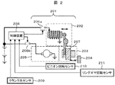
図2は本実施例におけるスタータ201と制御装置208の簡単な構造と回路接続の模式図である。スタータ201は、いわゆるピニオン押し出し方式のスタータであり、スタータモータ205とスタータモータ205によって回転駆動されるピニオンギヤ203と、ピニオンギヤ203を押し出すためのマグネットスイッチ202を備えた構成となっている。スタータモータ205の回転はその内部にある減速機構で減速することでトルクを増大させてピニオンギヤ203に伝達する。マグネットスイッチ202に通電するとピニオンギヤ203を押し出して(図2の右方向)、リングギヤ204に連結する構造となっている。ピニオンギヤ203を押し出す機能を備えるものであれば、マグネットスイッチでなくても良い。ピニオンギヤ203はワンウェイクラッチ207と一体化されている。
ピニオンギヤ203はスタータモータ205の軸方向に移動可能である。ピニオンギヤ203はエンジンのクランク軸に連結されたリングギヤ204と噛み合わせて回転することでエンジンに動力を伝えることができる。ワンウェイクラッチ207はスタータモータ205がエンジンを正回転させる方向にしか動力が伝わらない構成にする。これにより、ピニオンギヤ203、リングギヤ204に噛み合っている時は、リングギヤの回転速度は、モータ205の回転速度に対して、減速比に応じた同期速度になるか、もしくは、それよりも速い回転速度になる。すなわち、リングギヤ204がピニオンギヤ203の回転速度よりも低下しようとすると、ワンウェイクラッチ207が動力を伝達するため、リングギヤ204の回転速度がスタータモータ205に対する同期速度を下回ることはない。一方で、同期速度よりもリングギヤの回転速度の方が速い時は、ワンウェイクラッチが動力を伝達しないため、リングギヤ204からスタータモータ205側へ動力が伝達されることはない。
FIG. 2 is a schematic diagram of a simple structure and circuit connection of the
The
図2に示す通り、ピニオン回転センサ210(ピニオン回転速度検知手段)、リングギヤ回転センサ211(リングギヤ回転速度検知手段)、クランク角センサ209(クランク角検知手段)からの信号は制御装置208に入力される。なおリングギヤ204とエンジンのクランク軸は連結されているので、リングギヤ回転速度とエンジン回転速度は同義である。制御装置208は通常の燃料噴射、点火、空気制御(電子制御スロットル)に加え、ブレーキペダル状態、車速等の各種情報より、アイドルストップを許可し、燃料カットを行う。制御装置からはピニオン押し出し指令信号とモータ回転指令信号がそれぞれ独立して出力される。図2で示す通り、ピニオン押し出し指令信号を伝えるマグネットスイッチ通電用スイッチ206aとモータ回転指令信号を伝えるスタータモータ通電用スイッチ206bがピニオン押し出しとスタータモータ205の回転とを制御する。スイッチの役割を果たす部品として機械式接点を持つリレースイッチや、半導体を用いたスイッチなどを使うことができる。
As shown in FIG. 2, signals from the pinion rotation sensor 210 (pinion rotation speed detection means), the ring gear rotation sensor 211 (ring gear rotation speed detection means), and the crank angle sensor 209 (crank angle detection means) are input to the
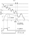
図3は本発明を含むアイドルストップシステムを実施する際の制御フローチャートであり、制御装置208の内部で実施される。また、制御フローを実施した時の、リングギヤ204とピニオンギヤ203との回転速度の時間変化と、そのときの制御装置208の出力信号の一例を図1に示す。図3に示す通り、まずアイドルストップ条件が成立したことを受けて、ステップ301にて燃料噴射を停止する。その結果、エンジン回転は惰性回転を始める。その後、図1の101で示すようにスタータモータ205に通電する。この通電による回転を予回転と称する。スタータモータ205が予回転することにより、ピニオンギヤ203が予回転する。その予回転開始の判定はステップ303で行う。予回転開始の判定方法としては、例えばエンジン回転速度が所定の回転速度を下回ったことを条件にすることが考えられる。予回転開始判定が成立した後は、ステップ304でスタータモータ304に通電して予回転を開始する。予回転は例えば一定時間、またはピニオンギヤ203の回転速度が所定の回転速度に到達すると終了する。その後は、通電をやめることでスタータモータ205が発生するトルクが失われ、ピニオンギヤ203は惰性回転に移行する。なお本実施例においては必ずしもスタータモータを予回転させる必要はなく、スタータモータが回転していない状態でも本発明を適用することはできる。予回転させることでエンジン回転速度、すなわちリングギヤ204の回転速度が比較的高い領域であってもピニオンギヤ203とリングギヤ204とのスムーズな噛み込みが可能になる。スタータモータ205の予回転後、ステップ306にてピニオン押し出し判定を行って、図1のt1のタイミングで押し出し指令を出す。この判定を行う際、判定によってピニオンギヤ203が押し出され、ピニオンギヤ203がリングギヤ204に接触する時点(すなわち、図1におけるt2)でのリングギヤ204の回転速度とピニオンギヤ203の回転速度とを予測し、それらの回転速度差が所定の値になるように、押し出しタイミングを決め、判定を行う。すなわち、図1のt1のタイミングからt2のタイミングまでがピニオン押し出し手段の遅れ時間(Tdelay)であり、この遅れ時間を考慮して、前もって押し出し指令(図1におけるt1)を出す。つまりピニオン押し出し手段の遅れ時間、すなわちピニオンが移動してリングギヤに到達するまでの時間の間のピニオンギヤ203の回転速度及びリングギヤ204の回転速度の変化を予測することで、ピニオンギヤ203がリングギヤ204に接触した時点での両者の速度差を最適な速度差になるように飛出しタイミングを決めることができ、騒音が小さくスムーズな噛み込みを実現することができる。なお、将来のリングギヤ204の回転速度の予測は時々刻々制御装置によって行われる。すなわち、時々刻々のエンジン回転速度とクランク角の情報を使って将来のリングギヤ204の回転速度を予測する。以下では時々刻々将来のリングギヤ204の回転速度を予測しようとしている時点を予測開始時点と呼ぶ。ここでのピニオン押し出し判定の実施例に関しては後に詳しく述べる。
FIG. 3 is a control flowchart for implementing the idle stop system including the present invention, and is executed inside the
ピニオンギヤ203がリングギヤ204に噛み込んだ後に発生した再始動要求に対してはステップ309にて直ちにスタータによる再始動を開始する。ピニオンギヤ203が噛み込み済みであるので、直ちにスタータモータ205に通電し、クランキングを開始することで素早い再始動を可能にする。一方、アイドルストップ開始からピニオンギヤ203が噛み込む前に、再始動要求が発生する可能性はある。それに対してはステップ302とステップ305にて判定し、ステップ310にて燃料噴射を再開し、燃焼による再始動を試みる。アイドルストップ条件が成立し、燃料カットされた後でもエンジン回転が高い領域に関しては、燃焼噴射を再開して燃焼を再開することでエンジン回転を復帰させることができるが、エンジン回転が低い領域では燃焼を再開してもそのままエンジンが止まってしまうことがある。ステップ311にてエンジンが燃焼復帰できたかどうかを判定し、燃焼復帰できなかった場合にだけステップ312にてピニオンギヤ203をリングギヤ204に噛み込ませスタータ201による再始動を行う。燃焼復帰判定は、例えばエンジン回転速度が所定の値(例えば50r/min)を下回った時点で燃焼復帰できなかったと判定することができ、またエンジン回転速度が所定の値(例えば500r/min)を上回った時点で燃焼復帰完了と見なすことができる。
In response to the restart request generated after the
次に将来のリングギヤ204の回転速度の予測方法について説明する。惰性回転中のエンジン回転速度は一定の変化率で減速していくという挙動はとらず、エンジン回転速度の変化率(回転加速度)がクランク角に対応して周期的に変化しながら回転速度を下げていくことを発明者らの研究で発見した。本実施例では、この周期的に変化しているエンジン回転速度の変化率を利用して、将来のエンジン回転速度すなわち、リングギヤ204の回転速度を予測する。まずはクランク角とエンジン回転速度の加速度の関係を近似的に関連付けるフィッティング関数をあらかじめ作成する。フィッティング関数を作成するにあたって、まず実際の惰性回転中エンジン回転速度の挙動とその時のクランク角情報を取得し、連続したエンジン回転速度からエンジン回転速度の変化率(=回転加速度)を求める。
クランク角に対応してこのエンジン回転速度の変化率は周期的に変化し、概ねクランク角によって一意に決まると仮定したうえで、クランク角をパラメータとしエンジン回転速度の変化率を近似的に求めるフィッティング関数を決める。フィッティング関数が実際のエンジン回転速度の変化率と重なるように、例えば多項式や三角関数を組み合わせてフィッティング関数を決める。図4の401に、エンジンの惰性回転中のクランク角とエンジン回転速度の加速度の関係を示したフィッティング関数の一例をグラフにしたものを示す。
なおこの例は6気筒エンジンの一例であり、クランク角は圧縮行程の気筒が上死点に達した所を0度とした。4サイクルエンジンは、クランク軸が2回転で1サイクルなので、6気筒エンジンの場合はクランク軸が120度回転するごとに別の気筒が同じ位相になる。
そのため、クランク軸が120度回転するごとにエンジンの回転速度が周期的に加減速する。よってこのフィッティング関数は0度(上死点)から始まり、120度までとなる。
4気筒エンジンの場合はクランク軸が180度回転するごとにエンジンの回転速度が周期的に加減速するのでフィッティング関数は180度までになる。惰性回転中のエンジン回転挙動について、周期的にこのフィッティング関数を参照することで、エンジン回転速度の変化率(=加速度)を得ることができる。この例ではクランク角に対し一様にエンジン回転加速度を決めた例を示してしているが、クランク角だけではなく例えばエンジン回転速度などの要素もこのフィッティング関数のパラメータに含めることができる。将来のエンジン回転速度を予測する時は、予測開始時のエンジン回転速度とクランク角を初期条件として、このエンジン回転加速度を示しているフィッティング関数を解析的または数値的に時間積分することで惰性回転中の将来の任意の時刻でのエンジン回転速度を予測することができる。例えばフィッティング関数を数値的に時間積分する際は次のように積分することができる。初期条件のクランク角情報からフィッティング関数を使って加速度を計算し微小時間をかけることで微小時間後のエンジン回転速度の変化量を得ることができ、初期条件のエンジン回転速度に加えることで微小時間後のエンジン回転速度を得ることができる。また初期条件のエンジン回転速度に微小時間をかけることで微小時間後のクランク角の変化量を求めることができ、初期条件のクランク角に加えることで微小時間後のクランク角を得ることができる。こうして微小時間後のエンジン回転速度とクランク角を連続的に計算していくことで、将来の任意の時刻でのエンジン回転速度を予測する。
Next, a method for predicting the future rotational speed of the
Fitting that approximately determines the rate of change in engine speed using the crank angle as a parameter, assuming that the rate of change in engine speed changes periodically according to the crank angle, and is determined uniquely by the crank angle. Decide on a function. The fitting function is determined by combining, for example, a polynomial or a trigonometric function so that the fitting function overlaps the actual rate of change of the engine speed. In FIG. 4, 401 shows a graph of an example of a fitting function showing the relationship between the crank angle during inertial rotation of the engine and the acceleration of the engine rotation speed.
This example is an example of a 6-cylinder engine, and the crank angle was set to 0 degree where the cylinder in the compression stroke reached the top dead center. In a 4-cycle engine, the crankshaft rotates twice and makes one cycle, so in the case of a 6-cylinder engine, every time the crankshaft rotates 120 degrees, the other cylinders have the same phase.
Therefore, every time the crankshaft rotates 120 degrees, the rotational speed of the engine is periodically accelerated and decelerated. Therefore, this fitting function starts from 0 degree (top dead center) and reaches 120 degrees.
In the case of a four-cylinder engine, every time the crankshaft rotates 180 degrees, the rotational speed of the engine is periodically accelerated and decelerated, so the fitting function is up to 180 degrees. Regarding the engine rotation behavior during inertial rotation, the rate of change (= acceleration) of the engine rotation speed can be obtained by periodically referring to this fitting function. In this example, the engine rotation acceleration is determined uniformly with respect to the crank angle. However, not only the crank angle but also factors such as the engine rotation speed can be included in the parameters of the fitting function. When predicting the future engine rotation speed, the engine rotation speed and crank angle at the start of prediction are used as initial conditions, and the fitting function indicating this engine rotation acceleration is analytically or numerically integrated over time to perform inertial rotation. The engine speed at any time in the future can be predicted. For example, when the fitting function is numerically integrated over time, it can be integrated as follows. By calculating the acceleration using the fitting function from the crank angle information of the initial condition and applying a minute time, the amount of change in the engine speed after the minute time can be obtained, and by adding to the engine speed of the initial condition, the minute time Later engine speed can be obtained. Further, it is possible to obtain the amount of change in the crank angle after a minute time by applying a minute time to the engine speed of the initial condition, and obtain the crank angle after a minute time by adding to the crank angle of the initial condition. In this way, the engine rotational speed and crank angle after a minute time are continuously calculated, so that the engine rotational speed at an arbitrary future time is predicted.
惰性回転中のエンジン回転の挙動は温度、負荷、総稼働時間などのエンジンの状態に応じて変化することがあり、また量産するにあたって個体差も発生すると考えられる。図4に示す予め作成されたフィッティング関数401だけだとエンジンの状態の変化に対し十分に対応できなく、将来のエンジン回転速度の予測が実際とずれてしまうことがある。それに対しては、エンジン回転速度の加速度を使って将来のエンジン回転速度を予測する際、予測開始時点までの過去の実際のエンジン回転速度の加速度を測定し、加速度とクランク角の対応関係を常に更新して将来のエンジン回転速度の予測に使うことができる。加速度とクランク角の対応関係を更新する際は、例えばまず、最後にエンジンを停止した時や、予測開始時点の直前までのエンジン挙動から、エンジン回転速度の変化率を計算しクランク角と対応づけて制御装置内部に記憶しておく。その際に更新された加速度とクランク角の対応関係を示すフィッティング関数の例を図4の402に示す。更新されたフィッティング関数は制御装置の電源が切れても制御装置の内部で記憶され、また温度などの情報と関連づけて更新されるようにしても良い。エンジン回転速度の変化率とクランク角の情報を制御装置内部に保持し、常に対応関係を更新して将来のエンジン回転速度の予測に使うことで、エンジン回転挙動の変化に柔軟に対応でき、より正確な予測ができるようにすることもできる。 The behavior of engine rotation during inertial rotation may change depending on engine conditions such as temperature, load, and total operating time, and individual differences are also likely to occur during mass production. If only the fitting function 401 created in advance shown in FIG. 4 is used, the change in the engine state cannot be sufficiently dealt with, and the prediction of the future engine speed may deviate from the actual. For that purpose, when predicting the future engine speed using the acceleration of the engine speed, measure the acceleration of the actual engine speed in the past until the prediction start time, and always keep the correspondence relationship between acceleration and crank angle. It can be updated and used to predict future engine speed. When updating the correspondence between acceleration and crank angle, for example, first calculate the rate of change in engine speed from the engine behavior until the last time the engine was stopped or immediately before the start of prediction, and associate it with the crank angle. And stored in the control device. An example of the fitting function indicating the correspondence relationship between the acceleration and the crank angle updated at that time is shown in 402 of FIG. The updated fitting function may be stored inside the control device even when the control device is turned off, or may be updated in association with information such as temperature. By maintaining information on the engine speed change rate and crank angle inside the control device, and constantly updating the correspondence and using it for prediction of future engine speed, it is possible to flexibly respond to changes in engine rotation behavior. It is also possible to make an accurate prediction.
エンジン回転速度の予測方法を使えば将来の任意の時刻でのエンジン回転速度を予測できる。また、惰性回転中のピニオン回転速度は一定の減速度で降下するとみなすことができるので、直線的な関係で将来のピニオン回転速度を予測することができる。よって、両者の予測を組み合わせることにより、将来の両者の回転速度差を予測することができる。
図3のステップ306では所定時間(Tdelay)経過後の予測されたリングギヤ回転速度とピニオン回転速度に基づいてピニオンの飛出し判定を行う。図5と図6に、図3のステップ306でのピニオン押し出し判定のより具体的な実施例を2つ示す。ピニオンの押し出し判定は将来のエンジン回転速度とピニオンギヤ203との回転速度差が所定の値になる時点(図1におけるt2)でピニオンギヤ203がリングギヤ204に接触するようにする。
If the engine speed prediction method is used, the engine speed at an arbitrary future time can be predicted. Further, since the pinion rotation speed during inertial rotation can be considered to drop at a constant deceleration, the future pinion rotation speed can be predicted in a linear relationship. Therefore, by combining both predictions, it is possible to predict the future rotational speed difference.
In
図5で示す方法では、ステップ501にてのエンジン回転数予測方法を用い、リングギヤ204の回転速度とピニオンギヤ203の回転速度の速度差が所定の値(ΔNref)になるまでの時間(Tp)を計算する。ステップ502にて所定の速度差になるまでの時間がピニオン押し出しの遅れ時間(Tdelay)と同じ、またはそれ以下だったら押し出し指令を出す。この方法を制御装置208で実施する際に、回転速度差が所定の値(ΔNref)になるまでの時間を、予測開始時点での回転速度差とクランク角を項目とする表で持っておき、表を参照することでその時間を計算することもできる。この表は予め将来のエンジン回転速度予測方法に基づき作成される。図5の503にて表の一例を示す。この例では予測開始時点でのリングギヤとピニオンの速度差を縦の項目とし、予測開始時点でのクランク角を横の項目としている。予測開始時点での情報を使って、ピニオンとリングギヤが接触すべき時刻(速度差がΔNrefになる時刻)までの残り時間を、表を参照することで得ることができる。ここで得られた残り時間と、ピニオン押し出しの遅れ時間(Tdelay)を比較し、残り時間がピニオンの遅れ時間と同じまたはそれ以下になった時にピニオン飛出し指令を出す。また、前記表を予め複数用意し、シフトレバーの位置、エンジンの温度や負荷などに応じて、参照する表を変えることでエンジンの状態の変化に柔軟に対応できるようにすることもできる。
In the method shown in FIG. 5, the time (Tp) until the speed difference between the rotational speed of the
図6で示す方法では、ステップ601にてのエンジン回転数予測方法を用い、Tdelay秒後のエンジン回転速度Ne′を予測し、ステップ602にてTdelay秒後のピニオン回転速度Npi′を予測する。そしてステップ603にてTdelay秒後の両者の回転速度差が所定の値(ΔNref)と同じ、または下回ったことでピニオン押し出し指令を出す。この方法を制御装置208で実施する際に将来のエンジン回転速度を、予測開始時点でのエンジン回転速度と予測開始時点でのクランク角を項目とする表で持っておき、表を参照することで将来のエンジン回転速度を計算することもできる。この表は予め将来のエンジン回転速度予測方法に基づき作成される。図6の604に表の一例を示す。この例では予測開始時点でのエンジン回転速度を縦の項目とし、予測開始時点でのクランク角を横の項目としている。予測開始時点での情報を使って、Tdelay秒後のエンジン回転速度を、この表を参照することで得ることができる。また、惰性回転中のピニオンは時間に対し一定の勾配でもって回転速度が降下すると見なすことで、Tdelay秒後のピニオン回転速度について予測することができる。Tdelay秒後の両者の速度差がΔNrefと同じ、または下回った時点でピニオン飛出し指令を出すことで、実際にTdelay秒後に両者の速度差がΔNrefの状態でピニオンギヤ203がリングギヤ204に接触し、ピニオンギヤ203とリングギヤ204との噛み込みが実現される。また、表を予め複数用意し、シフトレバーの位置、エンジンの温度や負荷などに応じて、参照する表を変えることでエンジンの状態の変化に柔軟に対応できるようにすることもできる。なお、図5に示す方法と図6に示す方法で行うピニオンギヤ203の飛出し判定は計算手順が違うだけで、原理的には同じことを判定している。
In the method shown in FIG. 6, the engine speed prediction method at Tdelay seconds is predicted using the engine speed prediction method at Step 601, and the pinion rotation speed Npi ′ after Tdelay seconds is predicted at Step 602. In
本実施例を適用すると、惰性回転中のリングギヤにピニオンを噛み込ませた後アイドルストップ中はスタータ201のピニオンギヤ203の噛み込み状態が維持され、再始動要求に備える。ピニオン203を飛出させる際は、ピニオン飛出し信号が出力された瞬間(t1)でのリングギヤ204の回転速度とピニオンギヤ203の回転速度との速度差が、その瞬間でのクランク角に対応して変化する。つまり、クランク角情報を使ってピニオンギヤ203の押し出しタイミングを判定しているので、ピニオン飛出し信号が出力された瞬間での前記速度差とクランク角を抽出すると、クランク角と前記速度差が対応した傾向を示すことが本実施例の特徴である。図7に、実際に4気筒エンジンで本発明を複数回実施した際の、ピニオン飛出し信号が出力された瞬間でのクランク角と前記速度差をグラフにしたものを示す。この例では、ピニオンがリングギヤに到達した時点(t2)でのピニオンとリングギヤの回転速度差は0〜30[r/min]の範囲に入っている。図7の例で、Aのエリアでは、クランク角が60°付近でピニオン飛出し信号が出力された瞬間でのリングギヤとピニオンの速度差は比較的小さく、Bのエリアではクランク角が140°付近になると速度差が大きいことがわかる。これは、140°付近では上死点手前でエンジン回転速度が速く減速することが予測され、両者の速度差が比較的大きくてもピニオンが接触する時には設定した速度差になると予測されピニオン飛出し判定が成立したためである。Aのエリアではエンジン回転速度は比較的遅く減速することが予測されたので、両者の速度差が小さい時に飛出し判定が成立している。このように、本発明を実施するとピニオンがリングギヤに接触した時の両者の速度差を一定範囲に収めるために、ピニオン飛出し判定が成立し飛出し信号が出力された瞬間での両者の速度差とクランク角を抽出すると、エンジン回転が大きく減速すると予測されたクランク角付近ではリングギヤとピニオンの速度差が大きくても飛出し判定が成立し、エンジン回転が比較的小さく減速するクランク角付近では両者の速度差が小さい時に飛出し判定が成立する傾向を示す。図7に示す例ではクランク角に対応してリングギヤとピニオンの速度差は単純増加で直線的な傾向を示すがエンジン挙動によっては単純増加にはならない。またこの例ではクランク角が60°付近から150°付近までの間でのみ飛出し判定が成立しているが、エンジン挙動によっては、クランク角の範囲に限定されずに飛出し判定が成立し、前記の傾向を示すことが本発明の特徴である。
When this embodiment is applied, the
ピニオンギヤ203とリングギヤ204が接触する際の騒音に関しては、両者が接触する時の速度差に応じて大きく変化することが発明者らの研究でわかっている。速度差が大きければピニオンギヤ203とリングギヤ204が同期し、ピニオンが挿入されるまでに時間を要してしまい騒音も大きくなる。一方、速度差を0に設定すればよいと云うわけではなく、わずかにリングギヤの回転速度が速い状態でピニオンと接触させる方がスムーズに噛み込みが完了し、騒音も比較的小さくなる。これは、リングギヤ回転速度の方がピニオン回転速度より速い時に接触するとワンウェイクラッチの接続が切れ、ピニオンだけがリングギヤと同期すれば噛み込めるようになるからスムーズに噛み込めるが、逆の場合はワンウェイクラッチが接続しモータを同期させるための衝撃が大きくなるからである。本実施例ではピニオンとリングギヤが接触する際の速度差を任意の速度差に設定できるので、騒音が小さい速度差に設定することで速度差に依存する騒音を抑えることができる。
It has been found by the inventors' research that the noise when the
101 予回転でのモータ通電信号
201 スタータ
202 マグネットスイッチ
203 ピニオンギヤ
204 リングギヤ
205 スタータモータ
206a マグネットスイッチ通電用スイッチ
206b スタータモータ通電用スイッチ
207 ワンウェイクラッチ
208 制御装置
209 クランク角センサ
210 ピニオン回転センサ
211 リングギヤ回転センサ
401 エンジン回転速度の加速度とクランク角の関係を示すフィッティング関数の例
402 エンジン状態が変化した時のフィッティング関数の例
ΔNref ピニオンとリングギヤが接触する時の目標とする速度差
Tdelay ピニオン飛出し信号から実際にピニオンがリングギヤに接触するまでの遅れ時間
Tp 現時点から、速度差がΔNrefになる時点までの残り時間
Ne′ Tdelay秒後のエンジン回転速度
Npi′ Tdelay秒後のピニオン回転速度
t1 ピニオン押し出しタイミング
t2 ピニオンがリングギヤに接触するタイミング
101 Pre-rotation
Claims (6)
前記アイドルストップシステムは、
前記リングギヤの回転速度を検知するリングギヤ回転速度検知手段と、
前記エンジンのクランク軸のクランク角を検知するクランク角検知手段と、
前記ピニオンの回転速度を検知するピニオン回転速度検知手段と、
を備え、
前記制御装置は、前記ピニオンを回転駆動させた後に回転駆動を停止して前記ピニオンが惰性回転しているときの前記ピニオンの将来の回転速度の減速を前記ピニオン回転速度検知手段に基づいて予測するピニオン回転速度予測手段を備え、
前記リングギヤ回転速度検知手段と前記クランク角検知手段に基づいて
将来のエンジン回転速度を予測し、さらに前記ピニオン回転速度検知手段に基づきピニオン回転速度をピニオンのリングギヤとの減速比を考慮して換算したピニオン回転速度と、リングギヤの回転速度が所定の速度差で接触するよう、ピニオンの押し出し手段の遅れを考慮してピニオン押し出し手段の押し出しタイミングを制御することを特徴とする、アイドルストップシステムを制御する制御装置。 Fuel injection is stopped when the idle stop condition is satisfied during engine operation, and the pinion gear is engaged with the ring gear connected to the crankshaft of the engine during the engine inertia period until the engine speed reaches zero In the control device of the idle stop system of the system,
The idle stop system is
A ring gear rotation speed detection means for detecting the rotation speed of the ring gear;
Crank angle detecting means for detecting the crank angle of the crankshaft of the engine;
Pinion rotation speed detection means for detecting the rotation speed of the pinion;
With
The control device predicts a reduction in the future rotational speed of the pinion based on the pinion rotational speed detection means when the pinion rotates in inertia after the pinion is rotationally driven and the pinion is inertially rotated. Equipped with a pinion rotation speed prediction means,
A future engine rotation speed is predicted based on the ring gear rotation speed detection means and the crank angle detection means, and the pinion rotation speed is converted in consideration of a reduction ratio with the pinion ring gear based on the pinion rotation speed detection means. The idle stop system is controlled by controlling the pushing timing of the pinion pushing means in consideration of the delay of the pushing means of the pinion so that the rotation speed of the pinion and the rotating speed of the ring gear come into contact with each other with a predetermined speed difference. Control device.
エンジン惰性回転期間中のクランク角に対応づけ
られるエンジン回転速度の加速度に、予測開始時点以前の段階でクランク角に対応するエンジン回転速度の加速度を測定し、将来のエンジン回転速度の予測に適用することを特徴とするアイドルストップシステムを制御する制御装置。 3. The control device according to claim 2, wherein the control device uses the ring gear rotation speed detection means and the crank angle detection means to measure a correspondence relationship between the engine rotation acceleration and the crank angle and stores it in the control device. It has a correspondence update function,
The acceleration of the engine rotation speed corresponding to the crank angle is measured before the prediction start time to the acceleration of the engine rotation speed associated with the crank angle during the engine inertia rotation period, and applied to the prediction of the future engine rotation speed. A control device for controlling an idle stop system.
Priority Applications (4)
| Application Number | Priority Date | Filing Date | Title |
|---|---|---|---|
| JP2010174989A JP5450311B2 (en) | 2010-08-04 | 2010-08-04 | Idle stop control method and control apparatus |
| EP11175747A EP2416002A1 (en) | 2010-08-04 | 2011-07-28 | Idle stop control method and control device |
| CN201110213559.9A CN102374092B (en) | 2010-08-04 | 2011-07-28 | Idle stop control method and control device |
| US13/196,099 US8688359B2 (en) | 2010-08-04 | 2011-08-02 | Idle stop control method and control device |
Applications Claiming Priority (1)
| Application Number | Priority Date | Filing Date | Title |
|---|---|---|---|
| JP2010174989A JP5450311B2 (en) | 2010-08-04 | 2010-08-04 | Idle stop control method and control apparatus |
Publications (3)
| Publication Number | Publication Date |
|---|---|
| JP2012036747A JP2012036747A (en) | 2012-02-23 |
| JP2012036747A5 JP2012036747A5 (en) | 2012-10-18 |
| JP5450311B2 true JP5450311B2 (en) | 2014-03-26 |
Family
ID=44651063
Family Applications (1)
| Application Number | Title | Priority Date | Filing Date |
|---|---|---|---|
| JP2010174989A Active JP5450311B2 (en) | 2010-08-04 | 2010-08-04 | Idle stop control method and control apparatus |
Country Status (4)
| Country | Link |
|---|---|
| US (1) | US8688359B2 (en) |
| EP (1) | EP2416002A1 (en) |
| JP (1) | JP5450311B2 (en) |
| CN (1) | CN102374092B (en) |
Families Citing this family (19)
| Publication number | Priority date | Publication date | Assignee | Title |
|---|---|---|---|---|
| JP5094889B2 (en) * | 2010-01-14 | 2012-12-12 | 日立オートモティブシステムズ株式会社 | Fuel consumption-saving vehicle control system |
| US8408175B2 (en) * | 2010-08-03 | 2013-04-02 | GM Global Technology Operations LLC | Stop-start self-synchronizing starter system |
| JP5450311B2 (en) * | 2010-08-04 | 2014-03-26 | 日立オートモティブシステムズ株式会社 | Idle stop control method and control apparatus |
| JP5240262B2 (en) * | 2010-09-14 | 2013-07-17 | 株式会社デンソー | Engine automatic stop / start control device |
| JP2013007307A (en) * | 2011-06-23 | 2013-01-10 | Isuzu Motors Ltd | Control method of idling stop of internal combustion engine, and idling stop system |
| DE102011090158A1 (en) * | 2011-12-30 | 2013-07-04 | Robert Bosch Gmbh | Method for engaging a starting pinion of a starting device in a ring gear of an internal combustion engine |
| JP5962463B2 (en) * | 2012-11-27 | 2016-08-03 | 三菱自動車工業株式会社 | Engine start determination device |
| US20140260793A1 (en) * | 2013-03-15 | 2014-09-18 | Remy Technologies, L.L.C. | Starter motor for a motor vehicle |
| JP6181954B2 (en) * | 2013-03-25 | 2017-08-16 | 日立オートモティブシステムズ株式会社 | Vehicle control device |
| JP6101530B2 (en) | 2013-03-26 | 2017-03-22 | 日立オートモティブシステムズ株式会社 | In-vehicle control device and starter |
| JP6089899B2 (en) * | 2013-04-09 | 2017-03-08 | 株式会社デンソー | Engine automatic stop / start control device |
| JP6062324B2 (en) * | 2013-06-14 | 2017-01-18 | 日立オートモティブシステムズ株式会社 | Engine starter and engine start control method |
| GB2517428A (en) * | 2013-08-19 | 2015-02-25 | Gm Global Tech Operations Inc | Method of controlling a tandem solenoid starter |
| US9989031B2 (en) | 2013-09-10 | 2018-06-05 | Mitsubishi Electric Corporation | Engine automatic stop/restart device |
| JP6093682B2 (en) * | 2013-10-11 | 2017-03-08 | 日立オートモティブシステムズ株式会社 | Vehicle control device |
| JP2015081537A (en) * | 2013-10-22 | 2015-04-27 | ダイハツ工業株式会社 | Start control device of internal combustion engine |
| TWI605191B (en) | 2014-11-11 | 2017-11-11 | 財團法人工業技術研究院 | Crankshaft angle control method and system thereof |
| JP6035616B2 (en) * | 2015-07-03 | 2016-11-30 | 日立オートモティブシステムズ株式会社 | Idle stop control device for internal combustion engine |
| JP6504006B2 (en) * | 2015-09-29 | 2019-04-24 | 株式会社デンソー | Engine control device |
Family Cites Families (21)
| Publication number | Priority date | Publication date | Assignee | Title |
|---|---|---|---|---|
| JP4214401B2 (en) | 2004-05-18 | 2009-01-28 | 株式会社デンソー | Engine automatic stop / restart device |
| JP2006194125A (en) * | 2005-01-12 | 2006-07-27 | Toyota Motor Corp | Misfire determining device and misfire determining method for internal combustion engine |
| JP4525538B2 (en) * | 2005-02-24 | 2010-08-18 | トヨタ自動車株式会社 | Misfire determination device and misfire determination method for internal combustion engine |
| DE102005049092B4 (en) * | 2005-10-13 | 2016-06-02 | Robert Bosch Gmbh | A method for meshing the starter pinion of a starter in the starter tooth circuit of an internal combustion engine when the internal combustion engine |
| DE102006011644A1 (en) * | 2006-03-06 | 2007-09-13 | Robert Bosch Gmbh | Device having a first gear part for meshing in a second gear part, in particular starting device with a pinion for meshing in a ring gear of an internal combustion engine and method for operating such a device |
| JP2008215182A (en) * | 2007-03-05 | 2008-09-18 | Denso Corp | Engine revolution stop control device |
| JP4666286B2 (en) * | 2007-03-05 | 2011-04-06 | 株式会社デンソー | Engine rotation stop control device |
| FR2925616A1 (en) * | 2007-12-20 | 2009-06-26 | Renault Sas | CONTROL METHOD FOR STARTER OF A COMBUSTION ENGINE AND ITS APPLICATION |
| JP5251751B2 (en) * | 2008-07-04 | 2013-07-31 | トヨタ自動車株式会社 | Starter for internal combustion engine |
| DE102008041037A1 (en) * | 2008-08-06 | 2010-02-11 | Robert Bosch Gmbh | Method and device of a control for a start-stop operation of an internal combustion engine |
| DE102008042946A1 (en) * | 2008-10-20 | 2010-04-29 | Robert Bosch Gmbh | Method and apparatus of a start-stop control for an internal combustion engine |
| JP2010127229A (en) * | 2008-11-28 | 2010-06-10 | Mitsubishi Electric Corp | Control device of internal combustion engine |
| EP2211051B8 (en) * | 2009-01-21 | 2019-09-11 | Denso Corporation | System for restarting internal combustion engine |
| JP2010229882A (en) | 2009-03-27 | 2010-10-14 | Hitachi Automotive Systems Ltd | Vehicle control device and idling stop system |
| DE102010061084A1 (en) * | 2009-12-08 | 2011-07-21 | DENSO CORPORATION, Aichi-pref. | System for cranking an internal combustion engine by engaging a pinion with a ring gear |
| DE102010001257A1 (en) * | 2010-01-27 | 2011-07-28 | Robert Bosch GmbH, 70469 | Method and control device for determining a future speed |
| JP5565279B2 (en) * | 2010-02-01 | 2014-08-06 | 株式会社デンソー | Engine start control device |
| JP5321524B2 (en) * | 2010-04-07 | 2013-10-23 | 株式会社デンソー | Engine automatic stop / start control device |
| JP5073007B2 (en) * | 2010-04-28 | 2012-11-14 | 三菱電機株式会社 | Engine automatic stop / restart device |
| JP5450311B2 (en) * | 2010-08-04 | 2014-03-26 | 日立オートモティブシステムズ株式会社 | Idle stop control method and control apparatus |
| JP5276697B2 (en) * | 2011-06-15 | 2013-08-28 | 三菱電機株式会社 | On-board engine start control device |
-
2010
- 2010-08-04 JP JP2010174989A patent/JP5450311B2/en active Active
-
2011
- 2011-07-28 CN CN201110213559.9A patent/CN102374092B/en active Active
- 2011-07-28 EP EP11175747A patent/EP2416002A1/en not_active Withdrawn
- 2011-08-02 US US13/196,099 patent/US8688359B2/en active Active
Also Published As
| Publication number | Publication date |
|---|---|
| JP2012036747A (en) | 2012-02-23 |
| US8688359B2 (en) | 2014-04-01 |
| CN102374092B (en) | 2014-10-29 |
| EP2416002A1 (en) | 2012-02-08 |
| US20120035827A1 (en) | 2012-02-09 |
| CN102374092A (en) | 2012-03-14 |
Similar Documents
| Publication | Publication Date | Title |
|---|---|---|
| JP5450311B2 (en) | Idle stop control method and control apparatus | |
| JP6101530B2 (en) | In-vehicle control device and starter | |
| US8793061B2 (en) | Control device for controlling automatic engine stop and start | |
| JP4214401B2 (en) | Engine automatic stop / restart device | |
| JP5464095B2 (en) | Engine stop / start control device | |
| US9267479B2 (en) | Engine starting device and engine starting method | |
| JP5321524B2 (en) | Engine automatic stop / start control device | |
| JP5428931B2 (en) | Starter control device | |
| JP5094889B2 (en) | Fuel consumption-saving vehicle control system | |
| JP4735737B2 (en) | Engine stop / start control device | |
| JP2011140938A (en) | Engine automatic stop-and-start control apparatus | |
| JP2011174459A (en) | Engine start control device | |
| JP2016205174A (en) | Engine control device | |
| JP2011140939A (en) | Engine automatic stop-and-start control appartus | |
| JP5477239B2 (en) | Engine stop / start control device | |
| JP5548102B2 (en) | Vehicle control device | |
| JP6181954B2 (en) | Vehicle control device | |
| JP5240262B2 (en) | Engine automatic stop / start control device | |
| JP6357308B2 (en) | In-vehicle control device | |
| JP5822754B2 (en) | Engine control system for idle stop | |
| JP2013142289A (en) | Idling stop control device | |
| JP2011157948A (en) | Fuel injection control device | |
| JP5370173B2 (en) | Engine automatic stop / start control device | |
| JP2015140688A (en) | Idling stop system control device | |
| JP2011157947A (en) | Idle stop control device |
Legal Events
| Date | Code | Title | Description |
|---|---|---|---|
| RD04 | Notification of resignation of power of attorney |
Free format text: JAPANESE INTERMEDIATE CODE: A7424 Effective date: 20120518 |
|
| A521 | Request for written amendment filed |
Free format text: JAPANESE INTERMEDIATE CODE: A523 Effective date: 20120829 |
|
| A621 | Written request for application examination |
Free format text: JAPANESE INTERMEDIATE CODE: A621 Effective date: 20120829 |
|
| A521 | Request for written amendment filed |
Free format text: JAPANESE INTERMEDIATE CODE: A523 Effective date: 20120829 |
|
| A977 | Report on retrieval |
Free format text: JAPANESE INTERMEDIATE CODE: A971007 Effective date: 20130711 |
|
| A131 | Notification of reasons for refusal |
Free format text: JAPANESE INTERMEDIATE CODE: A131 Effective date: 20130717 |
|
| A521 | Request for written amendment filed |
Free format text: JAPANESE INTERMEDIATE CODE: A523 Effective date: 20130917 |
|
| TRDD | Decision of grant or rejection written | ||
| A01 | Written decision to grant a patent or to grant a registration (utility model) |
Free format text: JAPANESE INTERMEDIATE CODE: A01 Effective date: 20131126 |
|
| A61 | First payment of annual fees (during grant procedure) |
Free format text: JAPANESE INTERMEDIATE CODE: A61 Effective date: 20131225 |
|
| R150 | Certificate of patent or registration of utility model |
Ref document number: 5450311 Country of ref document: JP Free format text: JAPANESE INTERMEDIATE CODE: R150 Free format text: JAPANESE INTERMEDIATE CODE: R150 |
|
| S533 | Written request for registration of change of name |
Free format text: JAPANESE INTERMEDIATE CODE: R313533 |
|
| R350 | Written notification of registration of transfer |
Free format text: JAPANESE INTERMEDIATE CODE: R350 |
|
| R250 | Receipt of annual fees |
Free format text: JAPANESE INTERMEDIATE CODE: R250 |