JP2015140688A - Idling stop system control device - Google Patents
Idling stop system control device Download PDFInfo
- Publication number
- JP2015140688A JP2015140688A JP2014012653A JP2014012653A JP2015140688A JP 2015140688 A JP2015140688 A JP 2015140688A JP 2014012653 A JP2014012653 A JP 2014012653A JP 2014012653 A JP2014012653 A JP 2014012653A JP 2015140688 A JP2015140688 A JP 2015140688A
- Authority
- JP
- Japan
- Prior art keywords
- engine
- fuel
- restart
- rotation
- starter motor
- Prior art date
- Legal status (The legal status is an assumption and is not a legal conclusion. Google has not performed a legal analysis and makes no representation as to the accuracy of the status listed.)
- Ceased
Links
Images


Classifications
-
- Y—GENERAL TAGGING OF NEW TECHNOLOGICAL DEVELOPMENTS; GENERAL TAGGING OF CROSS-SECTIONAL TECHNOLOGIES SPANNING OVER SEVERAL SECTIONS OF THE IPC; TECHNICAL SUBJECTS COVERED BY FORMER USPC CROSS-REFERENCE ART COLLECTIONS [XRACs] AND DIGESTS
- Y02—TECHNOLOGIES OR APPLICATIONS FOR MITIGATION OR ADAPTATION AGAINST CLIMATE CHANGE
- Y02T—CLIMATE CHANGE MITIGATION TECHNOLOGIES RELATED TO TRANSPORTATION
- Y02T10/00—Road transport of goods or passengers
- Y02T10/10—Internal combustion engine [ICE] based vehicles
- Y02T10/40—Engine management systems
Abstract
Description
本発明は、エンジンの停止と再始動を自動的に行うアイドルストップシステムの制御装置に関する。 The present invention relates to a control device for an idle stop system that automatically stops and restarts an engine.
近年、エネルギ資源の節約と環境保全を目的とした自動車の技術が開発されている。例えば、運転中に所定の条件(自動停止条件)が成立した時に、エンジンに供給する燃料を停止し、エンジンが発生するトルクを失わせるアイドルストップシステムを搭載したものがある。エンジン自動停止条件は、運転者がアクセルから足を離したり、ブレーキを踏んだりすることで成立する。 In recent years, automobile technologies aimed at saving energy resources and protecting the environment have been developed. For example, there is a vehicle equipped with an idle stop system that stops fuel supplied to an engine and loses torque generated by the engine when a predetermined condition (automatic stop condition) is satisfied during operation. The engine automatic stop condition is satisfied when the driver removes his or her foot from the accelerator or steps on the brake.
このアイドルストップシステムでは、車両が停止していなくても、エンジン自動停止条件が成立したらエンジンを自動的に停止する。その後、エンジンのクランク軸が回転停止するまでのエンジン惰性回転期間中に、エンジンを再始動する要求(再始動要求)が発生したとき、できるだけ速やかにエンジンを再始動することが求められる。再始動要求とは、例えば運転手がブレーキペダルから足を離す等である。 In this idle stop system, even if the vehicle is not stopped, the engine is automatically stopped when the engine automatic stop condition is satisfied. Thereafter, when a request for restarting the engine (restart request) occurs during the engine inertia rotation period until the crankshaft of the engine stops rotating, it is required to restart the engine as soon as possible. The restart request is, for example, that the driver removes his foot from the brake pedal.
この要求を満たす技術として、例えば、アイドルストップ要求発生直後のエンジン惰性回転期間中に再始動要求が発生した時、停止した燃料をエンジンへ再度供給することで、エンジンの燃焼を再開させる燃焼復帰再始動を行なう技術が挙げられる。ここで、エンジンの状態によっては燃焼が良好に行われず、燃焼復帰再始動が困難な場合には、燃料を再度供給した最初の気筒が膨張行程以降のときのリングギアの回転数に基づきスタータによる始動アシストとして、スタータを駆動することによるスタータアシスト再始動を行なっている(たとえば特許文献1参照)。 As a technique for satisfying this requirement, for example, when a restart request is generated during an engine inertia rotation period immediately after an idle stop request is generated, the fuel that has been stopped is supplied again to the engine, so that the combustion recovery is resumed. A technique for starting is mentioned. Here, depending on the state of the engine, if the combustion is not performed well and it is difficult to restart the combustion, it is determined by the starter based on the rotation speed of the ring gear when the first cylinder to which fuel is supplied again is after the expansion stroke. As start assist, starter assist restart is performed by driving the starter (see, for example, Patent Document 1).
上述の背景により、アイドルストップシステムにおいては、アイドルストップ要求発生直後のエンジン惰性回転期間中に再始動要求が発生した時、できるだけ速やかにエンジンを再始動することが要求される。しかし、上記従来のアイドルストップシステムでは、アイドルストップ要求発生直後のエンジン惰性回転期間中に、スタータアシストをするタイミングは、燃料を再度供給した最初の気筒が膨張行程以降のときであるため、エンジンの再始動時間が長くなるおそれがあった。本発明は、このような点を鑑みてなされたものであり、その目的とするところは、アイドルストップ後にエンジンの再始動要求が発生した場合に、速やかにエンジンの再始動を行うことができるアイドルストップシステムの制御装置を提供することにある。 Due to the above background, in an idle stop system, when a restart request is generated during an engine inertia rotation period immediately after the occurrence of an idle stop request, it is required to restart the engine as soon as possible. However, in the conventional idle stop system described above, the starter assist is performed during the engine inertia rotation period immediately after the occurrence of the idle stop request, because the first cylinder to which fuel is supplied again is after the expansion stroke. There was a risk of a long restart time. The present invention has been made in view of such a point, and an object of the present invention is to provide an idle engine that can promptly restart the engine when an engine restart request is generated after the idle stop. It is to provide a control device for a stop system.
前記課題を解決すべく、本発明に係るアイドルストップシステムの制御装置は、燃料供給停止後、エンジン惰性回転中に、エンジンの再始動要求がされた際に、エンジンに燃料を供給し、燃料が最初に供給された気筒が燃料供給後の膨張行程に達するまでの間に、クランク軸と同期したリングギアの回転数とスタータのピニオンギアの回転数との回転数差に基づき、スタータモータによるエンジンの再始動のアシストを行うか否かを判定し、スタータモータによる再始動アシストを行うと判定したときに、リングギアをピニオンギアに噛み込ませ、スタータモータを駆動することによりエンジンの再始動をアシストする。 In order to solve the above problems, the control device for the idle stop system according to the present invention supplies fuel to the engine when the engine is requested to restart during engine inertia after the fuel supply is stopped. The engine with the starter motor is based on the difference between the rotation speed of the ring gear synchronized with the crankshaft and the rotation speed of the starter pinion gear until the first supplied cylinder reaches the expansion stroke after fuel supply. When it is determined whether or not to perform the restart assist, and when it is determined to perform the restart assist by the starter motor, the ring gear is engaged with the pinion gear and the starter motor is driven to restart the engine. Assist.
本発明によれば、アイドルストップ後にエンジンの再始動要求が発生した場合に、速やかにエンジンの再始動を行うことができる。 According to the present invention, when an engine restart request is generated after an idle stop, the engine can be restarted promptly.
本発明を以下の2つの実施形態により説明する。
〔第1実施形態〕
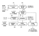
図1は、本発明の第1実施形態に係るアイドルストップシステム1の装置構成および回路接続状態を示した模式図である。本実施形態では、アイドルストップシステム1は、燃料を供給することによりクランク軸が回転するエンジン(図示せず)と、エンジンの始動をアシストするスタータ101と、スタータ101およびエンジンを制御する制御装置108とを備えている。
The present invention is illustrated by the following two embodiments.
[First Embodiment]
FIG. 1 is a schematic diagram showing a device configuration and a circuit connection state of an
本実施形態に係るスタータ101は、いわゆるピニオンギア押し出し方式のスタータであり、具体的には、エンジンの始動をアシストするスタータモータ105と、スタータモータ105により回転駆動するピニオンギア103と、ピニオンギア103を押し出すためのマグネットスイッチ102と、を少なくとも備えている。
A
スタータモータ105の回転はその内部にある減速機構で減速する。これによりスタータモータ105のトルクを増大させてピニオンギア103に伝達される。スタータモータ105は、マグネットスイッチ102に通電するとピニオンギア103を押し出して(図1の右方向)、リングギア104に噛み込ませる構造となっている。ここで、リングギア104は、エンジンのクランク軸の回転に同期するものであり、クランク軸に取付けられている。なお、ピニオンギア103を押し出す機能を備えるものであれば、本実施形態の如きマグネットスイッチに限定されるものではない。
The rotation of the
ピニオンギア103はワンウェイクラッチ107と一体化されている。上述した如く、ピニオンギア103は、制御装置108からのマグネットスイッチ102への通電により、スタータモータ105の軸方向に移動可能な構造となっている。ピニオンギア103はエンジンのクランク軸に連結されたリングギア104と噛み合わせて回転することでエンジンに動力を伝えることができる。
The
ワンウェイクラッチ107はスタータモータ105がエンジンを正回転させる方向にしか動力が伝わらない構成にする。これにより、ピニオンギア103がリングギア104に噛み合っている時は、リングギア104の回転数は、スタータモータ105の回転数に対して、減速比に応じた同期回転数になるか、もしくは、それよりも速い回転数になる。
The one-
すなわち、リングギア104がピニオンギア103の回転速数よりも低下しようとすると、ワンウェイクラッチ107が動力を伝達するため、リングギア104の回転数がスタータモータ105に対する同期回転数を下回ることはない。一方で、同期回転数よりもリングギアの回転数の方が高い時は、ワンウェイクラッチが動力を伝達しないため、リングギア104からスタータモータ105側へ動力が伝達されることはない。
That is, if the
図1に示すように、アイドルストップシステム1は、燃料を供給することによりクランク軸が回転するエンジンと、クランク軸の回転に同期したリングギア104と、エンジンの始動をアシストするスタータモータ105と、エンジンの始動をアシストする際にリングギア104に噛み込むとともにスタータモータ105により回転駆動するピニオンギア103とを少なくとも備えている。
As shown in FIG. 1, the
図1に示す通り、クランク角度センサ109(エンジン回転数検出装置、クランク角度検出装置)からの信号、ピニオン回転センサ110(ピニオン回転数検出装置)、ブレーキスイッチ111、車速センサ112からの信号は制御装置108に入力される。なお、リングギア104とエンジンのクランク軸は連結されているので、リングギア回転数とクランク軸回転数(エンジン回転数)は同義である。
As shown in FIG. 1, signals from the crank angle sensor 109 (engine speed detector, crank angle detector), signals from the pinion speed sensor 110 (pinion speed detector), the
制御装置108は、通常の燃料噴射制御(燃料噴射弁の制御)、点火(点火プラグの制御)、空気制御(電子制御スロットルの制御)を行っている。これに加えて、制御装置108は、ブレーキスイッチからの信号に基づくブレーキペダル状態、車速センサ112からの車速等の各種情報(車両の運転状態)から、アイドルストップ条件の成立を判定する。ここで、アイドルストップ条件が成立した場合には、エンジンのアイドルストップを許可し、燃料噴射弁を制御することによりエンジンへの燃料の供給を停止し、これによりエンジンを自動停止させる(アイドルストップさせる)。
The
上述した車両の運転状態から、エンジンの再始動要求が発生した時には、制御装置は、燃料噴射弁を制御することによりエンジンへの燃料供給の再開をするとともに、点火プラグを制御することにより点火タイミングを制御する。このようにしてエンジン再始動制御が実行される。 When an engine restart request is generated from the vehicle operating state described above, the control device restarts the fuel supply to the engine by controlling the fuel injection valve, and controls the spark plug to control the ignition timing. To control. In this way, engine restart control is executed.
また、制御装置108からはピニオン押し出し指令信号とモータ回転指令信号がそれぞれ独立して出力される。図1で示す通り、ピニオン押し出し指令信号を伝えるマグネットスイッチ通電用スイッチ106aとモータ回転指令信号を伝えるスタータモータ通電用スイッチ106bが、ピニオンギア103の押し出しとスタータモータ105の回転とを制御する。マグネットスイッチ通電用スイッチ106aおよびスタータモータ通電用スイッチ106bとして、例えば機械式接点を持つリレースイッチや、半導体を用いたスイッチなどを使うことができる。
The
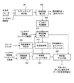
このような装置構成からなるアイドルストップシステム1において、制御装置108は、以下の如き制御を行う。図2は、本発明の第1実施形態に係るアイドルストップシステムを制御する制御装置の制御ブロック図である。
In the
図1に示す制御装置108は、上述した車両の運転状態を検出するセンサの出力信号をA/D変換器を介して入力し、入力したデータおよび予めメモリー等で記憶されたデータに基づいて以下に示す演算等をCPUで行い、A/D変換器を介して制御信号を出力することによりアイドルストップシステム1を制御する。
The
ソフトウエアの構成として、制御装置108は、少なくとも図2に示すよう制御ブロックで構成される。具体的には、アイドルストップ判定部201は、車速センサからの車速信号、ブレーキスイッチ信号、リングギア回転数等により車両がアイドルストップの条件が成立しているかを判定する。燃料供給停止部202は、アイドルストップ判定部201でアイドルストップの条件が成立したときにエンジンへの燃料供給の停止を行う。具体的には、エンジン内で燃料の燃焼が行われないように、燃料噴射弁の制御を行う。この際、必要に応じて点火プラグによる点火を停止するように、点火プラグの制御も行ってよい。
As a software configuration, the
ここで、燃料供給停止部202でエンジンへの燃料供給が停止した際には、エンジン回転数が低下する。そこで、惰性回転判定部203では、前記エンジンの再始動要求がされた際に、エンジンが惰性回転しているかどうかを判定する。具体的には、燃料供給停止部202により燃料供給が停止してからクランク軸(エンジン)の回転が停止するまでの間のエンジン惰性回転中であるか否かを判定する。より具体的なエンジン惰性回転中であるか否かの判定は、リングギア回転数(エンジン回転数)またはその変化量(クランク角度の変化度合い)に基づいて行う。
Here, when the fuel supply to the engine is stopped by the fuel
ここで、エンジンの再始動要求がされたか否かの判定は、再始動要求判定部204で、ブレーキスイッチの信号等に基づいて行われる。たとえば、ブレーキスイッチがオフの場合、エンジンの再始動要求がされたと判定される。燃焼復帰部205は、上述した燃焼復帰の条件が成立したときに、燃料噴射量の制御、点火タイミングの制御、および吸入空気量の制御を行うべく、燃料噴射弁、燃料点火プラグ、およびスロットル弁に制御信号を出力する。燃焼復帰部205は、惰性回転判定部203がエンジン惰性回転中であると判定したときに、エンジンに燃料を供給し、供給した燃料を燃焼する。
Here, whether or not an engine restart request has been made is determined by the restart
再始動アシスト判定部207は、燃焼復帰部205により燃料が最初に供給された気筒が燃料供給後の膨張行程に達する(具体的には膨張行程に達しエンジン回転数が上昇する)までの間に、リングギアの回転数とピニオンギアの回転数との回転数差に基づき、スタータ101によるエンジンの再始動のアシストを行うか否かを判定する。ここで、リングギアの回転数とピニオンギアの回転数との回転数差は、回転数差演算部206で演算され、この回転数差が所定値以下になったときに、再始動アシスト判定部207は、スタータ101による再始動アシストの許可信号を出力する。
The restart assist
再始動アシスト部208は、再始動アシストの許可信号が出力されたタイミングで、リングギア104をピニオンギア103に噛み込ませ、スタータモータ105を駆動することによりエンジンの再始動をアシストする。具体的には、再始動アシスト部208はピニオン押し出し指令信号とモータ回転指令信号とを出力し、マグネットスイッチ通電用スイッチ106aとスタータモータ通電用スイッチ106bを制御する。これにより、エンジンの再始動のアシストが実行される。
The
なお、惰性回転判定部203で、エンジン惰性回転中でないと判断した場合であっても、再始動要求判定部204で再始動要求の条件が成立した場合には、通常の再始動アシストを行う。この際には、再始動アシスト判定部207で再始動アシストの判定を行わず再始動アシスト部208でスタータによるエンジン再始動のアシストを行いつつ、燃焼復帰部205による燃焼復帰を行う。
Even when the inertial
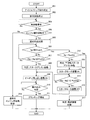
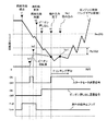
図3は、図2に示す制御装置のフローチャートであり、図4は、図2に示すアイドルストップシステムのタイミングチャートを示した図である。図3に示すように、まずステップ301において、アイドルストップ判定部201がアイドルストップ条件の成立を判定した場合ステップ302に進む。ステップ302において、アイドルストップ条件の成立に応じて燃料供給停止部202が燃料供給を停止しステップ303に進む。このとき、図4に示すように、時刻t1で燃料供給停止フラグはLowからHighとなる。その結果、エンジン回転は惰性回転を始める。
3 is a flowchart of the control device shown in FIG. 2, and FIG. 4 is a diagram showing a timing chart of the idle stop system shown in FIG. As shown in FIG. 3, when the idle
次にステップ303では、再始動要求判定部204は再始動要求が発生したかを判定する。ステップ303で再始動要求が発生したと判定された場合には(図4における時刻t2)、ステップ304に進み、惰性回転判定部203はエンジン惰性回転中であるか否かを判定する。エンジン惰性回転中であるか否かの判定は、例えば、エンジン回転数から判定してもよいし、クランク角度の変化度合いから判定してもよい。
In
ここで、再始動要求判定部204で再始動要求がされていると判定し、ステップ304において惰性回転判定部203がエンジン惰性回転中でないと判定した場合、エンジン回転数とピニオンギアの回転数はどちらも0r/minであり、同期しているため、ステップ318に進み、通常の再始動制御を行う。
Here, when it is determined that the restart request is determined by the restart
通常の再始動制御では、上述したように、再始動アシスト部208からの押出し指令信号により、マグネットスイッチ102に通電してピニオンギア103を押し出してリングギア104に噛み合わせる。次に、再始動アシスト部208からのモータ回転指令信号により、スタータモータ105に通電する。これによりエンジンをクランキングして、燃焼復帰部205により燃料供給を再開し(燃焼復帰をし)、エンジンを再始動させる。
In normal restart control, as described above, the
一方、ステップ304においてエンジン惰性回転中と判定した場合には、ステップ305に進み、燃焼復帰部205で燃料供給を再開し、ステップ306に進む。ステップ306では、エンジン回転数Ne1の読み込みタイミングに達しているか判定する。
On the other hand, if it is determined in
具体的には、エンジン回転数Ne1の読み込みタイミングは、燃料供給を最初に再開した気筒のクランク角度が、膨張行程以降のタイミングを想定している。すなわち、ステップ305で燃料供給を再開し、燃焼による再始動の実行を要求しても、直ちにエンジンの回転速度が上昇する訳でなく、一定期間の経過を待たなければならない。これは、吸気ポートに燃料を噴射するPFIエンジンを例にすると、燃料供給の再開から、最初に燃料噴射を行った気筒において、燃料噴射を行う吸気行程から燃焼トルクを得ることができる膨張行程まで時間を要するためである。
Specifically, the reading timing of the engine speed Ne1 is assumed to be the timing after the expansion stroke of the crank angle of the cylinder in which fuel supply is first resumed. That is, even if the fuel supply is resumed in
これまでは、燃料が最初に供給された気筒において、点火プラグにより燃料が燃焼後である膨張行程以降において、エンジン回転数Ne1が読み込まれることから、この読み込みタイミングを利用して、スタータによるアシストを行うか否かを判定していたが、この場合には、スタータによる再始動のタイミングが遅れてしまう。そこで、本実施形態では、燃焼復帰部205により燃料が最初に供給された気筒が燃料供給後の膨張行程に達するまでの間に(具体的には、ステップ306においてNo、すなわちエンジン回転数の読み込みがされていないときに)、スタータによるエンジンの再始動のアシストを行うか否かを判定し、これを実行する。
Until now, in the cylinder to which fuel is first supplied, the engine speed Ne1 is read after the expansion stroke after the fuel is burned by the spark plug. Therefore, the starter assists using the read timing. In this case, the restarting timing by the starter is delayed. Therefore, in the present embodiment, until the cylinder to which fuel is first supplied by the
ステップ306でエンジン回転数Ne1の読み込みタイミングの条件が成立していない場合、次にステップ307に進む。ステップ307では、回転数差演算部206がエンジン回転数Neとピニオン回転数Npとの回転数差(Ne−Np)を演算し、再始動アシスト判定部207は、演算された回転数差(Ne−Np)がピニオン押し出し許可回転数差PIJDG1以下であるか否かを判定する。
If the condition for the reading timing of the engine speed Ne1 is not satisfied in
この条件が成立した場合((Ne−Np)≦PIJDG1)、ステップ308に進み、ステップ308では再始動アシスト判定部207によりスタータアシスト始動と判定し、ステップ309に進む。ステップ309では、再始動アシスト部208により、ピニオンギア103を押し出すためのマグネットスイッチ102に通電を行う(図4における時刻t3)。
When this condition is satisfied ((Ne−Np) ≦ PIJDG1), the process proceeds to step 308. In
このようにして、回転数差が小さい状態でリングギア104に向かってピニオンギア103が押し出されることによりピニオンギア103とリングギア104が噛み込む際の衝撃が緩和され、衝突音、噛み込み音が低減されると共にピニオンギア103とリングギア104の磨耗が緩和できる。
In this way, when the
次にステップ310では、再始動アシスト部208はピニオンギア103がリングギア104に噛み込んだか否かを判定する。噛み込み判定は、ステップ309のピニオン押し出し通電開始から所定時間(図4における時刻t3から時刻t4までの期間)経過後、噛み込み完了と判定してよい。つまり、時刻t3から時刻t4までの期間とはピニオン押し出し通電開始からピニオンギア103が移動してリングギア104に到達しリングギアに噛み込んでいくまでの時間である。もしくは、ピニオンギア103とリングギア104が噛み込んだことを検出可能なセンサを設けておき、センサの出力値に基づいて噛み込み完了と判定してもよい。条件が成立した場合(図4における時刻t4)、ステップ311にてスタータモータに通電してエンジンをクランキングして再始動させる。
Next, at
一方、ステップ306で、エンジン回転数Ne1の読み込みタイミングに達しているか判定し、条件が成立した場合(図4における時刻t5)、ステップ312へ進む。すなわち、この条件が成立した場合、燃料を再度供給した最初の気筒が膨張行程以降のときの状態にある。ステップ312では、燃焼復帰部205により、エンジン回転数Ne1が燃焼復帰判定基準値NeJDGを超えているかを判断し、この条件が成立した場合(Ne1>NeJDG)、ステップ317へ進み、燃焼復帰始動と判定し、燃焼のみで再始動を行う。
On the other hand, in
一方、ステップ312でエンジン回転数Ne1がNeJDG以下の場合(Ne1≦NeJDG)、再始動アシスト判定部207により予回転スタータアシスト始動と判定し、ステップ314にてスタータモータ105に通電を行う。これによりピニオンギア103が回転運動を始め、ピニオンギア103の回転数が上昇する。
On the other hand, when the engine speed Ne1 is equal to or lower than NeJDG at step 312 (Ne1 ≦ NeJDG), the restart assist
次にステップ315において、再始動アシスト判定部207でエンジン回転数Neとピニオンギア103の回転数Npの回転数差がピニオン押し出し許可回転数差PIJDG2以下であるか否かを判定する。条件が成立した場合((Ne−Np)≦PIJDG2)、ステップ316へ進み、再始動アシスト部208でスタータモータ105の通電を止める。次に、ステップ309にてピニオンギア103を押し出すためのマグネットスイッチ102に通電を行う。
Next, at
これにより、回転数差が小さい状態でリングギア104に向かってピニオンギア103が押し出されることによりピニオンギア103とリングギア104が噛み込む際の衝撃が緩和され、衝突音、噛み込み音が低減されると共にピニオンギア103とリングギア104の磨耗が緩和できる。
As a result, the
次にステップ310で、上述したように、ピニオンギア103がリングギア104に噛み込んだか否かを判定する。条件が成立した場合、ステップ311にてスタータモータに通電してエンジンをクランキングして再始動させる。
Next, at
従来の方式では、図4における時刻t5のエンジン回転数Ne1タイミングまで待ってから、すなわち、燃料を再度供給した最初の気筒が膨張行程以降のときにスタータアシストによる始動を実行していた。これに対して、本実施形態の方式では、燃料供給の再開から、最初に燃料噴射を行った気筒において、燃料噴射を行う吸気行程から燃焼トルクを得ることができる膨張行程まで時間内で(図4における時刻t3のタイミングで)スタータアシストと判定し、スタータアシストによる始動を実行する。このため、少なくとも図4における時刻t3から時刻t5の期間分、再始動時間が短縮される。 In the conventional method, start-up by the starter assist is executed after waiting for the engine speed Ne1 timing at time t5 in FIG. 4, that is, when the first cylinder to which fuel is supplied again is after the expansion stroke. On the other hand, in the system of the present embodiment, from the resumption of fuel supply to the expansion stroke in which combustion torque can be obtained from the intake stroke in which fuel is injected in the cylinder in which fuel is initially injected (see FIG. 4 is determined to be starter assist (at time t3 in FIG. 4), and start-up by starter assist is executed. For this reason, the restart time is shortened at least for the period from time t3 to time t5 in FIG.
このようにして、本実施形態では、アイドルストップを行う際は燃料の供給を停止し、その後アイドルストップ要求発生直後のエンジン惰性回転期間中に再始動要求が発生したら、燃料供給を再開させることができる。そして、燃料を供給した最初の気筒が膨張行程以降のときのリングギアの回転数に基づき、燃焼復帰始動か予回転スタータアシスト始動かを判定する前に、リングギアの回転数とピニオンギアの回転数差が所定値以下の場合、スタータアシスト始動と判定し、スタータのアシストによるエンジンの再始動を速やかに行なうことができる。 In this way, in the present embodiment, when the idle stop is performed, the fuel supply is stopped, and then the fuel supply is resumed when a restart request is generated during the engine inertia rotation period immediately after the idle stop request is generated. it can. Then, based on the rotation speed of the ring gear when the first cylinder to which the fuel is supplied is after the expansion stroke, the rotation speed of the ring gear and the rotation of the pinion gear are determined before determining whether to start combustion recovery or to start the pre-rotation starter assist. When the number difference is equal to or smaller than the predetermined value, it is determined that the starter assist is started, and the engine can be restarted promptly by the starter assist.
〔第2実施形態〕
図5は、本発明の第2実施形態に係るアイドルストップシステムを制御する制御装置の制御ブロック図である。第2実施形態に係る制御装置が、第1実施形態に係る制御装置と相違する点は、図5に示すように、燃料供給停止部202により燃料の供給を停止してから、燃焼復帰部205により燃料の供給を行うまでの間に、スタータモータに通電することにより、リングギアに噛み込み前のピニオンギアを予回転させるピニオン予回転部209をさらに備える。
[Second Embodiment]
FIG. 5 is a control block diagram of a control device that controls the idle stop system according to the second embodiment of the present invention. The control device according to the second embodiment is different from the control device according to the first embodiment in that, as shown in FIG. Further, a
図6は、図5に示す制御装置のフローチャートであり、図7は、図5に示すアイドルストップシステムのタイミングチャートを示した図である。なお、第1実施形態に係る制御装置のフローチャートと共通する箇所は、その説明を一部省略する。 6 is a flowchart of the control device shown in FIG. 5, and FIG. 7 is a timing chart of the idle stop system shown in FIG. Note that a part of the description common to the flowchart of the control device according to the first embodiment is omitted.
図6に示すように、まずステップ601において、アイドルストップ判定部201がアイドルストップ条件の成立を判定した場合、ステップ602に進む。ステップ602において、アイドルストップ条件の成立に応じて燃料供給停止部202が燃料供給を停止しステップ603に進む。このとき、図7に示すように、時刻t1で燃料供給停止フラグはLowからHighとなる。その結果、エンジン回転は惰性回転を始める。
As shown in FIG. 6, when the idle
その後、ステップ603において、ピニオン予回転部209がピニオン予回転開始条件を判定し、この開始条件が成立するとステップ604に進む。ステップ604では、ピニオン予回転部209がピニオン予回転制御を実行する。ピニオン予回転開始条件の判定としては、例えば、エンジン回転数が所定の回転数以下となったことを条件にする。ピニオン予回転制御は、スタータモータ105に通電を行なう(図7における時刻ts1)。
Thereafter, in
これによりピニオンギア103が回転運動を始め、ピニオン103の回転数が上昇する。本明細書では、リングギアに噛み込み前にこの通電によるスタータモータの回転を「予回転」と称する。次にピニオン回転数が所定の回転数以上に達したタイミングでスタータモータの通電を終了させると(図7における時刻ts2)ピニオンギアは惰性回転を続ける。
As a result, the
次にステップ605では、再始動要求判定部204は再始動要求が発生したかを判定する。ステップ605で再始動要求が発生したと判定された場合には(図7における時刻t2)、ステップ606に進み、惰性回転判定部203はエンジン惰性回転中であるか否かを判定する。エンジン惰性回転中であるか否かの判定は、例えば、エンジン回転数から判定してもよいし、クランク角度の変化度合いから判定してもよい。
In
エンジン惰性回転中でないと判断した場合には、ステップ620に進み、ピニオン惰性回転中であるか否かを判定する。ピニオン惰性回転中であるか否かの判定は、例えば、ピニオン回転数から判定してもよいし、スタータモータの通電開始からの経過時間から判定してもよい。 If it is determined that the engine inertia is not rotating, the process proceeds to step 620 to determine whether or not the pinion inertia is rotating. Whether or not the pinion inertial rotation is being performed may be determined from, for example, the pinion rotational speed, or may be determined from the elapsed time from the start of energization of the starter motor.
ピニオン惰性回転中でない場合、エンジン回転数とピニオンギアの回転数はどちらも0r/minであり、同期しているため、ステップ621に進み、通常の再始動制御を行う。通常の再始動制御では、上述したように、再始動アシスト部208からの押出し指令信号により、マグネットスイッチ102に通電してピニオンギア103を押し出してリングギア104に噛み合わせる。次に、再始動アシスト部208からのモータ回転指令信号により、スタータモータ105に通電する。これによりエンジンをクランキングして、燃焼復帰部205により燃料供給を再開し(燃焼復帰をし)、エンジンを再始動させる。
When the pinion inertia rotation is not being performed, the engine rotation speed and the rotation speed of the pinion gear are both 0 r / min and are synchronized with each other. Therefore, the process proceeds to step 621 and normal restart control is performed. In normal restart control, as described above, the
一方、ステップ606においてエンジン惰性回転中と判定した場合には、ステップ607に進み、燃焼復帰部205で燃料供給を再開し、ステップ608に進む。ステップ608では、エンジン回転数Ne1の読み込みタイミングに達しているか判定する。
On the other hand, if it is determined in
燃焼復帰部205により燃料が最初に供給された気筒が燃料供給後の膨張行程に達するまでの間に(具体的には、ステップ608においてNo、すなわちエンジン回転数の読み込みがされていないときに)、再始動アシスト判定部207は、スタータによるエンジンの再始動のアシストを行うか否かを判定する。
Until the cylinder to which the fuel is first supplied by the
ステップ608でエンジン回転数Ne1の読み込みタイミングの条件が成立していない場合、次にステップ609に進む。ステップ609では、回転数差演算部206はエンジン回転数Neとピニオン回転数Npとの回転数差を演算し、再始動アシスト判定部207は、演算された回転数差(Ne−Np)がピニオン押し出し許可回転数差PIJDG2以下であるか否かを判定する。
If it is determined in
この条件が成立した場合((Ne−Np)≦PIJDG2)、ステップ610に進み、ステップ610では、再始動アシスト判定部207はスタータアシスト始動と判定し、ステップ611に進む。ステップ611では、再始動アシスト部208により、ピニオンギア103を押し出すためのマグネットスイッチ102に通電を行う(図7における時刻t3)。
When this condition is satisfied ((Ne−Np) ≦ PIJDG2), the process proceeds to step 610. In
このようにして、回転数差が小さい状態でリングギア104に向かってピニオンギア103が押し出されることによりピニオンギア103とリングギア104が噛み込む際の衝撃が緩和され、衝突音、噛み込み音が低減されると共にピニオンギア103とリングギア104の磨耗が緩和できる。
In this way, when the
次にステップ612では、再始動アシスト部208はピニオンギア103がリングギア104に噛み込んだか否かを判定する。噛み込み判定は、ステップ612のピニオン押し出し通電開始から所定時間(図7における時刻t3から時刻t4までの期間)経過後、噛み込み完了と判定してよい。つまり、時刻t3から時刻t4までの期間とはピニオン押し出し通電開始からピニオンギア103が移動してリングギア104に到達しリングギアに噛み込んでいくまでの時間である。もしくは、ピニオンギア103とリングギア104が噛み込んだことを検出可能なセンサを設けておき、センサの出力値に基づいて噛み込み完了と判定してもよい。条件が成立した場合(図7における時刻t4)、ステップ613にてスタータモータに通電してエンジンをクランキングして再始動させる。
Next, at
このように本実施形態では、ピニオン予回転部209は、燃料供給停止部202により燃料の供給を停止してから、燃焼復帰部205により燃料の供給を行うまでの間に、スタータモータに通電することによりピニオンギア103を予回転させている。これにより、より早い段階で、リングギア104にピニオンギア103を噛み込ませ、より迅速にクランキングを開始することができる。
As described above, in this embodiment, the
さらに、ピニオン予回転部209は、ピニオンギア103の回転数が所定の回転数以上に達したタイミングもしくはスタータモータ105に通電してから所定の時間に達したタイミングに基づき、スタータモータ105の通電を終了するので、効率的に、リングギア104にピニオンギア103を噛み込ませることができる。
Further, the
尚、本発明を適用可能なエンジンは、筒内燃料噴射型のエンジンに限定されず、吸気ポートに燃料噴射する吸気ポート型のエンジンや、吸気ポートと筒内燃料噴射を併用するデュアル燃料噴射型のエンジンにも適用して実施できる。また、気筒数やエンジン形式(V型や水平対抗型)についても限定されず、適用して実施できる。 The engine to which the present invention can be applied is not limited to the in-cylinder fuel injection type engine, but is an intake port type engine that injects fuel into the intake port, or a dual fuel injection type that uses both the intake port and in-cylinder fuel injection. It can also be applied to other engines. Further, the number of cylinders and the engine type (V type or horizontal opposing type) are not limited and can be applied.
以上、図面を用いて本発明の実施の形態を詳述してきたが、具体的な構成はこの実施形態に限定されるものではなく、本発明の要旨を逸脱しない範囲における設計変更等があっても、それらは本発明に含まれるものである。 The embodiment of the present invention has been described in detail with reference to the drawings, but the specific configuration is not limited to this embodiment, and there are design changes and the like without departing from the gist of the present invention. They are also included in the present invention.
1:アイドルストップシステム
101:スタータ
102:マグネットスイッチ
103:ピニオンギア
104:リングギア
105:スタータモータ
106a:マグネットスイッチ通電用スイッチ
106b:スタータモータ通電用スイッチ
107:ワンウェイクラッチ
108:制御装置
109:クランク角度センサ
110:ピニオン回転センサ
111:ブレーキスイッチ
112:車速センサ
201:アイドルストップ判定部
202:燃料供給停止部
203:惰性回転判定部
204:再始動要求判定部
205:燃焼復帰部
206:回転数差演算部
207:再始動アシスト判定部
208:再始動アシスト部
209:ピニオン予回転部
t1:燃料噴射停止のタイミング
t2:再始動要求発生タイミングおよび燃料供給再開タイミング
t3:ピニオン押し出しタイミング
t4:噛み込み完了タイミングおよびクランキング開始タイミング
t5:Ne1読み込みタイミング
ts1:スタータモータ通電開始タイミング
ts2:スタータモータ通電終了タイミング
Ne:エンジン回転数(リングギア回転数)
Np:ピニオンギアの回転数
Ne1:燃料供給を最初に再開した気筒のクランク角度が膨張行程以降のタイミング時のエンジン回転数
PIJDG1:ピニオン押し出し許可回転数差
PIJDG2:ピニオン押し出し許可回転数差
NeJDG:燃焼復帰判定基準値
1: Idle stop system 101: Starter 102: Magnet switch 103: Pinion gear 104: Ring gear 105:
Np: rotational speed of pinion gear Ne1: engine rotational speed PIJDG1: pinion extrusion allowable rotational speed difference PIJDG2: pinion extrusion allowable rotational speed difference NeJDG: combustion Return criterion value
Claims (3)
前記クランク軸の回転に同期したリングギアと、
前記エンジンの始動をアシストするスタータモータと、
前記エンジンの始動をアシストする際に前記リングギアに噛み込むとともに前記スタータモータにより回転駆動するピニオンギアと、
前記リングギアおよび前記ピニオンギアの回転数を検出する回転数検出装置と、を備え、
前記エンジン運転中に所定のアイドルストップ条件が成立したときに前記エンジンへ燃料の供給を停止することにより、前記エンジンを自動停止させるアイドルストップシステムの制御装置であって、
該制御装置は、前記エンジン運転中に前記所定のアイドルストップ条件が成立したときに、前記エンジンへ燃料の供給を停止する燃料供給停止部と、
前記エンジンの再始動要求がされた際に、該燃料供給停止部により燃料供給が停止してから前記クランク軸の回転が停止するまでの間のエンジン惰性回転中であるか否かを判定する惰性回転判定部と、
該惰性回転判定部がエンジン惰性回転中であると判定したときに、前記エンジンに燃料を供給し、該供給した燃料を燃焼する燃焼復帰部と、
前記燃焼復帰部により燃料が最初に供給された気筒が燃料供給後の膨張行程に達するまでの間に、前記リングギアの回転数と前記ピニオンギアの回転数との回転数差に基づき、前記スタータモータによるエンジンの再始動のアシストを行うか否かを判定する再始動アシスト判定部と、
該再始動アシスト判定部が前記スタータモータによるエンジンの再始動アシストを行うと判定したときに、前記リングギアを前記ピニオンギアに噛み込ませ、前記スタータモータを駆動することにより前記エンジンの再始動をアシストする再始動アシスト部と、を少なくとも備えることを特徴とするアイドルストップシステムの制御装置。 An engine whose crankshaft rotates by supplying fuel;
A ring gear synchronized with the rotation of the crankshaft;
A starter motor that assists in starting the engine;
A pinion gear that engages with the ring gear when assisting the start of the engine and is rotationally driven by the starter motor;
A rotational speed detection device for detecting the rotational speed of the ring gear and the pinion gear,
A control device for an idle stop system that automatically stops the engine by stopping the supply of fuel to the engine when a predetermined idle stop condition is satisfied during the engine operation,
The control device includes: a fuel supply stop unit that stops supplying fuel to the engine when the predetermined idle stop condition is satisfied during the engine operation;
Inertia for determining whether or not the engine is rotating during the period from when the fuel supply is stopped by the fuel supply stop unit until the rotation of the crankshaft is stopped when the engine restart request is made A rotation determination unit;
A combustion return unit that supplies fuel to the engine and burns the supplied fuel when the inertial rotation determination unit determines that the engine is in inertial rotation;
Based on the rotational speed difference between the rotational speed of the ring gear and the rotational speed of the pinion gear until the cylinder to which fuel is first supplied by the combustion return portion reaches the expansion stroke after the fuel supply, the starter A restart assist determination unit that determines whether or not to assist engine restart by a motor;
When the restart assist determination unit determines to perform engine restart assist by the starter motor, the ring gear is engaged with the pinion gear, and the starter motor is driven to restart the engine. An idle stop system control device comprising at least a restart assist unit for assisting.
Priority Applications (1)
| Application Number | Priority Date | Filing Date | Title |
|---|---|---|---|
| JP2014012653A JP2015140688A (en) | 2014-01-27 | 2014-01-27 | Idling stop system control device |
Applications Claiming Priority (1)
| Application Number | Priority Date | Filing Date | Title |
|---|---|---|---|
| JP2014012653A JP2015140688A (en) | 2014-01-27 | 2014-01-27 | Idling stop system control device |
Publications (2)
| Publication Number | Publication Date |
|---|---|
| JP2015140688A true JP2015140688A (en) | 2015-08-03 |
| JP2015140688A5 JP2015140688A5 (en) | 2016-06-09 |
Family
ID=53771219
Family Applications (1)
| Application Number | Title | Priority Date | Filing Date |
|---|---|---|---|
| JP2014012653A Ceased JP2015140688A (en) | 2014-01-27 | 2014-01-27 | Idling stop system control device |
Country Status (1)
| Country | Link |
|---|---|
| JP (1) | JP2015140688A (en) |
Cited By (1)
| Publication number | Priority date | Publication date | Assignee | Title |
|---|---|---|---|---|
| JP2019073983A (en) * | 2017-10-12 | 2019-05-16 | トヨタ自動車株式会社 | Control device of internal combustion engine |
Citations (4)
| Publication number | Priority date | Publication date | Assignee | Title |
|---|---|---|---|---|
| JP2008190458A (en) * | 2007-02-06 | 2008-08-21 | Nippon Soken Inc | Controller of multi-cylinder internal combustion engine |
| JP2011144740A (en) * | 2010-01-14 | 2011-07-28 | Hitachi Automotive Systems Ltd | Vehicle control device of fuel consumption saving type |
| JP2011169225A (en) * | 2010-02-18 | 2011-09-01 | Mitsubishi Electric Corp | Engine automatic stop/restart device |
| JP2012172532A (en) * | 2011-02-17 | 2012-09-10 | Hitachi Automotive Systems Ltd | Control device and control method for idling stop system |
-
2014
- 2014-01-27 JP JP2014012653A patent/JP2015140688A/en not_active Ceased
Patent Citations (4)
| Publication number | Priority date | Publication date | Assignee | Title |
|---|---|---|---|---|
| JP2008190458A (en) * | 2007-02-06 | 2008-08-21 | Nippon Soken Inc | Controller of multi-cylinder internal combustion engine |
| JP2011144740A (en) * | 2010-01-14 | 2011-07-28 | Hitachi Automotive Systems Ltd | Vehicle control device of fuel consumption saving type |
| JP2011169225A (en) * | 2010-02-18 | 2011-09-01 | Mitsubishi Electric Corp | Engine automatic stop/restart device |
| JP2012172532A (en) * | 2011-02-17 | 2012-09-10 | Hitachi Automotive Systems Ltd | Control device and control method for idling stop system |
Cited By (1)
| Publication number | Priority date | Publication date | Assignee | Title |
|---|---|---|---|---|
| JP2019073983A (en) * | 2017-10-12 | 2019-05-16 | トヨタ自動車株式会社 | Control device of internal combustion engine |
Similar Documents
| Publication | Publication Date | Title |
|---|---|---|
| US8793061B2 (en) | Control device for controlling automatic engine stop and start | |
| US8494758B2 (en) | Engine automatic-stop/restart system | |
| JP5236044B2 (en) | Automatic stop / restart device for internal combustion engine | |
| JP5214006B2 (en) | ENGINE CONTROL DEVICE AND ENGINE CONTROL METHOD | |
| JP5094889B2 (en) | Fuel consumption-saving vehicle control system | |
| JP6101530B2 (en) | In-vehicle control device and starter | |
| JP2010236533A (en) | Automatic stop/start control device for engine | |
| JP2008121648A (en) | Control unit of internal combustion engine | |
| JP5470241B2 (en) | Vehicle control device | |
| JP5624065B2 (en) | Rotational speed prediction control device and idle stop control device for internal combustion engine | |
| JP2010236552A (en) | Automatic stop/start control device for engine | |
| JP2010223007A (en) | Automatic start-stop control device for internal combustion engine | |
| JP6076485B2 (en) | Engine automatic stop / restart device | |
| WO2012063732A1 (en) | Vehicle control device | |
| JP5777542B2 (en) | Idle stop control device for internal combustion engine | |
| JP5822754B2 (en) | Engine control system for idle stop | |
| JP6181954B2 (en) | Vehicle control device | |
| JP2015140688A (en) | Idling stop system control device | |
| JP6035616B2 (en) | Idle stop control device for internal combustion engine | |
| JP6203653B2 (en) | Control device for idle stop system | |
| JP5561128B2 (en) | Engine automatic stop / start control device | |
| JP6357308B2 (en) | In-vehicle control device | |
| JP2017186987A (en) | Control device of internal combustion engine | |
| JP2016008555A (en) | Idling stop system control unit | |
| JP2015190462A (en) | On-vehicle start control device |
Legal Events
| Date | Code | Title | Description |
|---|---|---|---|
| A521 | Request for written amendment filed |
Free format text: JAPANESE INTERMEDIATE CODE: A523 Effective date: 20160411 |
|
| A621 | Written request for application examination |
Free format text: JAPANESE INTERMEDIATE CODE: A621 Effective date: 20160411 |
|
| A131 | Notification of reasons for refusal |
Free format text: JAPANESE INTERMEDIATE CODE: A131 Effective date: 20161220 |
|
| A977 | Report on retrieval |
Free format text: JAPANESE INTERMEDIATE CODE: A971007 Effective date: 20161222 |
|
| A521 | Request for written amendment filed |
Free format text: JAPANESE INTERMEDIATE CODE: A523 Effective date: 20170217 |
|
| A01 | Written decision to grant a patent or to grant a registration (utility model) |
Free format text: JAPANESE INTERMEDIATE CODE: A01 Effective date: 20170620 |
|
| A045 | Written measure of dismissal of application [lapsed due to lack of payment] |
Free format text: JAPANESE INTERMEDIATE CODE: A045 Effective date: 20171031 |