JP6203653B2 - Control device for idle stop system - Google Patents
Control device for idle stop system Download PDFInfo
- Publication number
- JP6203653B2 JP6203653B2 JP2014019639A JP2014019639A JP6203653B2 JP 6203653 B2 JP6203653 B2 JP 6203653B2 JP 2014019639 A JP2014019639 A JP 2014019639A JP 2014019639 A JP2014019639 A JP 2014019639A JP 6203653 B2 JP6203653 B2 JP 6203653B2
- Authority
- JP
- Japan
- Prior art keywords
- engine
- restart
- fuel
- idle stop
- assist
- Prior art date
- Legal status (The legal status is an assumption and is not a legal conclusion. Google has not performed a legal analysis and makes no representation as to the accuracy of the status listed.)
- Expired - Fee Related
Links
- 239000000446 fuel Substances 0.000 claims description 95
- 239000007858 starting material Substances 0.000 claims description 63
- 238000002485 combustion reaction Methods 0.000 claims description 45
- 230000009467 reduction Effects 0.000 claims description 18
- 230000001360 synchronised effect Effects 0.000 claims description 8
- 230000003247 decreasing effect Effects 0.000 claims description 7
- 230000000979 retarding effect Effects 0.000 claims description 7
- 230000007246 mechanism Effects 0.000 claims description 3
- 238000000034 method Methods 0.000 description 15
- 230000008569 process Effects 0.000 description 12
- 238000002347 injection Methods 0.000 description 10
- 239000007924 injection Substances 0.000 description 10
- 238000010586 diagram Methods 0.000 description 7
- 238000001125 extrusion Methods 0.000 description 5
- 238000011084 recovery Methods 0.000 description 4
- 230000008859 change Effects 0.000 description 3
- 230000007423 decrease Effects 0.000 description 3
- 101100409308 Neurospora crassa (strain ATCC 24698 / 74-OR23-1A / CBS 708.71 / DSM 1257 / FGSC 987) adv-1 gene Proteins 0.000 description 1
- 230000008901 benefit Effects 0.000 description 1
- 238000007796 conventional method Methods 0.000 description 1
- 230000009977 dual effect Effects 0.000 description 1
- 238000005516 engineering process Methods 0.000 description 1
- 230000006870 function Effects 0.000 description 1
- 238000005086 pumping Methods 0.000 description 1
- 239000004065 semiconductor Substances 0.000 description 1
Images


Classifications
-
- Y—GENERAL TAGGING OF NEW TECHNOLOGICAL DEVELOPMENTS; GENERAL TAGGING OF CROSS-SECTIONAL TECHNOLOGIES SPANNING OVER SEVERAL SECTIONS OF THE IPC; TECHNICAL SUBJECTS COVERED BY FORMER USPC CROSS-REFERENCE ART COLLECTIONS [XRACs] AND DIGESTS
- Y02—TECHNOLOGIES OR APPLICATIONS FOR MITIGATION OR ADAPTATION AGAINST CLIMATE CHANGE
- Y02T—CLIMATE CHANGE MITIGATION TECHNOLOGIES RELATED TO TRANSPORTATION
- Y02T10/00—Road transport of goods or passengers
- Y02T10/10—Internal combustion engine [ICE] based vehicles
- Y02T10/40—Engine management systems
Landscapes
- Control Of Vehicle Engines Or Engines For Specific Uses (AREA)
Description
本発明は、エンジンの停止と再始動を自動的に行うアイドルストップシステムの制御装置に関する。 The present invention relates to a control device for an idle stop system that automatically stops and restarts an engine.
近年、エネルギ資源の節約と環境保全を目的とした自動車の技術が開発されている。例えば、運転中に所定の条件(自動停止条件)が成立した時に、エンジンに供給する燃料を停止し、エンジンが発生するトルクを失わせるアイドルストップシステムを搭載したものがある。エンジン自動停止条件は、運転者がアクセルから足を離したり、ブレーキを踏んだりすることで成立する。 In recent years, automobile technologies aimed at saving energy resources and protecting the environment have been developed. For example, there is a vehicle equipped with an idle stop system that stops fuel supplied to an engine and loses torque generated by the engine when a predetermined condition (automatic stop condition) is satisfied during operation. The engine automatic stop condition is satisfied when the driver removes his or her foot from the accelerator or steps on the brake.
このアイドルストップシステムでは、車両が停止していなくても、エンジン自動停止条件が成立したらエンジンを自動的に停止する。その後、エンジンのクランク軸が回転停止するまでのエンジン惰性回転期間中に、エンジンを再始動する要求(再始動要求)が発生したとき、できるだけ速やかにエンジンを再始動することが求められる。再始動要求とは、例えば運転手がブレーキペダルから足を離す等である。 In this idle stop system, even if the vehicle is not stopped, the engine is automatically stopped when the engine automatic stop condition is satisfied. Thereafter, when a request for restarting the engine (restart request) occurs during the engine inertia rotation period until the crankshaft of the engine stops rotating, it is required to restart the engine as soon as possible. The restart request is, for example, that the driver removes his foot from the brake pedal.
この要求を満たす技術として、例えば、アイドルストップ要求発生直後のエンジン惰性回転期間中に再始動要求が発生した時、停止した燃料をエンジンへ再度供給することで、エンジンの燃焼を再開させる燃焼復帰再始動を行なう技術が挙げられる。ここで、エンジンの状態によっては燃焼が良好に行われず、燃焼復帰再始動が困難な場合には、燃料を再度供給した最初の気筒が膨張行程以降のときのリングギアの回転数に基づきスタータによる始動アシストとして、スタータを駆動することによるスタータアシスト再始動を行なっている(たとえば特許文献1参照)。 As a technique for satisfying this requirement, for example, when a restart request is generated during an engine inertia rotation period immediately after an idle stop request is generated, the fuel that has been stopped is supplied again to the engine, so that the combustion recovery is resumed. A technique for starting is mentioned. Here, depending on the state of the engine, if the combustion is not performed well and it is difficult to restart the combustion, it is determined by the starter based on the rotation speed of the ring gear when the first cylinder to which fuel is supplied again is after the expansion stroke. As start assist, starter assist restart is performed by driving the starter (see, for example, Patent Document 1).
上述の背景により、アイドルストップシステムにおいては、アイドルストップ要求発生直後のエンジン惰性回転期間中に再始動要求が発生した時、できるだけ速やかにエンジンを再始動することが要求される。しかし、上記従来のアイドルストップシステムでは、再始動要求時において、燃焼復帰により燃料をエンジンに供給するため、エンジンの回転数が上昇し、エンジンのリングギアの回転数をスタータのピニオンに同期させるのに時間がかかるため、リングギアにピニオンギアを速やかに噛み込ませることが難しい場合があり、結果として、スタータによるアシストでエンジンを再始動させるのに時間が長くかかることがあった。 Due to the above background, in an idle stop system, when a restart request is generated during an engine inertia rotation period immediately after the occurrence of an idle stop request, it is required to restart the engine as soon as possible. However, in the above conventional idle stop system, when the restart is requested, the fuel is supplied to the engine by the combustion return, so that the engine speed increases and the engine ring gear speed is synchronized with the starter pinion. Therefore, it may be difficult to quickly engage the pinion gear in the ring gear. As a result, it may take a long time to restart the engine with the assistance of the starter.
本発明は、このような点を鑑みてなされたものであり、その目的とするところは、アイドルストップ後にエンジンの再始動要求が発生した場合、スタータにより速やかにエンジンの再始動を行うことができるアイドルストップシステムの制御装置を提供することにある。 The present invention has been made in view of the above points, and the object of the present invention is to promptly restart the engine with a starter when an engine restart request is generated after an idle stop. An object of the present invention is to provide a control device for an idle stop system.
前記課題を解決すべく、本発明に係るアイドルストップシステムの制御装置は、燃料供給停止後、エンジン惰性回転中に、エンジンの再始動要求がされた際に、エンジンに燃料を供給するとともに、スタータモータによるエンジンの再始動のアシストを行うか否かを判定し、エンジンの再始動アシストを行うと判定してから、リングギアをピニオンギアに噛み込ませるまでの間の少なくとも一部の期間において、エンジンの回転数を低下させて、リングギアをピニオンギアに噛み込ませ、スタータモータを駆動することによりエンジンの再始動をアシストする。 In order to solve the above-described problem, the control device for the idle stop system according to the present invention supplies fuel to the engine when the engine restart is requested during engine inertia after the fuel supply is stopped, and the starter It is determined whether or not to assist the restart of the engine by the motor, and at least a part of the period from the determination that the engine restart assist is performed until the ring gear is engaged with the pinion gear, The engine speed is reduced, the ring gear is engaged with the pinion gear, and the starter motor is driven to assist the engine restart.
本発明によれば、アイドルストップ後にエンジンの再始動要求が発生した場合に、速やかにエンジンの再始動を行うことができる。 According to the present invention, when an engine restart request is generated after an idle stop, the engine can be restarted promptly.
本発明を以下の3つの実施形態により説明する。
〔第1実施形態〕
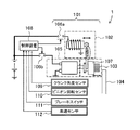
図1は、本発明の第1実施形態に係るアイドルストップシステム1の装置構成および回路接続状態を示した模式図である。本実施形態では、アイドルストップシステム1は、燃料を供給することによりクランク軸が回転するエンジン(図示せず)と、エンジンの始動をアシストするスタータ101と、スタータ101およびエンジンを制御する制御装置108とを備えている。
The present invention will be described by the following three embodiments.
[First Embodiment]
FIG. 1 is a schematic diagram showing a device configuration and a circuit connection state of an
本実施形態に係るスタータ101は、いわゆるピニオン押し出し方式のスタータであり、具体的には、エンジンの始動をアシストするスタータモータ105と、スタータモータ105により回転駆動するピニオンギア103と、ピニオンギア103を押し出すためのマグネットスイッチ102と、を少なくとも備えている。
The
スタータモータ105の回転はその内部にある減速機構で減速する。これによりスタータモータ105のトルクを増大させてピニオンギア103に伝達される。スタータモータ105は、マグネットスイッチ102に通電するとピニオンギア103を押し出して(図1の右方向)、リングギア104に噛み込ませる構造となっている。ここで、リングギア104は、エンジンのクランク軸の回転に同期するものであり、クランク軸に取付けられている。なお、ピニオンギア103を押し出す機能を備えるものであれば、本実施形態の如きマグネットスイッチに限定されるものではない。
The rotation of the
ピニオンギア103はワンウェイクラッチ107と一体化されている。上述した如く、ピニオンギア103は、制御装置108からのマグネットスイッチ102への通電により、スタータモータ105の軸方向に移動可能な構造となっている。ピニオンギア103はエンジンのクランク軸に連結されたリングギア104と噛み合わせて回転することでエンジンに動力を伝えることができる。
The
ワンウェイクラッチ107はスタータモータ105がエンジンを正回転させる方向にしか動力が伝わらない構成にする。これにより、ピニオンギア103がリングギア104に噛み合っている時は、リングギア104の回転数は、スタータモータ105の回転数に対して、減速比に応じた同期回転数になるか、もしくは、それよりも速い回転数になる。
The one-
すなわち、リングギア104がピニオンギア103の回転速数よりも低下しようとすると、ワンウェイクラッチ107が動力を伝達するため、リングギア104の回転数がスタータモータ105に対する同期回転数を下回ることはない。一方で、同期回転数よりもリングギアの回転数の方が高い時は、ワンウェイクラッチが動力を伝達しないため、リングギア104からスタータモータ105側へ動力が伝達されることはない。
That is, if the
図1に示すように、アイドルストップシステム1は、燃料を供給することによりクランク軸が回転するエンジンと、クランク軸の回転に同期したリングギア104と、エンジンの始動をアシストするスタータモータ105と、エンジンの始動をアシストする際にリングギア104に噛み込むとともにスタータモータ105により回転駆動するピニオンギア103とを少なくとも備えている。
As shown in FIG. 1, the
図1に示す通り、クランク角度センサ109(エンジン回転数検出装置、クランク角度検出装置)からの信号、ピニオン回転センサ110(ピニオン回転数検出装置)、ブレーキスイッチ111、車速センサ112からの信号は制御装置108に入力される。なお、リングギア104とエンジンのクランク軸は連結されているので、リングギア回転数とクランク軸回転数(エンジン回転数)は同義である。
As shown in FIG. 1, signals from the crank angle sensor 109 (engine speed detector, crank angle detector), signals from the pinion speed sensor 110 (pinion speed detector), the
制御装置108は、通常の燃料噴射制御(燃料噴射弁の制御)、点火(点火プラグの制御)、空気制御(電子制御スロットルの制御)を行っている。これに加えて、制御装置108は、ブレーキスイッチからの信号に基づくブレーキペダル状態、車速センサ112からの車速等の各種情報(車両の運転状態)から、アイドルストップ条件の成立を判定する。ここで、アイドルストップ条件が成立した場合には、エンジンのアイドルストップを許可し、燃料噴射弁を制御することによりエンジンへの燃料の供給を停止し、これによりエンジンを自動停止させる(アイドルストップさせる)。
The
上述した車両の運転状態から、エンジンの再始動要求が発生した時には、制御装置は、燃料噴射弁を制御することによりエンジンへの燃料供給の再開をするとともに、点火プラグを制御することにより点火タイミングを制御する。このようにしてエンジン再始動制御が実行される。 When an engine restart request is generated from the vehicle operating state described above, the control device restarts the fuel supply to the engine by controlling the fuel injection valve, and controls the spark plug to control the ignition timing. To control. In this way, engine restart control is executed.
また、制御装置108からはピニオン押し出し指令信号とモータ回転指令信号がそれぞれ独立して出力される。図1で示す通り、ピニオン押し出し指令信号を伝えるマグネットスイッチ通電用スイッチ106aとモータ回転指令信号を伝えるスタータモータ通電用スイッチ106bが、ピニオンギア103の押し出しとスタータモータ105の回転とを制御する。マグネットスイッチ通電用スイッチ106aおよびスタータモータ通電用スイッチ106bとして、例えば機械式接点を持つリレースイッチや、半導体を用いたスイッチなどを使うことができる。
The
このような装置構成からなるアイドルストップシステム1において、制御装置108は、以下の如き制御を行う。図2は、本発明の第1実施形態に係るアイドルストップシステムを制御する制御装置の制御ブロック図である。
In the
図1に示す制御装置108は、上述した車両の運転状態を検出するセンサの出力信号をA/D変換器を介して入力し、入力したデータおよび予めメモリー等で記憶されたデータに基づいて以下に示す演算等をCPUで行い、A/D変換器を介して制御信号を出力することによりアイドルストップシステム1を制御する。
The
ソフトウエアの構成として、制御装置108は、少なくとも図2に示すよう制御ブロックで構成される。具体的には、アイドルストップ判定部201は、車速センサからの車速信号、ブレーキスイッチ信号、リングギア回転数等により車両がアイドルストップの条件が成立しているかを判定する。燃料供給停止部202は、アイドルストップ判定部201でアイドルストップの条件が成立したときにエンジンへの燃料供給の停止を行う。燃料供給停止部202は、具体的には、エンジン内で燃料の燃焼が行われないように、燃料噴射弁の制御を行う。この際、必要に応じて点火プラグによる点火を停止するように、点火プラグの制御も行ってよい。
As a software configuration, the
ここで、燃料供給停止部202でエンジンへの燃料供給が停止した際には、エンジン回転数が低下する。そこで、惰性回転判定部203では、エンジンの再始動要求がされた際に、エンジンが惰性回転しているかどうかを判定する。具体的には、燃料供給停止部202により燃料供給が停止してからクランク軸(エンジン)の回転が停止するまでの間のエンジン惰性回転中であるか否かを判定する。より具体的なエンジン惰性回転中であるか否かの判定は、リングギア回転数(エンジン回転数)またはその変化量(クランク角度の変化度合い)に基づいて行う。
Here, when the fuel supply to the engine is stopped by the fuel
ここで、エンジンの再始動要求がされたか否かの判定は、再始動要求判定部204で、ブレーキスイッチの信号等に基づいて行われる。たとえば、ブレーキスイッチがオフの場合、エンジンの再始動要求がされたと判定される。燃焼復帰部205は、上述した燃焼復帰の条件が成立したときに、燃料噴射量の制御、点火タイミングの制御、および吸入空気量の制御を行うべく、燃料噴射弁、燃料点火プラグ、およびスロットル弁に制御信号を出力する。燃焼復帰部205は、惰性回転判定部203がエンジン惰性回転中であると判定したときに、エンジンに燃料を供給し、供給した燃料を燃焼する。
Here, whether or not an engine restart request has been made is determined by the restart
再始動アシスト判定部207は、燃焼復帰部205によりエンジンへの燃料の供給の開始後、エンジンの運転状態に基づいて、スタータによるエンジンの再始動のアシストを行うか否かを判定する。具体的には、燃焼復帰部205のみにより燃焼復帰始動を行うか、または、これに加えてスタータによるエンジンの再始動のアシストをさらに行うかの判定をエンジン回転数(リングギア回転数)から行う。
After the start of fuel supply to the engine by the
また、再始動アシスト判定部207は、燃焼復帰部205により燃料が最初に供給された気筒が燃料供給後の膨張行程に達する(具体的には供給された燃料が点火される)までの間(第1の期間)であるか、それとも、膨張行程以降(第2の期間)であるか、現状のエンジンの状態を判定する。そして、第1の期間である場合には、リングギアの回転数とピニオンギアの回転数との回転数差に基づき、スタータ101によるエンジンの再始動のアシストを行うタイミングを決定する。
Further, the restart assist
ここで、リングギアの回転数とピニオンギアの回転数との回転数差は、回転数差演算部で演算され、この回転数差が所定値以下になったときに、再始動アシスト判定部207は、スタータ101による再始動アシストの許可信号を出力する。一方、第2の期間である場合には、エンジンの状態(エンジン回転数)によっては燃焼復帰部205のみにより燃焼復帰始動を行うことができることもある。したがって、エンジン回転数が所定の回転数以下である場合に、スタータモータによるエンジンの再始動のアシストを行う。
Here, the rotation speed difference between the rotation speed of the ring gear and the rotation speed of the pinion gear is calculated by a rotation speed difference calculation unit, and when this rotation speed difference becomes a predetermined value or less, the restart assist
再始動アシスト部208は、再始動アシストの許可信号が出力されたタイミングで、リングギア104をピニオンギア103に噛み込ませ、スタータモータ105を駆動することによりエンジンの再始動をアシストする。具体的には、再始動アシスト部208はピニオン押し出し指令信号とモータ回転指令信号とを出力し、マグネットスイッチ通電用スイッチ106aとスタータモータ通電用スイッチ106bを制御する。これにより、エンジンの再始動のアシストが実行される。
The
ここで、本実施形態では、制御装置1はエンジン回転数低下部209をさらに備えており、エンジン回転数低下部209は再始動アシスト判定部207がエンジンの再始動アシストを行うと判定してから、再始動アシスト部208が、リングギアをピニオンギアに噛み込ませるまで(具体的にはピニオン押し出し指令信号を出力するまで)の間のエンジンの回転数を低下させる。本実施形態では、エンジン回転数低下部は、前記燃焼復帰部の燃料供給を禁止することにより、前記エンジンの回転数を低下させる。
Here, in the present embodiment, the
なお、惰性回転判定部203で、エンジン惰性回転中でないと判定した場合、再始動要求判定部204で再始動要求の条件が成立したときには、通常の再始動アシストを行う。この際には、再始動アシスト判定部207で再始動アシストの判定を行わず再始動アシスト部208でスタータによるエンジン再始動のアシストを行いつつ、燃焼復帰部205による燃焼復帰を行う。
When the inertial
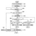
図3および図4は、図2に示す制御装置のフローチャートであり、図5は、図2に示すアイドルストップシステムのタイミングチャートを示した図である。図3に示すように、まずステップ301において、アイドルストップ判定部201がアイドルストップ条件の成立を判定した場合ステップ302に進む。ステップ302において、アイドルストップ条件の成立に応じて燃料供給停止部202が燃料供給を停止しステップ303に進む。このとき、図5に示すように、時刻t1で燃料供給停止フラグはLowからHighとなる。その結果、エンジン回転は惰性回転を始める。
3 and 4 are flowcharts of the control device shown in FIG. 2, and FIG. 5 is a diagram showing a timing chart of the idle stop system shown in FIG. As shown in FIG. 3, when the idle
次にステップ303では、再始動要求判定部204は再始動要求が発生したかを判定する。ステップ303で再始動要求が発生したと判定された場合には(図5における時刻t2)、ステップ304に進み、惰性回転判定部203はエンジン惰性回転中であるか否かを判定する。エンジン惰性回転中であるか否かの判定は、例えば、エンジン回転数から判定してもよいし、クランク角度の変化度合いから判定してもよい。
In
ここで、再始動要求判定部204で再始動要求がされていると判定し、ステップ304において惰性回転判定部203がエンジン惰性回転中でないと判定した場合、エンジン回転数とピニオンギアの回転数はどちらも0r/minであり、同期しているため、ステップ321に進み、通常の再始動制御を行う。
Here, when it is determined that the restart request is determined by the restart
通常の再始動制御では、上述したように、再始動アシスト部208からの押出し指令信号により、マグネットスイッチ102に通電してピニオンギア103を押し出してリングギア104に噛み合わせる。次に、再始動アシスト部208からのモータ回転指令信号により、スタータモータ105に通電する。これによりエンジンをクランキングして、燃焼復帰部205により燃料供給を再開し(燃焼復帰をし)、エンジンを再始動させる。
In normal restart control, as described above, the
一方、ステップ304においてエンジン惰性回転中と判定した場合には、ステップ305に進み、燃焼復帰部205で燃料供給を再開し、ステップ306に進む。ステップ306では、エンジン回転数Ne1の読み込みタイミングに達しているか判定する。
On the other hand, if it is determined in
具体的には、エンジン回転数Ne1の読み込みタイミングは、燃料供給を最初に再開した気筒のクランク角度が、膨張行程以降のタイミングを想定している。すなわち、ステップ305で燃料供給を再開し、燃焼による再始動の実行を要求しても、直ちにエンジンの回転速度が上昇する訳でなく、一定期間の経過を待たなければならない。これは、吸気ポートに燃料を噴射するPFIエンジンを例にすると、燃料供給の再開から、最初に燃料噴射を行った気筒において、燃料噴射を行う吸気行程から燃焼トルクを得ることができる膨張行程まで時間を要するためである。
Specifically, the reading timing of the engine speed Ne1 is assumed to be the timing after the expansion stroke of the crank angle of the cylinder in which fuel supply is first resumed. That is, even if the fuel supply is resumed in
ここで、ステップ306で、エンジン回転数Ne1の読み込みタイミングに達しているかを判定し、条件が成立した場合(図5における時刻3)、ステップ307へ進む。すなわち、この条件が成立した場合、燃料を再度供給した最初の気筒が膨張行程以降のときの状態にある。ステップ307では、燃焼復帰部205により、エンジン回転数Ne1が燃焼復帰判定基準値NeJDGを超えているかを判定し、この条件が成立した場合(Ne1>NeJDG)、ステップ313へ進み、燃焼復帰始動と判定し、燃焼のみで再始動を行う。
Here, in
一方、ステップ307でエンジン回転数Ne1がNeJDG以下の場合(Ne1≦NeJDG)、ステップ308に進み、ステップ308で再始動アシスト判定部207により予回転スタータアシスト始動と判定し、ステップ309に進む(図4を参照)。
On the other hand, if the engine speed Ne1 is equal to or lower than NeJDG in step 307 (Ne1 ≦ NeJDG), the process proceeds to step 308, and in
図4に示すように、ステップ309では、エンジン回転数低下部209が、燃焼復帰部205の燃料供給を禁止(停止)することによりエンジンの回転数を低下させる。次に、ステップ310にてスタータモータ105に通電を行い、ピニオンギア103を予回転させる。これによりピニオンギア103が回転運動を始め、ピニオンギア103の回転数が上昇する。本明細書では、リングギアに噛み込み前にこの通電によるスタータモータの回転を「予回転」と称する。
As shown in FIG. 4, in
次にステップ311において、再始動アシスト判定部207でエンジン回転数Neとピニオンギア103の回転数Npの回転数差がピニオン押し出し許可回転数差PIJDG2以下であるか否かを判定する。条件が成立した場合((Ne−Np)≦PIJDG2),図5の時刻t4)、ステップ312へ進み、再始動アシスト部208でスタータモータ105の通電を止めるとピニオンギアは惰性回転を続ける。
Next, at
次に、ステップ317では、ピニオンギア103を押し出すためのマグネットスイッチ102に通電を行う。これにより、回転数差が小さい状態でリングギア104に向かってピニオンギア103が押し出されることによりピニオンギア103とリングギア104が噛み込む際の衝撃が緩和され、衝突音、噛み込み音が低減されると共にピニオンギア103とリングギア104の磨耗が緩和できる。
Next, in Step 317, the
次にステップ318で、ピニオンギア103がリングギア104に噛み込んだか否かを判定する。噛み込み判定は、ステップ317のピニオン押し出し通電開始から所定時間(図5における時刻t4から時刻t5までの期間)経過後、噛み込み完了と判定してよい。つまり、時刻t4から時刻t5までの期間とはピニオン押し出し通電開始からピニオンギア103が移動してリングギア104に到達しリングギアに噛み込んでいくまでの時間である。もしくは、ピニオンギア103とリングギア104が噛み込んだことを検出可能なセンサを設けておき、センサの出力値に基づいて噛み込み完了と判定してもよい。条件が成立した場合(図5における時刻t5)、ステップ320にてスタータモータに通電してエンジンをクランキングして再始動させる。
Next, at
一方、ステップ306でエンジン回転数Ne1の読み込みタイミングの条件が成立していない場合、すなわち、燃焼復帰部205により燃料が最初に供給された気筒が燃料供給後の膨張行程に達するまでの間の状態である場合には、エンジン回転数Ne1の読み込みタイミングの条件が成立を待たずに、ステップ314に進む。ステップ314では、回転数差演算部がエンジン回転数Neとピニオン回転数Npとの回転数差(Ne−Np)を演算し、再始動アシスト判定部207は、演算された回転数差(Ne−Np)がピニオン押し出し許可回転数差PIJDG1以下であるか否かを判定する。
On the other hand, if the condition for the reading timing of the engine speed Ne1 is not satisfied in
この条件が成立した場合((Ne−Np)≦PIJDG1)、ステップ315に進み、ステップ315では再始動アシスト判定部207によりスタータアシスト始動と判定し、ステップ316に進む(図4参照)。このようにして、燃焼復帰部205により燃料が最初に供給された気筒が燃料供給後の膨張行程に達するまでの間に、スタータによるエンジンの再始動のアシストを行うか否かを判定することができるため、後述するエンジンの再始動のアシストを迅速に行うことができる。
When this condition is satisfied ((Ne−Np) ≦ PIJDG1), the process proceeds to step 315. In
ステップ316では、図4に示すように、エンジン回転数低下部209が、燃焼復帰部205の燃料供給を禁止(停止)することによりエンジンの回転数を低下させ、ステップ317に進む。ステップ317ではピニオンギア103を押し出すためのマグネットスイッチ102に通電を行う。ステップ318にてピニオンギア103がリングギア104に噛み込んだか否かを判定する。条件が成立した場合、ステップ319にてスタータモータに通電してエンジンをクランキングして、次にステップ320にて燃料供給を再開し、エンジンを再始動させる。
In
従来の方式は、スタータアシスト始動と判定しても燃料供給を継続するのと比較して、本発明の方式は、図5における時刻t3のタイミングでスタータアシスト始動と判定すると、燃料供給を停止することにより、燃焼によるエンジン回転数の上昇がなくなり、エンジン回転数が速やかに低下し、ピニオンとリングギアが噛み込むまでの時間(図5における時刻t3から時刻t5の期間)が短縮され、再始動時間が短縮される。 Compared to the case where the conventional method continues the fuel supply even if the starter assist start is determined, the method of the present invention stops the fuel supply when the starter assist start is determined at the time t3 in FIG. As a result, the engine speed is not increased due to combustion, the engine speed is quickly decreased, and the time until the pinion and the ring gear are engaged (the period from time t3 to time t5 in FIG. 5) is shortened and restarted. Time is shortened.
〔第2実施形態〕
図6は第2実施形態に係るアイドルストップシステムの制御装置のフローチャートである。図7は、図6に示すフローの続きを示したフローチャートである。図8は、第2実施形態に係るアイドルストップシステムのタイミングチャートを示した図である。
[Second Embodiment]
FIG. 6 is a flowchart of the control device of the idle stop system according to the second embodiment. FIG. 7 is a flowchart showing a continuation of the flow shown in FIG. FIG. 8 is a diagram showing a timing chart of the idle stop system according to the second embodiment.
第2実施形態に係る制御装置が、第1実施形態に係る制御装置と相違する点は、図7に示すように、燃料供給停止部202により燃料の供給を停止(禁止)してから、ピニオンを押し出すまでの間、スタータモータでリングギアに噛み込み前のピニオンギアを予回転させていない点である。図6および図7に示すステップのうち、第1実施形態の図3および図4に示す一連のステップと同じステップは、下2ケタの数字に同じ数字を付して、その詳細な説明は省略する。 The control device according to the second embodiment is different from the control device according to the first embodiment in that, as shown in FIG. The pinion gear before being engaged with the ring gear by the starter motor is not pre-rotated until it is pushed out. Of the steps shown in FIGS. 6 and 7, the same steps as the series of steps shown in FIGS. 3 and 4 of the first embodiment are given the same numbers in the last two digits, and detailed descriptions thereof are omitted. To do.
第1実施形態では、スタータアシスト始動と判定した場合、スタータモータ105に通電を行ない、ピニオンギア103の回転数を上昇させてからピニオンギア103とリングギア104を噛み込ませたが、第2の実施形態では、第1の実施形態の図4に示すステップ310およびステップ312が省略されているため、スタータアシスト始動と判定した場合、ピニオンの回転数を上昇させずに、エンジン回転数が低下するのを待ってピニオンとリングギアを噛み込ませることになる。これにより、ピニオンギアがリングギアに噛み込むまでの時間は長くなるが、回転数差演算部が不要となり、第1実施形態の如く、モータ回転指令とピニオン押し出し指令を独立して指令する必要が無くなる利点がある。
In the first embodiment, when it is determined that the starter assist start is performed, the
〔第3実施形態〕
図9は、第3実施形態に係るアイドルストップシステムの制御装置のフローチャートである。図10は、図9に示すフローの続きを示したフローチャートである。図11は、第3実施形態に係るアイドルストップシステムのタイミングチャートを示した図である。
[Third Embodiment]
FIG. 9 is a flowchart of the control device of the idle stop system according to the third embodiment. FIG. 10 is a flowchart showing a continuation of the flow shown in FIG. FIG. 11 is a diagram illustrating a timing chart of the idle stop system according to the third embodiment.
第3実施形態に係る制御装置が、第1実施形態に係る制御装置と相違する点は、第1実施形態では、エンジン回転数低下部が、燃焼復帰部の燃料供給を禁止することにより、前記エンジンの回転数を低下させていたが、第3実施形態では、エンジン回転数低下部が、再始動アシストを行うと判定する前の燃料の点火時期よりも、燃料の点火時期を遅角することにより、前記エンジンの回転数を低下させている点である。具体的には、一連の制御フローにおいて、図10に示すステップ909,916のみが相違する。 The control device according to the third embodiment is different from the control device according to the first embodiment in that, in the first embodiment, the engine speed reduction unit prohibits the fuel supply of the combustion return unit, thereby Although the engine speed has been reduced, in the third embodiment, the engine speed reduction unit retards the fuel ignition timing before it is determined to perform the restart assist. Thus, the number of revolutions of the engine is reduced. Specifically, only steps 909 and 916 shown in FIG. 10 are different in a series of control flows.
従って、図3および図4に示すステップのうち、ステップ309、316以外の第1実施形態の図3および図4に示す一連のステップと同じステップは、下2ケタの数字に同じ数字を付して(上1ケタを3から9の数字に変更して)、その詳細な説明は省略する。
このように、第1実施形態のように、ステップ309、316で燃焼復帰部の燃料供給を禁止することにより、前記エンジンの回転数を低下させる代わりに、第3実施形態の如く、ステップ909およびステップ916で、再始動アシストを行うと判定する前の燃料の点火時期よりも、燃料の点火時期を遅角することにより、前記エンジンの回転数を低下させる。
Therefore, among the steps shown in FIGS. 3 and 4, the same steps as the series of steps shown in FIGS. 3 and 4 of the first embodiment other than
Thus, as in the first embodiment, instead of reducing the engine speed by prohibiting the fuel supply of the combustion return part in
具体的には、再始動アシスト判定部207がスタータモータによるエンジンの再始動アシストを行うと判定してから、再始動アシスト部208がリングギア104をピニオンギア103に噛み込ませるまでの間の少なくとも一部の期間において、エンジン回転数低下部209は、再始動アシストを行うと判定するタイミング前の燃料の点火時期(または、図11に示す燃料供給を停止する前の点火時期ADV1)よりも、燃料の点火時期を遅角させることにより、エンジンの回転数を低下させる。このようにして、燃料の点火時期を遅角させることにより、燃焼によるエンジン回転数の上昇が小さくなり、エンジン回転数が速やかに低下し、ピニオンとリングギアが噛み込むまでの時間(図11における時刻t3から時刻t5の期間)が短縮され、再始動時間が短縮される。
Specifically, at least from when it is determined that the restart assist
第3実施形態では、第1実施形態のステップ309、316で燃焼復帰部の燃料供給を禁止することにより、エンジンの回転数を低下させる代わりに、ステップ909およびステップ916で、再始動アシストを行うと判定する前の燃料の点火時期よりも、燃料の点火時期を遅角することにより、エンジンの回転数を低下させた。
In the third embodiment, instead of lowering the engine speed by prohibiting the fuel supply of the combustion return portion in
この他にも、エンジンの回転数を低下させる手段として、再始動アシストを行うと判定する前のスロットル開度よりも、スロットル開度を小さくすることにより、前記エンジンの回転数を低下させてもよい。すなわち、スロットル開度を小さくすることにより(具体的にはスロットル弁の開度を減少方向に制御することにより)、吸気負圧が増大してポンピングロスが増大し、このポンピングロスの増大によってエンジン回転速度が急速に降下させることができる。 In addition to this, as a means for reducing the engine speed, it is possible to reduce the engine speed by making the throttle opening smaller than the throttle opening before determining that the restart assist is performed. Good. That is, by reducing the throttle opening (specifically, by controlling the throttle valve opening in a decreasing direction), the intake negative pressure increases and the pumping loss increases. The rotational speed can be lowered rapidly.
この他にも、エンジンに可変バルブ機構を有している場合には、エンジン回転数低下部は、再始動アシストを行うと判定する前の吸気バルブタイミングよりも、吸気バルブタイミングを遅角することにより、前記エンジンの回転数を低下させてもよい。 In addition to this, when the engine has a variable valve mechanism, the engine speed reduction unit retards the intake valve timing before the intake valve timing before determining that the restart assist is performed. Thus, the rotational speed of the engine may be reduced.
このようにして、吸入空気量または燃焼室に流入するタイミングを制御することにより、エンジンの回転数を低下させることができ、第1実施形態における、燃焼復帰部の燃料供給の禁止、第3実施形態における点火時期の遅角化と合わせて行うことにより、迅速にエンジンの回転数を低下させることができる。 In this way, by controlling the intake air amount or the timing of flowing into the combustion chamber, the engine speed can be reduced. In the first embodiment, prohibition of fuel supply to the combustion return portion, the third embodiment By performing this together with the retarding of the ignition timing in the embodiment, the engine speed can be quickly reduced.
さらに、別の態様としては、エンジン回転数低下部が、クランク軸に連結された機器を作動させて、エンジンに負荷を与えることにより、エンジンの回転数を低下させてもよい。ここでは、クランク軸に連結された機器であって、これを作動させて、エンジンに負荷を与えることができる機器は、エアコンのコンプレッサ、オルタネータなどを挙げることができる。この態様であっても、クラックシャフトの回転抵抗を高めることにより、エンジン惰性回転を速やかに下降させ、これに伴い、エンジンを速やかに再始動させることができる。 Furthermore, as another aspect, the engine speed reduction unit may reduce the engine speed by operating a device connected to the crankshaft and applying a load to the engine. Here, equipment connected to the crankshaft, which can be operated to apply a load to the engine, includes an air conditioner compressor, an alternator, and the like. Even in this aspect, by increasing the rotational resistance of the crack shaft, the engine inertia rotation can be quickly lowered, and accordingly, the engine can be restarted quickly.
尚、本発明を適用可能なエンジンは、筒内燃料噴射型のエンジンに限定されず、吸気ポートに燃料噴射する吸気ポート型のエンジンや、吸気ポートと筒内燃料噴射を併用するデュアル燃料噴射型のエンジンにも適用して実施できる。また、気筒数やエンジン形式(V型や水平対抗型)についても限定されず、適用して実施できる。 The engine to which the present invention is applicable is not limited to an in-cylinder fuel injection type engine, but is an intake port type engine that injects fuel into an intake port, or a dual fuel injection type that uses both an intake port and in-cylinder fuel injection. It can also be applied to other engines. Further, the number of cylinders and the engine type (V type or horizontal opposing type) are not limited and can be applied.
以上、図面を用いて本発明の実施の形態を詳述してきたが、具体的な構成はこの実施形態に限定されるものではなく、本発明の要旨を逸脱しない範囲における設計変更等があっても、それらは本発明に含まれるものである。 The embodiment of the present invention has been described in detail with reference to the drawings, but the specific configuration is not limited to this embodiment, and there are design changes and the like without departing from the gist of the present invention. They are also included in the present invention.
1:アイドルストップシステム
101:スタータ
102:マグネットスイッチ
103:ピニオンギア
104:リングギア
105:スタータモータ
106a:マグネットスイッチ通電用スイッチ
106b:スタータモータ通電用スイッチ
107:ワンウェイクラッチ
108:制御装置
109:クランク角度センサ
110:ピニオン回転センサ
111:ブレーキスイッチ
112:車速センサ
201:アイドルストップ判定部
202:燃料供給停止部
203:惰性回転判定部
204:再始動要求判定部
205:燃焼復帰部
207:再始動アシスト判定部
208:再始動アシスト部
209:エンジン回転数低下部
t1:燃料供給停止のタイミング
t2:再始動要求発生タイミングおよび燃料供給再開タイミング
t3:Ne1読み込みタイミング
t4:ピニオン押し出しタイミング
t5:噛み込み完了タイミングおよびクランキング開始タイミング
Ne:エンジン回転数
Np:ピニオンの回転数
Ne1:燃料供給を最初に再開した気筒のクランク角度が膨張行程以降のタイミング時のエンジン回転数
PIJDG1:ピニオン押し出し許可回転数差
PIJDG2:ピニオン押し出し許可回転数差
NeJDG:燃焼復帰判定基準値
1: Idle stop system 101: Starter 102: Magnet switch 103: Pinion gear 104: Ring gear 105:
Claims (7)
前記クランク軸の回転に同期したリングギアと、
前記エンジンの始動をアシストするスタータモータと、
前記エンジンの始動をアシストする際に前記リングギアに噛み込むとともに前記スタータモータにより回転駆動するピニオンギアと、を備え、
エンジン運転中に所定のアイドルストップ条件が成立したときに前記エンジンへ燃料の供給を停止することにより、前記エンジンを自動停止させるアイドルストップシステムの制御装置であって、
前記制御装置は、前記エンジン運転中に前記所定のアイドルストップ条件が成立したときに、前記エンジンへ燃料の供給を停止する燃料供給停止部と、
前記エンジンの再始動要求がされた際に、前記燃料供給停止部により燃料供給が停止してから前記クランク軸の回転が停止するまでの間のエンジン惰性回転中であるか否かを判定する惰性回転判定部と、
前記惰性回転判定部が、前記エンジン惰性回転中であると判定したときに、前記エンジンに燃料を供給し、前記供給した燃料を燃焼する燃焼復帰部と、
前記燃焼復帰部により前記エンジンへの燃料の供給の開始後、前記エンジンの運転状態に基づいて、前記スタータモータによる前記エンジンの再始動のアシストを行うか否かを判定する再始動アシスト判定部と、
前記再始動アシスト判定部が前記スタータモータによる前記エンジンの再始動アシストを行うと判定したときに、前記リングギアを前記ピニオンギアに噛み込ませた後、前記スタータモータを駆動することにより前記エンジンの再始動をアシストする再始動アシスト部と、
前記再始動アシスト判定部が、前記スタータモータによる前記エンジンの再始動アシストを行うと判定してから、前記再始動アシスト部が、前記リングギアを前記ピニオンギアに噛み込ませるまでの間の少なくとも一部の期間において、前記エンジンの回転数を低下させるエンジン回転数低下部と、を少なくとも備え、
前記再始動アシスト判定部は、前記エンジンの運転状態として、前記燃焼復帰部により燃料が最初に供給された気筒が燃料供給後の膨張行程に達するまでの第1の期間と、前記膨張行程以降の第2の期間を判定し、判定された前記第1の期間および第2の期間において、前記再始動のアシストを行うか否かを判定することを特徴とするアイドルストップシステムの制御装置。 An engine whose crankshaft rotates by supplying fuel;
A ring gear synchronized with the rotation of the crankshaft;
A starter motor that assists in starting the engine;
A pinion gear that engages with the ring gear when assisting the start of the engine and is rotationally driven by the starter motor, and
A control device for an idle stop system that automatically stops the engine by stopping the supply of fuel to the engine when a predetermined idle stop condition is satisfied during engine operation,
The control device includes a fuel supply stop unit that stops supply of fuel to the engine when the predetermined idle stop condition is satisfied during the engine operation,
Inertia for determining whether or not the engine is rotating in an interval from when the fuel supply is stopped by the fuel supply stop unit until the rotation of the crankshaft is stopped when the engine restart request is made. A rotation determination unit;
A combustion return unit for supplying fuel to the engine and burning the supplied fuel when the inertia rotation determination unit determines that the engine inertia is rotating;
A restart assist determination unit that determines whether or not to assist restart of the engine by the starter motor based on an operating state of the engine after the start of fuel supply to the engine by the combustion return unit; ,
When the restart assist determination unit determines to perform the engine restart assist by the starter motor, the ring gear is engaged with the pinion gear, and then the starter motor is driven to drive the engine. A restart assist unit for assisting restart;
After the restart assist determination unit determines that the engine is to be restarted by the starter motor, at least one of the period from when the restart assist unit causes the ring gear to be engaged with the pinion gear. An engine rotation speed reduction unit that reduces the rotation speed of the engine in a period of a part,
The restart assist determination unit includes, as an operating state of the engine, a first period until a cylinder to which fuel is first supplied by the combustion return unit reaches an expansion stroke after fuel supply, and after the expansion stroke. A control apparatus for an idle stop system, characterized in that a second period is determined, and whether or not the restart assist is performed in the determined first period and second period .
前記エンジンの始動をスタータモータでアシストする際に、前記エンジンのリングギアにピニオンギアを噛み込ませて回転駆動するアイドルストップシステムの制御装置であって、
前記制御装置は、前記所定のアイドルストップ条件成立後の惰性回転中に、前記エンジンの再始動要求がされた際に、前記エンジンに燃料を供給し、該供給した燃料を燃焼する燃焼復帰部と、
前記燃焼復帰部により前記エンジンへの燃料の供給の開始後、前記エンジンの運転状態に基づいて、前記スタータモータによる前記エンジンの再始動のアシストを行うか否かを判定する再始動アシスト判定部と、
前記再始動アシスト判定部が前記アシストを行うと判定してから前記リングギアを前記ピニオンギアに噛み込ませるまでの間の少なくとも一部の期間において、前記エンジンの回転数を低下させるエンジン回転数低下部と、を少なくとも備え、
前記再始動アシスト判定部は、前記エンジンの運転状態として、前記燃焼復帰部により燃料が最初に供給された気筒が燃料供給後の膨張行程に達するまでの第1の期間と、前記膨張行程以降の第2の期間を判定し、判定された前記第1の期間および第2の期間において、前記再始動のアシストを行うか否かを判定することを特徴とするアイドルストップシステムの制御装置。 By stopping the supply of fuel to the engine when a predetermined idle stop condition is satisfied, the engine is automatically stopped,
When assisting the start of the engine with a starter motor, a control device for an idle stop system that rotates by driving a pinion gear into a ring gear of the engine,
The control device includes a combustion return unit that supplies fuel to the engine when the engine is requested to restart during inertial rotation after the predetermined idle stop condition is satisfied, and burns the supplied fuel. ,
A restart assist determination unit that determines whether or not to assist restart of the engine by the starter motor based on an operating state of the engine after the start of fuel supply to the engine by the combustion return unit; ,
Decreasing the engine speed for reducing the engine speed in at least a part of the period from when the restart assist determination unit determines that the assist is performed until the ring gear is engaged with the pinion gear And at least
The restart assist determination unit includes, as an operating state of the engine, a first period until a cylinder to which fuel is first supplied by the combustion return unit reaches an expansion stroke after fuel supply, and after the expansion stroke. A control apparatus for an idle stop system, characterized in that a second period is determined, and whether or not the restart assist is performed in the determined first period and second period .
前記エンジン回転数低下部は、再始動アシストを行うと判定する前の吸気バルブタイミングよりも、吸気バルブタイミングを遅角することにより、前記エンジンの回転数を低下させることを特徴とする請求項1または2に記載のアイドルストップシステムの制御装置。 The engine has a variable valve mechanism,
The engine speed reduction unit reduces the engine speed by retarding an intake valve timing with respect to an intake valve timing before determining that restart assistance is performed. Or a control device for an idle stop system according to 2.
Priority Applications (1)
| Application Number | Priority Date | Filing Date | Title |
|---|---|---|---|
| JP2014019639A JP6203653B2 (en) | 2014-02-04 | 2014-02-04 | Control device for idle stop system |
Applications Claiming Priority (1)
| Application Number | Priority Date | Filing Date | Title |
|---|---|---|---|
| JP2014019639A JP6203653B2 (en) | 2014-02-04 | 2014-02-04 | Control device for idle stop system |
Publications (3)
| Publication Number | Publication Date |
|---|---|
| JP2015148150A JP2015148150A (en) | 2015-08-20 |
| JP2015148150A5 JP2015148150A5 (en) | 2016-06-09 |
| JP6203653B2 true JP6203653B2 (en) | 2017-09-27 |
Family
ID=53891710
Family Applications (1)
| Application Number | Title | Priority Date | Filing Date |
|---|---|---|---|
| JP2014019639A Expired - Fee Related JP6203653B2 (en) | 2014-02-04 | 2014-02-04 | Control device for idle stop system |
Country Status (1)
| Country | Link |
|---|---|
| JP (1) | JP6203653B2 (en) |
Family Cites Families (3)
| Publication number | Priority date | Publication date | Assignee | Title |
|---|---|---|---|---|
| JP4276680B2 (en) * | 2007-02-06 | 2009-06-10 | 株式会社日本自動車部品総合研究所 | Control device for multi-cylinder internal combustion engine |
| JP5822754B2 (en) * | 2012-02-16 | 2015-11-24 | 日立オートモティブシステムズ株式会社 | Engine control system for idle stop |
| JP2013194707A (en) * | 2012-03-22 | 2013-09-30 | Denso Corp | Engine-driven auxiliary control device |
-
2014
- 2014-02-04 JP JP2014019639A patent/JP6203653B2/en not_active Expired - Fee Related
Also Published As
| Publication number | Publication date |
|---|---|
| JP2015148150A (en) | 2015-08-20 |
Similar Documents
| Publication | Publication Date | Title |
|---|---|---|
| JP5214006B2 (en) | ENGINE CONTROL DEVICE AND ENGINE CONTROL METHOD | |
| JP5188627B2 (en) | Engine starter | |
| JP5901763B2 (en) | Engine starting device and engine starting method | |
| JP2011169225A (en) | Engine automatic stop/restart device | |
| US20110172900A1 (en) | Controller for Idle Stop System | |
| JP5470241B2 (en) | Vehicle control device | |
| JP2008121648A (en) | Control unit of internal combustion engine | |
| WO2014156320A1 (en) | Onboard controller | |
| JP5624065B2 (en) | Rotational speed prediction control device and idle stop control device for internal combustion engine | |
| JP2011252407A (en) | Starter of internal combustion engine | |
| US20110207579A1 (en) | Gear engagement control system and method | |
| JP6076485B2 (en) | Engine automatic stop / restart device | |
| JP5777542B2 (en) | Idle stop control device for internal combustion engine | |
| WO2012063732A1 (en) | Vehicle control device | |
| JP5331752B2 (en) | Control device for internal combustion engine | |
| JP6203653B2 (en) | Control device for idle stop system | |
| JP5822754B2 (en) | Engine control system for idle stop | |
| GB2517752A (en) | A method of controlling the engagement of a starter motor used for starting an engine of a motor vehicle | |
| WO2016194605A1 (en) | Engine starter device for vehicles | |
| JP2015140688A (en) | Idling stop system control device | |
| JP6035616B2 (en) | Idle stop control device for internal combustion engine | |
| JP2013142289A (en) | Idling stop control device | |
| JP5561128B2 (en) | Engine automatic stop / start control device | |
| JP6759684B2 (en) | Vehicle drive controller and program | |
| JP6319071B2 (en) | System control unit |
Legal Events
| Date | Code | Title | Description |
|---|---|---|---|
| A521 | Request for written amendment filed |
Free format text: JAPANESE INTERMEDIATE CODE: A523 Effective date: 20160411 |
|
| A621 | Written request for application examination |
Free format text: JAPANESE INTERMEDIATE CODE: A621 Effective date: 20160411 |
|
| A131 | Notification of reasons for refusal |
Free format text: JAPANESE INTERMEDIATE CODE: A131 Effective date: 20161220 |
|
| A977 | Report on retrieval |
Free format text: JAPANESE INTERMEDIATE CODE: A971007 Effective date: 20161222 |
|
| A521 | Request for written amendment filed |
Free format text: JAPANESE INTERMEDIATE CODE: A523 Effective date: 20170217 |
|
| A131 | Notification of reasons for refusal |
Free format text: JAPANESE INTERMEDIATE CODE: A131 Effective date: 20170627 |
|
| A521 | Request for written amendment filed |
Free format text: JAPANESE INTERMEDIATE CODE: A523 Effective date: 20170712 |
|
| TRDD | Decision of grant or rejection written | ||
| A01 | Written decision to grant a patent or to grant a registration (utility model) |
Free format text: JAPANESE INTERMEDIATE CODE: A01 Effective date: 20170801 |
|
| A61 | First payment of annual fees (during grant procedure) |
Free format text: JAPANESE INTERMEDIATE CODE: A61 Effective date: 20170830 |
|
| R150 | Certificate of patent or registration of utility model |
Ref document number: 6203653 Country of ref document: JP Free format text: JAPANESE INTERMEDIATE CODE: R150 |
|
| S533 | Written request for registration of change of name |
Free format text: JAPANESE INTERMEDIATE CODE: R313533 |
|
| R350 | Written notification of registration of transfer |
Free format text: JAPANESE INTERMEDIATE CODE: R350 |
|
| LAPS | Cancellation because of no payment of annual fees |