JP5444503B2 - Engine starter - Google Patents
Engine starter Download PDFInfo
- Publication number
- JP5444503B2 JP5444503B2 JP2013506983A JP2013506983A JP5444503B2 JP 5444503 B2 JP5444503 B2 JP 5444503B2 JP 2013506983 A JP2013506983 A JP 2013506983A JP 2013506983 A JP2013506983 A JP 2013506983A JP 5444503 B2 JP5444503 B2 JP 5444503B2
- Authority
- JP
- Japan
- Prior art keywords
- pinion gear
- gear
- teeth
- engine
- serration
- Prior art date
- Legal status (The legal status is an assumption and is not a legal conclusion. Google has not performed a legal analysis and makes no representation as to the accuracy of the status listed.)
- Expired - Fee Related
Links
Images


Classifications
-
- F—MECHANICAL ENGINEERING; LIGHTING; HEATING; WEAPONS; BLASTING
- F02—COMBUSTION ENGINES; HOT-GAS OR COMBUSTION-PRODUCT ENGINE PLANTS
- F02N—STARTING OF COMBUSTION ENGINES; STARTING AIDS FOR SUCH ENGINES, NOT OTHERWISE PROVIDED FOR
- F02N11/00—Starting of engines by means of electric motors
-
- F—MECHANICAL ENGINEERING; LIGHTING; HEATING; WEAPONS; BLASTING
- F02—COMBUSTION ENGINES; HOT-GAS OR COMBUSTION-PRODUCT ENGINE PLANTS
- F02N—STARTING OF COMBUSTION ENGINES; STARTING AIDS FOR SUCH ENGINES, NOT OTHERWISE PROVIDED FOR
- F02N15/00—Other power-operated starting apparatus; Component parts, details, or accessories, not provided for in, or of interest apart from groups F02N5/00 - F02N13/00
- F02N15/02—Gearing between starting-engines and started engines; Engagement or disengagement thereof
- F02N15/04—Gearing between starting-engines and started engines; Engagement or disengagement thereof the gearing including disengaging toothed gears
- F02N15/06—Gearing between starting-engines and started engines; Engagement or disengagement thereof the gearing including disengaging toothed gears the toothed gears being moved by axial displacement
- F02N15/062—Starter drives
-
- F—MECHANICAL ENGINEERING; LIGHTING; HEATING; WEAPONS; BLASTING
- F02—COMBUSTION ENGINES; HOT-GAS OR COMBUSTION-PRODUCT ENGINE PLANTS
- F02N—STARTING OF COMBUSTION ENGINES; STARTING AIDS FOR SUCH ENGINES, NOT OTHERWISE PROVIDED FOR
- F02N15/00—Other power-operated starting apparatus; Component parts, details, or accessories, not provided for in, or of interest apart from groups F02N5/00 - F02N13/00
- F02N15/02—Gearing between starting-engines and started engines; Engagement or disengagement thereof
- F02N15/04—Gearing between starting-engines and started engines; Engagement or disengagement thereof the gearing including disengaging toothed gears
- F02N15/06—Gearing between starting-engines and started engines; Engagement or disengagement thereof the gearing including disengaging toothed gears the toothed gears being moved by axial displacement
-
- F—MECHANICAL ENGINEERING; LIGHTING; HEATING; WEAPONS; BLASTING
- F16—ENGINEERING ELEMENTS AND UNITS; GENERAL MEASURES FOR PRODUCING AND MAINTAINING EFFECTIVE FUNCTIONING OF MACHINES OR INSTALLATIONS; THERMAL INSULATION IN GENERAL
- F16H—GEARING
- F16H1/00—Toothed gearings for conveying rotary motion
- F16H1/02—Toothed gearings for conveying rotary motion without gears having orbital motion
- F16H1/04—Toothed gearings for conveying rotary motion without gears having orbital motion involving only two intermeshing members
- F16H1/06—Toothed gearings for conveying rotary motion without gears having orbital motion involving only two intermeshing members with parallel axes
-
- F—MECHANICAL ENGINEERING; LIGHTING; HEATING; WEAPONS; BLASTING
- F16—ENGINEERING ELEMENTS AND UNITS; GENERAL MEASURES FOR PRODUCING AND MAINTAINING EFFECTIVE FUNCTIONING OF MACHINES OR INSTALLATIONS; THERMAL INSULATION IN GENERAL
- F16H—GEARING
- F16H55/00—Elements with teeth or friction surfaces for conveying motion; Worms, pulleys or sheaves for gearing mechanisms
- F16H55/02—Toothed members; Worms
- F16H55/08—Profiling
-
- F—MECHANICAL ENGINEERING; LIGHTING; HEATING; WEAPONS; BLASTING
- F02—COMBUSTION ENGINES; HOT-GAS OR COMBUSTION-PRODUCT ENGINE PLANTS
- F02N—STARTING OF COMBUSTION ENGINES; STARTING AIDS FOR SUCH ENGINES, NOT OTHERWISE PROVIDED FOR
- F02N11/00—Starting of engines by means of electric motors
- F02N11/08—Circuits or control means specially adapted for starting of engines
- F02N11/0851—Circuits or control means specially adapted for starting of engines characterised by means for controlling the engagement or disengagement between engine and starter, e.g. meshing of pinion and engine gear
-
- F—MECHANICAL ENGINEERING; LIGHTING; HEATING; WEAPONS; BLASTING
- F02—COMBUSTION ENGINES; HOT-GAS OR COMBUSTION-PRODUCT ENGINE PLANTS
- F02N—STARTING OF COMBUSTION ENGINES; STARTING AIDS FOR SUCH ENGINES, NOT OTHERWISE PROVIDED FOR
- F02N15/00—Other power-operated starting apparatus; Component parts, details, or accessories, not provided for in, or of interest apart from groups F02N5/00 - F02N13/00
- F02N15/02—Gearing between starting-engines and started engines; Engagement or disengagement thereof
- F02N15/022—Gearing between starting-engines and started engines; Engagement or disengagement thereof the starter comprising an intermediate clutch
- F02N15/023—Gearing between starting-engines and started engines; Engagement or disengagement thereof the starter comprising an intermediate clutch of the overrunning type
-
- F—MECHANICAL ENGINEERING; LIGHTING; HEATING; WEAPONS; BLASTING
- F02—COMBUSTION ENGINES; HOT-GAS OR COMBUSTION-PRODUCT ENGINE PLANTS
- F02N—STARTING OF COMBUSTION ENGINES; STARTING AIDS FOR SUCH ENGINES, NOT OTHERWISE PROVIDED FOR
- F02N15/00—Other power-operated starting apparatus; Component parts, details, or accessories, not provided for in, or of interest apart from groups F02N5/00 - F02N13/00
- F02N15/02—Gearing between starting-engines and started engines; Engagement or disengagement thereof
- F02N15/04—Gearing between starting-engines and started engines; Engagement or disengagement thereof the gearing including disengaging toothed gears
- F02N15/043—Gearing between starting-engines and started engines; Engagement or disengagement thereof the gearing including disengaging toothed gears the gearing including a speed reducer
- F02N15/046—Gearing between starting-engines and started engines; Engagement or disengagement thereof the gearing including disengaging toothed gears the gearing including a speed reducer of the planetary type
-
- F—MECHANICAL ENGINEERING; LIGHTING; HEATING; WEAPONS; BLASTING
- F02—COMBUSTION ENGINES; HOT-GAS OR COMBUSTION-PRODUCT ENGINE PLANTS
- F02N—STARTING OF COMBUSTION ENGINES; STARTING AIDS FOR SUCH ENGINES, NOT OTHERWISE PROVIDED FOR
- F02N15/00—Other power-operated starting apparatus; Component parts, details, or accessories, not provided for in, or of interest apart from groups F02N5/00 - F02N13/00
- F02N15/02—Gearing between starting-engines and started engines; Engagement or disengagement thereof
- F02N15/04—Gearing between starting-engines and started engines; Engagement or disengagement thereof the gearing including disengaging toothed gears
- F02N15/06—Gearing between starting-engines and started engines; Engagement or disengagement thereof the gearing including disengaging toothed gears the toothed gears being moved by axial displacement
- F02N15/062—Starter drives
- F02N15/063—Starter drives with resilient shock absorbers
-
- F—MECHANICAL ENGINEERING; LIGHTING; HEATING; WEAPONS; BLASTING
- F02—COMBUSTION ENGINES; HOT-GAS OR COMBUSTION-PRODUCT ENGINE PLANTS
- F02N—STARTING OF COMBUSTION ENGINES; STARTING AIDS FOR SUCH ENGINES, NOT OTHERWISE PROVIDED FOR
- F02N15/00—Other power-operated starting apparatus; Component parts, details, or accessories, not provided for in, or of interest apart from groups F02N5/00 - F02N13/00
- F02N15/02—Gearing between starting-engines and started engines; Engagement or disengagement thereof
- F02N15/04—Gearing between starting-engines and started engines; Engagement or disengagement thereof the gearing including disengaging toothed gears
- F02N15/06—Gearing between starting-engines and started engines; Engagement or disengagement thereof the gearing including disengaging toothed gears the toothed gears being moved by axial displacement
- F02N15/062—Starter drives
- F02N15/065—Starter drives with blocking means
-
- F—MECHANICAL ENGINEERING; LIGHTING; HEATING; WEAPONS; BLASTING
- F02—COMBUSTION ENGINES; HOT-GAS OR COMBUSTION-PRODUCT ENGINE PLANTS
- F02N—STARTING OF COMBUSTION ENGINES; STARTING AIDS FOR SUCH ENGINES, NOT OTHERWISE PROVIDED FOR
- F02N15/00—Other power-operated starting apparatus; Component parts, details, or accessories, not provided for in, or of interest apart from groups F02N5/00 - F02N13/00
- F02N15/02—Gearing between starting-engines and started engines; Engagement or disengagement thereof
- F02N15/04—Gearing between starting-engines and started engines; Engagement or disengagement thereof the gearing including disengaging toothed gears
- F02N15/06—Gearing between starting-engines and started engines; Engagement or disengagement thereof the gearing including disengaging toothed gears the toothed gears being moved by axial displacement
- F02N15/067—Gearing between starting-engines and started engines; Engagement or disengagement thereof the gearing including disengaging toothed gears the toothed gears being moved by axial displacement the starter comprising an electro-magnetically actuated lever
-
- Y—GENERAL TAGGING OF NEW TECHNOLOGICAL DEVELOPMENTS; GENERAL TAGGING OF CROSS-SECTIONAL TECHNOLOGIES SPANNING OVER SEVERAL SECTIONS OF THE IPC; TECHNICAL SUBJECTS COVERED BY FORMER USPC CROSS-REFERENCE ART COLLECTIONS [XRACs] AND DIGESTS
- Y10—TECHNICAL SUBJECTS COVERED BY FORMER USPC
- Y10T—TECHNICAL SUBJECTS COVERED BY FORMER US CLASSIFICATION
- Y10T74/00—Machine element or mechanism
- Y10T74/13—Machine starters
- Y10T74/131—Automatic
- Y10T74/132—Separate power mesher
Description
本発明は、モータ部、このモータ部により駆動される出力回転軸の回転に伴って回転するピニオンギア部、及び前記ピニオンギア部をそのピニオンギアとエンジン始動ギアとの噛み合い位置の方へ移動させる押し出し機構を備え、互いに噛み合った前記ピニオンギア及び前記エンジン始動ギアを介して前記モータ部の回転力によりエンジンを始動するエンジン始動装置、特にエンジン始動時のエンジン始動装置におけるピニオンギアと、エンジン側のリングギア等のエンジン始動ギア(以下「リングギア」と記す)との噛み合い性の改善に関するものである。 The present invention moves a motor unit, a pinion gear unit that rotates as the output rotation shaft driven by the motor unit rotates, and the pinion gear unit toward the meshing position of the pinion gear and the engine start gear. An engine starter having an extrusion mechanism and starting the engine by the rotational force of the motor unit via the pinion gear and the engine start gear meshed with each other, particularly a pinion gear in the engine starter at the time of engine start, The present invention relates to improvement in meshing with an engine start gear such as a ring gear (hereinafter referred to as “ring gear”).
従来のエンジン始動装置(以降スタータと称す)では、エンジンが停止している状態で、始動動作を行う。したがって、ピニオンギアは、リングギアが回転していない状態で、リングギアとの噛み合わせが行われていた。しかしながら、低燃費化のためにアイドリングストップを行うシステムにおいては、リングギア回転中にもピニオンギアをリングギアと噛み合わせることで、再始動性を確保している。
例えば、アイドリングストップした瞬間でエンジン回転がまだ止まっていない状態で再始動要求が入った場合、あるいは停止状態から再始動の際に時間を短縮する必要がある場合には、リングギアの回転中に事前にピニオンギアとの噛み合わせを実施している。 A conventional engine starter (hereinafter referred to as a starter) performs a start operation while the engine is stopped. Therefore, the pinion gear is engaged with the ring gear while the ring gear is not rotating. However, in a system that performs idling stop to reduce fuel consumption, restartability is ensured by engaging the pinion gear with the ring gear even while the ring gear is rotating.
For example, when a restart request is entered when the engine has not stopped yet at the moment of idling stop, or when it is necessary to shorten the time when restarting from the stop state, Engagement with the pinion gear is carried out in advance.
このような場合に、リングギアの回転中にピニオンギアを噛み合わせる方法としては、リングギアの回転数に同期させるようにピニオンギアのスタータモータを調速通電して噛み合わせる方法がある(例えば、特許文献1参照)。また、事前に同期するための機構を設けることで、その機構部の摩擦により一定の回転数差まで同期させてからギアを噛み合わせる方法がある(例えば、特許文献2参照)。さらに、ピニオン形状を工夫することで、噛み合いやすくする方法などもある(例えば、特許文献3参照)。
しかしながら、従来技術には、以下のような課題がある。 However, the prior art has the following problems.
リングギアは、エンジン停止後に惰性回転で減速するが、この場合、ピストンの圧縮膨張によるトルクの変動で回転数が脈動しながら停止する。したがって、例えば、特許文献1のように、エンジン始動装置(スタータ)にてリングギアとピニオンギアとの回転数を同期させて、これらを噛み合わせるためには、複雑な構成が必要となる。具体的には、リングギアとピニオンギアの回転数を取得または予測して、これらに基づき、スタータを制御して噛み合わせる複雑な構成が必要となる。 The ring gear decelerates by inertial rotation after the engine is stopped. In this case, the ring gear stops while the rotation speed pulsates due to torque fluctuation caused by compression and expansion of the piston. Therefore, for example, as in Patent Document 1, a complicated configuration is required to synchronize the rotation speeds of the ring gear and the pinion gear with an engine starter (starter) and mesh them. Specifically, a complicated configuration is required in which the rotation speeds of the ring gear and the pinion gear are acquired or predicted, and based on these, the starter is controlled and meshed.
また、同期させるだけでなく、ピニオンギアとリングギアの位相を一致させなければ噛み合わない。このため、同期させたそれぞれのギアに対して、正確な回転方向の位置を認識する必要がある.しかしながら、このような高精度な制御を行うためには、高精度なエンコーダなどの検出器や、エンジン側ECUの高速演算処理が必要になる。また、エンコーダなどによるピニオンギアの位相の検出は、ピニオンギア自体が移動体であるため、取り付けることが困難であり、システムも複雑になるとともに、装置も大型化する。 Moreover, not only synchronizing, but it will not mesh unless the phase of a pinion gear and a ring gear is made to correspond. For this reason, it is necessary to recognize the exact rotational position for each synchronized gear. However, in order to perform such high-precision control, a high-precision detector such as an encoder and high-speed arithmetic processing of the engine-side ECU are required. Further, the detection of the phase of the pinion gear by an encoder or the like is difficult to mount because the pinion gear itself is a moving body, the system becomes complicated, and the apparatus becomes large.
さらに、それぞれの回転を予測してピニオンを飛び込ませる方法で簡易化することで、複雑な構成を実現化した場合でも、予測値の誤差と、ピニオンを軸方向に飛び込ませるタイミングのばらつきによって、当接時の回転数差が発生するため、正確な制御は困難である。 Furthermore, even if a complicated configuration is realized by simplifying the method by predicting each rotation and causing the pinion to jump in, due to the error in the predicted value and the variation in the timing at which the pinion jumps in the axial direction, Accurate control is difficult because of the difference in rotational speed at the time of contact.
一方、例えば、特許文献2のように、ピニオンギアとリングギアを事前にシンクロ機構によって回転数を合わせて当接させる構成とすることで、より簡素な構成でリングギアとピニオンギアとの回転数を同期させることができる。しかしながら、ピニオンギアとリングギアは、通常、モータの小型化のためにもギア比が10倍レベルで存在し、寸法構成上の制約から同軸上でない。したがって、ピニオンギアからリングギアへ当接させるシンクロ機構の摩擦面は、常にすべりが生じながらの同期となり、位相まで一致した完全な同期を実現することは困難である。 On the other hand, for example, as disclosed in Patent Document 2, the rotation speed of the ring gear and the pinion gear can be reduced with a simpler structure by bringing the pinion gear and the ring gear into contact with each other with a synchronization mechanism in advance. Can be synchronized. However, the pinion gear and the ring gear usually have a gear ratio of 10 times for miniaturization of the motor, and are not coaxial due to restrictions on dimensional configuration. Therefore, the friction surface of the synchro mechanism that is brought into contact with the ring gear from the pinion gear is always synchronized with slipping, and it is difficult to achieve complete synchronization that matches the phase.
また、シンクロ機構において、リングギアとピニオンギアとが回転同期した後にリングギアとピニオンギアが当接した時点では、その時点で偶然位相が一致している場合を除いて、リングギアとピニオンギアとの間ですべりが生じ、位相が一致した時点で噛み合うこととなる。このように、シンクロ機構を用いる構成においては、すべりによって同期させてからピニオンとリングギアを当接させることとなる。このため、その際の騒音や磨耗の問題、または別途同期させる磨耗面が必要となることから別途の空間が必要となるという問題があった。 Also, in the synchro mechanism, when the ring gear and the pinion gear come into contact after the ring gear and the pinion gear are synchronized with each other, the ring gear and the pinion gear Slip occurs between the two, and meshing occurs when the phases match. As described above, in the configuration using the synchro mechanism, the pinion and the ring gear are brought into contact with each other after being synchronized by sliding. For this reason, there has been a problem of noise and wear at that time, or a separate space because a separately synchronized wear surface is required.
また、例えば、シンクロ機構を用いる場合において、特許文献3のように、ピニオンギアとリングギアが噛み合いやすくするために、ピニオンの先端の形状を工夫して、歯先端に面取りなどを設けることが考えられる。これにより、特許文献3では、面取りによる空間分の挿入が可能になるとともに、面当りによる誘い効果を実施している。 In addition, for example, when using a synchro mechanism, it is considered that the shape of the tip of the pinion is devised to chamfer the tip of the tooth so that the pinion gear and the ring gear can easily mesh with each other as in Patent Document 3. It is done. Thereby, in patent document 3, while the insertion for the space part by chamfering is attained, the invitation effect by the surface contact is implemented.
ここで、リングギアが停止している状態での噛み合わせであれば、面取りによる誘い効果はある。しかしながら、リングギア回転中においてピニオンの相対回転数が異なる場合には、面取り部の当接によって両ギアが衝突することで、ピニオンを軸方向に押し戻す力成分が発生する。これにより、噛み合わせ時に衝突音や噛み合わせの遅れが生じるという問題があった。 Here, if it is meshing in a state where the ring gear is stopped, there is an invitation effect by chamfering. However, when the relative rotation speed of the pinion is different during the rotation of the ring gear, a force component that pushes the pinion in the axial direction is generated by the collision of both gears due to the contact of the chamfered portion. As a result, there is a problem in that a collision sound or a delay in meshing occurs at the time of meshing.
このように、リングギア回転中にピニオンギアを噛み合わせる場合、ピニオンギアとリングギアとのより確実な回転同期と位相合わせを、ピニオンギアがリングギアに当接した瞬時に行わないと、騒音、磨耗による寿命の低下、そして噛み合い時間のロスによる始動の遅れなどが生じることになる。 As described above, when the pinion gear is meshed during the rotation of the ring gear, if the pinion gear and the ring gear are not reliably rotated and phase-matched at the moment when the pinion gear contacts the ring gear, noise, There will be a decrease in life due to wear and a delay in starting due to loss of meshing time.
特に、ピニオンギアとリングギアと噛み合わせ時にピニオンギアとリングギアとの回転数差が大きい場合には、ピニオンギアの歯とリングギアの歯とがこすれあって騒音を出しながら噛み合いを行うこととなる。この結果、歯の磨耗などによる寿命の問題とともに、面取り面などで回転数差のトルク力が軸方向の力となり大きくピニオンギアが弾き飛ばされて、噛み合い時間にロスが発生して再始動性も悪くなるといった問題があった。 In particular, if the rotational speed difference between the pinion gear and the ring gear is large when meshing with the pinion gear and the ring gear, the teeth of the pinion gear and the teeth of the ring gear rub against each other and engage while generating noise. Become. As a result, in addition to the problem of life due to tooth wear, the torque force of the rotational speed difference on the chamfered surface becomes the axial force and the pinion gear is greatly blown off, resulting in loss of meshing time and restartability. There was a problem of getting worse.
この発明は、このような問題を解決するためになされたもので、リングギア回転中にピニオンギアをリングギアと噛み合わせる場合においても、ピニオンギアをリングギアとのより確実な回転同期及び位相合わせ(ピニオンギアの歯とリングギアの歯との噛み合い位置合わせ)をピニオンギアがリングギアと当接した時に行い、騒音、磨耗による寿命の低下、および噛み合い時間のロスによる始動性の遅れを抑制するエンジン始動装置を得ることを目的とする。 The present invention has been made to solve such a problem. Even when the pinion gear is meshed with the ring gear during the rotation of the ring gear, the pinion gear is more reliably synchronized with and synchronized with the ring gear. (Matching position of pinion gear teeth and ring gear teeth) is performed when the pinion gear comes into contact with the ring gear, and suppresses delays in starting performance due to noise, reduced life due to wear, and loss of meshing time. The object is to obtain an engine starter.
本発明に係るエンジン始動装置は、モータ部、このモータ部により駆動される出力回転軸の回転に伴って回転するピニオンギア部、および前記ピニオンギア部をそのピニオンギアとエンジン始動ギアとの噛み合い位置の方へ移動させる押し出し機構を備え、互いに噛み合った前記ピニオンギアおよび前記エンジン始動ギアを介して前記モータ部の回転力によりエンジンを始動するエンジン始動装置において、
前記ピニオンギア部は、前記出力回転軸の回転に伴って回転する回転部材と、この回転部材に第1のセレーション部を介して嵌合され前記出力回転軸の回転に伴って前記回転部材と共に回転し前記ピニオンギア部が前記押し出し機構により前記噛み合い位置の方へ移動させられると前記回転部材と共に移動して最初に前記エンジン始動ギアと噛み合う第1のピニオンギアと、前記回転部材に前記第1のピニオンギアに隣接して第2のセレーション部を介して嵌合され前記出力回転軸の回転に伴って前記回転部材と共に回転し前記ピニオンギア部が前記押し出し機構により前記噛み合い位置の方へ更に移動させられると前記回転部材と共に移動して前記第1のピニオンギアが前記エンジン始動ギアと噛み合った状態下で前記第1のピニオンギアより遅れて前記エンジン始動ギアと噛み合う第2のピニオンギアとを有し、
前記第1および第2のセレーション部により前記第1のピニオンギアの歯と前記第2のピニオンギアの歯との周方向の位相が合うように前記嵌合が行われるものである。
Engine starting device according to the present invention, the motor section, with the pinion gear portion which rotates with the rotation of the output rotary shaft driven by a motor unit, and wherein the pinion gear and the engine starting gear a pinion gear portion includes a mesh extrusion mechanism to move towards the position, in the engine starting device for starting the engine by the rotational force of the motor unit via the pinion gear and the engine starting gear in mesh,
The pinion gear portion is rotated with the rotation of the output rotation shaft, and is fitted to the rotation member via a first serration portion, and rotates together with the rotation member with the rotation of the output rotation shaft. When the pinion gear portion is moved toward the meshing position by the push-out mechanism, the first pinion gear that moves together with the rotating member and first meshes with the engine starting gear, and the first member on the rotating member. It is fitted through a second serration portion adjacent to the pinion gear, and rotates together with the rotating member as the output rotation shaft rotates, and the pinion gear portion is further moved toward the meshing position by the push-out mechanism. When the first pinion gear is moved together with the rotating member and the first pinion gear meshes with the engine start gear, Ri delay and a second pinion gear meshing with the engine starting gear,
In which the fitting is performed such that the first Oyo circumferential direction of the phase of the second serration portion beauty with the teeth of the first pinion gear with the teeth of the second pinion gear is fit.
さらに、前記第1のセレーション部と前記第2のセレーション部とに跨って位置合わせ構造部が設けられ、
前記第1および第2のセレーション部とに跨って設けられた前記位置合わせ構造部により、前記第1のピニオンギアの歯と前記第2のピニオンギアの歯との周方向の位相が合うように前記嵌合が行われるものである。
また、前記第1のセレーション部の歯数が前記第1のピニオンギアの歯数の整数倍であり、前記第2のセレーション部の歯数が前記第2のピニオンギアの歯数の整数倍であるものである。
Furthermore, an alignment structure portion is provided across the first serration portion and the second serration portion,
By the alignment structure portion provided across said first and second serrations, circumferential direction of the phase of the teeth of the teeth of the first pinion gear and the second pinion gear is aligned As described above, the fitting is performed.
Further, the number of teeth of the first serration unit is an integer multiple of the number of teeth of the first pinion gear, and the number of teeth of the second serration unit is an integer multiple of the number of teeth of the second pinion gear. There is something.
この発明によれば、ピニオンギア部は、前記出力回転軸の回転に伴って回転する回転部材と、この回転部材に第1のセレーション部を介して嵌合され前記出力回転軸の回転に伴って前記回転部材と共に回転し前記ピニオンギア部が前記押し出し機構により前記噛み合い位置の方へ移動させられると前記回転部材と共に移動して最初に前記エンジン始動ギアと噛み合う第1のピニオンギアと、前記回転部材に前記第1のピニオンギアに隣接して第2のセレーション部を介して嵌合され前記出力回転軸の回転に伴って前記回転部材と共に回転し前記ピニオンギア部が前記押し出し機構により前記噛み合い位置の方へ更に移動させられると前記回転部材と共に移動して前記第1のピニオンギアが前記エンジン始動ギアと噛み合った状態下で前記第1のピニオンギアより遅れて前記エンジン始動ギアと噛み合う第2のピニオンギアとを有し、
前記第1および第2のセレーション部により前記第1のピニオンギアの歯と前記第2のピニオンギアの歯との周方向の位相が合うように前記嵌合が行われるので、ピニオンギア部とエンジン始動ギアとに回転数差がある場合にも安定してピニオンギアとエンジン始動ギアとを噛み合わせることが可能であり、エンジン始動ギア回転中にピニオンギアを噛み合わせる場合においても、より確実な回転同期と位相合わせを第1のピニオンギアとエンジン始動ギアとが当接したときに瞬時に行い、騒音、磨耗による寿命の低下、および噛み合い時間の時間のロスによる始動性の遅れが生じないエンジン始動装置を、容易な組立作業による安価なコストで得ることができる。
According to this invention, the pinion gear portion is fitted to the rotating member that rotates with the rotation of the output rotating shaft, and the rotating member is fitted to the rotating member via the first serration portion, with the rotation of the output rotating shaft. A first pinion gear that rotates with the rotating member and moves together with the rotating member when the pinion gear portion is moved toward the meshing position by the push-out mechanism, and first meshes with the engine start gear, and the rotating member The second pinion gear is fitted to the first pinion gear via a second serration portion and rotates together with the rotating member as the output rotation shaft rotates, so that the pinion gear portion is moved to the meshing position by the push-out mechanism. When the first pinion gear is engaged with the engine start gear, the first pinion gear is engaged with the engine starting gear. Behind the pinion gear and a second pinion gear meshing with the engine starting gear,
Because the fitting is performed such that the first Oyo circumferential direction of the phase of the second serration portion beauty with the teeth of the first pinion gear with the teeth of the second pinion gear is fit, pinion gear portion Even if there is a speed difference between the engine start gear and the engine start gear, the pinion gear and the engine start gear can be stably meshed, and even when the pinion gear is meshed while the engine start gear is rotating, it is more reliable. Rotation synchronization and phasing are performed instantaneously when the first pinion gear and the engine start gear come into contact with each other, and there is no delay in starting performance due to noise, wear reduction due to wear, and loss of meshing time. The engine starting device can be obtained at a low cost by an easy assembling operation.
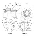
実施の形態1. 以下、この発明の実施の形態1を図1および図2に基づいて説明する。図1はエンジン始動装置の一例を示す縦断正面図である。図2は図1におけるピニオンギア部を示す図であり、(a)は正面図、(b)は右側面図、(c)は(a)図におけるc線部分から図示左向き矢印の方向に見たc視拡大図、(d)は(a)図におけるd線部分から図示左向き矢印の方向に見たd視拡大図である Embodiment 1 FIG. A first embodiment of the present invention will be described below with reference to FIGS. FIG. 1 is a longitudinal front view showing an example of an engine starting device. 2A and 2B are diagrams showing the pinion gear portion in FIG. 1, where FIG. 2A is a front view, FIG. 2B is a right side view, and FIG. 2C is a view from the c line portion in FIG. (D) is a d view enlarged view seen from the d line portion in FIG.
図1に示す本実施の形態1におけるエンジン始動装置は、エンジンを始動させる駆動力を発生するモータ部(以下「モータ駆動力部」と記す)10、出力回転軸20、ピニオンギア部30、吸引コイル部40、プランジャ50、レバー等の押し出し機構(以下「レバー」と記す)60、ブラケット70、ストッパ80(コメント:80は図に表記されていません。本件発明に無関係であれば、この「ストッパ80」は削除したいと思いますが、削除してよいでしょうか?)および減速ギア部90で構成されている。
The engine starter according to the first embodiment shown in FIG. 1 includes a motor unit (hereinafter referred to as “motor drive unit”) 10 that generates a drive force for starting the engine, an
モータ駆動力部10は、エンジンを始動する回転力を発生する。出力回転軸20は、モータの出力軸側と減速ギア部90を介して結合されており、駆動力部10により回転駆動される。ピニオンギア部30は、出力回転軸20とヘリカルスプライン結合されたオーバーランニングクラッチ(一方向クラッチ)と一体化されており、出力回転軸20の軸方向(リングギア等のエンジン始動ギア(以下「リングギア」と記す)の方向)に摺動することができる。
The motor driving
吸引コイル部40は、スイッチ(図示省略)をONすることで電磁力を発生し、当該電磁力によりプランジャ50を吸引する。レバー60は、前記吸引によるプランジャ50の移動によりその枢着軸を中心に回動し、当該回動によりピニオンギア部をそのピニオンギアとエンジン始動ギアとの噛み合い位置の方へ移動させる。ブラケット70は、モータ駆動力部10、出力回転軸20、およびピニオンギア部30等のエンジン始動装置構成部品をエンジン側に固定している。
The
図2に示す本実施の形態1におけるピニオンギア部30は、オーバーランニングクラッチ内蔵の移動体31、筒状の回転部材32、コイルバネ等の弾性部材33、第1のピニオンギア34、第2のピニオンギア35、およびストッパー部36等で構成されている。
The
また、円筒状の回転部材32にはその外周にセレーション部32aが施されている。
第1のピニオンギア34には、その外周にリングギア100と噛合い可能な回転同期用のピニオン歯34aが、その内周に回転部材32のセレーション部32aと嵌め合い可能なセレーション部34bが設けられている。なお、第1のピニオンギア34のピニオン歯34aは、図2(a)(d)に例示のように、先端が突起状である突起歯形状であり、リングギア100と回転同期して噛合し易い形状および軸方向薄さとしてある。
第2のピニオンギア35には、リングギア100と噛合い時の回転同期用且つ回転力伝達用のピニオン歯35aと回転部材32のセレーション部32aと嵌め合い可能なセレーション部35bが設けられている。なお、第2のピニオンギア35のピニオン歯35aは、図2(a)(c)に例示のように、先端が切り取られた非突起歯形状であり、リングギア100が第1のピニオンギア34と噛合した後に第2のピニオンギア35がリングギア100の方向へ移動したとき、リングギア100と回転同期して回転力をリングギア100に伝達する強度を有する形状および軸方向厚さとしてある。
Further, the cylindrical rotating
The
The
第2のピニオンギア35のピニオン歯35aの歯数は、第1のピニオンギア34のピニオン歯34aの歯数と同じである。
The number of teeth of the
回転部材32のセレーション部32aと第1のピニオンギア34のセレーション34bとは軸方向に相対移動可能にセレーション嵌合し第1のセレーション部34abを構成し、回転部材32のセレーション部32aと第2のピニオンギア35のセレーション35bとは軸方向に相対移動可能にセレーション嵌合し第2のセレーション部35abを構成している。
第1のセレーション部34ab歯数は第1のピニオンギア34のピニオン歯34aの歯数の整数倍とし、第2のセレーション部35ab歯数は第2のピニオンギア35のピニオン歯35aの歯数の整数倍としてある。この結果、組立時に第1のピニオンギア34のピニオン歯34aと第2のピニオンギア35のピニオン歯35aの外周方向の位置合わせ、つまり位相合わせを容易に行うことが可能となる。The
The number of teeth of the first serration portion 34ab is an integral multiple of the number of teeth of the
実施の形態2.
以下、この発明の実施の形態2を図3に基づいて説明する。図3はピニオンギア部の他の例を示す図であり、(a)は正面図、(b)は右側面図、(c)は(a)図におけるc線部分から図示左向き矢印の方向に見たc視拡大図、(d)は(a)図におけるd線部分から図示左向き矢印の方向に見たd視拡大図である。 Embodiment 2. FIG.
The second embodiment of the present invention will be described below with reference to FIG. FIGS. 3A and 3B are diagrams showing another example of the pinion gear portion, where FIG. 3A is a front view, FIG. 3B is a right side view, and FIG. 3C is a c-line portion in FIG. FIG. 3D is an enlarged view of the view c, and FIG. 4D is an enlarged view of the view d viewed from the d-line portion in FIG.
図3に示す本実施の形態2におけるピニオンギア部30は、第1ピニオンギア34の内周側に溝部34c、第2のピニオンギア35の内周側に溝部35cがそれぞれ設けられている。
The
この結果、第1および第2のピニオンギア34,35の回転部材32への組立時に溝部34c,35cを重ね合わせることで、第1のピニオンギア34のピニオン歯34aと第2のピニオンギア35のピニオン歯35aの外周方向の位置合わせ、つまり位相合わせを容易に行うことができる。なお、溝部34c,35cを合わせる作業は、人の目視で行っても、また図示しない治工具を使用してもかまわない。
As a result, the
実施の形態3.
また、実施の形態2では溝部34c,35cを用いたが、それぞれのセレーション部34b,35bの1歯を切り欠き、切り欠き部を溝部34c,35cの代わりとしてもよい。 Embodiment 3 FIG.
In the second embodiment, the
実施の形態4.
さらに、セレーション部34b,35bの1歯の歯幅をそれ以外の歯の歯幅と変えて、歯幅の違う1歯を位置合せとして使用しても良い。この時歯幅を広くした場合にはセレーション部32aのセレーションも広くなった1歯に対応して変更する必要がある。 Embodiment 4 FIG.
Further, the tooth width of one tooth of the
実施の形態5.
以下、この発明の実施の形態5を図4に基づいて説明する。図4はピニオンギア部の更に他の例を示す図であり、(a)は正面図、(b)は右側面図、(c)は(a)図におけるcd線部分から図示左向き矢印の方向に見たc視拡大図、(d)は(a)図におけるcd線部分から図示右向き矢印の方向に見たd視拡大図である。Embodiment 5 FIG.
The fifth embodiment of the present invention will be described below with reference to FIG. 4A and 4B are diagrams showing still another example of the pinion gear portion, where FIG. 4A is a front view, FIG. 4B is a right side view, and FIG. 4C is a left arrow direction from the cd line portion in FIG. FIG. 3D is an enlarged view as viewed in c, and FIG. 4D is an enlarged view as viewed in d from the cd line portion in FIG.
図4に示す本実施の形態5におけるピニオンギア部30は、第1ピニオンギア34の第2のピニオンギア35と接する面の一部に凸部34dを有し、第2のピニオンギア35の第1ピニオンギア34と接する面に凸部34dと対向する凹部35dを有している。
The
この結果、第1および第2のピニオンギア34,35の回転部材32への組立時に、凸部34dと凹部35dとを嵌め合わせればよく、第1のピニオンギア34のピニオン歯34aと第2のピニオンギア35のピニオン歯35aの外周方向の位置合わせ、つまり位相合わせを容易に行うことができる。なお、第1ピニオンギア34に凸部34d、第2ピニオンギア35に凹部35dを設けたが、逆に第1ピニオンギア34に凹部を、第2ピニオンギア35に凸部を設けてもよい。
As a result, when the first and second pinion gears 34 and 35 are assembled to the rotating
実施の形態6.
以下、この発明の実施の形態6を図5に基づいて説明する。図5はピニオンギア部の更に他の例を示す正面図である。Embodiment 6 FIG.
A sixth embodiment of the present invention will be described below with reference to FIG. FIG. 5 is a front view showing still another example of the pinion gear portion.
図5に示す本実施の形態6におけるピニオンギア部30は、図示のように、第2のピニオンギア35のリングギア100側の小径の外周面部に、第1のピニオンギア34のリングギア100と反対側の大径の内周面部が、セレーション結合により遊嵌された構造としてあり、第1のピニオンギア34は第2のピニオンギア35に対して周方向及び径方向に所定量移動でき、軸方向にも移動できる構造としてある。
The
第1のピニオンギア34の、第2のピニオンギア35の前記外周面部と対向する前記内周面部に第1ピニオンギア側セレーション部34eが形成され、第2のピニオンギア35の、第1ピニオンギア34の前記内周面部と対向する前記外周面部に第2ピニオンギア側セレーション部35eが形成されている。第1ピニオンギア側セレーション部34eと第2ピニオンギア側セレーション部35eとでピニオンギア間セレーション部345eが構成される。
第1ピニオンギア側セレーション部34eと第2ピニオンギア側セレーション部35eとは遊びがあるように嵌め合わされ、つまり遊嵌され、従って第1のピニオンギア34は第2のピニオンギア35に対して周方向及び径方向に所定量移動でき、軸方向にも移動できる。A first pinion gear
The first pinion gear
第1ピニオンギア側セレーション部34eの歯部の周方向の端面と第2ピニオンギア側セレーション部35eの歯部の周方向の端面との間に所定間隔のギャップを形成することにより周方向の遊びが形成されている。
第1ピニオンギア側セレーション部34eの歯部の径方向の先端面と第2ピニオンギア側セレーション部35eの歯間の谷部の径方向底面との間に所定間隔のギャップを形成すると共に第2ピニオンギア側セレーション部35eの歯部の径方向の先端面と第1ピニオンギア側セレーション部34eの歯間の谷部の径方向底面との間に所定間隔のギャップを形成することにより径方向の遊びが形成されている。By forming a gap of a predetermined interval between the circumferential end surface of the tooth portion of the first pinion gear
A gap having a predetermined interval is formed between the radial tip surface of the tooth portion of the first pinion gear
この結果、第1および第2のピニオンギア34,35の回転部材32への組立時の前段階で、第1のセレーション部34eと35eとを嵌め合わせればよく、第1のピニオンギア34のピニオン歯34aと第2のピニオンギア35のピニオン歯35aの外周方向の位置合わせ、つまり位相合わせを容易に行うことができる。
また、前記遊嵌による前記径方向の遊びにより、第1のピニオンギア34は第2のピニオンギア35に対して傾斜することが可能である。従って、第1のピニオンギア34は、エンジン始動時のリングギア100方向への自身の移動によりリングギア100と衝突した際に傾斜することができ、当該傾斜によりリングギア100と噛合し易くリングギア100との早期噛合が可能となり、ひいては第2のピニオンギア35もリングギア100と噛合し易くリングギア100との早期噛合が可能となる。As a result, the
Further, the
第1のピニオンギア34と第2のピニオンギア35とは分離された別体であることから、第2のピニオンギア35に伝達トルク(エンジン始動装置からエンジン側への回転トルクの伝達、あるいはその逆)に対する強度を持たせ第1のピニオンギア34は噛合い時の伝達トルクに対する強度確保を殆ど無視して噛合いのみを追求した形状、軸方向厚み、質量とすることが可能であり、形状、材料の自由度が高く加工が容易にもなる。
Since the
なお、図1〜図5の各図中、同一符合は同一または相当部分を示す。 In addition, in each figure of FIGS. 1-5, the same code | symbol shows the same or equivalent part.
なお、前述の説明および前述の各図からも明白なように、図1〜図5、本実施の形態1〜6には、以下のような技術的特徴がある。 As is apparent from the above description and the respective drawings, FIGS. 1 to 5 and Embodiments 1 to 6 have the following technical features.
特徴点1:モータ部10、このモータ部10により駆動される出力回転軸20の回転に伴って回転するピニオンギア部30、及び前記ピニオンギア部30をそのピニオンギア34,35とエンジン始動ギア100との噛み合い位置の方へ移動させる押し出し機構60を備え、互いに噛み合った前記ピニオンギア34,35及び前記エンジン始動ギア100を介して前記モータ部10の回転力によりエンジンを始動するエンジン始動装置において、
前記ピニオンギア部30は、前記出力回転軸20の回転に伴って回転する回転部材32と、この回転部材32に第1のセレーション部34abを介して嵌合され前記出力回転軸20の回転に伴って前記回転部材32と共に回転し前記ピニオンギア部30が前記押し出し機構60により前記噛み合い位置の方へ移動させられると前記回転部材32と共に移動して最初に前記エンジン始動ギア100と噛み合う第1のピニオンギア34と、前記回転部材32に前記第1のピニオンギア34に隣接して第2のセレーション部35abを介して嵌合され前記出力回転軸20の回転に伴って前記回転部材32と共に回転し前記ピニオンギア部30が前記押し出し機構60により前記噛み合い位置の方へ更に移動させられると前記回転部材32と共に移動して前記第1のピニオンギア34が前記エンジン始動ギア100と噛み合った状態下で前記第1のピニオンギア34より遅れて前記エンジン始動ギア100と噛み合う第2のピニオンギア35とを有し、
前記第1及び第2のセレーション部34ab,35abにより前記第1のピニオンギア34の歯34aと前記第2のピニオンギア35の歯35aとの周方向の位相が合うように前記嵌合が行われる。 Characteristic 1: The
The
The fitting is performed by the first and second serration portions 34ab and 35ab so that the circumferential phases of the
特徴点2:特徴点1に記載のエンジン始動装置において、
前記第1のピニオンギア34の歯34aは先端が突起状である突起歯形状であり、前記第2のピニオンギア35の歯35aは非突起歯形状である。 Feature point 2: In the engine starter described in feature point 1,
The
特徴点3:特徴点1または特徴点2に記載のエンジン始動装置において、
前記第1のピニオンギア34の前記エンジン始動ギア100の方向の厚さが、前記第2のピニオンギア35の前記エンジン始動ギア100の方向の厚さより薄い。 Feature point 3: In the engine starting device described in feature point 1 or feature point 2,
The thickness of the
特徴点4:特徴点1〜特徴点3の何れか一に記載のエンジン始動装置において、
前記第1のピニオンギア34は前記エンジン始動ギア100との回転同期をとる機能を有し、
前記第2のピニオンギア35は前記エンジン始動ギア100との噛み合いにより前記第2のピニオンギア35の回転力を前記エンジン始動ギア100に伝達する機能を有している。 Feature point 4: In the engine starting device according to any one of feature points 1 to 3,
The
The
特徴点5:特徴点1〜特徴点4の何れか一に記載のエンジン始動装置において、
前記第1のセレーション部34abと前記第2のセレーション部35abとに跨って位置合わせ機構60部が設けられ、
前記第1及び第2のセレーション部35abとに跨って設けられた前記位置合わせ構造部により前記第1のピニオンギア34の歯34aと前記第2のピニオンギア35の歯35aとの周方向の位相が合うように前記嵌合が行われる。 Feature point 5: In the engine starting device according to any one of feature points 1 to 4,
An
The phase in the circumferential direction between the
特徴点6:特徴点1〜特徴点5の何れか一に記載のエンジン始動装置において、
前記第1のセレーション部34abの歯数が前記第1のピニオンギア34の歯数の整数倍であり、前記第2のセレーション部35abの歯数が前記第2のピニオンギア35の歯数の整数倍である。 Feature point 6: In the engine starting device according to any one of feature points 1 to 5,
The number of teeth of the first serration portion 34ab is an integral multiple of the number of teeth of the
特徴点7:特徴点6に記載のエンジン始動装置において、
前記第1のセレーション部34abの歯数と前記第2のセレーション部35abの歯数とが同じである。Feature point 7: In the engine starter described in feature point 6,
The number of teeth of the first serration portion 34ab and the number of teeth of the second serration portion 35ab are the same.
特徴点8:特徴点5〜特徴点7の何れか一に記載のエンジン始動装置において、
前記位置合わせ構造部が、前記第1及び第2のセレーション部34ab,35abとに跨って設けられた溝であり、
前記第1のセレーション部34ab側の前記溝と第2のセレーション部35ab側の前記溝とを重ね合わせることにより前記第1のピニオンギア34の歯34aと前記第2のピニオンギア35の歯35aとの周方向の位相が合うように前記嵌合が行われる。 Feature point 8: In the engine starting device according to any one of feature points 5 to 7,
The alignment structure portion is a groove provided across the first and second serration portions 34ab, 35ab;
By overlapping the groove on the first serration portion 34ab side and the groove on the second serration portion 35ab side, the
特徴点9:特徴点5〜特徴点7の何れか一に記載のエンジン始動装置において、
前記位置合わせ構造部が、前記第1および第2のピニオンギア34,35に跨って前記第1及び第2のセレーション部34ab,35abの少なくとも一つの歯を切り欠いて形成され、
前記第1のセレーション部34ab側の前記切りかかれた歯と第2のセレーション部35ab側の前記切りかかれた歯とを重ね合わせることにより前記第1のピニオンギア34の歯34aと前記第2のピニオンギア35の歯35aとの周方向の位相が合うように前記嵌合が行われる。 Feature point 9: In the engine starting device according to any one of feature points 5 to 7,
The alignment structure portion is formed by cutting out at least one tooth of the first and second serration portions 34ab, 35ab across the first and second pinion gears 34, 35;
The
特徴点10:特徴点5〜特徴点7の何れか一に記載のエンジン始動装置において、
前記位置合わせ構造部が、前記第1および第2のピニオンに跨って前記第1及び第2のセレーション部34ab,35abの少なくとも一つの歯の幅が他の歯の幅より広く構成して形成され、
前記第1のセレーション部34ab側の前記幅広の歯と第2のセレーション部35ab側の前記幅広の歯とを重ね合わせることにより前記第1のピニオンギア34の歯34aと前記第2のピニオンギア35の歯35aとの周方向の位相が合うように前記嵌合が行われる。Feature point 10: In the engine starting device according to any one of feature points 5 to 7,
The alignment structure portion is formed so that the width of at least one tooth of the first and second serration portions 34ab, 35ab is wider than the width of the other teeth across the first and second pinions. ,
The
特徴点11:特徴点5〜特徴点7の何れか一に記載のエンジン始動装置において、
前記位置合わせ構造部が、前記第1のピニオンギア34と前記第2ピニオンギア35との対向面の一方に凸部34dを、他方に凹部35dを設けて形成され、
前記凸部34dと前記凹部35dとを嵌め合わせることにより前記第1のピニオンギア34の歯34aと前記第2のピニオンギア35の歯35aとの周方向の位相が合うように前記嵌合が行われる。 Feature point 11: In the engine starting device according to any one of feature points 5 to 7,
The alignment structure portion is formed by providing a
The fitting is performed so that the circumferential phases of the
特徴点12:特徴点1〜特徴点11に記載のエンジン始動装置において、
前記回転部材32の前記エンジン始動ギア100側の端部に、前記第1のピニオンギア34と前記第2ピニオンギア35の前記エンジン始動ギア100の方向への移動を規制するストッパ部36が設けられ、
前記回転部材32の前記第1及び第2のピニオンギア35を挟んで前記ストッパ部36とは反対の側に弾性部材33が配設され、
前記第1及び第2のピニオンギア34,35が前記弾性部材33により前記ストッパ部36側へ押圧付勢されている。 Feature point 12: In the engine starting device described in feature point 1 to feature point 11,
A
An
The first and second pinion gears 34 and 35 are pressed and urged toward the
特徴点13: モータ部10、このモータ部10により駆動される出力回転軸20の回転に伴って回転するピニオンギア部30、及び前記ピニオンギア部30をそのピニオンギア34,35とエンジン始動ギア100との噛み合い位置の方へ移動させる押し出し機構60を備え、互いに噛み合った前記ピニオンギア34,35及び前記エンジン始動ギア100を介して前記モータ部10の回転力によりエンジンを始動するエンジン始動装置において、
前記ピニオンギア部30は、前記出力回転軸20の回転に伴って回転する回転部材32と、前記出力回転軸20の回転に伴って前記回転部材32と共に回転し前記ピニオンギア部30が前記押し出し機構60により前記噛み合い位置の方へ移動させられると前記回転部材32と共に移動して最初に前記エンジン始動ギア100と噛み合う第1のピニオンギア34と、前記回転部材32に前記第1のピニオンギア34に隣接してセレーション部を介して嵌合され前記出力回転軸20の回転に伴って前記回転部材32と共に回転し前記ピニオンギア部30が前記押し出し機構60により前記噛み合い位置の方へ更に移動させられると前記回転部材32と共に移動して前記第1のピニオンギア34が前記エンジン始動ギア100と噛み合った状態下で前記第1のピニオンギア34より遅れて前記エンジン始動ギア100と噛み合う第2のピニオンギア35を有し、
前記第1のピニオンギア34は、前記第2のピニオンギア35に、両ピニオンギア34,35間に形成されたピニオンギア間セレーション部を介して嵌合し、前記ピニオンギア間セレーション部により前記第1のピニオンギア34の歯34aと前記第2のピニオンギア35の歯35aとの周方向の位相が合うように前記嵌合が行われる。Characteristic 13: The
The
The
特徴点14: 特徴点1〜特徴点13の何れか一に記載のエンジン始動装置において、
前記第1のピニオンギア34が前記第2のピニオンギア35に対して傾斜できるように前記第1のピニオンギア34の前記嵌合の状態が遊嵌の状態である。Feature point 14: In the engine starting device according to any one of feature points 1 to 13,
The fitting state of the
特徴点15: スタータモータ10と、前記スタータモータ10の出力軸20側にスプライン結合された軸方向に摺動する移動体31と、移動体31の一部を構成する円筒状回転部材32に相対回転不能に取り付けられたピニオンギア部30と、ピニオンギア部30をリングギアとの噛み合い位置に移動させる押し出し機構60を有し、前記押し出し機構60により押し出された前記ピニオンギア部30のピニオンと噛み合い、前記スタータモータの回転力が伝達されることでエンジンを始動するリングギアとを備え、前記ピニオンギア部30は、同期用の突起歯形状を有し、前記リングギアとの噛み合い開始時に前記リングギアと最初に衝突する第1のピニオンギア34と、噛み合い後に回転力を伝達する役目を果たす第2のピニオンギア35とで構成されるエンジン始動装置において、第1のピニオンおよび第2のピニオンはいずれも、各々の内径の施されたセレーション部と、前記円筒状回転部材32の外周に施されたセレーション部によりセレーション嵌合される。
Feature 15: Relative to the
特徴点16: 特徴点15に記載のエンジン始動装置において、セレーション部34ab,35abの歯数がピニオン34,35の歯数の整数倍である。
Feature point 16: In the engine starting device described in the
特徴点17: 特徴点15に記載のエンジン始動装置において、第1および第2のピニオン34,35の内径に位置合わせ部として溝部34c,35cを設けた。
Characteristic point 17: In the engine starter described in the
特徴点18: 特徴点15に記載のエンジン始動装置において、第1および第2のピニオン34,35の内径に設けられたセレーション部34b,35bの少なくとも一歯を切り欠いて位置合わせ部とした。
Feature point 18: In the engine starter described in the
特徴点19: 特徴点15に記載のエンジン始動装置において、前記円筒状回転部材32のセレーションの少なくとも1歯が他よりも幅が広く構成され、第1および第2のピニオン34,35の内径のセレーション34b,35bも円筒状回転部材32のセレーション32aに対応して少なくとも1箇所の幅が異なることにより位置合わせ部とした。
Characteristic point 19: In the engine starting device described in the
特徴点20: 特徴点16〜特徴点19の何れか一に記載のエンジン始動装置において、予め第1および第2のピニオン34,35の内径に設けられた位置合わせ部により第1のピニオン34と第2のピニオン35の位置を合わせて、前記円筒状回転部材32に組み付ける。
Feature point 20: In the engine starting device according to any one of the feature point 16 to the feature point 19, the
特徴点21: スタータモータ10と、前記スタータモータ10の出力軸20側にスプライン結合された軸方向に摺動する移動体31と、移動体31の一部を構成する円筒状回転部材32に相対回転不能に取り付けられたピニオンギア部30と、ピニオンギア部30をリングギアとの噛み合い位置に移動させる押し出し機構60を有し、前記押し出し機構60により押し出された前記ピニオンギア部30のピニオン34,35と噛み合い、前記スタータモータ10の回転力が伝達されることでエンジンを始動するリングギア100とを備え、前記ピニオンギア部30は、同期用の突起歯形状を有し、前記リングギア100との噛み合い開始時に前記リングギア100と最初に衝突する第1のピニオンギア34と、噛み合い後に回転力を伝達する役目を果たす第2のピニオンギア35とで構成されるエンジン始動装置において、第1のピニオンギア34は前記円筒状回転部材32に形成されたセレーション部32aにセレーション嵌合し、第1のピニオンギア34は、第2のピニオン35に設けられた位置決め部35dと嵌合される。
Feature 21: Relative to the
特徴点22: 特徴点21に記載のエンジン始動装置において、第2のピニオンギア35は前記円筒状回転部材32に形成されたセレーション部32aにセレーション嵌合し、第1のピニオンギアの第2ピニオンギア35との当接面に設けられた凸部34d(或いは凹部)が、第2のピニオンギア35の第1ピニオンギア34との当接面に設けられた凹部35d(或いは凸部)に嵌合することで位置決めされる。
Feature point 22: In the engine starting device described in the feature point 21, the
特徴点23: 特徴点15〜特徴点22の何れか一に記載のエンジン始動装置において、移動体31の一部を構成する円筒状回転部材32にはピニオンギア部30の軸方向の移動を規制するストッパ部36と、ピニオンギア部30を挟んでストッパ36とは反対側には、バネなどの弾性部材33を備え、第1のピニオンギア34および、第2のピニオンギア35は、前記弾性部材33により、ストッパ36側へ押圧付勢されている。
Feature point 23: In the engine starting device according to any one of the
特徴点24:スタータモータ10と、スタータモータ10の出力軸20側にスプライン結合された軸方向に摺動するピニオンギア部30と、キースイッチがONされることで吸引されるプランジャ50の移動に伴って、オーバーランニングクラッチおよびピニオン30,34,35をエンジンのリングギア100方向に押し出すシフトレバー60と、シフトレバー60により押し出されたピニオン34,35と噛み合い、スタータモータ10の回転力が伝達されることでエンジンを始動するリングギア100とを備えたエンジン始動装置において、ピニオン30は、同期用の歯形状を有し、リングギアとの噛み合い開始時にリングギアと最初に衝突する第1ピニオンギア34と、噛み合い後に回転力を伝達する役目を果たす第2ピニオンギア35とに、軸方向で2分割されたピニオンギアを有する。
さらに第1のピニオンギア34および第2のピニオンギア35はいずれも、各々の内径に施されたセレーション部34b,35bと、スタータモータの出力軸側にスプライン結合された軸方向に摺動する移動体31の円筒状回転部材32の外周に施されたセレーション部32aによりセレーション嵌合されるとき、円筒状回転部材32の外周に施されたセレーション32aや第1のピニオンギア34および第2のピニオンギア35の内径の施されたセレーション34ab,35abの歯数が第1のピニオンギア34のピニオン歯数および第2のピニオンギア35の突起部の歯数の整数倍で構成されているピニオンギア部30を有する。
また、第1のピニオンギア34のピニオン歯と第2のピニオンギア35の突起部の位置合せが容易に行える機能を有している。Feature 24: The
Further, both the
Further, the
Claims (14)
前記ピニオンギア部は、前記出力回転軸の回転に伴って回転する回転部材と、この回転部材に第1のセレーション部を介して嵌合され前記出力回転軸の回転に伴って前記回転部材と共に回転し前記ピニオンギア部が前記押し出し機構により前記噛み合い位置の方へ移動させられると前記回転部材と共に移動して最初に前記エンジン始動ギアと噛み合う第1のピニオンギアと、前記回転部材に前記第1のピニオンギアに隣接して第2のセレーション部を介して嵌合され前記出力回転軸の回転に伴って前記回転部材と共に回転し前記ピニオンギア部が前記押し出し機構により前記噛み合い位置の方へ更に移動させられると前記回転部材と共に移動して前記第1のピニオンギアが前記エンジン始動ギアと噛み合った状態下で前記第1のピニオンギアより遅れて前記エンジン始動ギアと噛み合う第2のピニオンギアとを有し、
前記第1および第2のセレーション部により前記第1のピニオンギアの歯と前記第2のピニオンギアの歯との周方向の位相が合うように前記嵌合が行われる
ことを特徴とするエンジン始動装置。 A motor unit, a pinion gear unit that rotates as the output rotation shaft driven by the motor unit rotates, and an extrusion mechanism that moves the pinion gear unit toward the meshing position of the pinion gear and the engine start gear In the engine starting device for starting the engine by the rotational force of the motor unit via the pinion gear and the engine starting gear engaged with each other,
The pinion gear portion is rotated with the rotation of the output rotation shaft, and is fitted to the rotation member via a first serration portion, and rotates together with the rotation member with the rotation of the output rotation shaft. When the pinion gear portion is moved toward the meshing position by the push-out mechanism, the first pinion gear that moves together with the rotating member and first meshes with the engine starting gear, and the first member on the rotating member. It is fitted through a second serration portion adjacent to the pinion gear, and rotates together with the rotating member as the output rotation shaft rotates, and the pinion gear portion is further moved toward the meshing position by the push-out mechanism. When the first pinion gear is moved together with the rotating member and the first pinion gear meshes with the engine start gear, Ri delay and a second pinion gear meshing with the engine starting gear,
The engine start is characterized in that the first and second serration portions perform the fitting so that the circumferential phases of the teeth of the first pinion gear and the teeth of the second pinion gear are matched. apparatus.
前記第1のピニオンギアの歯は先端が突起状である突起歯形状であり、前記第2のピニオンギアの歯は非突起歯形状である
ことを特徴とするエンジン始動装置。 The engine starter according to claim 1,
The engine starter characterized in that the teeth of the first pinion gear have a protruding tooth shape with a protruding end, and the teeth of the second pinion gear have a non-projecting tooth shape.
前記第1のピニオンギアの前記エンジン始動ギアの方向の厚さが、前記第2のピニオンギアの前記エンジン始動ギアの方向の厚さより薄い
ことを特徴とするエンジン始動装置。 The engine starting device according to claim 1 or 2,
The engine starter characterized in that the thickness of the first pinion gear in the direction of the engine starter gear is thinner than the thickness of the second pinion gear in the direction of the engine starter gear.
前記第1のピニオンギアは前記エンジン始動ギアとの回転同期をとる機能を有し、
前記第2のピニオンギアは前記エンジン始動ギアとの噛み合いにより前記第2のピニオンギアの回転力を前記エンジン始動ギアに伝達する機能を有している
ことを特徴とするエンジン始動装置。 In the engine starting device according to any one of claims 1 to 3,
The first pinion gear has a function of synchronizing rotation with the engine start gear,
The engine starter characterized in that the second pinion gear has a function of transmitting the rotational force of the second pinion gear to the engine start gear by meshing with the engine start gear.
前記第1のセレーション部と前記第2のセレーション部とに跨って位置合わせ構造部が設けられ、
前記第1および第2のセレーション部とに跨って設けられた前記位置合わせ構造部により前記第1のピニオンギアの歯と前記第2のピニオンギアの歯との周方向の位相が合うように前記嵌合が行われる
ことを特徴とするエンジン始動装置。 In the engine starting device according to any one of claims 1 to 4,
An alignment structure portion is provided across the first serration portion and the second serration portion,
The alignment structure portion provided across the first and second serration portions so that the phase in the circumferential direction of the teeth of the first pinion gear and the teeth of the second pinion gear is matched. An engine starter characterized in that fitting is performed.
前記第1のセレーション部の歯数が前記第1のピニオンギアの歯数の整数倍であり、前記第2のセレーション部の歯数が前記第2のピニオンギアの歯数の整数倍である
ことを特徴とするエンジン始動装置。 In the engine starting device according to any one of claims 1 to 5,
The number of teeth of the first serration unit is an integer multiple of the number of teeth of the first pinion gear, and the number of teeth of the second serration unit is an integer multiple of the number of teeth of the second pinion gear. An engine starter characterized by.
前記第1のセレーション部の歯数と前記第2のセレーション部の歯数とが同じである
ことを特徴とするエンジン始動装置。 The engine starter according to claim 6, wherein
The engine starter characterized in that the number of teeth of the first serration portion and the number of teeth of the second serration portion are the same.
前記第1のセレーション部と前記第2のセレーション部とに跨って設けられた位置合わせ構造部が、前記第1および第2のセレーション部とに跨って設けられた溝であり、
前記第1のセレーション部側の前記溝と第2のセレーション部側の前記溝とを重ね合わせることにより前記第1のピニオンギアの歯と前記第2のピニオンギアの歯との周方向の位相が合うように前記嵌合が行われる
ことを特徴とするエンジン始動装置。 The engine starter according to any one of claims 5 to 7,
The alignment structure portion provided across the first serration portion and the second serration portion is a groove provided across the first and second serration portions,
By overlapping the groove on the first serration portion side with the groove on the second serration portion side, the circumferential phase between the teeth of the first pinion gear and the teeth of the second pinion gear is increased. The engine starting device is characterized in that the fitting is performed to fit.
前記第1のセレーション部と前記第2のセレーション部とに跨って設けられた位置合わせ構造部が、前記第1および第2のピニオンに跨って前記第1および第2のセレーション部の少なくとも一つの歯を切り欠いて形成され、
前記第1のセレーション部側の前記切りかかれた歯と第2のセレーション部側の前記切りかかれた歯とを重ね合わせることにより前記第1のピニオンギアの歯と前記第2のピニオンギアの歯との周方向の位相が合うように前記嵌合が行われる
ことを特徴とするエンジン始動装置。 The engine starter according to any one of claims 5 to 7,
The alignment structure portion provided across the first serration portion and the second serration portion is at least one of the first and second serration portions across the first and second pinions. Formed by cutting out teeth,
The teeth of the first pinion gear and the teeth of the second pinion gear are formed by superimposing the cut teeth on the first serration portion side and the cut teeth on the second serration portion side. The engine starting device is characterized in that the fitting is performed so that the phases in the circumferential direction are matched.
前記第1のセレーション部と前記第2のセレーション部とに跨って設けられた位置合わせ構造部が、前記第1および第2のピニオンに跨って前記第1および第2のセレーション部の少なくとも一つの歯の幅が他の歯の幅より広い幅広に構成して形成され、
前記第1のセレーション部側の前記幅広の歯と第2のセレーション部側の前記幅広の歯とを重ね合わせることにより前記第1のピニオンギアの歯と前記第2のピニオンギアの歯との周方向の位相が合うように前記嵌合が行われる
ことを特徴とするエンジン始動装置。 The engine starter according to any one of claims 5 to 7,
The alignment structure portion provided across the first serration portion and the second serration portion is at least one of the first and second serration portions across the first and second pinions. The width of the teeth is configured to be wider than the width of the other teeth,
A circumference of the first pinion gear teeth and the second pinion gear teeth by overlapping the wide teeth on the first serration portion side and the wide teeth on the second serration portion side. The engine starting device is characterized in that the fitting is performed so that the phases of the directions are matched.
前記第1のセレーション部と前記第2のセレーション部とに跨って設けられた位置合わせ構造部が、前記第1のピニオンギアと前記第2ピニオンギアとの対向面の一方に凸部を、他方に凹部を設けて形成され、
前記凸部と前記凹部とを嵌め合わせることにより前記第1のピニオンギアの歯と前記第2のピニオンギアの歯との周方向の位相が合うように前記嵌合が行われる
ことを特徴とするエンジン始動装置。 The engine starter according to any one of claims 5 to 7,
The alignment structure portion provided across the first serration portion and the second serration portion has a convex portion on one of the opposing surfaces of the first pinion gear and the second pinion gear, and the other Formed with a recess,
The fitting is performed so that the phases of the teeth of the first pinion gear and the teeth of the second pinion gear match each other by fitting the protrusions and the recesses. Engine starter.
前記回転部材の前記エンジン始動ギアの側の端部に、前記第1のピニオンギアと前記第2ピニオンギアの前記エンジン始動ギアの方向への移動を規制するストッパ部が設けられ、
前記回転部材の前記第1および第2のピニオンギアを挟んで前記ストッパ部とは反対の側に弾性部材が配設され、
前記第1および第2のピニオンギアが前記弾性部材により前記ストッパ部の側へ押圧付勢されている
ことを特徴とするエンジン始動装置。 In the engine starting device according to any one of claims 1 to 11,
A stopper portion for restricting movement of the first pinion gear and the second pinion gear in the direction of the engine start gear is provided at an end of the rotating member on the engine start gear side,
An elastic member is disposed on the opposite side of the stopper portion across the first and second pinion gears of the rotating member,
The engine starting device, wherein the first and second pinion gears are pressed and urged toward the stopper portion by the elastic member.
前記ピニオンギア部は、前記出力回転軸の回転に伴って回転する回転部材と、前記出力回転軸の回転に伴って前記回転部材と共に回転し前記ピニオンギア部が前記押し出し機構により前記噛み合い位置の方へ移動させられると前記回転部材と共に移動して最初に前記エンジン始動ギアと噛み合う第1のピニオンギアと、前記回転部材に前記第1のピニオンギアに隣接してセレーション部を介して嵌合され前記出力回転軸の回転に伴って前記回転部材と共に回転し前記ピニオンギア部が前記押し出し機構により前記噛み合い位置の方へ更に移動させられると前記回転部材と共に移動して前記第1のピニオンギアが前記エンジン始動ギアと噛み合った状態下で前記第1のピニオンギアより遅れて前記エンジン始動ギアと噛み合う第2のピニオンギアを有し、
前記第1のピニオンギアは、前記第2のピニオンギアに、前記第1のピニオンギアと前記第2のピニオンギアとの間に形成されたピニオンギア間セレーション部を介して嵌合し、前記ピニオンギア間セレーション部により前記第1のピニオンギアの歯と前記第2のピニオンギアの歯との周方向の位相が合うように前記嵌合が行われる
ことを特徴とするエンジン始動装置。 A motor unit, a pinion gear unit that rotates as the output rotation shaft driven by the motor unit rotates, and an extrusion mechanism that moves the pinion gear unit toward the meshing position of the pinion gear and the engine start gear In the engine starting device for starting the engine by the rotational force of the motor unit via the pinion gear and the engine starting gear engaged with each other,
The pinion gear portion rotates with the rotation of the output rotation shaft, and rotates together with the rotation member with the rotation of the output rotation shaft. The pinion gear portion moves toward the meshing position by the push-out mechanism. The first pinion gear that moves together with the rotating member and first meshes with the engine start gear, and is fitted to the rotating member via the serration portion adjacent to the first pinion gear. When the output rotating shaft rotates, the pinion gear portion rotates together with the rotating member, and when the pinion gear portion is further moved toward the meshing position by the push-out mechanism, the first pinion gear moves together with the rotating member. A second pinion gear that meshes with the engine start gear later than the first pinion gear in a state of meshing with the start gear. Have,
The first pinion gear is engaged with the second pinion gear via a serration portion between pinion gears formed between the first pinion gear and the second pinion gear, and the pinion The engine starter is characterized in that the fitting is performed by the inter-gear serration portion so that the circumferential phases of the teeth of the first pinion gear and the teeth of the second pinion gear are matched.
前記第1のピニオンギアが前記第2のピニオンギアに対して傾斜できるように前記第1のピニオンギアの前記嵌合の状態が遊嵌の状態である
ことを特徴とするエンジン始動装置。 In the engine starting device according to any one of claims 1 to 13,
The engine starter according to claim 1, wherein the fitting state of the first pinion gear is a loose fitting state so that the first pinion gear can be inclined with respect to the second pinion gear.
Applications Claiming Priority (1)
| Application Number | Priority Date | Filing Date | Title |
|---|---|---|---|
| PCT/JP2011/058211 WO2012131975A1 (en) | 2011-03-31 | 2011-03-31 | Engine starting device |
Publications (2)
| Publication Number | Publication Date |
|---|---|
| JP5444503B2 true JP5444503B2 (en) | 2014-03-19 |
| JPWO2012131975A1 JPWO2012131975A1 (en) | 2014-07-24 |
Family
ID=46929796
Family Applications (1)
| Application Number | Title | Priority Date | Filing Date |
|---|---|---|---|
| JP2013506983A Expired - Fee Related JP5444503B2 (en) | 2011-03-31 | 2011-03-31 | Engine starter |
Country Status (6)
| Country | Link |
|---|---|
| US (1) | US9175657B2 (en) |
| EP (1) | EP2693044A4 (en) |
| JP (1) | JP5444503B2 (en) |
| KR (1) | KR101488128B1 (en) |
| CN (1) | CN103459830B (en) |
| WO (1) | WO2012131975A1 (en) |
Families Citing this family (5)
| Publication number | Priority date | Publication date | Assignee | Title |
|---|---|---|---|---|
| JP5804742B2 (en) * | 2010-08-20 | 2015-11-04 | 三菱電機株式会社 | Engine starter |
| DE102011017534B4 (en) * | 2011-04-26 | 2020-06-04 | Seg Automotive Germany Gmbh | Starting device for an internal combustion engine |
| JP6012793B2 (en) * | 2015-03-03 | 2016-10-25 | 三菱電機株式会社 | Engine starter |
| DE102015219505B4 (en) | 2015-10-08 | 2019-03-07 | Bayerische Motoren Werke Aktiengesellschaft | Pinion starter gearbox with corrected gear geometry |
| JP7291462B2 (en) * | 2018-04-19 | 2023-06-15 | 株式会社シマノ | Rotation detection device and rotation driving force detection system |
Family Cites Families (33)
| Publication number | Priority date | Publication date | Assignee | Title |
|---|---|---|---|---|
| US1348288A (en) * | 1919-03-31 | 1920-08-03 | Eclipse Machine Co | Engine-starter |
| US2423068A (en) * | 1945-08-02 | 1947-06-24 | Bendix Aviat Corp | Engine starter |
| US4488054A (en) * | 1982-04-13 | 1984-12-11 | Hitachi, Ltd. | Starter apparatus |
| US5046373A (en) * | 1989-08-07 | 1991-09-10 | Briggs & Stratton Corp. | Starter motor construction |
| JPH0792035B2 (en) * | 1990-06-08 | 1995-10-09 | 三菱電機株式会社 | Starter motor with intermediate gear |
| JPH0710606U (en) | 1993-07-15 | 1995-02-14 | ダイハツ工業株式会社 | Scissors gear |
| JP3578184B2 (en) * | 1995-05-19 | 2004-10-20 | 株式会社デンソー | Starter |
| US5767585A (en) * | 1993-12-27 | 1998-06-16 | Nippondenso Co., Ltd. | Starter |
| JP3562072B2 (en) * | 1994-11-29 | 2004-09-08 | 株式会社デンソー | Starter |
| DE69704234T2 (en) * | 1996-07-10 | 2001-10-25 | Denso Corp | Starter with a control device for the pinion movement |
| JP3722639B2 (en) * | 1999-03-25 | 2005-11-30 | 三菱自動車工業株式会社 | Starter for internal combustion engine |
| JP4211208B2 (en) | 2000-08-23 | 2009-01-21 | トヨタ自動車株式会社 | Fuel consumption saving car |
| JP2002303236A (en) * | 2001-04-02 | 2002-10-18 | Denso Corp | Starter |
| JP3823841B2 (en) * | 2002-02-15 | 2006-09-20 | 株式会社デンソー | Starter with intermediate gear |
| US20040079179A1 (en) * | 2002-10-23 | 2004-04-29 | Bombardier-Rotax Gmbh & Co. K.G. | Slip clutch for starter drive |
| JP4155115B2 (en) * | 2003-06-10 | 2008-09-24 | 株式会社デンソー | Starter |
| CN101044316A (en) * | 2004-10-20 | 2007-09-26 | 株式会社美姿把 | Starter motor with idle gear |
| JP4238816B2 (en) | 2004-11-02 | 2009-03-18 | トヨタ自動車株式会社 | Starter for internal combustion engine and starter gear unit provided in the starter |
| JP4020209B2 (en) * | 2005-01-14 | 2007-12-12 | 三菱電機株式会社 | Starter motor with intermediate gear |
| JP4375314B2 (en) * | 2005-09-26 | 2009-12-02 | 株式会社デンソー | Starter |
| JP4552924B2 (en) * | 2006-11-02 | 2010-09-29 | 株式会社デンソー | Starter |
| JP2009024665A (en) * | 2007-07-23 | 2009-02-05 | Toyota Central R&D Labs Inc | Engine starting device |
| EP2080898B1 (en) * | 2008-01-18 | 2020-03-11 | Denso Corporation | Starter with compact structure |
| JP5212065B2 (en) * | 2008-01-18 | 2013-06-19 | 株式会社デンソー | Starter |
| JP2009168230A (en) | 2008-01-21 | 2009-07-30 | Denso Corp | Pinion and starter using the same |
| EP2151573B1 (en) | 2008-08-07 | 2015-04-15 | Denso Corporation | A starting device for combustion engines |
| DE102008054965B4 (en) * | 2008-12-19 | 2018-08-23 | Seg Automotive Germany Gmbh | Method and device for start-stop systems of internal combustion engines in motor vehicles |
| JP5272879B2 (en) * | 2009-04-28 | 2013-08-28 | 株式会社デンソー | Starter |
| DE102009026593A1 (en) * | 2009-05-29 | 2010-12-02 | Robert Bosch Gmbh | Method for the mechanical synchronization of two rotating, off-axis spur gears |
| US8408175B2 (en) * | 2010-08-03 | 2013-04-02 | GM Global Technology Operations LLC | Stop-start self-synchronizing starter system |
| JP5804742B2 (en) * | 2010-08-20 | 2015-11-04 | 三菱電機株式会社 | Engine starter |
| WO2012131973A1 (en) | 2011-03-31 | 2012-10-04 | 三菱電機株式会社 | Engine starting device |
| CN103459829B (en) | 2011-03-31 | 2016-01-27 | 三菱电机株式会社 | Engine starting gear |
-
2011
- 2011-03-31 KR KR1020137026526A patent/KR101488128B1/en active IP Right Grant
- 2011-03-31 US US13/977,869 patent/US9175657B2/en not_active Expired - Fee Related
- 2011-03-31 CN CN201180069768.9A patent/CN103459830B/en not_active Expired - Fee Related
- 2011-03-31 JP JP2013506983A patent/JP5444503B2/en not_active Expired - Fee Related
- 2011-03-31 WO PCT/JP2011/058211 patent/WO2012131975A1/en active Application Filing
- 2011-03-31 EP EP11862741.3A patent/EP2693044A4/en not_active Withdrawn
Also Published As
| Publication number | Publication date |
|---|---|
| EP2693044A1 (en) | 2014-02-05 |
| US9175657B2 (en) | 2015-11-03 |
| CN103459830B (en) | 2016-03-16 |
| JPWO2012131975A1 (en) | 2014-07-24 |
| WO2012131975A1 (en) | 2012-10-04 |
| CN103459830A (en) | 2013-12-18 |
| US20130291681A1 (en) | 2013-11-07 |
| KR101488128B1 (en) | 2015-01-29 |
| EP2693044A4 (en) | 2014-09-03 |
| KR20140000330A (en) | 2014-01-02 |
Similar Documents
| Publication | Publication Date | Title |
|---|---|---|
| WO2012077501A1 (en) | Engine starting device | |
| JP5762371B2 (en) | Engine starter | |
| JP5444503B2 (en) | Engine starter | |
| JP5804742B2 (en) | Engine starter | |
| JP5322132B2 (en) | Method and apparatus for an internal combustion engine start-stop device in a motor vehicle | |
| JP6012788B2 (en) | Engine starter | |
| JP5632679B2 (en) | Synchronizer and transmission including the same | |
| KR101501868B1 (en) | Engine starting device | |
| WO2012131974A1 (en) | Engine starting apparatus | |
| JP2012041881A (en) | Engine starting device | |
| US9683534B2 (en) | Starter and engaging device thereof | |
| JP2009156327A (en) | Transmission for vehicle | |
| KR101321614B1 (en) | Synchronizer for manual transmission | |
| JP5955362B2 (en) | Engine starter | |
| JP5966844B2 (en) | Starter | |
| JP2014224489A5 (en) | ||
| JP2014224489A (en) | Engine starter | |
| JP2009068551A (en) | Transmission | |
| JP2017106550A (en) | Power transmission device for vehicle |
Legal Events
| Date | Code | Title | Description |
|---|---|---|---|
| TRDD | Decision of grant or rejection written | ||
| A01 | Written decision to grant a patent or to grant a registration (utility model) |
Free format text: JAPANESE INTERMEDIATE CODE: A01 Effective date: 20131210 |
|
| A61 | First payment of annual fees (during grant procedure) |
Free format text: JAPANESE INTERMEDIATE CODE: A61 Effective date: 20131220 |
|
| R151 | Written notification of patent or utility model registration |
Ref document number: 5444503 Country of ref document: JP Free format text: JAPANESE INTERMEDIATE CODE: R151 |
|
| R250 | Receipt of annual fees |
Free format text: JAPANESE INTERMEDIATE CODE: R250 |
|
| R250 | Receipt of annual fees |
Free format text: JAPANESE INTERMEDIATE CODE: R250 |
|
| R250 | Receipt of annual fees |
Free format text: JAPANESE INTERMEDIATE CODE: R250 |
|
| LAPS | Cancellation because of no payment of annual fees |