JP5444086B2 - Electromagnetic flow meter - Google Patents
Electromagnetic flow meter Download PDFInfo
- Publication number
- JP5444086B2 JP5444086B2 JP2010079353A JP2010079353A JP5444086B2 JP 5444086 B2 JP5444086 B2 JP 5444086B2 JP 2010079353 A JP2010079353 A JP 2010079353A JP 2010079353 A JP2010079353 A JP 2010079353A JP 5444086 B2 JP5444086 B2 JP 5444086B2
- Authority
- JP
- Japan
- Prior art keywords
- period
- excitation
- signal
- value
- electrodes
- Prior art date
- Legal status (The legal status is an assumption and is not a legal conclusion. Google has not performed a legal analysis and makes no representation as to the accuracy of the status listed.)
- Active
Links
Images


Classifications
-
- G—PHYSICS
- G01—MEASURING; TESTING
- G01F—MEASURING VOLUME, VOLUME FLOW, MASS FLOW OR LIQUID LEVEL; METERING BY VOLUME
- G01F1/00—Measuring the volume flow or mass flow of fluid or fluent solid material wherein the fluid passes through a meter in a continuous flow
- G01F1/56—Measuring the volume flow or mass flow of fluid or fluent solid material wherein the fluid passes through a meter in a continuous flow by using electric or magnetic effects
- G01F1/58—Measuring the volume flow or mass flow of fluid or fluent solid material wherein the fluid passes through a meter in a continuous flow by using electric or magnetic effects by electromagnetic flowmeters
- G01F1/60—Circuits therefor
Description
この発明は、各種プロセス系において導電性を有する流体の流量を測定する電磁流量計に関し、特に励磁コイルへ無励磁期間を挟んで正方向および負方向への励磁電流を交互に供給して流体の流量を測定する電磁流量計に関するものである。 The present invention relates to an electromagnetic flowmeter that measures the flow rate of a fluid having conductivity in various process systems, and in particular, supplies exciting currents in positive and negative directions alternately to an exciting coil with a non-excitation period interposed therebetween. The present invention relates to an electromagnetic flow meter for measuring a flow rate.
従来より、この種の電磁流量計として、電池駆動形の電磁流量計がある(以下、電池式電磁流量計と称す)。電池式電磁流量計は、商用電源によって電源が供給される代わりに、内部に電池を搭載して、その電池を電源として励磁回路を駆動するとともに、測定管内に対向して設置された一対の電極間に得られる信号起電力より流量測定信号を生成する流量測定回路を駆動する。 Conventionally, as this type of electromagnetic flow meter, there is a battery-driven electromagnetic flow meter (hereinafter referred to as a battery-type electromagnetic flow meter). A battery-type electromagnetic flowmeter is a pair of electrodes that are installed opposite to each other in a measuring tube while a battery is mounted inside and the excitation circuit is driven using the battery as a power supply instead of being supplied with power by a commercial power source. A flow rate measurement circuit that generates a flow rate measurement signal from a signal electromotive force obtained in the middle is driven.
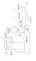
図6に従来の電池式電磁流量計の要部を示す(例えば、特許文献1,2参照)。同図において、1は測定管、2は測定管1内を流れる流体の流れ方向に対してその磁界の発生方向を垂直として配置された励磁コイル、3は励磁コイル2へ無励磁期間を挾んで正方向および負方向への励磁電流Iex(図7参照)を交互に供給し無励磁期間の前後に正励磁期間および負励磁期間を設ける励磁回路、4a,4bは測定管1内を流れる流体の流れ方向および励磁コイル2の発生磁界の方向と直交して測定管1内に対向して配置された一対の検出電極、5は接地電極、6は検出電極4a,4b間に得られる信号起電力を検出し、この検出される信号起電力に基づいて測定管1内を流れる流体の流量に応じて周波数が変わるデューティ比のパルス信号を流量測定信号として出力する流量測定回路、7は内蔵電池である。励磁回路3および流量測定回路6には内蔵電池7からの電源電圧VBが供給される。
FIG. 6 shows a main part of a conventional battery-type electromagnetic flow meter (see, for example,
この電池式電磁流量計において、励磁回路3は、励磁電流方向切替回路3−1や励磁電流値調整回路3−2などを備えている。励磁電流方向切替回路3−1は、流量測定回路6からの指示を受けて、励磁コイル2への励磁電流Iexの方向を無励磁期間を挟んで正方向および負方向へ交互に切り替える。励磁電流値調整回路3−2は、流量測定回路6からの指示を受けて、励磁コイル2への励磁電流Iexの値を調整する。流量測定回路6はCPU6−1を備えている。このCPU6−1から励磁電流方向切替回路3−1や励磁電流値調整回路3−2へ指示が出される。また、CPU6−1によって、検出電極4a,4b間に得られる信号起電力に基づく流量の算出が行われる。
In this battery type electromagnetic flow meter, the
この電池式電磁流量計では、動作電源を内蔵電池7に依存しており、内蔵電池7が消耗すれば新しい電池に交換しなければならない。このため、電池交換の周期を延ばすことが求められ、励磁コイル2への励磁電流Iexの供給に際して、正励磁期間と負励磁期間との間に無励磁期間を設けることによって、電力消費の削減を図っている。以下、この正励磁期間と負励磁期間との間に無励磁期間を設ける方式、すなわち無励磁期間の前後に正励磁期間および負励磁期間を設ける方式を3値励磁と呼ぶ。
In this battery type electromagnetic flow meter, the operating power source depends on the
特許文献3には、このような3値励磁の電磁流量計において、測定管の中が空になったり、電極に絶縁性の異物が付着した場合などに生じる異常を検知できるようにした電磁流量計が示されており、正励磁期間から無励磁期間への移行開始から所定期間が経過するまでの無励磁期間を第1の期間、負励磁期間から無励磁期間への移行開始から所定期間が経過するまでの無励磁期間を第2の期間とし、第1の期間における電極間の電圧差を求め、第2の期間における電極間の電圧差を求め、この第1の期間における電極間の電圧差と第2の期間における電極間の電圧差との差を演算し、この差が所定の基準値を超えたときに異常と判定するようにしている。
すなわち、特許文献3に示された電磁流量計では、励磁期間の切り替わり時に微分ノイズが発生し、測定管の中が空になったような場合、励磁コイルと電極との間に形成される浮遊容量により、その発生する微分ノイズが大きくなる。この微分ノイズを正励磁期間から無励磁期間への移行時の第1の期間における電極間の電圧差として検出し、また負励磁期間から無励磁期間への移行時の第2の期間における電極間の電圧差として検出し、この検出した電極間の電圧差に基づいて異常判定を行う。なお、第1の期間において電極間に発生する微分ノイズと第2の期間において電極間に発生する微分ノイズは極性が逆なので、第1の期間における電極間の電圧差と第2の期間における電極間の電圧差との差を求めることによって、電極間に発生する微分ノイズは2倍の大きさとして検出される。
That is, in the electromagnetic flow meter disclosed in
しかしながら、特許文献3に示された3値励磁の電磁流量計では、電極間の電圧差に基づいて異常を判定するようにしているので、すなわち図6に示した例で言えば、検出電極4aに生じる電圧と検出電極4bに生じる電圧との差に基づいて異常を判定するようにしているので、微分ノイズを小さな値としてしか検出することができず、異常判定の信頼性が低いという問題があった
However, in the ternary excitation electromagnetic flow meter disclosed in
本発明は、このような課題を解決するためになされたもので、その目的とするところは、微分ノイズを大きな値として検出し、異常判定の信頼性を高めることができる電磁流量計を提供することにある。 The present invention has been made to solve such problems, and an object of the present invention is to provide an electromagnetic flow meter that can detect differential noise as a large value and increase the reliability of abnormality determination. There is.
このような目的を達成するために本発明は、測定管内を流れる流体の流れ方向に対してその磁界の発生方向を垂直として配置された励磁コイルと、この励磁コイルへ無励磁期間を挟んで正方向および負方向への励磁電流を交互に供給し無励磁期間の前後に正励磁期間および負励磁期間を設ける励磁回路と、測定管内を流れる流体の流れ方向および励磁コイルの発生磁界の方向と直交して測定管内に対向して配置された第1および第2の電極と、この第1および第2の電極間に得られる信号起電力に基づいて測定管内を流れる流体の流量に応じた信号を流量測定信号として出力する流量測定回路とを備えた電磁流量計において、正励磁期間から無励磁期間への移行開始から所定期間が経過するまでの無励磁期間を第1の期間、負励磁期間から無励磁期間への移行開始から所定期間が経過するまでの無励磁期間を第2の期間とし、第1および第2の期間毎にその時の第1の電極に生じる電圧と第2の電極に生じる電圧との和を電極間の電圧和として求める電極間電圧和算出手段と、この電極間電圧和算出手段によって求められた第1および第2の期間毎の電極間の電圧和に基づいて電磁流量計の異常を判定する異常判定手段とを設けたものである。 In order to achieve such an object, the present invention provides an excitation coil arranged with the direction of generation of the magnetic field perpendicular to the flow direction of the fluid flowing in the measurement tube, and the excitation coil with a non-excitation period interposed therebetween. An excitation circuit that alternately supplies excitation current in the direction and negative direction and provides a positive excitation period and a negative excitation period before and after the non-excitation period, and is orthogonal to the flow direction of the fluid flowing in the measurement tube and the direction of the magnetic field generated by the excitation coil The first and second electrodes arranged opposite to each other in the measurement tube, and a signal corresponding to the flow rate of the fluid flowing in the measurement tube based on the signal electromotive force obtained between the first and second electrodes. In an electromagnetic flow meter including a flow measurement circuit that outputs a flow measurement signal, a non-excitation period from the start of transition from a positive excitation period to a non-excitation period until a predetermined period elapses from a first period and a negative excitation period. Nothing The non-excitation period from when the transition to the magnetic period starts until the predetermined period elapses is defined as the second period, and the voltage generated at the first electrode and the voltage generated at the second electrode at each of the first and second periods Between the electrodes, and an electromagnetic flow meter based on the voltage sum between the electrodes for each of the first and second periods obtained by the inter-electrode voltage sum calculation means And an abnormality determining means for determining the abnormality.
この発明によれば、第1および第2の期間毎にその時の第1の電極に生じる電圧と第2の電極に生じる電圧との和が電極間の電圧和として求められ、この求められた第1および第2の期間毎の電極間の電圧和に基づいて電磁流量計の異常が判定される。この場合、第1の電極に生じる電圧と第2の電極に生じる電圧との和をとることで、第1の電極に生じた微分ノイズと第2の電極に生じた微分ノイズとが加算され、微分ノイズが大きな値として検出されるものとなる。 According to the present invention, the sum of the voltage generated in the first electrode and the voltage generated in the second electrode at that time is obtained as the voltage sum between the electrodes for each of the first and second periods. Abnormality of the electromagnetic flow meter is determined based on the voltage sum between the electrodes for each of the first and second periods. In this case, the differential noise generated in the first electrode and the differential noise generated in the second electrode are added by taking the sum of the voltage generated in the first electrode and the voltage generated in the second electrode, The differential noise is detected as a large value.
なお、本発明において、第1の電極に生じる電圧と第2の電極に生じる電圧との和を電極間の電圧和として求めると、励磁コイルと電極との間に形成される浮遊容量により生じる微分ノイズ(以下、信号ノイズと呼ぶ)の成分だけではなく、商用ノイズや電極そのものに流れる1/fノイズなどによって生じるノイズ(以下、雑音ノイズと呼ぶ)の成分も大きな値となる。このような雑音ノイズが問題となる場合、電極間の電圧和から所定の周波数成分のみを抽出することによって、雑音ノイズとなる周波数成分を除去するようにしてもよい。 In the present invention, when the sum of the voltage generated at the first electrode and the voltage generated at the second electrode is obtained as the voltage sum between the electrodes, the differential generated by the stray capacitance formed between the exciting coil and the electrode. Not only the noise (hereinafter referred to as signal noise) component but also the noise (hereinafter referred to as noise noise) component caused by commercial noise or 1 / f noise flowing through the electrode itself has a large value. When such noise noise becomes a problem, the frequency component that becomes noise noise may be removed by extracting only a predetermined frequency component from the voltage sum between the electrodes.
本発明によれば、正励磁期間から無励磁期間への移行開始から所定期間が経過するまでの無励磁期間を第1の期間、負励磁期間から無励磁期間への移行開始から所定期間が経過するまでの無励磁期間を第2の期間とし、第1および第2の期間毎にその時の第1の電極に生じる電圧と第2の電極に生じる電圧との和を電極間の電圧和として求め、この求めた第1および第2の期間毎の電極間の電圧和に基づいて異常を判定するようにしたので、微分ノイズを大きな値として検出し、異常判定の信頼性を高めることができるようになる。 According to the present invention, the non-excitation period from the start of the transition from the positive excitation period to the non-excitation period is the first period, and the predetermined period has elapsed from the start of the transition from the negative excitation period to the non-excitation period. The non-excitation period until the second electrode is set as the second period, and the sum of the voltage generated at the first electrode and the voltage generated at the second electrode at that time is obtained as the voltage sum between the electrodes for each of the first and second periods. Since the abnormality is determined based on the obtained voltage sum between the electrodes for each of the first and second periods, the differential noise is detected as a large value so that the reliability of the abnormality determination can be improved. become.
以下、本発明を実施の形態に基づき詳細に説明する。
図1はこの発明に係る電磁流量計の一実施の形態の要部を示す図である。同図において、図6と同一符号は図6を参照して説明した構成要素と同一或いは同等構成要素を示し、その説明は省略する。
Hereinafter, the present invention will be described in detail based on embodiments.
FIG. 1 is a diagram showing a main part of an embodiment of an electromagnetic flow meter according to the present invention. In FIG. 6, the same reference numerals as those in FIG. 6 denote the same or equivalent components as those described with reference to FIG.
この実施の形態では、電磁流量計内に異常検出回路8を設け、検出電極4aに生じる電圧Vaおよび検出電極4bに生じる電圧Vbを異常検出回路8へ与えるようにしている。
In this embodiment, the
図2に異常検出回路8のブロック図を示す。異常検出回路8は、バンドパスフィルタ8−1,8−2、加算回路8−3、増幅回路8−4、周波数成分抽出フィルタ8−5、直流信号変換回路8−6、ローパスフィルタ8−7、増幅回路8−8および異常判定回路8−9を備えている。
FIG. 2 shows a block diagram of the
図3にこの電磁流量計における微分ノイズの発生状況を例示する。図3(a)は励磁電流Iexである。励磁電流Iexは、無励磁期間を挟んで正方向および負方向へ交互に切り替えて、励磁コイル2に供給される。これにより、無励磁期間の前後に正励磁期間および負励磁期間が設けられる。図3(b)は検出電極4aに生じる微分ノイズであり、図3(c)は検出電極4bに生じる微分ノイズであり、励磁期間の切り替わり時に発生する。
FIG. 3 shows an example of the occurrence of differential noise in this electromagnetic flow meter. FIG. 3A shows the excitation current Iex. The exciting current Iex is supplied to the
以下、異常検出回路8内の各回路の機能を交えながら、その動作について説明する。
異常検出回路8において、バンドパスフィルタ8−1は、検出電極4aに生じる電圧Vaを入力とし、正励磁期間から無励磁期間への移行開始から所定期間が経過するまでの無励磁期間を第1の期間T1、負励磁期間から無励磁期間への移行開始から所定期間が経過するまでの無励磁期間を第2の期間T2とし、この第1の期間T1および第2の期間T2における入力電圧Vaを通過させ、後段の加算回路8−3へ送る。
Hereinafter, the operation of each circuit in the
In the
バンドパスフィルタ8−2は、検出電極4bに生じる電圧Vbを入力とし、正励磁期間から無励磁期間への移行開始から所定期間が経過するまでの無励磁期間を第1の期間T1、負励磁期間から無励磁期間への移行開始から所定期間が経過するまでの無励磁期間を第2の期間T2とし、この第1の期間T1および第2の期間T2における入力電圧Vbを通過させ、後段の加算回路8−3へ送る。
The band pass filter 8-2 receives the voltage Vb generated at the
加算回路8−3は、バンドパスフィルタ8−1からの入力電圧Vaとバンドパスフィルタ8−2からの入力電圧Vbとを加算し(Va+Vb)、その絶対値(|Va+Vb|)を検出電極4a,4b間の電圧和(電極間電圧和)Vabとして増幅回路8−4へ送る。増幅回路8−4は、加算回路8−3からの電極間電圧和Vabを増幅し、周波数成分抽出フィルタ8−5へ送る。
The adder circuit 8-3 adds the input voltage Va from the bandpass filter 8-1 and the input voltage Vb from the bandpass filter 8-2 (Va + Vb), and uses the absolute value (| Va + Vb |) as the
周波数成分抽出フィルタ8−5は、増幅回路8−4によって増幅された加算回路8−3からの電極間電圧和Vabを入力とし、この電極間電圧和Vabから所定の周波数成分のみを抽出し、直流信号変換回路8−6へ送る。 The frequency component extraction filter 8-5 receives the inter-electrode voltage sum Vab from the adder circuit 8-3 amplified by the amplifier circuit 8-4, and extracts only a predetermined frequency component from the inter-electrode voltage sum Vab. Send to DC signal conversion circuit 8-6.
〔周波数成分抽出フィルタでの所定の周波数成分の抽出〕
例えば、測定管1の中が空になった場合、励磁コイル2と検出電極4aおよび4bとの間に形成される浮遊容量により、検出電極4aおよび4bに生じる微分ノイズが大きくなる。これにより、第1の期間T1においては、バンドパスフィルタ8−1からの入力電圧Vaおよびバンドパスフィルタ8−2からの入力電圧Vbが共に負方向へ大きくなり、この入力電圧VaとVbとを加算して得られる電極間電圧和Vabも大きくなる。また、第2の期間T2においては、バンドパスフィルタ8−1からの入力電圧Vaおよびバンドパスフィルタ8−2からの入力電圧Vbが共に正方向へ大きくなり、この入力電圧VaとVbとを加算して得られる電極間電圧和Vabも大きくなる。
[Extraction of predetermined frequency component by frequency component extraction filter]
For example, when the inside of the measuring
この場合、電極間電圧和Vabは、励磁コイル2と検出電極4aおよび4bとの間に形成される浮遊容量により生じる微分ノイズ(信号ノイズ)の成分だけではなく、商用ノイズや電極そのものに流れる1/fノイズなどによって生じるノイズ(雑音ノイズ)の成分も大きな値となる。
In this case, the interelectrode voltage sum Vab is not only a component of differential noise (signal noise) generated by the stray capacitance formed between the
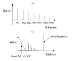
本実施の形態では、このような雑音ノイズとなる周波数成分を除去するために、周波数成分抽出フィルタ8−5において、電極間電圧和Vabから所定の周波数成分のみを抽出するようにしている。具体的には、5Hz超〜50Hz未満の周波数成分のみを抽出する。 In the present embodiment, in order to remove such a frequency component that causes noise, the frequency component extraction filter 8-5 extracts only a predetermined frequency component from the interelectrode voltage sum Vab. Specifically, only the frequency component exceeding 5 Hz to less than 50 Hz is extracted.
図4に電極間電圧和Vabの周波数スペクトラムの解析結果を示す。図4(a)において、fexは励磁周波数であり、電極間電圧和Vabはfex、3fex、5fex、7fex、9fex、10fex、11fexの信号ノイズを含む。但し、検出電極4a,4bには、満水時または空時に、図4(b)に示すような周波数成分(5Hz以下の1/fノイズ、50Hzまたは60Hzのノイズ)を持つ雑音ノイズが重畳してくる。そこで、周波数成分抽出フィルタ8−5において、5Hz超〜50Hz未満の周波数成分のみを抽出することにより、雑音ノイズとなる周波数成分を除去する。
FIG. 4 shows the analysis result of the frequency spectrum of the interelectrode voltage sum Vab. In FIG. 4A, fex is an excitation frequency, and the inter-electrode voltage sum Vab includes signal noise of fex, 3fex, 5fex, 7fex, 9fex, 10fex, and 11fex. However, noise noise having a frequency component (1 / f noise of 5 Hz or less, 50 Hz or 60 Hz noise) as shown in FIG. 4B is superimposed on the
直流信号変換回路8−6は、周波数成分抽出フィルタ8−5によって抽出された第1の期間T1および第2の期間T2毎の所定の周波数成分の電圧和について、その期間中の電圧和が所定値よりも高い部分のみをサンプリングし、このサンプリングした電圧和の積算値に応じた値の直流信号に変換する。この場合、直流信号変換回路8−6は、サンプルホールド回路として構成される。 The DC signal conversion circuit 8-6 has a predetermined voltage sum of a predetermined frequency component for each of the first period T1 and the second period T2 extracted by the frequency component extraction filter 8-5. Only a portion higher than the value is sampled and converted to a DC signal having a value corresponding to the integrated value of the sampled voltage sum. In this case, the DC signal conversion circuit 8-6 is configured as a sample hold circuit.
なお、直流信号変換回路8−6として、周波数成分抽出フィルタ8−5によって抽出された第1の期間T1および第2の期間T2毎の所定の周波数成分の電圧和について、その期間中の電圧和の最大値をピーク値として保持し、この保持した電圧和のピーク値に応じた値の直流信号に変換するピークホールド回路を用いるようにしてもよい。 As the DC signal conversion circuit 8-6, the voltage sum of the predetermined frequency components for each of the first period T1 and the second period T2 extracted by the frequency component extraction filter 8-5 is used. May be used as a peak value, and a peak hold circuit for converting to a DC signal having a value corresponding to the peak value of the held voltage sum may be used.
直流信号変換回路8−6によって変換された直流信号は、ローパスフィルタ8−7を介し、増幅回路8−8で増幅されて、異常判定回路8−9へ与えられる。ローパスフィルタ8−7は、所定の周波数以下の信号のみを通過させることにより、直流信号変換回路8−6からの直流信号に含まれるノイズ成分を取り除く。 The DC signal converted by the DC signal conversion circuit 8-6 is amplified by the amplifier circuit 8-8 via the low-pass filter 8-7, and is given to the abnormality determination circuit 8-9. The low-pass filter 8-7 removes a noise component included in the DC signal from the DC signal conversion circuit 8-6 by allowing only a signal having a predetermined frequency or less to pass therethrough.
異常判定回路8−9は、送られてくる直流信号の値と所定の基準値とを比較し、直流信号の値が基準値を超えた場合に異常検知信号を出力する。 The abnormality determination circuit 8-9 compares the value of the DC signal that is sent with a predetermined reference value, and outputs an abnormality detection signal when the value of the DC signal exceeds the reference value.
このようにして、本実施の形態では、検出電極4aに生じる電圧Vaと検出電極4bに生じる電圧との和を電極間電圧和Vabとして求め、この電極間電圧和Vabに基づいて異常を判定するようにしているので、微分ノイズを大きな値として検出し、異常判定の信頼性を高めることができるようになる。
Thus, in the present embodiment, the sum of the voltage Va generated at the
図5に測定管1内の流体を排水→空にしたときの異常判定回路8−9に与えられる直流信号(サンプルホールド信号)と異常判定回路8−9からの異常検知信号(コンパレータ出力)の関係を例示する。この例では、排水完了後10秒程度で、測定管1内が空になったことを検知することができている。
FIG. 5 shows a DC signal (sample hold signal) given to the abnormality determination circuit 8-9 when the fluid in the measuring
なお、上述した実施の形態では、異常検出回路8の構成要素として周波数成分抽出フィルタ8−5を設けるようにしたが、必ずしも周波数成分抽出フィルタ8−5を設けなくてもよく、ローパスフィルタ8−7や増幅回路8−4,8−8を省略した構成としたりしてもよい。
In the above-described embodiment, the frequency component extraction filter 8-5 is provided as a component of the
また、上述した実施の形態では、バンドパスフィルタ8−1と8−2を加算回路8−3の前段に入れていたが、代わりに加算回路8−3の後段に1つのバンドパスフィルタを入れてもよい。 In the above-described embodiment, the bandpass filters 8-1 and 8-2 are placed before the adder circuit 8-3. Instead, one bandpass filter is placed after the adder circuit 8-3. May be.
また、上述した実施の形態において、第1の期間T1および第2の期間T2は、信号ノイズの発生が予想される期間よりも長ければよく、無励磁期間が終了するまでの全期間としてもよい。 In the above-described embodiment, the first period T1 and the second period T2 may be longer than the period during which signal noise is expected to occur, and may be the entire period until the non-excitation period ends. .
また、上述した実施の形態では、第1の期間T1および第2の期間T2毎に電極間電圧和Vabを求め、この求めた第1の期間T1および第2の期間T2毎の電極間電圧和Vabより得られる直流信号の値と基準値とを比較して異常判定を行うようにしたが、第1の期間T1で求められた電極間電圧和Vabと第2の期間T2で求められた電極間電圧和Vabとを加算し、この電極間電圧和の加算値より得られる直流信号の値と基準値とを比較して異常判定を行うようにしてもよい。 In the above-described embodiment, the interelectrode voltage sum Vab is obtained for each of the first period T1 and the second period T2, and the obtained interelectrode voltage sum for each of the first period T1 and the second period T2 is obtained. The abnormality is determined by comparing the value of the DC signal obtained from Vab with the reference value, but the interelectrode voltage sum Vab obtained in the first period T1 and the electrode obtained in the second period T2. The abnormality sum may be determined by adding the inter-voltage sum Vab and comparing the value of the DC signal obtained from the sum of the inter-electrode voltage sums with a reference value.
また、上述した実施の形態では、流量測定回路6とは別個に設けた異常検出回路8で測定管1の中が空になったり、検出電極4a,4bに絶縁性の異物が付着した場合などに生じる異常を検知するものとしたが、流量測定回路6内のCPU6−1のプログラムに従う処理動作として、同様の機能を得るようにしてもよい。
In the above-described embodiment, the
本発明の電磁流量計は、導電性を有する流体の流量を測定する電磁流量計として、各種プロセス系において利用することが可能である。 The electromagnetic flow meter of the present invention can be used in various process systems as an electromagnetic flow meter for measuring the flow rate of a fluid having conductivity.
1…測定管、2…励磁コイル、3…励磁回路、3−1…励磁電流方向切替回路、3−2…励磁電流値調整回路、4a,4b…検出電極、5…接地電極、6…流量測定回路、6−1…CPU、7…内蔵電池、8…異常検出回路、8−1,8−2…バンドパスフィルタ、8−3…加算回路、8−4…増幅回路、8−5…周波数成分抽出フィルタ、8−6…直流信号変換回路、8−7…ローパスフィルタ、8−8…増幅回路、8−9…異常判定回路。
DESCRIPTION OF
Claims (5)
前記正励磁期間から前記無励磁期間への移行開始から所定期間が経過するまでの無励磁期間を第1の期間、前記負励磁期間から前記無励磁期間への移行開始から所定期間が経過するまでの無励磁期間を第2の期間とし、前記第1および第2の期間毎にその時の前記第1の電極に生じる電圧と前記第2の電極に生じる電圧との和を電極間の電圧和として求める電極間電圧和算出手段と、
この電極間電圧和算出手段によって求められた前記第1および第2の期間毎の前記電極間の電圧和に基づいて前記電磁流量計の異常を判定する異常判定手段と
を備えることを特徴とする電磁流量計。 An excitation coil arranged with the direction of magnetic field generation perpendicular to the flow direction of the fluid flowing in the measurement tube, and excitation currents in the positive and negative directions are alternately supplied to this excitation coil with no excitation period. An excitation circuit that provides a positive excitation period and a negative excitation period before and after the non-excitation period, and an opposed arrangement in the measurement pipe orthogonal to the flow direction of the fluid flowing in the measurement pipe and the direction of the magnetic field generated by the excitation coil The first and second electrodes, and the flow rate measurement that outputs a signal corresponding to the flow rate of the fluid flowing through the measurement tube as a flow rate measurement signal based on the signal electromotive force obtained between the first and second electrodes. In an electromagnetic flow meter with a circuit,
The non-excitation period from the start of transition from the positive excitation period to the non-excitation period until the predetermined period elapses is the first period, and from the start of transition from the negative excitation period to the non-excitation period until the predetermined period elapses The non-excitation period is the second period, and the sum of the voltage generated at the first electrode and the voltage generated at the second electrode at each time of the first and second periods is defined as the voltage sum between the electrodes. The inter-electrode voltage sum calculation means to be obtained;
An abnormality determining means for determining an abnormality of the electromagnetic flow meter based on the voltage sum between the electrodes for each of the first and second periods obtained by the inter-electrode voltage sum calculating means. Electromagnetic flow meter.
前記電極間電圧和算出手段によって求められた前記第1および第2の期間毎の前記電極間の電圧和から所定の周波数成分のみを抽出する周波数成分抽出手段を備え、
前記異常判定手段は、
前記周波数成分抽出手段によって抽出された前記第1および第2の期間毎の前記電極間の所定の周波数成分の電圧和に基づいて前記電磁流量計の異常を判定する
ことを特徴とする電磁流量計。 The electromagnetic flow meter according to claim 1,
Frequency component extraction means for extracting only a predetermined frequency component from the voltage sum between the electrodes for each of the first and second periods determined by the interelectrode voltage sum calculation means;
The abnormality determining means includes
An abnormality of the electromagnetic flow meter is determined based on a voltage sum of a predetermined frequency component between the electrodes for each of the first and second periods extracted by the frequency component extraction means. .
前記周波数成分抽出手段によって抽出された前記第1および第2の期間毎の前記電極間の所定の周波数成分の電圧和について、その期間中の電圧和が所定値よりも高い部分のみをサンプリングし、このサンプリングした電圧和の積算値に応じた値の直流信号に変換する直流信号変換手段を備え、
前記異常判定手段は、
前記直流信号変換手段によって変換された直流信号の値と所定の基準値とを比較し、直流信号の値が基準値を超えた場合に異常信号を出力する
ことを特徴とする電磁流量計。 The electromagnetic flow meter according to claim 2,
For the voltage sum of the predetermined frequency component between the electrodes for each of the first and second periods extracted by the frequency component extracting means, only a portion where the voltage sum during that period is higher than a predetermined value is sampled. DC signal conversion means for converting into a DC signal of a value corresponding to the integrated value of the sampled voltage sum,
The abnormality determining means includes
An electromagnetic flowmeter characterized by comparing the value of the DC signal converted by the DC signal converting means with a predetermined reference value and outputting an abnormal signal when the value of the DC signal exceeds the reference value.
前記周波数成分抽出手段によって抽出された前記第1および第2の期間毎の前記電極間の所定の周波数成分の電圧和について、その期間中の電圧和の最大値をピーク値として保持し、この保持した電圧和のピーク値に応じた値の直流信号に変換する直流信号変換手段を備え、
前記異常判定手段は、
前記直流信号変換手段によって変換された直流信号の値と所定の基準値とを比較し、直流信号の値が基準値を超えた場合に異常信号を出力する
ことを特徴とする電磁流量計。 The electromagnetic flow meter according to claim 2,
For the voltage sum of the predetermined frequency component between the electrodes for each of the first and second periods extracted by the frequency component extracting means, the maximum value of the voltage sum during that period is held as a peak value, and this holding DC signal conversion means for converting into a DC signal of a value according to the peak value of the voltage sum,
The abnormality determining means includes
An electromagnetic flowmeter characterized by comparing the value of the DC signal converted by the DC signal converting means with a predetermined reference value and outputting an abnormal signal when the value of the DC signal exceeds the reference value.
前記直流信号変換手段と前記異常判定回路との間に所定の周波数以下の信号を通過させるローパスフィルタが設けられている
ことを特徴とする電磁流量計。 In the electromagnetic flowmeter according to claim 3 or 4,
A low-pass filter that allows a signal having a predetermined frequency or less to pass is provided between the DC signal conversion means and the abnormality determination circuit.
Priority Applications (4)
| Application Number | Priority Date | Filing Date | Title |
|---|---|---|---|
| JP2010079353A JP5444086B2 (en) | 2010-03-30 | 2010-03-30 | Electromagnetic flow meter |
| US13/071,815 US8739636B2 (en) | 2010-03-30 | 2011-03-25 | Electromagnetic flow meter having a circuit that provides positive and negative magnetic excitation electric currents to a magnetic excitation coil |
| EP11160117A EP2372317A1 (en) | 2010-03-30 | 2011-03-29 | Electromagnetic flow meter |
| CN201110090018.1A CN102243087B (en) | 2010-03-30 | 2011-03-30 | Electromagnetic flow meter |
Applications Claiming Priority (1)
| Application Number | Priority Date | Filing Date | Title |
|---|---|---|---|
| JP2010079353A JP5444086B2 (en) | 2010-03-30 | 2010-03-30 | Electromagnetic flow meter |
Publications (3)
| Publication Number | Publication Date |
|---|---|
| JP2011209231A JP2011209231A (en) | 2011-10-20 |
| JP2011209231A5 JP2011209231A5 (en) | 2014-01-16 |
| JP5444086B2 true JP5444086B2 (en) | 2014-03-19 |
Family
ID=44280697
Family Applications (1)
| Application Number | Title | Priority Date | Filing Date |
|---|---|---|---|
| JP2010079353A Active JP5444086B2 (en) | 2010-03-30 | 2010-03-30 | Electromagnetic flow meter |
Country Status (4)
| Country | Link |
|---|---|
| US (1) | US8739636B2 (en) |
| EP (1) | EP2372317A1 (en) |
| JP (1) | JP5444086B2 (en) |
| CN (1) | CN102243087B (en) |
Cited By (2)
| Publication number | Priority date | Publication date | Assignee | Title |
|---|---|---|---|---|
| JP2014181918A (en) * | 2013-03-18 | 2014-09-29 | Azbil Corp | Signal amplifier circuit for electromagnetic flow meter |
| US10697812B2 (en) | 2017-09-14 | 2020-06-30 | Azbil Corporation | Error detection circuit and error detection method of electromagnetic flow meter and electromagnetic flow meter |
Families Citing this family (16)
| Publication number | Priority date | Publication date | Assignee | Title |
|---|---|---|---|---|
| JP5973775B2 (en) | 2012-04-27 | 2016-08-23 | 株式会社東芝 | Electromagnetic flow meter, self-diagnosis method of its excitation circuit |
| JP5574191B2 (en) * | 2012-06-26 | 2014-08-20 | 横河電機株式会社 | Electromagnetic flowmeter operation verification system |
| JP5973897B2 (en) * | 2012-12-04 | 2016-08-23 | アズビル株式会社 | Electromagnetic flow meter |
| JP5939472B2 (en) * | 2014-02-25 | 2016-06-22 | 横河電機株式会社 | Electromagnetic flow meter, erroneous wiring detection device, and erroneous wiring detection method |
| JP6183309B2 (en) * | 2014-07-11 | 2017-08-23 | 横河電機株式会社 | Flow meter and insulation deterioration diagnosis system |
| US9658089B2 (en) * | 2014-10-01 | 2017-05-23 | Finetek Co., Ltd. | Electromagnetic flowmeter with voltage-amplitude conductivity-sensing function for a liquid in a tube |
| JP6229852B2 (en) * | 2015-03-05 | 2017-11-15 | 横河電機株式会社 | Electromagnetic flow meter |
| EP3064905B1 (en) | 2015-03-05 | 2019-07-31 | Yokogawa Electric Corporation | Electromagnetic flowmeter |
| JP6217687B2 (en) * | 2015-04-24 | 2017-10-25 | 横河電機株式会社 | Field equipment |
| GB2542433A (en) | 2015-09-21 | 2017-03-22 | Abb Ltd | Method and apparatus for interference reduction |
| JP6485407B2 (en) * | 2016-06-01 | 2019-03-20 | 横河電機株式会社 | Electromagnetic flow meter and incorrect wiring detection method |
| DE102016211577A1 (en) | 2016-06-28 | 2017-12-28 | Siemens Aktiengesellschaft | Magnetic-inductive flowmeter |
| JP6458784B2 (en) * | 2016-08-03 | 2019-01-30 | 横河電機株式会社 | Drive circuit and electromagnetic flow meter |
| DE102016124976A1 (en) | 2016-12-20 | 2018-06-21 | Endress+Hauser Flowtec Ag | Method for operating a magnetic-inductive flowmeter and such a flowmeter |
| US11131571B2 (en) * | 2019-07-22 | 2021-09-28 | Georg Fischer Signett LLC | Magnetic flowmeter assembly with glitch removing capability |
| DE102021208598A1 (en) * | 2021-08-06 | 2023-02-09 | Siemens Aktiengesellschaft | Noisy flow measurement method, electromagnetic flowmeter and computer program product |
Family Cites Families (12)
| Publication number | Priority date | Publication date | Assignee | Title |
|---|---|---|---|---|
| JPH0360027U (en) * | 1989-10-17 | 1991-06-13 | ||
| JP2707762B2 (en) * | 1989-10-31 | 1998-02-04 | 横河電機株式会社 | Electromagnetic flow meter |
| JPH06174513A (en) * | 1992-12-09 | 1994-06-24 | Fuji Electric Co Ltd | Emptiness detection circuit of electromagnetic flowmeter |
| US5426984A (en) | 1993-09-02 | 1995-06-27 | Rosemount Inc. | Magnetic flowmeter with empty pipe detector |
| JP3018311B2 (en) | 1995-02-03 | 2000-03-13 | 株式会社山武 | Electromagnetic flow meter |
| JP3161307B2 (en) * | 1995-11-02 | 2001-04-25 | 横河電機株式会社 | Electromagnetic flow meter |
| JPH09129848A (en) | 1995-11-06 | 1997-05-16 | Mitsubishi Electric Corp | Manufacture of semiconductor device having capacitor |
| US6611775B1 (en) | 1998-12-10 | 2003-08-26 | Rosemount Inc. | Electrode leakage diagnostics in a magnetic flow meter |
| JP4300562B2 (en) * | 2000-03-30 | 2009-07-22 | 横河電機株式会社 | Electromagnetic flow meter |
| DE10118003A1 (en) * | 2001-04-10 | 2002-10-24 | Krohne Messtechnik Kg | Magnetic-inductive flowmeter and magnetic-inductive flowmeter |
| JP2003028684A (en) | 2001-07-17 | 2003-01-29 | Yokogawa Electric Corp | Electromagnetic flowmeter |
| JP2010079353A (en) | 2008-09-24 | 2010-04-08 | Koyo Electronics Ind Co Ltd | Programmable controller and control system |
-
2010
- 2010-03-30 JP JP2010079353A patent/JP5444086B2/en active Active
-
2011
- 2011-03-25 US US13/071,815 patent/US8739636B2/en active Active
- 2011-03-29 EP EP11160117A patent/EP2372317A1/en not_active Withdrawn
- 2011-03-30 CN CN201110090018.1A patent/CN102243087B/en not_active Expired - Fee Related
Cited By (2)
| Publication number | Priority date | Publication date | Assignee | Title |
|---|---|---|---|---|
| JP2014181918A (en) * | 2013-03-18 | 2014-09-29 | Azbil Corp | Signal amplifier circuit for electromagnetic flow meter |
| US10697812B2 (en) | 2017-09-14 | 2020-06-30 | Azbil Corporation | Error detection circuit and error detection method of electromagnetic flow meter and electromagnetic flow meter |
Also Published As
| Publication number | Publication date |
|---|---|
| US8739636B2 (en) | 2014-06-03 |
| US20110239778A1 (en) | 2011-10-06 |
| JP2011209231A (en) | 2011-10-20 |
| CN102243087B (en) | 2013-01-16 |
| EP2372317A1 (en) | 2011-10-05 |
| CN102243087A (en) | 2011-11-16 |
Similar Documents
| Publication | Publication Date | Title |
|---|---|---|
| JP5444086B2 (en) | Electromagnetic flow meter | |
| JP2568620B2 (en) | Electromagnetic flow meter | |
| JP2011232136A (en) | Electromagnetic flowmeter | |
| JP5458221B2 (en) | Electromagnetic flow meter | |
| EP3040728B1 (en) | Stacked battery impedance measurement device and measurement method | |
| JP5843670B2 (en) | Excitation circuit of electromagnetic flow meter | |
| EP2259028B1 (en) | Electromagnetic flow meter | |
| JP4424511B2 (en) | Electromagnetic flow meter and electromagnetic flow meter system | |
| JP6240059B2 (en) | Apparatus and method for estimating deterioration state of primary smoothing capacitor in power supply device | |
| JP2009195093A (en) | Dc current component detecting method, dc current component detecting device, and system interconnecting generator | |
| JP2001050784A (en) | Magnetic induction type flow measuring method | |
| JP4532359B2 (en) | DC component detection circuit | |
| JP5997633B2 (en) | Electromagnetic flow meter | |
| JP4851149B2 (en) | Electromagnetic flow meter | |
| JP6077843B2 (en) | Electromagnetic flow meter | |
| JP2012013578A (en) | Infrared detector | |
| JP2010178422A (en) | Ground fault detection device for vehicle | |
| JP5382048B2 (en) | Differential signal failure detection apparatus and differential signal failure detection method | |
| JP6458375B2 (en) | Impedance measuring device | |
| US20220368212A1 (en) | Systems and methods for current sensing and control for multiphase power converters | |
| JP5530331B2 (en) | Electromagnetic flow meter | |
| JP2005207984A (en) | Electromagnetic flowmeter | |
| JP5522474B2 (en) | Electromagnetic flow meter | |
| JPH10221134A (en) | Electromagnetic flowmeter | |
| JP5977702B2 (en) | Excitation circuit of electromagnetic flow meter |
Legal Events
| Date | Code | Title | Description |
|---|---|---|---|
| A621 | Written request for application examination |
Free format text: JAPANESE INTERMEDIATE CODE: A621 Effective date: 20130124 |
|
| A977 | Report on retrieval |
Free format text: JAPANESE INTERMEDIATE CODE: A971007 Effective date: 20131025 |
|
| A521 | Request for written amendment filed |
Free format text: JAPANESE INTERMEDIATE CODE: A523 Effective date: 20131121 |
|
| TRDD | Decision of grant or rejection written | ||
| A01 | Written decision to grant a patent or to grant a registration (utility model) |
Free format text: JAPANESE INTERMEDIATE CODE: A01 Effective date: 20131217 |
|
| A61 | First payment of annual fees (during grant procedure) |
Free format text: JAPANESE INTERMEDIATE CODE: A61 Effective date: 20131220 |
|
| R150 | Certificate of patent or registration of utility model |
Ref document number: 5444086 Country of ref document: JP Free format text: JAPANESE INTERMEDIATE CODE: R150 Free format text: JAPANESE INTERMEDIATE CODE: R150 |