JP5443085B2 - Document presentation device - Google Patents
Document presentation device Download PDFInfo
- Publication number
- JP5443085B2 JP5443085B2 JP2009174855A JP2009174855A JP5443085B2 JP 5443085 B2 JP5443085 B2 JP 5443085B2 JP 2009174855 A JP2009174855 A JP 2009174855A JP 2009174855 A JP2009174855 A JP 2009174855A JP 5443085 B2 JP5443085 B2 JP 5443085B2
- Authority
- JP
- Japan
- Prior art keywords
- mask
- mark
- image
- original image
- composite
- Prior art date
- Legal status (The legal status is an assumption and is not a legal conclusion. Google has not performed a legal analysis and makes no representation as to the accuracy of the status listed.)
- Active
Links
- 239000002131 composite material Substances 0.000 claims description 69
- 239000000463 material Substances 0.000 claims description 54
- 238000001514 detection method Methods 0.000 claims description 27
- 238000000034 method Methods 0.000 claims description 21
- 230000008569 process Effects 0.000 claims description 13
- 238000004519 manufacturing process Methods 0.000 claims 2
- 238000012545 processing Methods 0.000 description 23
- 238000012986 modification Methods 0.000 description 9
- 238000010586 diagram Methods 0.000 description 7
- 239000004973 liquid crystal related substance Substances 0.000 description 7
- 230000000873 masking effect Effects 0.000 description 7
- 230000004048 modification Effects 0.000 description 7
- 230000006870 function Effects 0.000 description 6
- 239000000203 mixture Substances 0.000 description 4
- 238000006243 chemical reaction Methods 0.000 description 3
- 238000003384 imaging method Methods 0.000 description 3
- 230000003287 optical effect Effects 0.000 description 3
- 238000004590 computer program Methods 0.000 description 2
- 238000013461 design Methods 0.000 description 2
- PXFBZOLANLWPMH-UHFFFAOYSA-N 16-Epiaffinine Natural products C1C(C2=CC=CC=C2N2)=C2C(=O)CC2C(=CC)CN(C)C1C2CO PXFBZOLANLWPMH-UHFFFAOYSA-N 0.000 description 1
- 230000008901 benefit Effects 0.000 description 1
- 230000015572 biosynthetic process Effects 0.000 description 1
- 238000012217 deletion Methods 0.000 description 1
- 230000037430 deletion Effects 0.000 description 1
- 238000003786 synthesis reaction Methods 0.000 description 1
- 230000002194 synthesizing effect Effects 0.000 description 1
- 230000009466 transformation Effects 0.000 description 1
Images


Classifications
-
- H—ELECTRICITY
- H04—ELECTRIC COMMUNICATION TECHNIQUE
- H04N—PICTORIAL COMMUNICATION, e.g. TELEVISION
- H04N1/00—Scanning, transmission or reproduction of documents or the like, e.g. facsimile transmission; Details thereof
- H04N1/387—Composing, repositioning or otherwise geometrically modifying originals
- H04N1/3872—Repositioning or masking
- H04N1/3873—Repositioning or masking defined only by a limited number of coordinate points or parameters, e.g. corners, centre; for trimming
-
- H—ELECTRICITY
- H04—ELECTRIC COMMUNICATION TECHNIQUE
- H04N—PICTORIAL COMMUNICATION, e.g. TELEVISION
- H04N1/00—Scanning, transmission or reproduction of documents or the like, e.g. facsimile transmission; Details thereof
- H04N1/387—Composing, repositioning or otherwise geometrically modifying originals
- H04N1/3872—Repositioning or masking
-
- H—ELECTRICITY
- H04—ELECTRIC COMMUNICATION TECHNIQUE
- H04N—PICTORIAL COMMUNICATION, e.g. TELEVISION
- H04N1/00—Scanning, transmission or reproduction of documents or the like, e.g. facsimile transmission; Details thereof
- H04N1/46—Colour picture communication systems
- H04N1/56—Processing of colour picture signals
- H04N1/60—Colour correction or control
- H04N1/62—Retouching, i.e. modification of isolated colours only or in isolated picture areas only
- H04N1/626—Detection of non-electronic marks, e.g. fluorescent markers
-
- H—ELECTRICITY
- H04—ELECTRIC COMMUNICATION TECHNIQUE
- H04N—PICTORIAL COMMUNICATION, e.g. TELEVISION
- H04N23/00—Cameras or camera modules comprising electronic image sensors; Control thereof
-
- H—ELECTRICITY
- H04—ELECTRIC COMMUNICATION TECHNIQUE
- H04N—PICTORIAL COMMUNICATION, e.g. TELEVISION
- H04N5/00—Details of television systems
- H04N5/222—Studio circuitry; Studio devices; Studio equipment
- H04N5/262—Studio circuits, e.g. for mixing, switching-over, change of character of image, other special effects ; Cameras specially adapted for the electronic generation of special effects
- H04N5/2628—Alteration of picture size, shape, position or orientation, e.g. zooming, rotation, rolling, perspective, translation
Description
本発明は、資料を撮影して画像を生成し、この画像を外部の表示装置に表示する資料提示装置に関するものである。 The present invention relates to a material presentation device that captures a material to generate an image and displays the image on an external display device.
例えば、特許文献1〜3に記載されたような資料提示装置において、従来、撮影した画像の一部をマスクする機能を備えるものがある。このような機能を用いれば、例えば、学校等の授業において、答案用紙の正答部分を隠して生徒に視聴させることなどが可能になる。 For example, some document presentation apparatuses such as those described in Patent Documents 1 to 3 have a function of masking part of a captured image. If such a function is used, for example, in a class at school or the like, it is possible to hide the correct answer part of the answer sheet so that the student can watch it.
しかし従来は、マスク機能を利用する度に、リモコンや本体の操作部によってマスクする領域を指定する必要があり、その操作が煩わしかった。また、指定されたマスク領域は、表示画面上において固定されているため、撮影する資料が動いてしまうと、意図しない部分がマスクされたり露出してしまう場合があった。 However, conventionally, every time the mask function is used, it is necessary to designate an area to be masked by the remote controller or the operation unit of the main body, which is troublesome. In addition, since the designated mask area is fixed on the display screen, an unintended portion may be masked or exposed when a material to be photographed moves.
これらの問題を踏まえ、本発明が解決しようとする課題は、より利便性の高いマスク処理が可能な資料提示装置を提供することにある。 In view of these problems, the problem to be solved by the present invention is to provide a material presentation device capable of more convenient mask processing.
本発明は、上述の課題の少なくとも一部を解決するためになされたものであり、以下の形態又は適用例として実現することが可能である。
本発明の第1の形態は、資料提示装置であって、
被写体を撮影して原画像を生成する撮影部と、
所定の第1のマークが前記原画像内に含まれているか否かを解析し、前記第1のマークが前記原画像内に含まれている場合に、前記原画像内の前記第1のマークの存在位置を検出する検出部と、
前記原画像の少なくとも一部をマスクするマスク画像を前記原画像に合成するための合成位置と、前記第1のマークの存在位置との相対的な位置関係を記憶する記憶部と、
前記検出された存在位置と前記相対的な位置関係とに応じて前記合成位置を決定し、前記原画像内の前記決定された合成位置に前記マスク画像を合成して合成画像を生成する合成画像生成部と、
前記合成画像を出力する出力部と
を備え、
前記検出部は、前記第1のマークが前記原画像内に含まれている場合に、更に、前記第1のマークの傾きを検出し、
前記合成画像生成部は、前記検出された傾きに応じて、前記合成位置と前記マスク画像の傾きとを調整する
資料提示装置である。
このような形態では、原画像内に第1のマークが含まれる場合には、その第1のマークの存在位置と、予め定められた相対的な位置関係にある合成位置に、原画像の少なくとも一部をマスクするマスク画像が合成される。そのため、第1のマークが、原画像内で移動したとしても、出力される合成画像上のマスク画像も、その移動に追従して移動することになる。この結果、ユーザがマスクしたい部分を的確にマスクすることが可能になり、利便性の高いマスク処理が可能な資料提示装置を提供することが可能になる。また、このような形態であれば、被写体が傾いて撮影された場合においても、ユーザがマスクしたい部分を的確にマスクすることが可能になる。
本発明の第2の形態は、資料提示装置であって、
被写体を撮影して原画像を生成する撮影部と、
所定の第1のマークが前記原画像内に含まれているか否かを解析し、前記第1のマークが前記原画像内に含まれている場合に、前記原画像内の前記第1のマークの存在位置を検出する検出部と、
前記原画像の少なくとも一部をマスクするマスク画像を前記原画像に合成するための合成位置と、前記第1のマークの存在位置との相対的な位置関係を記憶する記憶部と、
前記検出された存在位置と前記相対的な位置関係とに応じて前記合成位置を決定し、前記原画像内の前記決定された合成位置に前記マスク画像を合成して合成画像を生成する合成画像生成部と、
前記合成画像を出力する出力部と
を備え、
前記検出部は、更に、前記第1のマークとは異なる第2のマークが前記原画像内に含まれているか否かを解析し、
前記合成画像生成部は、前記第2のマークが前記原画像内に含まれている場合に、前記合成に関する所定の処理を実行する
資料提示装置である。
このような形態では、原画像内に第1のマークが含まれる場合には、その第1のマークの存在位置と、予め定められた相対的な位置関係にある合成位置に、原画像の少なくとも一部をマスクするマスク画像が合成される。そのため、第1のマークが、原画像内で移動したとしても、出力される合成画像上のマスク画像も、その移動に追従して移動することになる。この結果、ユーザがマスクしたい部分を的確にマスクすることが可能になり、利便性の高いマスク処理が可能な資料提示装置を提供することが可能になる。また、このような形態であれば、被写体上に第2のマークが存在するか否かに応じて、合成に関する種々の処理を行うことが可能になる。
SUMMARY An advantage of some aspects of the invention is to solve at least a part of the problems described above, and the invention can be implemented as the following forms or application examples.
A first aspect of the present invention is a material presentation device,
A shooting unit for shooting an object and generating an original image;
It is analyzed whether or not a predetermined first mark is included in the original image, and when the first mark is included in the original image, the first mark in the original image A detection unit for detecting the location of
A storage unit that stores a relative positional relationship between a combining position for combining a mask image that masks at least a part of the original image with the original image, and an existing position of the first mark;
A composite image that determines the composite position according to the detected presence position and the relative positional relationship, and generates a composite image by combining the mask image with the determined composite position in the original image. A generator,
An output unit for outputting the composite image;
With
The detection unit further detects an inclination of the first mark when the first mark is included in the original image;
The composite image generation unit adjusts the composite position and the inclination of the mask image according to the detected inclination.
It is a material presentation device.
In such a form, when the first mark is included in the original image, at least the original image is located at the composite position that is in a predetermined relative positional relationship with the position where the first mark exists. A mask image for masking a part is synthesized. Therefore, even if the first mark moves in the original image, the mask image on the output composite image also moves following the movement. As a result, it is possible to accurately mask a portion that the user wants to mask, and it is possible to provide a material presentation device capable of highly convenient mask processing. Further, with such a configuration, even when the subject is photographed with an inclination, it is possible to accurately mask a portion that the user wants to mask.
A second aspect of the present invention is a material presentation device,
A shooting unit for shooting an object and generating an original image;
It is analyzed whether or not a predetermined first mark is included in the original image, and when the first mark is included in the original image, the first mark in the original image A detection unit for detecting the location of
A storage unit that stores a relative positional relationship between a combining position for combining a mask image that masks at least a part of the original image with the original image, and an existing position of the first mark;
A composite image that determines the composite position according to the detected presence position and the relative positional relationship, and generates a composite image by combining the mask image with the determined composite position in the original image. A generator,
An output unit for outputting the composite image;
With
The detection unit further analyzes whether or not a second mark different from the first mark is included in the original image,
The composite image generation unit executes a predetermined process related to the composition when the second mark is included in the original image.
It is a material presentation device.
In such a form, when the first mark is included in the original image, at least the original image is located at the composite position that is in a predetermined relative positional relationship with the position where the first mark exists. A mask image for masking a part is synthesized. Therefore, even if the first mark moves in the original image, the mask image on the output composite image also moves following the movement. As a result, it is possible to accurately mask a portion that the user wants to mask, and it is possible to provide a material presentation device capable of highly convenient mask processing. Also, with such a form, various processes relating to composition can be performed depending on whether or not the second mark exists on the subject.
[適用例1]資料提示装置であって、被写体を撮影して原画像を生成する撮影部と、所定の第1のマークが前記原画像内に含まれているか否かを解析し、前記第1のマークが前記原画像内に含まれている場合に、前記原画像内の前記第1のマークの存在位置を検出する検出部と、前記原画像の少なくとも一部をマスクするマスク画像を前記原画像に合成するための合成位置と、前記第1のマークの存在位置との相対的な位置関係を記憶する記憶部と、前記検出された存在位置と前記相対的な位置関係とに応じて前記合成位置を決定し、前記原画像内の前記決定された合成位置に前記マスク画像を合成して合成画像を生成する合成画像生成部と、前記合成画像を出力する出力部とを備える資料提示装置。 Application Example 1 In the material presentation device, a photographing unit that photographs a subject to generate an original image, analyzes whether a predetermined first mark is included in the original image, and analyzes the first A detection unit that detects the presence position of the first mark in the original image, and a mask image that masks at least a part of the original image when one mark is included in the original image; According to the storage unit for storing the relative position between the combining position for combining with the original image and the position where the first mark exists, and the detected position and the relative position Material presentation comprising: a composite image generating unit that determines the composite position, generates a composite image by combining the mask image with the determined composite position in the original image, and an output unit that outputs the composite image apparatus.
このような構成では、原画像内に第1のマークが含まれる場合には、その第1のマークの存在位置と、予め定められた相対的な位置関係にある合成位置に、原画像の少なくとも一部をマスクするマスク画像が合成される。そのため、第1のマークが、原画像内で移動したとしても、出力される合成画像上のマスク画像も、その移動に追従して移動することになる。この結果、ユーザがマスクしたい部分を的確にマスクすることが可能になり、利便性の高いマスク処理が可能な資料提示装置を提供することが可能になる。 In such a configuration, when the first mark is included in the original image, at least the original image is located at a composite position that is in a predetermined relative positional relationship with the position where the first mark exists. A mask image for masking a part is synthesized. Therefore, even if the first mark moves in the original image, the mask image on the output composite image also moves following the movement. As a result, it is possible to accurately mask a portion that the user wants to mask, and it is possible to provide a material presentation device capable of highly convenient mask processing.
[適用例2]適用例1に記載の資料提示装置であって、前記検出部は、前記第1のマークが前記原画像内に含まれている場合に、更に、前記第1のマークの傾きを検出し、前記合成画像生成部は、前記検出された傾きに応じて、前記合成位置と前記マスク画像の傾きとを調整する資料提示装置。このような構成であれば、被写体が傾いて撮影された場合においても、ユーザがマスクしたい部分を的確にマスクすることが可能になる。 Application Example 2 In the material presentation device according to Application Example 1, the detection unit may further include an inclination of the first mark when the first mark is included in the original image. And the composite image generation unit adjusts the composite position and the inclination of the mask image according to the detected inclination. With such a configuration, even when the subject is photographed with an inclination, it is possible to accurately mask a portion that the user wants to mask.
[適用例3]適用例1または適用例2に記載の資料提示装置であって、前記検出部は、前記第1のマークが前記原画像内に含まれている場合に、更に、前記第1のマークの大きさを検出し、前記合成画像生成部は、前記検出された大きさに応じて、前記合成位置と前記マスク画像の大きさとを調整する資料提示装置。このような構成であれば、光学ズームなどによって被写体が拡大あるいは縮小されて撮影された場合においても、ユーザがマスクしたい部分を的確にマスクすることが可能になる。 Application Example 3 The material presentation device according to Application Example 1 or Application Example 2, wherein the detection unit further includes the first mark when the first mark is included in the original image. A material presentation device that detects the size of the mark, and the composite image generation unit adjusts the composite position and the size of the mask image according to the detected size. With such a configuration, even when the subject is enlarged or reduced and photographed by optical zoom or the like, it is possible to accurately mask a portion that the user wants to mask.
[適用例4]適用例1ないし適用例3のいずれか一項に記載の資料提示装置であって、前記検出部は、更に、前記第1のマークとは異なる第2のマークが前記原画像内に含まれているか否かを解析し、前記合成画像生成部は、前記第2のマークが前記原画像内に含まれている場合に、前記合成に関する所定の処理を実行する資料提示装置。このような構成であれば、被写体上に第2のマークが存在するか否かに応じて、合成に関する種々の処理を行うことが可能になる。 Application Example 4 In the material presentation device according to any one of Application Examples 1 to 3, the detection unit further includes a second mark different from the first mark in the original image. A material presentation device that analyzes whether the second mark is included in the original image when the second mark is included in the original image. With such a configuration, various processes relating to composition can be performed depending on whether or not the second mark exists on the subject.
[適用例5]適用例4に記載の資料提示装置であって、前記合成画像生成部は、前記第2のマークが前記原画像内に含まれている場合に、前記所定の処理として、前記合成画像から前記マスク画像を消去する処理を実行する資料提示装置。このような構成であれば、第1のマークが被写体上に存在する場合であっても、第2のマークを被写体上に配置することで、マスク画像を容易に消去することが可能になる。 [Application Example 5] In the material presentation device according to Application Example 4, in the case where the second mark is included in the original image, the composite image generation unit performs the predetermined processing as the predetermined process. A material presentation device that executes processing for erasing the mask image from a composite image. With such a configuration, even if the first mark is present on the subject, the mask image can be easily erased by arranging the second mark on the subject.
なお、本発明は、上述した資料提示装置としての構成のほか、資料提示装置の制御方法や使用方法、コンピュータプログラム、コンピュータプログラムを記録した記録媒体などとしても構成することができる。 In addition to the configuration as the material presentation device described above, the present invention can also be configured as a method for controlling and using the material presentation device, a computer program, a recording medium on which the computer program is recorded, and the like.
以下、本発明の実施の形態を実施例に基づき次の順序で説明する。
A.資料提示装置の構成:
B.マスク処理:
C.変形例:
Hereinafter, embodiments of the present invention will be described in the following order based on examples.
A. Configuration of document presentation device:
B. Mask processing:
C. Variations:
A.資料提示装置の構成:
図1は、本発明の実施例としての資料提示装置100の外観図である。資料提示装置100は、机などに設置される本体102と、本体102に設けられた操作部103と、本体102から上側に伸びた屈曲可能な支柱104と、支柱104の先端に取り付けられたカメラヘッド106と、を備える。カメラヘッド106にはCCDカメラが内蔵されており、机などに載置された資料ST(被写体)を撮影する。本体102の背面には、映像出力端子190とUSBインタフェース195とが備えられている。映像出力端子190には、液晶ディスプレイ200や、プロジェクタ、テレビ等が接続される。USBインタフェース195には、コンピュータ(図示せず)が接続される。映像出力端子190やUSBインタフェース195からは、カメラヘッド106によって撮影された資料STの映像が出力される。
A. Configuration of document presentation device:
FIG. 1 is an external view of a
本実施例の資料提示装置100は、撮影された資料ST上に、マスク処理用マークMKが付されているか否かに応じて、出力画像中に所定のマスク画像MIを合成する機能を備えている。以下、かかる機能を実現するための構成および処理について詳細に説明する。
The
図2は、資料提示装置100の内部構成を示すブロック図である。資料提示装置100は、撮影部120と、フレームメモリ130と、マーク検出部140と、マスク画像生成部150と、合成画像生成部160と、画像出力部170と、画像符号化部180と、マスク登録部182と、フラッシュメモリ184と、を備えている。これらのうち、マーク検出部140と、マスク画像生成部150と、合成画像生成部160と、画像出力部170と、画像符号化部180と、マスク登録部182とは、ASIC(Application Specific Integrated Circuit)によってハードウェア的に実現されている。
FIG. 2 is a block diagram showing an internal configuration of the
撮影部120は、カメラヘッド106に内蔵されたCCDカメラや、CCDカメラから出力されるアナログ信号をデジタル信号に変換するアナログフロントエンド回路を備えている。撮影部120は光学ズーム機能を有しており、操作部103による操作に応じて、拡大率を調整することができる。撮影部120は、1秒間あたりに15フレームの画像を撮影し、撮影した画像を、原画像データN1としてフレームメモリ130に逐次記録する。
The photographing
マーク検出部140は、フレームメモリ130に記録された原画像データN1の中に、マスク処理用マークMKを表す画像が含まれるか否かを解析する。マスク処理用マークMKが含まれている場合には、更に、そのマスク処理用マークMKの種別を識別する。マスク処理用マークMKの種別は、フラッシュメモリ184に記録されたマスク情報INF内に記録されている。
The
図3は、マスク情報INFの一例を示す説明図である。本実施例では、マスク処理用マークMKの種別として、複数種類(本実施例では3種類)のマスク表示用マークMKa,MKb,MKc(第1のマーク)と、1種類のマスク消去用マークMKe(第2のマーク)とが含まれている。マスク情報INFには、各マスク表示用マークMKa,MKb,MKcに対して、そのマスク表示用マークMKa,MKb,MKcが資料ST上に付された場合にマスクを行う範囲がマスク範囲データとして対応付けられている。このマスク範囲データは、各マスク表示用マークMKa,MKb,MKcの存在位置からの相対座標によってマスクを行う範囲を表している。なお、図3には、マスク範囲データとして、矩形の領域を表すデータが記録されている例を示したが、マスクの範囲は、円状であってもよいし、三角形や五角形等の矩形以外の多角形であってもよい。また、1つのマスク表示用マークに対して、マスク範囲データが複数、対応付けられていてもよい。 FIG. 3 is an explanatory diagram showing an example of the mask information INF. In this embodiment, the mask processing mark MK is classified into a plurality of types (three types in this embodiment) of mask display marks MKa, MKb, MKc (first marks) and one type of mask erasing mark MKe. (Second mark). In the mask information INF, for each mask display mark MKa, MKb, MKc, the mask range when the mask display mark MKa, MKb, MKc is added on the material ST corresponds as mask range data. It is attached. This mask range data represents a range in which masking is performed using relative coordinates from the positions where the mask display marks MKa, MKb, and MKc exist. FIG. 3 shows an example in which data representing a rectangular area is recorded as the mask range data. However, the mask range may be circular or other than a rectangle such as a triangle or a pentagon. It may be a polygon. A plurality of mask range data may be associated with one mask display mark.
図2に示したマーク検出部140は、原画像データN1を解析することによって、原画像データN1にマスク表示用マークMKa,MKb,MKcが含まれると判断した場合には、そのマスク表示用マークの種類(MKa〜MKc)を判別するとともに、そのマスク表示用マークの原画像データN1内における存在位置と、傾きと、大きさと、を検出する。また、マーク検出部140は、原画像データN1を解析することによって、原画像データN1にマスク消去用マークMKeが含まれると判断した場合には、後述する合成画像生成部160に対して、マスク画像MIを消去させるための信号(以下、「消去信号」という)を出力する。
When the
マスク画像生成部150は、マーク検出部140が検出したマスク表示用マークの種類に応じて、該当するマスク範囲データをマスク情報INFから読み込む。そして、読み込んだマスク範囲データに基づいて、原画像データN1の一部を隠すためのマスク画像MIを生成する。
The mask
合成画像生成部160は、フレームメモリ130に記録された原画像データN1に対して、マスク画像生成部150によって生成されたマスク画像MIを合成し、合成画像データを生成する。生成された合成画像データは、画像出力部170と画像符号化部180とに転送される。なお、マーク検出部140から消去信号を受信した場合には、合成画像生成部160は、原画像データN1に対するマスク画像MIの合成を行わず、画像出力部170と画像符号化部180と対して、原画像データN1をそのまま転送する。
The composite
画像出力部170は、合成画像生成部160から転送された合成画像データあるいは原画像データN1をD/A変換およびフレームレート変換し、アナログRGB信号として映像出力端子190から出力する。
The
画像符号化部180は、合成画像生成部160から転送された合成画像データあるいは原画像データN1をJPEGデータにエンコード(符号化)し、USBインタフェース195から出力する。なお、画像符号化部180は、USBインタフェース195にコンピュータが接続されている場合にのみ、JPEGデータへのエンコードやJPEGデータの出力を行うこととしてもよい。
The
マスク登録部182は、後述するマスク処理の実行に先立って、操作部103を介してユーザからマスク範囲データの入力を受け付け、これをフラッシュメモリ184内のマスク情報INFに記録する。具体的には、例えば、ユーザは、液晶ディスプレイ200に表示された資料ST上のマスク表示用マークの位置を確認しながら、そのマークに対応するマスク画像MIの範囲を操作部103を用いて指定する。そうすると、指定されたマスク画像MIの範囲(マスク範囲データ)が、液晶ディスプレイ200に表示されたマスク表示用マークの種類に対応付けられて、フラッシュメモリ内のマスク情報INFに記録される。
The
B.マスク処理:
図4は、図2に示した各ブロックが協同して実行するマスク処理のフローチャートである。このマスク処理は、資料提示装置100の電源がオンにされている間、繰り返し実行される。このマスク処理が実行されると、撮影部120は、資料STを撮影して原画像データN1を生成し、フレームメモリ130に記録する(ステップS10)。
B. Mask processing:
FIG. 4 is a flowchart of a mask process executed in cooperation with each block shown in FIG. This mask process is repeatedly executed while the power of the
原画像データN1がフレームメモリ130に記録されると、マーク検出部140は、周知のパターンマッチング法によって、原画像データN1の中にマスク処理用マークMKが含まれるか否かを解析する(ステップS12)。そして、この解析により、マスク処理用マークMKとして、マスク表示用マークMKa〜MKcが検出されたか否かを判断する(ステップS14)、マスク表示用マークMKa〜MKcが検出されなかった場合には、画像出力部170および画像符号化部180からは、撮影部120によって撮影された原画像データN1がそのまま出力される(ステップS16)。
When the original image data N1 is recorded in the
ステップS14において、マスク表示用マークMKa〜MKcが検出されたと判断された場合には、更に、マーク検出部140は、原画像データN1の中にマスク消去用マークMKeが検出されたか否かを判断する(ステップS18)。マスク消去用マークMKeが検出されなかった場合には、マーク検出部140は、更に、ステップS14で検出されたマスク表示用マークの種類と、そのマスク表示用マークの原画像内における存在位置、大きさ、傾きを検出する(ステップS20)。このとき、複数種類のマスク表示用マークが検出された場合には、各マスク表示用マークについて、それぞれ、存在位置と大きさと傾きとを検出する。
If it is determined in step S14 that the mask display marks MKa to MKc are detected, the
ステップS20において、マスク表示用マークの種類、存在位置、大きさ、傾きが検出されると、続いて、マスク画像生成部150は、検出されたマスク表示用マークの種類に応じたマスク範囲データをフラッシュメモリ184に記憶されたマスク情報INFから読み込み(ステップS22)、マスク画像MIを生成する(ステップS24)。このとき、マスク画像生成部150は、ステップS20で検出されたマスク表示用マークの存在位置、傾き、大きさに応じて、マスク画像MIの位置、傾き、大きさを周知の座標変換法(例えば、アフィン変換)によって調整する。
In step S20, when the type, presence position, size, and inclination of the mask display mark are detected, the mask
マスク画像生成部150によって、マスク画像MIが生成されると、合成画像生成部160は、フレームメモリ130から原画像データN1を読み込む。そして、この原画像データN1に対して、マスク画像生成部150によって生成されたマスク画像MIを合成し、合成画像を生成する(ステップS26)。こうして合成画像が生成されると、画像出力部170および画像符号化部180によって、合成画像が出力される(ステップS28)。
When the mask image MI is generated by the mask
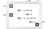
図5は、合成画像N2が液晶ディスプレイ200に表示された例を示す説明図である。この図5には、原画像データN1中に2つのマスク表示用マークMKa,MKbが含まれている場合の合成画像N2の表示例を示している。このように、原画像データN1中に2つのマスク表示用マークMKa,MKbが配置されている場合には、マスク情報INFから、2つのマスク表示用マークMKa,MKbのそれぞれについてマスク範囲データが読み込まれ、各マスク表示用マークMKa,MKbに対して、それぞれ、1箇所ずつ、マスク画像MIが表示される。
FIG. 5 is an explanatory diagram showing an example in which the composite image N2 is displayed on the
図6は、マスク表示用マークに傾きが生じている場合の表示例を示す説明図である。原画像データN1内のマスク表示用マークに、角度θの傾きが生じている場合には、その角度θに応じて、マスク範囲データの各座標が調整される。この結果、図6に示すように、合成画像N2中のマスク画像MIの位置および傾きも調整される。 FIG. 6 is an explanatory diagram illustrating a display example when the mask display mark is tilted. If the mask display mark in the original image data N1 has an inclination of the angle θ, the coordinates of the mask range data are adjusted according to the angle θ. As a result, as shown in FIG. 6, the position and inclination of the mask image MI in the composite image N2 are also adjusted.
図7は、原画像データ内に検出されたマスク表示用マークの大きさが本来の大きさと異なる場合の表示方法を示す図である。図7(a)には、マスク表示用マークの本来の大きさを示し、図7(b)には、光学ズームによってマスク表示用マークが2倍の大きさで原画像データ内から検出された例を示している。このように、マスク表示用マークが本来の大きさとは異なる大きさで検出された場合には、その拡大率(図7の場合には2倍)に応じて、マスク画像MIの表示位置と大きさとが調整される。 FIG. 7 is a diagram showing a display method when the size of the mask display mark detected in the original image data is different from the original size. FIG. 7A shows the original size of the mask display mark, and FIG. 7B shows that the mask display mark is detected in the original image data in the double size by the optical zoom. An example is shown. As described above, when the mask display mark is detected with a size different from the original size, the display position and the size of the mask image MI according to the enlargement ratio (twice in the case of FIG. 7). Sato is adjusted.
なお、原画像データ内のマスク表示用マークに傾きが生じており、かつ、マスク表示用マークが本来の大きさと異なる場合には、マスク画像MIに対して、図6と図7とに示した処理が同時に実行される。 When the mask display mark in the original image data is inclined and the mask display mark is different from the original size, the mask image MI is shown in FIG. 6 and FIG. Processing is performed simultaneously.
図8は、マスク消去用マークMKeが原画像データ内に検出された場合の表示例を示す図である。上記ステップS18において、マスク消去用マークMKeが原画像データN1内から検出された場合には、マーク検出部140から合成画像生成部160に対して、消去信号が出力される。この結果、図8に示すように、原画像データN1内に、マスク表示用マークMKa,MKbが存在していたとしても、マスク画像MIは原画像データN1に合成されず、画像出力部170あるいは画像符号化部180から原画像データN1がそのまま出力されることになる(ステップS16)。そのため、例えば、マスク画像MIが表示された状態で、マスク消去用マークMKeを資料ST上に後から配置した場合などには、これまで表示されていたマスク画像MIが消去され、液晶ディスプレイ200等には、資料STの内容がそのまま表示されることになる。
FIG. 8 is a diagram showing a display example when the mask erasing mark MKe is detected in the original image data. In step S18, when the mask erasing mark MKe is detected from the original image data N1, an erasing signal is output from the
以上で説明した本実施例の資料提示装置100によれば、マスク表示用マークを資料ST上に配置するだけで、予めマスク情報INFに登録しておいたマスク画像MIが原画像データに合成されて表示される。そのため、ユーザは、資料上の所望の範囲を容易にマスクすることができる。また、マスク画像MIの生成時に参照されるマスク情報INFには、マスクを行う範囲が、マスク表示用マークの存在位置からの相対座標によって記録されている。そのため、資料STが動いてしまったとしても、その資料STの動きに追従してマスク画像MIも表示画面上を移動する。この結果、ユーザがマスクしたい部分を的確にマスクすることが可能になる。さらに、本実施例では、マスク表示用マークの傾きと大きさと応じて、マスク画像MIの傾きや大きさも調整されるため、資料STがどのような状態で撮影されたとしても、ユーザがマスクしたい部分を的確にマスクすることができる。
According to the
また、本実施例では、資料ST上に、マスク消去用マークが配置されると、資料ST上にマスク表示用マークが配置されていたとしても、マスク画像MIが消去される。そのため、例えば、資料ST上にマスク表示用マークが印刷されている場合であっても、容易にマスク画像MIを消去することが可能になる。また、本実施例では、マスク消去用マークの位置や傾き、大きさにかかわらず、マスク消去用マークが原画像データ内から検出されれば、マスク画像MIを消去するため、マスク画像MIをより一層、容易に消去することが可能になる。 In this embodiment, when a mask erasing mark is arranged on the material ST, the mask image MI is erased even if a mask display mark is arranged on the material ST. Therefore, for example, even if a mask display mark is printed on the material ST, the mask image MI can be easily erased. In this embodiment, the mask image MI is erased when the mask erase mark is detected from the original image data regardless of the position, inclination, and size of the mask erase mark. It becomes possible to erase more easily.
C.変形例:
以上、本発明の一実施例について説明したが、本発明はこのような実施例に限定されず、その趣旨を逸脱しない範囲で種々の構成を採ることができる。例えば、以下のような変形が可能である。
C. Variations:
As mentioned above, although one Example of this invention was described, this invention is not limited to such an Example, A various structure can be taken in the range which does not deviate from the meaning. For example, the following modifications are possible.
・変形例1:
上述した実施例では、資料提示装置100に備えられた操作部103を用いて、マスク範囲データの登録を行うこととした。しかし、マスク範囲データの登録は、他の方法によって行うこととしてもよい。例えば、図2に示したフラッシュメモリ184を着脱自在のメモリカードとして構成すれば、コンピュータ等によって予めマスク範囲データを編集することが可能になる。また、USBインタフェース195を介して接続されたコンピュータによって、直接、マスク範囲データを編集可能としてもよい。
・ Modification 1:
In the above-described embodiment, the mask range data is registered using the
・変形例2:
マスク範囲データの登録は、他の方法によっても実現可能である。例えば、ユーザは、資料ST上に、予めマスク表示用マークを配置し、更に、マスクしたい範囲と同じ大きさの所定の色の用紙を、マスクしたい部分に載置する。この状態で、資料提示装置100は、撮影部120によって、この資料STを撮影し、マーク検出部140によって、マスク表示用マークと、上述した所定の色の範囲を検出する。こうして、マスク表示用マークと、所定の色の範囲を検出すると、マスク登録部182は、検出された所定の色の範囲を、同じく検出されたマスク表示用マークに対応付けてマスク情報INFに記録する。このような方法によってマスク範囲データを登録可能とすれば、ユーザは、容易にマスク範囲データを登録することが可能になる。
Registration of the mask range data can also be realized by other methods. For example, the user arranges a mask display mark in advance on the material ST, and further places a sheet of a predetermined color having the same size as the range to be masked on the portion to be masked. In this state, the
・変形例3:
上述した実施例では、マスク表示用マークとマスク画像MIとの間に、所定の間隔が設けられている例を示した。しかし、マスク画像MIは、マスク表示用マークに隣接して表示されることとしてもよい。こうすることにより、ユーザは、マスク画像MIを配置する位置を容易に指定することができる。また、この場合に、マスク表示用マークの図柄に応じて、マスクされる範囲が予め設定されていることとしてもよい。こうすることで、ユーザは、マスク表示用マークを使い分けることで、マスクを行う範囲を容易に指定することが可能になる。
・ Modification 3:
In the above-described embodiment, an example in which a predetermined interval is provided between the mask display mark and the mask image MI is shown. However, the mask image MI may be displayed adjacent to the mask display mark. In this way, the user can easily specify the position where the mask image MI is to be placed. In this case, the masked range may be set in advance according to the design of the mask display mark. In this way, the user can easily specify the masking range by using different mask display marks.
・変形例4:
上述した実施例では、マスク表示用マークとして、矩形の枠内にアルファベットが配置された図柄を示したが、マスク表示用マークをバーコード等によって構成することとしてもよい。そして、このバーコードに、マスク範囲データを記録しておくこととしてもよい。このようにすれば、フラッシュメモリ184にマスク範囲データが登録されていなくても、バーコードを解析することでマスクの範囲を決定することができる。
-Modification 4:
In the above-described embodiment, as a mask display mark, a design in which alphabets are arranged in a rectangular frame is shown. However, the mask display mark may be configured by a bar code or the like. Then, mask range data may be recorded on this barcode. In this way, even if the mask range data is not registered in the
・変形例5:
上述した実施例では、マスク処理用マークとして、マスク表示用マークとマスク消去用マークとを示したが、マスク処理用マークはこれらに限られず、マスクの合成に関する他の様々な処理を実行可能なマークを用意してもよい。例えば、マスク画像MI内に、予め定められた画像や映像を表示可能なマークを用意してもよい。また、マスク消去用マークとして、マスク画像MIの色が徐々に薄くなるようなアニメーションや、マスク画像MIが他の位置あるいは画面外に移動するアニメーションが行われるマークを用意してもよい。
Modification 5:
In the above-described embodiments, the mask display mark and the mask erasure mark are shown as the mask processing marks. However, the mask processing marks are not limited to these, and various other processes relating to mask composition can be performed. A mark may be prepared. For example, a mark capable of displaying a predetermined image or video may be prepared in the mask image MI. Further, as the mask erasing mark, an animation in which the color of the mask image MI gradually fades or a mark in which an animation in which the mask image MI moves to another position or outside the screen may be prepared.
・変形例6:
上述した実施例では、原画像データN1内にマスク消去用マークMKeが検出された場合には、すべてのマスク画像MIが消去されることとした。これに対して、例えば、マスク消去用マークMKeに最も近接したマスク画像MIのみが消去されることとしてもよい。また、マスク表示用マークが複数種類存在する場合には、それぞれのマスク表示用マークに対応するマスク消去用マークを用意してもよい。こうすることによって、消去したいマスク画像MIを容易に指定することが可能になる。
Modification 6:
In the embodiment described above, when the mask erasing mark MKe is detected in the original image data N1, all the mask images MI are erased. On the other hand, for example, only the mask image MI closest to the mask erasing mark MKe may be erased. When there are a plurality of types of mask display marks, mask erasure marks corresponding to the respective mask display marks may be prepared. By doing so, it becomes possible to easily specify the mask image MI to be erased.
・変形例7:
上述した実施例では、図4に示したマスク処理を、ASICにより構成されたマーク検出部140や、マスク画像生成部150、合成画像生成部160、画像出力部170、画像符号化部180によって実行することとした。これに対して、マスク処理は、CPUやRAM、ROMを備えるマイクロコンピュータによって、ソフトウェア的に実行されることとしてもよい。
Modification 7:
In the above-described embodiment, the mask processing shown in FIG. 4 is executed by the
・変形例8:
上述した実施例では、マスク表示用マークとして、矩形の枠内にアルファベットが配置されたマークを採用した。しかし、この図柄は任意であり、マスク表示用マークの位置と方向と大きさとが検出可能な図柄であればよい。また、マスク消去用マークの図柄も、適宜他の図柄を採用可能である。
-Modification 8:
In the embodiment described above, a mark in which alphabets are arranged in a rectangular frame is employed as a mask display mark. However, this symbol is arbitrary, and may be any symbol as long as the position, direction, and size of the mask display mark can be detected. In addition, other symbols can be adopted as appropriate for the mask erasing mark.
100…資料提示装置
102…本体
103…操作部
104…支柱
106…カメラヘッド
120…撮影部
130…フレームメモリ
140…マーク検出部
150…マスク画像生成部
160…合成画像生成部
170…画像出力部
180…画像符号化部
182…マスク登録部
184…フラッシュメモリ
190…映像出力端子
195…USBインタフェース
200…液晶ディスプレイ
ST…資料
INF…マスク情報
N1…原画像データ
N2…合成画像
MI…マスク画像
MK…マスク処理用マーク
MKa,MKb,MKc…マスク表示用マーク
MKe…マスク消去用マーク
DESCRIPTION OF
Claims (4)
被写体を撮影して原画像を生成する撮影部と、
所定の第1のマークが前記原画像内に含まれているか否かを解析し、前記第1のマークが前記原画像内に含まれている場合に、前記原画像内の前記第1のマークの存在位置を検出する検出部と、
前記原画像の少なくとも一部をマスクするマスク画像を前記原画像に合成するための合成位置と、前記第1のマークの存在位置との相対的な位置関係を記憶する記憶部と、
前記検出された存在位置と前記相対的な位置関係とに応じて前記合成位置を決定し、前記原画像内の前記決定された合成位置に前記マスク画像を合成して合成画像を生成する合成画像生成部と、
前記合成画像を出力する出力部と
を備え、
前記検出部は、前記第1のマークが前記原画像内に含まれている場合に、更に、前記第1のマークの傾きを検出し、
前記合成画像生成部は、前記検出された傾きに応じて、前記合成位置と前記マスク画像の傾きとを調整する
資料提示装置。 A data presentation device,
A shooting unit for shooting an object and generating an original image;
It is analyzed whether or not a predetermined first mark is included in the original image, and when the first mark is included in the original image, the first mark in the original image A detection unit for detecting the location of
A storage unit that stores a relative positional relationship between a combining position for combining a mask image that masks at least a part of the original image with the original image, and an existing position of the first mark;
A composite image that determines the composite position according to the detected presence position and the relative positional relationship, and generates a composite image by combining the mask image with the determined composite position in the original image. A generator,
An output unit for outputting the composite image;
With
The detection unit further detects an inclination of the first mark when the first mark is included in the original image;
The composite image generating unit adjusts the composite position and the inclination of the mask image according to the detected inclination.
前記検出部は、前記第1のマークが前記原画像内に含まれている場合に、更に、前記第1のマークの大きさを検出し、
前記合成画像生成部は、前記検出された大きさに応じて、前記合成位置と前記マスク画像の大きさとを調整する
資料提示装置。 The material presentation device according to claim 1 ,
The detection unit further detects the size of the first mark when the first mark is included in the original image;
The composite image generating unit adjusts the composite position and the size of the mask image according to the detected size.
被写体を撮影して原画像を生成する撮影部と、
所定の第1のマークが前記原画像内に含まれているか否かを解析し、前記第1のマークが前記原画像内に含まれている場合に、前記原画像内の前記第1のマークの存在位置を検出する検出部と、
前記原画像の少なくとも一部をマスクするマスク画像を前記原画像に合成するための合成位置と、前記第1のマークの存在位置との相対的な位置関係を記憶する記憶部と、
前記検出された存在位置と前記相対的な位置関係とに応じて前記合成位置を決定し、前記原画像内の前記決定された合成位置に前記マスク画像を合成して合成画像を生成する合成画像生成部と、
前記合成画像を出力する出力部と
を備え、
前記検出部は、更に、前記第1のマークとは異なる第2のマークが前記原画像内に含まれているか否かを解析し、
前記合成画像生成部は、前記第2のマークが前記原画像内に含まれている場合に、前記合成に関する所定の処理を実行する
資料提示装置。 A data presentation device,
A shooting unit for shooting an object and generating an original image;
It is analyzed whether or not a predetermined first mark is included in the original image, and when the first mark is included in the original image, the first mark in the original image A detection unit for detecting the location of
A storage unit that stores a relative positional relationship between a combining position for combining a mask image that masks at least a part of the original image with the original image, and an existing position of the first mark;
A composite image that determines the composite position according to the detected presence position and the relative positional relationship, and generates a composite image by combining the mask image with the determined composite position in the original image. A generator,
An output unit for outputting the composite image;
With
The detection unit further analyzes whether or not a second mark different from the first mark is included in the original image,
The said composite image production | generation part is a data presentation apparatus which performs the predetermined | prescribed process regarding the said composite, when the said 2nd mark is contained in the said original image.
前記合成画像生成部は、前記第2のマークが前記原画像内に含まれている場合に、前記所定の処理として、前記合成画像から前記マスク画像を消去する処理を実行する
資料提示装置。 The material presentation device according to claim 3 ,
The said composite image production | generation part is a data presentation apparatus which performs the process which erase | eliminates the said mask image from the said composite image as said predetermined | prescribed process, when the said 2nd mark is contained in the said original image.
Priority Applications (3)
| Application Number | Priority Date | Filing Date | Title |
|---|---|---|---|
| JP2009174855A JP5443085B2 (en) | 2009-07-28 | 2009-07-28 | Document presentation device |
| GB1012540A GB2472307A (en) | 2009-07-28 | 2010-07-26 | Document camera presentation device with markers placed on document to mask selected areas |
| US12/844,200 US8582920B2 (en) | 2009-07-28 | 2010-07-27 | Presentation device |
Applications Claiming Priority (1)
| Application Number | Priority Date | Filing Date | Title |
|---|---|---|---|
| JP2009174855A JP5443085B2 (en) | 2009-07-28 | 2009-07-28 | Document presentation device |
Publications (3)
| Publication Number | Publication Date |
|---|---|
| JP2011030031A JP2011030031A (en) | 2011-02-10 |
| JP2011030031A5 JP2011030031A5 (en) | 2012-08-09 |
| JP5443085B2 true JP5443085B2 (en) | 2014-03-19 |
Family
ID=42752815
Family Applications (1)
| Application Number | Title | Priority Date | Filing Date |
|---|---|---|---|
| JP2009174855A Active JP5443085B2 (en) | 2009-07-28 | 2009-07-28 | Document presentation device |
Country Status (3)
| Country | Link |
|---|---|
| US (1) | US8582920B2 (en) |
| JP (1) | JP5443085B2 (en) |
| GB (1) | GB2472307A (en) |
Families Citing this family (6)
| Publication number | Priority date | Publication date | Assignee | Title |
|---|---|---|---|---|
| JP2014112781A (en) * | 2012-12-05 | 2014-06-19 | Kyoiku Dojinsha:Kk | Image projection device |
| JP5997601B2 (en) * | 2012-12-17 | 2016-09-28 | 株式会社Pfu | Imaging system |
| US9891438B2 (en) | 2014-04-30 | 2018-02-13 | Freedom Scientific, Inc. | System and method for processing a video signal with reduced latency |
| US10462381B2 (en) | 2014-04-30 | 2019-10-29 | Freedom Scientific, Inc. | System and method for processing a video signal with reduced latency |
| JP6464676B2 (en) * | 2014-11-04 | 2019-02-06 | 富士通株式会社 | Display control program, display control method, and information processing apparatus |
| CN106547047A (en) * | 2017-01-24 | 2017-03-29 | 合肥京东方光电科技有限公司 | A kind of light guide plate, backlight module and display device |
Family Cites Families (24)
| Publication number | Priority date | Publication date | Assignee | Title |
|---|---|---|---|---|
| US5098817A (en) * | 1989-03-10 | 1992-03-24 | Voorhees Scott W | Highlighting for photocopiers and facsimile machines |
| US5465163A (en) * | 1991-03-18 | 1995-11-07 | Canon Kabushiki Kaisha | Image processing method and apparatus for processing oversized original images and for synthesizing multiple images |
| JPH08307651A (en) * | 1995-05-08 | 1996-11-22 | Canon Inc | Facsimile equipment |
| US20030228565A1 (en) * | 2000-04-26 | 2003-12-11 | Cytokinetics, Inc. | Method and apparatus for predictive cellular bioinformatics |
| JP3478192B2 (en) * | 1999-08-20 | 2003-12-15 | 日本電気株式会社 | Screen superimposed display type information input / output device |
| US7149262B1 (en) * | 2000-07-06 | 2006-12-12 | The Trustees Of Columbia University In The City Of New York | Method and apparatus for enhancing data resolution |
| JP4300503B2 (en) | 2000-09-18 | 2009-07-22 | 日本ビクター株式会社 | Document presentation device |
| US8423294B2 (en) * | 2001-09-18 | 2013-04-16 | Pathogenetix, Inc. | High resolution linear analysis of polymers |
| JP3852585B2 (en) * | 2002-01-18 | 2006-11-29 | オムロンエンタテインメント株式会社 | Photo sticker vending method and apparatus |
| JP2004048634A (en) * | 2002-05-13 | 2004-02-12 | Fuji Photo Optical Co Ltd | Document camera instrument |
| JP3813544B2 (en) | 2002-06-17 | 2006-08-23 | フジノン株式会社 | Presentation system |
| JP2004070023A (en) * | 2002-08-07 | 2004-03-04 | Fuji Photo Optical Co Ltd | Document presenting device |
| JP2004228806A (en) * | 2003-01-21 | 2004-08-12 | Fuji Photo Optical Co Ltd | Data presentation apparatus |
| JP4344196B2 (en) | 2003-08-21 | 2009-10-14 | フジノン株式会社 | Document presentation device |
| JP2005128506A (en) * | 2003-09-30 | 2005-05-19 | Sanyo Electric Co Ltd | Portable projector |
| US7394053B2 (en) * | 2004-09-09 | 2008-07-01 | Beth Israel Deaconess Medical Center, Inc. | Systems and methods for multi-modal imaging having a spatial relationship in three dimensions between first and second image data |
| US20060215232A1 (en) * | 2005-03-23 | 2006-09-28 | Jakob Ziv-El | Method and apparatus for processing selected images on image reproduction machines |
| JP2006308709A (en) * | 2005-04-27 | 2006-11-09 | Tohoku Univ | Microscope stage, and focal position measuring instrument and confocal microscope system |
| US20080177640A1 (en) * | 2005-05-09 | 2008-07-24 | Salih Burak Gokturk | System and method for using image analysis and search in e-commerce |
| US7657126B2 (en) * | 2005-05-09 | 2010-02-02 | Like.Com | System and method for search portions of objects in images and features thereof |
| JP4574473B2 (en) * | 2005-07-11 | 2010-11-04 | キヤノン株式会社 | Information processing apparatus and method |
| JP4678857B2 (en) * | 2005-12-28 | 2011-04-27 | キヤノン株式会社 | Image processing apparatus, image processing method, and program |
| JP4926533B2 (en) * | 2006-05-02 | 2012-05-09 | キヤノン株式会社 | Moving image processing apparatus, moving image processing method, and program |
| TW200840354A (en) * | 2007-03-23 | 2008-10-01 | Avermedia Information Inc | Method for image displaying for document projector |
-
2009
- 2009-07-28 JP JP2009174855A patent/JP5443085B2/en active Active
-
2010
- 2010-07-26 GB GB1012540A patent/GB2472307A/en not_active Withdrawn
- 2010-07-27 US US12/844,200 patent/US8582920B2/en active Active
Also Published As
| Publication number | Publication date |
|---|---|
| US8582920B2 (en) | 2013-11-12 |
| JP2011030031A (en) | 2011-02-10 |
| US20110026769A1 (en) | 2011-02-03 |
| GB2472307A (en) | 2011-02-02 |
| GB201012540D0 (en) | 2010-09-08 |
Similar Documents
| Publication | Publication Date | Title |
|---|---|---|
| JP5443085B2 (en) | Document presentation device | |
| US20060222260A1 (en) | Image capture apparatus, image processing method for captured image, and recording medium | |
| KR101457813B1 (en) | Print target data processing apparatus, print target data processing method, and storage medium | |
| JP2007266667A (en) | Camera-equipped mobile apparatus, control method thereof, and photographing support method thereof | |
| JP2006236195A (en) | Presentation control device | |
| US20130169671A1 (en) | Projector and method for controlling image display of the same | |
| KR20090022710A (en) | Digital photographing apparatus, method for controlling the same, and recording medium storing program to implement the method | |
| JP2007079894A (en) | Image processor, processing method and program | |
| JP5024028B2 (en) | Image conversion apparatus, image providing system, photographing / editing apparatus, image conversion method, image conversion program, and recording medium recording the program | |
| JP2004199299A (en) | Handwritten information recording method and projection recording device | |
| US20140240580A1 (en) | Method and apparatus of displaying portrait on display | |
| JP2010072813A (en) | Image processing device and image processing program | |
| JP2009089220A (en) | Imaging apparatus | |
| JP2004239967A (en) | Projector | |
| JP5061696B2 (en) | Projection apparatus, projection control method, and program | |
| JP2006184415A (en) | Image processor, image processing program, and image processing method | |
| JP2006054824A (en) | Projection image display device | |
| JP2009060564A (en) | Conference system | |
| JP5230558B2 (en) | Document presentation device | |
| JP5292210B2 (en) | Document presentation device | |
| JP5218687B2 (en) | Image conversion apparatus, image providing system, photographing / editing apparatus, image conversion method, image conversion program, and recording medium recording the program | |
| JP2013131811A (en) | Image display device | |
| JP5696525B2 (en) | Imaging apparatus, imaging method, and program | |
| JP2008301459A (en) | Conference system | |
| JP2016039513A (en) | Image generation apparatus, image generation method, and program |
Legal Events
| Date | Code | Title | Description |
|---|---|---|---|
| A521 | Request for written amendment filed |
Free format text: JAPANESE INTERMEDIATE CODE: A523 Effective date: 20120627 |
|
| A621 | Written request for application examination |
Free format text: JAPANESE INTERMEDIATE CODE: A621 Effective date: 20120627 |
|
| A131 | Notification of reasons for refusal |
Free format text: JAPANESE INTERMEDIATE CODE: A131 Effective date: 20130521 |
|
| A131 | Notification of reasons for refusal |
Free format text: JAPANESE INTERMEDIATE CODE: A131 Effective date: 20130917 |
|
| A521 | Request for written amendment filed |
Free format text: JAPANESE INTERMEDIATE CODE: A523 Effective date: 20131118 |
|
| TRDD | Decision of grant or rejection written | ||
| A01 | Written decision to grant a patent or to grant a registration (utility model) |
Free format text: JAPANESE INTERMEDIATE CODE: A01 Effective date: 20131203 |
|
| A61 | First payment of annual fees (during grant procedure) |
Free format text: JAPANESE INTERMEDIATE CODE: A61 Effective date: 20131219 |
|
| R150 | Certificate of patent or registration of utility model |
Ref document number: 5443085 Country of ref document: JP Free format text: JAPANESE INTERMEDIATE CODE: R150 Free format text: JAPANESE INTERMEDIATE CODE: R150 |
|
| R250 | Receipt of annual fees |
Free format text: JAPANESE INTERMEDIATE CODE: R250 |
|
| R250 | Receipt of annual fees |
Free format text: JAPANESE INTERMEDIATE CODE: R250 |
|
| S531 | Written request for registration of change of domicile |
Free format text: JAPANESE INTERMEDIATE CODE: R313531 |
|
| R350 | Written notification of registration of transfer |
Free format text: JAPANESE INTERMEDIATE CODE: R350 |
|
| R250 | Receipt of annual fees |
Free format text: JAPANESE INTERMEDIATE CODE: R250 |
|
| R250 | Receipt of annual fees |
Free format text: JAPANESE INTERMEDIATE CODE: R250 |
|
| S111 | Request for change of ownership or part of ownership |
Free format text: JAPANESE INTERMEDIATE CODE: R313111 |
|
| R350 | Written notification of registration of transfer |
Free format text: JAPANESE INTERMEDIATE CODE: R350 |
|
| R250 | Receipt of annual fees |
Free format text: JAPANESE INTERMEDIATE CODE: R250 |
|
| R250 | Receipt of annual fees |
Free format text: JAPANESE INTERMEDIATE CODE: R250 |
|
| R250 | Receipt of annual fees |
Free format text: JAPANESE INTERMEDIATE CODE: R250 |