JP5437380B2 - Twin clutch hybrid transmission - Google Patents
Twin clutch hybrid transmission Download PDFInfo
- Publication number
- JP5437380B2 JP5437380B2 JP2011529846A JP2011529846A JP5437380B2 JP 5437380 B2 JP5437380 B2 JP 5437380B2 JP 2011529846 A JP2011529846 A JP 2011529846A JP 2011529846 A JP2011529846 A JP 2011529846A JP 5437380 B2 JP5437380 B2 JP 5437380B2
- Authority
- JP
- Japan
- Prior art keywords
- numbered
- odd
- transmission
- gear train
- speed
- Prior art date
- Legal status (The legal status is an assumption and is not a legal conclusion. Google has not performed a legal analysis and makes no representation as to the accuracy of the status listed.)
- Active
Links
- 230000005540 biological transmission Effects 0.000 title claims description 606
- 230000007246 mechanism Effects 0.000 claims description 162
- 230000001360 synchronised effect Effects 0.000 claims description 81
- 230000001172 regenerating effect Effects 0.000 claims description 24
- 230000008859 change Effects 0.000 claims description 13
- 230000008878 coupling Effects 0.000 claims description 12
- 238000010168 coupling process Methods 0.000 claims description 12
- 238000005859 coupling reaction Methods 0.000 claims description 12
- 230000001133 acceleration Effects 0.000 claims description 10
- 238000002360 preparation method Methods 0.000 description 25
- 230000008929 regeneration Effects 0.000 description 14
- 238000011069 regeneration method Methods 0.000 description 14
- 230000004048 modification Effects 0.000 description 5
- 238000012986 modification Methods 0.000 description 5
- 238000010586 diagram Methods 0.000 description 2
- 238000005516 engineering process Methods 0.000 description 2
- 230000007935 neutral effect Effects 0.000 description 2
- 238000005381 potential energy Methods 0.000 description 2
- 230000009194 climbing Effects 0.000 description 1
- 238000010276 construction Methods 0.000 description 1
- 238000001816 cooling Methods 0.000 description 1
- 230000007423 decrease Effects 0.000 description 1
- 238000006073 displacement reaction Methods 0.000 description 1
- 230000000694 effects Effects 0.000 description 1
- 239000000446 fuel Substances 0.000 description 1
- 230000006870 function Effects 0.000 description 1
- 230000020169 heat generation Effects 0.000 description 1
- 230000006872 improvement Effects 0.000 description 1
- 238000000034 method Methods 0.000 description 1
- 238000011084 recovery Methods 0.000 description 1
- 239000007858 starting material Substances 0.000 description 1
Images


Classifications
-
- F—MECHANICAL ENGINEERING; LIGHTING; HEATING; WEAPONS; BLASTING
- F16—ENGINEERING ELEMENTS AND UNITS; GENERAL MEASURES FOR PRODUCING AND MAINTAINING EFFECTIVE FUNCTIONING OF MACHINES OR INSTALLATIONS; THERMAL INSULATION IN GENERAL
- F16H—GEARING
- F16H3/00—Toothed gearings for conveying rotary motion with variable gear ratio or for reversing rotary motion
- F16H3/006—Toothed gearings for conveying rotary motion with variable gear ratio or for reversing rotary motion power being selectively transmitted by either one of the parallel flow paths
-
- B—PERFORMING OPERATIONS; TRANSPORTING
- B60—VEHICLES IN GENERAL
- B60K—ARRANGEMENT OR MOUNTING OF PROPULSION UNITS OR OF TRANSMISSIONS IN VEHICLES; ARRANGEMENT OR MOUNTING OF PLURAL DIVERSE PRIME-MOVERS IN VEHICLES; AUXILIARY DRIVES FOR VEHICLES; INSTRUMENTATION OR DASHBOARDS FOR VEHICLES; ARRANGEMENTS IN CONNECTION WITH COOLING, AIR INTAKE, GAS EXHAUST OR FUEL SUPPLY OF PROPULSION UNITS IN VEHICLES
- B60K6/00—Arrangement or mounting of plural diverse prime-movers for mutual or common propulsion, e.g. hybrid propulsion systems comprising electric motors and internal combustion engines ; Control systems therefor, i.e. systems controlling two or more prime movers, or controlling one of these prime movers and any of the transmission, drive or drive units Informative references: mechanical gearings with secondary electric drive F16H3/72; arrangements for handling mechanical energy structurally associated with the dynamo-electric machine H02K7/00; machines comprising structurally interrelated motor and generator parts H02K51/00; dynamo-electric machines not otherwise provided for in H02K see H02K99/00
- B60K6/20—Arrangement or mounting of plural diverse prime-movers for mutual or common propulsion, e.g. hybrid propulsion systems comprising electric motors and internal combustion engines ; Control systems therefor, i.e. systems controlling two or more prime movers, or controlling one of these prime movers and any of the transmission, drive or drive units Informative references: mechanical gearings with secondary electric drive F16H3/72; arrangements for handling mechanical energy structurally associated with the dynamo-electric machine H02K7/00; machines comprising structurally interrelated motor and generator parts H02K51/00; dynamo-electric machines not otherwise provided for in H02K see H02K99/00 the prime-movers consisting of electric motors and internal combustion engines, e.g. HEVs
- B60K6/42—Arrangement or mounting of plural diverse prime-movers for mutual or common propulsion, e.g. hybrid propulsion systems comprising electric motors and internal combustion engines ; Control systems therefor, i.e. systems controlling two or more prime movers, or controlling one of these prime movers and any of the transmission, drive or drive units Informative references: mechanical gearings with secondary electric drive F16H3/72; arrangements for handling mechanical energy structurally associated with the dynamo-electric machine H02K7/00; machines comprising structurally interrelated motor and generator parts H02K51/00; dynamo-electric machines not otherwise provided for in H02K see H02K99/00 the prime-movers consisting of electric motors and internal combustion engines, e.g. HEVs characterised by the architecture of the hybrid electric vehicle
- B60K6/44—Series-parallel type
- B60K6/442—Series-parallel switching type
-
- B—PERFORMING OPERATIONS; TRANSPORTING
- B60—VEHICLES IN GENERAL
- B60K—ARRANGEMENT OR MOUNTING OF PROPULSION UNITS OR OF TRANSMISSIONS IN VEHICLES; ARRANGEMENT OR MOUNTING OF PLURAL DIVERSE PRIME-MOVERS IN VEHICLES; AUXILIARY DRIVES FOR VEHICLES; INSTRUMENTATION OR DASHBOARDS FOR VEHICLES; ARRANGEMENTS IN CONNECTION WITH COOLING, AIR INTAKE, GAS EXHAUST OR FUEL SUPPLY OF PROPULSION UNITS IN VEHICLES
- B60K6/00—Arrangement or mounting of plural diverse prime-movers for mutual or common propulsion, e.g. hybrid propulsion systems comprising electric motors and internal combustion engines ; Control systems therefor, i.e. systems controlling two or more prime movers, or controlling one of these prime movers and any of the transmission, drive or drive units Informative references: mechanical gearings with secondary electric drive F16H3/72; arrangements for handling mechanical energy structurally associated with the dynamo-electric machine H02K7/00; machines comprising structurally interrelated motor and generator parts H02K51/00; dynamo-electric machines not otherwise provided for in H02K see H02K99/00
- B60K6/20—Arrangement or mounting of plural diverse prime-movers for mutual or common propulsion, e.g. hybrid propulsion systems comprising electric motors and internal combustion engines ; Control systems therefor, i.e. systems controlling two or more prime movers, or controlling one of these prime movers and any of the transmission, drive or drive units Informative references: mechanical gearings with secondary electric drive F16H3/72; arrangements for handling mechanical energy structurally associated with the dynamo-electric machine H02K7/00; machines comprising structurally interrelated motor and generator parts H02K51/00; dynamo-electric machines not otherwise provided for in H02K see H02K99/00 the prime-movers consisting of electric motors and internal combustion engines, e.g. HEVs
- B60K6/42—Arrangement or mounting of plural diverse prime-movers for mutual or common propulsion, e.g. hybrid propulsion systems comprising electric motors and internal combustion engines ; Control systems therefor, i.e. systems controlling two or more prime movers, or controlling one of these prime movers and any of the transmission, drive or drive units Informative references: mechanical gearings with secondary electric drive F16H3/72; arrangements for handling mechanical energy structurally associated with the dynamo-electric machine H02K7/00; machines comprising structurally interrelated motor and generator parts H02K51/00; dynamo-electric machines not otherwise provided for in H02K see H02K99/00 the prime-movers consisting of electric motors and internal combustion engines, e.g. HEVs characterised by the architecture of the hybrid electric vehicle
- B60K6/48—Parallel type
-
- B—PERFORMING OPERATIONS; TRANSPORTING
- B60—VEHICLES IN GENERAL
- B60K—ARRANGEMENT OR MOUNTING OF PROPULSION UNITS OR OF TRANSMISSIONS IN VEHICLES; ARRANGEMENT OR MOUNTING OF PLURAL DIVERSE PRIME-MOVERS IN VEHICLES; AUXILIARY DRIVES FOR VEHICLES; INSTRUMENTATION OR DASHBOARDS FOR VEHICLES; ARRANGEMENTS IN CONNECTION WITH COOLING, AIR INTAKE, GAS EXHAUST OR FUEL SUPPLY OF PROPULSION UNITS IN VEHICLES
- B60K6/00—Arrangement or mounting of plural diverse prime-movers for mutual or common propulsion, e.g. hybrid propulsion systems comprising electric motors and internal combustion engines ; Control systems therefor, i.e. systems controlling two or more prime movers, or controlling one of these prime movers and any of the transmission, drive or drive units Informative references: mechanical gearings with secondary electric drive F16H3/72; arrangements for handling mechanical energy structurally associated with the dynamo-electric machine H02K7/00; machines comprising structurally interrelated motor and generator parts H02K51/00; dynamo-electric machines not otherwise provided for in H02K see H02K99/00
- B60K6/20—Arrangement or mounting of plural diverse prime-movers for mutual or common propulsion, e.g. hybrid propulsion systems comprising electric motors and internal combustion engines ; Control systems therefor, i.e. systems controlling two or more prime movers, or controlling one of these prime movers and any of the transmission, drive or drive units Informative references: mechanical gearings with secondary electric drive F16H3/72; arrangements for handling mechanical energy structurally associated with the dynamo-electric machine H02K7/00; machines comprising structurally interrelated motor and generator parts H02K51/00; dynamo-electric machines not otherwise provided for in H02K see H02K99/00 the prime-movers consisting of electric motors and internal combustion engines, e.g. HEVs
- B60K6/50—Architecture of the driveline characterised by arrangement or kind of transmission units
- B60K6/54—Transmission for changing ratio
- B60K6/547—Transmission for changing ratio the transmission being a stepped gearing
-
- B—PERFORMING OPERATIONS; TRANSPORTING
- B60—VEHICLES IN GENERAL
- B60L—PROPULSION OF ELECTRICALLY-PROPELLED VEHICLES; SUPPLYING ELECTRIC POWER FOR AUXILIARY EQUIPMENT OF ELECTRICALLY-PROPELLED VEHICLES; ELECTRODYNAMIC BRAKE SYSTEMS FOR VEHICLES IN GENERAL; MAGNETIC SUSPENSION OR LEVITATION FOR VEHICLES; MONITORING OPERATING VARIABLES OF ELECTRICALLY-PROPELLED VEHICLES; ELECTRIC SAFETY DEVICES FOR ELECTRICALLY-PROPELLED VEHICLES
- B60L15/00—Methods, circuits, or devices for controlling the traction-motor speed of electrically-propelled vehicles
- B60L15/20—Methods, circuits, or devices for controlling the traction-motor speed of electrically-propelled vehicles for control of the vehicle or its driving motor to achieve a desired performance, e.g. speed, torque, programmed variation of speed
-
- B—PERFORMING OPERATIONS; TRANSPORTING
- B60—VEHICLES IN GENERAL
- B60L—PROPULSION OF ELECTRICALLY-PROPELLED VEHICLES; SUPPLYING ELECTRIC POWER FOR AUXILIARY EQUIPMENT OF ELECTRICALLY-PROPELLED VEHICLES; ELECTRODYNAMIC BRAKE SYSTEMS FOR VEHICLES IN GENERAL; MAGNETIC SUSPENSION OR LEVITATION FOR VEHICLES; MONITORING OPERATING VARIABLES OF ELECTRICALLY-PROPELLED VEHICLES; ELECTRIC SAFETY DEVICES FOR ELECTRICALLY-PROPELLED VEHICLES
- B60L50/00—Electric propulsion with power supplied within the vehicle
- B60L50/10—Electric propulsion with power supplied within the vehicle using propulsion power supplied by engine-driven generators, e.g. generators driven by combustion engines
- B60L50/16—Electric propulsion with power supplied within the vehicle using propulsion power supplied by engine-driven generators, e.g. generators driven by combustion engines with provision for separate direct mechanical propulsion
-
- B—PERFORMING OPERATIONS; TRANSPORTING
- B60—VEHICLES IN GENERAL
- B60L—PROPULSION OF ELECTRICALLY-PROPELLED VEHICLES; SUPPLYING ELECTRIC POWER FOR AUXILIARY EQUIPMENT OF ELECTRICALLY-PROPELLED VEHICLES; ELECTRODYNAMIC BRAKE SYSTEMS FOR VEHICLES IN GENERAL; MAGNETIC SUSPENSION OR LEVITATION FOR VEHICLES; MONITORING OPERATING VARIABLES OF ELECTRICALLY-PROPELLED VEHICLES; ELECTRIC SAFETY DEVICES FOR ELECTRICALLY-PROPELLED VEHICLES
- B60L7/00—Electrodynamic brake systems for vehicles in general
- B60L7/10—Dynamic electric regenerative braking
- B60L7/14—Dynamic electric regenerative braking for vehicles propelled by ac motors
-
- B—PERFORMING OPERATIONS; TRANSPORTING
- B60—VEHICLES IN GENERAL
- B60W—CONJOINT CONTROL OF VEHICLE SUB-UNITS OF DIFFERENT TYPE OR DIFFERENT FUNCTION; CONTROL SYSTEMS SPECIALLY ADAPTED FOR HYBRID VEHICLES; ROAD VEHICLE DRIVE CONTROL SYSTEMS FOR PURPOSES NOT RELATED TO THE CONTROL OF A PARTICULAR SUB-UNIT
- B60W10/00—Conjoint control of vehicle sub-units of different type or different function
- B60W10/10—Conjoint control of vehicle sub-units of different type or different function including control of change-speed gearings
- B60W10/11—Stepped gearings
- B60W10/113—Stepped gearings with two input flow paths, e.g. double clutch transmission selection of one of the torque flow paths by the corresponding input clutch
-
- B—PERFORMING OPERATIONS; TRANSPORTING
- B60—VEHICLES IN GENERAL
- B60K—ARRANGEMENT OR MOUNTING OF PROPULSION UNITS OR OF TRANSMISSIONS IN VEHICLES; ARRANGEMENT OR MOUNTING OF PLURAL DIVERSE PRIME-MOVERS IN VEHICLES; AUXILIARY DRIVES FOR VEHICLES; INSTRUMENTATION OR DASHBOARDS FOR VEHICLES; ARRANGEMENTS IN CONNECTION WITH COOLING, AIR INTAKE, GAS EXHAUST OR FUEL SUPPLY OF PROPULSION UNITS IN VEHICLES
- B60K6/00—Arrangement or mounting of plural diverse prime-movers for mutual or common propulsion, e.g. hybrid propulsion systems comprising electric motors and internal combustion engines ; Control systems therefor, i.e. systems controlling two or more prime movers, or controlling one of these prime movers and any of the transmission, drive or drive units Informative references: mechanical gearings with secondary electric drive F16H3/72; arrangements for handling mechanical energy structurally associated with the dynamo-electric machine H02K7/00; machines comprising structurally interrelated motor and generator parts H02K51/00; dynamo-electric machines not otherwise provided for in H02K see H02K99/00
- B60K6/20—Arrangement or mounting of plural diverse prime-movers for mutual or common propulsion, e.g. hybrid propulsion systems comprising electric motors and internal combustion engines ; Control systems therefor, i.e. systems controlling two or more prime movers, or controlling one of these prime movers and any of the transmission, drive or drive units Informative references: mechanical gearings with secondary electric drive F16H3/72; arrangements for handling mechanical energy structurally associated with the dynamo-electric machine H02K7/00; machines comprising structurally interrelated motor and generator parts H02K51/00; dynamo-electric machines not otherwise provided for in H02K see H02K99/00 the prime-movers consisting of electric motors and internal combustion engines, e.g. HEVs
- B60K6/42—Arrangement or mounting of plural diverse prime-movers for mutual or common propulsion, e.g. hybrid propulsion systems comprising electric motors and internal combustion engines ; Control systems therefor, i.e. systems controlling two or more prime movers, or controlling one of these prime movers and any of the transmission, drive or drive units Informative references: mechanical gearings with secondary electric drive F16H3/72; arrangements for handling mechanical energy structurally associated with the dynamo-electric machine H02K7/00; machines comprising structurally interrelated motor and generator parts H02K51/00; dynamo-electric machines not otherwise provided for in H02K see H02K99/00 the prime-movers consisting of electric motors and internal combustion engines, e.g. HEVs characterised by the architecture of the hybrid electric vehicle
- B60K6/48—Parallel type
- B60K2006/4825—Electric machine connected or connectable to gearbox input shaft
-
- B—PERFORMING OPERATIONS; TRANSPORTING
- B60—VEHICLES IN GENERAL
- B60L—PROPULSION OF ELECTRICALLY-PROPELLED VEHICLES; SUPPLYING ELECTRIC POWER FOR AUXILIARY EQUIPMENT OF ELECTRICALLY-PROPELLED VEHICLES; ELECTRODYNAMIC BRAKE SYSTEMS FOR VEHICLES IN GENERAL; MAGNETIC SUSPENSION OR LEVITATION FOR VEHICLES; MONITORING OPERATING VARIABLES OF ELECTRICALLY-PROPELLED VEHICLES; ELECTRIC SAFETY DEVICES FOR ELECTRICALLY-PROPELLED VEHICLES
- B60L2200/00—Type of vehicles
- B60L2200/26—Rail vehicles
-
- B—PERFORMING OPERATIONS; TRANSPORTING
- B60—VEHICLES IN GENERAL
- B60L—PROPULSION OF ELECTRICALLY-PROPELLED VEHICLES; SUPPLYING ELECTRIC POWER FOR AUXILIARY EQUIPMENT OF ELECTRICALLY-PROPELLED VEHICLES; ELECTRODYNAMIC BRAKE SYSTEMS FOR VEHICLES IN GENERAL; MAGNETIC SUSPENSION OR LEVITATION FOR VEHICLES; MONITORING OPERATING VARIABLES OF ELECTRICALLY-PROPELLED VEHICLES; ELECTRIC SAFETY DEVICES FOR ELECTRICALLY-PROPELLED VEHICLES
- B60L2210/00—Converter types
- B60L2210/40—DC to AC converters
-
- B—PERFORMING OPERATIONS; TRANSPORTING
- B60—VEHICLES IN GENERAL
- B60L—PROPULSION OF ELECTRICALLY-PROPELLED VEHICLES; SUPPLYING ELECTRIC POWER FOR AUXILIARY EQUIPMENT OF ELECTRICALLY-PROPELLED VEHICLES; ELECTRODYNAMIC BRAKE SYSTEMS FOR VEHICLES IN GENERAL; MAGNETIC SUSPENSION OR LEVITATION FOR VEHICLES; MONITORING OPERATING VARIABLES OF ELECTRICALLY-PROPELLED VEHICLES; ELECTRIC SAFETY DEVICES FOR ELECTRICALLY-PROPELLED VEHICLES
- B60L2240/00—Control parameters of input or output; Target parameters
- B60L2240/40—Drive Train control parameters
- B60L2240/42—Drive Train control parameters related to electric machines
- B60L2240/423—Torque
-
- B—PERFORMING OPERATIONS; TRANSPORTING
- B60—VEHICLES IN GENERAL
- B60L—PROPULSION OF ELECTRICALLY-PROPELLED VEHICLES; SUPPLYING ELECTRIC POWER FOR AUXILIARY EQUIPMENT OF ELECTRICALLY-PROPELLED VEHICLES; ELECTRODYNAMIC BRAKE SYSTEMS FOR VEHICLES IN GENERAL; MAGNETIC SUSPENSION OR LEVITATION FOR VEHICLES; MONITORING OPERATING VARIABLES OF ELECTRICALLY-PROPELLED VEHICLES; ELECTRIC SAFETY DEVICES FOR ELECTRICALLY-PROPELLED VEHICLES
- B60L2240/00—Control parameters of input or output; Target parameters
- B60L2240/40—Drive Train control parameters
- B60L2240/44—Drive Train control parameters related to combustion engines
- B60L2240/443—Torque
-
- B—PERFORMING OPERATIONS; TRANSPORTING
- B60—VEHICLES IN GENERAL
- B60L—PROPULSION OF ELECTRICALLY-PROPELLED VEHICLES; SUPPLYING ELECTRIC POWER FOR AUXILIARY EQUIPMENT OF ELECTRICALLY-PROPELLED VEHICLES; ELECTRODYNAMIC BRAKE SYSTEMS FOR VEHICLES IN GENERAL; MAGNETIC SUSPENSION OR LEVITATION FOR VEHICLES; MONITORING OPERATING VARIABLES OF ELECTRICALLY-PROPELLED VEHICLES; ELECTRIC SAFETY DEVICES FOR ELECTRICALLY-PROPELLED VEHICLES
- B60L2240/00—Control parameters of input or output; Target parameters
- B60L2240/40—Drive Train control parameters
- B60L2240/50—Drive Train control parameters related to clutches
- B60L2240/507—Operating parameters
-
- B—PERFORMING OPERATIONS; TRANSPORTING
- B60—VEHICLES IN GENERAL
- B60L—PROPULSION OF ELECTRICALLY-PROPELLED VEHICLES; SUPPLYING ELECTRIC POWER FOR AUXILIARY EQUIPMENT OF ELECTRICALLY-PROPELLED VEHICLES; ELECTRODYNAMIC BRAKE SYSTEMS FOR VEHICLES IN GENERAL; MAGNETIC SUSPENSION OR LEVITATION FOR VEHICLES; MONITORING OPERATING VARIABLES OF ELECTRICALLY-PROPELLED VEHICLES; ELECTRIC SAFETY DEVICES FOR ELECTRICALLY-PROPELLED VEHICLES
- B60L2270/00—Problem solutions or means not otherwise provided for
- B60L2270/10—Emission reduction
- B60L2270/14—Emission reduction of noise
- B60L2270/145—Structure borne vibrations
-
- B—PERFORMING OPERATIONS; TRANSPORTING
- B60—VEHICLES IN GENERAL
- B60W—CONJOINT CONTROL OF VEHICLE SUB-UNITS OF DIFFERENT TYPE OR DIFFERENT FUNCTION; CONTROL SYSTEMS SPECIALLY ADAPTED FOR HYBRID VEHICLES; ROAD VEHICLE DRIVE CONTROL SYSTEMS FOR PURPOSES NOT RELATED TO THE CONTROL OF A PARTICULAR SUB-UNIT
- B60W30/00—Purposes of road vehicle drive control systems not related to the control of a particular sub-unit, e.g. of systems using conjoint control of vehicle sub-units, or advanced driver assistance systems for ensuring comfort, stability and safety or drive control systems for propelling or retarding the vehicle
- B60W30/18—Propelling the vehicle
- B60W30/19—Improvement of gear change, e.g. by synchronisation or smoothing gear shift
-
- B—PERFORMING OPERATIONS; TRANSPORTING
- B60—VEHICLES IN GENERAL
- B60Y—INDEXING SCHEME RELATING TO ASPECTS CROSS-CUTTING VEHICLE TECHNOLOGY
- B60Y2400/00—Special features of vehicle units
- B60Y2400/42—Clutches or brakes
- B60Y2400/428—Double clutch arrangements; Dual clutches
-
- F—MECHANICAL ENGINEERING; LIGHTING; HEATING; WEAPONS; BLASTING
- F16—ENGINEERING ELEMENTS AND UNITS; GENERAL MEASURES FOR PRODUCING AND MAINTAINING EFFECTIVE FUNCTIONING OF MACHINES OR INSTALLATIONS; THERMAL INSULATION IN GENERAL
- F16H—GEARING
- F16H2200/00—Transmissions for multiple ratios
- F16H2200/003—Transmissions for multiple ratios characterised by the number of forward speeds
- F16H2200/006—Transmissions for multiple ratios characterised by the number of forward speeds the gear ratios comprising eight forward speeds
-
- F—MECHANICAL ENGINEERING; LIGHTING; HEATING; WEAPONS; BLASTING
- F16—ENGINEERING ELEMENTS AND UNITS; GENERAL MEASURES FOR PRODUCING AND MAINTAINING EFFECTIVE FUNCTIONING OF MACHINES OR INSTALLATIONS; THERMAL INSULATION IN GENERAL
- F16H—GEARING
- F16H3/00—Toothed gearings for conveying rotary motion with variable gear ratio or for reversing rotary motion
- F16H3/02—Toothed gearings for conveying rotary motion with variable gear ratio or for reversing rotary motion without gears having orbital motion
- F16H3/08—Toothed gearings for conveying rotary motion with variable gear ratio or for reversing rotary motion without gears having orbital motion exclusively or essentially with continuously meshing gears, that can be disengaged from their shafts
- F16H3/087—Toothed gearings for conveying rotary motion with variable gear ratio or for reversing rotary motion without gears having orbital motion exclusively or essentially with continuously meshing gears, that can be disengaged from their shafts characterised by the disposition of the gears
- F16H3/093—Toothed gearings for conveying rotary motion with variable gear ratio or for reversing rotary motion without gears having orbital motion exclusively or essentially with continuously meshing gears, that can be disengaged from their shafts characterised by the disposition of the gears with two or more countershafts
- F16H3/097—Toothed gearings for conveying rotary motion with variable gear ratio or for reversing rotary motion without gears having orbital motion exclusively or essentially with continuously meshing gears, that can be disengaged from their shafts characterised by the disposition of the gears with two or more countershafts the input and output shafts being aligned on the same axis
-
- Y—GENERAL TAGGING OF NEW TECHNOLOGICAL DEVELOPMENTS; GENERAL TAGGING OF CROSS-SECTIONAL TECHNOLOGIES SPANNING OVER SEVERAL SECTIONS OF THE IPC; TECHNICAL SUBJECTS COVERED BY FORMER USPC CROSS-REFERENCE ART COLLECTIONS [XRACs] AND DIGESTS
- Y02—TECHNOLOGIES OR APPLICATIONS FOR MITIGATION OR ADAPTATION AGAINST CLIMATE CHANGE
- Y02T—CLIMATE CHANGE MITIGATION TECHNOLOGIES RELATED TO TRANSPORTATION
- Y02T10/00—Road transport of goods or passengers
- Y02T10/60—Other road transportation technologies with climate change mitigation effect
- Y02T10/62—Hybrid vehicles
-
- Y—GENERAL TAGGING OF NEW TECHNOLOGICAL DEVELOPMENTS; GENERAL TAGGING OF CROSS-SECTIONAL TECHNOLOGIES SPANNING OVER SEVERAL SECTIONS OF THE IPC; TECHNICAL SUBJECTS COVERED BY FORMER USPC CROSS-REFERENCE ART COLLECTIONS [XRACs] AND DIGESTS
- Y02—TECHNOLOGIES OR APPLICATIONS FOR MITIGATION OR ADAPTATION AGAINST CLIMATE CHANGE
- Y02T—CLIMATE CHANGE MITIGATION TECHNOLOGIES RELATED TO TRANSPORTATION
- Y02T10/00—Road transport of goods or passengers
- Y02T10/60—Other road transportation technologies with climate change mitigation effect
- Y02T10/64—Electric machine technologies in electromobility
-
- Y—GENERAL TAGGING OF NEW TECHNOLOGICAL DEVELOPMENTS; GENERAL TAGGING OF CROSS-SECTIONAL TECHNOLOGIES SPANNING OVER SEVERAL SECTIONS OF THE IPC; TECHNICAL SUBJECTS COVERED BY FORMER USPC CROSS-REFERENCE ART COLLECTIONS [XRACs] AND DIGESTS
- Y02—TECHNOLOGIES OR APPLICATIONS FOR MITIGATION OR ADAPTATION AGAINST CLIMATE CHANGE
- Y02T—CLIMATE CHANGE MITIGATION TECHNOLOGIES RELATED TO TRANSPORTATION
- Y02T10/00—Road transport of goods or passengers
- Y02T10/60—Other road transportation technologies with climate change mitigation effect
- Y02T10/70—Energy storage systems for electromobility, e.g. batteries
-
- Y—GENERAL TAGGING OF NEW TECHNOLOGICAL DEVELOPMENTS; GENERAL TAGGING OF CROSS-SECTIONAL TECHNOLOGIES SPANNING OVER SEVERAL SECTIONS OF THE IPC; TECHNICAL SUBJECTS COVERED BY FORMER USPC CROSS-REFERENCE ART COLLECTIONS [XRACs] AND DIGESTS
- Y02—TECHNOLOGIES OR APPLICATIONS FOR MITIGATION OR ADAPTATION AGAINST CLIMATE CHANGE
- Y02T—CLIMATE CHANGE MITIGATION TECHNOLOGIES RELATED TO TRANSPORTATION
- Y02T10/00—Road transport of goods or passengers
- Y02T10/60—Other road transportation technologies with climate change mitigation effect
- Y02T10/7072—Electromobility specific charging systems or methods for batteries, ultracapacitors, supercapacitors or double-layer capacitors
-
- Y—GENERAL TAGGING OF NEW TECHNOLOGICAL DEVELOPMENTS; GENERAL TAGGING OF CROSS-SECTIONAL TECHNOLOGIES SPANNING OVER SEVERAL SECTIONS OF THE IPC; TECHNICAL SUBJECTS COVERED BY FORMER USPC CROSS-REFERENCE ART COLLECTIONS [XRACs] AND DIGESTS
- Y02—TECHNOLOGIES OR APPLICATIONS FOR MITIGATION OR ADAPTATION AGAINST CLIMATE CHANGE
- Y02T—CLIMATE CHANGE MITIGATION TECHNOLOGIES RELATED TO TRANSPORTATION
- Y02T10/00—Road transport of goods or passengers
- Y02T10/60—Other road transportation technologies with climate change mitigation effect
- Y02T10/72—Electric energy management in electromobility
-
- Y—GENERAL TAGGING OF NEW TECHNOLOGICAL DEVELOPMENTS; GENERAL TAGGING OF CROSS-SECTIONAL TECHNOLOGIES SPANNING OVER SEVERAL SECTIONS OF THE IPC; TECHNICAL SUBJECTS COVERED BY FORMER USPC CROSS-REFERENCE ART COLLECTIONS [XRACs] AND DIGESTS
- Y10—TECHNICAL SUBJECTS COVERED BY FORMER USPC
- Y10T—TECHNICAL SUBJECTS COVERED BY FORMER US CLASSIFICATION
- Y10T74/00—Machine element or mechanism
- Y10T74/19—Gearing
- Y10T74/19023—Plural power paths to and/or from gearing
- Y10T74/19051—Single driven plural drives
Description
本発明は、2以上のクラッチを併用して変速制御を行うツインクラッチ式変速機に関し、特にモータを併用したハイブリット技術に関する。 The present invention relates to a twin-clutch transmission that performs shift control using two or more clutches, and more particularly to a hybrid technology that uses a motor together.
従来、気動車(ディーゼル動車)用の変速機として、エンジンの動力を伝えるトルクコンバータと、前記トルクコンバータに接続される複数段の歯車と、この歯車を切り替える湿式多板クラッチを備えたものが利用されている(実用新案登録2565596号公報参照)。また、気動車用の変速機において、上記湿式多板クラッチに代えてメカニカルクラッチを採用することで、伝達効率を向上させる技術も提案されている(実開平2−103555号公報、特開平1−220761号公報参照)。 Conventionally, as a transmission for a pneumatic vehicle (diesel vehicle), a transmission having a torque converter for transmitting engine power, a plurality of gears connected to the torque converter, and a wet multi-plate clutch for switching the gears has been used. (See Utility Model Registration No. 2565596). In addition, a technique for improving transmission efficiency by adopting a mechanical clutch instead of the wet multi-plate clutch in a transmission for a pneumatic vehicle has been proposed (Japanese Utility Model Laid-Open No. 2-103555, Japanese Patent Laid-Open No. 1-220761). No. publication).
また近年、自動車用としては、ツインクラッチ式変速機が実用化されてきている(特開2003−269592号公報、三菱自動車テクニカルレビュー2008 No.20 31頁〜34頁参照)。このツインクラッチ式変速機は、レーシングカー用の変速機としても以前から利用されている。 In recent years, twin clutch transmissions have been put into practical use for automobiles (see JP 2003-269592 A, Mitsubishi Motors Technical Review 2008 No. 20, pages 31-34). This twin clutch transmission has been used as a transmission for racing cars.
なお、近年、自動車用の変速機においては、エンジンに加えてモータを設けることで、発進時や加速時にモータによって動力をアシストしたり、減速時にモータで発電を行ったりするハイブリッド技術も提案されている。 In recent years, in automobile transmissions, hybrid technologies have also been proposed in which a motor is provided in addition to the engine to assist the power with the motor when starting or accelerating, or the motor generates power when decelerating. Yes.
大型ダンプトラックや気動車用変速機では、エンジンの出力特性上、低車速域ではトルクコンバータを介した動力伝達を利用して牽引力を得るようにしているが、一般的にトルクコンバータは流体を介在させるため伝達効率が悪い。従って、これらの変速機では、トルクコンバータによる運転時間が長くなるほど、変速機の伝達効率が低下するという問題があった。 In large dump trucks and transmissions for pneumatic vehicles, traction force is obtained using power transmission via a torque converter at low vehicle speeds due to the output characteristics of the engine. Therefore, transmission efficiency is bad. Therefore, these transmissions have a problem that the transmission efficiency of the transmission decreases as the operation time of the torque converter increases.
特に、特開2003−269592号公報や、三菱自動車テクニカルレビュー2008 No.20 31頁〜34頁に開示されているツインクラッチ式変速機は、クラッチの分だけ全長が長くなりやすいが、これを大型ダンプトラック等に用いようとすると、前段に大容量のトルクコンバータを設置する必要があり、変速機が更に長大化してしまうという問題があった。 In particular, Japanese Patent Laid-Open No. 2003-269592 and Mitsubishi Motors Technical Review 2008 No. 20 The twin clutch type transmission disclosed on pages 31-34 tends to be longer in length by the amount of the clutch, but if this is to be used for a large dump truck, a large capacity torque converter is installed at the front stage. There is a problem that the transmission is further lengthened.
また、これらのツインクラッチ式変速機では、アップ・ダウンシフト時に同期をとるために、各段にシンクロクラッチを設ける必要がある。シンクロクラッチとして湿式多板クラッチを使用した場合には、変速機の伝達効率を高めるためにシフト段数を増やすと、各段に設置される湿式多板クラッチの数が増加してしまう。結合されていない(動力伝達と無関係な)湿式多板クラッチは空転するため、空転ロスが発生するという問題があった。特に、大型ダンプトラックや気動車用途の場合、湿式多板クラッチの容量を増大させる必要があり、空転ロスが更に増大するという問題があった。 Further, in these twin clutch transmissions, it is necessary to provide a synchro clutch at each stage in order to synchronize at the time of up / down shift. When a wet multi-plate clutch is used as the synchro clutch, if the number of shift stages is increased in order to increase transmission efficiency of the transmission, the number of wet multi-plate clutches installed in each stage increases. Since the wet multi-plate clutch that is not coupled (regardless of power transmission) idles, there is a problem that idling loss occurs. In particular, in the case of large dump trucks and diesel vehicles, there is a problem that the capacity of the wet multi-plate clutch needs to be increased and the idling loss is further increased.
一方で、この湿式多板クラッチの空転ロスを解消するため、上記実開平2−103555号公報や、特開平1−220761号公報で示したようなメカニカルクラッチを採用しようとすると、クラッチの同期制御システムが複雑化するという問題があった。なお、自動車用変速機は、一般的にシンクロメッシュを用いる構造であることから、大型ダンプトラックのような大馬力、大トルク、大慣性を伝達する際に、そのまま用いることが出来ない。 On the other hand, in order to eliminate the idling loss of the wet multi-plate clutch, if the mechanical clutch as shown in the above-mentioned Japanese Utility Model Laid-Open No. 2-103555 or Japanese Patent Laid-Open No. 1-220761 is employed, the synchronous control of the clutch is performed. There was a problem that the system became complicated. In addition, since the transmission for automobiles generally has a structure using a synchromesh, it cannot be used as it is when transmitting a large horsepower, a large torque, and a large inertia like a large dump truck.
本発明は上記問題点に鑑みてなされたものであり、ツインクラッチ式変速機において、モータを組み合わせることにより、よりコンパクト且つ高効率化を図ることを目的としている。 The present invention has been made in view of the above problems, and an object of the present invention is to achieve more compact and high efficiency by combining a motor in a twin clutch transmission.
上記目的を達成する本発明は、エンジンの動力が入力される入力軸と、前記入力軸の回転が伝達される奇数段変速機構と、前記入力軸の回転が伝達される偶数段変速機構と、前記奇数段変速機構及び前記偶数段変速機構の少なくとも一方にモータの動力を入力するモータ動力機構と、前記奇数段変速機構及び前記偶数段変速機構の動力が伝達される出力機構と、を備え、前記奇数段変速機構は、前記入力軸の回転を伝達する奇数段伝達ギア列と、前記奇数段伝達ギア列の動力を奇数段伝達軸に選択的に伝達する奇数段メインクラッチと、前記奇数段伝達軸に設けられて前記出力機構に回転を伝達する奇数段変速ギア列と、前記奇数段変速ギア列と前記奇数段伝達軸を選択的に結合する奇数段メカニカルクラッチと、を備え、前記偶数段変速機構は、前記入力軸の回転を伝達する偶数段伝達ギア列と、前記偶数段伝達ギア列の動力を偶数段伝達軸に選択的に伝達する偶数段メインクラッチと、前記偶数段伝達軸に設けられて前記出力機構に回転を伝達する偶数段変速ギア列と、前記偶数段変速ギア列と前記偶数段伝達軸を選択的に結合する偶数段メカニカルクラッチと、を備えることを特徴とする、ツインクラッチ式ハイブリッド変速機である。 The present invention that achieves the above object includes an input shaft to which engine power is input, an odd speed transmission mechanism to which rotation of the input shaft is transmitted, an even speed transmission mechanism to which rotation of the input shaft is transmitted, A motor power mechanism that inputs the power of the motor to at least one of the odd speed transmission mechanism and the even speed transmission mechanism, and an output mechanism that transmits the power of the odd speed transmission mechanism and the even speed transmission mechanism, The odd speed transmission mechanism includes an odd speed transmission gear train that transmits rotation of the input shaft, an odd speed main clutch that selectively transmits the power of the odd speed transmission gear train to the odd speed transmission shaft, and the odd speed gear. An odd-numbered transmission gear train that is provided on a transmission shaft and transmits rotation to the output mechanism; and an odd-numbered mechanical clutch that selectively couples the odd-numbered transmission gear train and the odd-numbered transmission shaft. Step transmission Are provided in the even-numbered transmission gear train for transmitting the rotation of the input shaft, the even-numbered main clutch for selectively transmitting the power of the even-numbered transmission gear train to the even-numbered transmission shaft, and the even-numbered transmission shaft. A twin clutch comprising: an even speed transmission gear train that transmits rotation to the output mechanism; and an even speed mechanical clutch that selectively couples the even speed transmission gear train and the even speed transmission shaft. Type hybrid transmission.
上記発明において、上記目的を達成するツインクラッチ式ハイブリッド変速機の前記モータ動力機構は、前記奇数段伝達軸に動力を伝達する奇数段モータと、前記偶数段伝達軸に動力を伝達する偶数段モータと、を備えることを特徴とする
。In the above invention, the motor power mechanism of the twin clutch hybrid transmission that achieves the above object includes an odd-numbered stage motor that transmits power to the odd-numbered stage transmission shaft and an even-numbered stage motor that transmits power to the even-numbered stage transmission shaft. And.
上記発明において、上記目的を達成するツインクラッチ式ハイブリッド変速機の前記奇数段モータは、前記奇数段伝達軸の回転を制御することで、前記奇数段メカニカルクラッチを同期させるようにし、前記偶数段モータは、前記偶数段伝達軸の回転を制御することで、前記偶数段メカニカルクラッチを同期させることを特徴とする。 In the above invention, the odd-numbered stage motor of the twin-clutch hybrid transmission that achieves the above object is configured to synchronize the odd-numbered stage mechanical clutch by controlling the rotation of the odd-numbered stage transmission shaft, and the even-numbered stage motor Is characterized in that the even-numbered mechanical clutch is synchronized by controlling the rotation of the even-numbered transmission shaft.
上記発明において、上記目的を達成するツインクラッチ式ハイブリッド変速機の前記奇数段モータと前記偶数段モータは、容量が互いに異なることを特徴とする。 In the above invention, the odd-numbered stage motor and the even-numbered stage motor of the twin-clutch hybrid transmission that achieves the above-mentioned object have different capacities.
上記発明において、上記目的を達成するツインクラッチ式ハイブリッド変速機の前記奇数段モータ及び前記偶数段モータにおける少なくとも容量が大きい方は、モータクラッチを介して前記奇数段伝達軸又は前記偶数段伝達軸に動力を選択的に伝達することを特徴とする。 In the above invention, at least the larger capacity of the odd-numbered stage motor and the even-numbered stage motor of the twin clutch hybrid transmission that achieves the above object is connected to the odd-numbered stage transmission shaft or the even-numbered stage transmission shaft via the motor clutch. It is characterized by selectively transmitting power.
上記発明において、上記目的を達成するツインクラッチ式ハイブリッド変速機は、前記奇数段モータ及び前記偶数段モータにおける少なくとも容量が大きい方の動力を前記前記出力軸に伝達することで、発進を行うことを特徴とする。 In the above invention, the twin-clutch hybrid transmission that achieves the above-described object performs starting by transmitting at least the larger-capacity power of the odd-numbered stage motor and the even-numbered stage motor to the output shaft. Features.
上記発明において、上記目的を達成するツインクラッチ式ハイブリッド変速機は、前記奇数段モータ及び前記偶数段モータにおける少なくとも容量が大きい方によって、回生ブレーキをかけることを特徴とする。 In the above invention, the twin clutch hybrid transmission that achieves the above object is characterized in that regenerative braking is applied by at least one of the odd-numbered stage motor and the even-numbered stage motor having a larger capacity.
上記発明において、上記目的を達成するツインクラッチ式ハイブリッド変速機は、前記奇数段モータ及び前記偶数段モータにおける少なくとも容量が大きい方によって、前記エンジンの動力を回生することを特徴とする。 In the above invention, the twin-clutch hybrid transmission that achieves the above object is characterized in that the power of the engine is regenerated by at least the larger capacity of the odd-numbered stage motor and the even-numbered stage motor.
上記発明において、上記目的を達成するツインクラッチ式ハイブリッド変速機は、前記奇数段変速機構及び前記偶数段変速機構の変速制御を行う変速制御装置を更に備え、前記変速制御装置は、前記奇数段変速ギア列及び前記偶数段変速ギア列の回転数を直接又は間接的に検出可能な出力側回転センサと、前記奇数段変速ギア列の回転数と前記奇数段伝達軸の回転を同期させるように前記奇数段モータを制御する奇数段同期制御部と、前記偶数段変速ギア列の回転数と前記偶数段伝達軸の回転を同期させるように前記偶数段モータを制御する偶数段同期制御部と、を備えることを特徴とする。 In the above invention, the twin-clutch hybrid transmission that achieves the above object further includes a shift control device that performs shift control of the odd-numbered speed change mechanism and the even-numbered speed change mechanism, and the shift control apparatus includes the odd-numbered speed change gear. An output-side rotation sensor capable of directly or indirectly detecting the rotational speed of the gear train and the even-numbered transmission gear train, and the rotational speed of the odd-numbered transmission gear train and the rotation of the odd-numbered transmission shaft are synchronized with each other. An odd-numbered stage synchronous control unit that controls the odd-numbered stage motor; and an even-numbered stage synchronous control unit that controls the even-numbered stage motor to synchronize the rotation speed of the even-numbered transmission gear train and the rotation of the even-numbered stage transmission shaft. It is characterized by providing.
上記発明において、上記目的を達成するツインクラッチ式ハイブリッド変速機の前記変速制御装置は、発進時において、前記奇数段メカニカルクラッチと前記偶数段メカニカルクラッチの双方を結合させると共に、前記奇数段モータ及び前記偶数段モータを同時に回転させて、前記奇数段モータ及び前記偶数段モータの双方の動力を前記出力軸に伝達する発進制御部を備えることを特徴とする。 In the above invention, the shift control device of the twin clutch type hybrid transmission that achieves the above object combines both the odd-numbered mechanical clutch and the even-numbered mechanical clutch at the start, A start control unit is provided that simultaneously rotates the even-numbered stage motor and transmits the power of both the odd-numbered stage motor and the even-numbered stage motor to the output shaft.
上記発明において、上記目的を達成するツインクラッチ式ハイブリッド変速機の前記変速制御装置は、前記入力軸の回転数を直接又は間接的に検出可能な入力側回転センサと、前記エンジンによる駆動状態を判別して、前記前記奇数段モータ及び前記偶数段モータによる駆動を中止する切替制御部と、を備えることを特徴とする。 In the above invention, the shift control device for a twin-clutch hybrid transmission that achieves the above-described object is characterized in that an input side rotation sensor capable of directly or indirectly detecting the rotation speed of the input shaft and a driving state by the engine are discriminated. And a switching control unit that stops driving by the odd-numbered stage motor and the even-numbered stage motor.
上記発明において、上記目的を達成するツインクラッチ式ハイブリッド変速機の前記変速制御装置は、前記奇数段メカニカルクラッチと前記偶数段メカニカルクラッチの双方を結合させると共に、前記出力軸の回転を前記奇数段モータ及び前記偶数段モータの双方に伝達させて、前記奇数段モータ及び前記偶数段モータで回生ブレーキをかける減速制御部を備えることを特徴とする。 In the above invention, the shift control device for a twin clutch hybrid transmission that achieves the above object is configured to couple both the odd-numbered mechanical clutch and the even-numbered mechanical clutch and to rotate the output shaft of the odd-numbered motor. And a deceleration control unit that transmits to both of the even-numbered stage motors and applies regenerative braking by the odd-numbered stage motors and the even-numbered stage motors.
上記発明において、上記目的を達成するツインクラッチ式ハイブリッド変速機の前記変速制御装置は、前記エンジンによる加速時に、前記奇数段モータ及び前記偶数段モータの少なくも一方を回転させて駆動をアシストするアシスト制御部を備えることを特徴とする。 In the above invention, the shift control device for a twin-clutch hybrid transmission that achieves the above object is configured to assist driving by rotating at least one of the odd-numbered stage motor and the even-numbered stage motor during acceleration by the engine. A control unit is provided.
上記発明において、上記目的を達成するツインクラッチ式ハイブリッド変速機の前記変速制御装置は、前記エンジンによって前記奇数段変速機構を経由して駆動している最中には、前記偶数段変速機構における前記偶数段モータ及び前記奇数段モータで余分なエネルギーを回生すると共に、前記エンジンによって前記偶数段変速機構を経由して駆動している最中には、前記奇数段変速機構における前記奇数段モータ及び前記偶数段モータで余分なエネルギーを回生することを特徴とする回生制御部を備えることを特徴とする。 In the above invention, the shift control device of the twin clutch type hybrid transmission that achieves the above object is driven by the engine through the odd-numbered speed change mechanism while the engine in the even-numbered speed change mechanism. While the extra energy is regenerated by the even-numbered stage motor and the odd-numbered stage motor and while being driven by the engine via the even-numbered stage transmission mechanism, the odd-numbered stage motor and the odd-numbered stage motor in the odd-numbered stage transmission mechanism A regenerative control unit is provided that regenerates excess energy with an even-numbered stage motor.
上記発明において、上記目的を達成するツインクラッチ式ハイブリッド変速機は、発進時において、バッテリーの残量が基準値以下の場合には、前記奇数段メカニカルクラッチと前記偶数段メカニカルクラッチのいずれか一方を結合させると共に、前記奇数段モータ又は前記偶数段モータにおける結合側を駆動することで前記出力軸に動力を伝達する一方、前記奇数段モータ又は前記偶数段モータにおける非結合側に対して前記エンジンの動力を伝達することで、前記バッテリーを充電する緊急発進制御部を備えることを特徴とする。 In the above invention, the twin-clutch hybrid transmission that achieves the above object is configured such that, at the time of starting, if the remaining amount of the battery is equal to or less than a reference value, either the odd-numbered mechanical clutch or the even-numbered mechanical clutch is used. In addition, the power is transmitted to the output shaft by driving the coupling side of the odd-numbered stage motor or the even-numbered stage motor, while the engine is connected to the non-coupled side of the odd-numbered stage motor or the even-numbered stage motor. An emergency start control unit that charges the battery by transmitting power is provided.
上記発明において、上記目的を達成するツインクラッチ式ハイブリッド変速機は、前記モータ動力機構におけるモータの動力を伝達する外部伝達ギア列と、前記外部伝達ギア列に接続される外部作業用アクチュエータと、を備えることを特徴とする。 In the above invention, a twin-clutch hybrid transmission that achieves the above object includes: an external transmission gear train that transmits motor power in the motor power mechanism; and an external work actuator that is connected to the external transmission gear train. It is characterized by providing.
上記発明において、上記目的を達成するツインクラッチ式ハイブリッド変速機の前記モータ動力機構は、共通同期モータと、前記共通同期モータと前記奇数段伝達軸を選択的に結合する奇数段モータクラッチと、前記共通同期モータと前記偶数段伝達軸を選択的に結合する偶数段モータクラッチと、を備えることを特徴とする。 In the above invention, the motor power mechanism of the twin clutch hybrid transmission that achieves the above object includes a common synchronous motor, an odd-numbered motor clutch that selectively couples the common synchronous motor and the odd-numbered transmission shaft, A common synchronous motor and an even-numbered motor clutch that selectively couples the even-numbered transmission shaft.
上記発明において、上記目的を達成するツインクラッチ式ハイブリッド変速機は、前記共通同期モータの動力を前記前記出力軸に伝達させて発進を行うことを特徴とする。 In the above invention, the twin clutch hybrid transmission that achieves the above object is characterized in that the power of the common synchronous motor is transmitted to the output shaft to start.
上記発明において、上記目的を達成するツインクラッチ式ハイブリッド変速機は、前記共通同期モータによって回生ブレーキをかけることを特徴とする。 In the above invention, the twin clutch hybrid transmission that achieves the above object is characterized in that a regenerative brake is applied by the common synchronous motor.
上記発明において、上記目的を達成するツインクラッチ式ハイブリッド変速機は、前記共通同期モータによって前記エンジンの動力を回生することを特徴とする。 In the above invention, the twin clutch hybrid transmission that achieves the above object is characterized in that the power of the engine is regenerated by the common synchronous motor.
上記発明において、上記目的を達成するツインクラッチ式ハイブリッド変速機は、前記エンジンによる加速時に、前記共通同期モータを回転させて駆動をアシストすることを特徴とする。 In the above invention, the twin-clutch hybrid transmission that achieves the above object is characterized by assisting driving by rotating the common synchronous motor during acceleration by the engine.
上記発明において、上記目的を達成するツインクラッチ式ハイブリッド変速機は、隣接する速度段の段間比がほぼ一定に設定されていることを特徴とする。 In the above invention, the twin-clutch hybrid transmission that achieves the above object is characterized in that the step ratio between adjacent speed steps is set to be substantially constant.
上記発明において、上記目的を達成するツインクラッチ式ハイブリッド変速機は、前記奇数段伝達軸に対する前記偶数段伝達軸の回転比が前記段間比とほぼ等しくなるように、前記奇数段伝達ギア列及び前記偶数段伝達ギア列のギア比が設定されていることを特徴とする。 In the above invention, the twin clutch hybrid transmission that achieves the above object is characterized in that the odd-numbered transmission gear train and the odd-numbered transmission gear train, A gear ratio of the even-number transmission gear train is set.
上記発明において、上記目的を達成するツインクラッチ式ハイブリッド変速機は、少なくとも一部の隣接する変速段間で、前記奇数段変速ギア列と前記偶数段変速ギア列のギア比がほぼ一致されており、前記奇数段変速ギア列と前記偶数段変速ギア列で前記出力機構の歯車が共用されることを特徴とする。 In the above invention, in the twin clutch hybrid transmission that achieves the above object, the gear ratios of the odd-numbered transmission gear train and the even-numbered transmission gear train are substantially the same between at least some adjacent gears. The odd-numbered transmission gear train and the even-numbered transmission gear train share the gear of the output mechanism.
上記発明において、上記目的を達成するツインクラッチ式ハイブリッド変速機は、前記奇数段変速機構と前記偶数段変速機構の変速時の同期を機械的に行う同期用変速機構を更に備え、前記同期用変速機構は、前記奇数段伝達軸と前記偶数段伝達軸が第1回転比となるように結合させる第1同期ギア列と、前記第1同期ギア列による結合を選択する第1同期クラッチと、前記奇数段伝達軸と前記偶数段伝達軸が第2回転比となるように結合する第2同期ギア列と、前記第2同期ギア列による結合を選択する第2同期クラッチと、を備え、前記第1同期ギア列と前記第2同期ギア列を選択的に結合させながら、前記奇数段変速機構と前記偶数段変速機構の間で同期をとり、シフトアップ又はシフトダウンすることを特徴とする。 In the above invention, the twin-clutch hybrid transmission that achieves the above object further includes a synchronization transmission mechanism that mechanically synchronizes the odd-numbered transmission mechanism and the even-speed transmission mechanism at the time of transmission, and the synchronization transmission The mechanism includes a first synchronous gear train that is coupled so that the odd-numbered transmission shaft and the even-numbered transmission shaft have a first rotation ratio, a first synchronous clutch that selects coupling by the first synchronous gear train, and A second synchronous gear train coupled so that the odd-numbered transmission shaft and the even-numbered transmission shaft have a second rotation ratio, and a second synchronous clutch that selects coupling by the second synchronous gear train, While the first synchronous gear train and the second synchronous gear train are selectively coupled, the odd speed transmission mechanism and the even speed transmission mechanism are synchronized to shift up or down.
本発明によれば、コンパクト且つ簡潔化構造で、素早い変速が可能な高効率のツインクラッチ式ハイブリッド変速機を得ることが出来るという優れた効果を奏し得る。 According to the present invention, it is possible to obtain an excellent effect that it is possible to obtain a high-efficiency twin-clutch hybrid transmission capable of quick shifting with a compact and simplified structure.
以下、図面を参照しながら本発明の実施の形態の例に係るツインクラッチ式ハイブリッド変速機(以下、変速機という)を説明する。この変速機は、大型ダンプトラック等に用いるのに好適である。 Hereinafter, a twin-clutch hybrid transmission (hereinafter referred to as a transmission) according to an example of an embodiment of the present invention will be described with reference to the drawings. This transmission is suitable for use in a large dump truck or the like.
〔第1実施形態〕 [First Embodiment]
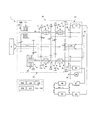
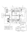
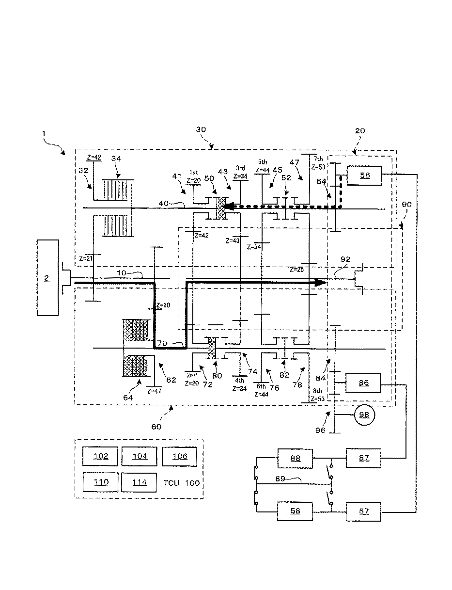
図1には、本発明の第1実施形態に係る変速機1の構成が示されている。この変速機1は、ディーゼルエンジン2の動力が入力される入力軸10と、入力軸10の回転が伝達される奇数段変速機構30と、同様に入力軸10の回転が伝達される偶数段変速機構60と、奇数段変速機構30及び偶数段変速機構60にモータの動力を入力するモータ動力機構20と、奇数段変速機構30及び偶数段変速機構60の動力が選択的に伝達される出力機構90と、これらの変速動作を制御する変速制御装置(TCU)100を備える。奇数段変速機構30は、第1速、第3速、第5速、第7速の変速を実行するものであり、偶数段変速機構60は、第2速、第4速、第6速、第8速の変速を実行するものである。従って、この変速機1は、合計8段の変速が可能となっている。変速機1では、奇数段変速機構30と偶数段変速機構60のそれぞれにクラッチを設けておくことで、例えば奇数段変速機構30において動力を伝達している際、偶数段変速機構60側において隣接段へのシフトアップ又はシフトダウンの準備を可能にする。また、偶数段変速機構60において動力を伝達している際、奇数段変速機構30側において隣接段へのシフトアップ又はシフトダウンの準備を可能にする。
FIG. 1 shows the configuration of a
奇数段変速機構30は、入力軸10の回転を伝達する奇数段伝達ギア列32と、奇数段伝達ギア列32の動力を奇数段伝達軸40に選択的に伝達する奇数段メインクラッチ34と、奇数段伝達軸40に設けられて出力機構90に回転を4段階で伝達する第1〜第7奇数段変速ギア列41、43、45、47と、第1〜第7奇数段変速ギア列41、43、45、47と奇数段伝達軸40を選択的に結合する奇数段メカニカルクラッチ50、52を備える。
The odd
奇数段伝達ギア列32は、入力歯数21、出力歯数42、回転比2.000となる歯車対によって構成されている。この奇数段伝達ギア列32は、入力軸10と奇数段メインクラッチ34の間に設けられており、入力軸10の回転を減速して奇数段メインクラッチ34に伝える。奇数段メインクラッチ34は、湿式多板クラッチであり、油圧を利用して、入力軸10の回転を奇数段伝達軸40に選択的に伝達可能となっている。
The odd-numbered
従って、奇数段変速機構30は、奇数段メインクラッチ34を利用して回転比2.000によって入力軸10の回転を奇数段伝達軸40に選択的に伝達する。
Accordingly, the odd
奇数段伝達軸40に設けられる第1速変速ギア列41は、入力歯数20、出力歯数42、回転比2.100となる歯車対によって構成されており、奇数段伝達軸40の回転を出力機構90の出力軸92に伝達する。第3速変速ギア列43は、入力歯数34、出力歯数43、回転比1.265となる歯車対によって構成されており、奇数段伝達軸40の回転を出力機構90の出力軸92に伝達する。第5速変速ギア列45は、入力歯数44、出力歯数43、回転比0.773となる歯車対によって構成されており、奇数段伝達軸40の回転を出力機構90の出力軸92に伝達する。第7速変速ギア列47は、入力歯数53、出力歯数25、回転比0.472となる歯車対によって構成されており、奇数段伝達軸40の回転を出力機構90の出力軸92に伝達する。
The first speed
奇数段メカニカルクラッチ50は、第1速変速ギア列41と第3速変速ギア列43の間に配置される。この奇数段メカニカルクラッチ50は、第1速変速ギア列41と奇数段伝達軸40が結合された「第1速結合状態」と、第3速変速ギア列43と奇数段伝達軸40が結合された「第3速結合状態」と、第1速及び第3速変速ギア列41、43が共に奇数段伝達軸40から解放された「非結合状態」を選択的に切り替えることが出来る。
The odd-numbered mechanical clutch 50 is disposed between the first speed
他方の奇数段メカニカルクラッチ52は、第5速変速ギア列45と第7速変速ギア列47の間に配置される。この奇数段メカニカルクラッチ52は、第5速変速ギア列45と奇数段伝達軸40が結合された「第5速結合状態」と、第7速変速ギア列47と奇数段伝達軸40が結合された「第7速結合状態」と、第5速及び第7速変速ギア列45、47が共に奇数段伝達軸40から解放された「非結合状態」を選択的に切り替えることが出来る。従って、この奇数段メカニカルクラッチ50、52を適宜切り替えることで、第1速、第3速、第5速、第7速、及び中立のいずれかを適宜選択できるようになっている。
The other odd-stage mechanical clutch 52 is arranged between the fifth speed
出力機構90は、出力軸92を備える。この出力軸92の動力は、特に図示しないプロペラシャフト、デファレンシャル・ギア等を介して車輪に伝達される。
The
偶数段変速機構60は、入力軸10の回転を伝達する偶数段伝達ギア列62と、偶数段伝達ギア列62の動力を偶数段伝達軸70に選択的に伝達する偶数段メインクラッチ64と、偶数段伝達軸70に設けられて出力機構90に回転を4段階で伝達する第2〜第8偶数段変速ギア列72、74、76、78と、第2〜第8偶数段変速ギア列72、74、76、78と偶数段伝達軸70を選択的に結合する偶数段メカニカルクラッチ80、82を備える。
The even
偶数段伝達ギア列62は、入力歯数30、出力歯数47、回転比1.567となる歯車対によって構成されている。
The even-numbered
この偶数段伝達ギア列62は、入力軸10と偶数段メインクラッチ64の間に設けられており、入力軸10の回転を減速して偶数段メインクラッチ64に伝える。偶数段メインクラッチ64は、湿式多板クラッチであり、入力軸10の回転を偶数段伝達軸70に選択的に伝達可能となっている。
The even-numbered
偶数段変速機構60は、定常時は、偶数段メインクラッチ64を利用して回転比1.567によって入力軸10の回転を偶数段伝達軸70に選択的に伝達する。
The even-
偶数段伝達軸70に設けられる第2速変速ギア列72は、入力歯数20、出力歯数42、回転比2.100となる歯車対によって構成されており、偶数段伝達軸70の回転を出力機構90の出力軸92に伝達する。なお、この歯車対における出力側歯車は、奇数段変速機構30の第1速変速ギア列41の歯車対と共用されている。また、第2速変速ギア列72と第1速変速ギア列41の回転比も略同じ(ここでは完全に同一)に設定されている。ここでは実際に、第2速変速ギア列72と第1速変速ギア列41において全く同じ歯車が用いられている。この結果、変速機1全体において、第1速の入出力回転比と第2速の入出力回転比の比率は、奇数段伝達ギア列32と偶数段伝達ギア列62の回転比の比率と一致する。
The second speed
第4速変速ギア列74は、入力歯数34、出力歯数43、回転比1.265となる歯車対によって構成されており、偶数段伝達軸70の回転を出力機構90の出力軸92に伝達する。なお、この歯車対における出力側歯車は、奇数段変速機構30の第3速変速ギア列43の歯車対と共用されている。また、第4速変速ギア列74と第3速変速ギア列43の回転比も略同じ(ここでは完全に同一)に設定されていることから、本実施形態では、第4速変速ギア列74と第3速変速ギア列43で全く同じ歯車が用いられている。この結果、変速機1全体において、第3速の入出力回転比と第4速の入出力回転比の段間比は、奇数段伝達ギア列32と偶数段伝達ギア列62の回転比の比率と一致する。
The fourth speed
第6速変速ギア列76は、入力歯数44、出力歯数34、回転比0.773となる歯車対によって構成されており、偶数段伝達軸70の回転を出力機構90の出力軸92に伝達する。なお、この歯車対における出力側歯車は、奇数段変速機構30の第5速変速ギア列45の歯車対と共用されている。また、第6速変速ギア列76と第5速変速ギア列45の回転比も略同じ(ここでは完全に同一)に設定されていることから、本実施形態では、第6速変速ギア列76と第5速変速ギア列45で全く同じ歯車が用いられている。この結果、変速機1全体において、第5速の入出力回転比と第6速の入出力回転比の段間比は、奇数段伝達ギア列32と偶数段伝達ギア列62の回転比の比率と一致する。
The sixth speed
第8速変速ギア列78は、入力歯数53、出力歯数25、回転比0.472となる歯車対によって構成されており、偶数段伝達軸70の回転を出力機構90の出力軸92に伝達する。なお、この歯車対における出力側歯車は、奇数段変速機構30の第7速変速ギア列47の歯車対と共用されている。また、第8速変速ギア列78と第7速変速ギア列47の回転比も略同じ(ここでは完全に同一)に設定されていることから、本実施形態では、第8速変速ギア列78と第7速変速ギア列47で全く同じ歯車が用いられている。この結果、変速機1全体において、第7速の入出力回転比と第8速の入出力回転比の段間比は、奇数段伝達ギア列32と偶数段伝達ギア列62の回転比の比率と一致する。
The eighth
偶数段メカニカルクラッチ80は、第2速変速ギア列72と第4速変速ギア列74の間に配置される。偶数段メカニカルクラッチ80は、第2速変速ギア列72と偶数段伝達軸70が結合された「第2速結合状態」と、第4速変速ギア列74と偶数段伝達軸70が結合された「第4速結合状態」と、第2速及び第4速変速ギア列72、74が共に偶数段伝達軸70から解放された「非結合状態」を選択的に切り替えることが出来る。
The even-numbered mechanical clutch 80 is disposed between the second speed
偶数段メカニカルクラッチ82は、第6速変速ギア列76と第8速変速ギア列78の間に配置される。偶数段メカニカルクラッチ82は、第6速変速ギア列76と偶数段伝達軸70が結合された「第6速結合状態」と、第8速変速ギア列78と偶数段伝達軸70が結合された「第8速結合状態」と、第6速及び第8速変速ギア列76、78が共に偶数段伝達軸70から解放された「非結合状態」を選択的に切り替えることが出来る。従って、この偶数段メカニカルクラッチ80、82を適宜切り替えることで、第2速、第4速、第6速、第8速、及び中立のいずれかを適宜選択できるようになっている。
The even-numbered mechanical clutch 82 is disposed between the sixth speed
モータ動力機構20は、奇数段伝達軸40の端部に設けられる奇数段モータ用ギア列54と、この奇数段モータ用ギア列54に接続される奇数段モータ56を備える。なお、奇数段モータ56には、奇数段インバータ57及び奇数段バッテリ58が接続されている。奇数段モータ56は、奇数段モータ用ギア列54を経由して奇数段伝達軸40を回転させる。これによって、第1〜第7奇数段変速ギア列41、43、45、47のいずれかとの奇数段伝達軸40の回転を同期させて、奇数段メカニカルクラッチ50、52を結合させる。即ち、目的の奇数段数へのシフトアップ・シフトダウンを実現する。なお、回生時には、奇数段伝達軸40の回転が奇数段モータ用ギア列54を経由して奇数段モータ56に伝達される。
The
更にモータ動力機構20は、偶数段伝達軸70の端部に設けられる偶数段モータ用ギア列84と、この偶数段モータ用ギア列84に接続される偶数段モータ86を備える。なお、偶数段モータ86には、偶数段インバータ87及び偶数段バッテリ88が接続されている。通常時は、偶数段バッテリ88と奇数段バッテリ58は直列接続されているが、一方のバッテリが故障した場合等を想定し、故障したバッテリをこの電源回路から切り離すための遮断路89も備えている。
Further, the
偶数段モータ86は、偶数段モータ用ギア列84を経由して偶数段伝達軸70を回転させる。これによって、第2〜第8偶数段変速ギア列72、74、76、78のいずれかと偶数段伝達軸70の回転を同期させて、偶数段メカニカルクラッチ80、82を結合させる。即ち、目的の偶数段数へのシフトアップ・シフトダウンを実現する。なお、回生時には、偶数段伝達軸70の回転が偶数段モータ用ギア列84を経由して偶数段モータ86に伝達される。
The
更にモータ動力機構20における偶数段モータ86は、外部伝達用ギア列96を経由して外部作業用アクチュエータ98に接続されている。ここでは、外部作業用アクチュエータ98として作業用油圧ポンプが用いられており、偶数段モータ86の動力によって駆動されるようになっている。この外部作業用アクチュエータ98は、例えば荷台を傾斜させたり、クレーンを動作させたりする場合に用いられる。偶数段モータ86で外部作業用アクチュエータ98を駆動することで、エンジンを停止させた状態で外部作業が可能となるので、夜間等において静かに作業することが可能となる。また、荷台やクレーンの荷重を降ろす場合、油圧モータで偶数段モータ86を駆動することで、位置エネルギーを回生することも可能となる。
Further, the even-numbered
以上のように構成された変速機1の第1速から第8速の回転比は次の表の通りとなる。
このことからも分かるように、本変速機1では、隣接する速度段の段間比が、1.277〜1.301(約1.289程度)にほぼ一定に設定されている。また、この段間比(約1.289)は、奇数段伝達ギア列32の回転比(2.000)と偶数段伝達ギア列62の回転比(1.567)の比率(1.276=2.000/1.567)と略一致する。
As can be seen from this, in the
次に、変速制御装置100を説明することによって、この変速機1変速動作について説明する。なお、ディーゼルエンジン2駆動の場合は、入力軸10を1000min−1で回転させている状態を想定する。Next, the
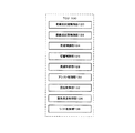
変速制御装置100は、特に図示しない各種センサやCPU、メモリ、電源装置等の他、各クラッチの状態を検出するクラッチセンサ102、第1〜第7奇数段変速ギア列41、43、45、47及び第2〜第8偶数段変速ギア列72、74、76、78の回転数を、直接又は間接的に検出可能な出力側回転センサ104、入力軸10の回転数(エンジン2の回転数)を直接又は間接的に検出可能な入力側回転センサ106等の各種センサ、変速機1の各クラッチを動作させるクラッチアクチュエータ110、モータを制御するモータコントローラ114等を含んで構成されており、メモリに格納されている所定のプログラムをCPUで実行することで変速機1を制御する。この変速制御装置100は、図2に示されるように、その機能構成として、奇数段同期制御部120、偶数段同期制御部122、発進制御部124、切替制御部126、減速制御部128、アシスト制御部130、回生制御部132、緊急発進制御部134、シフト制御部136を備える。各機能構成については、図3以降を参照しながら説明する。
The speed
<発進制御部による発進動作> <Starting operation by start control unit>
図3に示されるように、発進制御部124は、変速機1が停止した状態で、奇数段メカニカルクラッチ50を結合して「第1速結合状態」とすると同時に、偶数段メカニカルクラッチ80を結合して「第2速結合状態」とする。その後、奇数段モータ56及び偶数段モータ86を同時に回転させる。この結果、奇数段モータ56及び偶数段モータ86の双方の動力が出力軸92に伝達され、2つのモータによる高トルク駆動で発進することが出来る。従って、エンジン2による発進が不要となり、エンジン2側にトルクコンバータを設けたり、奇数段メインクラッチ34を半クラッチ状態で滑らせながら次第に結合させて発進するような制御も不要となり、素早い発進が可能となる。なお、後退(バック)する場合は、これらのモータを逆回転すれば良いので、逆転クラッチや逆転ギヤ等の機械的な後退機構を用意する必要が無く、変速機の構造の簡素化が図られる。
As shown in FIG. 3, the start control unit 124 connects the odd-numbered mechanical clutch 50 to the “first-speed connected state” while the
<切替制御部によるエンジンへの切替動作> <Switching operation to the engine by the switching control unit>
奇数段伝達軸40は約500min−1で回転する状態(入力軸10が1000min−1で回転することが出来る程度の速度)に達した際、切替制御部126は、図4に示されるように、エンジン2を起動させる。奇数段メインクラッチ34を半クラッチ状態にして出力側からエンジン2を回すことによって、このエンジン2を起動できるので、エンジン2のスタータの操作は不要となる。エンジン起動後に、奇数段メインクラッチ34を半クラッチ状態で滑らせながら次第に結合していく。この結果、エンジン2の動力が、入力軸10及び奇数段伝達ギア列32を介して奇数段伝達軸40に伝達され、エンジン駆動による第1速運転に切り替わる。これにより奇数段伝達軸40が約500min−1で回転する。奇数段伝達軸40の回転は、第1速変速ギア列41を介して出力軸92に伝達され、この結果、出力軸92は238.1min−1で回転する。同時に、奇数段モータ56及び偶数段モータ86の駆動を停止し、偶数段メカニカルクラッチ80は開放して「非結合状態」とする。When the odd
<偶数段同期制御部による第1速運転中の第2速準備> <Preparation of the second speed during the first speed operation by the even-numbered stage synchronous control unit>
第1速で走行している状態において、偶数段変速機構60の第2速変速ギア列72の入力歯車(偶数段伝達軸70側の歯車)は第1速変速ギア列41と同様に500min−1で回転している。偶数段同期制御部122は、図5に示されるように、偶数段モータ86を駆動させて、偶数段伝達軸70を略500min−1となるように制御する。この結果、偶数段伝達軸70と第2速変速ギア列72の回転が同期するので、偶数段メカニカルクラッチ80を結合して「第2速結合状態」とすることができる。これにより第2速へのシフトアップの準備が完了し、偶数段モータ86の駆動はOFFにする。In the state of traveling at the first speed, the input gear (the gear on the even-numbered
<シフト制御部による第1速から第2速へのシフトアップ> <Upshift from 1st speed to 2nd speed by shift control unit>
第2速にシフトアップする際、シフト制御部136は、図6に示されるように、偶数段メインクラッチ64を次第に結合させていく。この動作と同時に、奇数段メインクラッチ34を「非結合状態」にして、奇数段伝達軸40の回転が出力軸92に伝達されないようにする。これによりエンジンの回転が1000min−1まで上昇すると共に、偶数段伝達軸70が、500min−1から638min−1まで上昇し、出力軸92の回転が304min−1まで上昇する。これにより、第2速へのシフトアップが完了する。第2速運転中に次のシフトの準備として、奇数段メカニカルクラッチ50を「非結合状態」にしておく。When shifting up to the second speed, the shift control unit 136 gradually couples the even-numbered main clutch 64 as shown in FIG. Simultaneously with this operation, the odd-numbered main clutch 34 is set to the “uncoupled state” so that the rotation of the odd-numbered
<奇数段同期制御部における第2速運転中の第3速準備> <Preparation of the third speed during the second speed operation in the odd-numbered stage synchronous control section>
第2速で走行している状態において、奇数段変速機構30の第3速変速ギア列43の入力歯車(奇数段伝達軸40側の歯車)は、その回転比により384min−1で回転している。奇数段同期制御部120は、図7に示されるように、奇数段モータ56を駆動させて、奇数段伝達軸40を略384min−1となるように制御する。この結果、奇数段伝達軸40と第3速変速ギア列43の回転が同期するので、奇数段メカニカルクラッチ50を結合して「第3速結合状態」とすることができる。これにより第3速へのシフトアップの準備が完了し、奇数段モータ56の駆動はOFFにする。In the state where the vehicle travels at the second speed, the input gear (the gear on the odd-numbered
<シフト制御部による第2速から第3速へのシフトアップ> <Upshift from 2nd speed to 3rd speed by shift control unit>
第3速にシフトアップする際、シフト制御部136は、図8に示されるように、奇数段メインクラッチ34を次第に結合させていく。この動作と同時に、偶数段メインクラッチ64を「非結合状態」にして、偶数段伝達軸70の回転が出力軸92に伝達されないようにする。これによりエンジンの回転が1000min−1まで上昇すると共に、奇数段伝達軸40が、384min−1から500min−1まで上昇し、出力軸92の回転が395min−1まで上昇する。これにより、第3速へのシフトアップが完了する。第3速運転中に次のシフトの準備として、偶数段メカニカルクラッチ80を「非結合状態」にしておく。第4速以降のシフトアップも、これらと同様に実行されるので説明を省略する。When shifting up to the third speed, the shift control unit 136 gradually couples the odd-numbered main clutch 34 as shown in FIG. Simultaneously with this operation, the even-numbered main clutch 64 is set to the “uncoupled state” so that the rotation of the even-numbered
<偶数段同期制御部による第3速運転中の第2速準備> <Preparation of the second speed during the third speed operation by the even-numbered stage synchronous control section>
第3速運転から第2速運転にシフトダウンする場合は、その準備として、第2速変速ギア列72を偶数段伝達軸70に結合させる。具体的に、第3速運転中は、出力軸92の回転が395min−1であることから、偶数段変速機構60の第2速変速ギア列72の偶数段伝達軸70側の歯車は、830min−1で回転している。図9に示されるように、偶数段同期制御部122は、偶数段モータ86を駆動させて、偶数段伝達軸70の回転を830min−1まで増大させる。この結果、偶数段伝達軸70と第2速変速ギア列72の回転が略同期するので、偶数段メカニカルクラッチ80を結合して「第2速結合状態」とすることができる。これにより第2速へのシフトダウンの準備が完了し、偶数段モータ86の駆動はOFFにする。When shifting down from the third speed operation to the second speed operation, the second speed
<シフト制御部による第3速から第2速へのシフトダウン> <Shifting down from 3rd speed to 2nd speed by shift control unit>
第2速にシフトダウンする際、シフト制御部136は、図10に示されるように、偶数段メインクラッチ64を次第に結合させる。この動作と同時に、奇数段メインクラッチ34を「非結合状態」にして、奇数段伝達軸40の回転が出力軸92に伝達されないようにする。これによりエンジンの回転が1000min−1まで下降すると共に、偶数段伝達軸70が830min−1から638min−1まで下降し、出力軸92の回転が304min−1まで下降する。これにより、第2速へのシフトダウンが完了する。第2速運転中に次のシフトの準備として、奇数段メカニカルクラッチ50を「非結合状態」にしておく。When shifting down to the second speed, the shift control unit 136 gradually couples the even-numbered main clutch 64 as shown in FIG. Simultaneously with this operation, the odd-numbered main clutch 34 is set to the “uncoupled state” so that the rotation of the odd-numbered
<奇数段同期制御部による第2速運転中の第1速準備> <Preparation of the first speed during the second speed operation by the odd-numbered stage synchronous control unit>
第2速運転から第1速運転にシフトダウンする場合は、その準備として、第1速変速ギア列41を奇数段伝達軸40に結合させる。具体的に、第2速運転中は、出力軸92の回転が304min−1であることから、奇数段変速機構30の第1速変速ギア列41の奇数段伝達軸40側の歯車は、638min−1で回転している。図11に示されるように、奇数段同期制御部120は、奇数段モータ56を駆動させて、奇数段伝達軸40の回転を638min−1まで増大させる。この結果、奇数段伝達軸40と第1速変速ギア列41の回転が略同期するので、奇数段メカニカルクラッチ50を結合して「第1速結合状態」とすることができる。これにより第1速へのシフトダウンの準備が完了し、奇数段モータ56の駆動はOFFにする。When shifting down from the second speed operation to the first speed operation, the first speed
<シフト制御部による第2速から第1速へのシフトダウン> <Shifting down from the second speed to the first speed by the shift control unit>
第1速にシフトダウンするには、図12に示されるように、シフト制御部136は、奇数段メインクラッチ34を次第に結合させる。この動作と同時に、偶数段メインクラッチ64を「非結合状態」にして、偶数段伝達軸70の回転が出力軸92に伝達されないようにする。これによりエンジンの回転が1000min−1まで下降すると共に、奇数段伝達軸40が638min−1から500min−1まで下降し、出力軸92の回転が238min−1まで下降する。これにより、第1速へのシフトダウンが完了する。第1速運転中に次のシフトの準備として、偶数段メカニカルクラッチ80を「非結合状態」にしておく。To shift down to the first speed, the shift control unit 136 gradually connects the odd-numbered main clutch 34 as shown in FIG. Simultaneously with this operation, the even-numbered main clutch 64 is set to the “uncoupled state” so that the rotation of the even-numbered
<減速制御部における回生ブレーキ> <Regenerative braking in the deceleration control unit>
例えばエンジン2による第2速運転中に減速する際、減速制御部128は、図13に示されるように、偶数段メカニカルクラッチ80の結合に加えて、奇数段メカニカルクラッチ50、52を用いて奇数段のいずれかを結合させる。この結合段数は、第1速、第3速、第5速、第7速のいすれでも良いが、回生ブレーキ効率を高めるためにも、好ましくは低い段数(例えば第1速)とする。なお、奇数段メカニカルクラッチ50、52を結合させるには、奇数段同期制御部120によって、一時的に奇数段モータ56を駆動して同期をとる。なおここでは「第1速結合状態」とする場合を示している。このように、奇数段メカニカルクラッチ50と偶数段メカニカルクラッチ80の双方を結合させた状態で、出力軸92の回転を奇数段モータ54及び偶数段モータ86の双方に伝達させて、これらモータで回生ブレーキをかける。これにより、バッテリ58、88が充電されることになる。なお、ここでは第1速結合状態とすることで、奇数段モータ56の回転数を増大させて、回生効率を高めるようにしているが、走行状態によって、最適な段数を適宜選択して結合すれば良い。
For example, when decelerating during the second speed operation by the
<アシスト制御部による加速動作> <Acceleration operation by assist control unit>
例えばエンジン2による第2速運転中に急加速する際、アシスト制御部130は、図14に示されるように、偶数段モータ86を駆動して動力アシストを行う。これにより、エンジン2のトルクが補われるので、急加速が可能となる。なお、ここでは特に図示しないが、偶数段メカニカルクラッチ80の結合に加えて、奇数段メカニカルクラッチ50、52を用いて奇数段のいずれかを結合させ、奇数段モータ56による動力アシストを加えることも可能である。
For example, when rapidly accelerating during the second speed operation by the
<回生制御による余分エネルギーの回収> <Recovery of excess energy by regenerative control>
例えばエンジン2による第8速運転(偶数段変速機構60による運転)が安定して続くことで、エンジン2のトルクが余っている際、回生制御部132は、図15に示されるように、奇数段変速機構30において、奇数段メカニカルクラッチ50、52を用いて、奇数段のいずれかを「結合状態」とし、エンジン2の余分な動力を奇数段モータ56に伝達させることで回生させて、バッテリ58、88を充電する。このようにすることで、エンジン2の余分なエネルギーを電気的に回収することが可能となる。また、回生目的の奇数段メカニカルクラッチの結合段数は、第1速、第3速、第5速、第7速のいすれでも良いが、回生ブレーキ効率を高めるためにも、好ましくは低い段数(例えば第1速)とする。なお、結合させるには、奇数段同期制御部120によって、一時的に奇数段モータ56を駆動して同期を図るようにする。ここでは「第1速結合状態」とすることで、奇数段モータ56の回転数を増大させて、回生効率を高めるようにしているが、走行状態によって、最適な段数を適宜選択して結合すれば良い。なお、特に図示しないが、例えば第7速運転のように奇数段変速機構30側で安定走行している最中は、偶数段変速機構60側で回生すれば良い。
For example, when the
<緊急発進制御部による緊急発進> <Emergency start by emergency start control unit>
例えば、発進時においてバッテリ58、88の双方の残量がゼロとなる場合、緊急発進制御部134は、図16に示されるように、エンジン2を起動させ、更に奇数段メインクラッチ34を開放すると共に偶数段メインクラッチ64を結合させる。この結果、エンジン2の動力によって偶数段伝達軸70を経由して偶数段モータ86が回転して、バッテリ58、88が充電される。このように充電を行う一方、奇数段メカニカルクラッチ50を「第1速結合状態」としてから、この充電中のバッテリ58、88を利用して、奇数段モータ56を回転させて緊急発進を行う。双方のモータを利用する通常の発進動作よりもトルクは不足するが、バッテリ58、88が切れた場合の緊急用途として十分な役割を発揮できる。なお、ここでは奇数段変速機構30の奇数段モータ56で発進し、偶数段変速機構60で充電する場合を示したが、勿論、反対も可能である。
For example, when both the
仮に、バッテリ58、88の双方が故障した場合は、更なる緊急用として、図17に示されるように、奇数段メカニカルクラッチ50を結合して「第1速結合状態」とすると同時に、偶数段メカニカルクラッチ80を結合して「第2速結合状態」としておき、奇数段メインクラッチ34と偶数段メインクラッチ64の双方を半クラッチにしてスリップさせながら、エンジン2の動力を出力軸92に伝達させて発進すれば良い。ダンプトラック等を発進させるには、相応のトルク伝達が必要となるが、奇数段メインクラッチ34と偶数段メインクラッチ64の双方を同時に利用することで、各メインクラッチ34、64の負荷を半減することができるので、これらのメインクラッチ34、64をコンパクトにすることができる。
If both of the
以上、本実施形態の変速機1では、ツインクラッチ式の変速機構において、モータ動力機構20が、奇数段側に奇数段モータ56、偶数段側に偶数段モータ86を備えることで、これらのモータ56、86でメカニカルクラッチの同期制御を実現している。この結果、同期専用のシンクロメッシュや湿式多板クラッチが不要となる。また、モータ56、86により素早い同期が可能となるので、素早いシフトアップ、シフトダウンが実現される。また、2つのモータ56、86を利用することで、各モータを小型化することが可能となる。モータによる略完全な同期が実現されることから、メカニカルクラッチによって伝達軸40、70と変速ギア列を結合する事が可能となる。メカニカルクラッチは、湿式多板クラッチと較べて、非結合時の空転ロスが各段に少ないため、運転時の伝達効率が大幅に高められる。
As described above, in the
更にこの変速機1では、モータ56、86を有効活用して、高トルクの発進動作(後退動作)が可能となっている。従って、エンジン2側にトルクコンバータが不要になるので、低速運転時のトルクコンバータによる伝達ロスを回避して、伝達効率を高めることが可能となる。また、トルクコンバータの場合、高速運転時にロックアップさせても、コンバータ内部の油が羽に衝突して内部ロスが生じるが、本変速機1はそもそもトルクコンバータが不要となるので、高速運転中の伝達効率を高めることが可能となる。また、変速機1内の設けられる湿式多板クラッチが2カ所(メインクラッチ34、64)で済む。更に、これら2つの湿式多板クラッチにおける、一方の「非結合状態」となっているクラッチでも、入出力の回転差が小さいので、空転ロスを小さくすることが可能となる。なお、湿式多板クラッチの発熱も抑制されるので、油を冷却するためのラジエターを不要にすることもできる。これは、各湿式多板クラッチの耐久性の向上にもつながる。
Further, in the
また、トルクコンバータが不要になることに伴い、変速機1の全長を大幅に短縮することができる。更に、高いトルクが要求される発進時に、モータを用いることが可能であり、エンジン2の動力を奇数段及び偶数段メインクラッチ34、64を介して伝達する必要が無くなるので、奇数段及び偶数段メインクラッチ34、64の容量を小さくすることが出来、これによっても変速機1をコンパクトに構成できる。
Further, as the torque converter becomes unnecessary, the overall length of the
また、変速機1では、仮にバッテリ58、88の全てが空になったとしても、エンジン2の動力を利用して、奇数段又は偶数段変速機構30、60の一方を利用してバッテリ58、88の充電を行い、他方を利用してモータによる発進が可能となるので、このツインクラッチ式の特徴を合理的に活用して確実な発進動作が可能となっている。
Further, in the
更にこの変速機1では、モータ56、86を用いて、エンジン2の動力をアシストすることができるので、加速性能を向上させることが出来る。例えば、登坂時等においてもモータ56、86でアシストすることで、エンジン2のトルク不足を補うことが出来る。この結果、エンジン2の排気量を小さくすることが出来る。
Furthermore, in this
また、この変速機1では、2つのモータ56、86を用いて回生ブレーキをかけることで、エネルギーを効率よく回収することが出来、また、第7速や第8速による安定走行時においても、エンジン2の余分なエネルギーを、2つのモータ56、86を用いて効率よく回生することができる。その結果、燃費を向上させることができる。
Moreover, in this
また更に、この変速機1では、バッテリ58、88を2つ備えるので、一方のバッテリが故障しても、他方のバッテリで走行を続けることが可能となる。仮に双方のバッテリ58、88が故障しても、各メインクラッチ34、64を半クラッチにしながらエンジン2による発進も可能となるので、非常時に柔軟に対応することが出来る。
Furthermore, since the
更にまた、この変速機1では、これらのモータ56、86を利用して外部作業用アクチュエータ98を駆動できるので、停車中の作業が電気駆動となり、作業時の低騒音化が図られる。例えば、夜間において、油圧モータを用いて荷台やクレーンを上昇させる場合においても、駆動源がモータとなるので、静かに作業を進めることが出来る。なお、この荷台やクレーンを下降させる際には、その位置エネルギーを油圧モータを介してモータ56、88に伝達して回生することも可能である。
Furthermore, in this
更に本変速機1では、例えば、第1速変速ギア列41と第2速変速ギア列72のように、隣接する変速ギア列間のギア比を略一致させている。この結果、第1速変速ギア列41と第2速変速ギア列72の間で同じ歯車を用いたり、出力軸92の歯車を共用したりすることが可能になる。歯車の共用化によって、本変速機1は8段構成であるにもかかわらず、軸方向サイズは実質的に4段レベルとなり、変速機1を大幅に小型化することも可能となっている。もちろん、歯車を共用しないで、速度比を優先させた構成も可能である。
Further, in the
更に、本実施形態では、奇数段伝達軸40に対する偶数段伝達軸70の回転比、即ち、奇数段伝達ギア列32の回転比と偶数段伝達ギア列62の回転比の割合(比率)が、この段間比1.289と略一致させている。この結果、既述のとおり、例えば、第1速変速ギア列41と第2速変速ギア列72のギア比のように、隣接する変速段の変速ギア列のギア比を略一致させることができる。これは、奇数段伝達ギア列32と偶数段伝達ギア列62の回転比(段間比に等しい)によって、目的の段間比を確保できるからである。なお、第2速変速ギア列72と第3速変速ギア列43のギア比の比率は、段間比(1.289)の略二乗(1.66)に設定される。これらの設定により変速時、切替時における制御の簡素化も可能となっている。
Further, in the present embodiment, the rotation ratio of the even-numbered
例えば本実施形態では、第1奇数段変速ギア列41と第2偶数段変速ギア列72の間のアップ/ダウンシフトは、奇数段伝達軸40と偶数段伝達軸70を等速回転させることで同期させることができる。このことは、第3奇数段変速ギア列43と第4偶数段変速ギア列74の間や、第5奇数段変速ギア列45と第6偶数段変速ギア列76の間、第7奇数段変速ギア列47と第8偶数段変速ギア列78の間においても同様である。また、第2偶数段変速ギア列72と第3奇数段変速ギア列43の間のアップ/ダウンシフトは、奇数段伝達軸40と偶数段伝達軸70を、段間比の略二乗の比で回転させることで同期させることができる。このことは、第4偶数段変速ギア列74と第5奇数段変速ギア列45の間や、第6偶数段変速ギア列76と第7奇数段変速ギア列47の間においても同様である。
For example, in the present embodiment, the up / down shift between the first odd speed
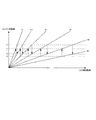
従って、図18に示されるように、アップシフト前後のエンジンの回転速度a1、a2や、ダウンシフト前後のエンジンの回転速度b1、b2を速度段に拘わらず略一定に設定すれば、アップシフト時の奇数段伝達軸40と偶数段伝達軸70の回転速度や、ダウンシフト時の奇数段伝達軸40と偶数段伝達軸70の回転速度を、速度段に拘わらず略一定にすることができる。結果、速度段切換時の同期制御が簡素化されるので、シフト時間を短縮することができる。例えば、モータ動力機構20における奇数段モータ56や偶数段モータ86を直流モータとし、アップシフト時とダウンシフト時の2種類の電圧値を制御するだけで、速度段切換時に同期を図ることも可能になる。この結果、モータ制御用のインバータを不要にしてもよい。
Therefore, as shown in FIG. 18, if the engine rotational speeds a1 and a2 before and after the upshift and the engine rotational speeds b1 and b2 before and after the downshift are set to be substantially constant regardless of the speed stage, The rotational speeds of the odd-numbered
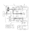
〔第1実施形態の変形例1〕
[
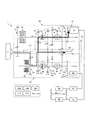
図19には、第1実施形態に係る変速機1の変形例が示されている。この変速機1では、モータ動力機構20において、奇数段モータ56や偶数段モータ86の容量が互いに異なるように設定されている。特に、奇数段モータ56の容量が偶数段モータ86と比較して大きく設定されている。偶数段モータ86は、速度段切換時の同期動作のみに用いられるが、奇数段モータ56は、速度段切換時の同期動作に加えて、発進動作やエンジンアシスト動作、回生ブレーキ動作、エンジン回生動作を行うようになっている。
FIG. 19 shows a modification of the
発進時は、図19に示されるように、変速機1が停止した状態で、奇数段メカニカルクラッチ50を結合して「第1速結合状態」とし、奇数段モータ56を回転させて発進を行う。奇数段モータ56の容量は、単体で十分な発進トルクが得られるように設定しているので、高トルク駆動で発進することが出来る。
At the time of start, as shown in FIG. 19, with the
更に、回生ブレーキ動作やエンジン回生動作を行う場合は、図20に示されるように、奇数段のいずれかを「結合状態」とし、エンジン2の余分な動力や慣性力を、容量の大きい奇数段モータ56に伝達させることで回生させて充電する。このように、大容量の奇数段モータ56を積極的に回生動作に利用することで、回生効率を高めることが可能となる。
Furthermore, when performing regenerative braking operation or engine regenerative operation, as shown in FIG. 20, any one of the odd-numbered stages is set to the “coupled state”, and the extra power or inertial force of the
また、エンジン2による第2速運転中に急加速する際、図21に示されるように、奇数段メカニカルクラッチ50を結合して第1速を同時に結合させた状態とし、奇数段モータ56を駆動して動力アシストを行う。これにより、容量の大きい奇数段モータ56によって、偶数段運転時のエンジン2のトルクが補われるので、急加速が可能となる。勿論、奇数段運転時のエンジン2のトルクも、奇数段モータ56を駆動するだけで動力アシストを行うことができる。
Further, when sudden acceleration is performed during the second speed operation by the
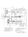
〔第1実施形態の変形例2〕
[
図22には、第1実施形態に係る変速機1の変形例2が示されている。この変速機1では、モータ動力機構20において、奇数段モータ56の容量が偶数段モータ86より大きくなるように設定される。更に、モータ動力機構20は、奇数段伝達軸40に設けられる奇数段モータ用ギア列54Aと、奇数段モータ56と奇数段伝達軸40を選択的に結合する奇数段モータクラッチ54Bを備えている。奇数段モータ56は、エンジン2側に併設されており、奇数段モータクラッチ54Bは、奇数段メインクラッチ34に隣接配置されている。
FIG. 22 shows a second modification of the
容量の大きい奇数段モータ56は、不使用中の空転ロスが大きい。従って、通常は、奇数段モータクラッチ54Bを開放しておくことで、奇数段モータ56の空転ロスを無くす。また、奇数段モータ56を用いて速度段切換時の同期動作や回生動作を行う場合は、奇数段モータクラッチ54Bを結合する。このようにすることで、動力の伝達効率を高めることができる。また、この変速機1では、容量の大きい奇数段モータ56をエンジン2側に併設しているので、変速機1の軸方向寸法をコンパクトにすることが可能となる。
The odd-numbered
なお、奇数段モータクラッチ54Bの態様は特に限定されず、湿式多板クラッチやメカニカルクラッチなどを採用することができる。 The aspect of the odd-numbered motor clutch 54B is not particularly limited, and a wet multi-plate clutch, a mechanical clutch, or the like can be employed.
〔第2実施形態〕 [Second Embodiment]
図23には、第2実施形態に係る変速機1が示されている。なお、モータ動力機構20を除いて、第1実施形態の変速機1と同一構造であるため、ここでは主としてモータ動力機構20について詳細に説明する。
FIG. 23 shows the
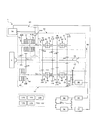
モータ動力機構20は、共通同期モータ22と、奇数段伝達軸40に設けられる奇数段モータ用ギア列54Aと、この共通同期モータ22と奇数段伝達軸40を選択的に結合する奇数段モータクラッチ54Bと、偶数段伝達軸70に設けられる偶数段モータ用ギア列84Aと、共通同期モータ22と偶数段伝達軸70を選択的に結合する偶数段モータクラッチ84Bを備える。このようにすることで、第1実施形態と異なり、一つの共通同期モータ22を利用して、奇数段伝達軸40と偶数段伝達軸70をそれぞれ回転させることができる。
The
例えば図24に示されるように、発進時には、変速機1が停止した状態で、奇数段メカニカルクラッチ50を結合して「第1速結合状態」とすると同時に、奇数段モータクラッチ54Bを結合して、共通同期モータ22を回転させる。この結果、共通同期モータ22の動力が出力軸92に伝達されて高トルク駆動で発進することが出来る。
For example, as shown in FIG. 24, when starting, with the
また、図25に示されるように、第1速でエンジン走行している状態で第2速にシフトアップする際は、奇数段モータクラッチ54Bを開放すると共に偶数段モータクラッチ84Bを結合して、共通同期モータ22によって偶数段伝達軸70を同期制御する。この結果、偶数段メカニカルクラッチ80を結合して「第2速結合状態」とすることができる。これにより第2速へのシフトアップの準備を完了せることができる。
Also, as shown in FIG. 25, when shifting up to the second speed while the engine is running at the first speed, the odd-numbered motor clutch 54B is released and the even-numbered motor clutch 84B is coupled, The even-numbered
また、回生ブレーキをかける際や、エンジン2の動力を回生する際は、奇数段モータクラッチ54B又は偶数段モータクラッチ84Bを結合して、エンジン2の余分な動力や慣性力を共通同期モータ22に伝達して回生する。
Further, when the regenerative braking is applied or when the power of the
また例えば、エンジン2による第2速運転中に急加速する際、図26に示されるように、偶数段モータクラッチ84Bを結合して、共通同期モータ22を駆動して動力アシストを行う。これにより、容量の大きい共通同期モータ22によってエンジン2のトルクが補われるので、急加速が可能となる。
Further, for example, when sudden acceleration is performed during the second speed operation by the
なお、共通同期モータ22を停止させる際は、奇数段モータクラッチ54Bと偶数段モータクラッチ84Bの双方を開放することで、空転ロスを無くすことができる。
When the common
〔第3実施形態〕 [Third Embodiment]
図27には、第3実施形態に係る変速機1が示されている。なお、モータ動力機構20と、後述する同期用変速機構200を除いて、第1実施形態の変速機1と同一構造であるため、ここでは主としてモータ動力機構20とメカニカル同期機構200について詳細に説明する。
FIG. 27 shows the
モータ動力機構20は、奇数段モータ56と、奇数段伝達軸40に設けられる奇数段モータ用ギア列54Aと、奇数段モータ56と奇数段伝達軸40を選択的に結合する奇数段モータクラッチ54Bを備えている。この奇数段モータ56は、同期目的ではなく、エンジン2の動力アシストと回生目的で利用される。
The
同期用変速機構200は、奇数段変速機構30と偶数段変速機構60の変速時の同期を行う。この同期用変速機構200は、第1同期ギア列210と第2同期ギア列220を備える。第1同期ギア列210は、奇数段伝達軸40と偶数段伝達軸70の回転が第1回転比となるように、この奇数段伝達軸40と偶数段伝達軸70を選択的に結合する。具体的に第1同期ギア列210は、奇数段伝達軸40に設けられる第1同期クラッチ212と、第1同期クラッチ212に連結される第1奇数段同期ギア214と、出力軸92に対して自由回転自在に設置され、且つ第1奇数段同期ギア214と噛み合う第1中間同期ギア216と、偶数段伝達軸70に固定されて第1中間同期ギア216と噛み合う第1偶数段同期ギア218を備える。本実施形態では、第1奇数段同期ギア214と第1偶数段同期ギア218の歯数が同じとなるように設定されているので、第1回転比は「ほぼ1」となる。従って第1同期クラッチ212を接続すると、この奇数段伝達軸40と偶数段伝達軸70が同じ速度で回転する。
The
第2同期ギア列220は、奇数段伝達軸40と偶数段伝達軸70の回転が第2回転比となるように、この奇数段伝達軸40と偶数段伝達軸70を選択的に結合する。具体的に第2同期ギア列220は、偶数段伝達軸70に設けられる第2同期クラッチ222と、第2同期クラッチ222に連結される第2偶数段同期ギア224と、出力軸92に対して自由回転自在に設置され、且つ第2偶数段同期ギア224と噛み合う第2大径側中間同期ギア226Aと、第2大径側中間同期ギア226Aに同軸状に連結され、且つ第2大径側中間同期ギア226Aよりも歯数の少ない第2小径側中間同期ギア226Bと、奇数段伝達軸40に固定され、且つ第2小径側中間同期ギア226Bと噛み合う第2奇数段同期ギア228を備える。本実施形態では、第2回転比が第1回転比と異なるように設定されており、詳細に第2回転比は、第1速から第8速の「ほぼ段間比の二乗」に一致するようになっている。同期用変速機構は遊転(又は停止)している奇数段伝達軸(又は偶数段伝達軸)を同期回転数まで加速(又は減速)するが、慣性のみの加速(減速)となる為、容量の小さいギア、クラッチで構成され、コンパクトに配設することが可能である。なお、第1同期クラッチ212と第2同期クラッチ222は、回転差のある状態で結合するため、湿式多板クラッチが採用されている。
The second
例えば、第1速でエンジン走行している状態において、第2速変速ギア列72の入力歯車と偶数段伝達軸70で同期を取る際は、図27に示されるように、同期用変速機構200の第1同期ギア列210を結合させて、奇数段伝達軸40と偶数段伝達軸70の回転を強制的に等速(比率1)にする。この結果、偶数段伝達軸70と第2速変速ギア列72の回転が同期するので、偶数段メカニカルクラッチ80を結合して「第2速結合状態」とすることができる。これにより第2速へのシフトアップの準備が完了させることができる。
For example, in the state where the engine is running at the first speed, when synchronizing with the input gear of the second-speed
また例えば、第2速でエンジン走行している状態において、第3速変速ギア列43の入力歯車と奇数段伝達軸40の同期を取るためには、図28に示されるように、同期用変速機構200の第2同期ギア列220を結合させ、奇数段伝達軸40と偶数段伝達軸70の回転を、上記段間比の二乗(約1.66)の比で強制的に回転させる。この結果、奇数段伝達軸40と第3速変速ギア列43の回転が同期するので、奇数段メカニカルクラッチ50を結合して「第3速結合状態」とすることができる。これにより第3速へのシフトアップの準備が完了させることができる。
Also, for example, in order to synchronize the input gear of the third speed
この第3実施形態では、同期用変速機構200を用いることによって、速度段の変換を機械的に行うようにしている。結果、奇数段モータ56は、エンジン2のアシストと動力回生に特化することができる。特に、偶数段によるエンジン走行時であっても、同期用変速機構200を結合すれば、奇数段モータ56によって動力アシストや動力回生を行うことが可能となる。
In the third embodiment, by using the
以上、本実施形態の変速機1では、大型ダンプトラック用途の場合を例示したが、その用途は特に限定されず、バス、トラック、自動車、建設機械、気動車等、様々な用途に用いることが出来る。
As mentioned above, in the
尚、本発明の変速機は、上記した実施の形態に限定されるものではなく、本発明の要旨を逸脱しない範囲内において種々変更を加え得ることは勿論である。例えば、特開2003−269592号の第1入力軸及び第2入力軸の軸端に、それぞれモータを設けた形態も含まれる。 It should be noted that the transmission of the present invention is not limited to the above-described embodiment, and it is needless to say that various changes can be made without departing from the scope of the present invention. For example, the form which provided the motor in the shaft end of 1st input shaft and 2nd input shaft of Unexamined-Japanese-Patent No. 2003-269592 is also included, respectively.
本発明のツインクラッチ式ハイブリッド変速機は、動力伝達の様々な用途で利用することが可能である。 The twin clutch hybrid transmission of the present invention can be used in various applications for power transmission.
Claims (24)
前記入力軸の回転が伝達される奇数段変速機構と、
前記入力軸の回転が伝達される偶数段変速機構と、
前記奇数段変速機構及び前記偶数段変速機構の少なくとも一方にモータの動力を入力するモータ動力機構と、
前記奇数段変速機構及び前記偶数段変速機構の動力が伝達される出力機構と、を備え、
前記奇数段変速機構は、
前記入力軸の回転を伝達する奇数段伝達ギア列と、
前記奇数段伝達ギア列の動力を奇数段伝達軸に選択的に伝達する奇数段メインクラッチと、
前記奇数段伝達軸に設けられて前記出力機構に回転を伝達する奇数段変速ギア列と、
前記奇数段変速ギア列と前記奇数段伝達軸を選択的に結合する奇数段メカニカルクラッチと、を備え、
前記偶数段変速機構は、
前記入力軸の回転を伝達する偶数段伝達ギア列と、
前記偶数段伝達ギア列の動力を偶数段伝達軸に選択的に伝達する偶数段メインクラッチと、
前記偶数段伝達軸に設けられて前記出力機構に回転を伝達する偶数段変速ギア列と、
前記偶数段変速ギア列と前記偶数段伝達軸を選択的に結合する偶数段メカニカルクラッチと、を備え、
前記モータ動力機構は、
前記奇数段伝達軸に動力を伝達する奇数段モータと、
前記偶数段伝達軸に動力を伝達する偶数段モータと、を備えることを特徴とする、
ツインクラッチ式ハイブリッド変速機。An input shaft to which engine power is input;
An odd speed transmission mechanism to which rotation of the input shaft is transmitted;
An even-speed transmission mechanism to which the rotation of the input shaft is transmitted;
A motor power mechanism that inputs motor power to at least one of the odd speed transmission mechanism and the even speed transmission mechanism;
An output mechanism to which the power of the odd speed transmission mechanism and the even speed transmission mechanism is transmitted,
The odd speed transmission mechanism is
An odd number transmission gear train for transmitting rotation of the input shaft;
An odd-numbered main clutch that selectively transmits the power of the odd-numbered transmission gear train to the odd-numbered transmission shaft;
An odd number transmission gear train provided on the odd number transmission shaft and transmitting rotation to the output mechanism;
An odd-stage mechanical clutch that selectively couples the odd-stage transmission gear train and the odd-stage transmission shaft;
The even speed change mechanism is
An even-numbered transmission gear train for transmitting rotation of the input shaft;
An even-numbered main clutch that selectively transmits the power of the even-numbered transmission gear train to the even-numbered transmission shaft;
An even-numbered transmission gear train that is provided on the even-numbered transmission shaft and transmits rotation to the output mechanism;
An even-numbered-stage mechanical clutch that selectively couples the even-numbered transmission gear train and the even-numbered transmission shaft;
The motor power mechanism is
An odd number stage motor for transmitting power to the odd number stage transmission shaft;
An even number stage motor that transmits power to the even number stage transmission shaft,
Twin clutch hybrid transmission.
前記偶数段モータは、前記偶数段伝達軸の回転を制御することで、前記偶数段メカニカルクラッチを同期させることを特徴とする、
請求の範囲2に記載のツインクラッチ式ハイブリッド変速機。The odd stage motor is configured to synchronize the odd stage mechanical clutch by controlling the rotation of the odd stage transmission shaft,
The even-stage motor synchronizes the even-stage mechanical clutch by controlling the rotation of the even-stage transmission shaft,
The twin clutch type hybrid transmission according to claim 2.
請求の範囲2又は3に記載のツインクラッチ式ハイブリッド変速機。The odd-numbered stage motor and the even-numbered stage motor have different capacities.
The twin clutch type hybrid transmission according to claim 2 or 3.
請求の範囲4に記載のツインクラッチ式ハイブリッド変速機。The larger one of the capacity of the odd-numbered stage motor and the even-numbered stage motor selectively transmits power to the odd-numbered stage transmission shaft or the even-numbered stage transmission shaft via a motor clutch.
The twin clutch type hybrid transmission according to claim 4.
請求の範囲4又は5に記載のツインクラッチ式ハイブリッド変速機。The odd-numbered stage motor and the even-numbered stage motor transmit at least one of the larger motive power to the output shaft, and start.
The twin clutch type hybrid transmission according to claim 4 or 5.
請求の範囲4、5又は6に記載のツインクラッチ式ハイブリッド変速機。Regenerative braking is applied by at least the larger capacity of the odd-numbered stage motor and the even-numbered stage motor,
The twin clutch type hybrid transmission according to claim 4, 5 or 6.
請求の範囲4乃至7のいずれかに記載のツインクラッチ式ハイブリッド変速機。The power of the engine is regenerated by at least the larger capacity of the odd-numbered stage motor and the even-numbered stage motor,
A twin clutch type hybrid transmission according to any one of claims 4 to 7.
前記変速制御装置は、
前記奇数段変速ギア列及び前記偶数段変速ギア列の回転数を直接又は間接的に検出可能な出力側回転センサと、
前記奇数段変速ギア列の回転数と前記奇数段伝達軸の回転を同期させるように前記奇数段モータを制御する奇数段同期制御部と、
前記偶数段変速ギア列の回転数と前記偶数段伝達軸の回転を同期させるように前記偶数段モータを制御する偶数段同期制御部と、
を備えることを特徴とする、
請求の範囲2乃至8のいずれかに記載のツインクラッチ式ハイブリッド変速機。A shift control device that performs shift control of the odd speed transmission mechanism and the even speed transmission mechanism;
The shift control device includes:
An output side rotation sensor capable of directly or indirectly detecting the number of rotations of the odd speed transmission gear train and the even speed transmission gear train;
An odd-numbered stage synchronization control unit for controlling the odd-numbered stage motor so as to synchronize the rotation speed of the odd-numbered stage transmission gear train and the rotation of the odd-numbered stage transmission shaft;
An even-numbered stage synchronous control unit for controlling the even-numbered stage motor so as to synchronize the rotation speed of the even-numbered transmission gear train and the rotation of the even-numbered transmission shaft;
Characterized by comprising,
A twin-clutch hybrid transmission according to any one of claims 2 to 8.
発進時において、前記奇数段メカニカルクラッチと前記偶数段メカニカルクラッチの双方を結合させると共に、前記奇数段モータ及び前記偶数段モータを同時に回転させて、前記奇数段モータ及び前記偶数段モータの双方の動力を前記出力軸に伝達する発進制御部を備えることを特徴とする、
請求の範囲9に記載のツインクラッチ式ハイブリッド変速機。The shift control device includes:
At the time of starting, both the odd-numbered stage mechanical clutch and the even-numbered stage mechanical clutch are coupled, and the odd-numbered stage motor and the even-numbered stage motor are simultaneously rotated to drive the power of both the odd-numbered stage motor and the even-numbered stage motor. Including a start control unit that transmits the output to the output shaft,
The twin clutch type hybrid transmission according to claim 9.
前記入力軸の回転数を直接又は間接的に検出可能な入力側回転センサと、
前記エンジンによる駆動状態を判別して、前記前記奇数段モータ及び前記偶数段モータによる駆動を中止する切替制御部と、
を備えることを特徴とする、
請求の範囲9又は10に記載のツインクラッチ式ハイブリッド変速機。The shift control device includes:
An input side rotation sensor capable of directly or indirectly detecting the rotational speed of the input shaft;
A switching control unit for discriminating a driving state by the engine and stopping driving by the odd-numbered stage motor and the even-numbered stage motor;
Characterized by comprising,
The twin clutch hybrid transmission according to claim 9 or 10.
前記奇数段メカニカルクラッチと前記偶数段メカニカルクラッチの双方を結合させると共に、前記出力軸の回転を前記奇数段モータ及び前記偶数段モータの双方に伝達させて、前記奇数段モータ及び前記偶数段モータで回生ブレーキをかける減速制御部を備えることを特徴とする、
請求の範囲9、10又は11に記載のツインクラッチ式ハイブリッド変速機。The shift control device includes:
The odd-numbered stage mechanical clutch and the even-numbered stage mechanical clutch are both coupled, and the rotation of the output shaft is transmitted to both the odd-numbered stage motor and the even-numbered stage motor, so that the odd-numbered stage motor and the even-numbered stage motor A deceleration control unit for applying regenerative braking is provided.
The twin clutch type hybrid transmission according to claim 9, 10 or 11.
前記エンジンによる加速時に、前記奇数段モータ及び前記偶数段モータの少なくも一方を回転させて駆動をアシストするアシスト制御部を備えることを特徴とする、
請求の範囲9乃至12のいずれかに記載のツインクラッチ式ハイブリッド変速機。The shift control device includes:
At the time of acceleration by the engine, it comprises an assist control unit that assists driving by rotating at least one of the odd-numbered stage motor and the even-numbered stage motor,
A twin clutch hybrid transmission according to any one of claims 9 to 12.
前記エンジンによって前記奇数段変速機構を経由して駆動している最中には、前記偶数段変速機構における前記偶数段モータ及び前記奇数段モータで余分なエネルギーを回生すると共に、
前記エンジンによって前記偶数段変速機構を経由して駆動している最中には、前記奇数段変速機構における前記奇数段モータ及び前記偶数段モータで余分なエネルギーを回生することを特徴とする回生制御部を備えることを特徴とする、
請求の範囲9乃至13のいずれかに記載のツインクラッチ式ハイブリッド変速機。The shift control device includes:
While driving by the engine via the odd speed transmission mechanism, extra energy is regenerated by the even speed motor and the odd speed motor in the even speed transmission mechanism, and
Regenerative control characterized in that extra energy is regenerated by the odd-numbered stage motor and the even-numbered stage motor in the odd-numbered stage transmission mechanism during driving by the engine via the even-numbered stage transmission mechanism. Characterized by comprising a part,
A twin clutch type hybrid transmission according to any one of claims 9 to 13.
請求の範囲9乃至14のいずれかに記載のツインクラッチ式ハイブリッド変速機。At the time of starting, when the remaining amount of the battery is equal to or less than a reference value, either the odd-numbered mechanical clutch or the even-numbered mechanical clutch is coupled, and the coupling side in the odd-numbered motor or the even-numbered motor is connected. An emergency start control unit that charges the battery by transmitting power to the output shaft by driving, and transmitting power of the engine to the non-coupled side of the odd-numbered stage motor or the even-numbered stage motor. Characterized by comprising,
The twin clutch type hybrid transmission according to any one of claims 9 to 14.
請求の範囲2乃至15に記載のツインクラッチ式ハイブリッド変速機。An external transmission gear train for transmitting the power of the motor in the motor power mechanism, and an external work actuator connected to the external transmission gear train,
A twin-clutch hybrid transmission according to any one of claims 2 to 15.
前記入力軸の回転が伝達される奇数段変速機構と、
前記入力軸の回転が伝達される偶数段変速機構と、
前記奇数段変速機構及び前記偶数段変速機構の少なくとも一方にモータの動力を入力するモータ動力機構と、
前記奇数段変速機構及び前記偶数段変速機構の動力が伝達される出力機構と、を備え、
前記奇数段変速機構は、
前記入力軸の回転を伝達する奇数段伝達ギア列と、
前記奇数段伝達ギア列の動力を奇数段伝達軸に選択的に伝達する奇数段メインクラッチと、
前記奇数段伝達軸に設けられて前記出力機構に回転を伝達する奇数段変速ギア列と、
前記奇数段変速ギア列と前記奇数段伝達軸を選択的に結合する奇数段メカニカルクラッチと、を備え、
前記偶数段変速機構は、
前記入力軸の回転を伝達する偶数段伝達ギア列と、
前記偶数段伝達ギア列の動力を偶数段伝達軸に選択的に伝達する偶数段メインクラッチと、
前記偶数段伝達軸に設けられて前記出力機構に回転を伝達する偶数段変速ギア列と、
前記偶数段変速ギア列と前記偶数段伝達軸を選択的に結合する偶数段メカニカルクラッチと、を備え、
前記モータ動力機構は、
共通同期モータと、
前記共通同期モータと前記奇数段伝達軸を選択的に結合する奇数段モータクラッチと、
前記共通同期モータと前記偶数段伝達軸を選択的に結合する偶数段モータクラッチと、を備えることを特徴とする、
ツインクラッチ式ハイブリッド変速機。An input shaft to which engine power is input;
An odd speed transmission mechanism to which rotation of the input shaft is transmitted;
An even-speed transmission mechanism to which the rotation of the input shaft is transmitted;
A motor power mechanism that inputs motor power to at least one of the odd speed transmission mechanism and the even speed transmission mechanism;
An output mechanism to which the power of the odd speed transmission mechanism and the even speed transmission mechanism is transmitted,
The odd speed transmission mechanism is
An odd number transmission gear train for transmitting rotation of the input shaft;
An odd-numbered main clutch that selectively transmits the power of the odd-numbered transmission gear train to the odd-numbered transmission shaft;
An odd number transmission gear train provided on the odd number transmission shaft and transmitting rotation to the output mechanism;
An odd-stage mechanical clutch that selectively couples the odd-stage transmission gear train and the odd-stage transmission shaft;
The even speed change mechanism is
An even-numbered transmission gear train for transmitting rotation of the input shaft;
An even-numbered main clutch that selectively transmits the power of the even-numbered transmission gear train to the even-numbered transmission shaft;
An even-numbered transmission gear train that is provided on the even-numbered transmission shaft and transmits rotation to the output mechanism;
An even-numbered-stage mechanical clutch that selectively couples the even-numbered transmission gear train and the even-numbered transmission shaft;
The motor power mechanism is
A common synchronous motor,
An odd-numbered stage motor clutch that selectively couples the common synchronous motor and the odd-numbered stage transmission shaft;
An even-stage motor clutch that selectively couples the common synchronous motor and the even-numbered transmission shaft;
Twin clutch hybrid transmission.
請求の範囲17に記載のツインクラッチ式ハイブリッド変速機。The motive power of the common synchronous motor is transmitted to the output shaft to start.
A twin-clutch hybrid transmission according to claim 17.
請求の範囲17又は18に記載のツインクラッチ式ハイブリッド変速機。Regenerative braking is applied by the common synchronous motor,
A twin-clutch hybrid transmission according to claim 17 or 18.
請求の範囲17、18又は19に記載のツインクラッチ式ハイブリッド変速機。The power of the engine is regenerated by the common synchronous motor,
A twin clutch type hybrid transmission according to claim 17, 18 or 19.
請求の範囲17乃至20のいずれかに記載のツインクラッチ式ハイブリッド変速機。When accelerating by the engine, the common synchronous motor is rotated to assist driving,
A twin clutch type hybrid transmission according to any one of claims 17 to 20.
前記入力軸の回転が伝達される奇数段変速機構と、
前記入力軸の回転が伝達される偶数段変速機構と、
前記奇数段変速機構及び前記偶数段変速機構の少なくとも一方にモータの動力を入力するモータ動力機構と、
前記奇数段変速機構及び前記偶数段変速機構の動力が伝達される出力機構と、を備え、
前記奇数段変速機構は、
前記入力軸の回転を伝達する奇数段伝達ギア列と、
前記奇数段伝達ギア列の動力を奇数段伝達軸に選択的に伝達する奇数段メインクラッチと、
前記奇数段伝達軸に設けられて前記出力機構に回転を伝達する奇数段変速ギア列と、
前記奇数段変速ギア列と前記奇数段伝達軸を選択的に結合する奇数段メカニカルクラッチと、を備え、
前記偶数段変速機構は、
前記入力軸の回転を伝達する偶数段伝達ギア列と、
前記偶数段伝達ギア列の動力を偶数段伝達軸に選択的に伝達する偶数段メインクラッチと、
前記偶数段伝達軸に設けられて前記出力機構に回転を伝達する偶数段変速ギア列と、
前記偶数段変速ギア列と前記偶数段伝達軸を選択的に結合する偶数段メカニカルクラッチと、を備え、
隣接する速度段の段間比がほぼ一定に設定されていることを特徴とする、
ツインクラッチ式ハイブリッド変速機。An input shaft to which engine power is input;
An odd speed transmission mechanism to which rotation of the input shaft is transmitted;
An even-speed transmission mechanism to which the rotation of the input shaft is transmitted;
A motor power mechanism that inputs motor power to at least one of the odd speed transmission mechanism and the even speed transmission mechanism;
An output mechanism to which the power of the odd speed transmission mechanism and the even speed transmission mechanism is transmitted,
The odd speed transmission mechanism is
An odd number transmission gear train for transmitting rotation of the input shaft;
An odd-numbered main clutch that selectively transmits the power of the odd-numbered transmission gear train to the odd-numbered transmission shaft;
An odd number transmission gear train provided on the odd number transmission shaft and transmitting rotation to the output mechanism;
An odd-stage mechanical clutch that selectively couples the odd-stage transmission gear train and the odd-stage transmission shaft;
The even speed change mechanism is
An even-numbered transmission gear train for transmitting rotation of the input shaft;
An even-numbered main clutch that selectively transmits the power of the even-numbered transmission gear train to the even-numbered transmission shaft;
An even-numbered transmission gear train that is provided on the even-numbered transmission shaft and transmits rotation to the output mechanism;
An even-numbered-stage mechanical clutch that selectively couples the even-numbered transmission gear train and the even-numbered transmission shaft;
The interstage ratio between adjacent speed stages is set to be almost constant,
Twin clutch hybrid transmission.
請求の範囲22に記載のツインクラッチ式ハイブリッド変速機。The gear ratios of the odd-numbered transmission gear train and the even-numbered transmission gear train are set so that the rotation ratio of the even-numbered transmission shaft to the odd-numbered transmission shaft is substantially equal to the inter-stage ratio. And
The twin clutch type hybrid transmission according to claim 22.
請求の範囲23に記載のツインクラッチ式ハイブリッド変速機。The gear ratio of the odd-numbered transmission gear train and the even-numbered transmission gear train is substantially the same between at least some adjacent gear speeds, and the output is output in the odd-numbered transmission gear train and the even-numbered transmission gear train. The mechanism gear is shared,
A twin clutch hybrid transmission according to claim 23.
前記入力軸の回転が伝達される奇数段変速機構と、
前記入力軸の回転が伝達される偶数段変速機構と、
前記奇数段変速機構及び前記偶数段変速機構の少なくとも一方にモータの動力を入力するモータ動力機構と、
前記奇数段変速機構及び前記偶数段変速機構の動力が伝達される出力機構と、
前記奇数段変速機構及び前記偶数段変速機構の変速時の同期を機械的に行う同期用変速機構と、を備え、
前記奇数段変速機構は、
前記入力軸の回転を伝達する奇数段伝達ギア列と、
前記奇数段伝達ギア列の動力を奇数段伝達軸に選択的に伝達する奇数段メインクラッチと、
前記奇数段伝達軸に設けられて前記出力機構に回転を伝達する奇数段変速ギア列と、
前記奇数段変速ギア列と前記奇数段伝達軸を選択的に結合する奇数段メカニカルクラッチと、を備え、
前記偶数段変速機構は、
前記入力軸の回転を伝達する偶数段伝達ギア列と、
前記偶数段伝達ギア列の動力を偶数段伝達軸に選択的に伝達する偶数段メインクラッチと、
前記偶数段伝達軸に設けられて前記出力機構に回転を伝達する偶数段変速ギア列と、
前記偶数段変速ギア列と前記偶数段伝達軸を選択的に結合する偶数段メカニカルクラッチと、を備え、
前記同期用変速機構は、
前記奇数段伝達軸と前記偶数段伝達軸が第1回転比となるように結合させる第1同期ギア列と、
前記第1同期ギア列による結合を選択する第1同期クラッチと、
前記奇数段伝達軸と前記偶数段伝達軸が第2回転比となるように結合する第2同期ギア列と、
前記第2同期ギア列による結合を選択する第2同期クラッチと、を備え、
前記第1同期ギア列と前記第2同期ギア列を選択的に結合させながら、前記奇数段変速機構と前記偶数段変速機構の間で同期をとり、シフトアップ又はシフトダウンすることを特徴とする、
ツインクラッチ式ハイブリッド変速機。An input shaft to which engine power is input;
An odd speed transmission mechanism to which rotation of the input shaft is transmitted;
An even-speed transmission mechanism to which the rotation of the input shaft is transmitted;
A motor power mechanism that inputs motor power to at least one of the odd speed transmission mechanism and the even speed transmission mechanism;
An output mechanism to which the power of the odd speed transmission mechanism and the even speed transmission mechanism is transmitted;
A synchronization transmission mechanism that mechanically synchronizes the odd speed transmission mechanism and the even speed transmission mechanism at the time of a shift,
The odd speed transmission mechanism is
An odd number transmission gear train for transmitting rotation of the input shaft;
An odd-numbered main clutch that selectively transmits the power of the odd-numbered transmission gear train to the odd-numbered transmission shaft;
An odd number transmission gear train provided on the odd number transmission shaft and transmitting rotation to the output mechanism;
An odd-stage mechanical clutch that selectively couples the odd-stage transmission gear train and the odd-stage transmission shaft;
The even speed change mechanism is
An even-numbered transmission gear train for transmitting rotation of the input shaft;
An even-numbered main clutch that selectively transmits the power of the even-numbered transmission gear train to the even-numbered transmission shaft;
An even-numbered transmission gear train that is provided on the even-numbered transmission shaft and transmits rotation to the output mechanism;
An even-numbered-stage mechanical clutch that selectively couples the even-numbered transmission gear train and the even-numbered transmission shaft;
The synchronizing transmission mechanism is
A first synchronous gear train coupled so that the odd-numbered transmission shaft and the even-numbered transmission shaft have a first rotation ratio;
A first synchronous clutch for selecting coupling by the first synchronous gear train;
A second synchronous gear train coupled so that the odd-numbered transmission shaft and the even-numbered transmission shaft have a second rotation ratio;
A second synchronization clutch for selecting coupling by the second synchronization gear train,
While the first synchronous gear train and the second synchronous gear train are selectively coupled, the odd speed transmission mechanism and the even speed transmission mechanism are synchronized to shift up or down. ,
Twin clutch hybrid transmission.
Priority Applications (1)
| Application Number | Priority Date | Filing Date | Title |
|---|---|---|---|
| JP2011529846A JP5437380B2 (en) | 2009-09-01 | 2010-07-07 | Twin clutch hybrid transmission |
Applications Claiming Priority (4)
| Application Number | Priority Date | Filing Date | Title |
|---|---|---|---|
| JP2009201352 | 2009-09-01 | ||
| JP2009201352 | 2009-09-01 | ||
| PCT/JP2010/061564 WO2011027616A1 (en) | 2009-09-01 | 2010-07-07 | Twin clutch type hybrid transmission |
| JP2011529846A JP5437380B2 (en) | 2009-09-01 | 2010-07-07 | Twin clutch hybrid transmission |
Publications (2)
| Publication Number | Publication Date |
|---|---|
| JPWO2011027616A1 JPWO2011027616A1 (en) | 2013-02-04 |
| JP5437380B2 true JP5437380B2 (en) | 2014-03-12 |
Family
ID=43649164
Family Applications (1)
| Application Number | Title | Priority Date | Filing Date |
|---|---|---|---|
| JP2011529846A Active JP5437380B2 (en) | 2009-09-01 | 2010-07-07 | Twin clutch hybrid transmission |
Country Status (5)
| Country | Link |
|---|---|
| US (1) | US8666614B2 (en) |
| EP (1) | EP2474759B1 (en) |
| JP (1) | JP5437380B2 (en) |
| CN (1) | CN102597572B (en) |
| WO (1) | WO2011027616A1 (en) |
Families Citing this family (23)
| Publication number | Priority date | Publication date | Assignee | Title |
|---|---|---|---|---|
| EP2578901B1 (en) * | 2010-06-01 | 2015-05-06 | Hitachi Nico Transmission Co., Ltd. | Twin clutch type transmission |
| DE102011077125A1 (en) * | 2011-06-07 | 2012-12-13 | Robert Bosch Gmbh | Method for operating a drive device and device for operating the drive device |
| KR101261955B1 (en) * | 2011-11-10 | 2013-05-09 | 현대자동차주식회사 | System for hybrid vehicle |
| JP2014058286A (en) * | 2012-09-19 | 2014-04-03 | Toyota Motor Corp | Control unit of hybrid vehicle |
| JP2014201132A (en) * | 2013-04-02 | 2014-10-27 | トヨタ自動車株式会社 | Vehicle control device |
| KR101519263B1 (en) | 2013-12-18 | 2015-05-11 | 현대자동차주식회사 | Method for controlling driving of hybrid vehicle |
| CN108349361B (en) | 2015-11-09 | 2021-08-17 | 沃尔沃卡车集团 | Vehicle power assembly |
| DE102016119558A1 (en) * | 2016-10-13 | 2018-04-19 | Getrag Getriebe- Und Zahnradfabrik Hermann Hagenmeyer Gmbh & Cie Kg | Method for performing a creep load operation and hybrid powertrain therefor |
| CN106891714B (en) * | 2017-01-23 | 2023-10-20 | 中国第一汽车股份有限公司 | Three-clutch electromechanical coupling driving device for motor vehicle |
| JP2018154208A (en) * | 2017-03-16 | 2018-10-04 | 本田技研工業株式会社 | Driving device for hybrid vehicle |
| CN111328367B (en) * | 2017-11-09 | 2023-01-17 | 凯斯纽荷兰(中国)管理有限公司 | Improvements in or relating to dual clutch transmissions |
| CN107830127A (en) * | 2017-11-30 | 2018-03-23 | 江苏沃得农业机械有限公司 | The main speed-changing mechanism of gear box of tractor |
| CN108302166A (en) * | 2018-02-06 | 2018-07-20 | 江苏沃得农业机械有限公司 | Gearbox transmission device of tractor |
| IT201800007576A1 (en) * | 2018-07-27 | 2020-01-27 | Cnh Ind Italia Spa | HYBRID ELECTRIC ARCHITECTURE FOR DOUBLE CLUTCH TRANSMISSION |
| KR102588935B1 (en) * | 2018-08-29 | 2023-10-16 | 현대자동차주식회사 | Powertrain for vehicle |
| IT201900000813A1 (en) | 2019-01-18 | 2020-07-18 | Cnh Ind Italia Spa | ELECTRIC HYBRID ARCHITECTURE WITH DOUBLE CLUTCH TRANSMISSION FOR AGRICULTURAL VEHICLES |
| DE102019007682A1 (en) * | 2019-10-29 | 2021-04-29 | Jenoptik Advanced Systems Gmbh | Manual transmission and method for operating a manual transmission |
| CN111688470B (en) * | 2020-05-11 | 2021-11-09 | 同济大学 | Series-parallel configuration plug-in hybrid power system and control method thereof |
| CN112253699A (en) * | 2020-10-28 | 2021-01-22 | 株洲齿轮有限责任公司 | Seven-speed double-clutch transmission for commercial vehicle |
| CN114454705B (en) * | 2020-11-09 | 2023-09-15 | 广州汽车集团股份有限公司 | Hybrid power driving system and vehicle |
| CN113147354B (en) * | 2021-05-07 | 2023-05-12 | 一汽解放汽车有限公司 | Hybrid power system |
| WO2023061950A1 (en) * | 2021-10-11 | 2023-04-20 | Brudeli Green Mobility As | A powertrain and a clutch-motor assembly |
| IT202100032045A1 (en) * | 2021-12-21 | 2023-06-21 | Cnh Ind Italia Spa | IMPROVED HYBRID ELECTRIC TRANSMISSION ARCHITECTURE |
Citations (2)
| Publication number | Priority date | Publication date | Assignee | Title |
|---|---|---|---|---|
| JP2002204504A (en) * | 2000-09-14 | 2002-07-19 | Hitachi Ltd | Power-transmitting system for vehicle and automobile mounted with the system |
| JP2005088847A (en) * | 2003-09-19 | 2005-04-07 | Isuzu Motors Ltd | Power distribution device |
Family Cites Families (20)
| Publication number | Priority date | Publication date | Assignee | Title |
|---|---|---|---|---|
| JPH01220761A (en) | 1988-02-26 | 1989-09-04 | Railway Technical Res Inst | Clutch control device for transmission |
| JPH02103555U (en) | 1989-02-03 | 1990-08-17 | ||
| JP2565596Y2 (en) | 1991-10-15 | 1998-03-18 | 新潟コンバーター株式会社 | Transmission for diesel vehicles |
| DE19850549A1 (en) * | 1998-11-03 | 2000-05-04 | Bosch Gmbh Robert | Gearbox for a motor vehicle, in particular dual clutch manual gearbox, and method for operating the gearbox |
| US6427549B1 (en) * | 2001-01-10 | 2002-08-06 | New Venture Gear, Inc. | Dual countershaft twin clutch automated transmission |
| EP1270301A3 (en) * | 2001-06-19 | 2007-02-21 | Hitachi, Ltd. | Power transmission apparatus for automobile |
| JP3738740B2 (en) | 2002-03-19 | 2006-01-25 | 日産自動車株式会社 | Twin clutch gear transmission |
| DE10335262A1 (en) * | 2003-08-01 | 2005-03-03 | Daimlerchrysler Ag | Dual-clutch transmission with coaxial drive and output |
| JP2006029511A (en) * | 2004-07-20 | 2006-02-02 | Aisin Ai Co Ltd | Vehicular shift operating device |
| JP4939049B2 (en) * | 2005-12-28 | 2012-05-23 | 本田技研工業株式会社 | Shift control method in twin clutch gear transmission |
| ES2324309T3 (en) * | 2005-12-28 | 2009-08-04 | Honda Motor Co., Ltd. | DOUBLE CLUTCH DEVICE. |
| KR100852044B1 (en) * | 2006-07-31 | 2008-08-13 | 현대자동차주식회사 | Dual clutch transmission for hev |
| JP4704308B2 (en) * | 2006-09-29 | 2011-06-15 | 本田技研工業株式会社 | Twin clutch transmission |
| JP4696221B2 (en) * | 2007-03-01 | 2011-06-08 | 三菱自動車工業株式会社 | Synchronous meshing automatic transmission |
| EP2060827B1 (en) * | 2007-11-14 | 2011-09-07 | Getrag Ford Transmissions GmbH | Application of a dual clutch transmission in two different transmission types |
| US8216110B2 (en) * | 2007-12-05 | 2012-07-10 | Nissan Motor Co., Ltd. | Shifting control system |
| JP4977904B2 (en) * | 2008-01-31 | 2012-07-18 | 本田技研工業株式会社 | Twin clutch transmission |
| JP4281841B1 (en) * | 2008-02-07 | 2009-06-17 | 三菱自動車工業株式会社 | Vehicle transmission |
| DE102008043385B4 (en) * | 2008-11-03 | 2020-10-15 | Zf Friedrichshafen Ag | Method for determining the synchronization point of an automated dual clutch transmission |
| CN101918237B (en) * | 2009-03-23 | 2013-06-05 | 丰田自动车株式会社 | Drive device for vehicle |
-
2010
- 2010-07-07 CN CN201080049458.6A patent/CN102597572B/en active Active
- 2010-07-07 WO PCT/JP2010/061564 patent/WO2011027616A1/en active Application Filing
- 2010-07-07 EP EP10813567.4A patent/EP2474759B1/en active Active
- 2010-07-07 JP JP2011529846A patent/JP5437380B2/en active Active
- 2010-07-07 US US13/392,968 patent/US8666614B2/en active Active
Patent Citations (2)
| Publication number | Priority date | Publication date | Assignee | Title |
|---|---|---|---|---|
| JP2002204504A (en) * | 2000-09-14 | 2002-07-19 | Hitachi Ltd | Power-transmitting system for vehicle and automobile mounted with the system |
| JP2005088847A (en) * | 2003-09-19 | 2005-04-07 | Isuzu Motors Ltd | Power distribution device |
Also Published As
| Publication number | Publication date |
|---|---|
| US8666614B2 (en) | 2014-03-04 |
| CN102597572B (en) | 2014-12-03 |
| EP2474759A1 (en) | 2012-07-11 |
| EP2474759B1 (en) | 2017-04-26 |
| JPWO2011027616A1 (en) | 2013-02-04 |
| CN102597572A (en) | 2012-07-18 |
| WO2011027616A1 (en) | 2011-03-10 |
| EP2474759A4 (en) | 2014-04-02 |
| US20120203412A1 (en) | 2012-08-09 |
Similar Documents
| Publication | Publication Date | Title |
|---|---|---|
| JP5437380B2 (en) | Twin clutch hybrid transmission | |
| JP4400690B2 (en) | Power transmission device for hybrid vehicle | |
| JP5655063B2 (en) | Hybrid vehicle | |
| JP5275394B2 (en) | Power output device | |
| JP4375001B2 (en) | Driving apparatus and driving method for automobile | |
| EP2360044A1 (en) | Transmission for hybrid vehicle | |
| JP6145412B2 (en) | Power transmission device | |
| JP2009036354A (en) | Control method for hybrid vehicle power transmission system | |
| WO2008029707A1 (en) | Power output device and hybrid vehicle | |
| JP5198348B2 (en) | Hybrid vehicle transmission | |
| JP2009184433A (en) | Vehicular power train | |
| JP2011025911A (en) | Automatic transmission for hybrid vehicle | |
| JP5213575B2 (en) | Control method of power transmission system for hybrid vehicle | |
| JP2012001094A (en) | Transmission of hybrid vehicle | |
| US10525971B2 (en) | Control device in hybrid vehicle | |
| JP2017206216A (en) | Automobile drive device | |
| JP5478329B2 (en) | Vehicle drive device | |
| JP5932460B2 (en) | Control device for hybrid vehicle | |
| JP2011230742A (en) | Hybrid vehicle | |
| JP5976395B2 (en) | Control device for hybrid vehicle | |
| JP2017165230A (en) | Control device for hybrid vehicle | |
| JP2011213162A (en) | Device for controlling vehicle-driving apparatus | |
| JP2011213165A (en) | Control device for driving device for vehicle | |
| JP2008056183A (en) | Power output device and hybrid automobile | |
| JP5575520B2 (en) | Power control device for hybrid vehicle |
Legal Events
| Date | Code | Title | Description |
|---|---|---|---|
| A621 | Written request for application examination |
Free format text: JAPANESE INTERMEDIATE CODE: A621 Effective date: 20130430 |
|
| TRDD | Decision of grant or rejection written | ||
| A01 | Written decision to grant a patent or to grant a registration (utility model) |
Free format text: JAPANESE INTERMEDIATE CODE: A01 Effective date: 20131126 |
|
| A61 | First payment of annual fees (during grant procedure) |
Free format text: JAPANESE INTERMEDIATE CODE: A61 Effective date: 20131211 |
|
| R150 | Certificate of patent or registration of utility model |
Ref document number: 5437380 Country of ref document: JP Free format text: JAPANESE INTERMEDIATE CODE: R150 Free format text: JAPANESE INTERMEDIATE CODE: R150 |
|
| R250 | Receipt of annual fees |
Free format text: JAPANESE INTERMEDIATE CODE: R250 |
|
| R250 | Receipt of annual fees |
Free format text: JAPANESE INTERMEDIATE CODE: R250 |
|
| R250 | Receipt of annual fees |
Free format text: JAPANESE INTERMEDIATE CODE: R250 |
|
| R250 | Receipt of annual fees |
Free format text: JAPANESE INTERMEDIATE CODE: R250 |
|
| R250 | Receipt of annual fees |
Free format text: JAPANESE INTERMEDIATE CODE: R250 |
|
| R250 | Receipt of annual fees |
Free format text: JAPANESE INTERMEDIATE CODE: R250 |
|
| R250 | Receipt of annual fees |
Free format text: JAPANESE INTERMEDIATE CODE: R250 |
|
| R250 | Receipt of annual fees |
Free format text: JAPANESE INTERMEDIATE CODE: R250 |