JP5435983B2 - Image forming apparatus and belt unit - Google Patents

Image forming apparatus and belt unit Download PDF

Info

Publication number
JP5435983B2
JP5435983B2 JP2009047804A JP2009047804A JP5435983B2 JP 5435983 B2 JP5435983 B2 JP 5435983B2 JP 2009047804 A JP2009047804 A JP 2009047804A JP 2009047804 A JP2009047804 A JP 2009047804A JP 5435983 B2 JP5435983 B2 JP 5435983B2
Authority
JP
Japan
Prior art keywords
unit
forming apparatus
image forming
main body
intermediate transfer
Prior art date
Legal status (The legal status is an assumption and is not a legal conclusion. Google has not performed a legal analysis and makes no representation as to the accuracy of the status listed.)
Expired - Fee Related
Application number
JP2009047804A
Other languages
Japanese (ja)
Other versions
JP2010204250A (en
JP2010204250A5 (en
Inventor
彰一 善財
Current Assignee (The listed assignees may be inaccurate. Google has not performed a legal analysis and makes no representation or warranty as to the accuracy of the list.)
Canon Inc
Original Assignee
Canon Inc
Priority date (The priority date is an assumption and is not a legal conclusion. Google has not performed a legal analysis and makes no representation as to the accuracy of the date listed.)
Filing date
Publication date
Application filed by Canon Inc filed Critical Canon Inc
Priority to JP2009047804A priority Critical patent/JP5435983B2/en
Publication of JP2010204250A publication Critical patent/JP2010204250A/en
Publication of JP2010204250A5 publication Critical patent/JP2010204250A5/ja
Application granted granted Critical
Publication of JP5435983B2 publication Critical patent/JP5435983B2/en
Expired - Fee Related legal-status Critical Current
Anticipated expiration legal-status Critical

Links

Images

Description

本発明はプリンタ、複写機、ファクシミリなど、電子写真方式を利用した画像形成装置に関するものである。特に、装置本体に着脱可能なベルトユニットを備える画像形成装置に関するものであり、設計の自由度やユニットの着脱時のユーザビリティを向上させる技術に関するものである。 The present invention relates to an image forming apparatus using an electrophotographic system, such as a printer, a copying machine, and a facsimile. In particular, the present invention relates to an image forming apparatus including a belt unit that can be attached to and detached from the apparatus main body, and relates to a technique for improving the degree of freedom in design and the usability when the unit is attached and detached.

従来、複数のプロセスカートリッジの感光体ドラム上に形成されたトナー像を各一次転写部において中間転写ベルトに一次転写し、中間転写ベルト上のトナー像を二次転写部において記録媒体に二次転写するカラー画像形成装置が知られている。   Conventionally, a toner image formed on a photosensitive drum of a plurality of process cartridges is primarily transferred to an intermediate transfer belt in each primary transfer portion, and the toner image on the intermediate transfer belt is secondarily transferred to a recording medium in a secondary transfer portion. A color image forming apparatus is known.

このような画像形成装置において、二次転写後に中間転写ベルト上に残ったトナーは、中間転写ベルトクリーニング装置によって除去され、廃トナー回収容器に回収される。この中間転写ベルトクリーニング装置と中間転写ベルトを中間転写ユニットとして一体化して、画像形成装置本体に着脱自在な構成とした技術が提案されている(例えば、特許文献1参照)。これにより、廃トナーを漏らすことなく回収でき、中間転写ベルトや中間転写ベルトクリーニング装置の修理、点検、交換等のメンテナンス作業が容易に行える。   In such an image forming apparatus, the toner remaining on the intermediate transfer belt after the secondary transfer is removed by the intermediate transfer belt cleaning device and collected in a waste toner collecting container. A technique has been proposed in which the intermediate transfer belt cleaning device and the intermediate transfer belt are integrated as an intermediate transfer unit so that the intermediate transfer belt cleaning device and the intermediate transfer belt can be attached to and detached from the image forming apparatus main body (see, for example, Patent Document 1). Accordingly, waste toner can be collected without leaking, and maintenance work such as repair, inspection, and replacement of the intermediate transfer belt and the intermediate transfer belt cleaning device can be easily performed.

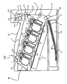
このような中間転写ユニットを有する画像形成装置を図23及び図24に示す。ここで、図23は従来例に係る画像形成装置の断面図であり、図24は従来例に係る画像形成装置の斜視図である。図23に示すように、中間転写ユニット90が画像形成装置本体の一方側から他方側にわたって(例えば、図23の左から右にわたって)配置されている。この中間転写ユニット90のうち、中間転写ベルト91の下方には複数のプロセスカートリッジ93が配置されている。さらに中間転写ユニット90のうち、中間転写ベルトクリーニング装置92は、プロセスカートリッジ93に並設されるように中間転写ベルト91の一方の端部(図23においては左端部)に一体に固定されている。この中間転写ベルトクリーニング装置92が配置された側(図中装置本体の左側)には、図24に示すように、中間転写ユニット90が引き出せるように開口部94が設けられ、この開口部94を覆う開閉部材95が開閉可能に設けられている。これにより、中間転写ユニット90を中間転写ベルトクリーニング装置92側から水平方向に引き出すことができる。   An image forming apparatus having such an intermediate transfer unit is shown in FIGS. FIG. 23 is a cross-sectional view of an image forming apparatus according to a conventional example, and FIG. 24 is a perspective view of the image forming apparatus according to the conventional example. As shown in FIG. 23, the intermediate transfer unit 90 is arranged from one side of the image forming apparatus main body to the other side (for example, from left to right in FIG. 23). In the intermediate transfer unit 90, a plurality of process cartridges 93 are disposed below the intermediate transfer belt 91. Further, in the intermediate transfer unit 90, the intermediate transfer belt cleaning device 92 is integrally fixed to one end portion (left end portion in FIG. 23) of the intermediate transfer belt 91 so as to be arranged in parallel with the process cartridge 93. . As shown in FIG. 24, an opening 94 is provided on the side where the intermediate transfer belt cleaning device 92 is disposed (on the left side of the apparatus main body in the drawing) so that the intermediate transfer unit 90 can be pulled out. An opening / closing member 95 is provided so as to be opened and closed. Accordingly, the intermediate transfer unit 90 can be pulled out in the horizontal direction from the intermediate transfer belt cleaning device 92 side.

特開2001−075374号公報JP 2001-0775374 A

しかしながら、図23及び図24に示す画像形成装置においては、中間転写ユニット90は、中間転写ベルト91に対して中間転写ベルトクリーニング装置92が屈曲した状態で一体に固定されている。このため、中間転写ユニット90を装置本体から引き出すには、プロセスカートリッジ93と干渉しないように、中間転写ベルトクリーニング装置92側からしか引き出せない。すなわち、2つのユニットが一体化された中間転写ユニット90は、一方のユニットである中間転写ベルト91に対して他方のユニットである中間転写ベルトクリーニング装置92の配置が決まると、おのずとそれを引き出す開口部94の配置も決まってしまう。このため、設計の自由度が中間転写ベルトクリーニング装置92の配置によって限定されてしまう。   However, in the image forming apparatus shown in FIGS. 23 and 24, the intermediate transfer unit 90 is fixed integrally with the intermediate transfer belt 91 in a state in which the intermediate transfer belt cleaning device 92 is bent. Therefore, in order to pull out the intermediate transfer unit 90 from the apparatus main body, it can be pulled out only from the intermediate transfer belt cleaning device 92 side so as not to interfere with the process cartridge 93. In other words, the intermediate transfer unit 90 in which the two units are integrated is an opening that naturally draws out the arrangement of the intermediate transfer belt cleaning device 92 that is the other unit relative to the intermediate transfer belt 91 that is one unit. The arrangement of the portion 94 is also determined. For this reason, the degree of freedom in design is limited by the arrangement of the intermediate transfer belt cleaning device 92.

また、中間転写ユニット90の装置本体左側の開口部94から着脱するのに対し、プロセスカートリッジ93及び記録材のカセット96は装置本体前側の実線矢印の方向に着脱する必要がある。また定着手段98は装置本体右側から開閉部材97をあけて破線矢印の方向に着脱する必要がある。このように、ユーザは、メンテナンスのためにさまざまな方向から画像形成装置内部にアクセスせざるを得ず、ユーザビリティの面でも改善の余地がある。そして、このように装置本体の開口部を増やすことは、フレームの剛性を確保する上での障害となり、また、開閉部材が増えるため、低コスト化・省スペース化を実現する上でも技術課題となっている。   Further, while the intermediate transfer unit 90 is attached / detached from the opening 94 on the left side of the apparatus main body, the process cartridge 93 and the recording material cassette 96 need to be attached / detached in the direction of the solid arrow on the front side of the apparatus main body. Further, the fixing means 98 needs to be attached / detached in the direction of the broken line arrow by opening the opening / closing member 97 from the right side of the apparatus main body. Thus, the user is forced to access the inside of the image forming apparatus from various directions for maintenance, and there is room for improvement in terms of usability. Increasing the number of openings in the main body of the apparatus in this way is an obstacle to securing the rigidity of the frame, and since the number of opening and closing members increases, it is also a technical problem in realizing cost reduction and space saving. It has become.

このような背景を踏まえ、本発明の目的は、一体化された2つのユニットの配置関係によって、そのユニットの着脱方向や開口部の位置が限定されないようにし、装置内の他の部材によってユニットの着脱方向が限定されないようにすることである。これにより、画像形成装置の設計の自由度を向上させ、交換が必要なユニットの着脱性という観点で、ユーザビリティを向上させることを課題とする。   In view of such a background, the object of the present invention is to prevent the unit from being attached or detached and the position of the opening portion from being limited by the arrangement relationship of the two integrated units, and by other members in the apparatus. The attachment / detachment direction is not limited. Accordingly, it is an object to improve the usability from the viewpoint of improving the degree of freedom of design of the image forming apparatus and detachability of a unit that needs to be replaced.

前記課題を解決するために、本発明は以下の構成を備える。   In order to solve the above problems, the present invention comprises the following arrangement.

(1)トナー像を担持する像担持体と、前記像担持体からトナー像が転写される、または、トナー像が転写される記録媒体を搬送するエンドレスベルトと、前記エンドレスベルトを張架する複数の張架部材を備える第一のユニットと、前記第一のユニットに当接する第二のユニットと、を備え、画像形成装置本体に対して着脱可能に装着される着脱ユニットと、前記画像形成装置本体に前記着脱ユニットを挿入するための開口部から挿入された前記着脱ユニットを案内するためのガイド部材と、を有する画像形成装置であって、前記着脱ユニットは、前記着脱ユニットを保持するための把手部を備え、前記把手部は、前記着脱ユニットが前記画像形成装置本体に装着されたときには前記着脱ユニットに収納され、前記着脱ユニットが前記画像形成装置本体から離脱したときには前記着脱ユニットから突出し、前記着脱ユニットは、前記第一のユニットに対して前記第二のユニットが移動することによって、第一の姿勢第二の姿勢をとり、前記着脱ユニットが前記ガイド部材に案内されて前記画像形成装置本体に挿入される途中で、前記把手部が突出した状態から収納された状態へと変化することに連動して、前記着脱ユニットが前記第一の姿勢から前記第二の姿勢へと変化することを特徴とする画像形成装置。
(2)像担持体からトナー像が転写される、または、トナー像が転写される記録媒体を搬送するエンドレスベルトと、前記エンドレスベルトを張架する複数の張架部材を備える第一のユニットと、前記第一のユニットに当接する第二のユニットと、を備え、画像形成装置本体に設けられたガイド部材により案内されて前記画像形成装置本体に着脱するための開口部から着脱されるベルトユニットであって、前記ベルトユニットを保持するための把手部を備え、前記把手部は、前記ベルトユニットが前記画像形成装置本体に装着されたときには前記ベルトユニットに収納され、前記ベルトユニットが前記画像形成装置本体から離脱したときには前記ベルトユニットから突出し、前記第一のユニットに対して前記第二のユニットが移動することによって、第一の姿勢と第二の姿勢をとり、前記ベルトユニットが前記ガイド部材に案内されて前記画像形成装置本体に挿入される途中で、前記把手部が突出した状態から収納された状態へと変化することに連動して、前記第一の姿勢から前記第二の姿勢へと変化することを特徴とするベルトユニット。
(1) An image carrier that carries a toner image, an endless belt to which a toner image is transferred or transferred from the image carrier, and a plurality of belts that stretch the endless belt A detachable unit that is detachably attached to the main body of the image forming apparatus, and a first unit that includes a first tension member and a second unit that contacts the first unit; A guide member for guiding the detachable unit inserted from an opening for inserting the detachable unit into a main body, wherein the detachable unit holds the detachable unit. A handle portion, and the handle portion is housed in the detachable unit when the detachable unit is attached to the image forming apparatus main body, and the detachable unit is the image Projecting from said detachable unit is when detached from the forming apparatus main body, wherein the detachable unit is that by the second unit is moved relative to the first unit, taking the first posture and the second posture, the While the detachable unit is guided by the guide member and inserted into the main body of the image forming apparatus, the detachable unit is moved to the retracted state in conjunction with the change of the handle portion from the protruded state. An image forming apparatus that changes from one posture to the second posture.
(2) an endless belt that transfers a toner image from an image carrier or transports a recording medium to which the toner image is transferred, and a first unit that includes a plurality of stretching members that stretch the endless belt; A belt unit that is guided by a guide member provided in the main body of the image forming apparatus and is attached to and detached from an opening for attaching to and detaching from the main body of the image forming apparatus. A grip portion for holding the belt unit, the grip portion being housed in the belt unit when the belt unit is mounted on the image forming apparatus main body, and the belt unit being the image forming portion. Projecting from the belt unit when detached from the apparatus main body, the second unit moves relative to the first unit. Thus, the first posture and the second posture are taken, and the handle unit is housed from the protruding state while the belt unit is guided by the guide member and inserted into the image forming apparatus main body. The belt unit changes from the first posture to the second posture in conjunction with the change to the second posture.

本発明によれば、画像形成装置の設計の自由度を向上させ、交換が必要なユニットの着脱性という観点でユーザビリティを向上させることができる。   According to the present invention, the degree of freedom in designing the image forming apparatus can be improved, and usability can be improved from the viewpoint of detachability of a unit that needs to be replaced.

実施例1に係る画像形成装置の概略断面図1 is a schematic sectional view of an image forming apparatus according to a first embodiment. 実施例1に係る中間転写ユニットの断面図Sectional view of intermediate transfer unit according to Embodiment 1 (a)実施例1に係る中間転写ユニットの斜視図、(b)、(c)中間転写ユニットの把手部の部分拡大図(A) Perspective view of an intermediate transfer unit according to Embodiment 1, (b), (c) Partial enlarged view of a grip portion of the intermediate transfer unit 実施例1に係る中間転写ユニットの上面図Top view of the intermediate transfer unit according to Embodiment 1. (a)実施例1に係る中間転写ユニットの正面図、(b)(a)の転写ベルトクリーニング装置の部分拡大図(A) Front view of intermediate transfer unit according to embodiment 1, (b) Partial enlarged view of transfer belt cleaning device of (a). 実施例1に係る中間転写ユニットの装着部を示す斜視図FIG. 3 is a perspective view illustrating a mounting portion of an intermediate transfer unit according to the first embodiment. 実施例1に係る中間転写ユニットの装着動作を示す斜視図FIG. 6 is a perspective view illustrating the mounting operation of the intermediate transfer unit according to the first embodiment. 実施例1に係る中間転写ユニットの装着動作を示す斜視図FIG. 6 is a perspective view illustrating the mounting operation of the intermediate transfer unit according to the first embodiment. (a)実施例1に係る中間転写ユニットの装着完了状態を示す斜視図、(b)(a)の断面図FIG. 4A is a perspective view illustrating a state in which the intermediate transfer unit according to the first embodiment is mounted, and FIG. (a)実施例1に係る中間転写ユニットの構成を示す斜視図、(b)(a)の要部構成図、(c)テンションローラ軸周辺の部分拡大図(A) Perspective view showing the configuration of the intermediate transfer unit according to the first embodiment, (b) (a) Main part configuration diagram, (c) Partial enlarged view around the tension roller shaft (a)実施例1に係る中間転写ユニットの構成を示す斜視図、(b)(a)の要部構成図(A) Perspective view showing the configuration of the intermediate transfer unit according to the first embodiment, (b) (a) main part configuration diagram of (a). (a)実施例1に係る中間転写ユニットの構成を示す斜視図、(b)(a)の要部構成図(A) Perspective view showing the configuration of the intermediate transfer unit according to the first embodiment, (b) (a) main part configuration diagram of (a). 実施例1に係る中間転写ユニットと装着ガイドを示す部分拡大図Partial enlarged view showing an intermediate transfer unit and a mounting guide according to Embodiment 1. 実施例1に係る中間転写ユニットの装着完了状態を示す断面図Sectional drawing which shows the completion state of mounting | wearing of the intermediate transfer unit which concerns on Example 1. FIG. (a)実施例2に係る中間転写ユニットの構成を示す斜視図、(b)(a)の要部構成図、(c)ラック・アンド・ピニオンの部分拡大図、(d)テンションローラ軸周辺の部分拡大図(A) Perspective view showing the configuration of an intermediate transfer unit according to Example 2, (b) (a) Main part configuration diagram, (c) Partial enlarged view of rack and pinion, (d) Around tension roller shaft Partial enlarged view of (a)実施例2に係る中間転写ユニットの構成を示す斜視図、(b)(a)の要部構成図(A) The perspective view which shows the structure of the intermediate transfer unit which concerns on Example 2, (b) The principal part block diagram of (a). (a)実施例2に係る中間転写ユニットの構成を示す斜視図、(b)(a)の要部構成図、(c)テンションローラ軸周辺の部分拡大図(A) Perspective view showing the configuration of the intermediate transfer unit according to the second embodiment, (b) (a) Main part configuration diagram, (c) Partial enlarged view around the tension roller shaft 実施例3に係る廃トナー回収ユニットの装着動作を示す図で、(a)廃トナー回収ユニットが直線状となっている状態を示す図、(b)(a)の斜視図、(c)廃トナー回収ユニットがヒンジ部を中心に45°回転した状態を示す図、(d)(c)の斜視図、(e)廃トナー回収ユニットがヒンジ部を中心に90°回転した状態を示す図、(f)(e)の斜視図6A and 6B are diagrams illustrating a mounting operation of the waste toner recovery unit according to the third embodiment, where FIG. 5A is a diagram illustrating a state where the waste toner recovery unit is linear, FIG. 5B is a perspective view of FIG. The figure which shows the state which the toner collection unit rotated 45 degrees centering on the hinge part, (d) The perspective view of (c), (e) The figure which shows the state which the waste toner collection unit rotated 90 degrees centering on the hinge part, (F) Perspective view of (e) (a)実施例3に係る廃トナー回収ユニットの装着動作を示す断面図、(b)(a)の斜視図(A) Sectional drawing which shows mounting | wearing operation | movement of the waste toner collection | recovery unit based on Example 3, (b) Perspective view of (a). (a)実施例3に係る廃トナー回収ユニットの装着動作を示す断面図、(b)(a)の斜視図(A) Sectional drawing which shows mounting | wearing operation | movement of the waste toner collection | recovery unit based on Example 3, (b) Perspective view of (a). (a)実施例3に係る廃トナー回収ユニットの装着動作を示す断面図、(b)(a)の斜視図(A) Sectional drawing which shows mounting | wearing operation | movement of the waste toner collection | recovery unit based on Example 3, (b) Perspective view of (a). 実施例3に係る廃トナー回収ユニットの装着動作を示す図で、(a)廃トナー回収ユニットが直線状となっている状態を示す図、(b)廃トナー回収ユニットが弾性変形部で45°に曲がった状態を示す図、(c)廃トナー回収ユニットが弾性変形部で90°に曲がった状態を示す図FIG. 10 is a diagram illustrating a mounting operation of the waste toner recovery unit according to the third embodiment, (a) a diagram illustrating a state in which the waste toner recovery unit is linear, and (b) a waste toner recovery unit having an elastic deformation portion at 45 °. The figure which shows the state bent to (c), (c) The figure which shows the state which the waste toner collection | recovery unit bent to 90 degrees by the elastic deformation part 従来例に係る画像形成装置の断面図Sectional drawing of the image forming apparatus which concerns on a prior art example 従来例に係る画像形成装置の斜視図The perspective view of the image forming apparatus which concerns on a prior art example

以下、図面を参照して、本発明の好適な実施の形態を例示的に詳しく説明する。ただし、以下の実施形態に記載されている構成部品の寸法、材質、形状、それらの相対配置などは、本発明が適用される装置の構成や各種条件により適宜変更されるべきものである。従って、特に特定的な記載がない限りは、本発明の範囲をそれらのみに限定する趣旨のものではない。   Hereinafter, exemplary embodiments of the present invention will be described in detail with reference to the drawings. However, the dimensions, materials, shapes, and relative arrangements of the components described in the following embodiments should be appropriately changed according to the configuration of the apparatus to which the present invention is applied and various conditions. Therefore, unless specifically stated otherwise, the scope of the present invention is not intended to be limited thereto.

図1〜図14を用いて、本実施例に係る画像形成装置について説明する。以下の説明では、まず図1を用いて画像形成装置の全体構成について説明する。次いで図2〜図5を用いて、一次転写ユニットの構成について説明する。次いで図6〜図9を用いて、一次転写ユニットの装置本体への装着動作について説明する。さらに、図10〜図12を用いて、一次転写ユニットの把手部と転写ベルトクリーニング装置の関係を説明する。最後に図7、図9、図14を用いて、一次転写ユニットの装置本体への位置決めについて説明する。   The image forming apparatus according to the present embodiment will be described with reference to FIGS. In the following description, first, the overall configuration of the image forming apparatus will be described with reference to FIG. Next, the configuration of the primary transfer unit will be described with reference to FIGS. Next, the operation of mounting the primary transfer unit on the apparatus main body will be described with reference to FIGS. Further, the relationship between the handle portion of the primary transfer unit and the transfer belt cleaning device will be described with reference to FIGS. Finally, the positioning of the primary transfer unit to the apparatus main body will be described with reference to FIGS. 7, 9, and 14.

[画像形成装置の全体構成]
まず画像形成装置の全体構成について、図1を用いて説明する。図1に示す画像形成装置100は、水平方向に対して傾斜して並設した4個のプロセスカートリッジを有する。そして、プロセスカートリッジ7(7a〜7d)は、それぞれ1個の像担持体としての電子写真感光体ドラム1(1a〜1d)を備えている。
[Entire configuration of image forming apparatus]
First, the overall configuration of the image forming apparatus will be described with reference to FIG. An image forming apparatus 100 shown in FIG. 1 includes four process cartridges arranged in parallel with an inclination with respect to the horizontal direction. Each of the process cartridges 7 (7a to 7d) includes an electrophotographic photosensitive drum 1 (1a to 1d) as one image carrier.

電子写真感光体ドラム(以下、「感光体ドラム」という)1は、駆動部材(不図示)によって、図1中、時計回りに回転駆動される。感光体ドラム1の周囲には、その回転方向に従って順に、感光体ドラム1に作用する以下のプロセス手段2、3、4、5、6が配置されている。まず、感光体ドラム1表面を均一に帯電する帯電ローラ2(2a〜2d)、静電潜像を現像剤であるトナーを用いて現像する現像ユニット4(4a〜4d)が配置されている。そして、転写後の感光体ドラム1表面に残ったトナーを除去するクリーニング部材6(6a〜6d)が配置されている。また、画像情報に基づいてレーザビームを照射し、感光体ドラム1に静電潜像を形成するスキャナユニット3、感光体ドラム1上の4色の現像剤(以下、「トナー」という)画像(トナー像)が一括して転写される中間転写ベルト5が配置されている。ここで、感光体ドラム1と、帯電ローラ2、現像ユニット4及びクリーニング部材6は一体的にカートリッジ化され、画像形成装置の装着部に対して着脱可能なプロセスカートリッジ7を構成している。   An electrophotographic photosensitive drum (hereinafter referred to as “photosensitive drum”) 1 is rotationally driven clockwise in FIG. 1 by a driving member (not shown). Around the photosensitive drum 1, the following process means 2, 3, 4, 5, 6 that act on the photosensitive drum 1 are arranged in order according to the rotation direction. First, a charging roller 2 (2a to 2d) for uniformly charging the surface of the photosensitive drum 1 and a developing unit 4 (4a to 4d) for developing an electrostatic latent image using toner as a developer are arranged. A cleaning member 6 (6a to 6d) for removing the toner remaining on the surface of the photosensitive drum 1 after the transfer is disposed. Further, a laser unit is irradiated on the basis of image information to form an electrostatic latent image on the photosensitive drum 1, and four color developer (hereinafter referred to as “toner”) images on the photosensitive drum 1 (hereinafter referred to as “toner”). An intermediate transfer belt 5 on which toner images are transferred at once is disposed. Here, the photosensitive drum 1, the charging roller 2, the developing unit 4, and the cleaning member 6 are integrally formed as a cartridge to constitute a process cartridge 7 that can be attached to and detached from the mounting portion of the image forming apparatus.

中間転写ベルト5は、駆動ローラ10、テンションローラ11、二次転写対向ローラ33に張架されている。また、各感光体ドラム1(1a〜1d)に対向して、中間転写ベルト5の内側に一次転写ローラ12(12a〜12d)が配設されており、バイアス印加手段(不図示)により転写バイアスを印加する構成となっている。   The intermediate transfer belt 5 is stretched around a driving roller 10, a tension roller 11, and a secondary transfer counter roller 33. Further, a primary transfer roller 12 (12a to 12d) is disposed inside the intermediate transfer belt 5 so as to face each of the photosensitive drums 1 (1a to 1d), and a transfer bias is applied by a bias applying unit (not shown). Is applied.

感光体ドラム1上に形成されたトナー像は、各感光体ドラム1が矢印Q方向に回転し、中間転写ベルト5が矢印R方向に回転し、さらに一次転写ローラ12に正極性のバイアスを印加することにより、順次、中間転写ベルト5上に一次転写される。そして、中間転写ベルト5に4色のトナー像が重なった状態で二次転写部15まで搬送される。   In the toner image formed on the photosensitive drum 1, each photosensitive drum 1 rotates in the arrow Q direction, the intermediate transfer belt 5 rotates in the arrow R direction, and a positive bias is applied to the primary transfer roller 12. As a result, primary transfer is sequentially performed on the intermediate transfer belt 5. Then, the four-color toner images are conveyed to the secondary transfer unit 15 in a state where the intermediate transfer belt 5 is overlaid.

一方、トナー像の転写後に、感光体ドラム1表面に残ったトナーは、クリーニング部材6によって除去され、除去されたトナーは感光体ユニット26(26a〜26d)内の除去トナー室に回収される。   On the other hand, the toner remaining on the surface of the photosensitive drum 1 after the transfer of the toner image is removed by the cleaning member 6, and the removed toner is collected in a removed toner chamber in the photosensitive unit 26 (26a to 26d).

これらの画像形成動作と同期して給送装置13やレジストローラ対17等からなる搬送手段によって記録媒体であるシートが搬送される。給送装置13は、シートSを収納する給送カセット24と、シートSを給送する給送ローラ8と、給送されたシートSを搬送する搬送ローラ対16とを有している。給送カセット24は、図1中の装置手前方向へ引き抜くことができるよう構成されている。ユーザは給送カセット24を引き抜き、装置本体から取り外した後、シートSをセットし装置本体へ挿入することでシート補給が完了する。給送カセット24に収納されたシートSは、給送ローラ8に圧接され、分離パッド9によって一枚ずつ分離され(摩擦片分離方式)、搬送ローラ対16によって搬送される。   In synchronism with these image forming operations, a sheet as a recording medium is conveyed by conveying means including a feeding device 13 and a pair of registration rollers 17. The feeding device 13 includes a feeding cassette 24 that stores the sheet S, a feeding roller 8 that feeds the sheet S, and a conveyance roller pair 16 that conveys the fed sheet S. The feeding cassette 24 is configured so that it can be pulled out toward the front of the apparatus in FIG. After the user pulls out the feeding cassette 24 and removes it from the apparatus main body, the sheet supply is completed by setting the sheet S and inserting it into the apparatus main body. The sheets S stored in the feeding cassette 24 are pressed against the feeding roller 8, separated one by one by the separation pad 9 (friction piece separation method), and conveyed by the conveying roller pair 16.

そして、給送装置13から搬送されたシートSはレジストローラ対17によって二次転写部15に搬送される。二次転写部15において、二次転写ローラ18に正極性のバイアスを印加することにより、搬送されたシートSに、中間転写ベルト5上の4色のトナー像を二次転写する。   Then, the sheet S conveyed from the feeding device 13 is conveyed to the secondary transfer unit 15 by the registration roller pair 17. In the secondary transfer unit 15, a positive bias is applied to the secondary transfer roller 18, whereby the four color toner images on the intermediate transfer belt 5 are secondarily transferred to the conveyed sheet S.

シートSへの二次転写後に中間転写ベルト5上に残ったトナーは、転写ベルトクリーニング装置23によって除去され、除去されたトナーは、廃トナー搬送路(不図示)を通過し、装置左側(図1左側)に配置された廃トナー回収容器46へと回収される。   The toner remaining on the intermediate transfer belt 5 after the secondary transfer to the sheet S is removed by the transfer belt cleaning device 23, and the removed toner passes through a waste toner conveyance path (not shown) and is on the left side of the device (FIG. 1 is collected in a waste toner collecting container 46 disposed on the left side.

一方、定着手段である定着器14は、シートSに形成したトナー像に熱及び圧力を加えて定着させるものである。定着ベルト14aは円筒形状であり、ヒータ等の発熱手段を接着したベルトガイド部材(不図示)にガイドされている。そして、定着ベルト14aと加圧ローラ14bとが所定の圧接力をもって定着ニップ部を形成している。   On the other hand, the fixing device 14 as a fixing unit applies heat and pressure to the toner image formed on the sheet S and fixes the toner image. The fixing belt 14a has a cylindrical shape and is guided by a belt guide member (not shown) to which heat generating means such as a heater is bonded. The fixing belt 14a and the pressure roller 14b form a fixing nip portion with a predetermined pressure contact force.

そして、画像形成部から搬送された未定着トナー像が形成されたシートSが、定着ベルト14aと加圧ローラ14bとの間の定着ニップで加熱及び加圧され、シートS上の未定着トナー像が定着される。その後、定着されたシートSは、排出ローラ対19によって排出トレイ20に排出される。   The sheet S on which the unfixed toner image conveyed from the image forming unit is formed is heated and pressed at the fixing nip between the fixing belt 14a and the pressure roller 14b, and the unfixed toner image on the sheet S is heated. Is established. Thereafter, the fixed sheet S is discharged to the discharge tray 20 by the discharge roller pair 19.

[一次転写ユニットの構成]
次に、図2〜図5を用いて、一次転写ユニットとしての中間転写ユニット101の構成について説明する。図2は中間転写ユニット101の概略断面図、図3は中間転写ユニット101の斜視図、図4は中間転写ユニット101の上面図、図5は中間転写ユニット101の正面図である。
[Configuration of primary transfer unit]
Next, the configuration of the intermediate transfer unit 101 as the primary transfer unit will be described with reference to FIGS. 2 is a schematic sectional view of the intermediate transfer unit 101, FIG. 3 is a perspective view of the intermediate transfer unit 101, FIG. 4 is a top view of the intermediate transfer unit 101, and FIG. 5 is a front view of the intermediate transfer unit 101.

中間転写ユニット101は、第一のユニットである転写ベルトユニット25と、この転写ベルトユニット25に当接して作用する第二のユニットである転写ベルトクリーニング装置23を一体に設けた着脱ユニットである。この中間転写ユニット101は、画像形成装置100本体に対して着脱可能に装着される。   The intermediate transfer unit 101 is a detachable unit in which a transfer belt unit 25 that is a first unit and a transfer belt cleaning device 23 that is a second unit that operates in contact with the transfer belt unit 25 are integrally provided. The intermediate transfer unit 101 is detachably attached to the image forming apparatus 100 main body.

ここで、転写ベルトユニット25は、複数の張架部材である駆動ローラ10、テンションローラ11、二次転写対向ローラ33によって張架されたエンドレスベルトである中間転写ベルト5を有する。さらに転写ベルトユニット25は、中間転写ベルト5を介して各感光体ドラム1と対向する位置に設けられた4本の一次転写ローラ12(12a〜12d)を有する。   Here, the transfer belt unit 25 includes an intermediate transfer belt 5 that is an endless belt that is stretched by a driving roller 10 that is a plurality of stretching members, a tension roller 11, and a secondary transfer counter roller 33. Further, the transfer belt unit 25 has four primary transfer rollers 12 (12 a to 12 d) provided at positions facing the respective photosensitive drums 1 via the intermediate transfer belt 5.

図2に示すように、転写ベルトクリーニング装置23は、中間転写ベルト5に当接して中間転写ベルト5上の残トナーを掻き取るクリーニング部材としてのクリーニングブレード31を有する。また転写ベルトクリーニング装置23は、クリーニングブレード31の姿勢を保持するためのクリーニングブレード支持板32、クリーニングブレード31を中間転写ベルト5に押し付けるためのブレード加圧バネ34を有する。さらに転写ベルトクリーニング装置23は、中間転写ベルト5から除去した残トナーを回収容器に送るためのスクリュウ35などを有する。   As shown in FIG. 2, the transfer belt cleaning device 23 has a cleaning blade 31 as a cleaning member that contacts the intermediate transfer belt 5 and scrapes the residual toner on the intermediate transfer belt 5. The transfer belt cleaning device 23 includes a cleaning blade support plate 32 for maintaining the posture of the cleaning blade 31, and a blade pressure spring 34 for pressing the cleaning blade 31 against the intermediate transfer belt 5. Further, the transfer belt cleaning device 23 includes a screw 35 for sending the residual toner removed from the intermediate transfer belt 5 to a collection container.

転写ベルトクリーニング装置23は、転写ベルトユニット25に対して挿入方向と直交する方向の軸線を中心に揺動可能に設けられている。具体的には、転写ベルトクリーニング装置23は、図3(a)及び図4に示すように、転写ベルトユニット25に対して、テンションローラ11の軸(以下、テンションローラ軸)11a、11bを支点として揺動可能に支持されている。すなわち、転写ベルトクリーニング装置23は、転写ベルトユニット25が有する複数の張架部材のうち、ユニット挿入方向最も奥側(図3(a)の左側)に位置するテンションローラ11の回転中心であるテンションローラ軸11a、11bを中心にして揺動する。   The transfer belt cleaning device 23 is provided so as to be able to swing with respect to the transfer belt unit 25 about an axis line in a direction orthogonal to the insertion direction. Specifically, as shown in FIGS. 3A and 4, the transfer belt cleaning device 23 supports shafts (hereinafter, tension roller shafts) 11 a and 11 b of the tension roller 11 with respect to the transfer belt unit 25. Is supported so as to be swingable. That is, the transfer belt cleaning device 23 is the tension that is the rotation center of the tension roller 11 that is located on the farthest side in the unit insertion direction (left side in FIG. 3A) among the plurality of stretching members of the transfer belt unit 25. It swings around the roller shafts 11a and 11b.

転写ベルトユニット25には、把手部47a、47bが設けられている。把手部47a、47bは回転中心48a(対向側は不図示の48b)を中心に、後述する把手の付勢部材であるねじりコイルばね49a(対向側は不図示の49b)により、図3(b)及び図3(c)の破線矢印(ア)、(イ)の方向にそれぞれ付勢され回動する。   The transfer belt unit 25 is provided with handle portions 47a and 47b. The handle portions 47a and 47b are centered on a rotation center 48a (the opposite side is not shown in FIG. 48b), and a torsion coil spring 49a (the opposite side is not shown in FIG. ) And FIG. 3C and the broken arrows (a) and (b) in FIG.

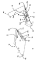
そして、図5(a)に示すように、画像形成装置100本体に装着する前(離脱した状態)と装着完了したとき(装着した状態)とで、転写ベルトユニット25に対する転写ベルトクリーニング装置23の姿勢が異なる。転写ベルトユニット25に対する転写ベルトクリーニング装置23の姿勢は、図5(a)中破線で示す姿勢が挿入開始時(装着前:離脱した状態)の第一の姿勢Aであり、図5(a)中実線で示す姿勢が装着完了時(装着後:装着した状態)の第二の姿勢Bである。このような二つの姿勢をとることで、図5(b)に示す距離L分だけ排紙トレイの高さを下げることが可能となり、排紙積載量を大きくすることが可能となる。また、二つの姿勢をとることで装置自体の高さを低く抑えることが可能になる。   As shown in FIG. 5A, the transfer belt cleaning device 23 with respect to the transfer belt unit 25 is mounted before (detached) from the image forming apparatus 100 main body and when it is completely mounted (mounted). The posture is different. With respect to the posture of the transfer belt cleaning device 23 with respect to the transfer belt unit 25, the posture indicated by a broken line in FIG. 5A is the first posture A at the start of insertion (before mounting: detached state), and FIG. The posture indicated by the solid line is the second posture B when the mounting is completed (after mounting: mounted state). By adopting such two postures, the height of the paper discharge tray can be lowered by the distance L shown in FIG. 5B, and the paper discharge stacking amount can be increased. Moreover, the height of the device itself can be kept low by taking two postures.

また、図4に示すように、転写ベルトクリーニング装置23には、画像形成装置100本体に装着したときの姿勢を決めるための位置決めボス36a、36bが設けられている。転写ベルトユニット25には、中間転写ユニット101を画像形成装置100本体に装着するときの被ガイド部37a、37bが設けられている。図4において、10a、10bは駆動ローラ軸、10c、10dは駆動ローラ軸に取付けられた駆動ローラ軸受である。この転写ベルトクリーニング装置23の位置決めボス36a、36b、中間転写ユニット101の被ガイド部37a、37b、及びテンションローラ軸11a、11bは、後述する画像形成装置100本体内のガイド部材に案内される被ガイド部材である。これらの被ガイド部材は、中間転写ユニット101の挿入方向と直交する方向の両側にそれぞれ設けられている。   As shown in FIG. 4, the transfer belt cleaning device 23 is provided with positioning bosses 36 a and 36 b for determining the posture when the transfer belt cleaning device 23 is attached to the main body of the image forming apparatus 100. The transfer belt unit 25 is provided with guided portions 37 a and 37 b when the intermediate transfer unit 101 is attached to the main body of the image forming apparatus 100. In FIG. 4, 10a and 10b are drive roller shafts, 10c and 10d are drive roller bearings attached to the drive roller shaft. The positioning bosses 36a and 36b of the transfer belt cleaning device 23, the guided portions 37a and 37b of the intermediate transfer unit 101, and the tension roller shafts 11a and 11b are guided by guide members in the main body of the image forming apparatus 100 described later. It is a guide member. These guided members are respectively provided on both sides in a direction orthogonal to the insertion direction of the intermediate transfer unit 101.

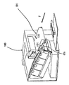
[一次転写ユニットの画像形成装置本体への装着動作]
次に、図6〜図9を用いて、中間転写ユニット101を画像形成装置100本体へ装着する場合の装着動作について説明する。図6は中間転写ユニット101の画像形成装置100本体に装着する装着部を示す斜視図である。図7は中間転写ユニット101の画像形成装置100本体に装着する様子を示す斜視図である。図8は図7に引き続き、中間転写ユニット101が画像形成装置100本体に挿入され、把手部47a、47bが収納され始める様子を示す斜視図である。そして、図9は画像形成装置100本体に中間転写ユニット101が収納完了した様子を示す斜視図と正面図である。
[Mounting operation of the primary transfer unit to the image forming apparatus body]
Next, a mounting operation when the intermediate transfer unit 101 is mounted on the main body of the image forming apparatus 100 will be described with reference to FIGS. FIG. 6 is a perspective view showing a mounting portion that is mounted on the main body of the image forming apparatus 100 of the intermediate transfer unit 101. FIG. 7 is a perspective view showing a state in which the intermediate transfer unit 101 is mounted on the image forming apparatus 100 main body. FIG. 8 is a perspective view illustrating a state in which the intermediate transfer unit 101 is inserted into the main body of the image forming apparatus 100 and the grip portions 47a and 47b begin to be stored, following FIG. FIG. 9 is a perspective view and a front view showing a state in which the intermediate transfer unit 101 is completely stored in the main body of the image forming apparatus 100.

中間転写ユニット101は、画像形成装置100本体に対して、着脱自在に構成されている。このような構成をとることで、例えば中間転写ベルト5もしくは転写ベルトクリーニング装置23などの、修理、点検、交換等のメンテナンス作業が簡易な操作で行えるようになるので、画像形成装置100本体の使い勝手を向上させることができる。   The intermediate transfer unit 101 is configured to be detachable from the image forming apparatus 100 main body. By adopting such a configuration, maintenance work such as repair, inspection, and replacement of the intermediate transfer belt 5 or the transfer belt cleaning device 23 can be performed with a simple operation. Can be improved.

また、画像形成装置100本体の水平方向の寸法を小さくし、画像形成装置100本体の小型化を図るために、図7に示すようにプロセスカートリッジ7は水平方向に対して斜め方向に配置されている。プロセスカートリッジ7の配置にあわせて、中間転写ユニット101も水平方向に対して斜め方向に配置されている。   Further, in order to reduce the horizontal dimension of the main body of the image forming apparatus 100 and reduce the size of the main body of the image forming apparatus 100, the process cartridge 7 is disposed obliquely with respect to the horizontal direction as shown in FIG. Yes. In accordance with the arrangement of the process cartridge 7, the intermediate transfer unit 101 is also arranged obliquely with respect to the horizontal direction.

中間転写ユニット101の画像形成装置100本体に対する装着方向は、図7に示す矢印F方向となる。なお、図1に示す画像形成装置100本体の右側を一次転写ユニットである中間転写ユニット101の装着方向手前側とし、図1の左側を装着方向奥側として以下説明を行う。   The mounting direction of the intermediate transfer unit 101 with respect to the main body of the image forming apparatus 100 is an arrow F direction shown in FIG. The right side of the main body of the image forming apparatus 100 shown in FIG. 1 is the front side in the mounting direction of the intermediate transfer unit 101 as the primary transfer unit, and the left side in FIG.

図6及び図7に示すように、画像形成装置100は、中間転写ユニット101を画像形成装置100本体に挿入するための開口部45を覆う開閉部材38を開閉可能に備えている。   As shown in FIGS. 6 and 7, the image forming apparatus 100 is provided with an opening / closing member 38 that covers an opening 45 for inserting the intermediate transfer unit 101 into the main body of the image forming apparatus 100.

中間転写ユニット101を画像形成装置100本体に装着する際、まず開閉部材38を開く。なお、図6に示すように、二次転写対向ローラ33及びその近傍の搬送ガイドは開閉部材38に設けられており、開閉部材38と一緒に移動する。開閉部材38は画像形成装置100本体の外観面の部位を形成する。また、開閉部材38を開くと、開放された開口部45から、搬送途中で紙詰まり等のジャムが発生したシートSを取り除くことも可能になり、また定着器14の着脱も可能になる。なお、開閉部材38の開閉方向は、上下方向に開閉可能としたが、水平方向に開閉可能な構成であってもよい。   When the intermediate transfer unit 101 is attached to the main body of the image forming apparatus 100, the opening / closing member 38 is first opened. As shown in FIG. 6, the secondary transfer counter roller 33 and the conveyance guide in the vicinity thereof are provided on the opening / closing member 38 and move together with the opening / closing member 38. The opening / closing member 38 forms a portion of the appearance surface of the image forming apparatus 100 main body. Further, when the opening / closing member 38 is opened, it is possible to remove the sheet S in which a jam such as a paper jam has occurred during conveyance from the opened opening 45, and the fixing device 14 can be attached and detached. The opening / closing direction of the opening / closing member 38 can be opened / closed in the vertical direction, but may be configured to be openable / closable in the horizontal direction.

開閉部材38を開くと、画像形成装置100本体の内側に、シートSの搬送路やレジストローラ対17とともに、画像形成装置100本体に対して装着される中間転写ユニット101の装着部39が露出する。   When the opening / closing member 38 is opened, the mounting portion 39 of the intermediate transfer unit 101 mounted on the main body of the image forming apparatus 100 is exposed inside the main body of the image forming apparatus 100 together with the conveyance path of the sheet S and the pair of registration rollers 17. .

図6に点線で示すように、装着部39の画像形成装置100本体の開口部45に向かって左側と右側には、画像形成装置100本体の手前側(図6右側)から奥側(図6左側)に斜め上方向に延びる装着ガイド40、41がそれぞれ設けられる。装着ガイド40、41は、開口部45から装着部39に挿入された中間転写ユニット101を案内するためのガイド部材である。   As shown by a dotted line in FIG. 6, the left side and the right side of the mounting portion 39 toward the opening 45 of the main body of the image forming apparatus 100 are located on the left side and the right side of the main body of the image forming apparatus 100 (the right side in FIG. 6). On the left side, mounting guides 40 and 41 extending obliquely upward are provided. The mounting guides 40 and 41 are guide members for guiding the intermediate transfer unit 101 inserted into the mounting unit 39 from the opening 45.

そして、図7のように中間転写ユニット101の位置決めボス36a、36b、テンションローラ軸11a、11b、被ガイド部37a、37bをそれぞれ順番に装着ガイド40、41にガイドさせつつ、中間転写ユニット101を矢印F方向に挿入する。その後、挿入の途中で、図8に示すがごとく、中間転写ユニット101の把手部47a、47bが画像形成装置100本体のカバーに当接し、図中矢印(ウ)、(エ)の方向に回動し、中間転写ユニット101内に収納され始める。さらに挿入を続けることで、把手部47a、47bは装着ガイド40、41に挟まれる形となり、中間転写ユニット101内に完全に収納される。最終的には、図9のように、中間転写ユニット101を画像形成装置100本体の内部の所定の挿入位置まで挿入した後、開閉部材38を閉じて中間転写ユニット101の装着は完了する。   Then, as shown in FIG. 7, the intermediate transfer unit 101 is guided while the positioning bosses 36a and 36b, the tension roller shafts 11a and 11b, and the guided portions 37a and 37b of the intermediate transfer unit 101 are guided by the mounting guides 40 and 41, respectively. Insert in the direction of arrow F. Thereafter, during the insertion, as shown in FIG. 8, the grip portions 47a and 47b of the intermediate transfer unit 101 abut against the cover of the image forming apparatus 100 main body, and rotate in the directions of arrows (c) and (d) in the figure. And begins to be stored in the intermediate transfer unit 101. By continuing the insertion, the grip portions 47 a and 47 b are sandwiched between the mounting guides 40 and 41 and are completely accommodated in the intermediate transfer unit 101. Finally, as shown in FIG. 9, after the intermediate transfer unit 101 is inserted to a predetermined insertion position inside the main body of the image forming apparatus 100, the opening / closing member 38 is closed to complete the mounting of the intermediate transfer unit 101.

[一次転写ユニットの把手部と転写ベルトクリーニング装置の関係]
図10〜12を用いて、中間転写ユニット101の把手部47a、47bの回動と連動し、転写ベルトクリーニング装置23が揺動する構成について詳細に説明する。
[Relationship between primary transfer unit handle and transfer belt cleaning device]
A configuration in which the transfer belt cleaning device 23 swings in conjunction with the rotation of the grip portions 47a and 47b of the intermediate transfer unit 101 will be described in detail with reference to FIGS.

図10に中間転写ユニット101の装着前の斜視図を図10(a)に、そして、図10(b)は、説明の都合上、把手部47a、47bと転写ベルトクリーニング装置23の揺動動作に関与しないものを図10(a)から除去した図である。把手部47bはそのボス部47bpに可撓性を持つワイヤ52が係止されている。ワイヤ52のもう一端は、転写ベルトユニット25のフレームの一部に設けられたワイヤガイド54と、フレームの開口部51を経由し、転写ベルトクリーニング装置23に具備されたワイヤ保持部53に係止されている。画像形成装置100本体に装着前、把手部47bは前述したように、付勢力を受け、中間転写ユニット101の外側に回動し、突出している。そして、その一部の回転止め部47bfが転写ベルトユニット25のフレームの一部に当接することで、把手部47bの回動量は規制されている。一方、ワイヤ52は、この把手部47bが最も突出したときに、前述した姿勢Aとなるような長さに設定されている。即ち、把手部47bの突出に伴い、ワイヤ52で接続された転写ベルトクリーニング装置23は牽引され、テンションローラ軸11bを回転中心として、姿勢Aに維持・拘束されるわけである。転写ベルトクリーニング装置23は、図10(c)に示すように、転写ベルトユニット25のフレームの一部に形成されたリブ状の回転規制部50mとそれにガイドされる回転規制部50nにより、最大揺動量が所望の量となるような構成をとっている。回転規制部50nは、転写ベルトクリーニング装置23に設けられている。   FIG. 10A is a perspective view before the intermediate transfer unit 101 is mounted, and FIG. 10B is a swing operation of the grip portions 47a and 47b and the transfer belt cleaning device 23 for convenience of explanation. It is the figure which removed from FIG. The handle portion 47b has a flexible wire 52 locked to the boss portion 47bp. The other end of the wire 52 is locked to a wire holding portion 53 provided in the transfer belt cleaning device 23 via a wire guide 54 provided in a part of the frame of the transfer belt unit 25 and an opening 51 of the frame. Has been. Before being attached to the main body of the image forming apparatus 100, the handle portion 47 b receives an urging force as described above, and rotates and protrudes outside the intermediate transfer unit 101. The rotation amount of the grip portion 47b is regulated by the partial rotation stop portion 47bf coming into contact with a part of the frame of the transfer belt unit 25. On the other hand, the wire 52 is set to have such a length as to be in the posture A described above when the handle portion 47b protrudes most. That is, with the protrusion of the handle 47b, the transfer belt cleaning device 23 connected by the wire 52 is pulled and maintained and restrained in the posture A around the tension roller shaft 11b. As shown in FIG. 10 (c), the transfer belt cleaning device 23 has a rib-shaped rotation restricting portion 50m formed on a part of the frame of the transfer belt unit 25 and a rotation restricting portion 50n guided by the rib-like rotation restricting portion 50n. The configuration is such that the amount of movement is a desired amount. The rotation restricting portion 50n is provided in the transfer belt cleaning device 23.

引き続き、把手部47a、47bが中間転写ユニット101内に収納されるときの転写ベルトクリーニング装置23の姿勢について説明する。図11は中間転写ユニット101が画像形成装置100本体に装着される途中の状態、図12は装着完了後の図である。図中の(a)及び(b)は図10と同様、それぞれのタイミングでの中間転写ユニット101の斜視図及び関連要素の図である。   Next, the posture of the transfer belt cleaning device 23 when the grip portions 47a and 47b are housed in the intermediate transfer unit 101 will be described. FIG. 11 is a state in the middle of mounting the intermediate transfer unit 101 to the image forming apparatus 100 main body, and FIG. 12 is a view after the mounting is completed. (A) and (b) in the drawing are a perspective view of the intermediate transfer unit 101 at each timing and a diagram of related elements, as in FIG.

前述したように、中間転写ユニット101が画像形成装置100本体への装着動作されるとき、把手部47a、47bは画像形成装置100本体に当接しながら、収納され始める。すなわち、図11(a)に示すように、中間転写ユニット101に対し図中矢印(オ)、(カ)の方向に回動しながら収納され始める。同時に、把手部47bが図中矢印(キ)の方向に回動すると、把手部47bに接続されたワイヤ52のテンションが弱まり、転写ベルトクリーニング装置23は、その自重により、図11(b)の矢印(ク)のように揺動し始めようとする。   As described above, when the intermediate transfer unit 101 is mounted on the main body of the image forming apparatus 100, the grip portions 47a and 47b start to be accommodated while being in contact with the main body of the image forming apparatus 100. That is, as shown in FIG. 11A, the intermediate transfer unit 101 starts to be stored while being rotated in the directions indicated by arrows (e) and (f). At the same time, when the handle portion 47b is rotated in the direction of the arrow (K) in the drawing, the tension of the wire 52 connected to the handle portion 47b is weakened, and the transfer belt cleaning device 23 has its own weight, so that the transfer belt cleaning device 23 in FIG. Try to start swinging as shown by the arrow (c).

さらに、中間転写ユニット101が画像形成装置100本体へ挿入されると、把手部47a、47bは図12(a)の中間転写ユニット101内に、矢印(ケ)、(コ)のように完全に収納される。この時、図12(b)のように、把手部47bが図中破線矢印(ナ)の方向に回動し、ワイヤ52のテンションはなくなり、転写ベルトクリーニング装置23はさらに矢印(サ)に示す方向に揺動し、先に述べた回転規制部50m、50nによりその揺動が止まる。なお、この時、回転規制部50m、50nの規制の中においては、揺動は規制されない。   Further, when the intermediate transfer unit 101 is inserted into the main body of the image forming apparatus 100, the grip portions 47a and 47b are completely inserted into the intermediate transfer unit 101 in FIG. Stored. At this time, as shown in FIG. 12B, the handle 47b is rotated in the direction of the broken line arrow (n) in the figure, the tension of the wire 52 is lost, and the transfer belt cleaning device 23 is further indicated by the arrow (s). Oscillate in the direction, and the oscillation is stopped by the rotation restricting portions 50m and 50n described above. At this time, the swing is not restricted in the restriction of the rotation restricting portions 50m and 50n.

以上で述べたように、転写ベルトユニット25に対し、転写ベルトクリーニング装置23が揺動する構成をとることで、装置の小型化が実現できる。しかし、その一方で、図13に示すように装着ガイド40、41の入り口幅Jに対し、転写ベルトクリーニング装置23の揺動量Kが大きくなる。このため、使用者が中間転写ユニット101を画像形成装置100本体に挿入し始めるときに、挿入位置が定まらず、挿入し難くなる恐れがある。もちろん、装着ガイド40、41の入り口自体を大きくしたり、面取り部を大きくしたりする対策が考えられる。しかしながら、本来画像形成の大きな役割を担う中間転写ユニット101や定着器14に必要なスペースに影響したり、装置そのものが大きくなってしまったりすることが懸念される。   As described above, by adopting a configuration in which the transfer belt cleaning device 23 swings with respect to the transfer belt unit 25, the size of the device can be reduced. However, on the other hand, as shown in FIG. 13, the swing amount K of the transfer belt cleaning device 23 becomes larger than the entrance width J of the mounting guides 40 and 41. For this reason, when the user starts to insert the intermediate transfer unit 101 into the main body of the image forming apparatus 100, the insertion position is not fixed and it may be difficult to insert. Of course, measures to enlarge the entrances themselves of the mounting guides 40 and 41 or to enlarge the chamfered portion can be considered. However, there is a concern that the space necessary for the intermediate transfer unit 101 and the fixing device 14 that originally play a large role in image formation may be affected, or the apparatus itself may become large.

これに対し、上述したように、転写ベルトユニット25に対し、転写ベルトクリーニング装置23が揺動する構成をとり、さらに、把手部47a、47bと転写ベルトクリーニング装置23の揺動を連携させる。こうすることで、従来の装着ガイド40、41や中間転写ユニット101が占めるスペースを殆ど大きくすることなく、かつユニットの装着時のユーザビリティを確保した画像形成装置の構成が実現できる。   On the other hand, as described above, the transfer belt cleaning device 23 swings with respect to the transfer belt unit 25, and the swinging of the grip portions 47a and 47b and the transfer belt cleaning device 23 is linked. By doing so, it is possible to realize the configuration of the image forming apparatus that ensures the usability when the unit is mounted without increasing the space occupied by the conventional mounting guides 40 and 41 and the intermediate transfer unit 101.

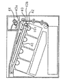
[一次転写ユニットの装置本体への位置決め]
次に、図7・図9・図14を用いて、中間転写ユニット101の画像形成装置100本体に対する位置決めに関して、さらに詳しく説明する。
[Positioning of the primary transfer unit to the main unit]
Next, the positioning of the intermediate transfer unit 101 with respect to the main body of the image forming apparatus 100 will be described in more detail with reference to FIGS. 7, 9, and 14.

なお、以下の説明では、画像形成装置100本体の図7等の紙面手前側の装着ガイド40に対する中間転写ユニット101の本体手前側の位置決めに関して説明する。画像形成装置100本体及び中間転写ユニット101の本体奥側(図7等の紙面奥側の不図示の部分)にも手前側と対称形状の装着ガイド41及び被ガイド部材が設けられている。そして、中間転写ユニット101は画像形成装置100本体の図中手前と奥側で傾きを生じることなく装着される構成となっている。   In the following description, the positioning of the intermediate transfer unit 101 on the front side of the main body with respect to the mounting guide 40 on the front side of the sheet of FIG. On the back side of the main body of the image forming apparatus 100 and the intermediate transfer unit 101 (not shown) on the back side of the paper surface in FIG. The intermediate transfer unit 101 is mounted without causing an inclination between the front and back sides of the image forming apparatus 100 main body in the drawing.

中間転写ユニット101を装着する前、転写ベルトユニット25に対する転写ベルトクリーニング装置23は、上述したように、把手部47a、47bの回転、突出に伴い、転写ベルトクリーニング装置23が図5の姿勢Aをとる。このため、図7に示すようにユニット下面がほぼ平面となるような略直線上の第一の姿勢をとる。   Before the intermediate transfer unit 101 is mounted, the transfer belt cleaning device 23 with respect to the transfer belt unit 25 has the posture A in FIG. 5 in accordance with the rotation and protrusion of the grip portions 47a and 47b as described above. Take. For this reason, as shown in FIG. 7, it takes the 1st attitude | position on a substantially straight line so that a unit lower surface may become a substantially plane.

図9(b)に示すように、画像形成装置100本体の装着部39に設けられた装着ガイド40は、挿入方向上流側から下流側に向けて順に、第一ガイド部40b、第二ガイド部40d、第三ガイド部40fを有している。この3つのガイド部は、装着ガイド40が各被ガイド部材を挟み込む幅が挿入方向下流側に向けて段階的に狭くなるように形成されている。このうち、第二ガイド部40dは第一ガイド部40bよりも幅が狭く、テンションローラ軸11aを嵌合する幅を有している。また、第三ガイド部40fは、第二ガイド部40dよりも幅が狭く、位置決めボス36aを嵌合する幅を有している。   As shown in FIG. 9B, the mounting guide 40 provided in the mounting portion 39 of the main body of the image forming apparatus 100 has a first guide portion 40b and a second guide portion in order from the upstream side in the insertion direction to the downstream side. 40d and a third guide portion 40f. The three guide portions are formed such that the width in which the mounting guide 40 sandwiches each guided member narrows stepwise toward the downstream side in the insertion direction. Among these, the second guide portion 40d is narrower than the first guide portion 40b and has a width for fitting the tension roller shaft 11a. The third guide portion 40f is narrower than the second guide portion 40d and has a width for fitting the positioning boss 36a.

中間転写ユニット101を画像形成装置100本体に装着するときは、図7に示すように、まず転写ベルトクリーニング装置23の位置決めボス36aを装着ガイド40の入口部40aにあわせる。そして、位置決めボス36aを装着ガイド40の第一ガイド部40bの下側面に沿わせて中間転写ユニット101を矢印F方向に挿入していくと、次いでテンションローラ軸11aが装着ガイド40の第一ガイド部40bにガイドされる。そしてさらに中間転写ユニット101を矢印F方向に押すと、転写ベルトユニット25の被ガイド部37aが装着ガイド40の第一ガイド部40bにガイドされる。   When the intermediate transfer unit 101 is mounted on the main body of the image forming apparatus 100, first, the positioning boss 36a of the transfer belt cleaning device 23 is aligned with the inlet 40a of the mounting guide 40 as shown in FIG. Then, when the intermediate transfer unit 101 is inserted in the direction of the arrow F with the positioning boss 36 a along the lower surface of the first guide portion 40 b of the mounting guide 40, the tension roller shaft 11 a is then moved to the first guide of the mounting guide 40. Guided by the portion 40b. When the intermediate transfer unit 101 is further pushed in the direction of arrow F, the guided portion 37 a of the transfer belt unit 25 is guided by the first guide portion 40 b of the mounting guide 40.

そのまま中間転写ユニット101を矢印F方向に押し続けると、転写ベルトクリーニング装置23の位置決めボス36aが装着ガイド40の第二ガイド部40dの屈曲部40eに達する。その後、図9(b)に示すように、位置決めボス36aが装着ガイド40の第二ガイド部40dに案内されて、転写ベルトクリーニング装置23がテンションローラ軸11aを中心に徐々に揺動して姿勢を変え始める。なお、この時、把手部47a、47bは既に中間転写ユニット101内に収納され、転写ベルトクリーニング装置23の揺動が規制されてはいないので、装着ガイド40による転写ベルトクリーニング装置23の姿勢変化を妨げることはない。   If the intermediate transfer unit 101 is continuously pushed in the direction of arrow F, the positioning boss 36a of the transfer belt cleaning device 23 reaches the bent portion 40e of the second guide portion 40d of the mounting guide 40. Thereafter, as shown in FIG. 9B, the positioning boss 36a is guided by the second guide portion 40d of the mounting guide 40, and the transfer belt cleaning device 23 gradually swings around the tension roller shaft 11a. Start changing. At this time, since the grip portions 47a and 47b are already accommodated in the intermediate transfer unit 101 and the swinging of the transfer belt cleaning device 23 is not restricted, the posture change of the transfer belt cleaning device 23 by the mounting guide 40 is changed. There is no hindrance.

そして、中間転写ユニット101が画像形成装置100本体に装着完了する直前に、図14に示すように、駆動ローラ軸10aに取付けられた駆動ローラ軸受10cが、画像形成装置100本体に設けられたロックレバー43に接する位置に到達する。   Then, immediately before the intermediate transfer unit 101 is completely attached to the main body of the image forming apparatus 100, as shown in FIG. 14, the driving roller bearing 10c attached to the driving roller shaft 10a is locked to the main body of the image forming apparatus 100. It reaches a position in contact with the lever 43.

ロックレバー43は画像形成装置100本体側に設けられ、回動中心43aを中心に回動する。そして、ロックレバー43は、回動中心43aを中心にして、ロックレバーバネ44によって矢印G方向に付勢されている。   The lock lever 43 is provided on the main body side of the image forming apparatus 100 and rotates around the rotation center 43a. The lock lever 43 is biased in the direction of arrow G by the lock lever spring 44 around the rotation center 43a.

駆動ローラ軸受10cがロックレバー43に接する位置に到達してから、中間転写ユニット101をさらに矢印F方向に押すと、ロックレバー43は駆動ローラ軸受10cから力を受けて矢印G方向と反対の方向に回動しながら退避する。そして駆動ローラ軸受10cがロックレバー43の頂点43bを通過すると、ロックレバー43はロックレバーバネ44の付勢力により、駆動ローラ軸受10cに沿いながら矢印G方向に回動する。   If the intermediate transfer unit 101 is further pushed in the direction of arrow F after the drive roller bearing 10c reaches a position where it contacts the lock lever 43, the lock lever 43 receives a force from the drive roller bearing 10c and is in a direction opposite to the arrow G direction. Retract while rotating. When the drive roller bearing 10c passes the apex 43b of the lock lever 43, the lock lever 43 rotates in the direction of arrow G along the drive roller bearing 10c by the urging force of the lock lever spring 44.

駆動ローラ軸受10cが画像形成装置100本体に設けられた位置決め部42に突き当たった所で、中間転写ユニット101は止まり、装着完了となる。そして、ロックレバー43は駆動ローラ軸受10cを位置決め部42に押し付けながら、中間転写ユニット101を画像形成装置100本体に固定している。   When the driving roller bearing 10c hits the positioning portion 42 provided in the main body of the image forming apparatus 100, the intermediate transfer unit 101 stops and the mounting is completed. The lock lever 43 fixes the intermediate transfer unit 101 to the main body of the image forming apparatus 100 while pressing the driving roller bearing 10 c against the positioning portion 42.

このとき、テンションローラ軸11aは装着ガイド40の第二ガイド部40dに到達し、中間転写ユニット101の装着方向と略垂直方向に嵌合状態となる。これにより、中間転写ユニット101のうちの転写ベルトユニット25の位置が決まる。また、転写ベルトクリーニング装置23は位置決めボス36aが装着ガイド40の第三ガイド部40fに到達して嵌合状態となる。これにより、転写ベルトクリーニング装置23は、テンションローラ軸11aを回動中心とした揺動が止まり、装着前の第一の姿勢とは異なる第二の姿勢に変化し終えて、図9(b)に示すように位置が決まる。このように、中間転写ユニット101をなす転写ベルトユニット25と転写ベルトクリーニング装置23は、装着ガイド40(41)によって各々画像形成装置100本体に位置決めがなされる。   At this time, the tension roller shaft 11a reaches the second guide portion 40d of the mounting guide 40 and is in a fitted state in a direction substantially perpendicular to the mounting direction of the intermediate transfer unit 101. Thereby, the position of the transfer belt unit 25 in the intermediate transfer unit 101 is determined. Further, the transfer belt cleaning device 23 is brought into a fitted state when the positioning boss 36 a reaches the third guide portion 40 f of the mounting guide 40. As a result, the transfer belt cleaning device 23 stops swinging about the tension roller shaft 11a as the center of rotation, and finishes changing to a second posture different from the first posture before mounting, and FIG. The position is determined as shown in FIG. As described above, the transfer belt unit 25 and the transfer belt cleaning device 23 constituting the intermediate transfer unit 101 are each positioned in the main body of the image forming apparatus 100 by the mounting guide 40 (41).

上述したように、中間転写ユニット101は、転写ベルトユニット25に対して転写ベルトクリーニング装置23が揺動可能に一体化されている。これにより、中間転写ユニット101は、装着過程において転写ベルトユニット25に対して転写ベルトクリーニング装置23の姿勢が装着ガイド40、41にならって変化する。このため、一体化された2つのユニットである転写ベルトクリーニング装置23、転写ベルトユニット25の配置関係によって、中間転写ユニット101の着脱方向や開口部の位置が限定されることはない。さらに、装置内のプロセスカートリッジなどの部材によって中間転写ユニット101の着脱方向が限定されることもない。これにより、設計の自由度が向上する。   As described above, the intermediate transfer unit 101 is integrated with the transfer belt unit 25 so that the transfer belt cleaning device 23 can swing. As a result, the posture of the transfer belt cleaning device 23 with respect to the transfer belt unit 25 changes in accordance with the attachment guides 40 and 41 in the intermediate transfer unit 101 during the attachment process. For this reason, the mounting / removal direction of the intermediate transfer unit 101 and the position of the opening are not limited by the arrangement relationship between the transfer belt cleaning device 23 and the transfer belt unit 25 which are two integrated units. Further, the attaching / detaching direction of the intermediate transfer unit 101 is not limited by a member such as a process cartridge in the apparatus. Thereby, the freedom degree of design improves.

また、転写ベルトユニット25に対して転写ベルトクリーニング装置23が揺動可能に一体化した中間転写ユニット101とすることにより、中間転写ユニット101を転写ベルトユニット25側から引き出すことができる。これにより、ユニット着脱のための開口部の開閉部材38は、シートSのジャム処理のための開閉部材と定着器交換のための開閉部材を兼ねて使うことができる。   Further, by using the intermediate transfer unit 101 in which the transfer belt cleaning device 23 is swingably integrated with respect to the transfer belt unit 25, the intermediate transfer unit 101 can be pulled out from the transfer belt unit 25 side. As a result, the opening / closing member 38 of the opening for attaching / detaching the unit can be used as an opening / closing member for jamming the sheet S and an opening / closing member for replacing the fixing device.

なお、前述した形態では、画像形成装置本体に対して着脱自在なプロセスカートリッジを4つ使用しているが、この使用個数は限定されるものではなく、必要に応じて適宜設定すれば良い。また、ガイド部材は、前述した形態のようなレール形状のものに限定するものではなく、本体内部の突起等、第一のユニットに対する第二のユニットの姿勢を変化させる他の部材でも良い。   In the above-described embodiment, four process cartridges that can be attached to and detached from the image forming apparatus main body are used. However, the number of the process cartridges is not limited, and may be set as necessary. Further, the guide member is not limited to the rail shape as in the above-described form, and may be another member that changes the posture of the second unit relative to the first unit, such as a protrusion inside the main body.

また前述した形態では、感光体ドラムと、この感光体ドラムに作用するプロセス手段としての帯電手段(帯電ローラ2)、現像手段(現像ユニット4)、クリーニング手段(クリーニング部材6)を一体に有するプロセスカートリッジを例示した。しかしながら、これに限定されるものではなく、感光体ドラムの他に、帯電手段、現像手段、クリーニング手段のうち、いずれか1つを一体に有するプロセスカートリッジであっても良い。   Further, in the above-described embodiment, a process including a photosensitive drum, and a charging unit (charging roller 2), a developing unit (developing unit 4), and a cleaning unit (cleaning member 6) as process units acting on the photosensitive drum. A cartridge was illustrated. However, the process cartridge is not limited to this, and may be a process cartridge integrally including any one of a charging unit, a developing unit, and a cleaning unit in addition to the photosensitive drum.

実施例1では、転写ベルトユニット25に対して、ワイヤ52を用いて転写ベルトクリーニング装置23の揺動とその姿勢を拘束する構成を実施例として提示した。これに対し、把手部47a、47bと転写ベルトクリーニング装置23とをラック・アンド・ピニオン(ラック&ピニオン)機構で連動させることも可能である。図15〜17を用いて、この場合の構成について説明する。   In the first embodiment, the configuration in which the transfer belt cleaning device 23 is restrained from swinging and its posture using the wire 52 with respect to the transfer belt unit 25 is presented as an embodiment. On the other hand, the grip portions 47a and 47b and the transfer belt cleaning device 23 can be interlocked by a rack and pinion (rack and pinion) mechanism. The configuration in this case will be described with reference to FIGS.

図15〜図17は図10〜図12と同様、ラック55a、55b及びピニオン56とからなる機構を用いて、中間転写ユニット101の把手部47a、47bの回動と連動し、転写ベルトクリーニング装置23が揺動する構成について詳細に説明する。   15 to 17 are similar to FIGS. 10 to 12, using a mechanism including racks 55 a and 55 b and a pinion 56, and in conjunction with the rotation of the grip portions 47 a and 47 b of the intermediate transfer unit 101, the transfer belt cleaning device. The configuration in which the 23 swings will be described in detail.

図15(a)は中間転写ユニット101の装着前の斜視図、そして、図15(b)は、説明の都合上、把手部47a、47bと転写ベルトクリーニング装置23の動作関係に関与しないものを図15(a)から除去した図である。図15(c)はピニオン56を示す部分拡大図である。図15(d)はラック55bのカム部55baを、そして、転写ベルトクリーニング装置23の被ガイド部であるボス部23aの関係を示す部分拡大図である。転写ベルトユニット25のフレームの一部に設けられたラック保持部57があり、これに図15(b)の実線矢印の方向にラック55a、55bがピニオン56とともに取付けられている。ラック55aはラック保持部57の一部に形成されたばね保持部57aに取付けられた圧縮ばね58により、図15(b)の破線矢印(シ)の方向に付勢されている。ラック55aは、もう一対のラック55bの穴55bcの端部がテンションローラ軸11bに当接するまで矢印(シ)の方向に移動して止まる。そうすると、ラック55bのカム部55baは、転写ベルトクリーニング装置23の被ガイド部であるボス部23aと図15(d)に示すような関係をとり、転写ベルトクリーニング装置23は図5の第一の姿勢Aをとる。   FIG. 15A is a perspective view before the intermediate transfer unit 101 is mounted, and FIG. 15B is a diagram that does not relate to the operation relationship between the grip portions 47a and 47b and the transfer belt cleaning device 23 for convenience of explanation. It is the figure removed from Fig.15 (a). FIG. 15C is a partially enlarged view showing the pinion 56. FIG. 15D is a partially enlarged view showing the relationship between the cam portion 55ba of the rack 55b and the boss portion 23a which is a guided portion of the transfer belt cleaning device 23. There is a rack holding portion 57 provided at a part of the frame of the transfer belt unit 25, and racks 55a and 55b are attached together with the pinion 56 in the direction of the solid arrow in FIG. The rack 55a is urged in the direction of the broken line arrow (f) in FIG. 15 (b) by a compression spring 58 attached to a spring holding part 57a formed in a part of the rack holding part 57. The rack 55a stops moving in the direction of the arrow until the end of the hole 55bc of the other pair of racks 55b contacts the tension roller shaft 11b. Then, the cam portion 55ba of the rack 55b has a relationship as shown in FIG. 15D with the boss portion 23a which is a guided portion of the transfer belt cleaning device 23, and the transfer belt cleaning device 23 is the first in FIG. Take posture A.

続いて、把手部47a、47bが中間転写ユニット101内に収納されるときの転写ベルトクリーニング装置23の姿勢について説明する。図16は中間転写ユニット101が画像形成装置100本体に装着される途中の状態、図17は装着完了後の図である。図中の(a)及び(b)は図15と同様、それぞれのタイミングでの中間転写ユニット101の斜視図及び関連要素の図である。   Next, the posture of the transfer belt cleaning device 23 when the grip portions 47a and 47b are housed in the intermediate transfer unit 101 will be described. 16 is a state in the middle of mounting the intermediate transfer unit 101 to the main body of the image forming apparatus 100, and FIG. 17 is a view after the mounting is completed. (A) and (b) in the figure are a perspective view of the intermediate transfer unit 101 at each timing and a diagram of related elements, as in FIG.

前述したように、中間転写ユニット101が画像形成装置100本体への装着動作されるとき、把手部47a、47bは次のようにして収納され始める。すなわち、把手部47a、47bは、画像形成装置100本体に当接しながら、図16(a)のように、中間転写ユニット101に対し図中矢印(ス)、(セ)の方向に回動しながら収納され始める。そして、把手部47bは図中破線矢印(ソ)の方向に回動してラック55aに設けられた当接部55abに当接し、ラック55aは圧縮ばね58の付勢力に抗しながら、図16(b)の実線矢印の方向にスライドし始める。さらに、中間転写ユニット101が画像形成装置100本体へ挿入されると、把手部47a、47bは図17(a)中間転写ユニット101内に完全に収納される。このとき、図17(b)のように、ラック55aは把手部47aからの力を受け、矢印(タ)の方向にスライドし、ピニオン56が矢印(チ)の方向に回転し、さらに、ラック55bが矢印(ツ)の方向にスライドする。そして、ラック55bのカム部55baは、転写ベルトクリーニング装置23の被ガイド部であるボス部23aと図17(c)に示すような関係をとり、転写ベルトクリーニング装置23は図5の第二の姿勢Bをとるのである。   As described above, when the intermediate transfer unit 101 is mounted on the main body of the image forming apparatus 100, the grip portions 47a and 47b start to be stored as follows. That is, the grip portions 47a and 47b are rotated in the directions of arrows (s) and (s) in the drawing with respect to the intermediate transfer unit 101 as shown in FIG. It begins to be stored while. Then, the handle portion 47b rotates in the direction of the broken line arrow (so) in the drawing and comes into contact with the contact portion 55ab provided in the rack 55a. The rack 55a resists the urging force of the compression spring 58, while FIG. It begins to slide in the direction of the solid arrow in (b). Further, when the intermediate transfer unit 101 is inserted into the main body of the image forming apparatus 100, the grip portions 47a and 47b are completely accommodated in the intermediate transfer unit 101 in FIG. At this time, as shown in FIG. 17B, the rack 55a receives the force from the handle portion 47a, slides in the direction of arrow (t), the pinion 56 rotates in the direction of arrow (h), 55b slides in the direction of the arrow. The cam portion 55ba of the rack 55b has a relationship as shown in FIG. 17C with the boss portion 23a which is a guided portion of the transfer belt cleaning device 23, and the transfer belt cleaning device 23 is the second portion of FIG. The posture B is taken.

このように、転写ベルトクリーニング装置23はそのボス部23aがラック55bのカム部55baにより移動範囲が規制される(図の矢印方向で量M)ので、その揺動範囲は規定される。ただし、その規制の中では自由に揺動できるようになっている。それゆえ、実施例1と同様、画像形成装置100本体内の装着ガイド40、41の形状に沿って、画像形成装置100本体内に中間転写ユニット101は収納可能となっている。なお、転写ベルトユニット25に対する転写ベルトクリーニング装置23の揺動構成以外は実施例1と何ら変えることなく本実施例は実現可能である。具体的には、画像形成装置100の本体構成及び画像形成動作、画像形成装置100本体内への転写ベルトユニット25の着脱方法や、位置決めなどは実施例1と何ら変えることなく本実施例は実現可能である。このため、それらの説明は割愛する。   As described above, the movement range of the transfer belt cleaning device 23 is regulated by the cam portion 55ba of the rack 55b (the amount M in the direction of the arrow in the figure), so that the swing range is defined. However, it can swing freely within the regulations. Therefore, as in the first embodiment, the intermediate transfer unit 101 can be accommodated in the image forming apparatus 100 main body along the shape of the mounting guides 40 and 41 in the image forming apparatus 100 main body. The present embodiment can be realized without any change from the first embodiment except for the swing configuration of the transfer belt cleaning device 23 with respect to the transfer belt unit 25. Specifically, the configuration of the main body and the image forming operation of the image forming apparatus 100, the method of attaching and detaching the transfer belt unit 25 to and from the main body of the image forming apparatus 100, positioning, and the like are realized without any change from the first embodiment. Is possible. For this reason, those explanations are omitted.

実施例1及び2では、画像形成装置100は、転写ベルトクリーニング装置23が転写ベルトユニット25に対し揺動する構成とした。そして、把手部47a、47bと連動しその揺動量が規制される中間転写ユニット101を用いた、記録画像を形成する画像形成装置であるとして説明した。しかし、本発明は中間転写ユニット101に限定されるものではない。   In the first and second embodiments, the image forming apparatus 100 is configured such that the transfer belt cleaning device 23 swings with respect to the transfer belt unit 25. The image forming apparatus has been described as an image forming apparatus that forms a recorded image using the intermediate transfer unit 101 that is interlocked with the grip portions 47a and 47b and whose swing amount is regulated. However, the present invention is not limited to the intermediate transfer unit 101.

例えば、転写ベルトクリーニング装置23が回収した廃トナー回収容器46などにも適用が可能である。以下、図18〜図22を用いて、この場合の実施例について説明する。なお、以下では、実施例2と同様、画像形成装置100の本体構成及び画像形成動作については説明を省略する。   For example, the present invention can also be applied to a waste toner collection container 46 collected by the transfer belt cleaning device 23. Hereinafter, an embodiment in this case will be described with reference to FIGS. Hereinafter, as in the second embodiment, description of the main body configuration and the image forming operation of the image forming apparatus 100 is omitted.

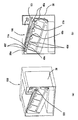
図18に第一容器60と第二容器61からなる廃トナー回収ユニット64を示す。(a)・(b)、(c)・(d)、(e)・(f)の組み合わせでは、それぞれ、廃トナー回収ユニット64が直線状から、第一容器60と第二容器61を回動可能に接続しているヒンジ部63を中心に45°、90°回転し、その姿勢を変える様子を示している。図中(a)・(c)・(e)が正面図、(b)・(d)・(f)が斜視図である。   FIG. 18 shows a waste toner collecting unit 64 including a first container 60 and a second container 61. In the combinations of (a), (b), (c), (d), (e), and (f), the waste toner collection unit 64 is rotated straight from the first container 60 and the second container 61, respectively. It shows a state in which the posture is changed by rotating 45 ° and 90 ° around the hinge portion 63 that is movably connected. In the drawing, (a), (c), and (e) are front views, and (b), (d), and (f) are perspective views.

廃トナー回収ユニット64は中間転写ユニット101から排出された廃トナーを、転写ベルトクリーニング装置23を経由し、不図示の搬送路を介し回収する。第一容器60と第二容器61は容器内で接続されており、廃トナーは第一容器60と第二容器61の双方の容積が満たされるまで回収可能である。   The waste toner collection unit 64 collects the waste toner discharged from the intermediate transfer unit 101 via the transfer belt cleaning device 23 and a conveyance path (not shown). The first container 60 and the second container 61 are connected in the container, and the waste toner can be collected until both the volumes of the first container 60 and the second container 61 are filled.

廃トナー回収ユニット64には、第一容器60と第二容器61を繋いでいる可撓性の把手62が設けられている。把手は第一容器60と第二容器61にそれぞれ設けられた、把手ガイド部60c、61c、61dにより、廃トナー回収ユニット64を着脱する際に図18のように外れることなく、移動することができるようになっている。そして、着脱時に把手62が引っ張られると、図18(a)、図18(b)のように把手62の一部のテーパー形状のテーー部62aが、第二容器のテーパー部61eと係合し、廃トナー回収ユニット64を直線状に維持する。 The waste toner collecting unit 64 is provided with a flexible handle 62 that connects the first container 60 and the second container 61. The handle can be moved by the handle guide portions 60c, 61c, 61d provided in the first container 60 and the second container 61 without being detached as shown in FIG. 18 when the waste toner collecting unit 64 is attached or detached. It can be done. When the handle 62 is pulled during detachment, FIG. 18 (a), the the tape path over portion 62a of the portion of the tapered shape of the handle 62 as shown in FIG. 18 (b), the tapered portion 61e and the engagement of the second container The waste toner collecting unit 64 is maintained in a straight line.

引き続き、図19〜図21を用いて、画像形成装置100本体に廃トナー回収ユニット64が収納される様子を示す。図19〜図21は図18(a)・(b)、(c)・(d)、(e)・(f)に対応するように、廃トナー回収ユニット64が直線状、ヒンジ部63を中心に45°、90°回転(揺動)しているときの図である。図19〜図21において、(a)は周辺の正面図、(b)は周辺の斜視図である。   19 to 21 show how the waste toner collecting unit 64 is stored in the main body of the image forming apparatus 100. FIG. 19 to 21 show that the waste toner collecting unit 64 is linear and the hinge portion 63 is formed so as to correspond to FIGS. 18A, 18B, 18C, 18D, 18E, and 18F. It is a figure when rotating at 45 degrees and 90 degrees to the center (oscillating). 19 to 21, (a) is a front view of the periphery, and (b) is a perspective view of the periphery.

画像形成装置100本体の一部65には先の実施例と同様、廃トナー回収ユニット64の装着ガイド67及び68が具備されている。一方、第一容器60と第二容器61には被ガイド部兼、位置決め部である位置決めボス60a・60b、61a・61bが形成されている。簡便のため、装着ガイド67及び68は画像形成装置100本体内で、図中手前、奥に位置するのみで、機能は同じなので、以下の説明では、図中手前側の装着ガイド67に限定して説明する。   A part 65 of the main body of the image forming apparatus 100 is provided with mounting guides 67 and 68 for the waste toner collecting unit 64 as in the previous embodiment. On the other hand, the first container 60 and the second container 61 are formed with positioning bosses 60a and 60b and 61a and 61b which are guided portions and positioning portions. For the sake of simplicity, the mounting guides 67 and 68 are only located at the front and back in the figure within the image forming apparatus 100 main body, and the functions are the same. I will explain.

図19(a)及び図19(b)に示すように、画像形成装置100本体の一部65に設けられた装着ガイド67は、挿入方向上流側から下流側に向けて順に、第一ガイド部67b、第二ガイド部67dを有している。この2つのガイド部は、装着ガイド67が各被ガイド部材を挟み込む幅が挿入方向下流側に向けて段階的に狭くなるように形成されている。この内、第二ガイド部67dは第一ガイド部67bよりも幅が狭く、位置決め部である位置決めボス61a、61bを嵌合する幅を有している。   As shown in FIGS. 19A and 19B, the mounting guide 67 provided in a part 65 of the main body of the image forming apparatus 100 is a first guide portion in order from the upstream side to the downstream side in the insertion direction. 67b and a second guide part 67d. The two guide portions are formed such that the width of the mounting guide 67 sandwiching each guided member becomes narrower stepwise toward the downstream side in the insertion direction. Among these, the second guide portion 67d is narrower than the first guide portion 67b, and has a width for fitting the positioning bosses 61a and 61b which are positioning portions.

廃トナー回収ユニット64を画像形成装置100本体に装着するときは、図19に示すように、まず第二容器61の位置決めボス61aを装着ガイド67の入口部67aにあわせる。そして、位置決めボス61aを装着ガイド67の第一ガイド部67bの下側面に沿わせて廃トナー回収ユニット64を図の矢印N方向に挿入していくと、次いでまず、第一容器60の位置決めボス60aを装着ガイド67の第一ガイド部67bにガイドされる。   When the waste toner collecting unit 64 is mounted on the main body of the image forming apparatus 100, first, the positioning boss 61a of the second container 61 is aligned with the inlet portion 67a of the mounting guide 67, as shown in FIG. Then, when the waste toner collection unit 64 is inserted in the direction of the arrow N in the drawing with the positioning boss 61a along the lower surface of the first guide portion 67b of the mounting guide 67, first, the positioning boss of the first container 60 is first. 60 a is guided by the first guide portion 67 b of the mounting guide 67.

そのまま廃トナー回収ユニット64を矢印N方向に押し続けると、廃トナー回収ユニット64の位置決めボス61aが装着ガイド67の第二ガイド部67d手前の屈曲部67eに達する。その後、図20に示すように、位置決めボス61aが装着ガイド67の第二ガイド部67dに案内されて、廃トナー回収ユニット64がヒンジ部63を中心に徐々に揺動して姿勢を変え始める。   When the waste toner collecting unit 64 is continuously pushed in the direction of arrow N, the positioning boss 61a of the waste toner collecting unit 64 reaches the bent portion 67e before the second guide portion 67d of the mounting guide 67. Thereafter, as shown in FIG. 20, the positioning boss 61 a is guided by the second guide portion 67 d of the mounting guide 67, and the waste toner collection unit 64 gradually swings around the hinge portion 63 and starts to change its posture.

次に、図21に至るとき、位置決めボス61aは装着ガイド67の第二ガイド部67dに到達し、廃トナー回収ユニット64の装着方向と略並行方向に嵌合状態となる。これにより、廃トナー回収ユニット64のうちの第二容器61の位置が決まる。また、第一容器60は位置決めボス60aが装着ガイド67の第一ガイド部67bに到達して位置決め部67fにおいて嵌合状態となる。これにより、第一容器60は、ヒンジ部63を回動中心とした揺動が止まり、装着前の第一の姿勢とは異なる第二の姿勢に変化し終えて、図21に示すように位置が決まる。このように、廃トナー回収ユニット64をなす第一容器60と第二容器61は、装着ガイド67(68)によって各々画像形成装置100本体に位置決めがなされる。   Next, when reaching FIG. 21, the positioning boss 61 a reaches the second guide portion 67 d of the mounting guide 67, and is fitted in a direction substantially parallel to the mounting direction of the waste toner collecting unit 64. Thereby, the position of the second container 61 in the waste toner collecting unit 64 is determined. Further, the first container 60 is brought into a fitted state at the positioning portion 67f when the positioning boss 60a reaches the first guide portion 67b of the mounting guide 67. As a result, the first container 60 stops swinging about the hinge portion 63 as the center of rotation, has finished changing to the second posture different from the first posture before mounting, and is positioned as shown in FIG. Is decided. As described above, the first container 60 and the second container 61 constituting the waste toner collecting unit 64 are each positioned in the main body of the image forming apparatus 100 by the mounting guide 67 (68).

このようなユニット構成をとることで、画像形成装置100本体内で、近傍に他のユニット66があり、直方体のような単純な形状が確保できない空間においても、有効にスペースを活用し、装置の小型化を実現することができる。そして、揺動するユニットの着脱性にも優れた構成をとることができるのである。   By adopting such a unit configuration, even in a space where there is another unit 66 in the vicinity of the image forming apparatus 100 main body and a simple shape such as a rectangular parallelepiped cannot be secured, the space is effectively utilized, Miniaturization can be realized. And the structure which was excellent also in the detachability of the rocking | swiveling unit can be taken.

[第一容器と第二容器の接続部のその他の実施例]
また、本実施例に関連し、図22の示すように、第一容器60と第二容器61の間を蛇腹構造のような弾性変形部70とすることでも同様の効果を得ることができる。なお、第二容器61が第一容器60に対して45°回転(揺動)しているときは、図22(b)に示すように、点(テ)を通り、廃トナー回収ユニット64の挿入方向と直交する方向の軸線が中心の軸線69となる。また、第二容器61が90°回転(揺動)しているときは、図22(c)に示すように点(ト)を通り、廃トナー回収ユニット64の挿入方向と直交する方向の軸線が中心の軸線69となる。
[Other Embodiments of Connection between First Container and Second Container]
Further, in relation to the present embodiment, as shown in FIG. 22, the same effect can be obtained by forming an elastic deformation portion 70 having a bellows structure between the first container 60 and the second container 61. When the second container 61 is rotated (oscillated) by 45 ° with respect to the first container 60, the second container 61 passes through the point (te) as shown in FIG. The axis in the direction orthogonal to the insertion direction is the central axis 69. When the second container 61 is rotated (oscillated) by 90 °, the axis passes through the point (G) as shown in FIG. 22C and is orthogonal to the direction in which the waste toner collection unit 64 is inserted. Becomes the central axis 69.

以上、前述した形態では、画像形成装置としてプリンタを例示したが、本発明はこれに限定されるものではなく、例えば複写機、ファクシミリ装置等の他の画像形成装置や、或いはこれらの機能を組み合わせた複合機等の他の画像形成装置であっても良い。また、中間転写ベルトを使用し、この中間転写ベルトに各色のトナー像を順次重ねて転写し、中間転写ベルトに担持されたトナー像を記録媒体に一括して転写する画像形成装置を例示したが、これに限定されるものでもない。エンドレスベルトとして記録媒体搬送ベルトを使用し、この記録媒体搬送ベルトに担持された記録媒体に各色のトナー像を順次重ねて転写する画像形成装置であっても良い。これらの画像形成装置に本発明を適用することにより同様の効果を得ることができる。   As described above, the printer is exemplified as the image forming apparatus in the above-described embodiment. However, the present invention is not limited to this, and other image forming apparatuses such as a copying machine and a facsimile machine, or a combination of these functions. Other image forming apparatuses such as multifunction peripherals may also be used. Further, the image forming apparatus has been exemplified in which an intermediate transfer belt is used, toner images of respective colors are sequentially transferred onto the intermediate transfer belt, and the toner images carried on the intermediate transfer belt are collectively transferred to a recording medium. However, the present invention is not limited to this. An image forming apparatus that uses a recording medium conveyance belt as an endless belt and sequentially superimposes and transfers toner images of each color onto a recording medium carried on the recording medium conveyance belt. The same effect can be obtained by applying the present invention to these image forming apparatuses.

S シート
1 感光体ドラム
2 帯電ローラ
3 スキャナユニット
4 現像ユニット
5 中間転写ベルト
6 クリーニング部材
7 プロセスカートリッジ
12 一次転写ローラ
18 二次転写ローラ
23 転写ベルトクリーニング装置
25 転写ベルトユニット
26 感光体ユニット
31 クリーニングブレード
32 ブレード支持板
33 二次転写対向ローラ
46 廃トナー回収容器
47a、47b 把手部
S sheet 1 photosensitive drum 2 charging roller 3 scanner unit 4 developing unit 5 intermediate transfer belt 6 cleaning member 7 process cartridge 12 primary transfer roller 18 secondary transfer roller 23 transfer belt cleaning device 25 transfer belt unit 26 photoconductor unit 31 cleaning blade 32 Blade support plate 33 Secondary transfer counter roller 46 Waste toner collection container 47a, 47b Handle portion

Claims (12)

トナー像を担持する像担持体と、
前記像担持体からトナー像が転写される、または、トナー像が転写される記録媒体を搬送するエンドレスベルトと、前記エンドレスベルトを張架する複数の張架部材を備える第一のユニットと、前記第一のユニットに当接する第二のユニットと、を備え、画像形成装置本体に対して着脱可能に装着される着脱ユニットと、
前記画像形成装置本体に前記着脱ユニットを挿入するための開口部から挿入された前記着脱ユニットを案内するためのガイド部材と、
を有する画像形成装置であって、
前記着脱ユニットは、前記着脱ユニットを保持するための把手部を備え、前記把手部は、前記着脱ユニットが前記画像形成装置本体に装着されたときには前記着脱ユニットに収納され、前記着脱ユニットが前記画像形成装置本体から離脱したときには前記着脱ユニットから突出し、
前記着脱ユニットは、前記第一のユニットに対して前記第二のユニットが移動することによって、第一の姿勢第二の姿勢をとり、
前記着脱ユニットが前記ガイド部材に案内されて前記画像形成装置本体に挿入される途中で、前記把手部が突出した状態から収納された状態へと変化することに連動して、前記着脱ユニットが前記第一の姿勢から前記第二の姿勢へと変化することを特徴とする画像形成装置。
An image carrier for carrying a toner image;
A first unit comprising: an endless belt for transferring a toner image from the image carrier or conveying a recording medium to which the toner image is transferred; and a plurality of stretching members for stretching the endless belt ; A detachable unit that is detachably mounted on the image forming apparatus main body, and a second unit that contacts the first unit;
A guide member for guiding the detachable unit inserted from an opening for inserting the detachable unit into the image forming apparatus main body;
An image forming apparatus having
The detachable unit includes a handle for holding the detachable unit. The handle is accommodated in the detachable unit when the detachable unit is mounted on the image forming apparatus main body, and the detachable unit is the image. When detached from the forming apparatus main body, it protrudes from the detachable unit,
The detachable unit by the second unit is moved relative to the first unit, taking the first posture and the second posture,
The attachment / detachment unit is moved in the middle of being inserted into the image forming apparatus main body by being guided by the guide member, and the attachment / detachment unit is moved in conjunction with the change from the protruded state to the accommodated state. An image forming apparatus that changes from a first posture to the second posture.
前記第二のユニットは、前記着脱ユニットを前記画像形成装置本体に挿入する方向と直交する方向の軸線を中心に、前記第一のユニットに対して揺動可能に一体として設けられることを特徴とする請求項1に記載の画像形成装置。   The second unit is integrally provided to be swingable with respect to the first unit about an axis perpendicular to a direction in which the detachable unit is inserted into the image forming apparatus main body. The image forming apparatus according to claim 1. 前記第二のユニットは、前記エンドレスベルトに当接して前記エンドレスベルトのトナーをクリーニングするクリーニング部材を備えるクリーニングユニットであることを特徴とする請求項1又は請求項2に記載の画像形成装置。 3. The image forming apparatus according to claim 1, wherein the second unit is a cleaning unit including a cleaning member that contacts the endless belt and cleans toner of the endless belt. 4. 前記第一のユニット及び前記第二のユニットは、前記ガイド部材又は前記画像形成装置本体によって各々前記画像形成装置本体に位置決めがなされることを特徴とする請求項1乃至請求項のいずれか一項に記載の画像形成装置。 The first unit and the second unit, the guide member or the image forming apparatus according to any one of claims 1 to 3, characterized in that positioning in each said image forming apparatus main body is made by the body The image forming apparatus described in the item. 前記着脱ユニットが前記開口部から前記画像形成装置本体に挿入されるときに、前記第一のユニットよりも前記第二のユニットが先に挿入されることを特徴とする請求項1乃至請求項のいずれか一項に記載の画像形成装置。 When said detachable unit is inserted into the image forming apparatus main body from the opening, according to claim 1 to claim 4 wherein said than the first unit the second unit is being inserted into previously The image forming apparatus according to claim 1. 前記第二のユニットは、前記第一のユニットが有する前記複数の張架部材のうち、前記着脱ユニットが挿入される方向で最も奥側に位置する張架部材の回転中心を中心として揺動することを特徴とする請求項1乃至請求項5のいずれか一項に記載の画像形成装置。 The second unit swings around the rotation center of the stretching member located on the innermost side in the direction in which the detachable unit is inserted among the plurality of stretching members of the first unit. The image forming apparatus according to claim 1 , wherein the image forming apparatus is an image forming apparatus. 像担持体からトナー像が転写される、または、トナー像が転写される記録媒体を搬送するエンドレスベルトと、An endless belt for transferring a toner image from an image carrier or conveying a recording medium to which a toner image is transferred;
前記エンドレスベルトを張架する複数の張架部材を備える第一のユニットと、A first unit comprising a plurality of stretching members that stretch the endless belt;
前記第一のユニットに当接する第二のユニットと、A second unit that contacts the first unit;
を備え、画像形成装置本体に設けられたガイド部材により案内されて前記画像形成装置本体に着脱するための開口部から着脱されるベルトユニットであって、A belt unit that is guided by a guide member provided in the image forming apparatus main body and is attached to and detached from an opening for attaching to and detaching from the image forming apparatus main body,
前記ベルトユニットを保持するための把手部を備え、A handle for holding the belt unit;
前記把手部は、前記ベルトユニットが前記画像形成装置本体に装着されたときには前記ベルトユニットに収納され、前記ベルトユニットが前記画像形成装置本体から離脱したときには前記ベルトユニットから突出し、The grip portion is housed in the belt unit when the belt unit is attached to the image forming apparatus main body, and protrudes from the belt unit when the belt unit is detached from the image forming apparatus main body.
前記第一のユニットに対して前記第二のユニットが移動することによって、第一の姿勢と第二の姿勢をとり、When the second unit moves relative to the first unit, the first posture and the second posture are taken,
前記ベルトユニットが前記ガイド部材に案内されて前記画像形成装置本体に挿入される途中で、前記把手部が突出した状態から収納された状態へと変化することに連動して、前記第一の姿勢から前記第二の姿勢へと変化することを特徴とするベルトユニット。The first posture is interlocked with the change of the grip portion from the protruded state to the retracted state while the belt unit is guided by the guide member and inserted into the image forming apparatus main body. The belt unit is changed from the second posture to the second posture.
前記第二のユニットは、前記ベルトユニットを前記画像形成装置本体に挿入する方向と直交する方向の軸線を中心に、前記第一のユニットに対して揺動可能に一体として設けられることを特徴とする請求項7に記載のベルトユニット。The second unit is integrally provided to be swingable with respect to the first unit about an axis perpendicular to a direction in which the belt unit is inserted into the image forming apparatus main body. The belt unit according to claim 7. 前記第二のユニットは、前記エンドレスベルトに当接して前記エンドレスベルトのトナーをクリーニングするクリーニング部材を備えるクリーニングユニットであることを特徴とする請求項7又は請求項8に記載のベルトユニット。The belt unit according to claim 7 or 8, wherein the second unit is a cleaning unit including a cleaning member that contacts the endless belt and cleans toner of the endless belt. 前記第一のユニット及び前記第二のユニットは、前記ガイド部材又は前記画像形成装置本体によって各々前記画像形成装置本体に位置決めがなされることを特徴とする請求項7乃至請求項9のいずれか一項に記載のベルトユニット。The first unit and the second unit are respectively positioned on the image forming apparatus main body by the guide member or the image forming apparatus main body. The belt unit according to item. 前記ベルトユニットが前記開口部から前記画像形成装置本体に挿入されるときに、前記第一のユニットよりも前記第二のユニットが先に挿入されることを特徴とする請求項7乃至請求項10のいずれか一項に記載のベルトユニット。11. The second unit is inserted before the first unit when the belt unit is inserted into the image forming apparatus main body from the opening. The belt unit according to any one of the above. 前記第二のユニットは、前記第一のユニットが有する前記複数の張架部材のうち、前記ベルトユニットが挿入される方向で最も奥側に位置する張架部材の回転中心を中心として揺動することを特徴とする請求項7乃至請求項11のいずれか一項に記載のベルトユニット。The second unit swings around the rotation center of the stretching member located on the innermost side in the direction in which the belt unit is inserted among the plurality of stretching members of the first unit. The belt unit according to any one of claims 7 to 11, wherein the belt unit is characterized in that
JP2009047804A 2009-03-02 2009-03-02 Image forming apparatus and belt unit Expired - Fee Related JP5435983B2 (en)

Priority Applications (1)

Application Number Priority Date Filing Date Title
JP2009047804A JP5435983B2 (en) 2009-03-02 2009-03-02 Image forming apparatus and belt unit

Applications Claiming Priority (1)

Application Number Priority Date Filing Date Title
JP2009047804A JP5435983B2 (en) 2009-03-02 2009-03-02 Image forming apparatus and belt unit

Publications (3)

Publication Number Publication Date
JP2010204250A JP2010204250A (en) 2010-09-16
JP2010204250A5 JP2010204250A5 (en) 2012-05-10
JP5435983B2 true JP5435983B2 (en) 2014-03-05

Family

ID=42965822

Family Applications (1)

Application Number Title Priority Date Filing Date
JP2009047804A Expired - Fee Related JP5435983B2 (en) 2009-03-02 2009-03-02 Image forming apparatus and belt unit

Country Status (1)

Country Link
JP (1) JP5435983B2 (en)

Families Citing this family (11)

* Cited by examiner, † Cited by third party
Publication number Priority date Publication date Assignee Title
JP5416727B2 (en) * 2011-03-07 2014-02-12 株式会社沖データ Medium transport unit and image forming apparatus using the medium transport unit
JP5656969B2 (en) 2012-12-25 2015-01-21 キヤノン株式会社 Belt unit and image forming apparatus
JP2015060077A (en) 2013-09-19 2015-03-30 キヤノン株式会社 Belt device and image forming apparatus
JP6256324B2 (en) * 2014-12-12 2018-01-10 京セラドキュメントソリューションズ株式会社 Developing device and image forming apparatus
JP6403662B2 (en) * 2015-12-28 2018-10-10 キヤノン株式会社 Image forming apparatus
JP6658577B2 (en) * 2017-01-30 2020-03-04 京セラドキュメントソリューションズ株式会社 Image forming device
JP7039314B2 (en) * 2017-03-29 2022-03-22 キヤノン株式会社 Image forming device
JP7171282B2 (en) * 2018-07-17 2022-11-15 キヤノン株式会社 belt conveyor
JP7250622B2 (en) * 2019-05-31 2023-04-03 キヤノン株式会社 image forming device
JP7358161B2 (en) 2019-09-27 2023-10-10 キヤノン株式会社 Image forming device
JP2023061852A (en) 2021-10-20 2023-05-02 キヤノン株式会社 Image forming apparatus

Family Cites Families (16)

* Cited by examiner, † Cited by third party
Publication number Priority date Publication date Assignee Title
JPH0869240A (en) * 1994-08-30 1996-03-12 Tec Corp Process cartridge and electrophotographic device using the cartridge
JP2000338744A (en) * 1999-05-27 2000-12-08 Canon Inc Image forming device
JP2001022187A (en) * 1999-07-08 2001-01-26 Canon Inc Image forming device
JP2002304104A (en) * 2001-04-09 2002-10-18 Canon Inc Imaging device
JP4203264B2 (en) * 2002-06-05 2008-12-24 パナソニック コミュニケーションズ株式会社 Color recording device
JP2004077669A (en) * 2002-08-13 2004-03-11 Fuji Xerox Co Ltd Image forming apparatus
JP4644531B2 (en) * 2004-09-17 2011-03-02 株式会社リコー Image forming apparatus
JP2006133565A (en) * 2004-11-08 2006-05-25 Canon Inc Image forming apparatus
JP4681933B2 (en) * 2005-05-11 2011-05-11 キヤノン株式会社 Image forming apparatus
JP2006330481A (en) * 2005-05-27 2006-12-07 Canon Inc Electrophotographic image forming apparatus
JP4848791B2 (en) * 2006-02-20 2011-12-28 富士ゼロックス株式会社 Image forming apparatus
JP4345802B2 (en) * 2006-11-07 2009-10-14 ブラザー工業株式会社 Multicolor image forming apparatus
JP2008157973A (en) * 2006-12-20 2008-07-10 Canon Inc Image forming apparatus
JP4860490B2 (en) * 2007-01-10 2012-01-25 株式会社リコー Belt drive device and image forming apparatus using the same
JP5063312B2 (en) * 2007-02-02 2012-10-31 株式会社リコー Image forming apparatus
JP2010117572A (en) * 2008-11-13 2010-05-27 Canon Inc Image forming apparatus

Also Published As

Publication number Publication date
JP2010204250A (en) 2010-09-16

Similar Documents

Publication Publication Date Title
JP5435983B2 (en) Image forming apparatus and belt unit
JP4611190B2 (en) Toner recovery device, process cartridge, and image forming apparatus
JP4565667B2 (en) Color electrophotographic image forming apparatus
JP4930565B2 (en) Developer container and image forming apparatus
US7844196B2 (en) Image forming apparatus
JP5082836B2 (en) Image forming apparatus
US8406653B2 (en) Image forming apparatus
JP5235396B2 (en) Image forming apparatus
JP4883353B2 (en) Image forming apparatus
JP2018072677A (en) Image formation device
JP5344599B2 (en) Image forming apparatus
JP5005709B2 (en) Image forming apparatus
JP4681933B2 (en) Image forming apparatus
JP2019101165A (en) Image forming apparatus and cartridge attachable to image forming apparatus
JP5901730B2 (en) Image forming apparatus or transfer unit detachable from image forming apparatus
JP6160410B2 (en) Image forming apparatus
JP6292907B2 (en) Image forming apparatus
CN115248541A (en) Image forming apparatus with a plurality of image forming units
JP2011215406A (en) Image forming apparatus
US8320796B2 (en) Image forming apparatus
JP7086684B2 (en) Image forming device
JP5029595B2 (en) Image forming apparatus
JP6821350B2 (en) Image forming device
JP5459734B2 (en) Image forming apparatus
KR20230129216A (en) Image forming apparatus and developing cartridge

Legal Events

Date Code Title Description
RD05 Notification of revocation of power of attorney

Free format text: JAPANESE INTERMEDIATE CODE: A7425

Effective date: 20120125

RD03 Notification of appointment of power of attorney

Free format text: JAPANESE INTERMEDIATE CODE: A7423

Effective date: 20120208

A621 Written request for application examination

Free format text: JAPANESE INTERMEDIATE CODE: A621

Effective date: 20120302

A521 Written amendment

Free format text: JAPANESE INTERMEDIATE CODE: A523

Effective date: 20120315

A977 Report on retrieval

Free format text: JAPANESE INTERMEDIATE CODE: A971007

Effective date: 20130311

A131 Notification of reasons for refusal

Free format text: JAPANESE INTERMEDIATE CODE: A131

Effective date: 20130319

A521 Written amendment

Free format text: JAPANESE INTERMEDIATE CODE: A523

Effective date: 20130520

TRDD Decision of grant or rejection written
A01 Written decision to grant a patent or to grant a registration (utility model)

Free format text: JAPANESE INTERMEDIATE CODE: A01

Effective date: 20131112

A61 First payment of annual fees (during grant procedure)

Free format text: JAPANESE INTERMEDIATE CODE: A61

Effective date: 20131210

LAPS Cancellation because of no payment of annual fees