JP5435860B2 - X-ray diagnostic imaging equipment - Google Patents
X-ray diagnostic imaging equipment Download PDFInfo
- Publication number
- JP5435860B2 JP5435860B2 JP2007314443A JP2007314443A JP5435860B2 JP 5435860 B2 JP5435860 B2 JP 5435860B2 JP 2007314443 A JP2007314443 A JP 2007314443A JP 2007314443 A JP2007314443 A JP 2007314443A JP 5435860 B2 JP5435860 B2 JP 5435860B2
- Authority
- JP
- Japan
- Prior art keywords
- ray
- movable diaphragm
- flat panel
- setting means
- blades
- Prior art date
- Legal status (The legal status is an assumption and is not a legal conclusion. Google has not performed a legal analysis and makes no representation as to the accuracy of the status listed.)
- Expired - Fee Related
Links
- 238000002059 diagnostic imaging Methods 0.000 title claims description 19
- 238000010586 diagram Methods 0.000 description 14
- 238000012937 correction Methods 0.000 description 9
- 239000011159 matrix material Substances 0.000 description 7
- 238000000034 method Methods 0.000 description 6
- 238000010521 absorption reaction Methods 0.000 description 5
- 238000003384 imaging method Methods 0.000 description 5
- 230000000007 visual effect Effects 0.000 description 3
- OKTJSMMVPCPJKN-UHFFFAOYSA-N Carbon Chemical compound [C] OKTJSMMVPCPJKN-UHFFFAOYSA-N 0.000 description 2
- 239000002041 carbon nanotube Substances 0.000 description 2
- 229910021393 carbon nanotube Inorganic materials 0.000 description 2
- 230000001678 irradiating effect Effects 0.000 description 2
- 230000003287 optical effect Effects 0.000 description 2
- 238000002601 radiography Methods 0.000 description 2
- 239000004065 semiconductor Substances 0.000 description 2
- 238000004891 communication Methods 0.000 description 1
- 238000007796 conventional method Methods 0.000 description 1
- 238000001514 detection method Methods 0.000 description 1
- 230000002526 effect on cardiovascular system Effects 0.000 description 1
- 230000000694 effects Effects 0.000 description 1
- 238000007689 inspection Methods 0.000 description 1
- 238000009607 mammography Methods 0.000 description 1
- 239000000463 material Substances 0.000 description 1
- 238000012545 processing Methods 0.000 description 1
- 238000010897 surface acoustic wave method Methods 0.000 description 1
- WFKWXMTUELFFGS-UHFFFAOYSA-N tungsten Chemical compound [W] WFKWXMTUELFFGS-UHFFFAOYSA-N 0.000 description 1
- 229910052721 tungsten Inorganic materials 0.000 description 1
- 239000010937 tungsten Substances 0.000 description 1
Images


Description
本発明は、X線検出器にX線平面検出器を用いたX線画像診断装置に係り、特に被検体に対するX線照射領域の設定方法に関わるものである。 The present invention relates to an X-ray diagnostic imaging apparatus using an X-ray flat panel detector as an X-ray detector, and more particularly to a method for setting an X-ray irradiation region for a subject.
近年、撮影専用のX線装置、X線透視撮影台、循環器X線検査システム、マンモ撮影装置などのX線画像診断装置では、被検体を透過したX線を検出する手段として、半導体式デジタルX線検出器が用いられるようになってきた。この半導体式デジタルX線検出器は一般にX線平面検出器(X-ray Flat Panel Detector)と呼ばれ、その方式には種々のものがあるが、何れの方式のX線平面検出器であっても、従来のイメージインテンシファイアをはじめとするX線検出器と比較し、薄型、軽量という特徴がある。 In recent years, X-ray diagnostic imaging devices such as X-ray devices dedicated to radiography, X-ray fluoroscopic imaging tables, cardiovascular X-ray inspection systems, mammography units, etc., use semiconductor digital as a means to detect X-rays that have passed through the subject X-ray detectors have been used. This semiconductor digital X-ray detector is generally called an X-ray flat panel detector, and there are various types of X-ray flat panel detectors. However, compared to conventional image intensifiers and other X-ray detectors, it is characterized by being thinner and lighter.
このX線平面検出器を使用したX線画像診断装置のうち、特に撮影専用のX線装置では、X線が照射される領域を適正な範囲とする際に、X線源の近傍に設けられたX線が照射される領域と同一領域に光を照射する光照射手段を使用し、その光が照らす領域が適正な範囲となるようX線可動絞りの位置を調整している。(例えば、特許文献1参照。)
なお、X線照射領域を適正な範囲に調整したり、X線照射領域の調整に光照射手段を使用するのは、被検体に対する無効被曝低減のためである。
Among X-ray diagnostic imaging devices that use this X-ray flat panel detector, especially X-ray devices dedicated to radiography are provided in the vicinity of the X-ray source when the X-ray irradiation area is set to an appropriate range. The light irradiation means for irradiating light to the same region as the region irradiated with X-rays is used, and the position of the X-ray movable diaphragm is adjusted so that the region irradiated with the light falls within an appropriate range. (For example, see Patent Document 1.)
The reason why the X-ray irradiation area is adjusted to an appropriate range and the light irradiation means is used for adjusting the X-ray irradiation area is to reduce the ineffective exposure to the subject.
従来の技術では、X線照射領域を適正な範囲とするために、X線が照射される領域と同一領域に光を照射する、光照射手段を使用している。この光照射手段は、一般にその光源に白熱ランプが使用され、以下のような問題点があった。 In the conventional technique, in order to set the X-ray irradiation region to an appropriate range, a light irradiation unit that irradiates light to the same region as the region irradiated with X-rays is used. The light irradiation means generally uses an incandescent lamp as its light source, and has the following problems.
第1に、ランプの点灯操作、光照射領域の視認、X線可動絞りの羽根の位置調整という一連の作業が煩雑である。
第2に、明るい環境下での、白熱ランプによる光照射領域は視認し難い。
第3に、白熱ランプの寿命は短く、定期的に交換する必要がある
第4に、光学系とX線照射領域とのズレにより、光照射領域とX線照射領域にズレが生じることがある。
First, a series of operations such as lamp lighting operation, visual recognition of the light irradiation area, and adjustment of the position of the blades of the X-ray movable diaphragm are complicated.
Second, it is difficult to visually recognize the light irradiation area by the incandescent lamp in a bright environment.
Third, the incandescent lamp has a short life span and needs to be replaced regularly. Fourth, the optical irradiation area and the X-ray irradiation area may cause a difference between the light irradiation area and the X-ray irradiation area. .
本発明の目的は、上記事情に鑑みてなされたものであり、その目的とするところは、適正なX線領域の設定を簡便に、かつ、高精度で行えるX線画像診断装置を提供することにある。
The object of the present invention has been made in view of the above circumstances, and the object of the present invention is to provide an X-ray diagnostic imaging apparatus capable of easily and accurately setting an appropriate X-ray region. It is in.
本発明によれば、
X線を被検体に照射するX線源と、前記X線源から照射されるX線照射領域を制限する羽根を有して成るX線可動絞りと、前記X線源と対向配置された前記被検体の透過X線を検出するX線平面検出器と、を備えたX線画像診断装置において、前記X線平面検出器のX線入射面とは異なる側に前記X線可動絞りの羽根の移動範囲を設定するX線可動絞り範囲設定手段と、該X線可動絞り範囲設定手段により設定された情報に基づいて前記X線可動絞りの羽根を移動制御する制御部と、を有し、前記制御部は、操作者により前記X線可動絞り範囲設定手段を用いて設定されたX線照射領域が、前記被検体のX線照射面側の体表での領域となるよう、前記設定されたX線照射領域と、前記X線源、X線可動絞り、及びX線平面検出器のそれぞれの間隔の値と、前記被検体の体厚の値と、に基づいて前記X線可動絞りの羽根を移動制御することを特徴とするX線画像診断装置が提供される。
According to the present invention,
An X-ray source that irradiates a subject with X-rays, an X-ray movable diaphragm that has blades that limit an X-ray irradiation region irradiated from the X-ray source, and the X-ray source disposed opposite to the X-ray movable diaphragm An X-ray image diagnostic apparatus comprising: an X-ray flat panel detector for detecting transmitted X-rays of a subject; and a blade of the X-ray movable diaphragm on a side different from the X-ray incident surface of the X-ray flat panel detector An X-ray movable diaphragm range setting means for setting a movement range; and a control unit for controlling movement of the blades of the X-ray movable diaphragm based on information set by the X-ray movable diaphragm range setting means, The control unit is set so that the X-ray irradiation region set by the operator using the X-ray movable aperture range setting unit is a region on the body surface of the subject on the X-ray irradiation surface side. Each of the X-ray irradiation area, the X-ray source, the X-ray movable diaphragm, and the X-ray flat panel detector And septum value, the value of the body thickness of the subject, X-ray image diagnostic apparatus, characterized by movement control vane of the aperture the X-ray movable based on is provided.
更に本発明によれば、X線可動絞り範囲設定手段は、該X線可動絞り範囲設定手段を用いて操作者により設定されたX線照射領域を表示する表示部をを備えたことを特徴とするX線画像診断装置が提供される。
Further, according to the present invention, the X-ray movable aperture range setting means includes a display unit for displaying an X-ray irradiation area set by an operator using the X-ray movable aperture range setting means. An X-ray diagnostic imaging apparatus is provided.
本発明によれば、X線平面検出器のX線入射面と反対側に配置された、X線可動絞り範囲設定手段によりX線可動絞りの羽根の位置を設定することが可能となり、結果、簡単な操作にてX線照射領域の設定が行える。更には、部屋の明るさなどの外部環境に操作性は影響を受けず、また、一般の装置寿命内ならば、X線照射領域の設定に関する部品については、定期的に交換を行なう必要が無くなるなどの効果もある。更には、X線可動絞りから光照射手段を削除することが可能となり、X線可動絞りの薄型化が可能となる。
According to the present invention, it is possible to set the position of the blade of the X-ray movable diaphragm by the X-ray movable diaphragm range setting means arranged on the side opposite to the X-ray incident surface of the X-ray flat panel detector. X-ray irradiation area can be set with a simple operation. Furthermore, the operability is not affected by the external environment such as the brightness of the room, and if it is within the general life of the equipment, it is not necessary to periodically replace the parts related to the setting of the X-ray irradiation area. There are also effects such as. Furthermore, it becomes possible to delete the light irradiation means from the X-ray movable diaphragm, and the X-ray movable diaphragm can be made thin.
本発明のX線画像診断装置の実施の形態について、以下図面を用いて説明を行なう。
本発明の図1に示す第1の実施の形態のX線画像診断装置は、X線を被検体に照射するX線源と、X線の照射領域を制限するX線可動絞りと、X線源と対向配置された被検体の透過X線を検出するX線平面検出器と、X線平面検出器のX線入射面と反対側に配置されたX線可動絞り範囲設定手段と、X線可動絞り範囲設定手段とX線可動絞りと有線もしくは無線にて通信を行い、各種制御を行なう制御装置を備える。
An embodiment of the X-ray image diagnostic apparatus of the present invention will be described below with reference to the drawings.
The X-ray image diagnostic apparatus according to the first embodiment shown in FIG. 1 of the present invention includes an X-ray source that irradiates a subject with X-rays, an X-ray movable diaphragm that restricts an X-ray irradiation area, and an X-ray An X-ray flat panel detector for detecting transmitted X-rays of a subject arranged opposite to the source, an X-ray movable aperture range setting means arranged on the opposite side of the X-ray incident surface of the X-ray flat panel detector, and an X-ray A control device is provided that performs various controls by performing wired or wireless communication with the movable aperture range setting means and the X-ray movable aperture.
X線源は、被検体にX線を照射する装置であり、真空中で陰極から放出された熱電子を数十から百数十kV程度の高電圧で加速し、タングステンなどで構成された陽極に衝突させてX線を発生させるX線管装置が一般的であるが、近年では、カーボンナノチューブを用いたものも研究されている。 An X-ray source is an apparatus that irradiates a subject with X-rays, and accelerates thermoelectrons emitted from a cathode in a vacuum at a high voltage of about several tens to hundreds of kV, and is an anode made of tungsten or the like. An X-ray tube apparatus that generates X-rays by colliding with a carbon nanotube is common, but in recent years, an apparatus using carbon nanotubes has also been studied.
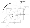
X線可動絞りは、被検体に照射するX線の照射面積(X線照射領域)を制限する。X線可動絞りをX線源側から見た概念図を、図2に示す。X線可動絞りは、同図の如く、上下左右、かつ、回転方向に移動可能な、例えば鉛などのX線吸収係数の高い物質で作られた独立した4枚の羽根を備え、これら羽根により被検体へのX線照射領域を制限する。例えば、点線で囲まれた円形内が、X線源からのX線が照射する領域だとすれば、このうち羽根の部分はX線が透過せず、結果、a、b、c、d点で囲まれる四角形の領域のみのX線が透過し、被検体に照射されることになる。 The X-ray movable diaphragm restricts the irradiation area (X-ray irradiation region) of X-rays irradiated to the subject. A conceptual view of the X-ray movable diaphragm viewed from the X-ray source side is shown in FIG. As shown in the figure, the X-ray movable diaphragm is equipped with four independent blades made of a material with a high X-ray absorption coefficient, such as lead, which can move in the vertical and horizontal directions and in the rotational direction. Limit the X-ray irradiation area to the subject. For example, if the inside of the circle surrounded by the dotted line is an area irradiated with X-rays from the X-ray source, the blade part does not transmit X-rays, resulting in points a, b, c, and d. X-rays of only the rectangular area surrounded by the permeation are transmitted, and the subject is irradiated.
ここで、この羽根の枚数は必ずしも4枚である必要ではなく、例えば、図3の如く8枚構成とすることも可能であり、更には、各羽根が同一のX線吸収係数である必要はなく、同図において斜めに図示された羽根(斜羽根)を他の羽根と比較して低いX線吸収係数のものとすることもある。なお、一般にX線吸収係数が高い鉛で作成された羽根は鉛羽根と、鉛よりも低いX線吸収で作成された羽根はフィルタと呼ばれるが、本明細では何れも羽根と表現し、羽根の構成は図2に示した4枚構成とする。 Here, the number of the blades is not necessarily four, and for example, it is possible to adopt a configuration of eight blades as shown in FIG. 3, and furthermore, it is necessary that each blade has the same X-ray absorption coefficient. Instead, the blades (oblique blades) shown obliquely in the figure may have a low X-ray absorption coefficient compared to other blades. In general, blades made of lead having a high X-ray absorption coefficient are called lead blades, and blades made of X-ray absorption lower than lead are called filters. In this specification, all blades are expressed as blades. The configuration is the four-sheet configuration shown in FIG.
X線平面検出器には種々の方式がある。例えば、被検体を透過したX線を光に変換するシンチレータと、このシンチレータから出力される光を電荷に変換するフォトダイオードとから構成され、一般に、間接型X線平面検出器と呼ばれるものなどがあり、薄型、軽量を特徴としている。 There are various types of X-ray flat panel detectors. For example, it consists of a scintillator that converts X-rays that have passed through the subject into light, and a photodiode that converts light output from the scintillator into electric charge, generally called an indirect X-ray flat panel detector, etc. Yes, it is thin and lightweight.
X線可動絞り範囲設定手段は、例えば、マトリクススイッチと呼ばれるもので構成される。マトリクススイッチとは、図4の如く、碁盤の目のようにスイッチが平面的に多数並べられたものであり、操作者に触られた場所の、X軸とY軸で表される2次元の位置情報を得ることが可能なものである。スイッチの構造には、操作者がスイッチを触ることによる光学的な変化や、静電容量の変化を検出する方式や、操作者が触ることにより隙間を持つ2層構造から成る薄い電極が短絡し、その位置を検出する方式など、多用なものがある。 The X-ray movable aperture range setting means is constituted by what is called a matrix switch, for example. A matrix switch is a two-dimensional representation of X-axis and Y-axis at the place touched by the operator, as shown in Fig. 4, where a number of switches are arranged in a plane like a grid. It is possible to obtain position information. The switch structure is short-circuited by a thin electrode consisting of a two-layer structure with a gap when the operator touches the switch to detect optical changes and capacitance changes. There are various methods such as a method of detecting the position.
なお、操作者が触った位置を検出する方式には、前記マトリクススイッチ以外にも、抵抗膜方式、表面弾性波方式など多種多用にあり、これらもX線可動絞り範囲設定手段に使用可能であることは無論である。 In addition to the matrix switch, there are a variety of methods for detecting the position touched by the operator, such as a resistive film method and a surface acoustic wave method, and these can also be used for the X-ray movable aperture range setting means. Of course.
図1に示す本発明の実施例1のX線画像診断装置の動作について説明を行なう。撮影に先立って、操作者はX線平面検出器を、被検体の撮影を行ないたい部位(関心領域)の近傍に配置する。 The operation of the X-ray image diagnostic apparatus according to the first embodiment of the present invention shown in FIG. 1 will be described. Prior to imaging, the operator places an X-ray flat panel detector in the vicinity of a region (region of interest) where the subject is desired to be imaged.
このX線平面検出器は、図示しない支持装置により支えられ、自由自在にその位置を設定できるものとする。また、X線平面検出器が、更に薄型、軽量となれば、被検体自身がX線平面検出器を支えることが可能となるであろう。 This X-ray flat panel detector is supported by a support device (not shown), and its position can be freely set. If the X-ray flat panel detector becomes thinner and lighter, the subject itself will be able to support the X-ray flat panel detector.
図中のX線源とX線可動絞りは、常に図示しない支持装置に支えられ、自由自在にその位置が設定できるものとし、X線平面検出器が関心領域近傍に配置された際には、図示しない機構による自動追従、もしくは、操作者による手動動作により、X線平面検出器と対向かつX線平面検出器の視野中心とX線源とX線可動絞りの中心点が一致するよう位置するものとする。 The X-ray source and X-ray movable diaphragm in the figure are always supported by a support device (not shown), and its position can be freely set.When the X-ray flat panel detector is placed near the region of interest, Positioned so that the center of the field of view of the X-ray flat panel detector coincides with the center point of the X-ray source and the X-ray movable diaphragm by automatic tracking by a mechanism (not shown) or manual operation by the operator. Shall.
なお、X線源とX線可動絞りとの距離d1は装置構造により決定される定数であり、既知である。また、X線源とX線平面検出器との距離d2は、前述の自動追従によりX線源が移動する場合には、距離d2は図示しない操作入力手段により予め設定された値になるものとし、既知である。操作者による手動動作によりX線源を移動する場合には、距離d2は操作者が任意に動かした距離となるが、図示しない距離測定機構により計測され、既知となるものとする。つまり、何れの場合においても、距離d1、d2は既知な値である。 Note that the distance d1 between the X-ray source and the X-ray movable diaphragm is a constant determined by the apparatus structure and is known. Also, the distance d2 between the X-ray source and the X-ray flat panel detector is assumed to be a value set in advance by an operation input means (not shown) when the X-ray source is moved by the automatic tracking described above. Known. When the X-ray source is moved by a manual operation by the operator, the distance d2 is a distance arbitrarily moved by the operator, but is measured by a distance measuring mechanism (not shown) and becomes known. That is, in any case, the distances d1 and d2 are known values.
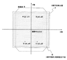
次に、操作者は、X線入射面と反対側に配置されたX線可動絞り範囲設定手段により、X線照射領域を設定する。図5に、X線平面検出器、X線可動絞り範囲設定手段、被検体を、X線入射方向と逆側から図示したものを示す。このX線可動絞り範囲設定手段は、前述のマトリクスセンサで構成され、その検出範囲はX線平面検出器の最大視野サイズと同一の大きさとしている。 Next, the operator sets the X-ray irradiation area by the X-ray movable diaphragm range setting means arranged on the side opposite to the X-ray incident surface. FIG. 5 shows an X-ray flat panel detector, an X-ray movable aperture range setting means, and a subject illustrated from the opposite side to the X-ray incident direction. This X-ray movable aperture range setting means is composed of the matrix sensor described above, and its detection range is the same as the maximum field size of the X-ray flat panel detector.
操作者は、関心領域を取り囲むように、このX線可動絞り範囲設定手段の4点を触る。同図では、A〜D点の4点が、操作者が触った4点としている。X線可動絞り範囲設定手段では、この操作者が触った4点の、X、Yの2軸で表現される位置情報を、有線もしくは無線にて制御装置に送信する。なお、本明細書では、X線平面検出器の視野中心を原点とし、大地に対して水平方向をX軸、垂直方向をY軸として表現する。 The operator touches the four points of the X-ray movable aperture range setting means so as to surround the region of interest. In the figure, the four points A to D are the four points touched by the operator. The X-ray movable aperture range setting means transmits the position information expressed by the two axes X and Y touched by the operator to the control device by wire or wirelessly. In this specification, the center of the field of view of the X-ray flat panel detector is the origin, the horizontal direction with respect to the ground is expressed as the X axis, and the vertical direction is expressed as the Y axis.
制御装置は、操作者が触った4点からX線を照射する領域を決定し、X線可動絞りの羽根の位置情報を算出する。例えば、図6の如く操作者が触った4点の座標がそれぞれA(x1,y1)、B(x2,y2)、C(x3,y3)、D(x4,y4)であり、その各点が頂点となる四角形の領域がX線照射領域になるとする。なお、ここでは関心領域範囲の設定が、X線可動絞り位置設定手段の4点を触ることにより行なわれるとしたが、必ずしもこれに限定されるものではなく、例えば、操作者が関心領域を囲むように指でなぞることで、X線照射領域を設定することも容易に実現可能であり、また、関心領域の指定が中途半端であったとしても、その軌跡から操作者が望んだであろう領域を推測し、X線照射領域を設定することも容易に実現可能である。 The control device determines a region to be irradiated with X-rays from four points touched by the operator, and calculates position information of the blades of the X-ray movable diaphragm. For example, as shown in FIG. 6, the coordinates of the four points touched by the operator are A (x1, y1), B (x2, y2), C (x3, y3), and D (x4, y4), respectively. Assume that a quadrangular region where is a vertex is an X-ray irradiation region. Here, the region of interest range is set by touching the four points of the X-ray movable aperture position setting means. However, the present invention is not necessarily limited to this. For example, the operator surrounds the region of interest. In this way, it is possible to easily set the X-ray irradiation area by tracing with a finger, and even if the area of interest is specified halfway, the operator would have desired it Estimating the area and setting the X-ray irradiation area can be easily realized.
このX線照射領域の座標と、X線可動絞り羽根の位置には、図7の如く相似の関係にあることから、操作者により指定されたX線照射領域を満足するX線可動絞り、それぞれの羽根の中心点からのシフト量は、以下の式(1)から(4)で表される。なお、それぞれの羽根の中心点からのシフト量は、図8の如く定義され、常にゼロ以上の値を取るものとする。 Since the coordinates of the X-ray irradiation area and the position of the X-ray movable diaphragm blade are similar to each other as shown in FIG. 7, the X-ray movable diaphragm satisfying the X-ray irradiation area specified by the operator, The shift amount from the center point of the blade is expressed by the following equations (1) to (4). Note that the shift amount from the center point of each blade is defined as shown in FIG. 8, and always takes a value of zero or more.
d1:WUps = d2:|y1| ・・・ (1)
d1:WDns = d2:|y3| ・・・ (2)
d1:WRts = d2:|x2| ・・・ (3)
d1:WLts = d2:|x1| ・・・ (4)
上式を整理することにより、以下の式(5)〜(8)が得られる。
d1: WUps = d2: | y1 | (1)
d1: WDns = d2: | y3 | (2)
d1: WRts = d2: | x2 | (3)
d1: WLts = d2: | x1 | (4)
By arranging the above equations, the following equations (5) to (8) are obtained.
WUps = k・|y1| ・・・ (5)
WDns = k・|y3| ・・・ (6)
WRts = k・|x2| ・・・ (7)
WLts = k・|x1| ・・・ (8)
但し、k = d1/d2 ・・・ (9)
このとき、図7における、距離d1、距離d2は、前述の如く既知な値であり、それぞれの羽根の中心点からのシフト量は算出可能となる。
WUps = k ・ | y1 | ・ ・ ・ (5)
WDns = k ・ | y3 | ・ ・ ・ (6)
WRts = k ・ | x2 | (7)
WLts = k ・ | x1 | (8)
However, k = d1 / d2 (9)
At this time, the distance d1 and the distance d2 in FIG. 7 are known values as described above, and the shift amount from the center point of each blade can be calculated.
制御装置は、前述の式(5)〜(8)及び(9)で算出した、それぞれの羽根の中心点からのシフト量を、有線もしくは無線にてX線可動絞り装置に送信する。 The control device transmits the shift amount from the center point of each blade calculated by the above formulas (5) to (8) and (9) to the X-ray movable aperture device by wire or wirelessly.
なお、ここまでX線照射領域が視野中心を中心として回転した位置に設定された場合について説明を行なっていないが、X線照射領域が視野中心を中心として回転した位置に設定されたとしても、X線可動絞りの羽根を同様の角度で回転させれば良く、容易に実現可能である。 Although the case where the X-ray irradiation region is set at a position rotated around the center of the visual field has not been described so far, even if the X-ray irradiation region is set at a position rotated around the visual field center, This can be easily realized by rotating the blades of the X-ray movable diaphragm at the same angle.
X線可動絞りでは、制御装置から受信した、中心点からのシフト量に従い、それぞれの羽根を動かし、X線照射領域を決定する。 In the X-ray movable diaphragm, each blade is moved according to the shift amount from the central point received from the control device, and the X-ray irradiation area is determined.
以上の動作により、X線可動絞り位置設定手段であるマトリクススイッチを触ることにより、容易、かつ、直感的にX線照射領域を設定することが可能となる。
なお、図1に示した本発明のX線画像診断装置は、被検体を載置する検診台を必要としない、例えば胸部撮影について説明したが、本発明はこれに限定するものではない。
With the above operation, the X-ray irradiation area can be set easily and intuitively by touching the matrix switch which is the X-ray movable aperture position setting means.
The X-ray diagnostic imaging apparatus of the present invention shown in FIG. 1 does not require an examination table on which a subject is placed, for example, chest imaging has been described, but the present invention is not limited to this.
また、本実施例においては、説明を行ないやすくするため、制御装置を図示したが、必ずしもユニットとして独立して存在する必要はなく、その機能をX線可動絞り範囲検出手段もしくはX線可動絞りにもたせることも可能である。 In the present embodiment, the control device is shown for ease of explanation, but it does not necessarily have to exist as a unit, and its function is not limited to the X-ray movable diaphragm range detecting means or the X-ray movable diaphragm. It can also be given.
上述の本実施例によれば、X線を被検体に照射するX線源と、X線の照射領域を制限する羽根を有して成るX線可動絞りと、X線源と対向配置された被検体の透過X線を検出するX線平面検出器とを備えたX線画像診断装置において、X線平面検出器のX線入射面と反対側にX線可動絞り範囲設定手段が配置され、X線可動絞り範囲設定手段及びX線可動絞りと有線もしくは無線にて通信を行い各種制御を行なう制御装置が備えられ、前記X線可動絞り範囲設定手段は少なくとも操作者に触られた場所の2次元の位置情報を得、この位置情報を元に前記X線可動絞りの羽根の位置を制御して、適切なX線照射領域を設定することを特徴とするX線画像診断装置が提供される。 According to the above-described embodiment, the X-ray source for irradiating the subject with X-rays, the X-ray movable diaphragm including the blades for limiting the X-ray irradiation area, and the X-ray source are disposed opposite to each other. In an X-ray diagnostic imaging apparatus comprising an X-ray flat panel detector for detecting transmitted X-rays of a subject, an X-ray movable diaphragm range setting means is disposed on the opposite side of the X-ray incident surface of the X-ray flat panel detector, An X-ray movable diaphragm range setting means and a control device for performing various controls by communicating with the X-ray movable diaphragm in a wired or wireless manner are provided, and the X-ray movable diaphragm range setting means is at least two places touched by an operator. Provided is an X-ray diagnostic imaging apparatus that obtains three-dimensional position information, controls the position of the blade of the X-ray movable diaphragm based on the position information, and sets an appropriate X-ray irradiation area. .
図9は、本発明のX線画像診断装置における実施例2の構成を示す模式図である。
同図において、前記実施例1と同様な機能を有する構成要素については同一符号で記し、その説明は省略する。
図9に示す本発明の実施例2のX線画像診断装置は、図1に示した実施例1のX線画像診断装置に、X線源とX線平面検出器との距離による、X線可動絞りの羽根位置の補正機能を付加したものである。ここで、このX線源とX線平面検出器との距離は一般にSID(Source Image Distance)と呼ばれ、本明細では以後この名称を使用するものとし、前記補正機能を持つユニットをSID補正機構と呼ぶ。
FIG. 9 is a schematic diagram showing a configuration of Example 2 in the X-ray image diagnostic apparatus of the present invention.
In the figure, components having functions similar to those of the first embodiment are denoted by the same reference numerals, and description thereof is omitted.
The X-ray image diagnostic apparatus according to the second embodiment of the present invention shown in FIG. 9 is different from the X-ray image diagnostic apparatus according to the first embodiment shown in FIG. 1 according to the distance between the X-ray source and the X-ray flat panel detector. A function for correcting the blade position of the movable diaphragm is added. Here, the distance between the X-ray source and the X-ray flat detector is generally called SID (Source Image Distance). In this specification, this name will be used hereinafter, and the unit having the correction function is referred to as the SID correction mechanism. Call it.
X線画像診断装置で使用されるX線は平行X線ではなく、ある微小面積を持つX線源を頂点として、円錐状に照射されたX線であり、広がりを持つ。よって、関心領域を撮影するためのX線照射領域を厳密に指定しようとするならば、操作者はこのX線の広がりを考慮してX線可動絞り範囲設定手段により領域指定を行なう必要がある。例えば図10において、グラデーションを掛けて塗りつぶした領域を関心領域とすると、操作者はX線の広がりを意識して、X線照射領域を指定する4点を、E、F、G、Hとする必要がある。 The X-rays used in the X-ray diagnostic imaging apparatus are not parallel X-rays, but X-rays that are irradiated in a conical shape with an X-ray source having a certain small area as a vertex and have a spread. Therefore, if the X-ray irradiation area for imaging the region of interest is to be specified strictly, the operator needs to specify the area by the X-ray movable aperture range setting means in consideration of the X-ray spread. . For example, in Fig. 10, if the region painted with gradation is the region of interest, the operator is aware of the spread of the X-ray, and the four points that specify the X-ray irradiation region are E, F, G, and H. There is a need.
しかし、通常の操作者が、X線の広がりを意識してE〜H点を設定することは困難であり、真の関心領域よりも広い領域をX線照射領域として指定し、被検体の無効被曝を増大させたり、もしくは、X線照射領域が真の関心領域よりも狭い領域となり、診断情報の欠損を招くことが起こりえる。 However, it is difficult for a normal operator to set points E to H in consideration of the spread of X-rays, and a region wider than the true region of interest is designated as the X-ray irradiation region, and the subject is invalidated. The exposure may increase, or the X-ray irradiation area may be narrower than the true area of interest, leading to loss of diagnostic information.
操作者がX線照射領域を指定する場合、直感的な操作が可能なのは、関心領域をX線平面検出器の真正面から平面的に捉え、奥行き方向を意識しない場合である。そのように、関心領域を設定した場合の4点を、E’、F’、G’、H’とし、前述のE〜H点と併せ、図11に示す。SID補正機構では、この操作者が直感的に指定したE’〜H’点から、X線の広がりを考慮した、適切なX線照射領域となるE〜H点を自動で算出する。 When an operator designates an X-ray irradiation region, an intuitive operation is possible when the region of interest is planarly viewed from the front of the X-ray flat detector and the depth direction is not conscious. In this way, the four points when the region of interest is set are designated as E ′, F ′, G ′, and H ′, and are shown in FIG. 11 together with the points E to H described above. The SID correction mechanism automatically calculates E to H points that are appropriate X-ray irradiation areas in consideration of the X-ray spread, from E 'to H' points that the operator intuitively specifies.
最初に、E点の座標(x5,y5)のうち、Y座標の算出方法について示す。図11から、明らかに以下の式(10)は成立する。 First, a method for calculating the Y coordinate among the coordinates (x5, y5) of the point E will be described. From FIG. 11, it is clear that the following equation (10) holds.
y5 = y9+L2 ・・・ (10)
ここで、M点とN点とP点で結ばれる3角形と、P点とQ点とR点で結ばれる3角形が相似の関係にあることから、L2は以下の式(11)で表わされる
L2 = tanθ・L1 = (y9/(d2-L1))・L1 ・・・ (11)
よって、式(11)を式(10)に代入することにより、E点のY座標は以下の式(12)で表わされる。
y5 = y9 + L2 (10)
Here, since the triangle connected by the M point, the N point, and the P point and the triangle connected by the P point, the Q point, and the R point have a similar relationship, L2 is expressed by the following equation (11). Be
L2 = tanθ ・ L1 = (y9 / (d2-L1)) ・ L1 (11)
Therefore, by substituting equation (11) into equation (10), the Y coordinate of point E is expressed by equation (12) below.
y5 = y9+(y9/(d2-L1))・L1 ・・・ (12)
E点のX座標、及び、F〜H点のX座標、Y座標も同様の考え方で算出可能であり、以下の式(13)〜(19)で表わされる。
y5 = y9 + (y9 / (d2-L1)) ・ L1 (12)
The X coordinate of point E and the X and Y coordinates of points F to H can be calculated in the same way, and are expressed by the following equations (13) to (19).
x5 = x9+(x9/(d2-L1))・L1 ・・・ (13)
y6 = y10+(y10/(d2-L1))・L1 ・・・ (14)
x6 = x10+(x10/(d2-L1))・L1 ・・・ (15)
y7 = y11+(y11/(d2-L1))・L1 ・・・ (16)
x7 = x11+(x11/(d2-L1))・L1 ・・・ (17)
y8 = y12+(y12/(d2-L1))・L1 ・・・ (18)
x8 = x12+(x12/(d2-L1))・L1 ・・・ (19)
ここで、式(12)〜(19)における、関心領域の厚さL1は、検査対象部位、被検体の個体差により異なるが、図示しない操作卓における、検査部位の指定手段、また、被検体の厚さ入力手段により、あらかじめ既知の値とする。
x5 = x9 + (x9 / (d2-L1)) ・ L1 ... (13)
y6 = y10 + (y10 / (d2-L1)) ・ L1 ... (14)
x6 = x10 + (x10 / (d2-L1)) ・ L1 ... (15)
y7 = y11 + (y11 / (d2-L1)) ・ L1 ... (16)
x7 = x11 + (x11 / (d2-L1)) ・ L1 ... (17)
y8 = y12 + (y12 / (d2-L1)) ・ L1 ... (18)
x8 = x12 + (x12 / (d2-L1)) ・ L1 ... (19)
Here, in the formulas (12) to (19), the thickness L1 of the region of interest varies depending on the region to be examined and the individual difference of the subject. The thickness is input to a known value in advance.
また、実施例1と同様にX線源とX線可動絞りは、X線平面検出器の移動に対する自動追従、もしくは、操作者による手動動作により、X線照射領域を指定する前にはその位置が既に決定されているものとし、式(12)〜(19)におけるSID、すなわちd2は既知の値とする。これにより、E'〜H'点が指定されれば、E〜H点は算出可能となる。 Similarly to the first embodiment, the X-ray source and the X-ray movable diaphragm are positioned before the X-ray irradiation area is designated by automatic tracking of the movement of the X-ray flat panel detector or by manual operation by the operator. Is already determined, and SID in equations (12) to (19), that is, d2 is a known value. Thereby, if the points E ′ to H ′ are designated, the points E to H can be calculated.
SID補正機構では、式(12)〜(19)に従って補正演算を行なった後、その位置情報を、有線もしくは無線にて制御装置に送信する。以降の処理は、実施例1と同様である。 In the SID correction mechanism, after performing the correction calculation according to the equations (12) to (19), the position information is transmitted to the control device by wire or wirelessly. The subsequent processing is the same as in the first embodiment.
なお、本実施例においては、説明を行ないやすくするため、制御装置及びSID補正機構を図示したが、必ずしもユニットとして独立して存在する必要はなく、その機能をX線可動絞り範囲検出手段もしくはX線可動絞りにもたせることも可能である。 In the present embodiment, the control device and the SID correction mechanism are shown for ease of explanation, but they do not necessarily exist independently as a unit, and their functions are not limited to the X-ray movable aperture range detecting means or X It is also possible to put it on a line movable diaphragm.
上述の本実施例によれば、X線の広がりと、X線画像診断装置及び被検体の幾何学的配置とに基づいて、前記X線可動絞りの羽根の位置を補正する補正手段を備えたことを特徴とするX線画像診断装置が提供される。 According to the above-described embodiment, the correction means for correcting the position of the blade of the X-ray movable diaphragm is provided based on the spread of the X-ray and the geometric arrangement of the X-ray diagnostic imaging apparatus and the subject. An X-ray diagnostic imaging apparatus is provided.
図12は、本発明のX線画像診断装置における実施例3の構成を示す模式図である。同図において、前記第1もしくは第2の実施例と同様な機能を有する構成要素については同一符号で記し、その説明は省略する。図12に示す本発明の実施例3のX線画像診断装置は、第1もしくは第2の実施例のX線画像診断装置において、そのX線可動絞り範囲設定手段に、表示機能を備え、かつ、マトリクスセンサと同様に操作者が触る場所の位置情報を得ることが可能なものを使用している。なお、図12においては、実施例2におけるSID補正機構は図示していない。
FIG. 12 is a schematic diagram showing a configuration of Example 3 in the X-ray image diagnostic apparatus of the present invention. In the figure, components having the same functions as those in the first or second embodiment are denoted by the same reference numerals, and the description thereof is omitted. The X-ray diagnostic imaging apparatus of
実施例1もしくは実施例2においては、X線可動絞り範囲設定手段に表示機能を有さないため、指定したX線照射領域を操作者が認識する手段を持たなかったが、本実施例ではその点を改良できる。 In Example 1 or Example 2, since the X-ray movable aperture range setting means does not have a display function, the operator does not have means for recognizing the designated X-ray irradiation area. The point can be improved.
図12の如く、操作者によりX線照射領域が指定されたとする。X線可動絞り範囲指定手段では、そのS点とT点、T点とU点、U点とV点、V点とS点、それぞれを結ぶ4つの線分を描画し、X線照射領域を操作者に判るよう表示する。更には、線分で囲まれる領域を色づけすることも有効である。 Assume that an X-ray irradiation area is designated by the operator as shown in FIG. The X-ray movable aperture range designation means draws four line segments connecting the S and T points, the T and U points, the U and V points, and the V and S points. Display to the operator. It is also effective to color the area surrounded by the line segment.
なお、X線可動絞り範囲指定手段に表示機能を付加することにより、撮影した画像の簡易表示機能や、SIDや各種撮影条件の設定機構を付加することが容易に可能となることは無論である。 It goes without saying that by adding a display function to the X-ray movable aperture range specifying means, it is possible to easily add a simple display function for captured images and a setting mechanism for SID and various imaging conditions. .
上述の本実施例によれば、前記位置情報を表示する表示手段を備えたことを特徴とするX線画像診断装置が提供される。 According to the above-described embodiment, there is provided an X-ray image diagnostic apparatus comprising a display unit that displays the position information.
1 X線源、2 X線可動絞り、3 羽根、4 制御装置、5 被検体、6 X線可動絞り範囲設定手段、7 X線平面検出器、8 スイッチ、9 SID補正機能、10 表示機能を有した、X線可動絞り範囲設定手段 1 X-ray source, 2 X-ray movable aperture, 3 blades, 4 control device, 5 subject, 6 X-ray movable aperture range setting means, 7 X-ray flat panel detector, 8 switch, 9 SID correction function, 10 display function X-ray movable aperture range setting means
Claims (2)
前記X線平面検出器のX線入射面とは異なる側に前記X線可動絞りの羽根の移動範囲を設定する
X線可動絞り範囲設定手段と、該X線可動絞り範囲設定手段により設定された情報に基づいて前記X線可動絞りの羽根を移動制御する制御部と、を有し、
前記制御部は、操作者により前記X線可動絞り範囲設定手段を用いて設定されたX線照射領域が、前記X線源と前記X線平面検出器の間に配置された前記被検体のおける前記X線源側であるX線照射面の体表での領域となるよう、前記設定されたX線照射領域と、前記X線源、X線可動絞り、及びX線平面検出器のそれぞれの間隔の値と、前記被検体の体厚の値と、に基づいて前記X線可動絞りの羽根を移動制御することを特徴とするX線画像診断装置。 An X-ray source that irradiates a subject with X-rays, an X-ray movable diaphragm that has blades that limit an X-ray irradiation region irradiated from the X-ray source, and the X-ray source disposed opposite to the X-ray movable diaphragm In an X-ray diagnostic imaging apparatus comprising: an X-ray flat panel detector that detects transmitted X-rays of a subject;
X-ray movable diaphragm range setting means for setting the movement range of the blades of the X-ray movable diaphragm on the side different from the X-ray incident surface of the X-ray flat panel detector, and the X-ray movable diaphragm range setting means. A control unit that controls movement of the blades of the X-ray movable diaphragm based on the information,
The control unit places an X-ray irradiation region set by an operator using the X-ray movable diaphragm range setting unit in the subject arranged between the X-ray source and the X-ray flat panel detector. Each of the set X-ray irradiation area, the X-ray source, the X-ray movable diaphragm, and the X-ray flat panel detector so as to be an area on the body surface of the X-ray irradiation surface on the X-ray source side . An X-ray diagnostic imaging apparatus, wherein movement of the blades of the X-ray movable diaphragm is controlled based on an interval value and a body thickness value of the subject.
Priority Applications (1)
| Application Number | Priority Date | Filing Date | Title |
|---|---|---|---|
| JP2007314443A JP5435860B2 (en) | 2007-12-05 | 2007-12-05 | X-ray diagnostic imaging equipment |
Applications Claiming Priority (1)
| Application Number | Priority Date | Filing Date | Title |
|---|---|---|---|
| JP2007314443A JP5435860B2 (en) | 2007-12-05 | 2007-12-05 | X-ray diagnostic imaging equipment |
Publications (3)
| Publication Number | Publication Date |
|---|---|
| JP2009136425A JP2009136425A (en) | 2009-06-25 |
| JP2009136425A5 JP2009136425A5 (en) | 2011-01-27 |
| JP5435860B2 true JP5435860B2 (en) | 2014-03-05 |
Family
ID=40867721
Family Applications (1)
| Application Number | Title | Priority Date | Filing Date |
|---|---|---|---|
| JP2007314443A Expired - Fee Related JP5435860B2 (en) | 2007-12-05 | 2007-12-05 | X-ray diagnostic imaging equipment |
Country Status (1)
| Country | Link |
|---|---|
| JP (1) | JP5435860B2 (en) |
Families Citing this family (5)
| Publication number | Priority date | Publication date | Assignee | Title |
|---|---|---|---|---|
| KR101373006B1 (en) * | 2011-12-27 | 2014-03-13 | 삼성전자주식회사 | The method and apparatus for adjusting a range of x-ray emission |
| US20140226793A1 (en) * | 2013-02-13 | 2014-08-14 | Dental Imaging Technologies Corporation | Automatic field-of-view size calculation constraint |
| EP2767236A1 (en) * | 2013-02-15 | 2014-08-20 | Koninklijke Philips N.V. | X-ray collimator size and position adjustment based on pre-shot |
| CN104434148B (en) * | 2013-09-12 | 2019-01-08 | 上海联影医疗科技有限公司 | A kind of control method of X-ray shooting system |
| US9192343B2 (en) | 2013-11-19 | 2015-11-24 | Scanflex Healthcare AB | Fluoroscopy system |
Family Cites Families (11)
| Publication number | Priority date | Publication date | Assignee | Title |
|---|---|---|---|---|
| JPH05161635A (en) * | 1991-12-13 | 1993-06-29 | Toshiba Corp | X-ray diagnostic sheet system |
| JP3456718B2 (en) * | 1993-01-27 | 2003-10-14 | 株式会社東芝 | X-ray equipment |
| JPH10192427A (en) * | 1997-01-07 | 1998-07-28 | Toshiba Corp | Radiotherapy planning device |
| JPH10295679A (en) * | 1997-04-23 | 1998-11-10 | Fuji Photo Film Co Ltd | Recognition method and device for irradiation area of radiation image |
| JP3329257B2 (en) * | 1998-01-30 | 2002-09-30 | 株式会社島津製作所 | Radiation treatment planning device |
| JP2001340332A (en) * | 2000-06-05 | 2001-12-11 | Hitachi Medical Corp | Radiodiagnosing device |
| JP2003116847A (en) * | 2001-10-12 | 2003-04-22 | Hitachi Medical Corp | X-ray system |
| JP4503385B2 (en) * | 2004-07-28 | 2010-07-14 | 株式会社日立メディコ | X-ray equipment |
| WO2006038165A1 (en) * | 2004-10-05 | 2006-04-13 | Philips Intellectual Property & Standards Gmbh | Method and system for the planning of imaging parameters |
| JP2007143982A (en) * | 2005-11-29 | 2007-06-14 | Hitachi Medical Corp | Radiographic apparatus |
| JP4817365B2 (en) * | 2006-03-03 | 2011-11-16 | 株式会社日立メディコ | X-ray diagnostic equipment |
-
2007
- 2007-12-05 JP JP2007314443A patent/JP5435860B2/en not_active Expired - Fee Related
Also Published As
| Publication number | Publication date |
|---|---|
| JP2009136425A (en) | 2009-06-25 |
Similar Documents
| Publication | Publication Date | Title |
|---|---|---|
| US11229416B2 (en) | X-ray imaging apparatus and method for controlling the same | |
| EP2774541B1 (en) | Mobile X-ray imaging apparatus and control method for the same | |
| KR101812019B1 (en) | X-ray device and x-ray radiation area control method using the same | |
| US9848840B2 (en) | X-ray diagnostic apparatus comprising an X-ray filter movable along an imaging axis of X-rays | |
| JP6645965B2 (en) | X-ray reduction system | |
| JP5435860B2 (en) | X-ray diagnostic imaging equipment | |
| JP6109650B2 (en) | X-ray diagnostic apparatus, exposure management apparatus, scattered radiation dose distribution forming method, and scattered radiation dose distribution forming program | |
| KR102483330B1 (en) | Medical image apparatus and operation method of the same | |
| US20150310602A1 (en) | X-ray imaging apparatus and image processing method thereof | |
| JP2013220218A (en) | Radiographic imaging apparatus, control method therefor, and program | |
| US20170172535A1 (en) | Radiographic imaging apparatus and method for controlling the same | |
| CN107405125B (en) | X-ray fluoroscopic photographing apparatus | |
| US9420985B2 (en) | X-ray diagnostic apparatus and dose distribution generation method | |
| US8905636B2 (en) | X-ray diagnostic apparatus | |
| US8475043B2 (en) | Radiation imaging apparatus and processing method therefor | |
| JP5588775B2 (en) | X-ray diagnostic imaging equipment | |
| JP7325943B2 (en) | MEDICAL IMAGE DIAGNOSTIC SYSTEM AND PARAMETER SELECTION METHOD | |
| JP7175639B2 (en) | X-ray imaging device and medical image processing device | |
| JP2009291504A (en) | X-ray diagnostic imaging apparatus | |
| JP2014033850A (en) | Medical image capturing apparatus and medical image capturing method | |
| JP7278053B2 (en) | X-ray CT system | |
| JP2016168293A (en) | X-ray image diagnostic apparatus and image transfer method | |
| JP2011062433A (en) | X-ray diagnostic apparatus | |
| JP2006255216A (en) | X-ray diagnostic imaging apparatus | |
| US11957495B2 (en) | X-ray imaging apparatus and method for controlling the same |
Legal Events
| Date | Code | Title | Description |
|---|---|---|---|
| A521 | Request for written amendment filed |
Free format text: JAPANESE INTERMEDIATE CODE: A523 Effective date: 20101203 |
|
| A621 | Written request for application examination |
Free format text: JAPANESE INTERMEDIATE CODE: A621 Effective date: 20101203 |
|
| A977 | Report on retrieval |
Free format text: JAPANESE INTERMEDIATE CODE: A971007 Effective date: 20120425 |
|
| A131 | Notification of reasons for refusal |
Free format text: JAPANESE INTERMEDIATE CODE: A131 Effective date: 20120507 |
|
| A521 | Request for written amendment filed |
Free format text: JAPANESE INTERMEDIATE CODE: A523 Effective date: 20120705 |
|
| A131 | Notification of reasons for refusal |
Free format text: JAPANESE INTERMEDIATE CODE: A131 Effective date: 20130204 |
|
| A521 | Request for written amendment filed |
Free format text: JAPANESE INTERMEDIATE CODE: A523 Effective date: 20130403 |
|
| TRDD | Decision of grant or rejection written | ||
| A01 | Written decision to grant a patent or to grant a registration (utility model) |
Free format text: JAPANESE INTERMEDIATE CODE: A01 Effective date: 20131118 |
|
| A61 | First payment of annual fees (during grant procedure) |
Free format text: JAPANESE INTERMEDIATE CODE: A61 Effective date: 20131210 |
|
| R150 | Certificate of patent or registration of utility model |
Ref document number: 5435860 Country of ref document: JP Free format text: JAPANESE INTERMEDIATE CODE: R150 Free format text: JAPANESE INTERMEDIATE CODE: R150 |
|
| S111 | Request for change of ownership or part of ownership |
Free format text: JAPANESE INTERMEDIATE CODE: R313111 |
|
| S533 | Written request for registration of change of name |
Free format text: JAPANESE INTERMEDIATE CODE: R313533 |
|
| R350 | Written notification of registration of transfer |
Free format text: JAPANESE INTERMEDIATE CODE: R350 |
|
| LAPS | Cancellation because of no payment of annual fees |