JP5434948B2 - Manufacturing method of cover glass plate - Google Patents
Manufacturing method of cover glass plate Download PDFInfo
- Publication number
- JP5434948B2 JP5434948B2 JP2011077440A JP2011077440A JP5434948B2 JP 5434948 B2 JP5434948 B2 JP 5434948B2 JP 2011077440 A JP2011077440 A JP 2011077440A JP 2011077440 A JP2011077440 A JP 2011077440A JP 5434948 B2 JP5434948 B2 JP 5434948B2
- Authority
- JP
- Japan
- Prior art keywords
- glass plate
- cover glass
- manufacturing
- upper mold
- recess
- Prior art date
- Legal status (The legal status is an assumption and is not a legal conclusion. Google has not performed a legal analysis and makes no representation as to the accuracy of the status listed.)
- Expired - Fee Related
Links
Images
Classifications
-
- C—CHEMISTRY; METALLURGY
- C03—GLASS; MINERAL OR SLAG WOOL
- C03B—MANUFACTURE, SHAPING, OR SUPPLEMENTARY PROCESSES
- C03B11/00—Pressing molten glass or performed glass reheated to equivalent low viscosity without blowing
- C03B11/06—Construction of plunger or mould
- C03B11/08—Construction of plunger or mould for making solid articles, e.g. lenses
- C03B11/088—Flat discs
Description
本発明はカバーガラス板の製造方法に関するものであり、例えばスマートフォンの画像表示面に設けられるカバーガラス板の製造方法に関するものである。 The present invention relates to a method for manufacturing a cover glass plate, for example, a method for manufacturing a cover glass plate provided on an image display surface of a smartphone.
画像表示機能を有するデジタル機器(例えば、携帯電話,スマートフォン,モバイルコンピュータ等)には、その画像表示面を保護するためのカバーガラス板が通常設けられる。そのカバーガラス板は、平板状に成形された大面積の板ガラスを所定のサイズに切断することにより製造される。このため、板ガラスの切断後にはその外形枠加工が必要になる。つまり、矩形の板ガラスの4つの角や四辺を構成する側面の境界を滑らかに面取りしたり丸めたりする外形枠加工が必要になる(例えば、特許文献1参照。)。また、カバーガラス板の表面を平面から曲面へと仕様変更するニーズが近年高まってきているが、平板状に成形された板ガラスの表面を曲面化するには後加工が必要になる。 A digital device having an image display function (for example, a mobile phone, a smartphone, a mobile computer, etc.) is usually provided with a cover glass plate for protecting the image display surface. The cover glass plate is manufactured by cutting a large area plate glass formed into a flat plate shape into a predetermined size. For this reason, the outer frame processing is required after cutting the plate glass. That is, it is necessary to perform outline frame processing that smoothly chamfers or rounds the boundaries of the side surfaces that form four corners and four sides of a rectangular plate glass (see, for example, Patent Document 1). Moreover, although the need to change the specification of the surface of the cover glass plate from a flat surface to a curved surface has been increasing in recent years, post-processing is required to make the surface of the plate glass formed into a flat plate into a curved surface.
しかし、カバーガラス板の外形枠加工やカバーガラス板表面の後加工を行おうとすると、製造工程の増大や複雑化が生じてしまい、その結果としてコストアップを招くことになる。 However, if the outer frame processing of the cover glass plate or the post-processing of the surface of the cover glass plate is performed, the manufacturing process is increased and complicated, resulting in an increase in cost.
本発明はこのような状況に鑑みてなされたものであって、その目的は、カバーガラス板の外形枠加工やカバーガラス板表面の後加工を行わずに、任意の外枠形状及び表面形状を有するカバーガラス板を容易に製造することを可能とする、カバーガラス板の製造方法を提供することにある。 The present invention has been made in view of such a situation, and the object thereof is to form an arbitrary outer frame shape and surface shape without performing the outer frame processing of the cover glass plate or the post-processing of the cover glass plate surface. It is providing the manufacturing method of a cover glass plate which makes it possible to manufacture the cover glass plate which has easily.
上記目的を達成するために、第1の発明のカバーガラス板の製造方法は、下金型の平面部に一定量の溶融ガラスを滴下する滴下工程と、前記平面部上の溶融ガラスを上金型でプレスすることにより、前記溶融ガラスを上金型の成形用の凹部に充填し、更に前記凹部から上金型と下金型との間にはみ出させて、そのはみ出し部分を有する予備成形体を形成するプレス工程と、平面研削又は平面研磨により前記はみ出し部分を前記予備成形体からすべて取り除く加工工程と、を有することを特徴とする。 In order to achieve the above object, a method for producing a cover glass plate according to a first aspect of the present invention includes a dropping step of dripping a certain amount of molten glass onto a flat part of a lower mold, and an upper metal for the molten glass on the flat part. By pressing with a mold, the molten glass is filled in the concave part for molding of the upper mold, and further protrudes from the concave part between the upper mold and the lower mold, and has a protruding part. And a processing step of removing all the protruding portions from the preform by surface grinding or surface polishing.
第2の発明のカバーガラス板の製造方法は、上記第1の発明において、前記加工工程におけるはみ出し部分の平面研削又は平面研磨を、前記プレス工程における前記平面部との接触面に対して行うことを特徴とする。 The manufacturing method of the cover glass plate of 2nd invention WHEREIN: In said 1st invention, surface grinding or surface polishing of the protrusion part in the said process process is performed with respect to the contact surface with the said plane part in the said press process. It is characterized by.
第3の発明のカバーガラス板の製造方法は、上記第1又は第2の発明において、カバーガラス板の上面及び側面を前記凹部で形成し、カバーガラス板の下面を前記平面研削又は平面研磨により形成することを特徴とする。 According to a third aspect of the present invention, there is provided a cover glass plate manufacturing method according to the first or second aspect, wherein the upper surface and the side surface of the cover glass plate are formed by the recesses, and the lower surface of the cover glass plate is formed by the surface grinding or the surface polishing. It is characterized by forming.
第4の発明のカバーガラス板の製造方法は、上記第1〜第3のいずれか1つの発明において、前記凹部の一部又は全体の面形状が曲面であることを特徴とする。 According to a fourth aspect of the present invention, there is provided a cover glass plate manufacturing method according to any one of the first to third aspects, wherein a part or the entire surface shape of the recess is a curved surface.
第5の発明のカバーガラス板の製造方法は、上記第1〜第4のいずれか1つの発明において、前記プレス工程において前記はみ出し部分と接触する前記上金型の表面が、前記凹部の表面よりも粗くなっていることを特徴とする。 According to a fifth aspect of the present invention, there is provided a cover glass plate manufacturing method according to any one of the first to fourth aspects, wherein the surface of the upper mold contacting the protruding portion in the pressing step is less than the surface of the recess. Is also roughened.
カバーガラス板の外枠形状は上金型の凹部によって決まるため、加工工程における平面研削又は平面研磨により、はみ出し部分を予備成形体からすべて取り除くと、カバーガラス板の外形枠加工を行う必要がなくなる。また、カバーガラス板の表面形状も上金型の凹部によって決まるため、カバーガラス板表面の後加工を行う必要がない。したがって、第1の発明によれば、カバーガラス板の外形枠加工やカバーガラス板表面の後加工を行わずに、任意の外枠形状及び表面形状を有するカバーガラス板を容易に製造することが可能である。 Since the outer frame shape of the cover glass plate is determined by the concave portion of the upper mold, it is not necessary to process the outer frame of the cover glass plate if all the protruding portions are removed from the preform by surface grinding or surface polishing in the processing step. . Further, since the surface shape of the cover glass plate is determined by the concave portion of the upper mold, it is not necessary to perform post-processing on the surface of the cover glass plate. Therefore, according to the first invention, it is possible to easily manufacture a cover glass plate having an arbitrary outer frame shape and surface shape without performing the outer frame processing of the cover glass plate or the post-processing of the cover glass plate surface. Is possible.
下金型の平面部と上金型の成形用の凹部との位置関係は高い精度で調整可能であるため、加工工程におけるはみ出し部分の平面研削又は平面研磨を、プレス工程において下金型の平面部と接触していた面に対して行うと、加工工程における平面研削又は平面研磨を高精度に行うことが可能である。したがって、第2の発明によれば、はみ出し部分のみを予備成形体からすべて取り除くことが容易に可能である。 Since the positional relationship between the flat part of the lower mold and the concave part for molding of the upper mold can be adjusted with high accuracy, surface grinding or surface polishing of the protruding part in the machining process is performed in the pressing process. If it is performed on the surface that has been in contact with the part, surface grinding or surface polishing in the processing step can be performed with high accuracy. Therefore, according to the second invention, it is possible to easily remove only the protruding portion from the preform.
予備成形体からはみ出し部分をすべて取り除くと、上金型の成形用の凹部に充填された溶融ガラスのみから成る部分が残り、それが完成品としてのカバーガラス板となる。平面研削又は平面研磨によりカバーガラス板の下面を形成すると、他の面は上金型の凹部で形成されるため、凹部の高い精度をカバーガラス板の上面及び側面の面精度に反映させることができる。したがって、第3の発明によれば、カバーガラス板における下面以外の面の精度を制御するとともに向上させることが可能である。そして、この構成は制御の難しい粘性の高いガラスの成形においてとりわけ有効である。 When all the protruding parts are removed from the preform, a part consisting only of molten glass filled in the concave part for molding of the upper mold remains, which becomes a cover glass plate as a finished product. When the lower surface of the cover glass plate is formed by surface grinding or surface polishing, the other surface is formed by the concave portion of the upper mold, so that the high accuracy of the concave portion can be reflected in the surface accuracy of the upper surface and the side surface of the cover glass plate. it can. Therefore, according to the third invention, it is possible to control and improve the accuracy of the surface other than the lower surface of the cover glass plate. This configuration is particularly effective in forming highly viscous glass that is difficult to control.
溶融ガラスが充填される凹部の形状により、カバーガラス板の上面の形状が決まる。したがって、凹部の一部又は全体の面形状を曲面にすれば、カバーガラス板の上面の一部又は全体の面形状を曲面にすることができる。したがって、第4の発明によれば、カバーガラス板の表面を平面から曲面へと仕様変更するニーズに簡単に対応することができる。 The shape of the upper surface of the cover glass plate is determined by the shape of the recess filled with the molten glass. Therefore, if a part or the whole surface shape of the concave portion is a curved surface, a part or the whole surface shape of the upper surface of the cover glass plate can be a curved surface. Therefore, according to the fourth aspect of the invention, it is possible to easily meet the need for changing the specification of the surface of the cover glass plate from a flat surface to a curved surface.
プレス工程においてはみ出し部分と接触する上金型の表面を、凹部の表面よりも粗くすると、成形完了後のガラス収縮作用により粗面部の剥離が発生し、予備成形体の接触面の離型が促進される。したがって、第5の発明によれば、予備成形体の離型性を向上させることができる。 If the surface of the upper mold that comes into contact with the protruding part in the pressing process is made rougher than the surface of the concave part, the rough surface part peels off due to the glass shrinking action after the molding is completed, and the release of the contact surface of the preform is accelerated. Is done. Therefore, according to 5th invention, the mold release property of a preforming body can be improved.
以下、本発明を実施したカバーガラス板の製造方法を、図面を参照しつつ説明する。なお、具体例等の相互で同一の部分や相当する部分には同一の符号を付して重複説明を適宜省略する。 Hereinafter, the manufacturing method of the cover glass plate which implemented this invention is demonstrated, referring drawings. In addition, the same code | symbol is mutually attached | subjected to a mutually the same part of specific examples etc., and duplication description is abbreviate | omitted suitably.
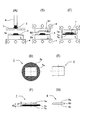
図1に、カバーガラス板の製造方法の一実施の形態を示す。この製造方法は、図1(A)〜(C)の断面図に示す成形工程と、図1(D)及び(E)の平面図並びに図1(F)及び(G)の断面図に示す加工工程と、を有している。滴下工程(A),移動工程(B)及びプレス工程(C)を含む成形工程では、ダイレクトプレス法によって予備成形体7が形成され、また、加工工程(D)〜(G)では、完成品としてのカバーガラス板8が形成される。このカバーガラス板8は、例えば、画像表示機能を有するデジタル機器(例えば、携帯電話,スマートフォン,モバイルコンピュータ等)の画像表示面を覆うために用いられる。 In FIG. 1, one Embodiment of the manufacturing method of a cover glass plate is shown. This manufacturing method is shown in the molding step shown in the cross-sectional views of FIGS. 1A to 1C, the plan view of FIGS. 1D and 1E, and the cross-sectional views of FIGS. 1F and 1G. And a processing step. In the molding step including the dropping step (A), the moving step (B) and the pressing step (C), the preform 7 is formed by the direct pressing method, and in the processing steps (D) to (G), the finished product is formed. A cover glass plate 8 is formed. The cover glass plate 8 is used, for example, to cover an image display surface of a digital device (for example, a mobile phone, a smartphone, a mobile computer, etc.) having an image display function.
まず、滴下工程(A)で下金型1の平面部1aに一定量の溶融ガラス3を滴下する。つまり、溶融炉で溶かして得られた溶融ガラス3を、白金ノズル6から流し出してブレード5で切断することにより、一定量の溶融ガラス3を下金型1の平面部1a上に滴下する。溶融ガラス3が下金型1で急冷されないようにするため、下金型1はヒータ4で加熱されている。したがって、平面部1a上の溶融ガラス3は所定の粘度が保たれた状態に保持・制御される。
First, a fixed amount of
次の移動工程(B)では、下金型1を上金型2の下方所定位置に移動させる。上金型2も下金型1と同様、溶融ガラス3が上金型2で急冷されないようにするため、ヒータ4で加熱されている。したがって、平面部1a上の溶融ガラス3は上金型2に接触しても所定の粘度が保たれた状態に保持・制御される。
In the next moving step (B), the
移動工程(B)で下金型1を所定時間待機させた後、プレス工程(C)に移行する。プレス工程(C)では、上金型2を下降させ、下金型1の平面部1a上の溶融ガラス3を上金型2でプレスすることにより、溶融ガラス3を上金型2の成形用の凹部2aに充填し、更に凹部2aから上金型2と下金型1との間にはみ出させて、そのはみ出し部分7bを有する予備成形体7を形成する。このように、はみ出させて成形することにより、上金型2の外部表面S2(図1(B))の最外周まで成形面を予備成形体7に転写させることができる。
After waiting the
プレス工程(C)で得られた予備成形体7を離型して取り出したら、加工工程(D)〜(G)に移行する。予備成形体7は、図1(D),(F)に示すように、成形体本体7aとはみ出し部分7b(斜線部分)から成っている。加工工程で、平面研削,平面研磨のうちの少なくとも一方を行うことにより、不要部分であるはみ出し部分7bを予備成形体7からすべて取り除くと(つまり、成形体本体7aの外枠周面に至るまで取り除く。)、成形体本体7aのみが残る。つまり、図1(E),(G)に示すように、完成品としてのカバーガラス板8が形成される。
Once the preform 7 obtained in the pressing step (C) is released and taken out, the process proceeds to the processing steps (D) to (G). As shown in FIGS. 1D and 1F, the preformed body 7 includes a molded body
はみ出し部分7bに対する平面研削・平面研磨は、平面部1aとの接触面7sに対して行われ、その際、複数個の予備成形体7をまとめて研磨パッドで粗く平面研削した後、更に細かく平面研磨していくことにより行われる。平面研削から平面研磨への切り替えは、平面部1aとの接触面7sに対して用いる研磨液を変えることにより容易に行うことができる。なお、カバーガラス板8の下面8cを鏡面にする必要が無い場合には、下面8cに皮膜を形成することにより所望の平滑度を得るようにしてもよい。
Surface grinding and surface polishing for the protruding
カバーガラス板8の外枠形状は上金型2の凹部2aによって決まるため、加工工程における平面研削又は平面研磨により、はみ出し部分7bを予備成形体7からすべて取り除くと、カバーガラス板8の外形枠加工(例えば、画像表示面の矩形に対応した4面の外形枠加工)を行う必要がなくなる。また、カバーガラス板8の表面形状も上金型2の凹部2aによって決まるため、カバーガラス板表面の後加工を行う必要がない。したがって、この実施の形態の構成によれば、カバーガラス板8の外形枠加工やカバーガラス板表面の後加工を行わずに、任意の外枠形状及び表面形状を有する薄肉のカバーガラス板8を容易に製造することが可能である。
Since the outer frame shape of the cover glass plate 8 is determined by the
下金型1の平面部1aと上金型2の成形用の凹部2aとの位置関係は高い精度で調整可能であるため、加工工程におけるはみ出し部分7bの平面研削又は平面研磨を、プレス工程において下金型1の平面部1aと接触していた面7s(図1(C),(F))に対して行うと、加工工程における平面研削又は平面研磨を高精度に行うことが可能である。したがって、この実施の形態の構成によれば、はみ出し部分7bのみを予備成形体7からすべて取り除くことが容易に可能である。
Since the positional relationship between the
予備成形体7からはみ出し部分7bをすべて取り除くと、上金型2の成形用の凹部2aに充填された溶融ガラス3のみから成る部分(すなわち、成形体本体7a)が残り、それが完成品としてのカバーガラス板8となる。カバーガラス板8の下面8cは平面研削又は平面研磨により形成されるが(図1(G))、他の面8a,8bは上金型2の凹部2aで形成されるため、凹部2aの高い精度をカバーガラス板8の上面8a及び側面8bの面精度に反映させることができる。例えば、上面8aと側面8bの境界を滑らかな曲面にする成形が可能である。したがって、この実施の形態の構成によれば、カバーガラス板8における下面8c以外の面8a,8bの精度を制御するとともに向上させることが可能である。そして、この構成は制御の難しい粘性の高いガラスの成形においてとりわけ有効である。
When all the protruding
溶融ガラス3が充填される凹部2aの形状により、カバーガラス板8の上面8aの形状が決まる。したがって、図1(B)に示すように、凹部2aの一部(全体でもよい。)の面形状を曲面にすれば、カバーガラス板8の上面8aの一部(又は全体)の面形状を曲面にすることができる。したがって、この実施の形態の構成によれば、カバーガラス板8の表面を平面から曲面へと仕様変更するニーズに簡単に対応することができる。
The shape of the
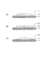
図2に、予備成形体7の具体例を示す。図2(A)は、図1の成形工程により得られる予備成形体7を示している。つまり、この予備成形体7は成形体本体7aに平面を有するものである。図2(B)は、成形体本体7aが凹面を有する予備成形体7Aを示しており、図2(C)は、成形体本体7aが凸面を有する予備成形体7Bを示している。これらの具体例から分かるように、上金型2の凹部2aの形状のバリエーションを増やせば、多種多様な形状(任意の曲面;凸面,凹面;球面,シリンドリカル面等)のカバーガラス板8を作製することができる。また、図2(C)に示すように成形体本体7aが凸面を有する場合、側面での厚さが薄すぎて画像表示面の矩形に対応した4面の外形枠加工は困難であるが、この実施の形態の構成によれば、側面での厚さが薄すぎても、はみ出し部分7bを平面研削又は平面研磨で予備成形体7からすべて取り除くことが容易に可能である。
FIG. 2 shows a specific example of the preform 7. FIG. 2A shows a preform 7 obtained by the molding process of FIG. That is, the preformed body 7 has a flat surface on the molded body
上面8a及び側面8bを鏡面にすることは、上金型2に対する離型性を低下させる方向に作用するが、はみ出し部分7bがあることにより上金型2に対する離型性が良くなる。このため、プレス工程(C)後に予備成形体7が下金型1上に載った状態を安定的に保つことが可能となり、下金型1からの予備成形体7のピックアップが容易になる。また、プレス工程(C)においてはみ出し部分7bと接触する上金型2の外部表面S2(図1(B))を、凹部2aの内部表面S1(図1(B))よりも粗くすると、成形完了後のガラス収縮作用により粗面部の剥離が発生し、予備成形体の接触面の離型が促進されるため、予備成形体7の離型性を効果的に向上させることが可能となる。
Setting the
この実施の形態では、カバーガラス板8のサイズとして、縦×横×厚さ(d1)=80×100×0.7(mm)を想定している。カバーガラス板8の厚さd1(図1(F))は0.2〜1.5mmが好ましく、0.7〜1.0mmが更に好ましい。また、成形体本体7aの厚さd1とのバランスから、はみ出し部分7bの厚さd2(図1(F))は0.5〜1.0mm程度が好ましい。はみ出し部分7bが薄すぎると割れやすくなり、側面8bの形状精度が低下する。逆に、はみ出し部分7bが厚すぎると、平面研削・平面研磨に要する時間が長くなってしまう。また、体積が大きくなるにしたがってひけ量が増大してしまい、成形面の劣化が生じるおそれがある。はみ出し部分7bが生じないようにすると、上型の凹面内に空間が生じて高精度成型ができなくなるおそれがあり、安定した成型を行う上で体積制御が困難になる。
In this embodiment, the size of the cover glass plate 8 is assumed to be length × width × thickness (d1) = 80 × 100 × 0.7 (mm). The thickness d1 (FIG. 1 (F)) of the cover glass plate 8 is preferably 0.2 to 1.5 mm, and more preferably 0.7 to 1.0 mm. Moreover, from the balance with the thickness d1 of the molded
1 下金型
1a 平面部
2 上金型
2a 凹部
3 溶融ガラス
4 ヒータ
5 ブレード
6 白金ノズル
7,7A,7B 予備成形体
7a 成形体本体
7b はみ出し部分
7s 接触面
8 カバーガラス板
8a 上面
8b 側面
8c 下面
S1 内部表面
S2 外部表面
DESCRIPTION OF
Claims (7)
平面部を有する下金型に一定量の溶融ガラスを滴下する滴下工程と、
前記下金型上の溶融ガラスを、成形用の凹部を有する上金型でプレスすることにより、前記溶融ガラスを上金型の前記凹部に充填し、更に前記凹部から上金型と下金型との間にはみ出させて、前記凹部からはみ出したはみ出し部分を有する予備成形体を形成するプレス工程と、
前記はみ出し部分を前記予備成形体からすべて取り除く加工工程と、
を有することを特徴とするデジタル機器用カバーガラス板の製造方法。 A method of manufacturing a cover glass plate for a digital device that protects a digital device having an image display function,
A dropping step of dropping a certain amount of molten glass into a lower mold having a flat surface ;
The molten glass on the lower mold, by pressing with the upper mold having a concave portion for forming, filling the molten glass in the recess of the upper die, further upper mold and the lower mold from the recess And a pressing step of forming a preform having a protruding portion protruding from the recess ,
A processing step of removing all the protruding portions from the preform,
The manufacturing method of the cover glass plate for digital devices characterized by having.
Priority Applications (1)
| Application Number | Priority Date | Filing Date | Title |
|---|---|---|---|
| JP2011077440A JP5434948B2 (en) | 2011-03-31 | 2011-03-31 | Manufacturing method of cover glass plate |
Applications Claiming Priority (1)
| Application Number | Priority Date | Filing Date | Title |
|---|---|---|---|
| JP2011077440A JP5434948B2 (en) | 2011-03-31 | 2011-03-31 | Manufacturing method of cover glass plate |
Publications (3)
| Publication Number | Publication Date |
|---|---|
| JP2012211044A JP2012211044A (en) | 2012-11-01 |
| JP2012211044A5 JP2012211044A5 (en) | 2013-11-28 |
| JP5434948B2 true JP5434948B2 (en) | 2014-03-05 |
Family
ID=47265369
Family Applications (1)
| Application Number | Title | Priority Date | Filing Date |
|---|---|---|---|
| JP2011077440A Expired - Fee Related JP5434948B2 (en) | 2011-03-31 | 2011-03-31 | Manufacturing method of cover glass plate |
Country Status (1)
| Country | Link |
|---|---|
| JP (1) | JP5434948B2 (en) |
Families Citing this family (2)
| Publication number | Priority date | Publication date | Assignee | Title |
|---|---|---|---|---|
| JP5435018B2 (en) * | 2011-12-15 | 2014-03-05 | コニカミノルタ株式会社 | Sheet glass blanks, manufacturing method thereof, and manufacturing method of cover glass plate |
| JP2014115544A (en) * | 2012-12-12 | 2014-06-26 | Nippon Electric Glass Co Ltd | Cover glass for mobile display and mobile display |
Family Cites Families (7)
| Publication number | Priority date | Publication date | Assignee | Title |
|---|---|---|---|---|
| KR19990068730A (en) * | 1999-06-15 | 1999-09-06 | 성필호 | Cover glass used to plat display |
| JP2003248106A (en) * | 2002-02-25 | 2003-09-05 | Mitsubishi Electric Corp | Optical element |
| JP3898176B2 (en) * | 2003-10-01 | 2007-03-28 | 旭テクノグラス株式会社 | Sheet glass optical element |
| JP5294150B2 (en) * | 2009-01-23 | 2013-09-18 | 日本電気硝子株式会社 | Method for producing tempered glass |
| JP5657586B2 (en) * | 2011-03-30 | 2015-01-21 | Hoya株式会社 | Method for producing cover glass blank for electronic device and method for producing cover glass for electronic device |
| JP5776417B2 (en) * | 2011-07-29 | 2015-09-09 | 旭硝子株式会社 | Glass forming method |
| JP5435018B2 (en) * | 2011-12-15 | 2014-03-05 | コニカミノルタ株式会社 | Sheet glass blanks, manufacturing method thereof, and manufacturing method of cover glass plate |
-
2011
- 2011-03-31 JP JP2011077440A patent/JP5434948B2/en not_active Expired - Fee Related
Also Published As
| Publication number | Publication date |
|---|---|
| JP2012211044A (en) | 2012-11-01 |
Similar Documents
| Publication | Publication Date | Title |
|---|---|---|
| WO2014050376A1 (en) | Glass component fabrication method | |
| TW200932470A (en) | Rectangular optical glass lens and manufacturing method thereof | |
| KR20140111403A (en) | Apparatus and method for making shaped glass | |
| TWI404681B (en) | Method for molding sheet glass and molding mold | |
| JP5434948B2 (en) | Manufacturing method of cover glass plate | |
| JPWO2014097830A1 (en) | Method for producing glass molded body and mold | |
| JP4770214B2 (en) | Manufacturing method of glass lens | |
| JP2006188388A (en) | Method for manufacturing glass lens, and glass lens | |
| JP2004339039A (en) | Optical element manufacturing method | |
| US20100242544A1 (en) | Optical lens forming mold | |
| WO2013088808A1 (en) | Method for manufacturing cover glass plate | |
| CN101386465A (en) | Mould of moulded glass | |
| JP5321301B2 (en) | Optical element manufacturing method | |
| JP2017149607A (en) | Press molding die and method for manufacturing optical element | |
| JP5862768B2 (en) | Glass plate manufacturing method and manufacturing apparatus | |
| WO2013153940A1 (en) | Method for producing optical component | |
| JP5436966B2 (en) | Manufacturing method of sintered gear | |
| JP5751209B2 (en) | Glass plate manufacturing method and manufacturing apparatus | |
| JP2014062043A (en) | Plate glass blank and manufacturing method of the same, and manufacturing method of cover glass plate | |
| CN107056030A (en) | The manufacture method of glass elements and glass elements | |
| JP2012211044A5 (en) | ||
| JPWO2016051619A1 (en) | Optical lens | |
| JP2011246314A (en) | Upper mold for droplet-molding, optical element and method for producing optical element | |
| JP6622545B2 (en) | Glass forming apparatus and glass forming method | |
| CN102157167B (en) | Chunk glass and manufacture method thereof, the substrate of magnetic recording media and magnetic recording media |
Legal Events
| Date | Code | Title | Description |
|---|---|---|---|
| A711 | Notification of change in applicant |
Free format text: JAPANESE INTERMEDIATE CODE: A712 Effective date: 20130418 |
|
| A621 | Written request for application examination |
Free format text: JAPANESE INTERMEDIATE CODE: A621 Effective date: 20130924 |
|
| A521 | Written amendment |
Free format text: JAPANESE INTERMEDIATE CODE: A523 Effective date: 20131015 |
|
| A871 | Explanation of circumstances concerning accelerated examination |
Free format text: JAPANESE INTERMEDIATE CODE: A871 Effective date: 20131015 |
|
| A975 | Report on accelerated examination |
Free format text: JAPANESE INTERMEDIATE CODE: A971005 Effective date: 20131105 |
|
| TRDD | Decision of grant or rejection written | ||
| A01 | Written decision to grant a patent or to grant a registration (utility model) |
Free format text: JAPANESE INTERMEDIATE CODE: A01 Effective date: 20131112 |
|
| A61 | First payment of annual fees (during grant procedure) |
Free format text: JAPANESE INTERMEDIATE CODE: A61 Effective date: 20131125 |
|
| R150 | Certificate of patent or registration of utility model |
Ref document number: 5434948 Country of ref document: JP Free format text: JAPANESE INTERMEDIATE CODE: R150 Free format text: JAPANESE INTERMEDIATE CODE: R150 |
|
| LAPS | Cancellation because of no payment of annual fees |